Impact driver
Cooper , et al. Sept
U.S. patent number D859,115 [Application Number D/656,682] was granted by the patent office on 2019-09-10 for impact driver. This patent grant is currently assigned to Black & Decker Inc.. The grantee listed for this patent is BLACK & DECKER INC.. Invention is credited to Jason Busschaert, Joseph B. Cooper, David Miller, Robert Schoch.


| United States Patent | D859,115 |
| Cooper , et al. | September 10, 2019 |
Impact driver
Claims
CLAIM The ornamental design for an impact driver, as shown and described.
| Inventors: | Cooper; Joseph B. (Baltimore, MD), Busschaert; Jason (Bel Air, MD), Schoch; Robert (Baltimore, MD), Miller; David (Aberdeen, MD) | ||||||||||
|---|---|---|---|---|---|---|---|---|---|---|---|
| Applicant: |
|
||||||||||
| Assignee: | Black & Decker Inc. (New
Britain, CT) |
||||||||||
| Appl. No.: | D/656,682 | ||||||||||
| Filed: | July 16, 2018 |
Related U.S. Patent Documents
| Application Number | Filing Date | Patent Number | Issue Date | ||
|---|---|---|---|---|---|
| 29621949 | Oct 12, 2017 | D838156 | |||
| Current U.S. Class: | D8/68 |
| Current International Class: | 0805 |
| Field of Search: | ;D8/61,67,68 ;81/57,57.11,57.14,57.26,429,464,469 ;173/2,170,176 |
References Cited [Referenced By]
U.S. Patent Documents
| D820656 | June 2018 | Waldron |
| D830148 | October 2018 | Waldron |
| D835960 | December 2018 | Koeniger |
| D835961 | December 2018 | Kachar |
| D838156 | January 2019 | Cooper |
| D839069 | January 2019 | Koeniger |
| D840778 | February 2019 | Waldron |
| D843188 | March 2019 | Croghan |
| D843804 | March 2019 | Croghan |
Other References
|
Pictures of prior art of DeWalt 20v Max XR 1/4'' 3-Speed Impact Driver DCF887B www.dewalt.com/en-us/products/power-tools/impact-drivers-and-wren- ches/20v-max-xr-14-3speed-impact-driver-bare/dcf887b; accessed on Aug. 28, 2018. cited by applicant. |
Primary Examiner: Murphy; Austin
Attorney, Agent or Firm: Valancius; Stephen R.
Description
FIG. 1 is a perspective left view of an impact driver showing my new design;
FIG. 2 is a perspective right side view thereof;
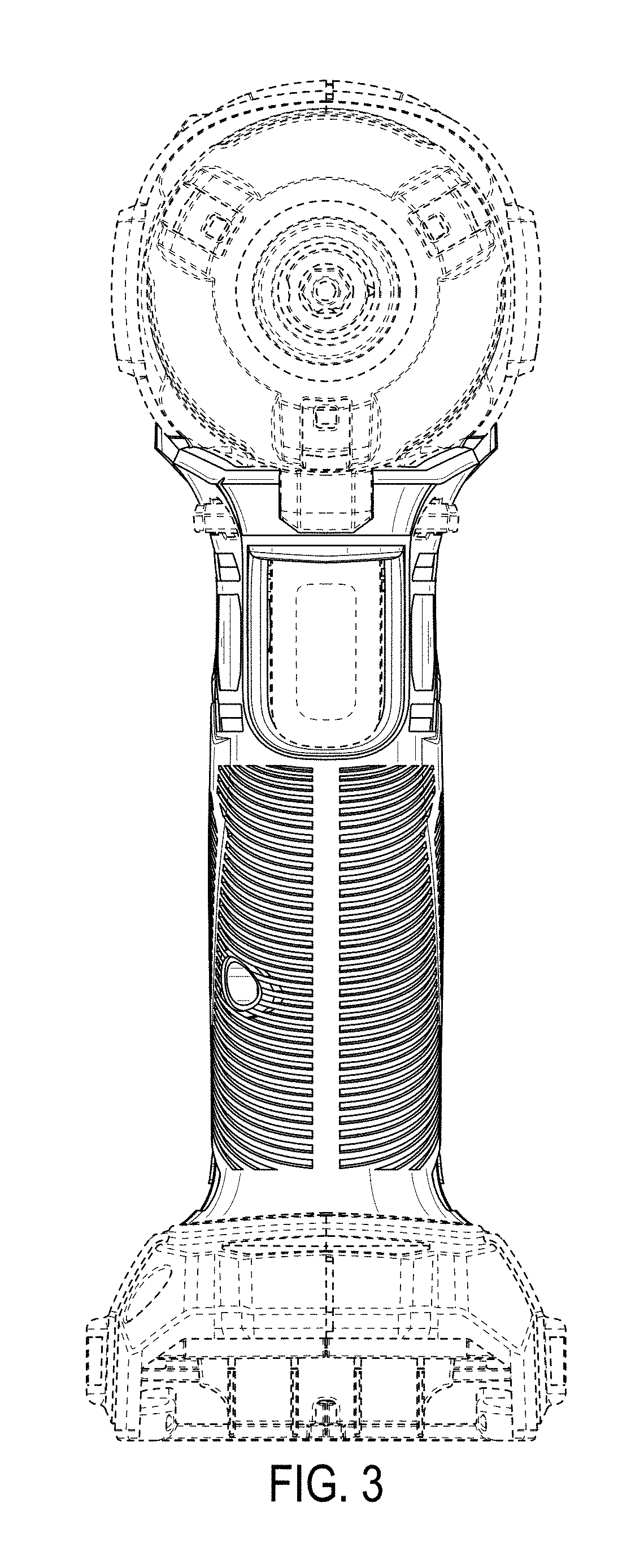
FIG. 3 is a front view thereof;
FIG. 4 is a rear view thereof;
FIG. 5 is a left side view thereof;
FIG. 6 is a right side view thereof
FIG. 7 is a bottom plan view; and,
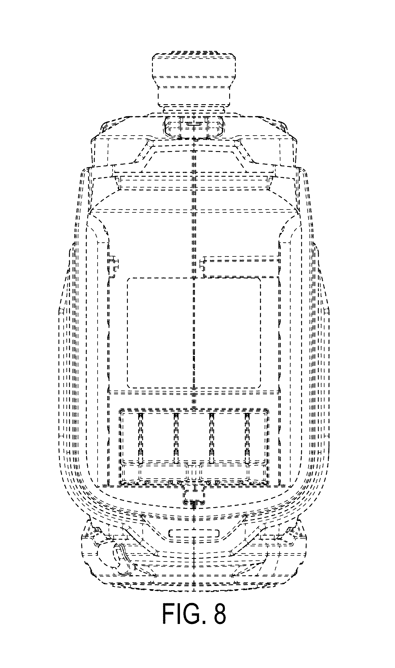
FIG. 8 is a top plan view thereof.
In the above drawings, the broken lines and the areas within the broken lines form no part of the claimed design.
* * * * *
References
D00000
D00001
D00002
D00003
D00004
D00005
D00006
D00007
D00008
XML
uspto.report is an independent third-party trademark research tool that is not affiliated, endorsed, or sponsored by the United States Patent and Trademark Office (USPTO) or any other governmental organization. The information provided by uspto.report is based on publicly available data at the time of writing and is intended for informational purposes only.
While we strive to provide accurate and up-to-date information, we do not guarantee the accuracy, completeness, reliability, or suitability of the information displayed on this site. The use of this site is at your own risk. Any reliance you place on such information is therefore strictly at your own risk.
All official trademark data, including owner information, should be verified by visiting the official USPTO website at www.uspto.gov. This site is not intended to replace professional legal advice and should not be used as a substitute for consulting with a legal professional who is knowledgeable about trademark law.