Audio control device
Chou , et al.
U.S. patent number D851,071 [Application Number D/613,855] was granted by the patent office on 2019-06-11 for audio control device. This patent grant is currently assigned to Kingston Digital, Inc.. The grantee listed for this patent is Kingston Digital, Inc.. Invention is credited to Peter Leekuo Chou, Baron King Lee, Pen Hao Ma, Guan Hua Tzeng.


| United States Patent | D851,071 |
| Chou , et al. | June 11, 2019 |
Audio control device
Claims
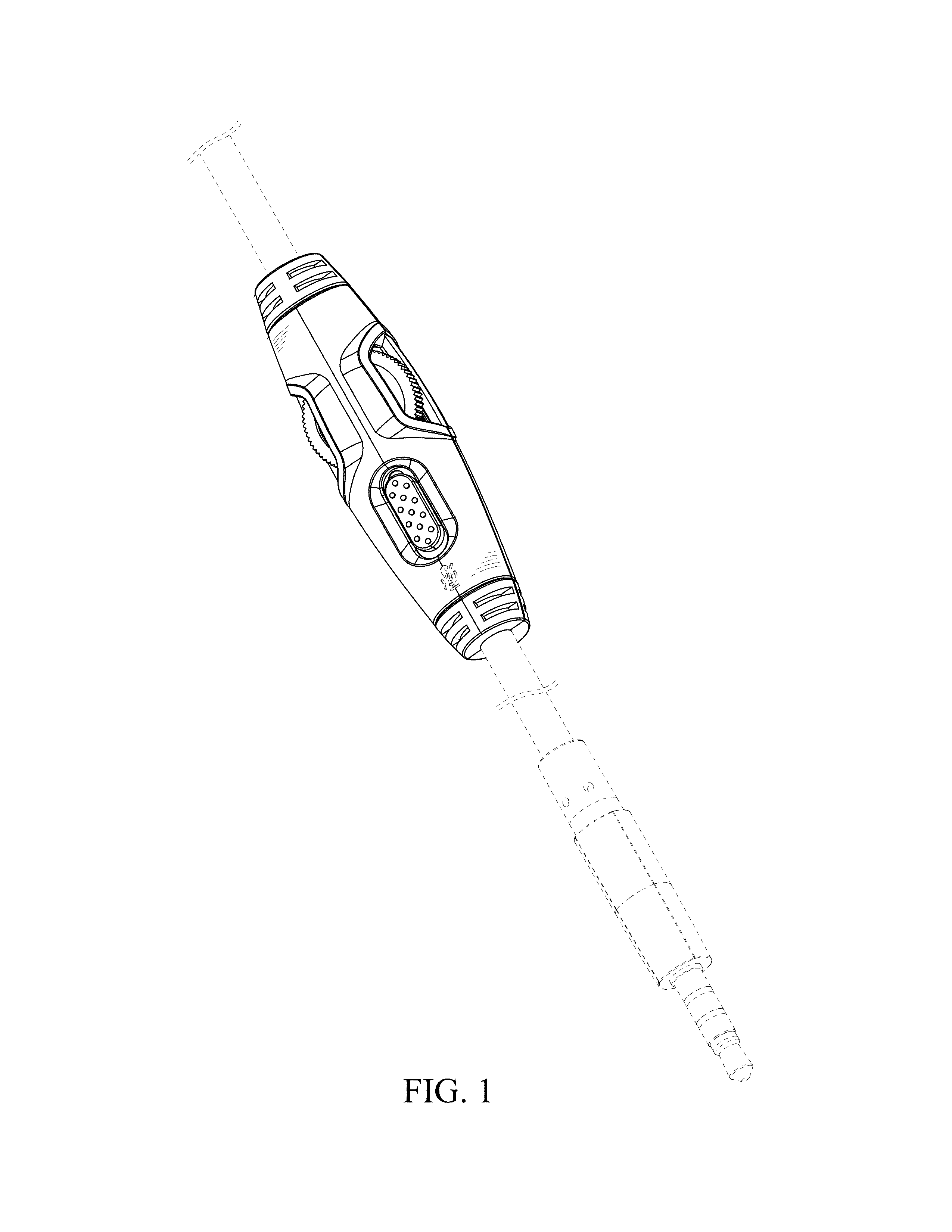
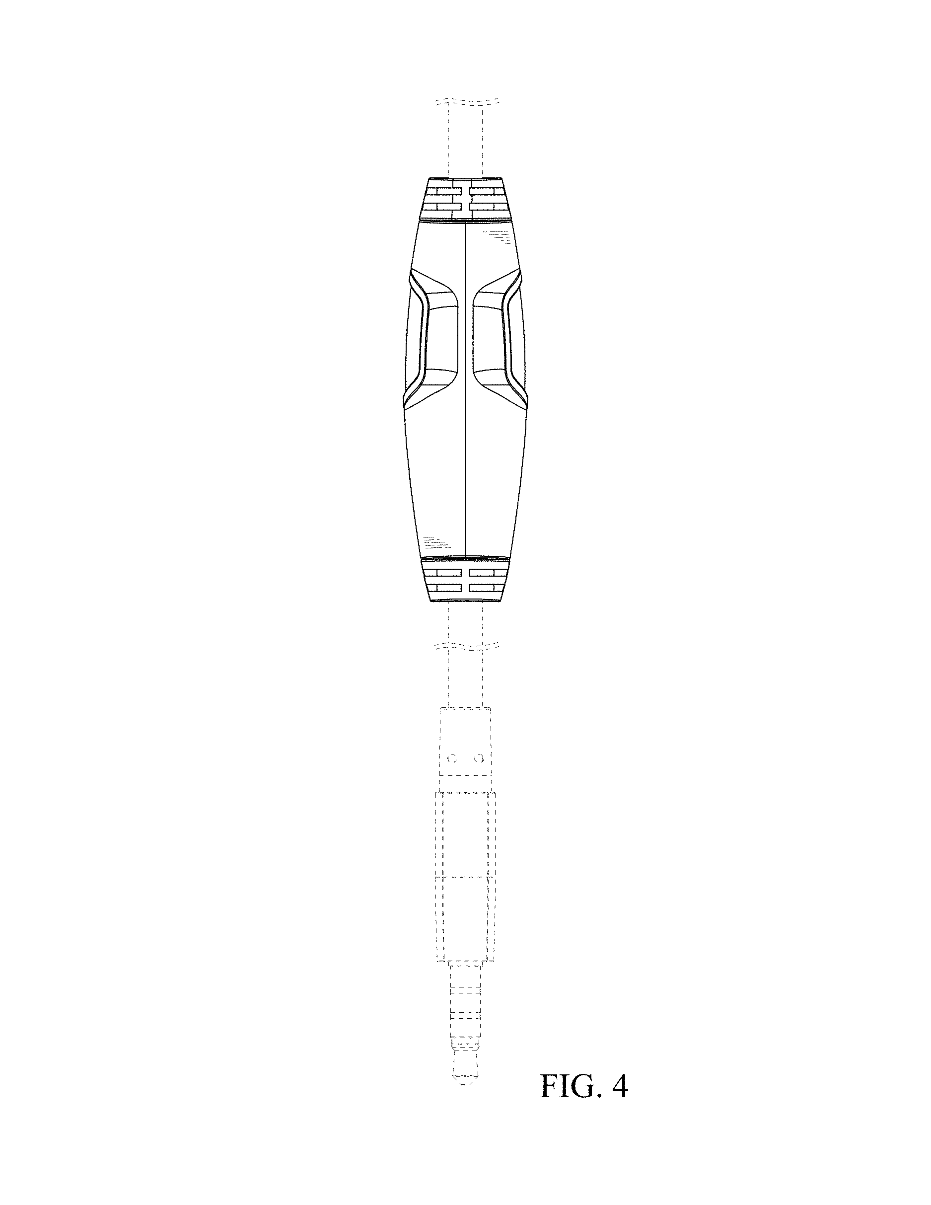
CLAIM We claim an ornamental design for an audio control device, as shown and described.
| Inventors: | Chou; Peter Leekuo (Fountain Valley, CA), Lee; Baron King (Fountain Valley, CA), Tzeng; Guan Hua (Hsinchu, TW), Ma; Pen Hao (Hsinchu, TW) | ||||||||||
|---|---|---|---|---|---|---|---|---|---|---|---|
| Applicant: |
|
||||||||||
| Assignee: | Kingston Digital, Inc.
(Fountain Valley, CA) |
||||||||||
| Appl. No.: | D/613,855 | ||||||||||
| Filed: | August 14, 2017 |
Foreign Application Priority Data
| Mar 27, 2017 [TW] | 106301583 | |||
| Current U.S. Class: | D14/218 |
| Current International Class: | 1401 |
| Field of Search: | ;D14/218,205,188,192,240 ;D13/168,184,153,147 ;D10/104.1,106.1 ;379/430,431 ;381/380,381,370,374 ;455/90.3,575.1,569.1 ;340/384.2 |
References Cited [Referenced By]
U.S. Patent Documents
| 1893474 | January 1933 | Lieber |
| 3047089 | July 1962 | Zwislocki |
| 3049582 | August 1962 | Shinn |
| 3539031 | November 1970 | Scanlon |
| 4069400 | January 1978 | Johanson |
| 4375016 | February 1983 | Harada |
| D310063 | August 1990 | Cheng |
| 4972492 | November 1990 | Tanaka |
| 4990103 | February 1991 | Sazaki |
| 5146051 | September 1992 | Hermann |
| D344522 | February 1994 | Taniguchi |
| D363933 | November 1995 | Starck |
| 5606305 | February 1997 | Jan |
| D384072 | September 1997 | Ng |
| 6030258 | February 2000 | Fumikura |
| D434381 | November 2000 | Shimojyo |
| 6257914 | July 2001 | Comerci |
| D451077 | November 2001 | Montagnino |
| D456366 | April 2002 | Montagnino |
| D462945 | September 2002 | Skulley |
| D465477 | November 2002 | Beraut |
| D530681 | October 2006 | Huang |
| D576105 | September 2008 | Victor |
| D594440 | June 2009 | Hynecek |
| D597690 | August 2009 | Yamamoto |
| D606980 | December 2009 | Bradford |
| D616870 | June 2010 | Choo |
| D633447 | March 2011 | Schaal |
| D710828 | August 2014 | Liu |
| D717275 | November 2014 | Burgett |
| D726163 | April 2015 | Bekhradi |
| D726831 | April 2015 | Lee |
| D730873 | June 2015 | Petterson |
| D736184 | August 2015 | Olivar |
| D770421 | November 2016 | Pettersen |
| D778264 | February 2017 | Stapelbroek |
| D793995 | August 2017 | Nakagawa |
| D794609 | August 2017 | Meyer |
| D808359 | January 2018 | Meyer |
| D811371 | February 2018 | Meyer |
| 2012/0326852 | December 2012 | Harris |
Attorney, Agent or Firm: Skaar Ulbrich Macari, P.A.
Description
FIG. 1 is a perspective view of an audio control device showing the claimed design;
FIG. 2 is another perspective view of FIG. 1;
FIG. 3 is a front elevational view of FIG. 1;
FIG. 4 is a rear elevational view of FIG. 1;
FIG. 5 is a left side elevational view of FIG. 1;
FIG. 6 is a right side elevational view of FIG. 1;
FIG. 7 is a top plan view of FIG. 1; and,
FIG. 8 is a bottom plan view of FIG. 1.
The broken lines in the figures represent portions of the article which form no part of the claimed design.
* * * * *
D00000
D00001
D00002
D00003
D00004
D00005
D00006
D00007
XML
uspto.report is an independent third-party trademark research tool that is not affiliated, endorsed, or sponsored by the United States Patent and Trademark Office (USPTO) or any other governmental organization. The information provided by uspto.report is based on publicly available data at the time of writing and is intended for informational purposes only.
While we strive to provide accurate and up-to-date information, we do not guarantee the accuracy, completeness, reliability, or suitability of the information displayed on this site. The use of this site is at your own risk. Any reliance you place on such information is therefore strictly at your own risk.
All official trademark data, including owner information, should be verified by visiting the official USPTO website at www.uspto.gov. This site is not intended to replace professional legal advice and should not be used as a substitute for consulting with a legal professional who is knowledgeable about trademark law.