State-based Control Systems And Methods
Harris; Glen McLean ; et al.
U.S. patent application number 13/453651 was filed with the patent office on 2012-12-27 for state-based control systems and methods. This patent application is currently assigned to Logitech Europe S.A.. Invention is credited to Glen McLean Harris, Justin M. Henry.
| Application Number | 20120326852 13/453651 |
| Document ID | / |
| Family ID | 36931614 |
| Filed Date | 2012-12-27 |


View All Diagrams
| United States Patent Application | 20120326852 |
| Kind Code | A1 |
| Harris; Glen McLean ; et al. | December 27, 2012 |
STATE-BASED CONTROL SYSTEMS AND METHODS
Abstract
A state-based remote control system for providing efficient and simple operation of a plurality of electronic devices as a coordinated system based upon an overall task. The state-based remote control system includes a housing, a keypad in communication with an electronic system contained within the housing, and a communication device in communication with the electronic system for communicating with external electronic devices. The electronic system monitors the buttons selected by a user to determine the state of all external electronic devices that are to be controlled. When the user selects a task (e.g. watch television), the electronic system automatically determines the actions required to achieve the desired task based upon the current state of the external electronic devices. After the task has been fulfilled, the electronic system updates the data to reflect the modified state of the external electronic devices.
| Inventors: | Harris; Glen McLean; (Auckland, NZ) ; Henry; Justin M.; (Mississauga, CA) |
| Assignee: | Logitech Europe S.A. Morges CH |
| Family ID: | 36931614 |
| Appl. No.: | 13/453651 |
| Filed: | April 23, 2012 |
Related U.S. Patent Documents
| Application Number | Filing Date | Patent Number | ||
|---|---|---|---|---|
| 11411398 | Apr 25, 2006 | |||
| 13453651 | ||||
| 10870339 | Jun 16, 2004 | 8026789 | ||
| 11411398 | ||||
| 09804718 | Mar 12, 2001 | 6784805 | ||
| 10870339 | ||||
| 60189487 | Mar 15, 2000 | |||
| 60253727 | Nov 29, 2000 | |||
| Current U.S. Class: | 340/12.54 ; 340/12.22 |
| Current CPC Class: | H04N 21/4532 20130101; H04N 21/42206 20130101; G08C 2201/50 20130101; H04N 21/41265 20200801; H04N 21/4131 20130101; H04N 21/42204 20130101; G08C 23/04 20130101; G08C 17/02 20130101 |
| Class at Publication: | 340/12.54 ; 340/12.22 |
| International Class: | G08C 19/16 20060101 G08C019/16 |
Claims
1-16. (canceled)
17. A state-machine system, comprising: a processor configured to operate a state machine, wherein the state machine is a model of states and state transitions of at least one external electronic device, and wherein the processor is configured to navigate the state machine to calculate, update, and store simulated states from simulated state transitions of the state machine for the at least one external electronic device; a user input device coupled to the processor and configured to receive input from a user for changing a current state of the at least one external electronic device to another state associated with the input; and a transmitter coupled to the processor and configured to transmit a set of control signals to the at least one external electronic device for changing the current state of the at least one external electronic device to the another state, wherein the processor is configured to receive the input from the user input device to navigate the state machine to calculate, update, and store a simulated state corresponding to the another state based on the simulated state transitions, the current state, and the input, and wherein the processor is configured to control transmission by the transmitter.
18. The state-machine system of claim 17, wherein the processor is configured to navigate the state machine to store, calculate, and updated the simulated state prior to controlling the transmitter to transmit a subsequent set of control signals for a subsequent input received from a user.
19. The state-machine system of claim 17, wherein the set of control signals are a dynamic set of control signals.
20. The state-machine system of claim 19, wherein the set of control signals are for a macro.
21. The state-machine system of claim 17, wherein the input device includes a keypad.
22. The state-machine system of claim 17, further comprising a display coupled to the processor, wherein the processor is configured to control the display to display the simulated state.
23. The state-machine system of claim 17, wherein: the processor is configured to operate a plurality of state machines, which includes the first mentioned state machine, the plurality of state machines respectively correspond to a plurality of external electronic devices, which includes the first mentioned external electronic device, each state machine is configured to model states and state transitions of a corresponding one of the external electronic device, and the processor is configured to navigate each of the state machines to store, calculate, and updated simulated states and simulated state transitions of the plurality of external electronic devices.
24. The state-machine system of claim 23, wherein the transmitter is configured to transmit sets of control signals to the plurality of external electronic device for changing the states of the external electronic devices,
25. The state-machine system of claim 19, wherein the processor is configured to modify and execute the dynamic set of control signals based on a desired state of the at least one external electronic device and a comparison of the simulated state.
26. The state-machine system of claim 17, wherein the processor is configured to determine whether to modify a current state of the at least one external electronic device based on whether the simulated state matches a state associated with the input.
27. The state-machine system of claim 17, wherein at least one of the states includes a state of more than one external electronic device.
28. A device including a state-machine, the device comprising: a processor configured to operate a state machine, wherein the state machine is a model of states and state transitions of at least one external electronic device, and wherein the processor is configured to identify a current state and to navigate the state machine to store, calculate, and update a simulated state and a simulated state transition; and a transmitter coupled to the processor and configured to transmit a set of control signals for changing the current state of the at least one external electronic device to a simulated state, wherein the processor is configured to update the current state in the state machine to the simulated state based on the transmitted set of control signals.
29. The device of claim 28, further comprising a user input device coupled to the processor and configured to receive input from a user for changing a state of the at least one external electronic device.
30. The device of claim 29, wherein the processor is configured to navigate the state machine to store, calculate, and update the simulated state prior to controlling the transmitter to transmit a subsequent set of control signals for a subsequent input received via the user input.
31. The device of claim 29, wherein the input device includes a keypad.
32. The device of claim 29, wherein the processor is configured to modify a state of the at least one external electronic device if the simulated state does not match a state associated with the input, and to not modify a state of the at least one external electronic device if the simulated state does match the state associated with the input.
33. The device of claim 28, wherein the set of control signals are a dynamic set of control signals.
34. The device of claim 33, wherein the set of control signals are for a macro.
35. The device of claim 28, further comprising a display coupled to the processor, wherein the processor is configured to control the display to display an aspect of the simulated state.
36. The device of claim 28, wherein: the processor is configured to operate a plurality of state machines, which includes the first mentioned state machine, the plurality of state machines respectively correspond to a plurality of external electronic devices, which includes the first mentioned external electronic device, each state machine is configured to model states and state transitions of a corresponding one of the external electronic device, and the processor is configured to navigate each of the state machines to store, calculate, and updated simulated states and simulated state transitions of the plurality of external electronic devices.
37. The device of claim 36, wherein the transmitter is configured to transmit sets of control signals to the plurality of external electronic device for changing the states of the external electronic devices,
38. The device of claim 28, wherein the processor is configured to modify and execute the set of control signals based on a desired state of the at least one external electronic device and a comparison of the simulated state.
39. The device of claim 28, wherein the device is a remote control.
40. A method of operating a state-machine based device configured to control a set of external electronic devices, comprising: receiving input at a state-machine based device for controlling a set of external electronic devices; and determining on the state-machine based device via navigation of a state machine, which is a model of states and state transitions of the set of external electronic devices, a set of simulated states and a set of simulated state transitions for the set of external electronic devices based on the input and a set of current states of the set of external electronic devices.
41. The method of claim 40, further comprising transmitting from the state-machine based device a set of command codes to the set of external electronic devices for controlling the set of external electronic devices to change state from the set of current states to the set of simulated states
42. The method of claim 40, further comprising storing by the state-machine based device the set of simulated states in a local memory of the state-machine based device, wherein the set of simulated states are the set of current states for a second input, which is subsequent input to the first mentioned input.
43. The method of claim 40, wherein the state machine includes a plurality of state variable, which represent the possible states of the set of external electronic devices.
44. The method of claim 40, wherein the state-machine based device is a remote control device.
45. The method of claim 40, wherein the receiving step includes receiving via a user input the input.
46. The method of claim 40, wherein the set of external electronic devices includes a set of media players.
47. The method of claim 40, wherein the set of media players includes a television set and a video player.
48. The method of claim 40, wherein the set of current states is a set of simulated current states simulated by the state-machine based device via navigation of the state machine.
Description
CROSS-REFERENCE TO RELATED U.S. PROVISIONAL PATENT APPLICATIONS
[0001] This application is a continuation of pending U.S. application Ser. No. 11/411,398 filed Apr. 25, 2006, which is a continuation of U.S. patent application Ser. No. 10/870,339, filed Jun. 16, 2004, which is a combination of U.S. patent application Ser. No. 09/804,718 (now U.S. Pat. No. 6,784,805) filed Mar. 21, 2000, which claims benefit under Title 35, United States Code, Section 119(e) of U.S. provisional patent application Ser. No. 60/189,487 filed Mar. 15, 2000, and U.S. provisional patent application Ser. No. 60/253,727 filed Nov. 29, 2000. The contents of all of which applications are hereby incorporated by reference in their entireties into this patent application.
BACKGROUND OF THE INVENTION
[0002] 1. Field of the Invention
[0003] The present invention relates generally to remote control devices and more specifically it relates to a state-based remote control system for providing efficient and simple operation of a plurality of electronic devices as a coordinated system based upon an overall task.
[0004] 2. Description of the Prior Art
[0005] Remote control devices have been in use for years. Remote control devices are utilized to operate various external electronic devices including but not limited to televisions, stereos, receivers, VCRs, DVD players, CD players, amplifiers, equalizers, tape players, cable units, lighting, window shades and other electronic devices. A conventional remote control is typically comprised of a housing structure, a keypad within the housing structure for entering commands by the user, electronic circuitry within the housing structure connected to the keypad, and a transmitter electrically connected to the electronic circuitry for transmitting a control signal to an electronic device to be operated.
[0006] The user depresses one or more buttons upon the keypad when a desired operation of a specific electronic device is desired. For example, if the user desires to turn the power off to a VCR, the user will depress the power button upon the remote control which transmits a "power off" control signal that is detected by the VCR resulting in the VCR turning off.
[0007] Because of the multiple electronic devices currently available within many homes and businesses today, a relatively new type of remote control is utilized to allow for the control of a plurality of electronic devices commonly referred to as a "universal remote control." Most universal remote controls have "selector buttons" that are associated with the specific electronic device to be controlled by the remote control (i.e. television; VCR, DVD player, etc.).
[0008] A few universal remote controls allow for "macros" to be programmed into the remote control so that when a preprogrammed button is depressed a string of commands is executed as programmed. For example, if the user desires to operate their television along with the stereo receiving input from the television, the user would program a macro for turning on the television, turning on the stereo and then switching the input to the stereo for receiving audio input from the television. The main problem with conventional universal remote controls is that they are unable to detect or monitor the state of a particular electronic device. Another problem with conventional universal remote controls is that when a preprogrammed macro is executed, an undesirable effect can occur wherein electronic devices that are desired to be turned on are actually turned off. For example, if the television is already on but the stereo is tuned to a local radio station and the user selects the above macro the power to the television would actually be turned off instead of maintained on.
[0009] Recently, universal remote controls have been developed that communicate via radio frequency (RF) with external sensing devices that are connected to the electronic devices for detecting the current state of the electronic device. Other remote controls are able to receive and display information from the electronic device they control such as displaying the same of a radio station on a display of the remote. These devices are relatively expensive and again difficult to utilize for the average consumer.
[0010] The main problem with conventional remote control devices is that they are typically unable to know the particular "state" of an electronic device they are to control, particularly universal remote controls. A further problem with conventional remote controls that do allow for advanced configuration thereof to compensate for the various states of the electronic device is that they are often times difficult for the average consumer to utilize. Another problem with conventional remote control devices is that they force consumers to view their electronic devices "individually" (i.e. turn television on, turn stereo on, switch audio input on stereo to television) rather than in broad "tasks" (e.g. watch television).
[0011] While these devices may be suitable for the particular purpose to which they address, they are not as suitable for providing efficient and simple operation of a plurality of electronic devices as a coordinated system based upon an overall task. Conventional remote controls are typically programmed to operate only one electronic device. Conventional universal remote controls are typically programmed to operate electronic devices "individually" or are difficult to configure to automated control of a plurality of electronic devices.
[0012] In these respects, the state-based remote control system according to the present invention substantially departs from the conventional concepts and designs of the prior art, and in so doing provides an apparatus primarily developed for the purpose of providing efficient and simple operation of a plurality of electronic devices as a coordinated system based upon an overall task.
SUMMARY OF THE INVENTION
[0013] In view of the foregoing disadvantages inherent in the known types of remote controls now present in the present art, the present invention provides a new state-based remote control system construction wherein the same cane be utilized for providing efficient and simple operation of a plurality of electronic devices as a coordinated system based upon an overall task.
[0014] The general purpose of the present invention, which will be described subsequently in greater detail, is to provide a new state-based remote control system that has many of the advantages of the remote controls mentioned heretofore and many more features that result in a new state-based remote control system which is not anticipated, rendered obvious, or even suggested, or even implied by any of the prior art remote controls, either alone or in any combination thereof.
[0015] To attain this, the present invention generally comprises a housing, a keypad in communication with an electronic system contained within the housing, and a communication device in communication with the electronic system for communicating with external electronic devices. The electronic system constantly monitors the buttons selected by a user to determine the state of all external electronic devices that are to be controlled. When the user selects a (e.g. watch television), the electronic system automatically determines the actions required to achieve the desired task based upon the current state of the external electronic devices. After the task has been fulfilled, the electronic system updated the data to reflect the modified state of the external electronic devices.
[0016] There has thus been outlined, rather broadly, the more important features of the invention in order that she detailed description thereof may be better understood, and in order that the present contribution to the art may be better appreciated. There are additional features of the invention that will be described hereinafter and that will form the subject matter of the claims appended hereto.
[0017] In this respect, before explaining at least one embodiment of the invention in detail, it is to be understood that the invention is not limited in its application to the details of construction and to the arrangements of the components set forth in the following description or illustrated in the drawings. The invention is capable of other embodiments and of being practiced and carried out in various ways. Also, it is to be understood that the phraseology and terminology employed herein are for the purpose of the description and should not be regarded as limiting.
[0018] A primary object of the present invention is to provide a state-based remote control system that will overcome the shortcomings of the prior art devices.
[0019] A second object is to provide a state-based remote control system for providing efficient and simple operation of a plurality of electronic devices as a coordinated system based upon an overall task.
[0020] Another object is to provide a state-based remote control system that provides for intuitive operation of a plurality of electronic devices.
[0021] An additional object is to provide a state-based remote control system that allows for the simple operation of a plurality of electronic devices based upon an overall "task" instead of specific controls for specific electronic devices.
[0022] A further object is to provide at state-based remote control system that is simple and easy to utilize for the average consumer.
[0023] Another object is to provide a state-based remote control system that does not require significant programming prior to usage.
[0024] An additional object is to provide a state-based remote control system that is affordable.
[0025] Other objects and advantages of the present invention will become obvious to the reader and it is intended that these objects and advantages are within the scope of the present invention.
[0026] To the accomplishment of the above and related objects, this invention may be embodied in the form illustrated in the accompanying drawings, attention being called to the fact, however, that the drawings are illustrative only, and that changes may be made in the specific contraction illustrated and described within the scope of the appended claims.
BRIEF DESCRIPTION OF THE DRAWINGS
[0027] Various other objects, features and attendant advantages of the present invention will become fully appreciated as the same becomes better understood when considered in conjunction with the accompanying drawings, in which like reference characters designate the same or similar parts throughout the several views, and wherein:
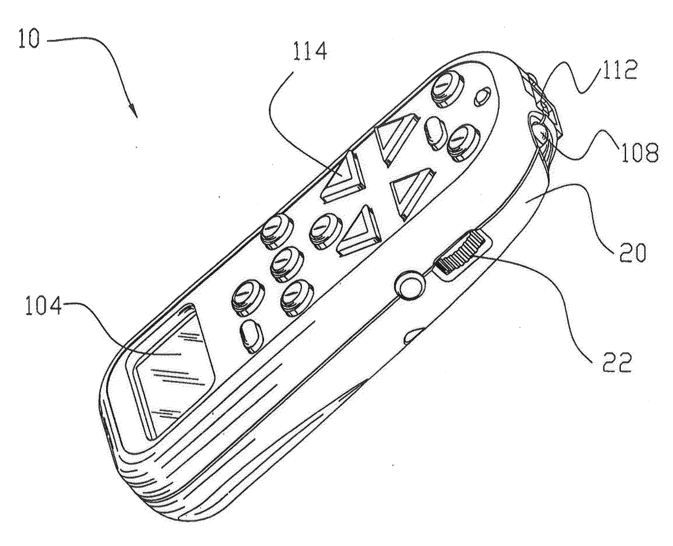
[0028] FIG. 1 is an upper perspective view of the present invention.
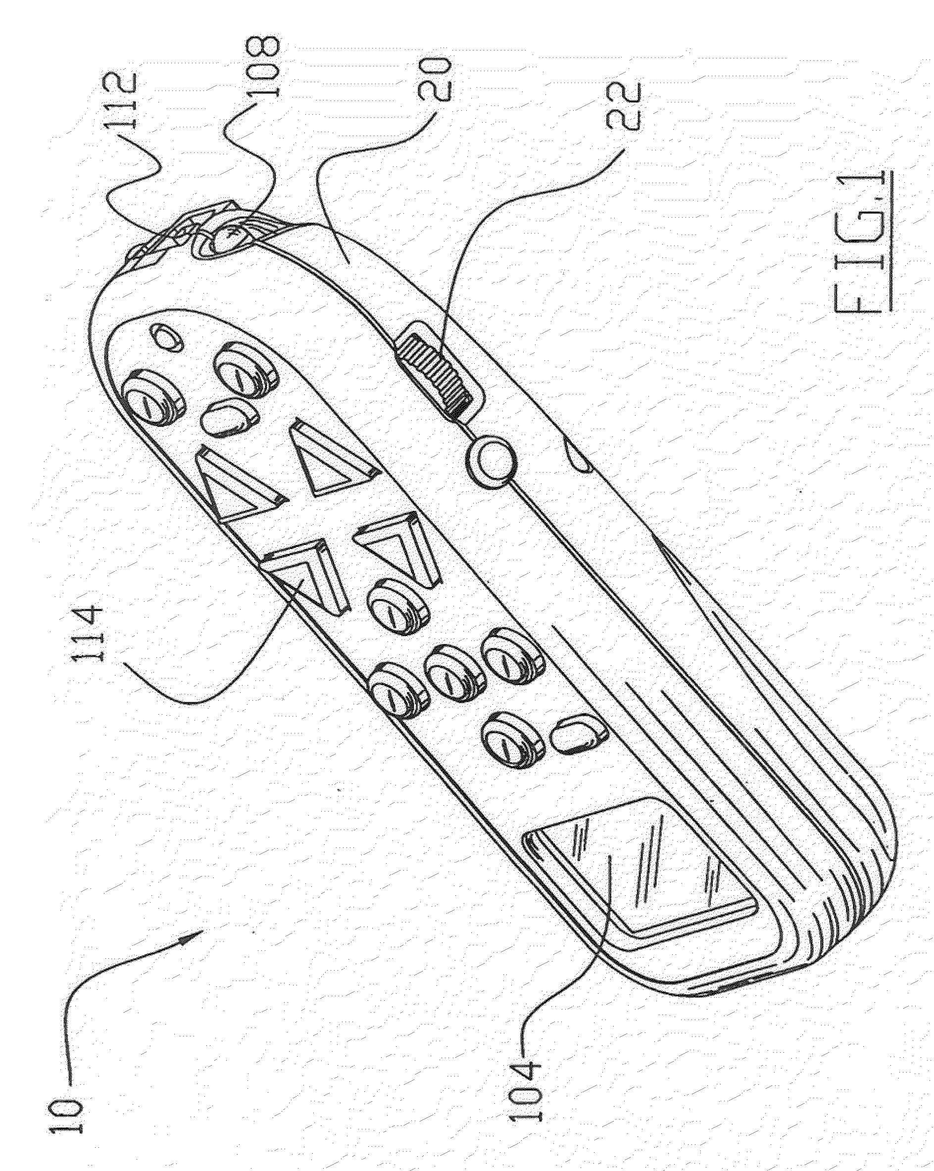
[0029] FIG. 2 is a side view of the present invention.
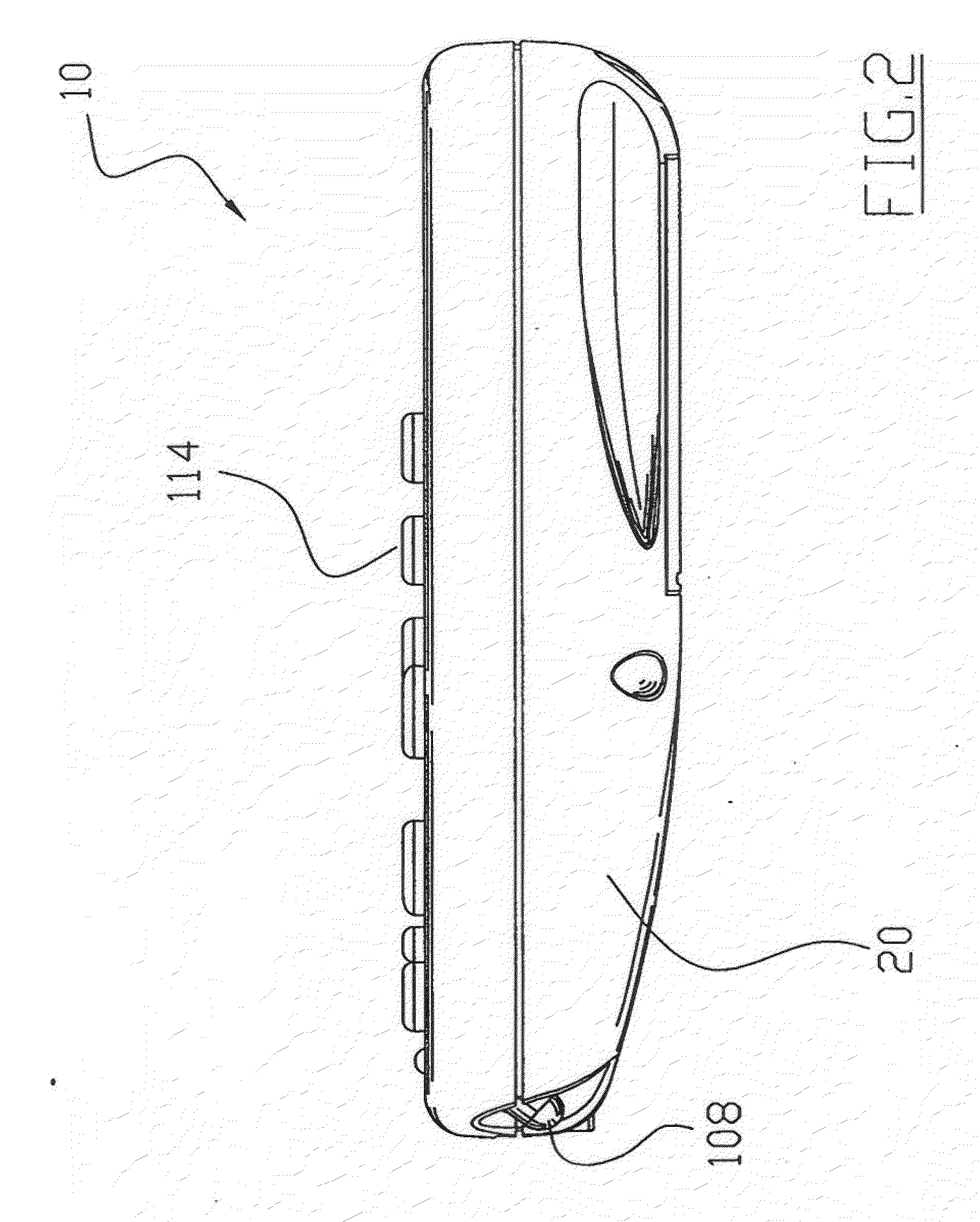
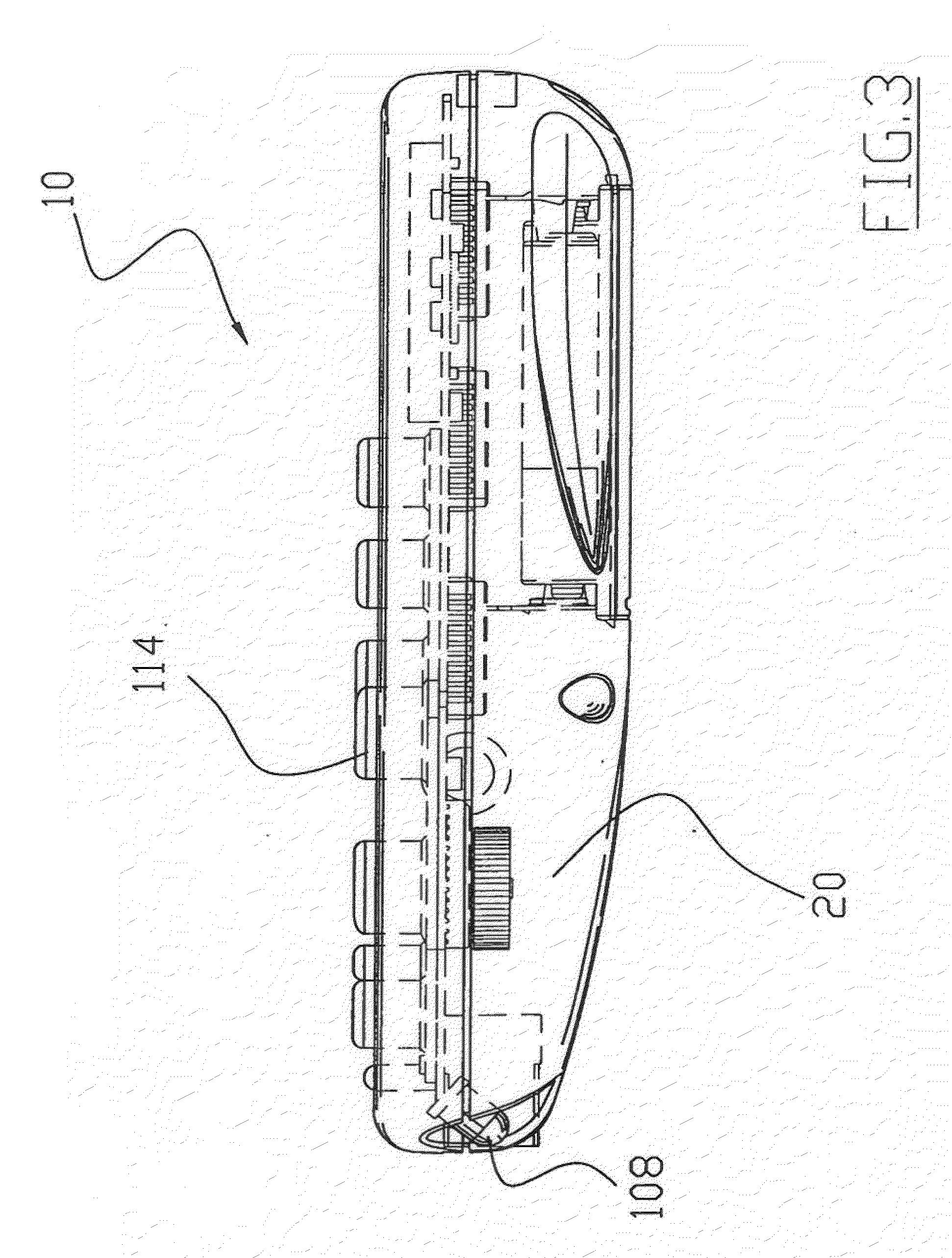
[0030] FIG. 3 is a side view of the present invention illustrating electronic circuitry within.
[0031] FIG. 4 is a block diagram illustrating the communications between the present invention and a plurality of external devices.
[0032] FIG. 5 is a block diagram illustrating the electronic system of the present invention electrically connected to the power source and in communication with the external electronic devices.
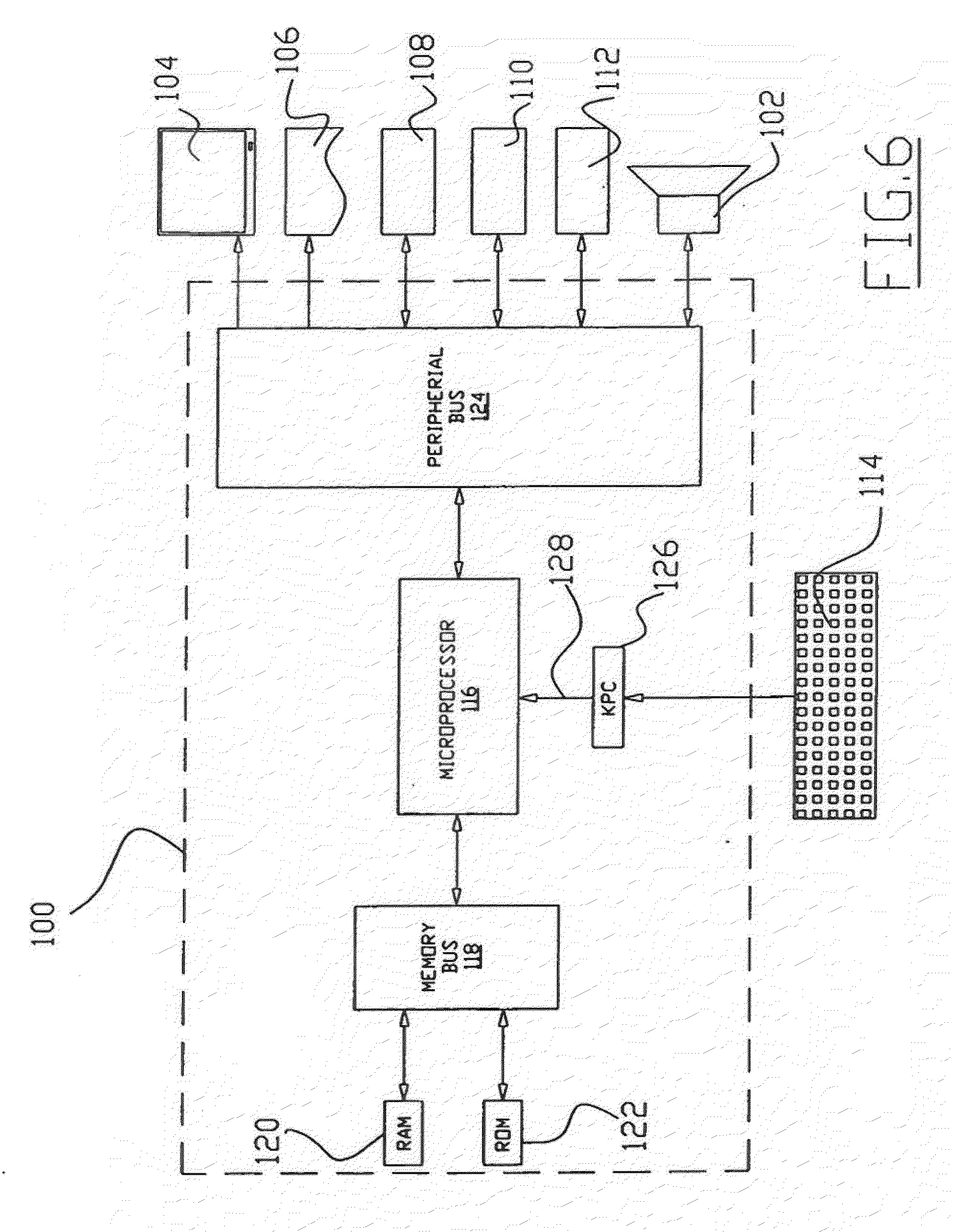
[0033] FIG. 6 is a block diagram illustrating the electronic system along with a plurality of accessory devices connected to thereof.
[0034] FIG. 7 is a flowchart illustrating the initial programming of the present invention prior to usage.
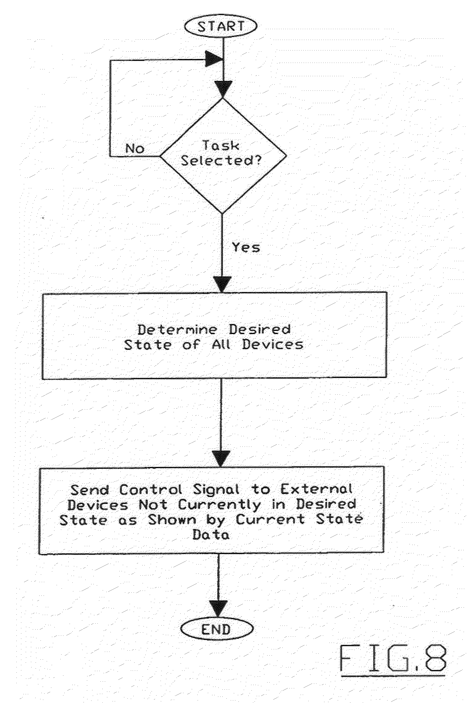
[0035] FIG. 8 is a flowchart illustrating the modification of the state of external electronic devices not in the desired state as desired within a task to be performed.
[0036] FIG. 9 is a flowchart illustrating an action performed upon one or more external devices and modifying the memory within the electronic system accordingly.
[0037] FIG. 10 is a flowchart illustrating the modification of the memory within the electronic system to reflect the changed state of the external electronic devices after a task or an action has been completed.
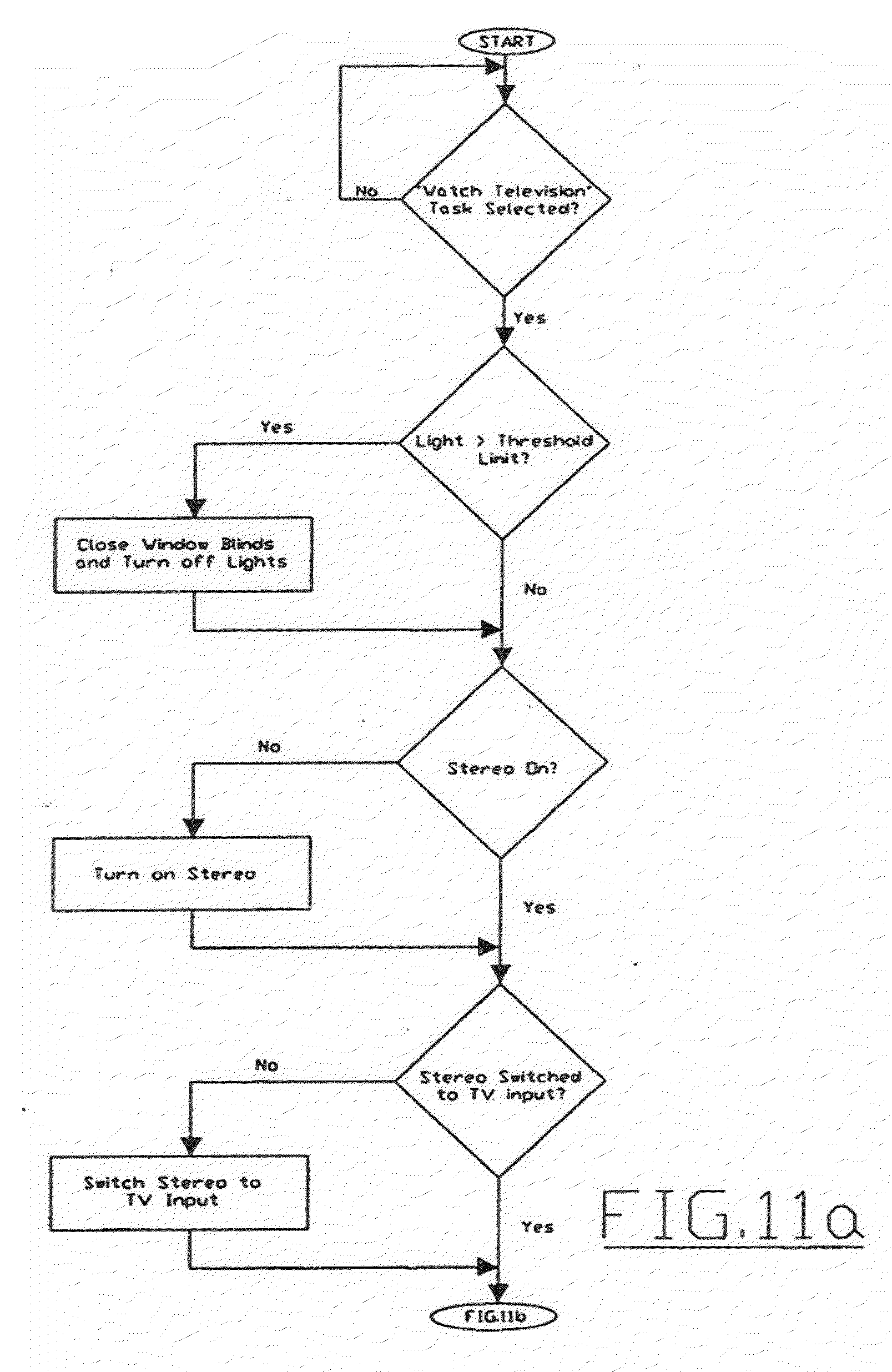
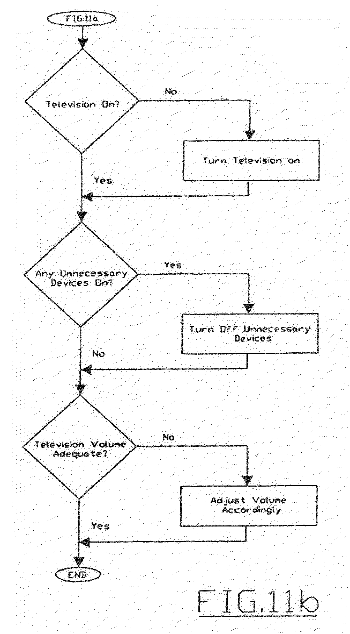
[0038] FIGS. 11 is a flowchart providing an example task for watching television being executed.
DESCRIPTION OF THE PREFERRED EMBODIMENT
[0039] Turing now descriptively to the drawings, in which similar reference characters denote similar elements throughout the several views, FIGS. 1 through 11 illustrate a state-based remote control system 10, which comprises a housing 20, a keypad 114 in communication with an electronic system 100 contained within the housing 26, and a communication device 108 in communication with the electronic system 100 for communicating with external electronic devices 12. The electronic system 100 constantly monitors the buttons of the keypad 114 and other switches selected by a user to determine the state of all external electronic devices 12 that are to be controlled. When the user selects a task (e.g. watch television), the electronic system 100 automatically determines the actions required to achieve the desired task based open the current state of the external electronic devices 12. After the task has been fulfilled, the electronic system 100 updates the data to reflect the modified state of the external electronic devices 12.
A. Housing Structure
[0040] The present invention generally is comprised of a housing 20 having a structure and shape similar to conventional remote control devices. The housing 20 may be constructed of various types of materials and shapes as can be appreciated by one skilled in the art. The housing is preferably structured to be ergonomic for a majority of users.
B. Electronic System
[0041] The present invention is utilized to control and operate various external electronic devices including but not limited to televisions, stereos, receivers, VCRs, DVD players, CD players, simplifiers, equalizers, tape players, cable units, satellite dish receivers, lighting, window shades and other electronic devices. Almost any number of external electronic devices may be controlled by the present invention as will be discussed in further detail.
[0042] FIG. 6 is a block diagram of an exemplary electronic system 100 for practicing the various aspects of the present invention. The electronic system 100 is preferable enclosed within the housing. A portable power source 140 is electrically connected to the electronic system 100 for providing electrical power to the electronic system 100. The power source 140 may be comprised of any power source such as a battery structure (disposable or rechargeable), solar cells, or direct power.
[0043] The electronic system 100 preferably includes a display screen 104, a network interface 112, a keypad 114, a microprocessor 116, a memory bus 118, random access memory (RAM)120, a speaker 102, read only memory (ROM) 122, a peripheral bus 124, a keypad controller 126, and a communications device 108. As can be appreciated, the electronic system 100 of the present invention may be comprised of any combination of well-known computer devices, personal digital assistants (PDAs), laptop computers, remote control devices and other similar electronic structures.
[0044] The microprocessor 116 is a general-purpose distal processer that controls the operation of the electrode system 100. The microprocessor 116 can be a single-chip processor or implemented with multiple components. Using instructions retrieved from memory, the microprocessor 116 controls the reception and manipulations of input data and the output and display of data on output devises.
[0045] The memory bus 118 is utilized by the microprocessor 116 to access RAM 120 and ROM 122. RAM 120 is used by microprocessor 116 as a general storage area and as scratch-pad memory, and can also be used to store input data and processed data. ROM 122 can be used to store instructions or program code followed by microprocessor 116 as well as other data.
[0046] Peripheral bus 124 is used to access the input, output and storage devices used by the electronic system 100. In the described embodiment(s), these devices include a display screen 104, an accessory device 106, a speaker 102, a communications device 108, and a network interface 112. A keypad controller 126 is used to receive input from the keypad 114 and send decoded symbols for each pressed key to microprocessor 116 over bus 128.
[0047] The display screen 104 is an output device that displays images of data provided by the microprocessor 116 via the peripheral bus 124 or provided by other components in the electronic system 100. Other output devices such as a printer, plotter, typesetter, etc. can be utilized as an accessory device 106.
[0048] The microprocessor 116 together with an operating system operate to execute computer code and produce and use data. The computer code and data may reside on RAM 120, ROM 122, or other storage mediums. The computer code and data could also reside on a removable program medium and loaded or installed onto the electronic system 100 when needed. Removable program mediums include, for example, PC-CARD, flash memory, and floppy disk.
[0049] The network interface 112 is utilized to send and receive data over a network connected to other electronic systems. The network interface may be comprised of a Universal Serial Bus (USB), an external bus standard that supports data transfer rates of 12 Mbps (12 million bits per second). A single USB port can be used to connect to 127 peripheral devices, such as mice, modems, and keyboards. An interface card or similar device and appropriate software implemented by microprocessor 116 can be utilized to connect the electronic system 100 to an existing network and transfer data according to standard protocols including data over a global computer network such as the Internet.
[0050] The keypad 114 is used by a user to input commands and other instructions to the electronic system 100. Other types of user input devices can also be used in conjunction with the present invention. For example, pointing devices such as a computer mouse, a jog switch 22, a track ball, a stylus, or a tablet to manipulate a pointer on a screen of the electronic system 100.
[0051] The present invention can also be embodied as computer readable code on a composer readable medium. The computer readable medium is any data storage device that can store data which can be thereafter be read by a electronic system. Examples of the computer readable medium include read-only memory, random-access memory, magnetic data storage devices such as diskettes, and optical data storage devices such as CD-ROMs. The computer readable medium can also be distributed over a network coupled electronic systems so that the computer readable code is stored and executed in a distributed fashion.
[0052] The communications device 108 may be comprised of any well-known communication system that allows communications with external electronic devices. The communications device 108 may provide for various types of communication such as but not limited to via infrared (IR), wireless (e.g. BLUETOOTH), unidirectional, bi-directional, radio frequency (RF), visible light, ultrasonic and various other means for communicating with external electronic devices.
[0053] The environmental unit 110 senses environmental information such as lighting, motion, orientation, temperature, audio and other environmental information. The environmental unit 110 communicates the detected environmental information to the microprocessor 116 for consideration in controlling the external electronic devices. The environmental 110 includes the appropriate sensors such as light sensors, temperature sensors, sound sensors and other desirable sensors to determine the environment conditions external of the housing.
[0054] Input into the electronic system is accomplished mainly through the usage of the keypad 114. The keypad 114 includes a plurality of buttons that allow the user to execute one or more commands. The keypad 114 allows for the control of basic functions such as volume, channel manipulations, mute, and last channel. However, the keypad 114 may also include several buttons that represent a specific task such as watch television, listen to radio and various other tasks. Various other input devices may be utilized to input data into the electronic system such as a jog switch 22 (i.e. dial), motion and orientation detectors, touch sensitive screens and voice recognition. The display 104 provides information to the user such as possible tasks to complete or the current state of the external electronic devices.
C. Initializing/Synchronizing of Electronic System with External Devices
[0055] Prior to utilizing the present invention, the user must program the electronic system 100 to not only recognize all of the external electronic devices 12 to be controlled but also as to each external electronic device 12 respective current "states" (i.e. on, off, current input, current output, etc.) as is shown in FIG. 7 of the drawings.
[0056] The initial programming of the electronic system 100 may be accomplished through various well-known means such as entering a code for each specific external electronic device. "Sampling" of a signal from a remote control utilized to control a specific electronic device may also be utilized to assist in the programming of the electronic system 100. Various other methods may be utilized to program the electronic system 100 to recognize and control the external electronic devices 12 which are well known in the art.
[0057] After all of the external electrode devices 12 have been properly programmed into the electronic system 100, the user then must program the "current state" of each external electronic device into the electronic system 100. This is accomplished typically by the user answering a series of questions shown on the display regarding each display. For example, the display may ask "Is the television turned on?" which the user would respond to. It can be appreciated that there can also be a default state for all of the external devices as being "off." All of the programmed "Current State Data" is stored within memory of the electronic system 100.
D. Current State Data
[0058] "Current State Data" is data information relating to the current state of each of the external electronic devices 12 stored within the electronic system 100. The "state" of an external electronic device 12 is comprised of various variables such as but not limited to power on, power off, volume level, mute on, mute off, audio input, audio output, video input, video output, lights on, lights off, shades open, shades closed, and various other states common to external electronic devices 12. The Current State Data is updated as actions and/or tasks are performed to provide an accurate reflection of the actual current state of the external electronic devices 12. The Current State Data is utilized by the electronic system 100 to determine what external electronic devices 12 require modification when a "task" is selected by the user to prevent undesirable events from occurring.
E. Actions
[0059] An "action" is a specific event that occurs that typically only affects one of the external devices. An example of an action is when the user selects the power button on the keypad 114 to turn off the television which causes the television to switch from on to off or vice-versa.
[0060] The Current State Data is immediately modified to reflect the changed state of the television or other external electronic device after an action occurs as shown in FIGS. 9 and 10 of the drawings. The Current State Data is constantly updated to maintain an accurate reflection of the actual current state of the external electronic devices 12.
F. Tasks
[0061] A "task" may be comprised of one or more "actions" depending upon (1) the desired state of all external devices as prescribed by the task, and (2) the current state of all external devices. Examples of tasks are "watch television, " "listen to radio," "watch video," "listen to CD's," "watch DVD", and so forth. There are many more tasks that may accomplished with the present invention that are not discussed but are deemed readily apparent to one skilled in the art.
[0062] Each task has a "desired state" for each of the external electronic devices 12. When a task is selected, either through the keypad or the display, the electronic system 100 immediately determines the Current State Data and compares this data to the "Desired State Data" for all of the external electronic devices 12. After determining which external electronic devices 12 are in the desired state and which are not in the desired state, the electronic system 100 transmits a communication signal to the external electronic devices 12 that are not in the desired state to switch to the desired state based upon the task to be preformed.
[0063] Another function of the present invention is to allow for the electronic system 100 to determine what menu options (i.e. "tasks") that are available upon the display 104 based upon the current state of the external electronic devices 12. For example, if the television is currently on, the menu within the display may display the "Turn Television Off" task instead of the "Turn Television On" task which is not required.
G. Watch Television Task Example
[0064] Assuming for the sake of example that a user using the present invention has (1) interior lighting, (2) electronically controlled shades, (3) a stereo, (4) a television, (5) a CD player, and (6) a VCR which are programmed and synchronized within the electronic system as stated above. FIG. 11 illustrates the "WATCH TELEVISION" task. Below is a sample listing of the "Current State Data" prior to the selection of the WATCH TELEVISION task as shown in FIG. 11 of the drawings.
TABLE-US-00001 External Device Initial State Prior to Execution of Task 1. Room Lighting Lights turned on and shades open during evening hours. 2. Stereo Turned on with input audio from CD player. 3. Television Turned off with volume very high. 4. CD Player On and playing CD. 5. VCR Off.
[0065] After selecting the WATCH TELEVISION task, the electronic system 100 immediately reads the Current State Data and compares the same to the "Desired State Data." Below is a listing of the Desired State Data for the WATCH TELEVISION task.
Desired State Data
TABLE-US-00002 [0066] External Device Desired State After Execution of Task 1. Room Lighting Light threshold at a minimum. 2. Stereo Turned on with input audio from television. 3. Television Turned on with volume at a low-medium setting. 4. CD Player Off. 5. VCR Off.
[0067] After comparing the Current State Data to the Desired State Data, the electronic system 100 determines that the room lighting needs to be reduced by turning off lights and closing shades along with switching the audio input to the television. The electronic system 100 further determines that the television needs to be turned on and the CD player turned off. Below is a listing of the individual actions that the electronic system 100 takes to perform the WATCH TELEVISION task.
Actions Performed to Reach Desired State
TABLE-US-00003 [0068] External Device Action Performed 1. Room Lighting Turn lighting off and close shades 2. Stereo Switch input audio to television. 3. Television Turn on and reduce volume to low-medium setting. 4. CD Player Turn off. 5. VCR No action taken.
[0069] After she specific actions are executed to accomplish the overall task, the memory within the electronic system 100 is automatically updated to reflect the various changes to the state of each individual external electronic device 12 for reference later. Below is a listing of the Current State Data after the WATCH TELEVISION task has been performed.
Current State Data (After Execution of Task)
TABLE-US-00004 [0070] External Device Current State After Execution of Task 1. Room Lighting Light threshold at a minimum. 2. Stereo Turned on with input audio from television. 3. Television Turned on with volume at a low-medium setting. 4. CD Player Off. 5. VCR Off.
[0071] The above process is repeated for the life of the state-based remote control system 10. If additional external electronic devices are added to the overall entertainment system of the user, the user simply programs the added device 12 into the electronic system 100 and synchronizes the electronic system 100 accordingly,
Synchronization:
[0072] In the event that the simulated and physical devices are not in the same state, the user is able to initiate the synchronization procedure. During this procedure, the aim is to resynchronize the simulated and physical devices as quickly as possible. There are a number of ways to perform this procedure:
1) Exhaustive
[0073] If a device has a small number of state variables (say, two), then the user can choose to cycle through all of the possible combined states until the device reaches the desired state. For example, the user may keep pressing a button until the television is in the powered on state, with the input set to `Aux 1`.
3) Simulated Device State Changes
[0074] In this mode, the user conveys to the state-based remote control the current state of the physical device, and the state of the simulated device is altered to match.
[0075] It is noted that the synchronization procedure may be performed for one or more devices. It is noted that the user may be prompted with a subset of the synchronization procedure after performing an operation with the state-based remote control. For example, after selecting `Watch Television`, the user may be given synchronization options regarding the television and receiver, but not the CD or DVD player.
[0076] It is noted that the user may be prompted through the synchronization procedure after performing an operation with the state-based remote control. For example, after selecting `Watch Television`, the user may be prompted with `Is everything working correctly?`, and if the user responds `No`, they would then go through a synchronization procedure similar to the following; `Is the television switched on?`, `Can you see a picture on the television?`, `Is the receiver switched on?`, `Can you hear sound from the receiver?`.
[0077] As to a further discussion of the manner of usage and operation of the present invention, the same should be apparent from the above description. Accordingly, no further discussion relating to the manner of usage and operation will be provided.
[0078] With respect to the above description then, it is to be realized that the optimum dimensional relationships for the parts of the invention, to include variations in size, materials, shape, form, function and manner of operation, assembly and use, are deemed to be within the expertise of those skilled in the art, and all equivalent structural variations and relationships to those illustrated in the drawings and described in the specification are intended to be encompassed by the present invention.
[0079] Therefore, the foregoing is considered as illustrative only of the principles of the invention. Further, since numerous modifications and changes will readily occur to those skilled in the art, it is not desired to limit the invention to the exact construction and operation shown and described and accordingly, all suitable modifications and equivalents may be resorted to, falling within the scope of the invention.
* * * * *
D00000
D00001
D00002
D00003
D00004
D00005
D00006
D00007
D00008
D00009
D00010
D00011
D00012
XML
uspto.report is an independent third-party trademark research tool that is not affiliated, endorsed, or sponsored by the United States Patent and Trademark Office (USPTO) or any other governmental organization. The information provided by uspto.report is based on publicly available data at the time of writing and is intended for informational purposes only.
While we strive to provide accurate and up-to-date information, we do not guarantee the accuracy, completeness, reliability, or suitability of the information displayed on this site. The use of this site is at your own risk. Any reliance you place on such information is therefore strictly at your own risk.
All official trademark data, including owner information, should be verified by visiting the official USPTO website at www.uspto.gov. This site is not intended to replace professional legal advice and should not be used as a substitute for consulting with a legal professional who is knowledgeable about trademark law.