Microscope housing
Klein , et al.
U.S. patent number D849,816 [Application Number D/592,440] was granted by the patent office on 2019-05-28 for microscope housing. This patent grant is currently assigned to LIFE TECHNOLOGIES CORPORATION. The grantee listed for this patent is LIFE TECHNOLOGIES CORPORATION. Invention is credited to Lance Hussey, Sandro Klein, Josh Mead.


View All Diagrams
| United States Patent | D849,816 |
| Klein , et al. | May 28, 2019 |
Microscope housing
Claims
CLAIM The ornamental design for a microscope housing, as shown and described.
| Inventors: | Klein; Sandro (Irvine, CA), Mead; Josh (San Diego, CA), Hussey; Lance (Thousand Oaks, CA) | ||||||||||
|---|---|---|---|---|---|---|---|---|---|---|---|
| Applicant: |
|
||||||||||
| Assignee: | LIFE TECHNOLOGIES CORPORATION
(Carlsbad, CA) |
||||||||||
| Appl. No.: | D/592,440 | ||||||||||
| Filed: | January 30, 2017 |
| Current U.S. Class: | D16/131 |
| Current International Class: | 1606 |
| Field of Search: | ;D16/130,131,134,136,137,219,235,237 ;D26/120 |
References Cited [Referenced By]
U.S. Patent Documents
| 2135870 | November 1938 | Fassin et al. |
| 2170967 | August 1939 | Eppenstein et al. |
| D195998 | August 1963 | Aubock et al. |
| 3186296 | June 1965 | Erban et al. |
| 3205770 | September 1965 | Koch et al. |
| 3572884 | March 1971 | Chirayath |
| D228807 | October 1973 | Cinque |
| D252276 | July 1979 | Griffith |
| D260402 | August 1981 | Hodgson |
| 4284327 | August 1981 | Kraft et al. |
| D261397 | October 1981 | Speaker |
| 4337991 | July 1982 | Benajam |
| 4423933 | January 1984 | Behr et al. |
| 4444475 | April 1984 | Yamada |
| 4445758 | May 1984 | Emmel |
| 4537483 | August 1985 | Turner |
| 4621913 | November 1986 | Yamada et al. |
| D290129 | June 1987 | Kahute |
| D291702 | September 1987 | Kahute |
| D309621 | July 1990 | Chaikin |
| D354761 | January 1995 | Komatsuzaki et al. |
| D356552 | March 1995 | Maeno et al. |
| D359059 | June 1995 | Omi |
| 5497267 | March 1996 | Ishikawa et al. |
| 5684627 | November 1997 | Ganser et al. |
| D387080 | December 1997 | Miyazawa |
| 5694242 | December 1997 | Omi |
| D392303 | March 1998 | Hern |
| D400548 | November 1998 | Komatsusaki |
| 5969852 | October 1999 | Kung |
| D429265 | August 2000 | Holbl et al. |
| 6147797 | November 2000 | Lee |
| D476020 | June 2003 | Chih |
| 6738558 | May 2004 | Ruehl et al. |
| 6741391 | May 2004 | Ishihara et al. |
| 6785045 | August 2004 | Utsugi |
| 6791600 | September 2004 | Chan |
| 6856506 | February 2005 | Doherty |
| D516595 | March 2006 | Apotheloz et al. |
| D556800 | December 2007 | Yanagisawa |
| 7321462 | January 2008 | Yamamoto |
| D601178 | September 2009 | Apotheloz |
| D631903 | February 2011 | Sugiyama |
| D657407 | April 2012 | Okamoto et al. |
| D664174 | July 2012 | Tanaka |
| D668699 | October 2012 | Au |
| D672800 | December 2012 | Muraki |
| D681089 | April 2013 | Au et al. |
| D690342 | September 2013 | Funakoshi |
| D693866 | November 2013 | Au |
| 8619133 | December 2013 | Goldenberg |
| D771169 | November 2016 | Weber |
| D784433 | April 2017 | Weber |
| D785690 | May 2017 | Klein et al. |
| D792414 | July 2017 | Floersch |
| 2015/0253561 | September 2015 | Lee et al. |
Other References
|
Meet the new Evos.RTM. Cell Imaging Instruments . Online, published date unknown. Retrieved on Dec. 14, 2017 from URL: http://biosistemigrupa.com/news/32-meet-the-new-evos-cell-imaging-instrum- ents. cited by examiner . Introducing the New EVOS FL Auto 2 Imaging System. Online, published date unknown. Retrieved on Dec. 14, 2017 from URL:http://www.thermofisher.com/us/en/home/products-and-services/promotio- ns/evos-fl-auto-2-imaging-systems.html. cited by examiner. |
Primary Examiner: Acker; Karen S
Assistant Examiner: Agilee; Omeed
Description
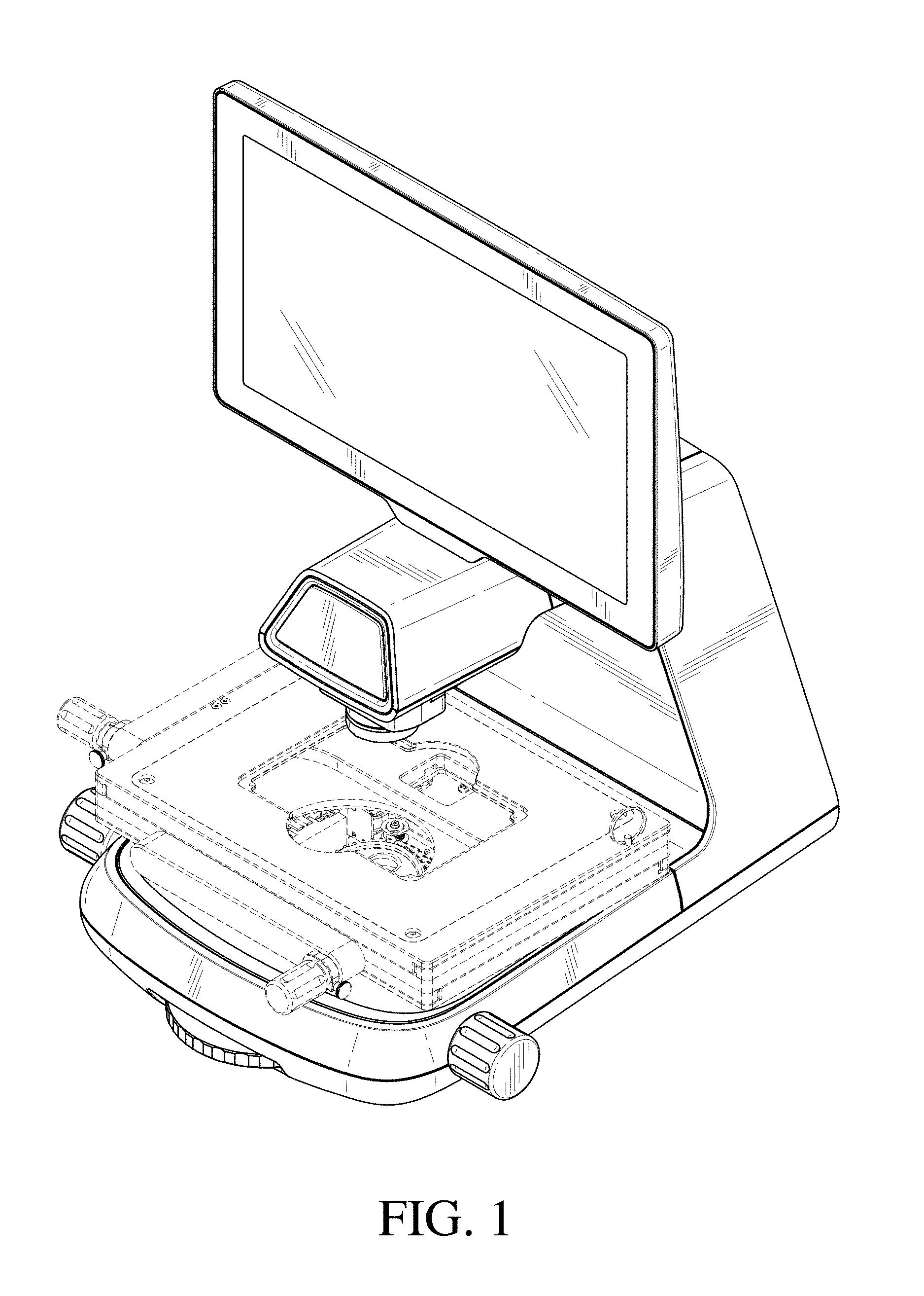
FIG. 1 is a front perspective view of a microscope housing showing our new design with the monitor in a vertical state;
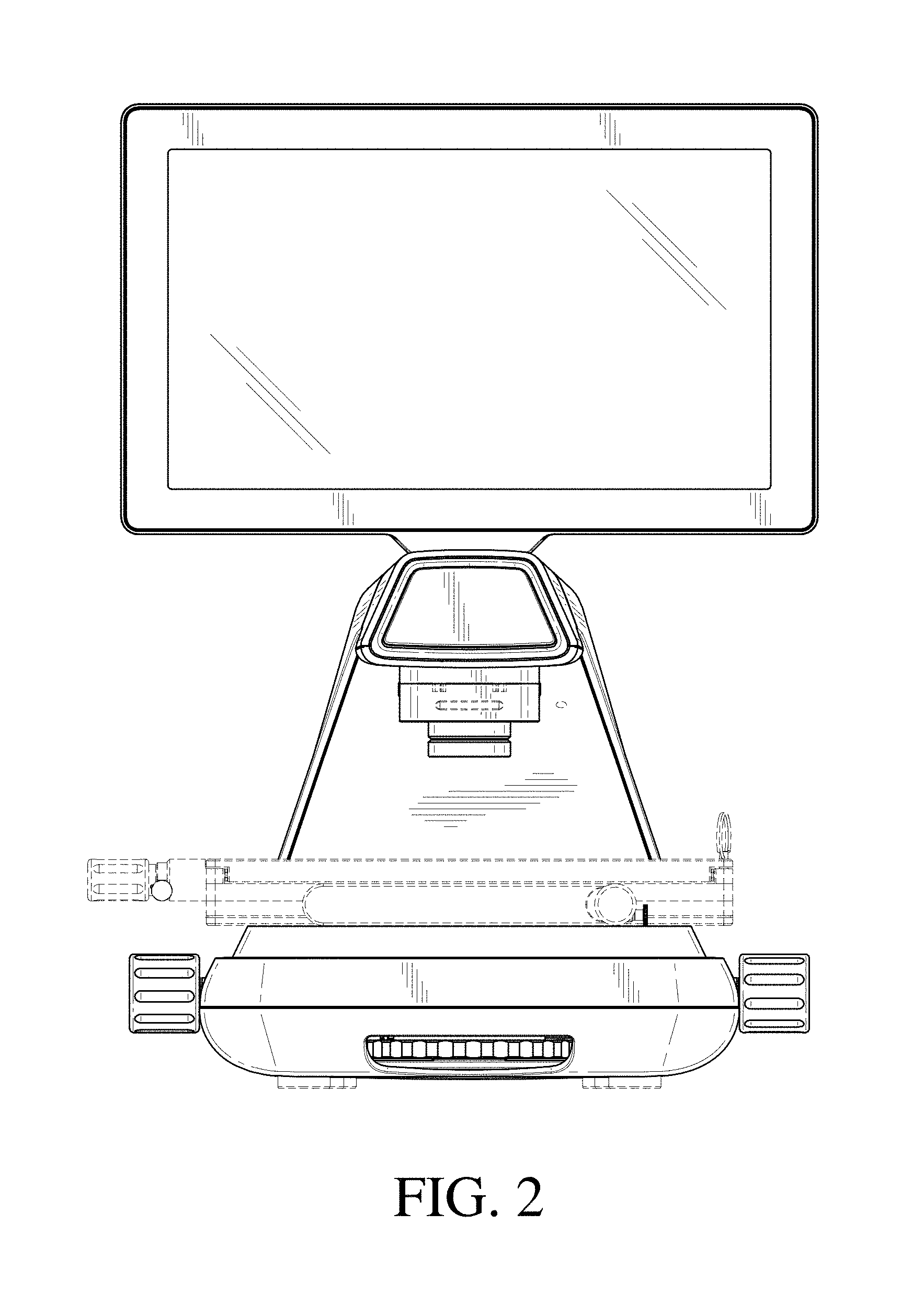
FIG. 2 is a front view thereof;
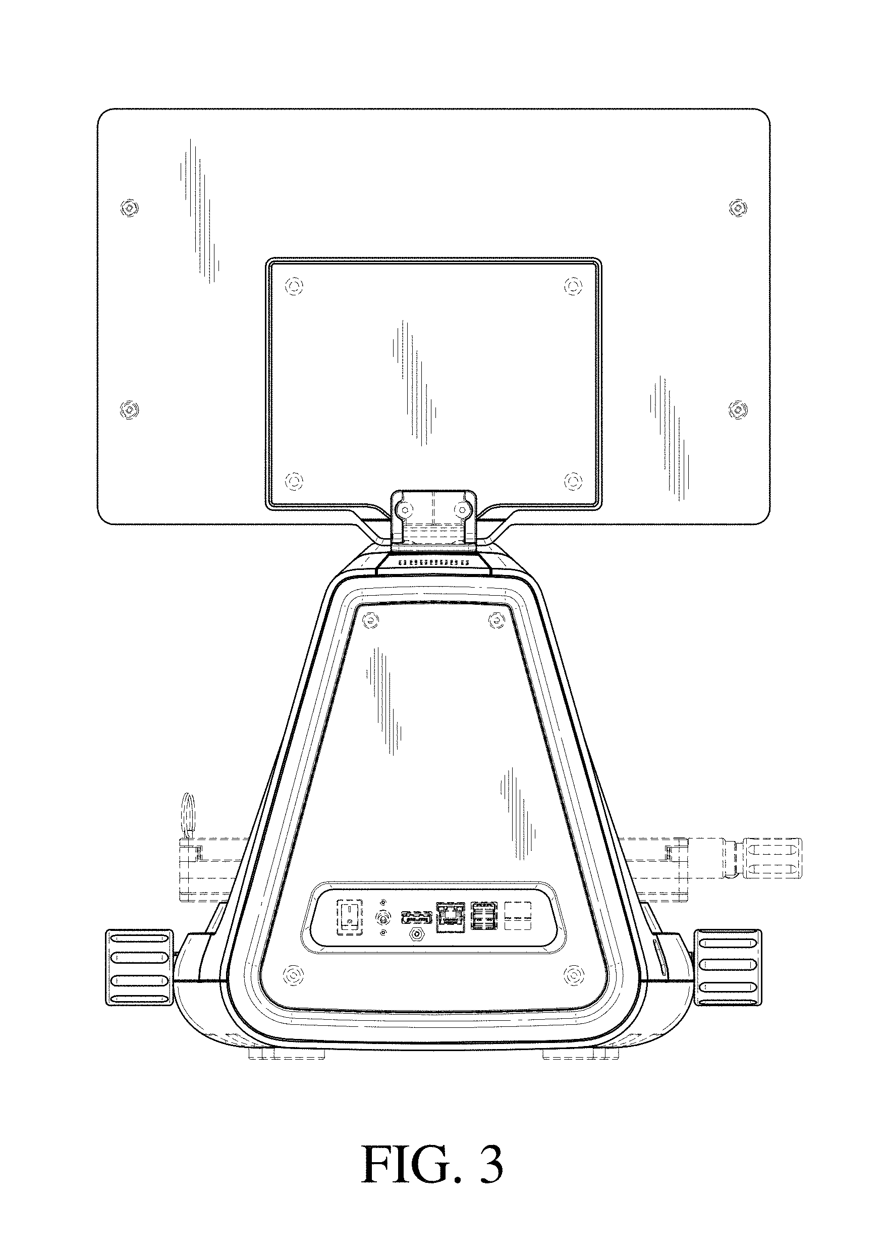
FIG. 3 is a rear view thereof;
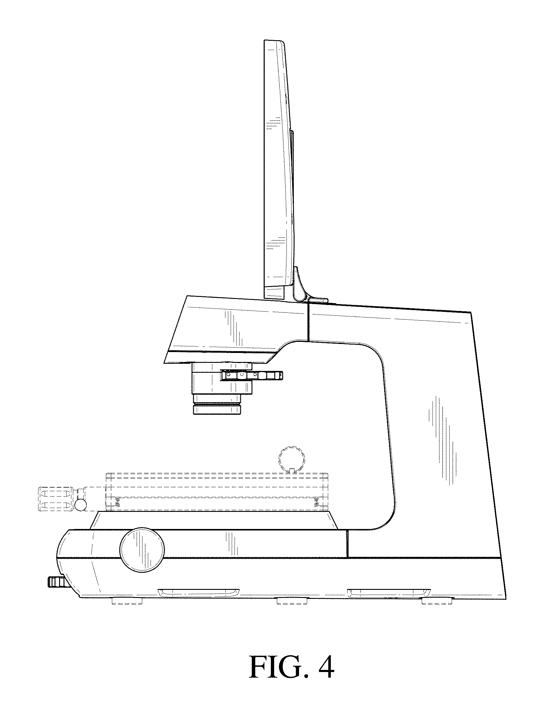
FIG. 4 is a right side view thereof;
FIG. 5 is a left side view thereof;
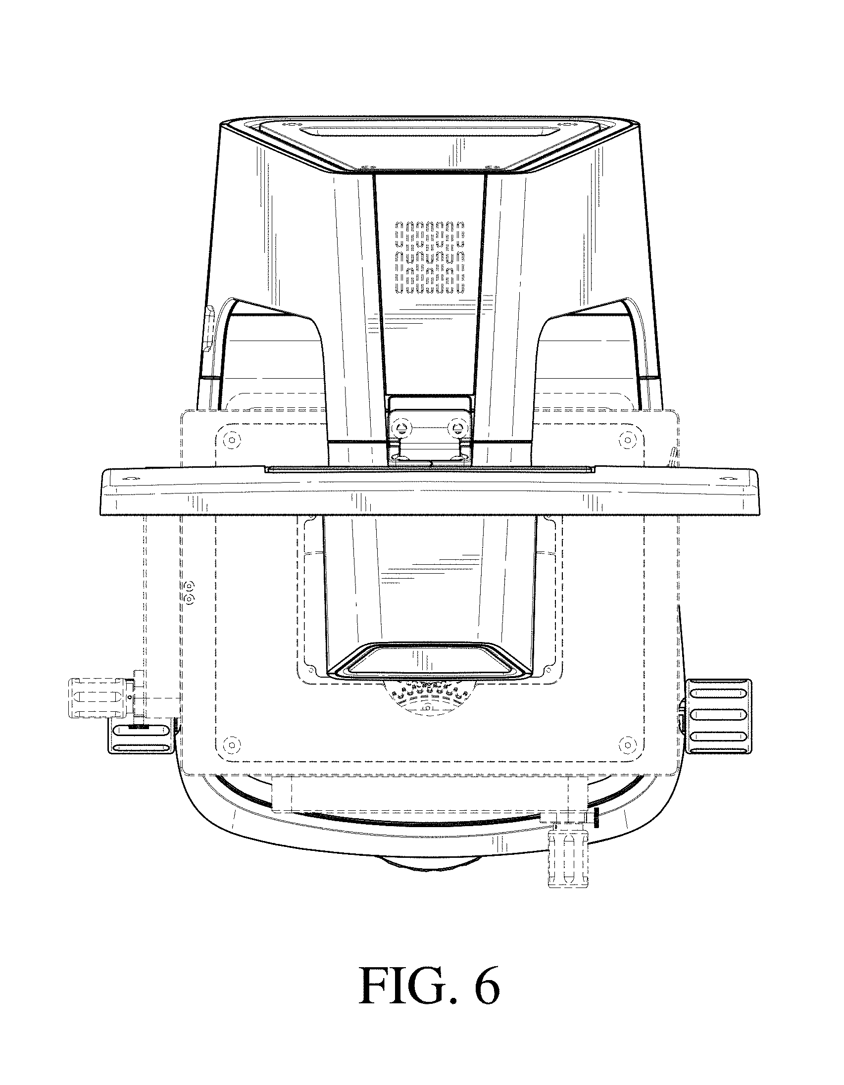
FIG. 6 is a top view thereof;
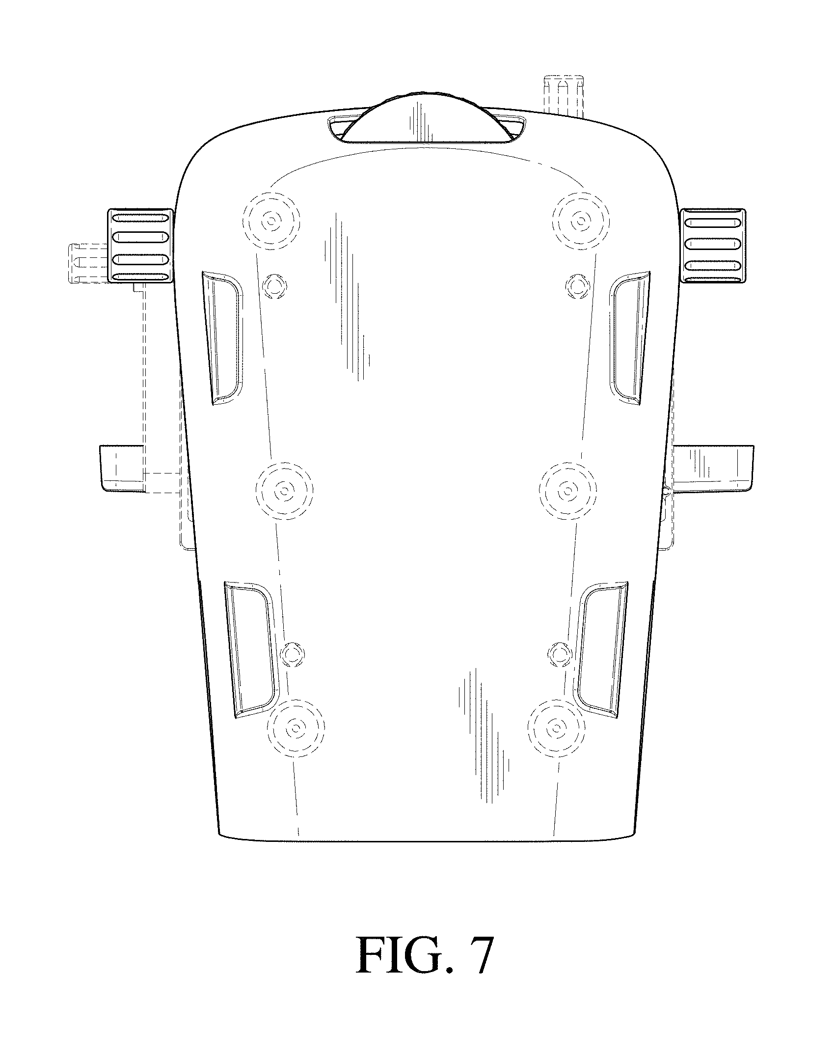
FIG. 7 is a bottom view thereof;
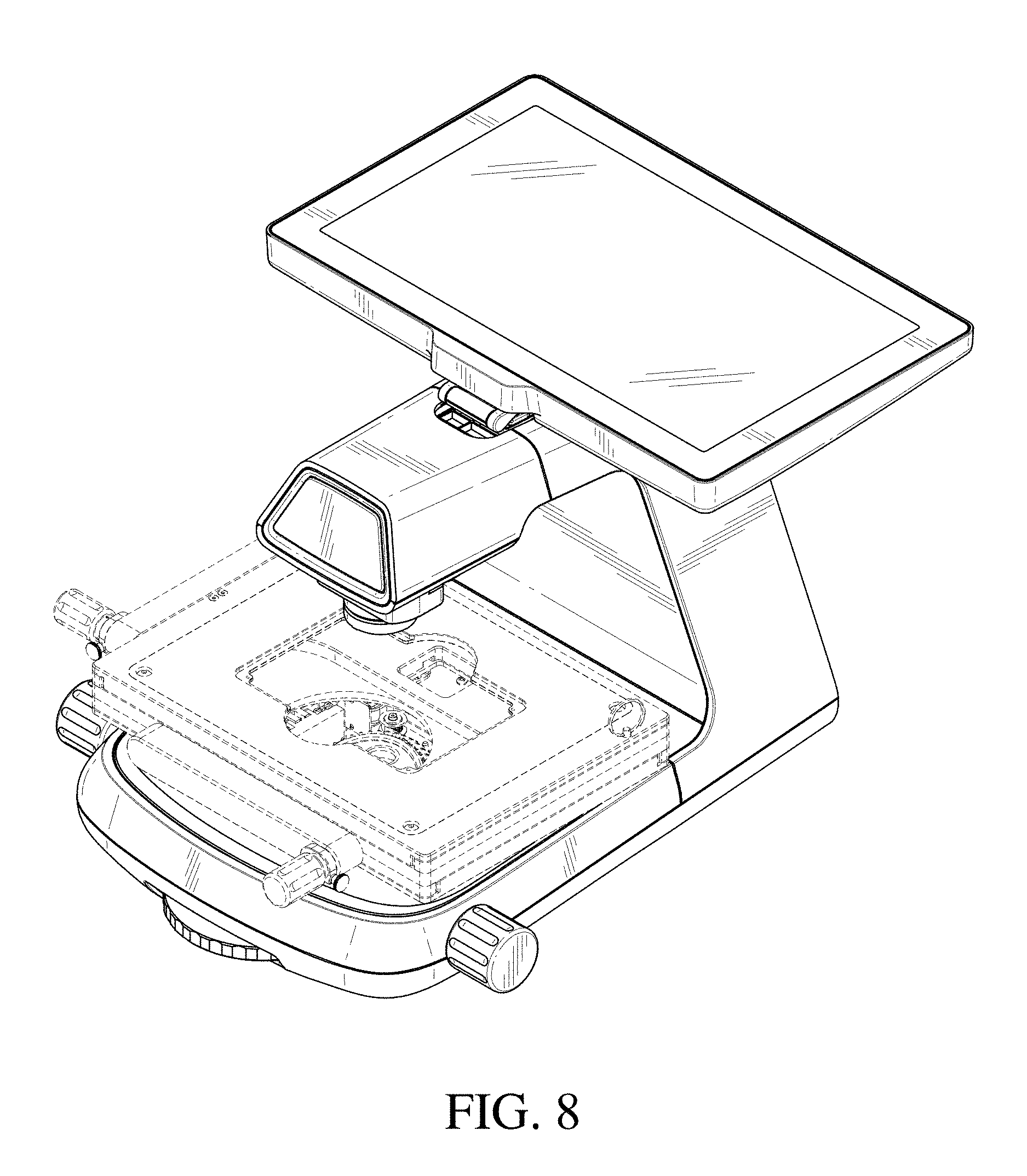
FIG. 8 is a front perspective view of the microscope housing of FIG. 1, showing the monitor in a horizontal state;
FIG. 9 is a front perspective view of the microscope housing of FIG. 1, showing the monitor in a vertical state; the top three layers of the unclaimed platform are moved to the side;
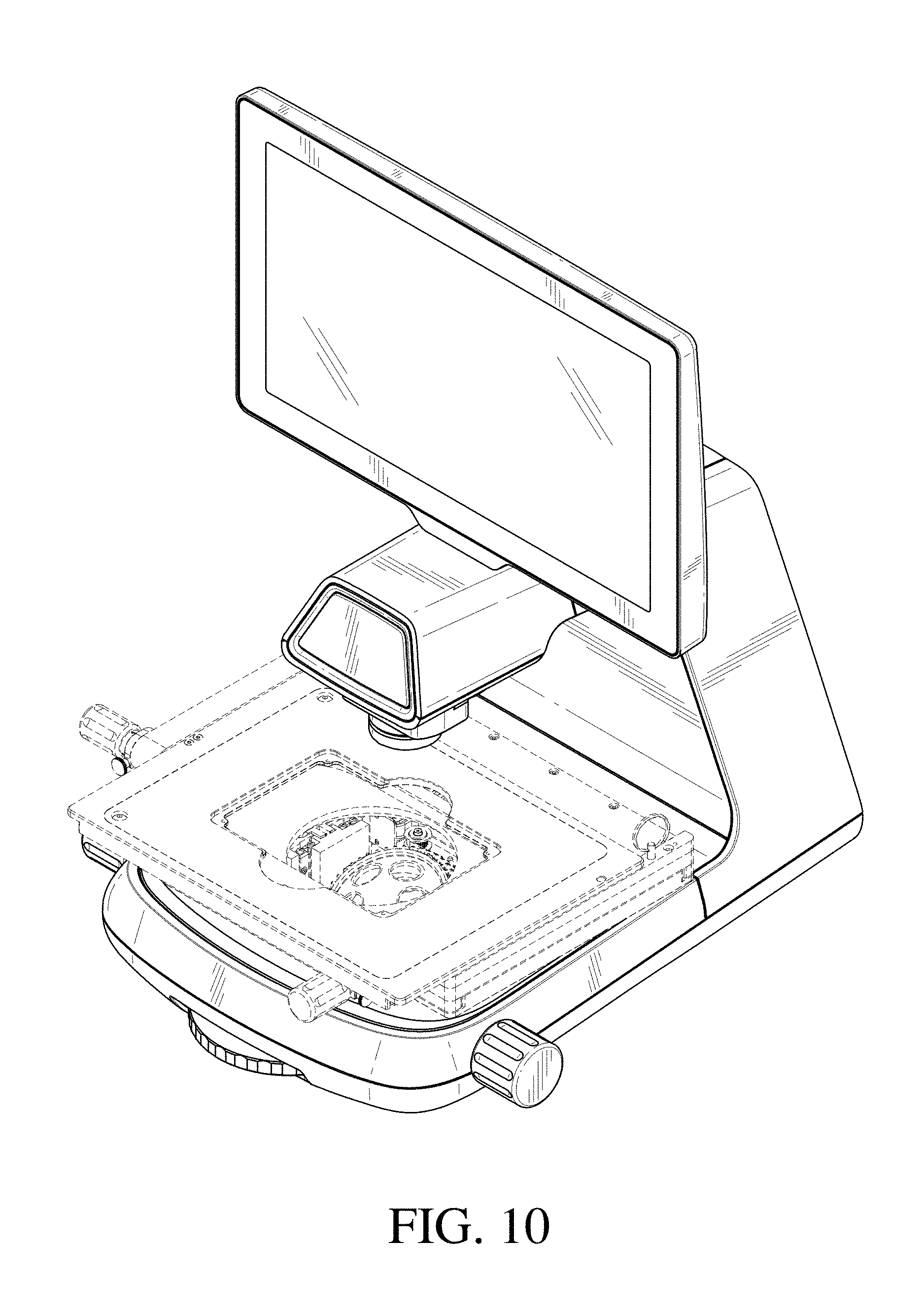
FIG. 10 is a front perspective view thereof with the top layer of the platform positioned to the front; and,
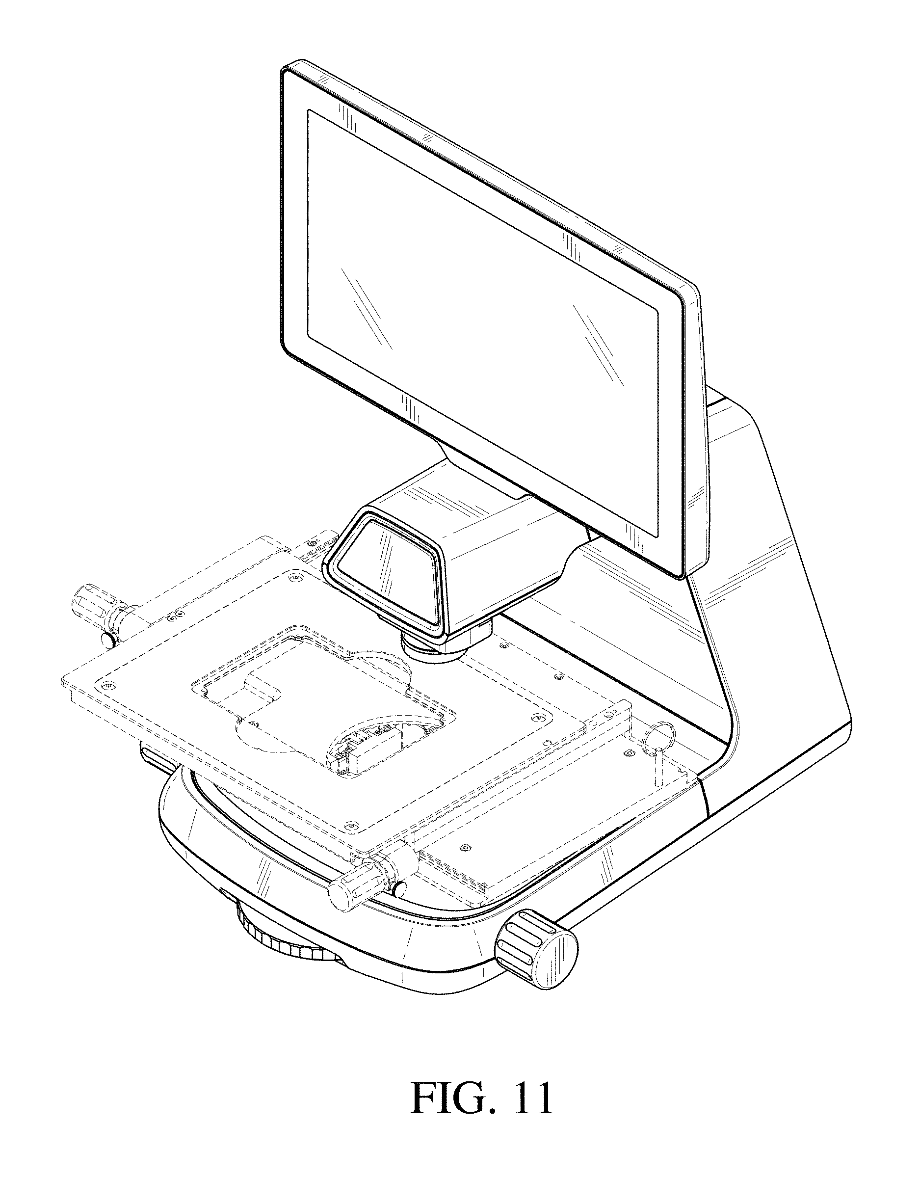
FIG. 11 is a front perspective view thereof with the top three layers of the platform moved to the side and the very top layer of the platform positioned in the front.
The broken lines in the drawings depict portions of the microscope housing that form no part of the claimed design.
* * * * *
References
D00000
D00001
D00002
D00003
D00004
D00005
D00006
D00007
D00008
D00009
D00010
D00011
XML
uspto.report is an independent third-party trademark research tool that is not affiliated, endorsed, or sponsored by the United States Patent and Trademark Office (USPTO) or any other governmental organization. The information provided by uspto.report is based on publicly available data at the time of writing and is intended for informational purposes only.
While we strive to provide accurate and up-to-date information, we do not guarantee the accuracy, completeness, reliability, or suitability of the information displayed on this site. The use of this site is at your own risk. Any reliance you place on such information is therefore strictly at your own risk.
All official trademark data, including owner information, should be verified by visiting the official USPTO website at www.uspto.gov. This site is not intended to replace professional legal advice and should not be used as a substitute for consulting with a legal professional who is knowledgeable about trademark law.