Blade cartridge tray
Levy J
U.S. patent number D837,068 [Application Number D/621,905] was granted by the patent office on 2019-01-01 for blade cartridge tray. This patent grant is currently assigned to DD KARMA LLC. The grantee listed for this patent is DD Karma LLC. Invention is credited to Dara Levy.


| United States Patent | D837,068 |
| Levy | January 1, 2019 |
Blade cartridge tray
Claims
CLAIM The ornamental design for a blade cartridge tray, as shown and described.
| Inventors: | Levy; Dara (Highland Park, IL) | ||||||||||
|---|---|---|---|---|---|---|---|---|---|---|---|
| Applicant: |
|
||||||||||
| Assignee: | DD KARMA LLC (Highland Park,
IL) |
||||||||||
| Appl. No.: | D/621,905 | ||||||||||
| Filed: | October 12, 2017 |
| Current U.S. Class: | D9/736; D9/749 |
| Current International Class: | 0903 |
| Field of Search: | ;D9/737,748,749,735,736 ;D6/512,526 ;D3/201,205 ;D7/555 |
References Cited [Referenced By]
U.S. Patent Documents
| 2796742 | June 1957 | Platt |
| 3342397 | September 1967 | Duitsman |
| D219645 | January 1971 | Rabe |
| 4009817 | March 1977 | Marshall |
| D256997 | September 1980 | Motta |
| D262189 | December 1981 | Swatek |
| D353302 | December 1994 | Fish |
| D353764 | December 1994 | Ho |
| D354197 | January 1995 | Fish |
| D358761 | May 1995 | Ho |
| D366611 | January 1996 | Poisson |
| D428809 | August 2000 | Adair |
| D596047 | July 2009 | Wonderley |
| D636219 | April 2011 | Cornu |
| D643751 | August 2011 | Wonderley |
| D752392 | March 2016 | Maas |
| D779270 | February 2017 | Hogan |
| D801193 | October 2017 | Vorobej |
| D824269 | July 2018 | Vorobej |
| 2004/0222228 | November 2004 | Price |
| 2013/0108523 | May 2013 | Tawfik |
| 2016/0166273 | June 2016 | Levy |
| 2016/0318682 | November 2016 | Vorobej |
| 2018/0215529 | August 2018 | Bergeron |
Other References
|
[No Author Listed] Photo of Dermaflash.RTM. Cartridge Blade Tray. http://www.dermaflash.com/ [last accessed Oct. 19, 2017]. cited by applicant. |
Primary Examiner: Calve; Lauren R
Attorney, Agent or Firm: Wolf, Greenfield & Sacks, P.C.
Description
FIG. 1 is a rear elevation view of a blade cartridge tray;
FIG. 2 is a bottom plan view thereof;
FIG. 3 is a top, left, perspective view thereof;
FIG. 4 is a front elevation view thereof;
FIG. 5 is a right side view thereof; and
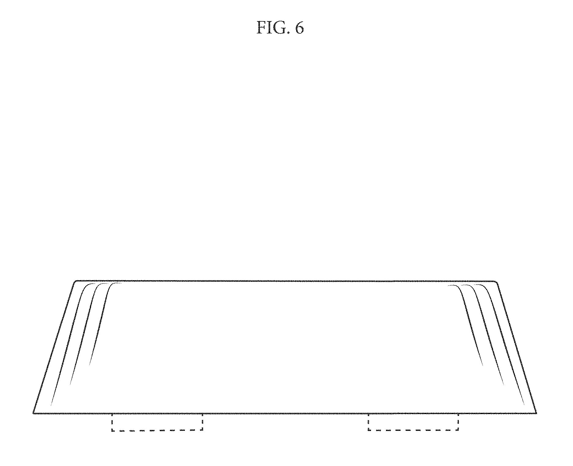
FIG. 6 is a left side view thereof; and,
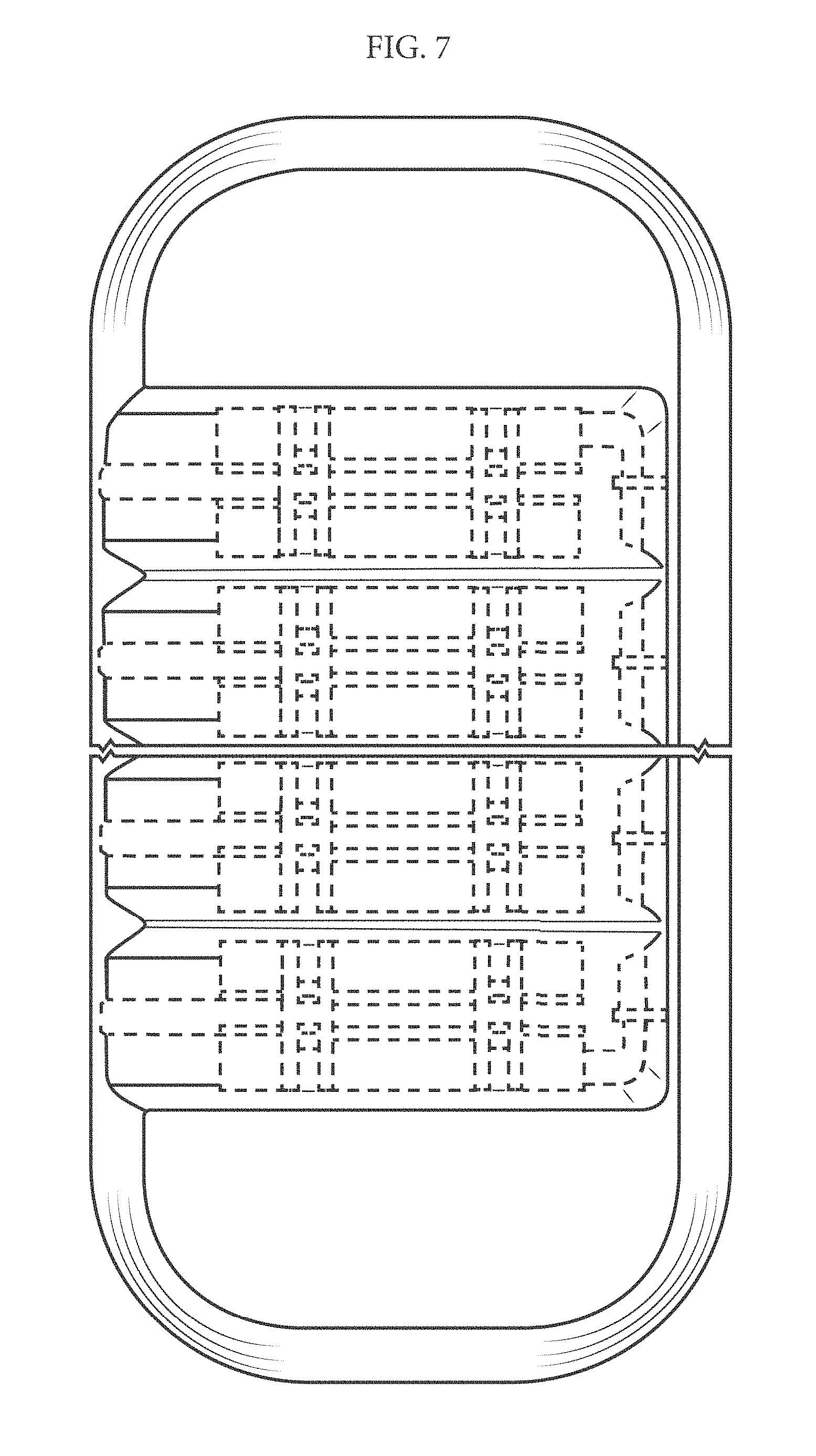
FIG. 7 is a top plan view thereof.
The dash-dot-dash broken lines define boundaries of the blade cartridge tray and form no part of the claimed design. All other broken lines shown are included for illustrative purposes only and represent portion of the blade cartridge tray that form no part of the claimed design. The pairs of brackets adjacent break lines form no part of the claimed design, and indicate that the appearance of any portion of the blade cartridge tray between the break lines forms no part of the claimed design.
* * * * *
References
D00000
D00001
D00002
D00003
D00004
D00005
D00006
D00007
XML
uspto.report is an independent third-party trademark research tool that is not affiliated, endorsed, or sponsored by the United States Patent and Trademark Office (USPTO) or any other governmental organization. The information provided by uspto.report is based on publicly available data at the time of writing and is intended for informational purposes only.
While we strive to provide accurate and up-to-date information, we do not guarantee the accuracy, completeness, reliability, or suitability of the information displayed on this site. The use of this site is at your own risk. Any reliance you place on such information is therefore strictly at your own risk.
All official trademark data, including owner information, should be verified by visiting the official USPTO website at www.uspto.gov. This site is not intended to replace professional legal advice and should not be used as a substitute for consulting with a legal professional who is knowledgeable about trademark law.