Spinal correction and secondary stabilization
Seme , et al. December 30, 2
U.S. patent number 8,920,472 [Application Number 13/865,775] was granted by the patent office on 2014-12-30 for spinal correction and secondary stabilization. This patent grant is currently assigned to Kspine, Inc.. The grantee listed for this patent is Kspine, Inc.. Invention is credited to Thomas J. Gisel, John F. Otte, Steven J. Seme.


View All Diagrams
| United States Patent | 8,920,472 |
| Seme , et al. | December 30, 2014 |
Spinal correction and secondary stabilization
Abstract
Methods of correcting a spinal deformity include securing a first rod on a first side of a spine, securing an anchor on a second side of a spine, securing a lateral coupling between the rod and the anchor, translating and derotating the spine to correct the spinal deformity by adjusting an effective length of the lateral coupling, and securing a second rod on a second side of the spine to provide secondary stabilization to the spine.
| Inventors: | Seme; Steven J. (Savage, MN), Otte; John F. (Minneapolis, MN), Gisel; Thomas J. (Chaska, MN) | ||||||||||
|---|---|---|---|---|---|---|---|---|---|---|---|
| Applicant: |
|
||||||||||
| Assignee: | Kspine, Inc. (Minnetonka,
MN) |
||||||||||
| Family ID: | 56291312 | ||||||||||
| Appl. No.: | 13/865,775 | ||||||||||
| Filed: | April 18, 2013 |
Prior Publication Data
| Document Identifier | Publication Date | |
|---|---|---|
| US 20130231703 A1 | Sep 5, 2013 | |
Related U.S. Patent Documents
| Application Number | Filing Date | Patent Number | Issue Date | ||
|---|---|---|---|---|---|
| 13297841 | Nov 16, 2011 | ||||
| Current U.S. Class: | 606/251; 606/250 |
| Current CPC Class: | A61B 17/7046 (20130101); A61B 17/7044 (20130101); A61B 17/705 (20130101); A61B 17/7052 (20130101); A61B 17/7001 (20130101); A61B 17/7049 (20130101); A61B 17/8869 (20130101); A61B 17/701 (20130101); A61B 17/7019 (20130101); A61B 17/7041 (20130101); A61B 17/7002 (20130101); A61B 17/707 (20130101); A61B 17/70 (20130101); A61B 17/7004 (20130101); A61B 17/7053 (20130101); A61B 17/704 (20130101) |
| Current International Class: | A61B 17/70 (20060101) |
| Field of Search: | ;606/250-253,256-257 |
References Cited [Referenced By]
U.S. Patent Documents
| 2774350 | December 1956 | Cleveland, Jr. |
| 3242922 | March 1966 | Thomas |
| 3352226 | November 1967 | Nelsen |
| 3648691 | March 1972 | Lumb et al. |
| 3693616 | September 1972 | Roaf et al. |
| 3865105 | February 1975 | Lode |
| 4024588 | May 1977 | Janssen et al. |
| 4078559 | March 1978 | Nissinen |
| 4257409 | March 1981 | Bacal et al. |
| 4269178 | May 1981 | Keene |
| 4274401 | June 1981 | Miskew |
| 4355645 | October 1982 | Mitani et al. |
| 4361141 | November 1982 | Tanner |
| 4369769 | January 1983 | Edwards |
| 4404967 | September 1983 | Bacal et al. |
| 4411259 | October 1983 | Drummond |
| 4411545 | October 1983 | Roberge |
| 4448191 | May 1984 | Rodnyansky et al. |
| 4505268 | March 1985 | Sgandurra |
| 4554914 | November 1985 | Kapp et al. |
| 4573454 | March 1986 | Hoffman |
| 4604995 | August 1986 | Stephens et al. |
| 4611581 | September 1986 | Steffee |
| 4611582 | September 1986 | Duff |
| 4634445 | January 1987 | Helal |
| 4648388 | March 1987 | Steffee |
| 4653481 | March 1987 | Howland et al. |
| 4658809 | April 1987 | Ulrich et al. |
| 4697582 | October 1987 | William |
| 4738251 | April 1988 | Plaza |
| 4773402 | September 1988 | Asher et al. |
| 4805602 | February 1989 | Puno et al. |
| 4815453 | March 1989 | Cotrel |
| 4827918 | May 1989 | Olerud |
| 4854311 | August 1989 | Steffee |
| 4931055 | June 1990 | Bumpus et al. |
| 4936848 | June 1990 | Bagby |
| 5000166 | March 1991 | Karpf |
| 5005562 | April 1991 | Cotrel |
| 5011484 | April 1991 | Breard |
| 5030220 | July 1991 | Howland |
| 5042982 | August 1991 | Harms et al. |
| 5084049 | January 1992 | Asher et al. |
| 5092866 | March 1992 | Breard et al. |
| 5092867 | March 1992 | Harms et al. |
| 5127912 | July 1992 | Ray et al. |
| 5129900 | July 1992 | Asher et al. |
| 5133716 | July 1992 | Plaza |
| 5147363 | September 1992 | Harle |
| 5176679 | January 1993 | Lin |
| 5176680 | January 1993 | Vignaud et al. |
| 5181917 | January 1993 | Rogozinski |
| 5190543 | March 1993 | Schlapfer |
| 5196014 | March 1993 | Lin |
| 5207678 | May 1993 | Harms et al. |
| 5209752 | May 1993 | Ashman et al. |
| 5219349 | June 1993 | Krag et al. |
| 5242443 | September 1993 | Kambin |
| 5254118 | October 1993 | Mirkovic |
| 5257994 | November 1993 | Lin |
| 5259398 | November 1993 | Vrespa |
| 5282862 | February 1994 | Baker et al. |
| 5306275 | April 1994 | Bryan |
| 5312404 | May 1994 | Asher et al. |
| 5312410 | May 1994 | Miller et al. |
| 5312420 | May 1994 | Toso et al. |
| 5330473 | July 1994 | Howland |
| 5330474 | July 1994 | Lin |
| 5352226 | October 1994 | Lin |
| 5360431 | November 1994 | Puno et al. |
| 5366455 | November 1994 | Dove et al. |
| 5368594 | November 1994 | Martin et al. |
| 5380323 | January 1995 | Howland |
| 5380325 | January 1995 | Lahille et al. |
| 5382248 | January 1995 | Jacobson et al. |
| 5387212 | February 1995 | Yuan et al. |
| 5387213 | February 1995 | Breard et al. |
| 5391168 | February 1995 | Sanders et al. |
| 5397363 | March 1995 | Gelbard |
| 5413576 | May 1995 | Rivard |
| 5436542 | July 1995 | Petelin et al. |
| 5437669 | August 1995 | Yuan et al. |
| 5437671 | August 1995 | Lozier et al. |
| 5456722 | October 1995 | McLeod et al. |
| 5466238 | November 1995 | Lin |
| 5470333 | November 1995 | Ray |
| 5480440 | January 1996 | Kambin |
| 5486174 | January 1996 | Fournet Fayard et al. |
| 5487744 | January 1996 | Howland |
| 5490851 | February 1996 | Nenov et al. |
| 5496318 | March 1996 | Howland et al. |
| 5498262 | March 1996 | Bryan |
| 5501684 | March 1996 | Schlapfer et al. |
| 5520688 | May 1996 | Lin |
| 5527314 | June 1996 | Brumfield et al. |
| 5534002 | July 1996 | Brumfield et al. |
| 5540689 | July 1996 | Sanders et al. |
| 5544993 | August 1996 | Harle |
| 5549679 | August 1996 | Kuslich |
| 5562660 | October 1996 | Grob |
| 5562662 | October 1996 | Brumfield et al. |
| 5569246 | October 1996 | Ojima et al. |
| 5571191 | November 1996 | Fitz |
| 5575791 | November 1996 | Lin |
| 5584626 | December 1996 | Assmundson |
| 5586983 | December 1996 | Sanders et al. |
| 5591165 | January 1997 | Jackson |
| 5601554 | February 1997 | Howland et al. |
| 5609592 | March 1997 | Brumfield et al. |
| 5611800 | March 1997 | Davis et al. |
| 5620443 | April 1997 | Gertzbein et al. |
| 5630816 | May 1997 | Kambin |
| 5643259 | July 1997 | Sasso et al. |
| 5645599 | July 1997 | Samani |
| 5649926 | July 1997 | Howland |
| 5658284 | August 1997 | Sebastian et al. |
| 5672175 | September 1997 | Martin |
| 5676703 | October 1997 | Gelbard |
| 5702395 | December 1997 | Hopf |
| 5702399 | December 1997 | Kilpela et al. |
| 5702452 | December 1997 | Argenson et al. |
| 5704936 | January 1998 | Mazel |
| 5713898 | February 1998 | Stucker et al. |
| 5716355 | February 1998 | Jackson et al. |
| 5725582 | March 1998 | Bevan et al. |
| 5728097 | March 1998 | Mathews |
| 5733284 | March 1998 | Martin |
| 5735852 | April 1998 | Amrein et al. |
| 5782831 | July 1998 | Sherman et al. |
| 5797910 | August 1998 | Martin |
| 5810817 | September 1998 | Roussouly et al. |
| 5810819 | September 1998 | Errico et al. |
| 5814046 | September 1998 | Hopf |
| 5885285 | March 1999 | Simonson |
| 5891145 | April 1999 | Morrison et al. |
| 5902305 | May 1999 | Beger et al. |
| 5910142 | June 1999 | Tatar |
| 5928232 | July 1999 | Howland et al. |
| 5938663 | August 1999 | Petreto |
| 5947967 | September 1999 | Barker |
| 5964769 | October 1999 | Wagner et al. |
| 5976135 | November 1999 | Sherman et al. |
| 5980521 | November 1999 | Montague et al. |
| 5984924 | November 1999 | Asher et al. |
| 5989256 | November 1999 | Kuslich et al. |
| 6015409 | January 2000 | Jackson |
| 6033412 | March 2000 | Losken et al. |
| 6039738 | March 2000 | Sanders et al. |
| 6053921 | April 2000 | Wagner et al. |
| 6066140 | May 2000 | Gertzbein et al. |
| 6077268 | June 2000 | Farris et al. |
| 6080156 | June 2000 | Asher et al. |
| 6083224 | July 2000 | Gertzbein et al. |
| 6086590 | July 2000 | Margulies et al. |
| 6101678 | August 2000 | Malloy et al. |
| 6110173 | August 2000 | Thomas, Jr. |
| 6123706 | September 2000 | Lange |
| 6132431 | October 2000 | Nilsson et al. |
| 6132464 | October 2000 | Martin |
| 6136000 | October 2000 | Louis et al. |
| 6176861 | January 2001 | Bernstein et al. |
| 6231575 | May 2001 | Krag |
| 6248106 | June 2001 | Ferree |
| 6251111 | June 2001 | Barker et al. |
| 6254603 | July 2001 | Gertzbein et al. |
| 6261288 | July 2001 | Jackson |
| 6273914 | August 2001 | Papas |
| 6277120 | August 2001 | Lawson |
| 6283967 | September 2001 | Troxell et al. |
| 6293949 | September 2001 | Justis et al. |
| 6296643 | October 2001 | Hopf et al. |
| 6299613 | October 2001 | Ogilvie et al. |
| 6325805 | December 2001 | Ogilvie et al. |
| 6328739 | December 2001 | Liu et al. |
| 6358254 | March 2002 | Anderson |
| 6364883 | April 2002 | Santilli |
| 6364885 | April 2002 | Kilpela et al. |
| 6391030 | May 2002 | Wagner et al. |
| 6402749 | June 2002 | Ashman |
| 6402752 | June 2002 | Schaffler Wachter et al. |
| 6419703 | July 2002 | Fallin et al. |
| 6423065 | July 2002 | Ferree |
| 6451019 | September 2002 | Zucherman et al. |
| 6458131 | October 2002 | Ray |
| 6471704 | October 2002 | Gertzbein et al. |
| 6488683 | December 2002 | Lieberman |
| 6514255 | February 2003 | Ferree |
| 6520962 | February 2003 | Taylor et al. |
| 6537276 | March 2003 | Metz Stavenhagen |
| 6547789 | April 2003 | Ventre et al. |
| 6551320 | April 2003 | Lieberman |
| 6554831 | April 2003 | Rivard et al. |
| 6562038 | May 2003 | Morrison |
| 6565569 | May 2003 | Assaker et al. |
| 6565605 | May 2003 | Goble et al. |
| 6569164 | May 2003 | Assaker et al. |
| 6579292 | June 2003 | Taylor |
| 6579319 | June 2003 | Goble et al. |
| 6582433 | June 2003 | Yun |
| 6585738 | July 2003 | Mangione et al. |
| 6589243 | July 2003 | Viart et al. |
| 6602254 | August 2003 | Gertzbein et al. |
| 6602818 | August 2003 | Choi et al. |
| 6610091 | August 2003 | Reiley |
| 6616669 | September 2003 | Ogilvie et al. |
| 6623484 | September 2003 | Betz et al. |
| 6626906 | September 2003 | Young |
| 6626909 | September 2003 | Chin |
| 6641585 | November 2003 | Sato et al. |
| 6645207 | November 2003 | Dixon et al. |
| 6651320 | November 2003 | Yagi et al. |
| 6656185 | December 2003 | Gleason et al. |
| 6669729 | December 2003 | Chin |
| 6682532 | January 2004 | Johnson et al. |
| 6682533 | January 2004 | Dinsdale et al. |
| 6685705 | February 2004 | Taylor |
| 6689133 | February 2004 | Morrison et al. |
| 6709435 | March 2004 | Lin |
| 6736817 | May 2004 | Troxell et al. |
| 6749612 | June 2004 | Conchy et al. |
| 6755828 | June 2004 | Shevtsov et al. |
| 6773437 | August 2004 | Ogilvie et al. |
| 6802844 | October 2004 | Ferree |
| 6811567 | November 2004 | Reiley |
| 6835207 | December 2004 | Zacouto et al. |
| 6840127 | January 2005 | Moran |
| 6860884 | March 2005 | Shirado et al. |
| 6887241 | May 2005 | McBride et al. |
| 6902580 | June 2005 | Fallin et al. |
| 6946000 | September 2005 | Senegas et al. |
| 6966910 | November 2005 | Ritland |
| 6966930 | November 2005 | Arnin et al. |
| 6974478 | December 2005 | Reiley et al. |
| 6986771 | January 2006 | Paul et al. |
| 7008423 | March 2006 | Assaker et al. |
| 7018379 | March 2006 | Drewry et al. |
| 7029475 | April 2006 | Panjabi |
| 7041136 | May 2006 | Goble et al. |
| 7048736 | May 2006 | Robinson et al. |
| 7051451 | May 2006 | Augostino et al. |
| 7074237 | July 2006 | Goble et al. |
| 7083621 | August 2006 | Shaolian et al. |
| 7087056 | August 2006 | Vaughan |
| 7090698 | August 2006 | Goble et al. |
| 7104992 | September 2006 | Bailey |
| RE39325 | October 2006 | Bryan |
| 7128743 | October 2006 | Metz Stavenhagen |
| 7137986 | November 2006 | Troxell et al. |
| 7160312 | January 2007 | Saadat |
| 7220262 | May 2007 | Hynes |
| 7261714 | August 2007 | Richelsoph |
| 7270665 | September 2007 | Morrison et al. |
| 7290347 | November 2007 | Augostino et al. |
| 7294129 | November 2007 | Hawkins et al. |
| 7316684 | January 2008 | Baccelli et al. |
| 7335203 | February 2008 | Winslow et al. |
| 7338490 | March 2008 | Ogilvie et al. |
| 7344539 | March 2008 | Serhan et al. |
| 7361196 | April 2008 | Fallin et al. |
| 7367978 | May 2008 | Drewry et al. |
| 7406775 | August 2008 | Funk et al. |
| 7445635 | November 2008 | Fallin et al. |
| 7473267 | January 2009 | Nguyen et al. |
| 7473269 | January 2009 | Hynes |
| 7481828 | January 2009 | Mazda et al. |
| 7507242 | March 2009 | Triplett et al. |
| 7524324 | April 2009 | Winslow et al. |
| 7566345 | July 2009 | Fallin et al. |
| 7588578 | September 2009 | Triplett et al. |
| 7588590 | September 2009 | Chervitz et al. |
| 7591836 | September 2009 | Dick et al. |
| 7594924 | September 2009 | Albert et al. |
| 7611526 | November 2009 | Carl et al. |
| 7618453 | November 2009 | Goble et al. |
| 7618455 | November 2009 | Goble et al. |
| 7621955 | November 2009 | Goble et al. |
| 7648521 | January 2010 | Hestad |
| 7658753 | February 2010 | Carl et al. |
| 7674293 | March 2010 | Kuiper et al. |
| 7678136 | March 2010 | Doubler et al. |
| 7691145 | April 2010 | Reiley et al. |
| 7708762 | May 2010 | McCarthy et al. |
| 7717940 | May 2010 | Woods et al. |
| 7717942 | May 2010 | Schumacher |
| 7722647 | May 2010 | Wang et al. |
| 7722648 | May 2010 | Drewry et al. |
| 7753937 | July 2010 | Chervitz et al. |
| 7758581 | July 2010 | Chervitz et al. |
| 7771474 | August 2010 | Cordaro |
| 7794476 | September 2010 | Wisnewski |
| 7794478 | September 2010 | Nilsson |
| 7799054 | September 2010 | Kwak et al. |
| 7819902 | October 2010 | Abdelgany et al. |
| 7833252 | November 2010 | Justis et al. |
| 7837714 | November 2010 | Drewry et al. |
| 7842071 | November 2010 | Hawkes |
| 7862586 | January 2011 | Malek |
| 7896906 | March 2011 | Kwak et al. |
| 7918876 | April 2011 | Mueller et al. |
| 7927359 | April 2011 | Trautwein et al. |
| 7931676 | April 2011 | Veldman et al. |
| 7935134 | May 2011 | Reglos et al. |
| 7942902 | May 2011 | Schwab |
| 7959653 | June 2011 | Thramann et al. |
| 7963978 | June 2011 | Winslow et al. |
| 7985243 | July 2011 | Winslow et al. |
| 8012184 | September 2011 | Schlapfer et al. |
| 8016860 | September 2011 | Carl et al. |
| 8021400 | September 2011 | Marino et al. |
| 8029543 | October 2011 | Young et al. |
| 8029546 | October 2011 | Capote et al. |
| 8034078 | October 2011 | Laskowitz et al. |
| 8034084 | October 2011 | Landry et al. |
| 8043345 | October 2011 | Carl et al. |
| 8048113 | November 2011 | Winslow et al. |
| 8052722 | November 2011 | Winslow et al. |
| 8066743 | November 2011 | Young et al. |
| 8070775 | December 2011 | Winslow et al. |
| 8070776 | December 2011 | Winslow et al. |
| 8075594 | December 2011 | Purcell |
| 8097022 | January 2012 | Marik |
| 8114134 | February 2012 | Winslow et al. |
| 8114158 | February 2012 | Carl et al. |
| 8118837 | February 2012 | Lemoine |
| 8147524 | April 2012 | Piza Vallespir |
| 8162979 | April 2012 | Sachs et al. |
| 8167908 | May 2012 | Ely et al. |
| 8192471 | June 2012 | Ludwig et al. |
| 8221466 | July 2012 | Asaad et al. |
| 8262696 | September 2012 | Falahee |
| 8292934 | October 2012 | Justis et al. |
| 8323319 | December 2012 | Mazda et al. |
| 8353934 | January 2013 | Drewry et al. |
| 8357182 | January 2013 | Seme |
| 8357183 | January 2013 | Seme et al. |
| 8361117 | January 2013 | Michielli et al. |
| 8403958 | March 2013 | Schwab |
| 8414614 | April 2013 | Firkins et al. |
| 8414617 | April 2013 | Young et al. |
| 8470001 | June 2013 | Trautwein et al. |
| RE44392 | July 2013 | Hynes |
| 8475499 | July 2013 | Cournoyer et al. |
| 8480712 | July 2013 | Samuel et al. |
| 8518086 | August 2013 | Seme et al. |
| 2001/0037111 | November 2001 | Dixon et al. |
| 2002/0032442 | March 2002 | Altarac et al. |
| 2002/0133155 | September 2002 | Ferree |
| 2002/0143329 | October 2002 | Serhan et al. |
| 2002/0151978 | October 2002 | Zacouto et al. |
| 2003/0040746 | February 2003 | Mitchell et al. |
| 2003/0045878 | March 2003 | Petit et al. |
| 2003/0093117 | May 2003 | Saadat |
| 2003/0109881 | June 2003 | Shirado et al. |
| 2003/0114853 | June 2003 | Burgess et al. |
| 2003/0153915 | August 2003 | Nekozuka et al. |
| 2003/0220643 | November 2003 | Ferree |
| 2004/0006391 | January 2004 | Reiley |
| 2004/0049274 | March 2004 | Reiley |
| 2004/0049277 | March 2004 | Reiley |
| 2004/0097931 | May 2004 | Mitchell |
| 2004/0106921 | June 2004 | Cheung et al. |
| 2004/0149065 | August 2004 | Moran |
| 2004/0167520 | August 2004 | Zucherman et al. |
| 2004/0215190 | October 2004 | Nguyen et al. |
| 2004/0230201 | November 2004 | Yuan et al. |
| 2004/0230304 | November 2004 | Yuan et al. |
| 2005/0027361 | February 2005 | Reiley |
| 2005/0033291 | February 2005 | Ebara |
| 2005/0033295 | February 2005 | Wisnewski |
| 2005/0043797 | February 2005 | Lee |
| 2005/0043799 | February 2005 | Reiley |
| 2005/0049705 | March 2005 | Hale et al. |
| 2005/0055096 | March 2005 | Serhan et al. |
| 2005/0080420 | April 2005 | Farris et al. |
| 2005/0080486 | April 2005 | Fallin et al. |
| 2005/0107789 | May 2005 | Sweeney |
| 2005/0113927 | May 2005 | Malek |
| 2005/0113928 | May 2005 | Cragg et al. |
| 2005/0131537 | June 2005 | Hoy et al. |
| 2005/0131538 | June 2005 | Chervitz et al. |
| 2005/0149030 | July 2005 | Serhan et al. |
| 2005/0154390 | July 2005 | Biedermann et al. |
| 2005/0165396 | July 2005 | Fortin et al. |
| 2005/0171538 | August 2005 | Sgier et al. |
| 2005/0177240 | August 2005 | Blain |
| 2005/0203509 | September 2005 | Chinnaian et al. |
| 2005/0203511 | September 2005 | Wilson MacDonald et al. |
| 2005/0203514 | September 2005 | Jahng et al. |
| 2005/0203516 | September 2005 | Biedermann et al. |
| 2005/0209603 | September 2005 | Zucherman et al. |
| 2005/0216004 | September 2005 | Schwab |
| 2005/0228326 | October 2005 | Kalfas et al. |
| 2005/0228377 | October 2005 | Chao et al. |
| 2005/0234453 | October 2005 | Shaolian et al. |
| 2005/0240264 | October 2005 | Tokish et al. |
| 2005/0245929 | November 2005 | Winslow et al. |
| 2005/0261685 | November 2005 | Fortin et al. |
| 2005/0261770 | November 2005 | Kuiper et al. |
| 2005/0267470 | December 2005 | McBride |
| 2005/0267579 | December 2005 | Reiley et al. |
| 2006/0004449 | January 2006 | Goble et al. |
| 2006/0009767 | January 2006 | Kiester |
| 2006/0009847 | January 2006 | Reiley |
| 2006/0009849 | January 2006 | Reiley |
| 2006/0036246 | February 2006 | Carl et al. |
| 2006/0036256 | February 2006 | Carl et al. |
| 2006/0036259 | February 2006 | Carl et al. |
| 2006/0036323 | February 2006 | Carl et al. |
| 2006/0036324 | February 2006 | Sachs et al. |
| 2006/0047282 | March 2006 | Gordon |
| 2006/0058790 | March 2006 | Carl et al. |
| 2006/0058791 | March 2006 | Broman et al. |
| 2006/0058792 | March 2006 | Hynes |
| 2006/0064091 | March 2006 | Ludwig et al. |
| 2006/0084976 | April 2006 | Borgstrom et al. |
| 2006/0084996 | April 2006 | Metz Stavenhagen |
| 2006/0085075 | April 2006 | McLeer |
| 2006/0116686 | June 2006 | Crozet |
| 2006/0142758 | June 2006 | Petit |
| 2006/0142760 | June 2006 | McDonnell |
| 2006/0149234 | July 2006 | de Coninck |
| 2006/0189984 | August 2006 | Fallin et al. |
| 2006/0200149 | September 2006 | Hoy et al. |
| 2006/0212034 | September 2006 | Triplett et al. |
| 2006/0217712 | September 2006 | Mueller et al. |
| 2006/0217715 | September 2006 | Serhan et al. |
| 2006/0217718 | September 2006 | Chervitz et al. |
| 2006/0229616 | October 2006 | Albert et al. |
| 2006/0241594 | October 2006 | McCarthy et al. |
| 2006/0241598 | October 2006 | Khalili |
| 2006/0247627 | November 2006 | Farris |
| 2006/0253118 | November 2006 | Bailey |
| 2006/0271050 | November 2006 | Piza Vallespir |
| 2006/0276787 | December 2006 | Zubok et al. |
| 2006/0293663 | December 2006 | Walkenhorst et al. |
| 2007/0005062 | January 2007 | Lange et al. |
| 2007/0016296 | January 2007 | Triplett et al. |
| 2007/0055373 | March 2007 | Hudgins et al. |
| 2007/0073293 | March 2007 | Martz et al. |
| 2007/0079517 | April 2007 | Augostino et al. |
| 2007/0083200 | April 2007 | Gittings et al. |
| 2007/0093814 | April 2007 | Callahan et al. |
| 2007/0093833 | April 2007 | Kuiper et al. |
| 2007/0161987 | July 2007 | Capote et al. |
| 2007/0161994 | July 2007 | Lowery et al. |
| 2007/0162002 | July 2007 | Tornier |
| 2007/0167946 | July 2007 | Triplett et al. |
| 2007/0167947 | July 2007 | Gittings |
| 2007/0168035 | July 2007 | Koske |
| 2007/0185492 | August 2007 | Chervitz et al. |
| 2007/0191846 | August 2007 | Bruneau et al. |
| 2007/0198014 | August 2007 | Graf et al. |
| 2007/0213716 | September 2007 | Lenke et al. |
| 2007/0219556 | September 2007 | Altarac et al. |
| 2007/0225712 | September 2007 | Altarac et al. |
| 2007/0225713 | September 2007 | Altarac et al. |
| 2007/0233075 | October 2007 | Dawson |
| 2007/0233090 | October 2007 | Naifeh et al. |
| 2007/0233093 | October 2007 | Falahee |
| 2007/0238335 | October 2007 | Veldman et al. |
| 2007/0270803 | November 2007 | Giger et al. |
| 2007/0270805 | November 2007 | Miller et al. |
| 2007/0270817 | November 2007 | Rezach |
| 2007/0270836 | November 2007 | Bruneau et al. |
| 2007/0270837 | November 2007 | Eckhardt et al. |
| 2007/0270838 | November 2007 | Bruneau et al. |
| 2007/0270967 | November 2007 | Fallin et al. |
| 2007/0276374 | November 2007 | Broman et al. |
| 2007/0288011 | December 2007 | Logan |
| 2007/0288024 | December 2007 | Gollogly |
| 2008/0015577 | January 2008 | Loeb |
| 2008/0021466 | January 2008 | Shadduck et al. |
| 2008/0021469 | January 2008 | Holt |
| 2008/0027436 | January 2008 | Cournoyer et al. |
| 2008/0045954 | February 2008 | Reiley et al. |
| 2008/0065069 | March 2008 | Betz et al. |
| 2008/0077143 | March 2008 | Shluzas |
| 2008/0086213 | April 2008 | Reiley |
| 2008/0091202 | April 2008 | Reiley |
| 2008/0091210 | April 2008 | Reiley |
| 2008/0091268 | April 2008 | Reiley |
| 2008/0097437 | April 2008 | Reiley |
| 2008/0097438 | April 2008 | Reiley |
| 2008/0097439 | April 2008 | Reiley |
| 2008/0097440 | April 2008 | Reiley et al. |
| 2008/0097441 | April 2008 | Hayes et al. |
| 2008/0097446 | April 2008 | Reiley et al. |
| 2008/0097609 | April 2008 | Reiley |
| 2008/0097612 | April 2008 | Reiley |
| 2008/0097613 | April 2008 | Reiley et al. |
| 2008/0132951 | June 2008 | Reiley et al. |
| 2008/0140202 | June 2008 | Allard et al. |
| 2008/0167688 | July 2008 | Fauth et al. |
| 2008/0177326 | July 2008 | Thompson |
| 2008/0183209 | July 2008 | Robinson et al. |
| 2008/0183212 | July 2008 | Veldman et al. |
| 2008/0195100 | August 2008 | Capote et al. |
| 2008/0195153 | August 2008 | Thompson |
| 2008/0195154 | August 2008 | Brown et al. |
| 2008/0200953 | August 2008 | Reiley et al. |
| 2008/0221622 | September 2008 | Triplett et al. |
| 2008/0228227 | September 2008 | Brown et al. |
| 2008/0234737 | September 2008 | Boschert |
| 2008/0234739 | September 2008 | Hudgins et al. |
| 2008/0262546 | October 2008 | Calvosa et al. |
| 2008/0269805 | October 2008 | Dekutoski et al. |
| 2008/0275507 | November 2008 | Triplett et al. |
| 2008/0292161 | November 2008 | Funk et al. |
| 2008/0306535 | December 2008 | Winslow et al. |
| 2008/0306536 | December 2008 | Frigg et al. |
| 2008/0319483 | December 2008 | Triplett et al. |
| 2008/0319484 | December 2008 | Fauth |
| 2008/0319485 | December 2008 | Fauth et al. |
| 2008/0319488 | December 2008 | Helgerson |
| 2008/0319489 | December 2008 | Triplett |
| 2009/0012565 | January 2009 | Sachs et al. |
| 2009/0012566 | January 2009 | Fauth |
| 2009/0018583 | January 2009 | Song et al. |
| 2009/0024134 | January 2009 | Triplett et al. |
| 2009/0024135 | January 2009 | Triplett et al. |
| 2009/0024166 | January 2009 | Carl et al. |
| 2009/0024167 | January 2009 | Chervitz et al. |
| 2009/0024168 | January 2009 | Chervitz et al. |
| 2009/0024169 | January 2009 | Triplett et al. |
| 2009/0030459 | January 2009 | Hoy et al. |
| 2009/0030460 | January 2009 | Chervitz et al. |
| 2009/0030461 | January 2009 | Hoy et al. |
| 2009/0036929 | February 2009 | Reglos et al. |
| 2009/0048632 | February 2009 | Firkins et al. |
| 2009/0062864 | March 2009 | Ludwig et al. |
| 2009/0062915 | March 2009 | Kohm et al. |
| 2009/0069849 | March 2009 | Oh et al. |
| 2009/0082871 | March 2009 | Fallin et al. |
| 2009/0088802 | April 2009 | Fallin |
| 2009/0093820 | April 2009 | Trieu et al. |
| 2009/0099607 | April 2009 | Fallin et al. |
| 2009/0112207 | April 2009 | Walker et al. |
| 2009/0112262 | April 2009 | Pool et al. |
| 2009/0112263 | April 2009 | Pool et al. |
| 2009/0125062 | May 2009 | Arnin |
| 2009/0194206 | August 2009 | Jeon et al. |
| 2009/0204156 | August 2009 | McClintock et al. |
| 2009/0259256 | October 2009 | Miller |
| 2009/0281575 | November 2009 | Carls et al. |
| 2010/0057129 | March 2010 | Goble et al. |
| 2010/0076493 | March 2010 | Fauth et al. |
| 2010/0082107 | April 2010 | Fauth et al. |
| 2010/0087880 | April 2010 | Fauth et al. |
| 2010/0100130 | April 2010 | Carl et al. |
| 2010/0100133 | April 2010 | Carl et al. |
| 2010/0106192 | April 2010 | Barry |
| 2010/0137913 | June 2010 | Khatchadourian et al. |
| 2010/0249836 | September 2010 | Seme |
| 2010/0249837 | September 2010 | Seme et al. |
| 2010/0256684 | October 2010 | Seme et al. |
| 2010/0274286 | October 2010 | Blain et al. |
| 2010/0286730 | November 2010 | Gordon |
| 2010/0318129 | December 2010 | Seme et al. |
| 2011/0054536 | March 2011 | Elsebaie et al. |
| 2011/0060367 | March 2011 | Stauber |
| 2011/0066188 | March 2011 | Seme et al. |
| 2011/0245876 | October 2011 | Brumfield |
| 2012/0109197 | May 2012 | Carl et al. |
| 2012/0221057 | August 2012 | Zhang et al. |
| 2013/0123851 | May 2013 | Seme et al. |
| 2013/0123853 | May 2013 | Seme et al. |
| 2013/0184757 | July 2013 | Seme et al. |
| 2013/0211455 | August 2013 | Seme |
| 2644735 | Apr 1977 | DE | |||
| 2845647 | May 1980 | DE | |||
| 0418387 | Mar 1991 | EP | |||
| 0260044 | May 1991 | EP | |||
| 0322334 | Feb 1992 | EP | |||
| 1281361 | Feb 2003 | EP | |||
| 2697744 | May 1994 | FR | |||
| 2736535 | Jan 1997 | FR | |||
| 2781359 | Jan 2000 | FR | |||
| 2801492 | Jun 2001 | FR | |||
| 2872021 | Dec 2005 | FR | |||
| 2900563 | Nov 2007 | FR | |||
| 0780652 | Aug 1957 | GB | |||
| 0888968 | Dec 1981 | SU | |||
| WO9213496 | Aug 1992 | WO | |||
| WO2004017705 | Mar 2004 | WO | |||
| WO2006010844 | Feb 2006 | WO | |||
| WO2006017641 | Feb 2006 | WO | |||
| WO2006136937 | Dec 2006 | WO | |||
| WO2007051924 | May 2007 | WO | |||
| WO2008086467 | Jul 2008 | WO | |||
| WO2008154313 | Dec 2008 | WO | |||
| WO2010053662 | May 2010 | WO | |||
| WO2010056650 | May 2010 | WO | |||
| WO2010111500 | Sep 2010 | WO | |||
Other References
|
Berry, James L. et al., A Morphometric Study of Human Lumbar and Selected Thoracic Vertebrae, 12 Spine 362 (1987). cited by applicant . European Search Report issued in EP Application No. 12154799, completed Mar. 2, 2012, 9 pages. cited by applicant . Fujita, Masaru et al., A Biomechanical Analysis of Sublaminar and Subtransverse Process Fixation Using Metal Wires and Polyethylene Cables, 31 Spine 2202 (2006). cited by applicant . Girardi, Federico P. et al., Safety of Sublaminar Wires With Isola Instrumentation for the Treatment of Idiopathic Scoliosis, 25 Spine 691 (2000). cited by applicant . International Application No. PCT/US2008/065979, filed Jun. 5, 2008, entitled Medical Device and Method to Correct Deformity. cited by applicant . International Application No. PCT/US2009/063833, filed Nov. 10, 2009, entitled Growth Directed Vertebral Fixation System With Distractible Connector(s) and Apical Control. cited by applicant . International Application No. PCT/US2010/028684, filed Mar. 25, 2010, entitled Semi-Constrained Anchoring System. cited by applicant . International Search Report and Written Opinion issued in PCT/US2005/027692, mailed May 19, 2008, 4 pages. cited by applicant . International Search Report and Written Opinion issued in PCT/US2008/065979, mailed Oct. 2, 2008, 7 pages. cited by applicant . International Search Report and Written Opinion issued in PCT/US2009/063833, mailed Mar. 15, 2010, 14 pages. cited by applicant . International Search Report and Written Opinion issued in PCT/US2010/028684, mailed Sep. 28, 2010, 19 pages. cited by applicant . International Search Report and Written Opinion issued in PCT/US2010/036375, mailed Sep. 10, 2010, 16 pages. cited by applicant . International Search Report and Written Opinion issued in PCT/US2010/047117, mailed Dec. 2, 2010. cited by applicant . International Search Report and Written Opinion issued in PCT/US2011/049693, mailed Nov. 15, 2011, 16 pages. cited by applicant . International Search Report and Written Opinion issued in PCT/US2012/065262, mailed Feb. 5, 2013, 8 pages. cited by applicant . Invitation to Pay Additional Fees and Partial Search Report issued in PCT/US2010/028684, mailed Jun. 30, 2010, 6 pages. cited by applicant . Liljenqvist, Ulf R. et al., Analysis of Vertebral Morphology in Idiopathic Scoliosis with Use of Magnetic Resonance Imaging and Multiplanar Reconstruction, 84 J Bone Joint Surg Am. 359 (2002). cited by applicant . Molnar, Szabolcs et al., Ex Vivo and In Vitro Determination of the Axial Rotational Axis of the Human Thoracic Spine, 31 Spine E984 (2006). cited by applicant . Rajasekaran, S. et al., Eighteen-Level Analysis of Vertebral Rotation Following Harrington-Luque Instrumentation in Idiopathic Scoliosis, 76 J Bone Joint Surg Am. 104 (1994). cited by applicant . U.S. Appl. No. 12/411,558, filed Mar. 26, 2009, entitled Alignment System With Longitudinal Support Features. cited by applicant . U.S. Appl. No. 12/411,562, filed Mar. 26, 2009, entitled Semi-Constrained Anchoring System. cited by applicant . U.S. Appl. No. 12/485,796, filed Jun. 16, 2009 entitled Deformity Alignment System With Reactive Force Balancing. cited by applicant . U.S. Appl. No. 12/560,199, filed Sep. 15, 2009, entitled Growth Modulation System. cited by applicant . Wenger, Dennis R. et al., Biomechanics of Scoliosis Correction by Segmental Spinal Instrumentation, 7 Spine 260 (1982). cited by applicant . White III, Augustus A. et al., Biomechancis of the Spine 28-29, Tbl. 1-5 (2d ed. 1990). cited by applicant . International Search Report and Written Opinion issued in PCT/US2012/040493, mailed Aug. 21, 2012, 15 pages. cited by applicant . International Search Report and Written Opinion issued in PCT/US2013/065488, mailed Feb. 18, 2014, 10 pages. cited by applicant. |
Primary Examiner: Robert; Eduardo C.
Assistant Examiner: Harvey; Julianna N
Attorney, Agent or Firm: Faegre Baker Daniels LLP
Parent Case Text
CROSS-REFERENCE TO RELATED APPLICATIONS
This application claims priority under 35 U.S.C. 120 to, and is a continuation-in-part of U.S. application Ser. No. 13/297,841, filed Nov. 16, 2011, and titled, "Spinal Correction and Secondary Stabilization," the entire contents of which are incorporated herein by reference.
Claims
We claim:
1. A system for correcting a spinal deformity, the system comprising: a first rod adapted to extend along a first side of a spine of a patient; a first anchor adapted to be fixed to a vertebra of the spine and to receive the first rod such that the first rod is secured against substantial lateral translation relative to the first anchor and the first rod is allowed to slide axially relative to the first anchor through a first pivot point and to change in at least two of pitch, yaw, and roll about the first pivot point during correction; a second anchor adapted to be fixed to a vertebra of the spine and to receive the first rod such that the first rod is secured against substantial lateral translation relative to the second anchor and is allowed to change in at least pitch and yaw about a second pivot point during correction; a second rod adapted to extend along a second side of the spine of the patient; a third anchor adapted to be fixed to a vertebra of the spine and to receive the second rod such that the second rod is secured against substantial lateral translation relative to the third anchor during correction and such that the second rod is secured against changes in pitch, yaw, roll, and axial sliding; a fourth anchor adapted to be fixed to a vertebra of the spine and to receive the second rod such that the second rod is secured against substantial lateral translation relative to the fourth anchor; and a lateral coupling adapted to extend between and laterally secure the first rod and the second rod such that the lateral coupling facilitates derotation and translation of the spine.
2. The system of claim 1, wherein the lateral coupling comprises: an arm adapted to extend from the second side of the spine toward the first side of the spine and to receive the second rod, a first flexible connector secured to the arm, and an adjuster adapted to be secured to the first rod and to shorten an effective length of the first flexible connector to tension the arm toward the first rod.
3. The system of claim 2, wherein the arm is formed as a part of the third anchor.
4. The system of claim 2, wherein the third anchor includes a head defining a receptacle for receiving the second rod, a fixation member adapted to secure the head of the third anchor to the second side of the spine, and an arm extending from the head and adapted to extend from the second side of the spine to the first side of the spine.
5. The system of claim 4, wherein the third anchor includes a U-shaped receptacle for receiving the second rod.
6. The system of claim 4, wherein the fixation member includes a pedicle screw.
7. The system of claim 1, wherein the second rod is substantially shorter than the first rod.
8. The system of claim 1, wherein the second rod has a length corresponding to an apical region of a spine of a patient.
9. The system of claim 1, further comprising an anchor adapted to secure the first rod at a desired position and to secure the first rod against changes in pitch, yaw, roll, and axial sliding.
10. The system of claim 1, wherein the lateral coupling comprises: an arm adapted to extend from the second side of the spine toward the first side of the spine and to receive the second rod, a first connector secured to the arm, and an adjuster adapted to tension the arm toward the first rod.
11. The system of claim 1, wherein the third anchor is adapted to secure the second rod at a desired position and to selectively secure the second rod against changes in pitch, yaw, roll, and axial sliding.
12. A system for correcting a spinal deformity, the system comprising: a first rod adapted to extend along a first side of a spine of a patient; a first anchor adapted to be fixed to a vertebra of the spine and to receive the first rod such that the first rod is secured against substantial lateral translation relative to the first anchor and the first rod is allowed to slide axially relative to the first anchor through a first pivot point and to change in at least two of pitch, yaw, and roll about the first pivot point during correction; a second anchor adapted to be fixed to a vertebra of the spine and to receive the first rod such that the first rod is secured against substantial lateral translation relative to the second anchor and is allowed to change in at least pitch and yaw about a second pivot point during correction; a second rod adapted to extend along a second side of the spine of the patient; a third anchor adapted to be fixed to a vertebra of the spine and to receive the second rod such that the second rod is secured against substantial lateral translation relative to the third anchor; a fourth anchor adapted to be fixed to a vertebra of the spine and to receive the second rod such that the second rod is secured against substantial lateral translation relative to the fourth anchor; and a lateral coupling adapted to extend laterally between the first rod and the second rod such that the lateral coupling facilitates derotation and translation of the spine, the lateral coupling comprising: an arm adapted to extend from the second side of the spine toward the first side of the spine and to receive the second rod; an adjuster adapted to be secured to the first rod; and a first connector adapted to be secured between the arm and the adjuster such that the adjuster is actuable to tension the arm toward the first rod.
13. The system of claim 12 configured such that actuation of the adjuster causes a first portion of the lateral coupling to engage with a second portion of the lateral coupling to generate a moment between the arm and the adjuster.
14. The system of claim 12 configured such that actuation of the adjuster causes a first portion of the lateral coupling to engage with a second portion of the lateral coupling to derotate and translate the spine.
15. The system of claim 12 configured such that actuation of the adjuster causes a first portion of the lateral coupling to engage with a second portion of the lateral coupling to adjust the distance between the first rod and the third anchor.
Description
INCORPORATION BY REFERENCE OF ADDITIONAL DISCLOSURES
Additional examples of system components and corrective methodology in accordance with various embodiments of the present invention are set forth in U.S. App. Pub. 2010/0318129, filed Jun. 16, 2009 and entitled "Deformity Alignment System with Reactive Force Balancing"; U.S. App. Pub. 2010/0249837, filed Mar. 26, 2009 and entitled "Semi-Constrained Anchoring System"; U.S. App. Pub. 2011/0054536, filed Sep. 1, 2010 and entitled "Growth Directed Vertebral Fixation System with Distractible Connector(s) and Apical Control"; U.S. Pat. No. 7,658,753, issued Feb. 9, 2010 and entitled "Device and Method for Correcting a Spinal Deformity"; and U.S. App. Pub. 2009/0012565, filed on Jun. 5, 2008 and entitled "Medical Device and Method to Correct Deformity," the entire contents of each of which are hereby incorporated by reference for all purposes.
BACKGROUND
Many systems have been utilized to treat spinal deformities such as scoliosis, spondylolisthesis, and a variety of others. Primary surgical methods for correcting a spinal deformity utilize instrumentation to correct the deformity as much as possible and separate implantable hardware systems to rigidly stabilize and maintain the correction.
SUMMARY
Some aspects relate to methods of correcting a spinal deformity, including securing a first rod on a first side of a spine, securing an anchor on a second side of the spine, securing a lateral coupling between the rod and the anchor, translating and derotating the spine to correct the spinal deformity by adjusting an effective length of the lateral coupling, and securing a second rod on the second side of the spine to provide secondary stabilization to the spine.
Some aspects relate to a system for correcting a spinal deformity, the system including first and second rods; first, second, third, and fourth anchors; and a lateral coupling. The first and second rods are adapted to extend along first and second sides, respectively, of a spine of a patient. The first anchor is adapted to be fixed to a vertebra of the spine and to receive the first rod such that the first rod is secured against substantial lateral translation relative to the first anchor and the first rod is allowed to slide axially relative to the first anchor through a first pivot point and to change in at least two of pitch, yaw, and roll about the first pivot point. The second anchor is also adapted to be fixed to a vertebra of the spine and to receive the first rod such that the first rod is secured against substantial lateral translation relative to the second stabilizing anchor and is allowed to change in at least pitch and yaw about a second pivot point. The third anchor is adapted to be fixed to a vertebra of the spine and to receive the second rod such that the second rod is secured against substantial lateral translation relative to the third anchor. The fourth anchor is adapted to be fixed to a vertebra of the spine and to receive the second rod such that the second rod is secured against substantial lateral translation relative to the fourth anchor. The lateral coupling is adapted to extend between and laterally secure the first rod and the second rod.
While multiple embodiments are disclosed, still other embodiments of the present invention will become apparent to those skilled in the art from the following detailed description, which shows and describes illustrative embodiments of the invention. Accordingly, the drawings and detailed description are to be regarded as illustrative in nature and not restrictive.
BRIEF DESCRIPTION OF THE DRAWINGS
FIG. 1 is an isometric view of an implantable spinal correction and fusion system, according to some embodiments.
FIG. 2 is a cross-sectional view of a spinal rod of the system of FIG. 1, according to some embodiments.
FIG. 3 is a cross-sectional view of a stabilizing anchor of the system of FIG. 1, according to some embodiments.
FIG. 4 is an isometric view of the stabilizing anchor of FIG. 3 with an insertion sleeve in a retention orientation, according to some embodiments.
FIG. 5 is a plan view of the stabilizing anchor of FIG. 3 with the insertion sleeve in the retention orientation, according to some embodiments.
FIG. 6 is an isometric view of the stabilizing anchor of FIG. 3 with the insertion sleeve in an insertion orientation, according to some embodiments.
FIG. 7 is a plan view of the stabilizing anchor of FIG. 3, with the insertion sleeve in the insertion orientation, according to some embodiments.
FIG. 8 is a front view of the stabilizing anchor of FIG. 3, with the insertion sleeve in the insertion orientation, according to some embodiments.
FIG. 9 is an isometric view of another stabilizing anchor of the system of FIG. 1, according to some embodiments.
FIG. 10 is an isometric view of an anchor of the system of FIG. 1, according to some embodiments.
FIG. 11 is an isometric view of a transverse anchor of the system of FIG. 1, according to some embodiments.
FIG. 12 is an isometric view of an actuation assembly of the system of FIG. 1, according to some embodiments.
FIG. 13 is a cross-section view of a portion of the actuation assembly of FIG. 12, according to some embodiments.
FIG. 14 is a bottom view of the actuation assembly of FIG. 12 with a portion of a clamshell housing removed, according to some embodiments.
FIG. 15 is a bottom view of the actuation assembly of FIG. 12, according to some embodiments.
FIG. 16 is a cross-sectional view of a connector head and tether of the actuation assembly of FIG. 12, according to some embodiments.
FIG. 17 is a cross-sectional view of the actuation assembly of FIG. 12, showing the connector head and tether in an extended state and a retracted state, according to some embodiments.
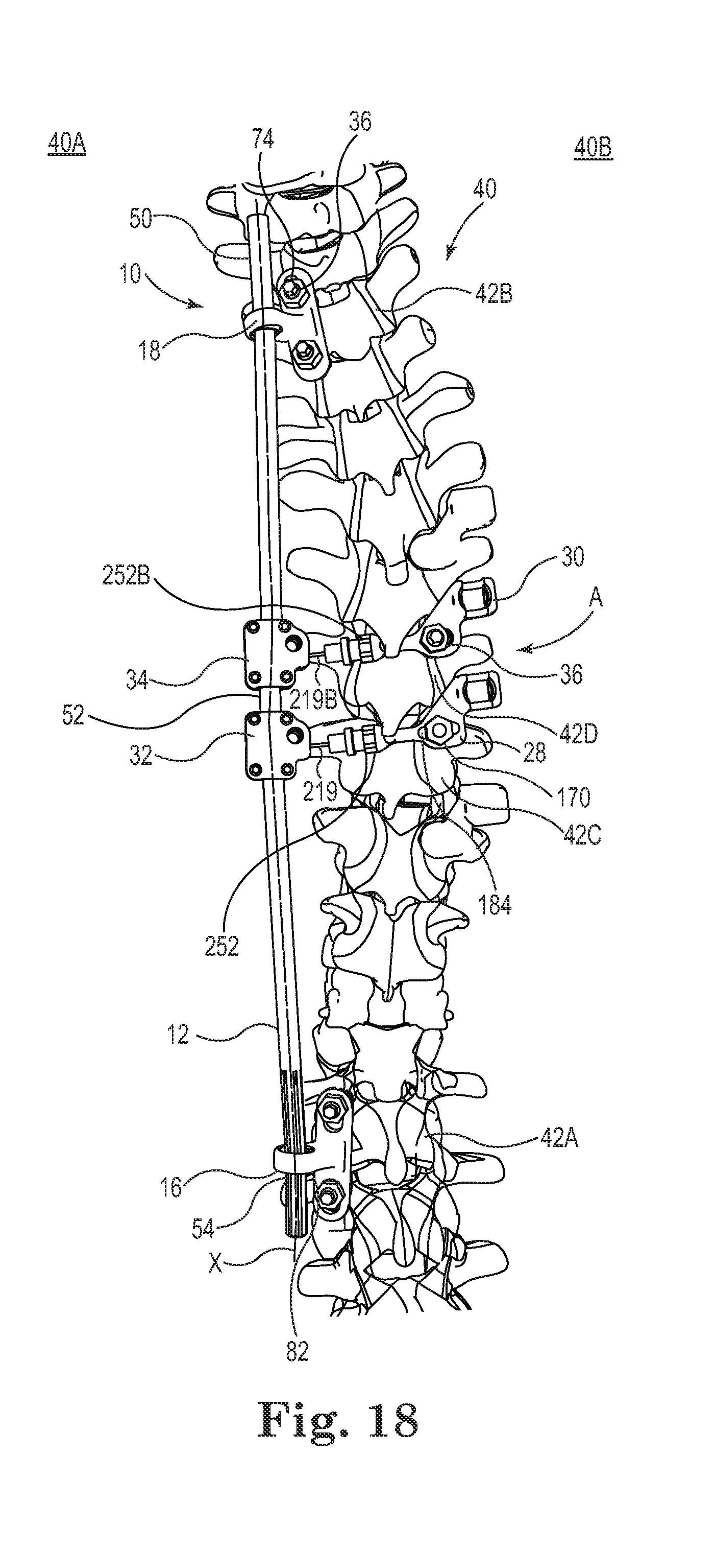
FIG. 18 is an isometric view of the system of FIG. 1 during a correction procedure, according to some embodiments.
FIGS. 19 and 20 are isometric views of the system of FIG. 1 before and after assembly of a second rod into the system, according to some embodiments.
FIGS. 21 to 23 are isometric views of the system of FIG. 1 showing a process of separating and removing portions of the first rod and stabilizing anchors, according to some embodiments.
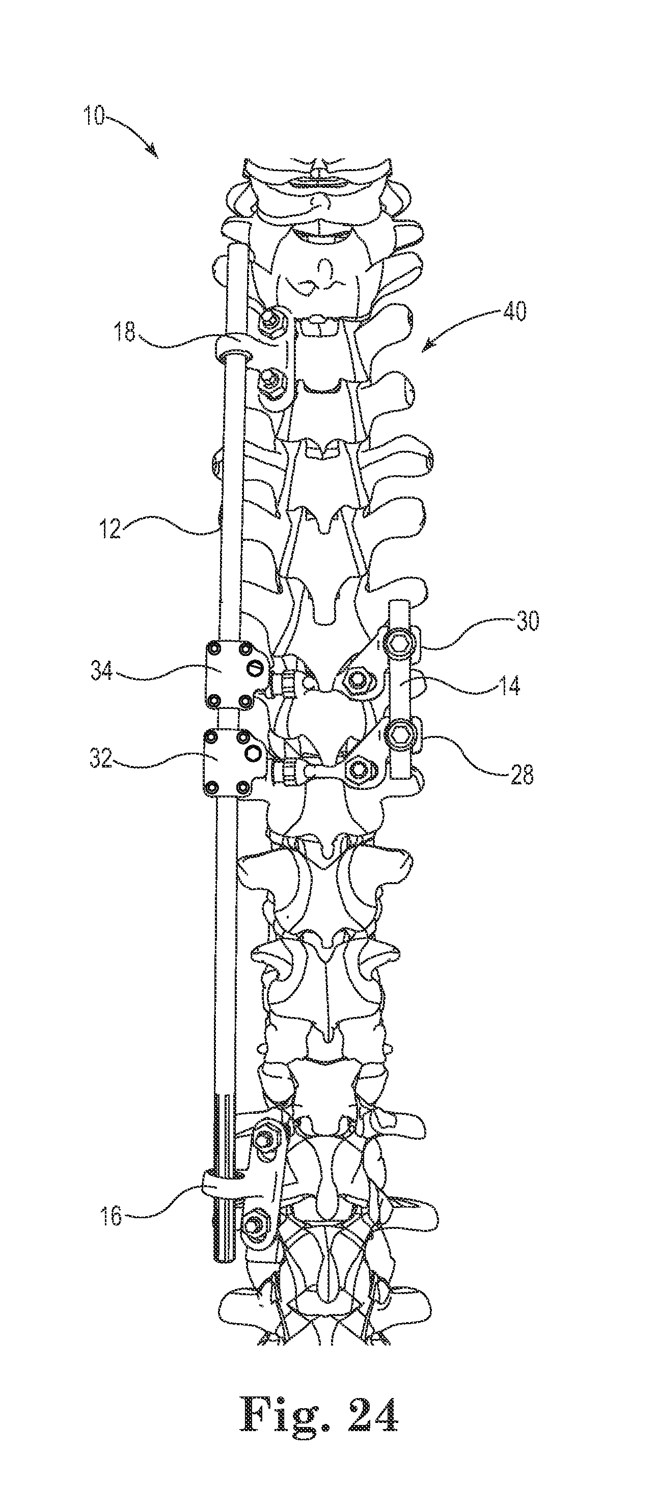
FIG. 24 is an isometric view of a system of another configuration, according to some embodiments.
FIG. 25 is an isometric view of another anchor of an implantable spinal correction and fusion system, according to some embodiments.
FIG. 26 is an isometric view of another anchor of an implantable spinal correction and fusion system, according to some embodiments.
FIG. 27 shows another configuration for an implantable spinal correction and fusion system, according to some embodiments.
FIG. 28 shows another configuration for an implantable spinal correction and fusion system, according to some embodiments.
FIG. 29 shows another configuration for an implantable spinal correction and fusion system, according to some embodiments.
While the invention is amenable to various modifications and alternative forms, specific embodiments have been shown by way of example in the drawings and are described in detail below. The intention, however, is not to limit the invention to the particular embodiments described. On the contrary, the invention is intended to cover all modifications, equivalents, and alternatives falling within the scope of the invention as defined by the appended claims.
DETAILED DESCRIPTION
Some embodiments relate to a spinal correction and fusion system for implantation into a patient, as well as associated methods and devices. In general terms, the system provides for lateral translational corrective force(s) and/or derotational corrective force(s) on a spinal column with associated instrumentation for facilitating vertebral fusion at a selected region of the spine. Some features of the system include implementation of a first, relatively longer rod for initial correction, a second, shorter rod for secondary spinal stabilization. If desired, the secondary stabilization helps promote a fusion process. In some embodiments, the spine retains freedom of motion above and below the spinal segment corresponding to the shorter rod, with the first, relatively longer rod remaining implanted. In other embodiments, the first, relatively longer rod is trimmed and removed following correction of the spinal column and implementation of the second, shorter rod. A variety of additional features and advantages of the inventive systems are contemplated and provided by the instant disclosure.
FIG. 1 shows a spinal correction and fusion system 10, the system 10 including a first rod 12; a second rod 14; a plurality of anchors, including a first stabilizing anchor 16, a second stabilizing anchor 18, a first anchor 20, a second anchor 22, a third anchor 24, a fourth anchor 26; a first transverse anchor 28; a second transverse anchor 30; a first adjustment assembly 32; a second adjustment assembly 34; and a plurality of fasteners 36, such as bone screws, for securing components of the system 10 to a spine, or spinal column 40 having a first side 40A and a second side 40B. The system 10 is optionally used to bring the spine 40 to a more natural curvature (e.g., using a single adjustment). In other embodiments, an abnormal curvature in the spinal column 40 has been adjusted to a more natural curvature using other hardware, prior to or in conjunction with securing portions of the system 10 to the spinal column 40. In some embodiments, the system 10 is adapted to initially provide means for leveraged correction, with translation and derotation of the spine. If desired, the system 10 is adapted to provide means for selective fusion of the spine following correction. In other embodiments, the system 10 provides means for maintaining a correction to facilitate spine remodeling without vertebral fusion, or without permanent vertebral fusion.
Although the system 10 is shown with a select number of components, such as two stabilizing anchors 16, 18 two transverse anchors 28, 30, and two adjustment assemblies 32, 34, more or fewer are implemented as appropriate. For example, in some embodiments a single transverse anchor, such as the first transverse anchor 28, is secured to one or more of a plurality of vertebrae 42 at an apex A of a spinal deformation, with a corresponding adjustment assembly, such as the first adjustment assembly 32, coupled to the transverse anchor 28. Moreover, although four anchors 20, 22, 24, 26 are shown, in some embodiments there are more or less of the anchors. For example, in some embodiments the system 10 includes the first rod 12, the second rod 14, a single transverse anchor, such as the transverse anchor 28 and a single anchor, such as the third anchor 24, with the second rod 14 secured between the transverse anchor 28 and the third anchor 24. In still other embodiments, the system 10 does not include any of the anchors 20, 22, 24, 26, but instead the second rod 14 is secured between the first and second transverse anchors 28, 30 (see, e.g., FIG. 24). A variety of other configurations are also contemplated.
Various planes and associated directions are referenced in the following description, including a sagittal plane defined by two axes, one drawn between a head (superior) and tail (inferior) of the body and one drawn between a back (posterior) and front (anterior) of the body; a coronal plane defined by two axes, one drawn between a center (medial) to side (lateral) of the body and one drawn between a head (superior) and tail (inferior) of the body; and a transverse plane defined by two axes, one drawn between a back and front of the body and one drawing between a center and side of the body. The terms pitch, roll, and yaw are also used, where roll generally refers to angulation, or rotation, in a first plane through which a longitudinal axis of a body orthogonally passes (e.g., rotation about a longitudinal axis corresponding to the spinal column), pitch refers to angulation, or rotation, in a second plane orthogonal to the first plane, and yaw refers to angulation, or rotation, in a third plane orthogonal to the first and second planes. In some embodiments, pitch is angulation in the sagittal plane, yaw is angulation in the coronal plane, and roll is angulation in the transverse plane.
In various embodiments, changes in pitch, yaw, and/or roll occur concurrently or separately as desired. Moreover, as used herein, "lateral translation" is not limited to translation in the medial-lateral direction unless specified as such.
As shown in FIG. 1, in some embodiments the first rod 12, also described as an elongate member, is secured to the spinal column 40 at a pre-selected offset from a longitudinal axis of the spinal column 40. For example, the first rod 12 is optionally secured at an offset along a medial-lateral axis ML, or right-left axis, and anterior-posterior axis AP, or back-front axis. In some embodiments, the first rod 12 is secured on the left side of the spinal column 40 as shown. As subsequently described, the offset is optionally selected to cause at least a relative lateral translation (e.g., central or medial movement) and derotational shift of selected vertebrae 42 of the spinal column 40 (relative anterior-posterior movement of selected vertebrae 42 can also be accomplished) such that the spinal column 40 exhibits a more natural position.
The first rod 12 is elongate and cylindrical including a superior portion 50, an intermediate portion 52, and an inferior portion 54. The first rod 12 is adapted, or otherwise structured, to extend along the spinal column 40. The first rod 12 is optionally contoured to complement a desired spinal curvature (e.g., generally following the curvature of a corrected, or natural spine as shown in FIG. 20). In some embodiments, the first rod 12 is substantially rigid, defining a substantially round cross-section with a mean diameter of about 6 mm and being formed of a suitable biocompatible material, such as titanium alloy ASTM F136, or cobalt chromium alloy ASTM F1537 or any other suitable implantable material. If desired, the first rod 12 incorporates some flex, or springiness while substantially rigidly retaining its shape. The first rod 12 is optionally formed of a variety of materials, including stainless steel or suitable polymeric materials.
The first rod 12 has a longitudinal axis X--where the rod 12 is substantially straight, the longitudinal axis X is substantially straight and, where the rod 12 is substantially curved or angled, the longitudinal axis X is similarly curved or angled. The sections 50, 52, 54 of the first rod 12 are optionally continuously formed or are formed as separate, connected parts as desired. In still other embodiments, expandable rod designs are also contemplated.
FIG. 2 is a cross-sectional view of the first rod 12 in the inferior portion 54 of the first rod 12. As shown, the cross-sectional shape of the first rod 12, including various portions thereof, is not limited to circular cross-sections. For example, the inferior portion 54 optionally includes a plurality of splines 60 for mating with the first stabilizing anchor 16. As shown in FIG. 2, the splines 60 are trapezoidal (e.g., similarly to the teeth of a gear) with rounded bases, although a variety of shapes, such as involute shapes, are contemplated.
As shown in FIG. 1, the second rod 14 is substantially shorter than the first rod 12. For example, the second rod 14 is optionally configured (e.g., having a corresponding length and/or longitudinal contour) to extend along an apical region A of the spine 40 and/or between a desired number of anchors, such as the third and fourth anchors 24, 26. The second rod 14 is optionally formed of similar materials and with similar cross-section(s) to that of the first rod 12, as desired.
FIGS. 3 to 8 show the first stabilizing anchor 16 (also described as a rod anchor) of the system 10, according to some embodiments. As shown in FIG. 1, the first stabilizing anchor 16 is adapted, or otherwise structured, to be mounted, or fixed to one or more of the vertebrae 42, such as a first vertebra 42A (FIG. 1) located at an inferior position, or other position, along the spine 40.
As shown in FIG. 3, the first stabilizing anchor 16 is adapted to receive, and includes means for receiving, the first rod 12 such that the first rod 12 is secured laterally, against lateral translation relative to the first stabilizing anchor 16. In some embodiments, the first rod 12 is substantially prevented from translating in a direction substantially perpendicular to the longitudinal axis X at a first pivot point P1. In turn, the first rod 12 is able to slide axially, or translate axially, along the longitudinal axis X of the first rod 12, relative to the first stabilizing anchor 16 through the first pivot point P1. The rod 12 is also able to change in pitch and yaw about the first pivot point P1. The first stabilizing anchor 16 is adapted, or otherwise structured, to limit rotation, or roll, of the first rod 12 about the longitudinal axis X of the first rod 12. In particular, the first stabilizing anchor 16 provides means for allowing the rod 12 to angulate without substantial lateral translation relative to the first stabilizing anchor 16 and without substantial rotation about the longitudinal axis X.
FIG. 4 is an isometric view of the first stabilizing anchor 16. As shown, the first stabilizing anchor 16 is optionally formed of biocompatible materials and includes a mounting portion 70 and a housing portion 72. The mounting portion 70 is adapted to secure the first stabilizing anchor 16 to one or more vertebrae 42, such as the first vertebra 42A and an additional vertebra 42 above or below the first vertebra 42A. In other embodiments, the mounting portion 70 is secured to a single vertebra, such as the first vertebra 42A (e.g., laterally across the first vertebra 70B at the pedicles, or at a single point--such as a single pedicle--on the first vertebra 26A. In some embodiments, the mounting portion 70, also described as a plate, is adapted to be secured at two or more points, for example spanning between two vertebrae 42 (e.g., the L3-L4 vertebrae) or spanning across a portion of a single vertebra 42 (e.g., pedicle-to-pedicle on a single vertebra).
In some embodiments, the mounting portion 70 includes a pedestal with first and second anchor locations, each of the anchor locations defining a surface suitable for mounting the first stabilizing anchor 16 to one or more vertebrae 42. The first and second anchor locations each optionally include through holes 74 for receiving one of the fasteners 36, such as a pedicle screw or similar device to secure the mounting portion 70 to one or more vertebrae 42, such as the first vertebra 42A.
The housing portion 72 of the first stabilizing anchor 16 includes a body 80 and a sleeve insert 82. In some embodiments, the sleeve insert 82 is substantially spherical in shape and the body 80 forms a substantially spherical mating race for receiving the sleeve insert 82. The body 80 has a sleeve aperture 84 (FIG. 5) extending front-to-back through the body 80, the sleeve aperture 84 defining a revolute, substantially concave articulation surface 86 (FIG. 5). The sleeve insert 82, in turn, forms a complementary revolute, substantially convex articulation surface 88. As shown in FIG. 3, the body 80 also has a pin chase 90 (e.g., a cylindrical through hole) that defines a terminal seat 92 having a larger diameter than a remainder of the pin chase 90.
FIG. 5 is a plan view of the first stabilizing anchor 16, showing the sleeve insert 82 as it would be received within the body 80 (though normally hidden from view). As shown, the concave articulation surface 86 of the aperture 84 defines opposed apices 89 on each side of the articulation surface 86. The articulation surfaces 86, 88 are adapted, or otherwise structured, to form a substantially complementary fit with one another, such that the sleeve insert 82 is able to be captured by the body 80 within the aperture 94 and have relative angular movement with respect to the body 80. To facilitate assembly of the sleeve insert 82 into the body 80, the aperture 84 includes first and second channels 94, 96 formed into the articulation surface 86 at the apices 89 such that the minimum effective internal diameter D of the aperture 84 is increased between the channels 94, 96. The channels 94, 96 extend front to back through the body 80 and are positioned on opposite sides of the body 80. While two channels are shown, in other embodiments a single channel is included. FIG. 8 is a front view of the stabilizing anchor 16. As shown in FIGS. 5 and 8, the channels 94, 96 have arcuate profiles and extend into the aperture 84 to the apices 89 on each side of the articulation surface 86. The profiles of the channels 94, 96 are optionally complementary in shape to a portion of the profile--the lateral edges, or sides--of the sleeve insert 82 such that the sleeve insert 82 is able to be received through the channels 94, 96 into the aperture 84 when the sleeve insert 82 is oriented perpendicular, or edgewise relative to the body 80. The body 80 also includes a protrusion 98 (FIG. 3) (e.g., a pin) or protrusions (not shown) that extends inwardly into the aperture 84 from the articulation surface 86.
As shown in FIG. 3, the sleeve insert 82 has a passage 100 defining the pivot point P1 through which the splined, or inferior portion 54 of the first rod 12 is able to be slidably received. The sleeve insert 82 also has a groove 110 extending parallel to the center line of the sleeve insert into the convex articulation surface 88. The groove 110 is adapted to receive the protrusion 98 for limiting roll of the sleeve insert 82 within the body 80. The pivot point P1 is defined in the passage 100, where upon assembly the first rod 12 passes through the first pivot point P1 such that the longitudinal axis of the rod at the first pivot point P1 is generally concentric with the center of the passage 100.
As shown, the passage 100 has a non-circular cross-section (e.g., a splined cross-section corresponding to the inferior portion 54 of the first rod 12). Upon mating the non-circular cross-sections of the first rod 12 and the passage 100, rotation of the first rod 12 relative to the sleeve insert 82 is substantially inhibited or prevented. In some embodiments, the passage 100 defines a plurality (e.g., six) of inward splines 112 and a plurality of recessed pockets 114 (e.g., six) between the splines 112. The splines 112 are optionally trapezoidal (e.g., like the teeth of a gear) in shape overall. A variety of shapes are contemplated for the splines 112, including involute shapes, for example. The pockets 114 optionally include corner recesses 116 that are rounded in shape (e.g., to help prevent binding between the passage 100 and the first rod 112 during sliding of the first rod 112 in the passage 100). In some embodiments, the splines 60, 112 are designed to help maximize efficiency of torque transfer between the first rod 12 and the sleeve insert 82 while reducing contact pressure angle(s) between the components.
The protrusion 98 is optionally a pin with a head 120, a neck 122, and a body 124, the neck 122 being located between the head 120 and the body 124. The head 120, the neck 122, and the body 124 are optionally substantially cylindrical with the head 120 having a greater diameter than the body 124 and the body 124 having a greater diameter than the neck 122. The protrusion 98 is received in the pin chase 90 with the head 120 received in the seat 92 such that the head projects into the aperture 84. In some embodiments the protrusion 98 is press fit into the pin chase 90 and/or welded, adhered, or otherwise secured within the pin chase 90. In other embodiments the protrusion is temporary and is removable, providing temporary prevention of roll of the sleeve insert 82 within the body 80 so that the first stabilizing anchor 16 is able to be adjusted so that the rod 12 is free to rotate.
FIGS. 6, 7, and 8 show the sleeve insert 82 being assembled into the body 80 by positioning the sleeve insert 82 perpendicular, or edgewise, relative to the aperture 84 (FIG. 5) and sliding the sleeve insert 82 into the channels 94, 96. In other embodiments, the sleeve insert 82 is able to be inserted at another angle (45 degrees, for example). In this position, the diametric plane of the sleeve insert 82 is generally parallel to the centerline Z of the aperture 84. In alternate terms, the centerline W of the sleeve insert 82 is generally parallel to the diametric plane of the aperture 84. Once received in the aperture 84 via the channels 94, 96, the sleeve insert 82 is rotated such that the protrusion 98 (FIG. 3) is received in the groove 110 (e.g., as shown in FIGS. 3, 4, and 5). With the protrusion 98 slidably received in the groove 110, the pitch and yaw of the first rod 12 are still able to change while roll is substantially limited. The first rod 12 also remains free to slide axially within the sleeve insert 82, according to some embodiments.
As relative rotation between the sleeve insert 82 and the body 80 is also substantially inhibited, relative rotation between the first rod 12 and the first stabilizing anchor 16 is substantially inhibited or limited, allowing the first rod 12 to be maintained at a pre-selected rotational position relative to the first stabilizing anchor 16. It also should be understood that other cross-sectional shapes for each of the passage 100 (FIG. 3) and first rod 12 can be selected to allow some degree of rotation about the longitudinal axis X within a predefined range.
In some embodiments, the second stabilizing anchor 18 is substantially similar to the first stabilizing anchor 16, including any desired combination of previously-described features. As shown in FIG. 9, the second stabilizing anchor 18 is substantially similar to the first stabilizing anchor 16, with the exception that the second stabilizing anchor 18 has a smooth bore 130 for receiving the first rod 12. The second stabilizing anchor 18 is adapted to be fixed, and provides means for fixation to a second vertebra, such as a second vertebra 42B (FIG. 1). The second stabilizing anchor 18 is further adapted to receive, and provides means for receiving the first rod 12 (FIG. 1) such that the second stabilizing anchor 18 limits translational movement of the first rod 12 except along the longitudinal axis X (i.e., the second stabilizing anchor 18 allows sliding movement of the first rod 12) and allows the first rod 12 to change in at least pitch and yaw about a second pivot point P2. Moreover, as shown the second stabilizing anchor 18 allows the first rod 12 to change in roll about the second pivot point P2.
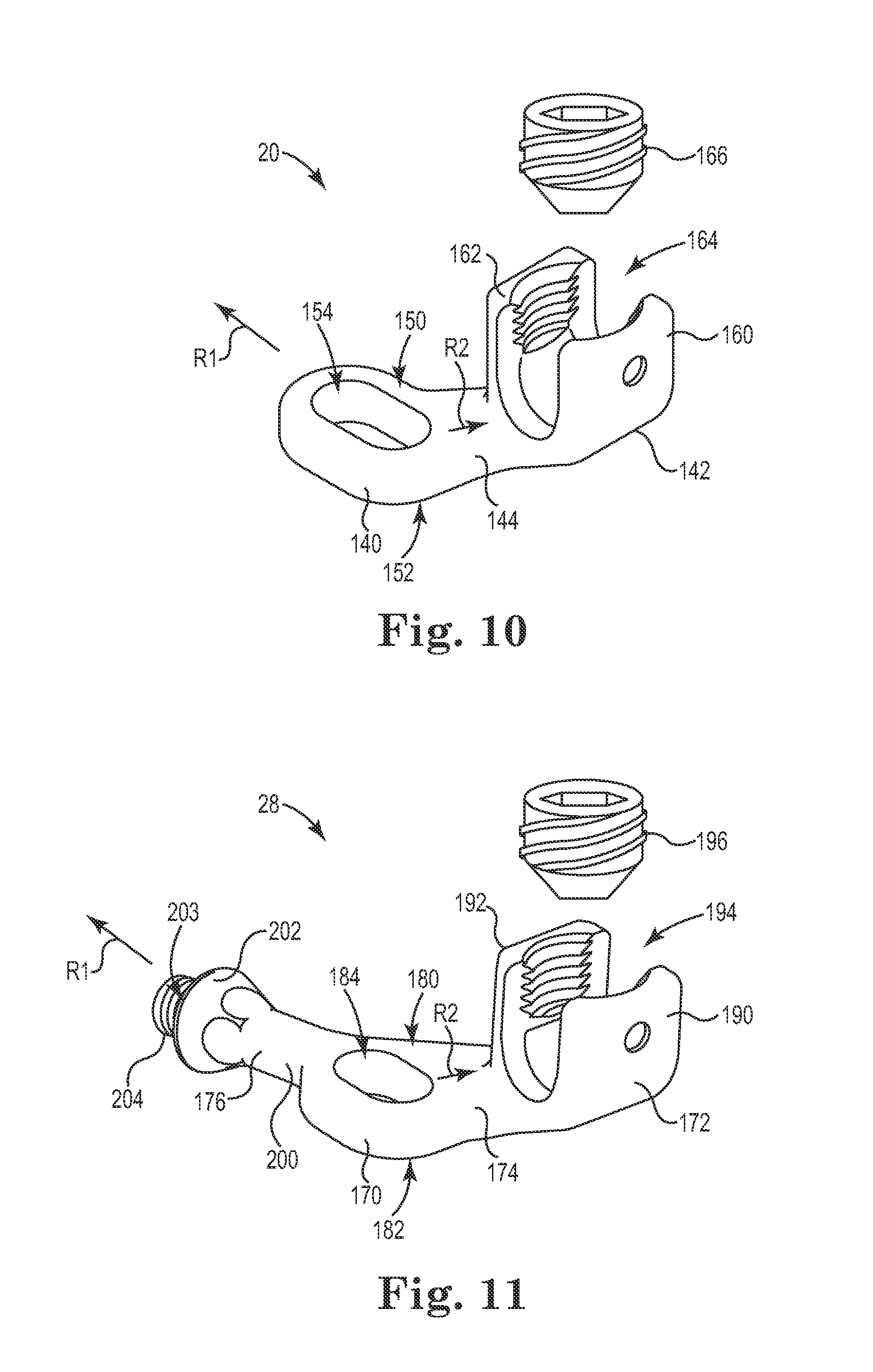
The first anchor 20 is shown in greater detail in FIG. 10, according to some embodiments. The first, second, third, and fourth anchors 20, 22, 24, 26 (FIG. 1) are optionally substantially similar, and thus various features of the anchors are described in association with the first anchor 20, where when referenced, features of the first anchor 20 are designated with reference numbers and similar features of the second, third, and fourth anchors 22, 24, 26 are designated with the same reference numbers followed by a "B," "C," and "D," respectively.
As shown, the first anchor 20 includes a mounting portion 140, a head portion 142, and a connection portion 144. The mounting portion 140 has a top surface 150, a bottom surface 152, and a slot 154 for receiving one of the fasteners 36, such as a pedicle screw or other bone screw. The slot 154, also described as an aperture, is elongate and extends longitudinally in a first direction R1.
The head portion 142 is substantially U-shaped, including a first prong 160 and a second prong 162 defining a pocket 164 for receiving one of the first and second rods 12, 14. As shown, the prongs 160, 162 are threaded for receiving a clamping screw 166 adapted to engage and secure one of the first and second rods 12, 14 immobilized within the pocket 164.
The connection portion 144 extends in a second direction R2 that is offset from the first direct R1. The connection portion 144 extends between the mounting portion 140 and the head portion 142 at an angle of about 45 degrees, for example, relative to the first direction R1.
The first and second transverse anchors 28, 30 are optionally substantially similar, and thus various features of both the first and second transverse anchors are described in association with the first transverse anchor 28, where when referenced, features of the first transverse anchor 28 are designated with reference numbers and similar features of the second transverse anchor 30 are designated with the same reference numbers followed by a "B."
The first transverse anchor 28 is shown in greater detail in FIG. 11, according to some embodiments. As shown, the first transverse anchor 28 includes a mounting portion 170, a head portion 172, a connection portion 174, and an arm portion 176. The mounting portion 170 has a top surface 180, a bottom surface 182, and a slot 184 for receiving one of the fasteners 36, such as a pedicle screw. The slot 184 is elongate and extends longitudinally in a first direction R1. In some embodiments, the arm portion 176 generally extends away from the mounting portion 170 for purpose of coupling to the first rod 12 and the head portion serves to couple the first transverse anchor 28 to the second rod 14.
The head portion 172 is substantially U-shaped, including a first prong 190 and a second prong 192 defining a pocket 194 for receiving the second rod 14. As shown, the prongs 190, 192 are threaded for receiving a clamping screw 196 adapted to engage and secure the second rod 14 immobilized within the pocket 194.
The connection portion 174 extends in a second direction R2 that is offset from the first direct R1. The connection portion 174 extends between the mounting portion 170 and the head portion 172 at an angle of about 45 degrees, for example, relative to the first direction R1. In other embodiments, the connection portion 174 extends between the mounting portion and head portion 170, 172 at another angle, such as from about 30 to about 60 degrees, or at no angle (i.e., the portions 170, 172, 174 are generally in-line with one another).
The arm portion 176 includes a neck section 200 that is substantially elongate and cylindrical, a shoulder section 202 that is flared and defines an abutment face 203, and a terminal section 204 that is threaded. The arm portion 176 extends longitudinally in the first direction R1. The arm portion 176 is adapted to extend across a portion of one of the vertebrae 42 for example, from one side of the spinal column 40 to an opposite side of the spinal column 40. For example, the first transverse anchor 28 is secured to one of the vertebrae 42 such that the arm portion 176 extends laterally across the vertebra 42.
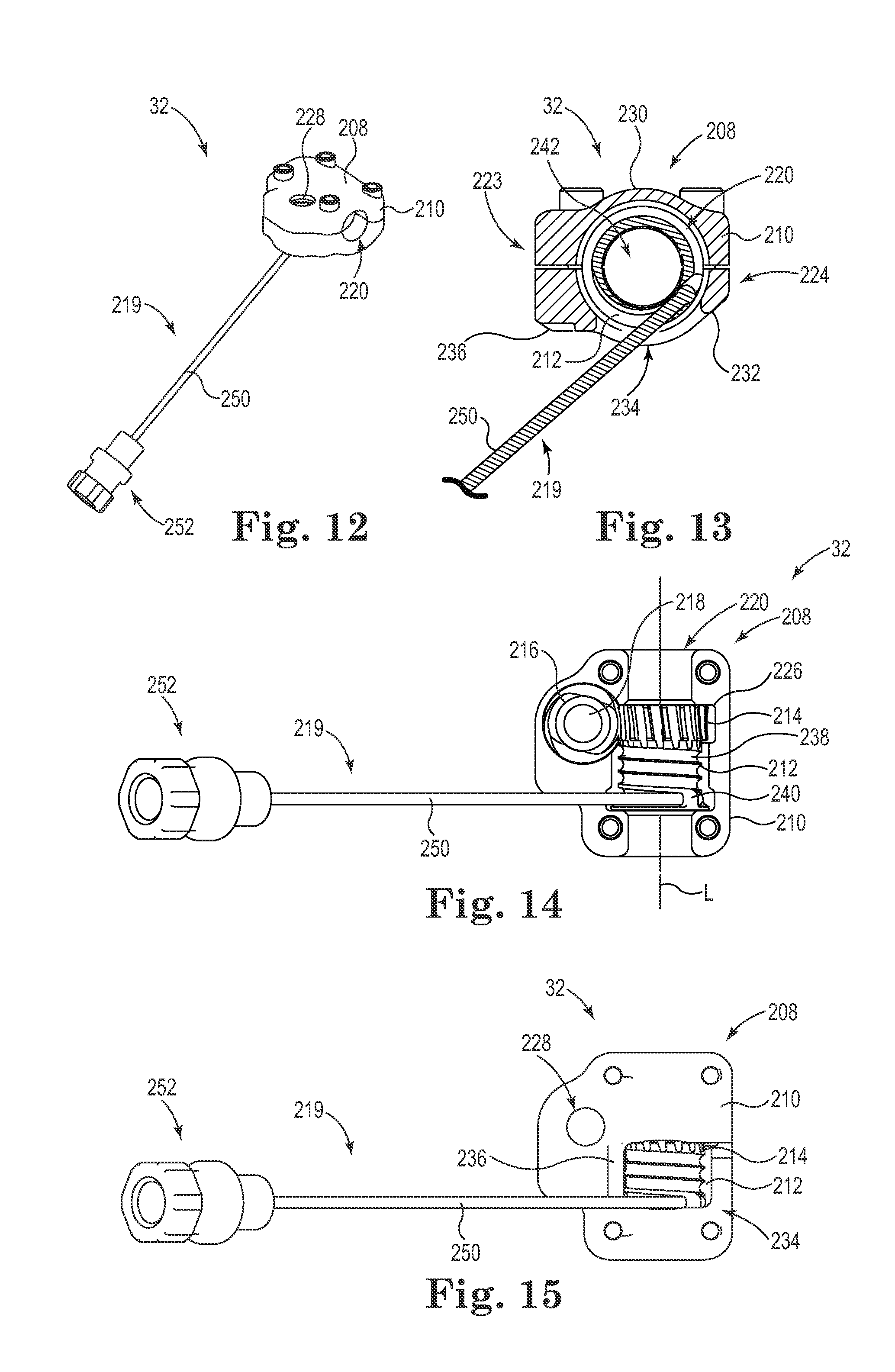
FIG. 12 shows the first adjustment assembly 32 from an isometric view, FIG. 13 shows the adjustment 32 assembly from a cross-sectional view, FIG. 14 shows the adjustment assembly 32 from a plan view with a portion of the housing removed, and FIG. 15 shows the adjustment assembly 32 from a plan view with the housing intact, according to some embodiments.
The first adjustment assembly 32 is adapted to adjust, and provides means for adjusting tension and/or a distance between the first rod 12 and the first transverse anchor 28. The first and second adjustment assemblies 32, 34 are optionally substantially similar. Thus, various features of both the first and second adjustment assemblies 32, 34 are described in association with the first adjustment assembly 32, where features of the first adjustment assembly 32 are designated with reference numbers and similar features of the second adjustment assembly 34 are designated with the same reference numbers followed by a "B."
As shown, the first adjustment assembly 32 includes a tensioner 208, the tensioner 208 including a housing 210, a reel 212, a circumferential gear 214 surrounding the reel 212, a drive gear 216 in contact with the circumferential gear 214, and an actuation head 218. The first adjustment assembly 32 also includes an elongate connector 219 adapted to be wound about the reel 212.
The reel 212, as well as the circumferential gear 214 and drive gear 216 are maintained at least partially within the housing 210. In turn, the housing 210 is adapted to be secured to the first rod 12. For example, the housing 210 optionally forms a central lumen 220 through which the rod first 12 is receivable. Upon inserting the first rod 12 through the central lumen 220, the housing 210 is adapted to be clamped onto the first rod 12.
In some embodiments, the housing 210 defines a first side 223 and a second side 224 and incorporates a clamshell design (e.g., a first portion adjustably secured to a second portion) adapted to be tightened onto the first rod 12 (e.g., using one or more fasteners). Thus, in some embodiments, the first adjustment assembly 32 is substantially fixed with respect to the first rod 12. Other designs, such as monolithic housing designs and others are contemplated. Moreover, in some embodiments, the first adjustment assembly 32 is movable with respect to the first rod 12, for example being able to slide and/or rotate about the first rod 12.
The central lumen 220 of the housing 210 defines a longitudinal axis L and forms a pocket 226 for receiving the reel 212 and the circumferential gear 214 such that the reel 212 and the circumferential gear 214 are able to rotate within the housing 210. The housing 210 also defines a pair of opposed apertures 228 for receiving ends of the drive gear 216 to retain the drive gear 216 while allowing the drive gear 216 to rotate. As shown, the housing 210 also defines a top 230 and a bottom 232, where the bottom 232 forms a lower opening 234 and a raised abutment 236 adjacent to the lower opening 234, toward the first side 223 of the housing 210.
As shown, the reel 212 includes a helical groove 238 for receiving the elongate connector 219 and a raised anchor block 240 for securing the elongate connector 219 to the reel 212. For example, the anchor block 240 optionally includes an aperture for receiving the elongate connector 219 and is welded or otherwise fastened in the aperture. The reel 212, as well as the circumferential gear 214, form a lumen 242 for coaxially receiving the first rod 12. In some embodiments, by receiving the first rod 12 through the reel 212 and circumferential gear 214, an overall size, or profile, of the tensioner 208 is able to be reduced.
As shown, the circumferential gear 214 is connected to, and coaxially aligned with the reel 212. The circumferential gear 214 is engaged with the drive gear 216 such that rotation of the drive gear 216 causes the circumferential gear 214, and thus, the reel 212, to turn (e.g., in a worm or crossed-spur gear configuration).
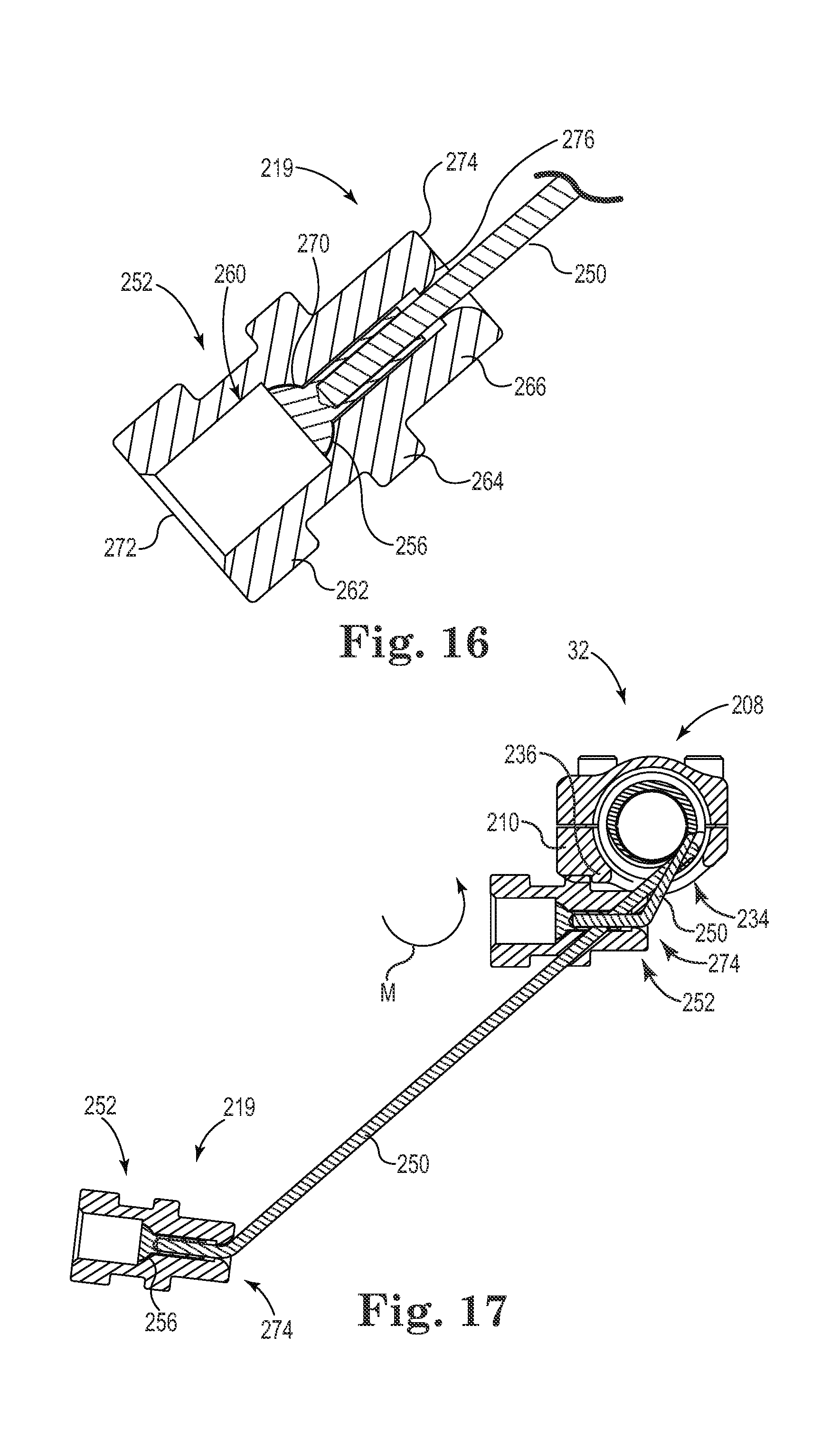
The elongate connector 219 includes a flexible tether 250 and a connector head 252. In some embodiments, the flexible tether 250 is substantially flexible and able to be pivoted in a multiple directions and/or be spooled or wound, for example. Suitable flexible materials include wire and stranded cables, monofilament polymer materials, multifilament polymer materials, multifilament carbon or ceramic fibers, and others. In some embodiments, the flexible tether 250 is formed of cobalt chromium alloy or titanium alloy wire or cable, although a variety of materials are contemplated. The flexible tether 250 includes a terminal cap 256 (FIG. 16) adapted to be secured in the connector head 252. The terminal cap 256 has a rounded (e.g., semi-circular) head and is optionally swaged onto the flexible tether 250. In other embodiments, rather than a swage a loop or other feature is implemented to connect of the connector head 252.
FIG. 16 is a cross-sectional view of the connector head 252, according to some embodiments. As shown, the connector head 252 defines an internal bore 260 and forms a collar 262, a raised shoulder 264, and a neck 266. The internal bore 260 has a rounded seat 270 (e.g., a substantially concave seat). The connector head 252 also has a first end 272 and a second end 274, the second end 274 having a rounded inner profile 276 (like the horn of a trumpet). The flexible tether 250 is secured to the connector head 252 by receiving the terminal cap 256 in the rounded seat 270 in a complementary fit.
The elongate connector 219, also described as a connector or cable, is adapted to be secured to the first transverse anchor 28 and the first adjustment assembly 32. So secured, the elongate connector 219 defines an effective length between the first transverse anchor 28 and tensioner 208 and, and thus the first rod 12 (although, in some embodiments, the elongate connector 219 is secured directly to the rod 12). As described, in some embodiments, the tensioner 208 is adapted to modify, and provides means for modifying, the effective length of the tether 250 of the elongate connector 219 (e.g., by spooling the tether 250 on and off of the reel 212).
The elongate connector 219 is attached or secured to the reel 212 and passes out of the housing 210 through the lower opening 234 in the housing 210. Although a lower opening is shown, in other embodiments the opening is in the side or top, for example. Actuation of the drive gear 216 via the actuation head 218 turns the circumferential gear 214, which turns the reel 212, thus winding (or unwinding, depending on the direction in which the reel 212 is turned) the elongate connector 219 about the reel 212. Rotation of the reel 212 in the appropriate direction draws the tether 250 in toward the tensioner 208 (FIG. 17), pulling the first transverse anchor 28 toward the tensioner 208, according to some methods of correcting a spinal defect.
FIG. 17 shows the first actuation assembly 32 as it would appear in a first, extended state attached to the uncorrected spinal column 40 (e.g., FIG. 18) and as it would appear in a second, retracted state as attached to the corrected spinal column (e.g., FIG. 19), according to some embodiments. As shown, the connector head 252 engages the raised abutment 236 and the housing 210 as the tether 250 is drawn into the housing 210. This engagement and/or the orientation of the lower opening 234 (i.e., with the tether 250 exiting the housing 210 through the bottom) helps generate a moment M on the first transverse anchor 28 (not shown in FIG. 17) thereby helping to derotate the third vertebra 42C to which the first transverse anchor 28 is attached. The ability of the tether 250 to flex and bend at the second end 274 of the connector head 252 helps generate a polyaxial connection at the second end 274 and facilitates generation of the moment M as described.
FIG. 18 shows the assembled system 10. In some embodiments, assembly of the system 10 and associated methods of correcting the spine 40 include securing the stabilizing anchors 16, 18 to inferior and superior portions of the spine 40. For example, the first stabilizing anchor 16 is optionally secured to the spine 40 by driving one of the plurality of fasteners 36 through each of the through holes 74 and into one or more of the vertebrae 42. For example, as shown in FIG. 1, the first stabilizing anchor 16 is secured with one of the fasteners 36 driven into a pedicle of the first vertebra 42A and another of the fasteners 26 driven into a pedicle of another vertebra that is adjacent to the first vertebra 42A. The second stabilizing anchor 18 is similarly secured to the second vertebra 42B and a vertebra adjacent the second vertebra 42B. As shown, each of the first and second stabilizing anchors is secured on the first side 40A of the spine.
The first and second actuation assemblies 32, 34 are slid onto or otherwise coupled to the first rod 12 and then secured (e.g., clamped) at a desired location along the rod 12. The first rod 12 is received in the first and second stabilizing anchors 16, 18, with the splined, or inferior portion 54 of the first rod 12 slidably received in the sleeve insert 82 of the first stabilizing anchor 16 and the superior portion 50 of the rod 12 slidably received in the second stabilizing anchor 18. Thus, in some embodiments the first rod 12 extends along the first side 40A of the spine 40 and is secured against lateral movement relative to a portion of the spine 40.
In some embodiments, the first rod 12 is attached by the stabilizing anchors 16, 18 to pedicles and/or transverse processes on the first side 40A of the spinal column 40 and is able to slide axially relative to the first and/or second stabilizing anchors 16, 18. In other embodiments, the rod 12 is attached by the stabilizing anchors 16, 18 to the second side 40B of the spinal column 40, on different sides of the spinal column 40 (e.g., the first stabilizing anchor 16 on the left side and the second stabilizing anchor 18 on the right side), or along the mid-line of the spinal column 40. In other embodiments, the first rod 12 is adjustable length to compensate for changes in length of the spinal column 40.
By limiting rotation, or roll, of the first rod 12 relative to the first stabilizing anchor 16, the bend in the first rod 12 is oriented and maintained in a desired rotational position. Maintaining the rotational orientation at one end (i.e., at the first stabilizing anchor 16) is useful, for example, to help ensure that the bend or shape of the rod 12 consistently follows or otherwise appropriately tracks a desired curvature of a spinal column 40. Freedom of rotation at the other end of the first rod 12 (i.e., at the second stabilizing anchor 18), however, still permits the spinal column 40 to have more natural movement while the corrective forces are being applied.
Though not shown, the system 10 optionally includes one or more stop features for limiting axial sliding, or translation of the first rod 12 relative to one of the stabilizing anchors to a desired range. Generally, sliding of the first rod 12 in a particular axial direction is substantially limited, or arrested, when a stop feature engages, or abuts an adjacent stabilizing anchor 16, though other stop mechanisms are contemplated.
The first and second transverse anchors 28, 30 are secured to one or more of the vertebrae 42, such as a third vertebra 42C in an apical region A of the spine 40 and a fourth vertebra 42D in an apical region A of the spine 40. The first transverse anchor 28 is secured to the third vertebra 42C by driving one of the fasteners 36 through the slot 184 in the mounting portion 170 of the first transverse anchor 28. For example, the first transverse anchor 28 is optionally secured into a pedicle and/or transverse processes of the third vertebra 42C on the second side 40B of the spine 40. The second transverse anchor 30 is optionally similarly secured on the second side of the spine 42B to a pedicle of the fourth vertebra 42D. As shown, the arm portions 176, 176B (FIG. 11) of the first and second transverse anchors 28, 30 extend from the second side 40B of the spine 40 to the first side 40A of the spine 40.
The first and second actuation assemblies 32, 34 are secured to the first and second transverse anchors 28, 30 by attaching (e.g., screwing) the connector heads 252, 252B of the elongate connectors 219, 219B to the threaded terminal sections of the transverse anchors 28, 30. Some methods include adjusting a curvature of the spine 40 to a desired curvature using the actuation assemblies 32, 34. For example, the tensioners 208, 208B of the first and second actuation assemblies 32, 34 are actuated (independently or simultaneously) in order to draw the elongate connectors 219, 219B into the respective tensioners 208, 208B, thereby drawing the third and fourth vertebrae 42C, 42D and surrounding portions of the spine 40 toward the first rod 12 and to a more desirable spinal curvature.
As shown in FIG. 19, the first and third anchors 20, 24 are secured to a fifth vertebra 42E and the second and fourth anchors 22, 26 are secured to a sixth vertebrae 42E, 42F of the spine 40, thought each of the connectors is optionally secured to a different vertebra. The first anchor 20 is secured along the spine 40 at a location between the first stabilizing anchor 16 and the first actuation assembly 32 and the second stabilizing anchor 18 is secured at a location between the second stabilizing anchor 18 and the second actuation assembly 34. The first and second anchors 20, 22 are secured on the first side 40A of the spine 40 whereas the third and fourth anchors 24, 26 are secured on the second side 40B of the spine 40 opposite the first and second anchors 20, 22, for example. The first anchor 20 is secured to a pedicle of the fifth vertebra 42E by driving one of the fasteners 36 into the pedicle through the slot 154 in the mounting portion 140 of the first anchor 20 (FIG. The second, third, and fourth anchors 22, 24, 26 are optionally similarly secured to the spine 40.
If desired, the first rod 12 is received in the first and second anchors 20, 22 (e.g., prior to securing the first and second anchors 20, 22 to the spine 40) and the first rod 12 is secured in the pocket 164 of the first anchor 20 using the clamping screw 166 (FIG. 10). The first rod 12 is similarly secured in the second anchor 22, thereby immobilizing the first rod 12 between the first and second anchors 20, 22.
As shown in FIG. 20, the second rod 14 is received in the transverse anchors 28, 30, and optionally in the third and fourth anchors 24, 26 (e.g., prior to securing the third and fourth anchors 24, 26 to the spine 40) in order to provide secondary stabilization to the corresponding region of the spine 40. For example, the second rod 12 is secured in the pocket of the third anchor 24 using the clamping screw and in the pocket 194 of the first transverse anchor 28 using the clamping screw 196 (FIG. 11). The second rod 14 is similarly secured in the second transverse anchor 30 and the fourth anchor 26, thereby immobilizing the second rod 14 between the third and fourth anchors 24, 26. As shown, the first and second rods 12, 14 are on opposite sides of the spine 40, immobilizing a desired region of the spine 40 (e.g., as part of a spinal fusion process), such as an apical region A of the spine 40. As appropriate, bone cement, fillers, or other materials are optionally employed with one or more vertebrae 42 to facilitate intervertebral fusion. In other embodiments, the system 10 is configured to avoid fusion of the spine 40. For example, the first and/or second rods 12, 14 are optionally substantially flexible such that the system 10 allows sufficient movement of the spine 40 to help avoid intervertebral fusion while still providing structural support during growth and remodeling of the spine 40.
As shown in FIG. 21, if desired (e.g., once the spine 40 is stabilized), the first rod 12 is clipped, cut, broken, or otherwise portioned between the first anchor 20 and the first stabilizing anchor 16 and between the second anchor 22 and the second stabilizing anchor 18. As shown in FIG. 22, the superior and inferior portions of the first rod 12 are optionally removed from the first and second stabilizing anchors 16, 18 and the first and second stabilizing anchors 16, 18 are removed from the spine 40. As another alternative, the first rod 12 is not portioned and is left free to move in the stabilizing anchors 16, 18, for example. Moreover, if desired, the entire system 10 is optionally removed after a desired amount of fusion of the spine has been achieved and/or after sufficient growth and remodeling of the spinal curvature has been achieved. For example, once a diseased area of the spine has sufficiently healed (e.g., after being fused and stabilized) the stability provided by the system 10 may no longer be required.
Thus, according to various embodiments, the spinal column 40 (and thus, the person) is able to twist, bend side-to-side, and bend forward-and-backward in a more natural manner while corrective forces are being applied to the spinal column 40 and/or to achieve a desired correction of the spine 40. In some embodiments, the effective lengths of the actuation assemblies 34, 36, and specifically the elongate connectors 219, 219B are adjusted (e.g., periodically or all at one time), bringing the spinal column into natural alignment, while the system 10 facilitates a more natural movement of the spinal column 40 (e.g., twisting and bending forward-and-backward and side-to-side) due to the freedom of movement afforded by the system 10. During a secondary fusion procedure, the second rod 14 is secured to the corrected spine 40 opposite first rod 12 to rigidly secure a region of the spine for fusion as shown in FIG. 23. If desired, this includes immobilizing an apical region A of the spine 40 and leaving a superior region of the spine 40 adjacent to the apical region A and an inferior region of the spine 40 adjacent to the apical region A free to move in at least one degree of freedom. The at least one degree of freedom optionally includes elongation, or growth, compression, twisting, and/or flexing. In some embodiments, the freedom of movement of the first rod 12 provided by the stabilizing anchors 16, 18 helps facilitate this motion. In other embodiments, removal of one or more portions of the system 10 (e.g., clipping and removing portions of the rod 12) facilitates this motion.
In some embodiments, by linking the convex and concave sides of the spine 40 together, stress on the spine 40 is distributed at the anchor-vertebral interfaces as well as stiffening the apical region A of the spine, helping to stabilize the deformity. Thus, in addition to the connection between the apical region A and the first rod 12, the lateral connection between the rods 12, 14 optionally helps resist vertebral rotation and lateral translation).
As previously indicated, in some embodiments, the spine 40 is optionally corrected, or tensioned toward the first rod 12 prior to securing the second rod 14 to the spine 40. In other embodiments, the corrective method includes securing the second rod 14 to the spine 40 (e.g., to partially or fully correct spinal curvature the apical region A) and then tensioning the second rod 14 toward the first rod 12 in order to correct the spine 40 or portions thereof (e.g., a curvature of the spine 40 superior and/or inferior to the apical region A).
As previously indicated, the system 10 may include greater or fewer components according to various embodiments. FIG. 24 is an example of the system 10, which includes correction and secondary stabilization features, the system 10 including fewer components. With reference to FIG. 18, the system 10 is optionally used to correct a spinal deformity (including a total or partial correction) and then the second rod 14 is received in, and secured in, the pockets 194, 194B of the first and second transverse anchors 28, 30. The secondary stabilization provided by the second rod 14 is optionally used to facilitate fusion of the spine 40, including use of growth promoters or other materials for encouraging intervertebral fusion.
FIG. 25 shows another stabilizing anchor 16A (also described as a rod anchor) of the system 10, according to some embodiments. The first stabilizing anchor 16A is adapted, or otherwise structured, to be mounted, or fixed to one or more of the vertebrae 42, such as a first vertebra 42A (FIG. 1) located at an inferior position, or other position, along the spine 40.
As shown, the first stabilizing anchor 16A is substantially similar to the first stabilizing anchor 16. The first stabilizing anchor 16A includes a mounting portion 70A and a housing portion 72A. The mounting portion 70A optionally includes through holes 74A for receiving one of the fasteners 36, such as a pedicle screw or similar device to secure the mounting portion 70A to one or more vertebrae 42, such as the first vertebra 42A.
The housing portion 72A of the first stabilizing anchor 16A includes a body 80A and a sleeve insert 82A. The body 80A is substantially similar to the body 80 of the first stabilizing anchor 16 with an optional difference being that the body 80A is split by a gap 298A dividing the body 80A into a lower portion 300A and an upper portion 302A that can be clamped together with adjustment member 304A (e.g., a bolt) secured across the gap 298A. The sleeve insert 82A, in turn, is substantially similar to the sleeve insert 82 with the addition of a gap 306A that facilitates clamping of the sleeve insert 82A onto the rod 12. For example, upon sufficiently tightening the adjustment member 304A, the sleeve insert 82A is clamped onto rod 12 to arrest sliding and rolling motion of the rod 12 through the sleeve insert 82A. Additionally, the clamping action of the body 80A on the sleeve 82A arrests changes in pitch and yaw. In different terms, the rod 12 is able to be selectively locked relative to the stabilizing anchor 16A.
FIG. 26 shows another stabilizing anchor 16B (also described as a rod anchor) of the system 10, according to some embodiments. The first stabilizing anchor 16B is adapted, or otherwise structured, to be mounted, or fixed to one or more of the vertebrae 42, such as a first vertebra 42A (FIG. 1) located at an inferior position, or other position, along the spine 40.
As shown, the first stabilizing anchor 16B is substantially similar to the first stabilizing anchors 16, 16A and includes a clamping mechanism similar to first stabilizing anchor 16A. The first stabilizing anchor 16B includes a mounting portion 70B and a housing portion 72B. The mounting portion 70B differs from the mounting portion 70A of the first stabilizing anchor 16A in that the mounting 70B portion includes a single through hole 74A for receiving one of the fasteners 36, such as a pedicle screw or similar device to secure the mounting portion 70B to one or more vertebrae 42, such as the first vertebra 42A. In some embodiments, the first stabilizing anchor 16B is adapted to be secured to a single vertebra, as compared to being secured across multiple vertebrae.
FIG. 27 shows the system 10 employing the first stabilizing anchor 16A and a second stabilizing anchor 18A that is substantially the same as the first stabilizing anchor 16A, according to some embodiments. As shown in FIG. 27, the rod 12 of the system 10 is able to slide and change in pitch, yaw, and roll at both of the anchors 16A, 18A and is also able to be selectively locked against sliding, pitch, yaw, and roll at each of the first and second stabilizing anchors 16A, 18A. Selective locking at one or both anchors 16A, 18A is optionally employed for a variety of reasons, including for performing partial or total fusion, to facilitate a correction, or adjustment process using the tensioners 32, 34, or to facilitate assembly of the system 10 prior to a correction operation.
FIG. 28 shows the system 10 employing the first and second stabilizing anchors 16A, 18A similarly to FIG. 27, according to some embodiments. In addition, the first anchor 20 and the second anchor 22 shown in FIG. 27 are replaced by first and second anchors 20B, 22B, which are each substantially the same as the first stabilizing anchor 16B (FIG. 26). As shown in FIG. 28, the rod 12 of the system 10 is able to slide and change pitch, yaw and roll at the anchors 16A, 18A, 20B, 22B and is also able to be selectively locked against sliding, pitch, yaw, and roll at each of the anchors 16A, 18A, 20B, 22B as desired. Once again, selective locking at any of the anchors 16A, 18A, 20B, 22B is optionally employed for a variety of reasons, including for performing partial or total fusion, to facilitate a correction, or adjustment process using the tensioners 32, 34, or to facilitate assembly of the system 10 prior to a correction operation.
FIG. 29 shows the system 10 employing a plurality of anchors, each of which is substantially similar to the first stabilizing anchor 16B (FIG. 26). As shown in FIG. 29, the rod 12 of the system 10 is able to slide and change in pitch, yaw and roll at the anchors 16B, 18B, 20B, 22B. The first anchor 16B optionally employs a chase feature similar to those previously described to limit roll. Alternatively, the first anchor 16B freely permits roll of the rod 12. As shown in FIG. 29, the rod 12 has a high degree of freedom, while being laterally constrained, as desired. In particular, the rod 12 is also able to be selectively locked against sliding, pitch, yaw, and roll at each of the anchors 16B, 18B, 20B, 22B as desired. Once again, selective locking at any of the anchors is optionally employed for a variety of reasons, including for performing partial or total fusion, to facilitate a correction, or adjustment process using the tensioners 32, 34, or to facilitate assembly of the system 10 prior to a correction operation. From the foregoing, it should be understood that a variety of numbers and configurations of the anchors is contemplated. Though not specifically shown, it should also be understood that any of the foregoing anchors are employed with the second rod 14 on the second side of the spine.
Various modifications and additions can be made to the exemplary embodiments discussed without departing from the scope of the present invention. For example, while the embodiments described above refer to particular features, the scope of this invention also includes embodiments having different combinations of features and embodiments that do not include all of the described features. Accordingly, the scope of the present invention is intended to embrace all such alternatives, modifications, and variations as fall within the scope of the claims, together with all equivalents thereof.
* * * * *
D00000
D00001
D00002
D00003
D00004
D00005
D00006
D00007
D00008
D00009
D00010
D00011
D00012
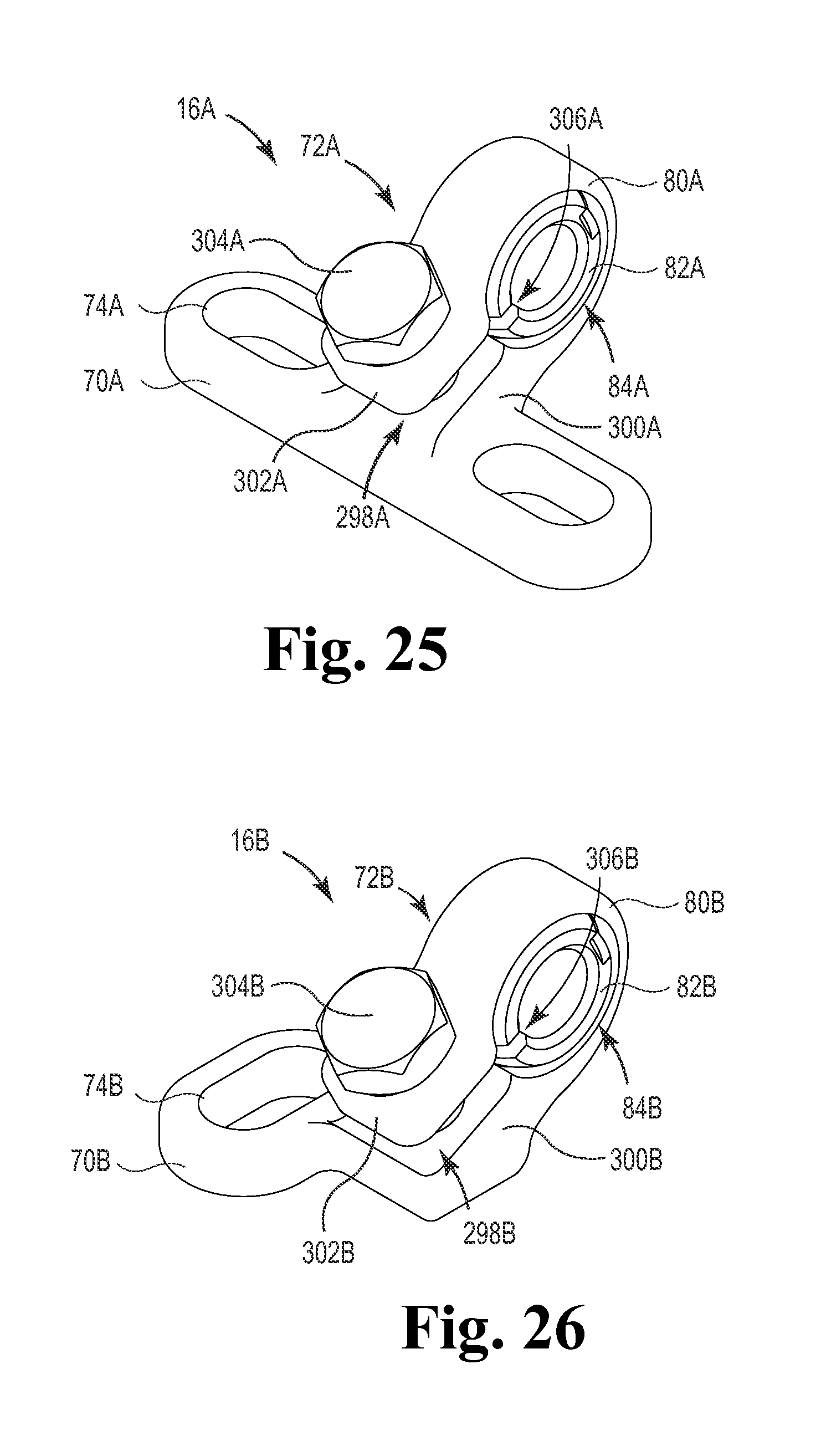
D00013
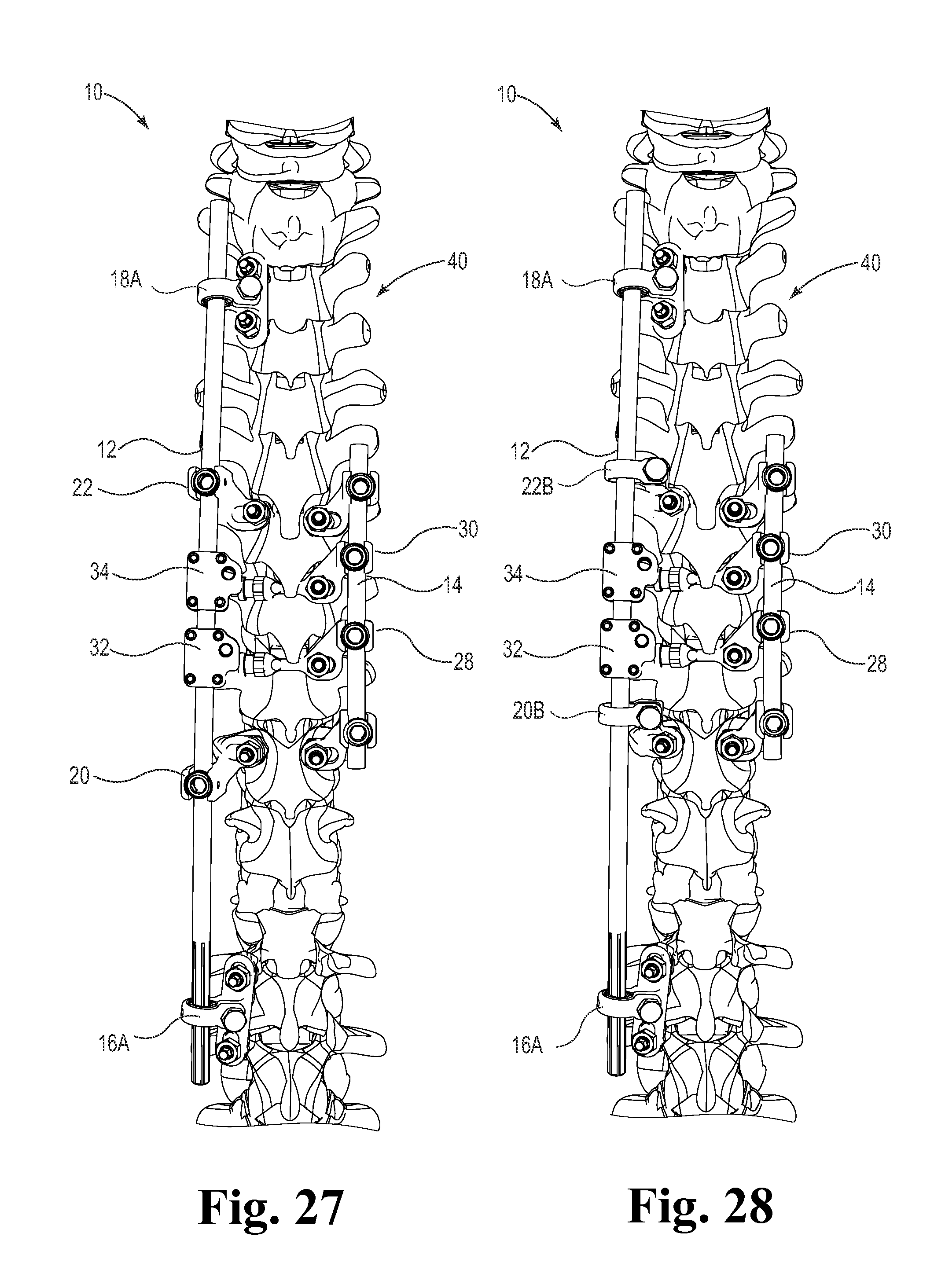
D00014

XML
uspto.report is an independent third-party trademark research tool that is not affiliated, endorsed, or sponsored by the United States Patent and Trademark Office (USPTO) or any other governmental organization. The information provided by uspto.report is based on publicly available data at the time of writing and is intended for informational purposes only.
While we strive to provide accurate and up-to-date information, we do not guarantee the accuracy, completeness, reliability, or suitability of the information displayed on this site. The use of this site is at your own risk. Any reliance you place on such information is therefore strictly at your own risk.
All official trademark data, including owner information, should be verified by visiting the official USPTO website at www.uspto.gov. This site is not intended to replace professional legal advice and should not be used as a substitute for consulting with a legal professional who is knowledgeable about trademark law.