Split type aerostatic bearing
Li , et al. December 30, 2
U.S. patent number 8,920,031 [Application Number 14/002,561] was granted by the patent office on 2014-12-30 for split type aerostatic bearing. This patent grant is currently assigned to Shanghai Micro Electronics Equipment Co., Ltd.. The grantee listed for this patent is Jie Fang, Jinchun Li, Liwei Wu, Hai Xia, Yeqin Zheng. Invention is credited to Jie Fang, Jinchun Li, Liwei Wu, Hai Xia, Yeqin Zheng.

| United States Patent | 8,920,031 |
| Li , et al. | December 30, 2014 |
Split type aerostatic bearing
Abstract
A split-type aerostatic bearing for supporting a moving table to move frictionlessly on a platform (4) is disclosed. The split-type aerostatic bearing includes an aerostatic bearing plate (6), air floating elements (2'a, 2'b, 2'c, 2'd) disposed on a bottom of the aerostatic bearing plate (6) and a vacuum pre-tightening structure (7) disposed on the aerostatic bearing plate (6). The vacuum pre-tightening structure (7) is coupled to the aerostatic bearing plate (6) in a split fashion. Separation of the air floating elements (2'a, 2'b, 2'c, 2'd) from the vacuum pre-tightening structure (7) prevents the aerostatic bearing plate (6) from bending under a vacuum pre-tightening force, and hence will not affect the air floating area.
| Inventors: | Li; Jinchun (Shanghai, CN), Fang; Jie (Shanghai, CN), Zheng; Yeqin (Shanghai, CN), Xia; Hai (Shanghai, CN), Wu; Liwei (Shanghai, CN) | ||||||||||
|---|---|---|---|---|---|---|---|---|---|---|---|
| Applicant: |
|
||||||||||
| Assignee: | Shanghai Micro Electronics
Equipment Co., Ltd. (Shanghai, CN) |
||||||||||
| Family ID: | 46797480 | ||||||||||
| Appl. No.: | 14/002,561 | ||||||||||
| Filed: | February 13, 2012 | ||||||||||
| PCT Filed: | February 13, 2012 | ||||||||||
| PCT No.: | PCT/CN2012/071057 | ||||||||||
| 371(c)(1),(2),(4) Date: | August 30, 2013 | ||||||||||
| PCT Pub. No.: | WO2012/119502 | ||||||||||
| PCT Pub. Date: | September 13, 2012 |
Prior Publication Data
| Document Identifier | Publication Date | |
|---|---|---|
| US 20140016886 A1 | Jan 16, 2014 | |
Foreign Application Priority Data
| Mar 7, 2011 [CN] | 2011 1 0053278 | |||
| Current U.S. Class: | 384/12 |
| Current CPC Class: | F16C 32/0674 (20130101); G03F 7/70783 (20130101); G03F 7/707 (20130101); F16C 29/025 (20130101); G03F 7/70816 (20130101); F16C 32/0614 (20130101); F16C 2370/20 (20130101); F16C 2370/00 (20130101) |
| Current International Class: | F16C 32/06 (20060101) |
| Field of Search: | ;384/12 |
References Cited [Referenced By]
U.S. Patent Documents
| 5129733 | July 1992 | Enderle et al. |
| 5199796 | April 1993 | Enderle et al. |
| 5967666 | October 1999 | Johnson |
| 6402380 | June 2002 | Sogard |
| 7255478 | August 2007 | Ahn et al. |
| 7946767 | May 2011 | Nakajima et al. |
| 8529130 | September 2013 | Schubert et al. |
| 2005/0008269 | January 2005 | Akutsu et al. |
| 2007/0014494 | January 2007 | Wardman et al. |
| 2007/0279804 | December 2007 | White |
| 2008/0304772 | December 2008 | Kakutani et al. |
| 2010/0092113 | April 2010 | Muneishi |
| 2010/0141923 | June 2010 | Motomura et al. |
| 2480870 | Mar 2002 | CN | |||
| 1858653 | Nov 2006 | CN | |||
| 101290808 | Oct 2008 | CN | |||
| 101303532 | Nov 2008 | CN | |||
| 101344123 | Jan 2009 | CN | |||
| 10153326 | Sep 2009 | CN | |||
| 101702404 | May 2010 | CN | |||
| 2003-231117 | Nov 2003 | JP | |||
| 2003-321117 | Nov 2003 | JP | |||
| 2004-152941 | May 2004 | JP | |||
| 2004-331265 | Nov 2004 | JP | |||
| 2007-24314 | Feb 2007 | JP | |||
| 2009-19688 | Jan 2009 | JP | |||
Attorney, Agent or Firm: Muncy, Geissler, Olds & Lowe, P.C.
Claims
What is claimed is:
1. An aerostatic bearing for supporting a moving table to move substantially frictionlessly on a platform, the aerostatic bearing comprising: an aerostatic bearing plate; air floating elements disposed on a bottom of the aerostatic bearing plate; a vacuum pre-tightening structure disposed on the aerostatic bearing plate, wherein the vacuum pre-tightening structure is detachably coupled to the aerostatic bearing plate, each coupling point between the vacuum pre-tightening structure and the aerostatic bearing plate is aligned on a same normal line of the platform with a center of a corresponding one of the air floating elements.
2. The aerostatic bearing according to claim 1, wherein a bottom surface of the vacuum pre-tightening structure is at a higher level than a bottom surface of the aerostatic bearing plate.
3. The aerostatic bearing according to claim 1, wherein the vacuum pre-tightening structure includes a vacuum plate and a vacuum plate fixing frame, wherein the vacuum plate is disposed on a bottom of the vacuum plate fixing frame, wherein the vacuum plate fixing frame is coupled to the aerostatic bearing plate, and wherein a vacuum chamber is formed between the vacuum plate and the aerostatic bearing plate.
4. The aerostatic bearing according to claim 3, wherein a sealing ring for sealing the vacuum chamber is disposed between the vacuum plate and the aerostatic bearing plate.
5. The aerostatic bearing according to claim 4, wherein the vacuum plate fixing frame is coupled to the aerostatic bearing plate by support adjusting screws which adjust a distance between the vacuum plate and the aerostatic bearing plate and thereby drive the vacuum plate to squeeze the sealing ring.
6. The aerostatic bearing according to claim 3, wherein the vacuum pre-tightening structure further includes a capping plate disposed on a top of the vacuum plate fixing frame.
7. The aerostatic bearing according to claim 1, wherein flexible reeds for horizontally positioning the vacuum pre-tightening structure are disposed at edges of the vacuum pre-tightening structure.
8. The aerostatic bearing according to claim 7, wherein each of the flexible reeds includes a body, a first vertical reed and a second vertical reed, wherein the first vertical reed and the second vertical reed are arranged on a same side of the body, the first vertical reed having one end coupled to the body and the other end coupled to one end of the second vertical reed, and wherein the body is coupled to the aerostatic bearing plate, and both the first vertical reed and the second vertical reed are coupled to the vacuum pre-tightening structure.
9. The aerostatic bearing according to claim 1, wherein each of the air floating elements is disposed at a corresponding one of four corners of the bottom of the aerostatic bearing plate.
10. The aerostatic bearing according to claim 9, wherein all four corners of the vacuum pre-tightening structure are coupled to the aerostatic bearing plate, and wherein a coupling point between each corner and the aerostatic bearing plate is aligned on a same normal line of the platform with a center of a corresponding one of the air floating elements.
Description
TECHNICAL FIELD
The present invention relates to microelectronic equipment, and more particularly, to a split-type aerostatic bearing.
BACKGROUND
An aerostatic bearing is a key component of a precision moving table, which provides the moving table with gas bearing support and thereby enables a friction-free movement thereof on a platform (which is generally a marble platform). Typically, an aerostatic bearing includes air floating elements and a vacuum pre-tightening structure.
FIG. 1 shows a square aerostatic bearing of the prior art, in which air floating elements 2a, 2b, 2c, 2d are disposed respectively at four corners of a bottom of an aerostatic bearing plate 1 and a vacuum pre-tightening structure 3 is disposed at a center portion of the aerostatic bearing plate 1. Both the air floating elements 2a, 2b, 2c, 2d and the vacuum pre-tightening structure 3 are formed integrally from the aerostatic bearing plate 1.
As shown in FIG. 2, during the operation of the square aerostatic bearing, positive pressure gas is introduced into the air floating elements 2a, 2b, 2c, 2d to form a gas membrane between the aerostatic bearing and the platform 4, thereby enabling the aerostatic bearing to be supported by an aerostatic force N and thus enabling the aerostatic bearing to move frictionlessly on the platform 4. Meanwhile, negative pressure gas is introduced into the vacuum pre-tightening structure 3 to generate a vacuum pre-tightening force F operated on the aerostatic bearing in an opposite direction to the aerostatic force N. Adjusting the aerostatic force N and the vacuum pre-tightening force F can change the aerostatic stiffness of the aerostatic bearing.
Above described is an integral-type aerostatic bearing whose air floating elements and vacuum pre-tightening structure are integrally formed from a single aerostatic bearing plate. Such aerostatic bearing is characterized in that the increase of its aerostatic stiffness requires the increase of both the aerostatic force N and the vacuum pre-tightening force F at the same time. However, the increase of the vacuum pre-tightening force F will lead to a bending of a central portion of the aerostatic bearing plate 1 (as shown by the dotted lines in FIG. 2). As the thickness .delta. of the gas membrane is generally only several micrometers to a dozen or more micrometers, when the bending amount .sigma. of the aerostatic bearing plate 1 is large, the central portion of the aerostatic bearing plate 1 may contact with the platform 4, and hence generate mechanical friction which can disable the floating effect of the aerostatic bearing.
SUMMARY OF THE INVENTION
The present invention is directed to the provision of a split-type aerostatic bearing including air floating elements and a vacuum pre-tightening structure which are separated from each other, thereby preventing the aerostatic bearing plate from bending under a vacuum pre-tightening force, and hence will not affect the floating effect.
To this end, the present provides a split-type aerostatic bearing for supporting a moving table to move frictionlessly on a platform. The split-type aerostatic bearing includes an aerostatic bearing plate; air floating elements disposed on a bottom of the aerostatic bearing plate; and a vacuum pre-tightening structure disposed on the aerostatic bearing plate, wherein the vacuum pre-tightening structure is coupled to the aerostatic bearing plate in a split type.
In the split-type aerostatic bearing, each coupling point between the vacuum pre-tightening structure and the aerostatic bearing plate may be aligned on a same normal line of the platform with a center of a corresponding one of the air floating elements.
In the split-type aerostatic bearing, a bottom surface of the vacuum pre-tightening structure may be at a higher level than a bottom surface of the aerostatic bearing plate.
In the split-type aerostatic bearing, the vacuum pre-tightening structure may include a vacuum plate and a vacuum plate fixing frame, wherein the vacuum plate is disposed on a bottom of the vacuum plate fixing frame, wherein the vacuum plate fixing frame is coupled to the aerostatic bearing plate, and wherein a vacuum chamber is formed between the vacuum plate and the aerostatic bearing plate.
In the split-type aerostatic bearing, a sealing ring for sealing the vacuum chamber may be disposed between the vacuum plate and the aerostatic bearing plate.
In the split-type aerostatic bearing, the frame may be coupled to the vacuum plate by support adjusting screws which adjust a distance between the vacuum plate and the aerostatic bearing plate and thereby drive the vacuum plate to squeeze the sealing ring.
In the split-type aerostatic bearing, the vacuum pre-tightening structure may further include a capping plate disposed on a top of the vacuum plate fixing frame.
In the split-type aerostatic bearing, flexible reeds for horizontally positioning the vacuum pre-tightening structure may be disposed at edges of the vacuum pre-tightening structure.
In the split-type aerostatic bearing, each of the flexible reed may include a body, a first vertical reed and a second vertical reed; the first vertical reed and the second vertical reed are arranged on a same side of the body; the first vertical reed has one end coupled to the body and the other end coupled to one end of the second vertical reed; the body is coupled to the aerostatic bearing plate; and both the first vertical reed and the second vertical reed are coupled to the vacuum pre-tightening structure.
In the split-type aerostatic bearing, each of the air floating elements may be disposed at a corresponding one of four corners of the bottom of the aerostatic bearing plate.
In the split-type aerostatic bearing, all the four corners of the vacuum pre-tightening structure may be coupled to the aerostatic bearing plate, and a coupling point between each corner and the aerostatic bearing plate is aligned on a same normal line of the platform with a center of a corresponding one of the air floating elements.
Separation of the air floating elements from the vacuum pre-tightening structure and alignment of each coupling point between the vacuum pre-tightening structure and the aerostatic bearing plate on a same normal line of the platform with the center of the corresponding air floating element can position the corresponding application point of a vacuum pre-tightening force also onto the normal line of the platform. This prevents the plate from bending out of shape and thus prevents it affecting the normal operation of the aerostatic bearing.
Moreover, the split-type aerostatic bearing meets the demand for a high aerostatic stiffness.
BRIEF DESCRIPTION OF THE DRAWINGS
The split-type aerostatic bearing of the present invention will be further specified and described with reference to the following exemplary embodiments and accompanying drawings.
FIG. 1 shows a schematic illustration of an aerostatic bearing of the prior art.
FIG. 2 illustrates the operating mechanism of the aerostatic bearing of the prior art.
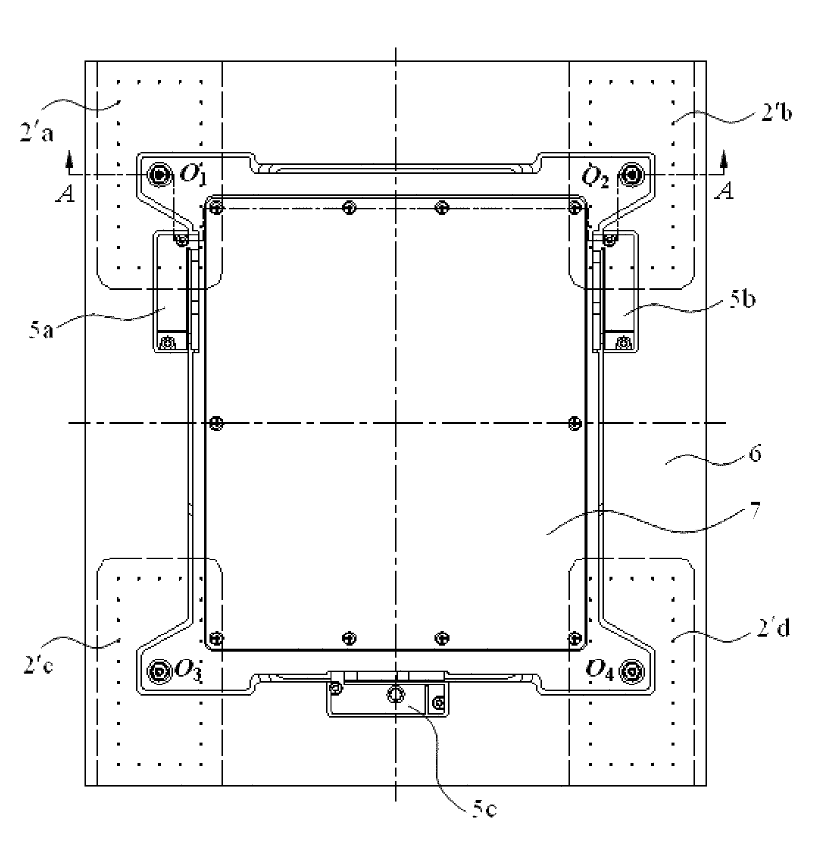
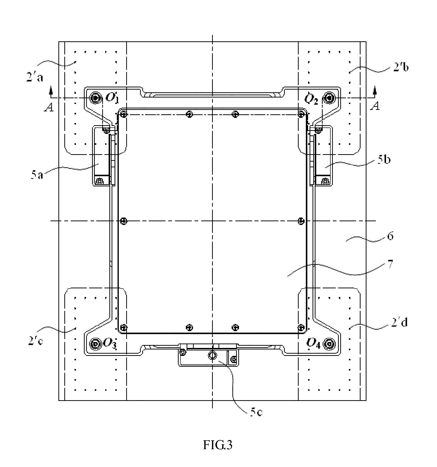
FIG. 3 depicts a top view of an aerostatic bearing embodying the present invention.
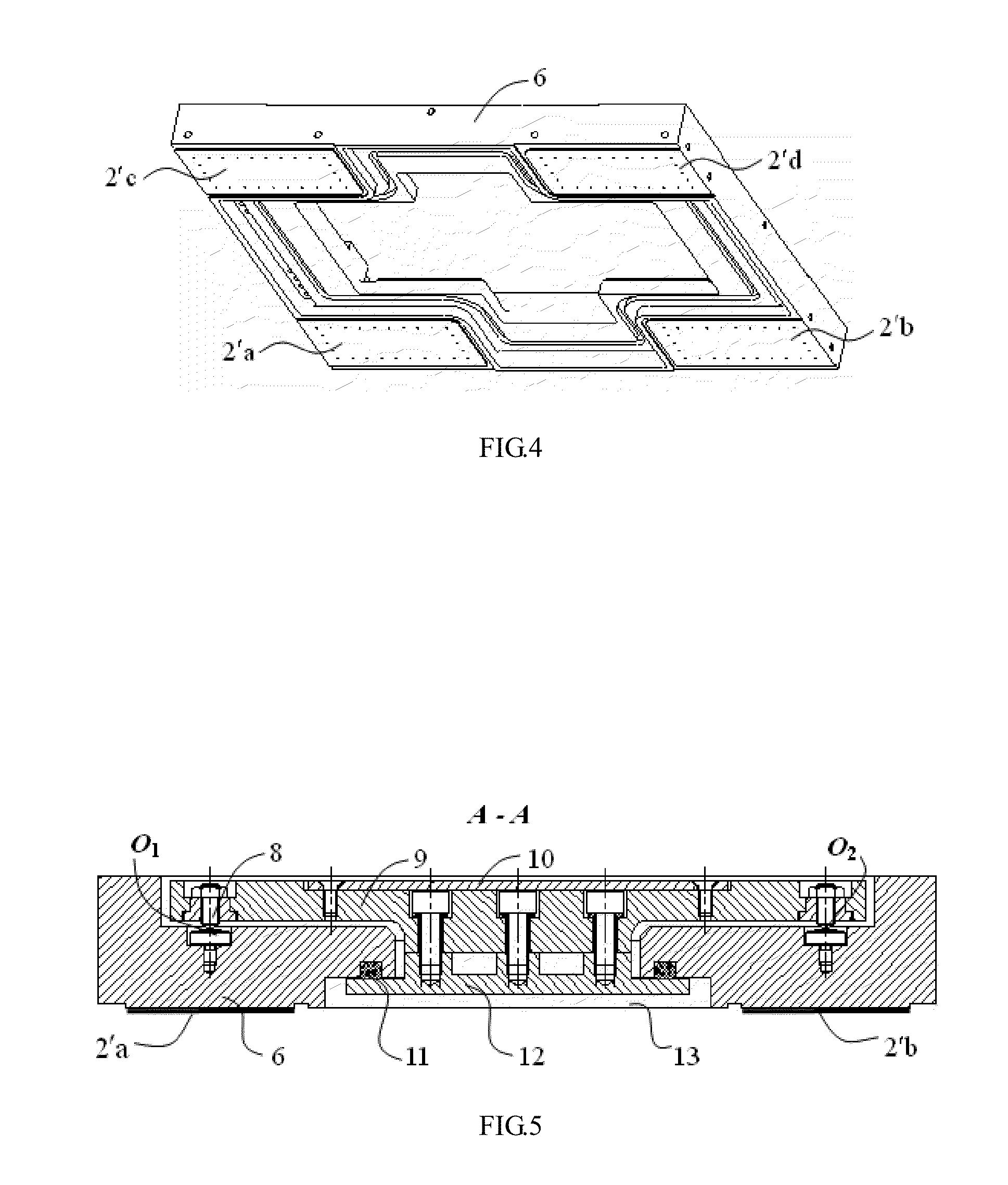
FIG. 4 depicts a bottom of the aerostatic bearing embodying the present invention.
FIG. 5 depicts a sectional view taken along the line A-A of FIG. 3.
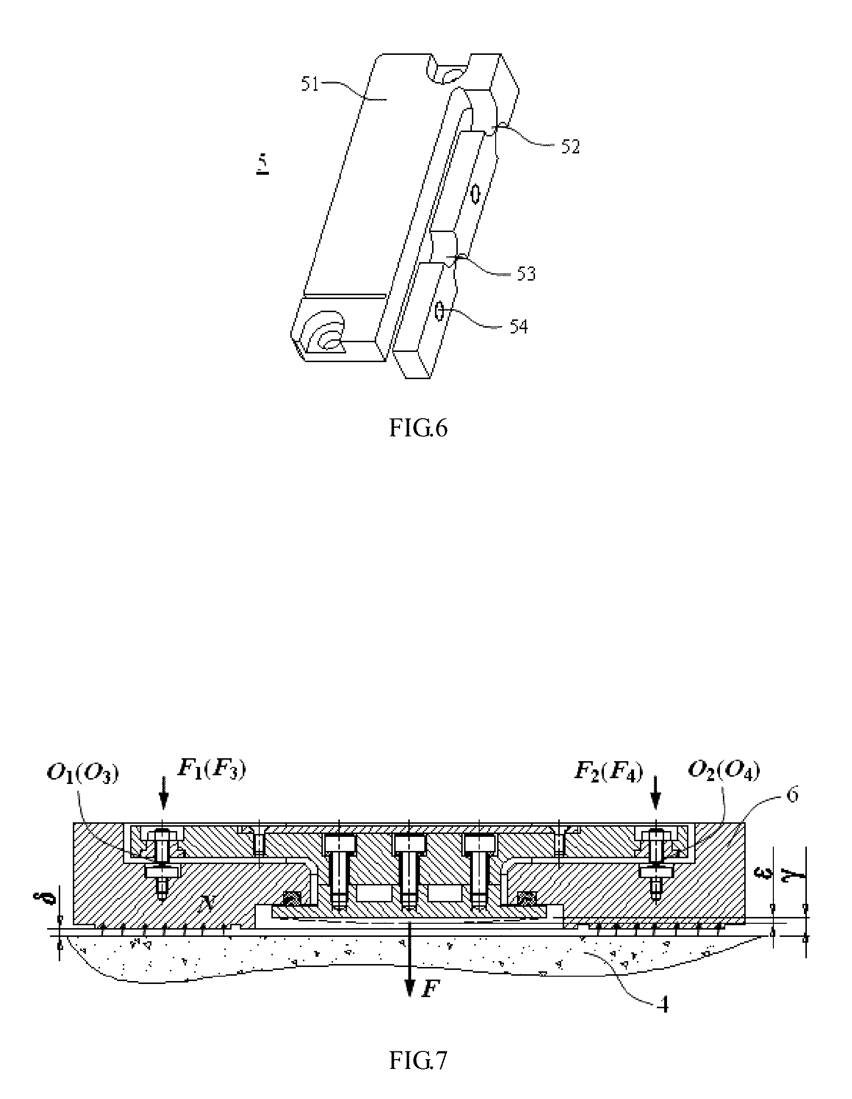
FIG. 6 schematically illustrates a flexible reed of the aerostatic bearing embodying the present invention.
FIG. 7 illustrates the operating mechanism of the aerostatic bearing embodying the present invention.
DETAILED DESCRIPTION OF THE INVENTION
Specific description of a split-type aerostatic bearing embodying the present invention will be provided below with reference to FIGS. 3 to 7.
The split-type aerostatic bearing includes an aerostatic bearing plate, air floating elements disposed on a bottom of the aerostatic bearing plate and a vacuum pre-tightening structure disposed on the aerostatic bearing plate. The vacuum pre-tightening structure is coupled to the aerostatic bearing plate in a split fashion. Each coupling point of the vacuum pre-tightening structure and the aerostatic bearing plate may be aligned on a same normal line of the platform with a center of a corresponding one of the air floating elements. A bottom surface of the vacuum pre-tightening structure may be configured at a higher level than a bottom surface of the aerostatic bearing plate. A vacuum chamber may be formed between the bottom surface of the vacuum pre-tightening structure and the bottom surface of the aerostatic bearing plate.
In the split-type aerostatic bearing embodying the present invention, the air floating elements are separated from the vacuum pre-tightening structure and each coupling point between the vacuum pre-tightening structure and the aerostatic bearing plate is aligned on a same normal line of the platform with the center of the corresponding air floating element, therefore, the corresponding application point of a vacuum pre-tightening force to the aerostatic bearing plate is also aligned on the same normal line of the platform with the center of the corresponding air floating element. This prevents the aerostatic bearing plate from bending out of shape and thus will not affect the normal operation of the aerostatic bearing.
A split-type aerostatic bearing embodying the present invention will now be described in detail below with reference to a specific embodiment.
In the embodiment, the split-type aerostatic bearing is a key component of a precision moving table. It can provide the moving table with gas bearing support and thereby can enable the moving table to make friction-free movement on a platform (which is generally a marble platform).
Turning now to FIGS. 3 to 4, the split-type aerostatic bearing includes an aerostatic bearing plate 6. Air floating elements 2'a, 2'b, 2'c, 2'd are disposed on the four corners of a bottom of the aerostatic bearing plate 6, respectively. Moreover, a vacuum pre-tightening structure 7 is also disposed on the aerostatic bearing plate 6.
The air floating elements 2'a, 2'b, 2'c, 2'd may be formed by shaping the aerostatic bearing plate 6. That is, the air floating elements 2'a, 2'b, 2'c, 2'd may be formed integrally with the aerostatic bearing plate 6.
The vacuum pre-tightening structure 7 is disposed on the aerostatic bearing plate 6 and coupled to the aerostatic bearing plate 6 in a split fashion.
Referring to FIG. 5, the vacuum pre-tightening structure 7 may include a vacuum plate 12, a vacuum plate fixing frame 9, and a capping plate 10.
The vacuum plate 12 is disposed on a bottom of the vacuum plate fixing frame 9.
The vacuum plate fixing frame 9 may be coupled to the aerostatic bearing plate 6 by support adjusting screws 8.
The capping plate 10 is disposed on a top of the vacuum plate fixing frame 9.
A bottom surface of the vacuum plate 12 may be configured at a higher level than a bottom surface of the aerostatic bearing plate 6, thereby forming a vacuum chamber 13 between the vacuum plate 12 and the aerostatic bearing plate 6.
With continuing reference to FIG. 5, the vacuum plate 12 is fixed on a bottom of the vacuum plate fixing frame 9 and the capping plate 10 is fixed on a top of the vacuum plate fixing frame 9 by screws, respectively.
A central part of an upper portion of the aerostatic bearing plate 6 may define a ladder-like hollow and the vacuum pre-tightening structure 7 is disposed in the hollow.
A rubber sealing ring 11 may be disposed between the vacuum plate 12 and the aerostatic bearing plate 6 to seal the vacuum chamber 13 formed between them.
In conjunction reference to FIG. 3, the vacuum plate fixing frame 9 may be coupled to the aerostatic bearing plate 6 in a manner that each of the four corners of the vacuum plate fixing frame is connected to the aerostatic bearing plate with one of the support adjusting screws 8.
Moreover, the four support adjusting screws 8 may be disposed at locations respectively on same normal lines of the platform 4 (as shown in FIG. 7) with centers O.sub.1, O.sub.2, O.sub.3, O.sub.4 of the corresponding air floating elements 2'a, 2'b, 2'c, 2'd.
With continuing reference to FIG. 5, the support adjusting screws 8 are configured to adjust the distance between the vacuum plate fixing frame 9 and the aerostatic bearing plate 6.
For instance, adjusting the support adjusting screws 8 can enable the vacuum plate fixing frame 9 to move upwards relative to the aerostatic bearing plate 6 (i.e., enables the distance between the vacuum plate fixing frame 9 and the aerostatic bearing plate 6 to be increased). The movement of the vacuum plate fixing frame 9 can also drive the vacuum plate 12 to move upwards to make the vacuum plate 12 squeeze the rubber sealing ring 11 more tightly, thereby providing the vacuum chamber 13 with a better sealing effect.
With further reference to FIG. 3, the vacuum plate fixing frame 9 may be positioned by three flexible reeds 5a, 5b, 5c in the horizontal direction to limit the horizontal translation and rotation freedom of the vacuum pre-tightening structure 7 in the horizontal plane.
The vacuum plate fixing frame 9 may assume an approximately rectangular shape and the three flexible reeds 5a, 5b, 5c are disposed on respective three edges of the vacuum plate fixing frame 9.
The three flexible reeds 5a, 5b, 5c may have the same structure, and any of them can be represented by the numeral 5 in FIG. 6. The flexible reed 5 may include a body 51, a first vertical reed 52 and a second vertical reed 53.
The first vertical reed 52 and the second vertical reed 53 may be arranged on a same side of the body 51 and the first vertical reed has one end coupled to the body 51 and the other end coupled to one end of the second vertical reed 53.
Moreover, the body 51 may be coupled to the aerostatic bearing plate 6 and both of the first and second vertical reeds 52, 53 are coupled to the vacuum plate fixing frame 9.
As shown in FIGS. 5 and 6, the body 51 may be fixed (vertically) on the aerostatic bearing plate 6 by screws and the first and second vertical reeds 52, 53 include a mounting hole 54 respectively configured to allow them to be coupled (horizontally) to the vacuum plate fixing frame 9.
The flexible reeds may have a high horizontal stiffness in order to prevent relative motions between the air floating elements and the vacuum pre-tightening structure when the aerostatic bearing is moving with the precision moving table. Meanwhile, the flexible reeds may have a low vertical stiffness so as to ensure the adjustability of the distance between the vacuum plate fixing frame 9 and the aerostatic bearing plate 6 by the support adjusting screws 8.
The operating mechanism of the split-type aerostatic bearing of the present invention will be described below with reference to FIG. 7.
When the split-type aerostatic bearing is operating, the aerostatic bearing plate 6 are supported by the aerostatic forces N generated by the four air floating elements 2'a, 2'b, 2'c, 2'd (i.e., each of the air floating elements applies an aerostatic forces N to the aerostatic bearing plate 6). Of each aerostatic force N, the application point is at the center of a corresponding air floating element and the application direction is upwards, perpendicular to the platform 4. When negative pressure gas is introduced into the vacuum chamber 13, it will generate a vacuum pre-tightening force F operated on the vacuum pre-tightening structure 7. The vacuum pre-tightening force F will thereafter cause the vacuum pre-tightening structure 7 to generate a force on the aerostatic bearing plate 6. As the vacuum pre-tightening structure 7 is coupled to the aerostatic bearing plate 6 by the four support adjusting screws 8, the force operated on the aerostatic bearing plate 6 can be resolved to four components F.sub.1, F.sub.2, F.sub.3, F.sub.4. In light of the discussion above, application points of the four components F1, F2, F3, F4 are respectively on same normal lines of the platform 4 with centers O.sub.1, O.sub.2, O.sub.3, O.sub.4 of the corresponding air floating elements 2'a, 2'b, 2'c, 2'd. Moreover, their application directions are all downwards, perpendicular to the platform 4 and there exists the relation, F=F.sub.1+F.sub.2+F.sub.3+F.sub.4. Therefore, as indicated in FIG. 7, each aerostatic force N is equal in magnitude to, opposite in direction to, and has the application point located on a same normal line of the platform 4 with, a corresponding one of the components F1, F2, F3, F4. Thus, the aerostatic bearing plate 6 will not be bent out of shape.
Moreover, vertical flexibility of the flexible reeds 5a, 5b, 5c can ensure application points of the four components F.sub.1, F.sub.2, F.sub.3, F.sub.4 to be located on same normal lines of the platform 4 with centers O.sub.1, O.sub.2, O.sub.3, O.sub.4 of the corresponding air floating elements 2'a, 2'b, 2'c, 2'd.
While bending may occur at a portion of the vacuum plate 12 under the vacuum pre-tightening force F (as shown by the dotted line in FIG. 7), as long as the amount of the bending .epsilon. is smaller than the distance .gamma. between the vacuum plate 12 and the platform 4 (before the vacuum plate 12 was bent), the bending of the vacuum plate 12 will not affect the movement of the aerostatic bearing at all. As indicated above, with the present invention, the value of the distance .gamma. can be controlled within an appropriate range by a proper structure design of the aerostatic bearing.
Conclusively, in the split-type aerostatic bearing of the present invention, the separation of the air floating elements from the vacuum pre-tightening structure and the alignment of the application points of the vacuum pre-tightening force with the corresponding centers of the air floating elements prevents the plate from bending out of shape and hence ensures the normal operation of the aerostatic bearing when to seek for a higher aerostatic stiffness by increasing the vacuum pre-tightening force.
Therefore, the split-type aerostatic bearing of the present invention meets the demand for a high aerostatic stiffness.
* * * * *
D00000
D00001
D00002
D00003
D00004
XML
uspto.report is an independent third-party trademark research tool that is not affiliated, endorsed, or sponsored by the United States Patent and Trademark Office (USPTO) or any other governmental organization. The information provided by uspto.report is based on publicly available data at the time of writing and is intended for informational purposes only.
While we strive to provide accurate and up-to-date information, we do not guarantee the accuracy, completeness, reliability, or suitability of the information displayed on this site. The use of this site is at your own risk. Any reliance you place on such information is therefore strictly at your own risk.
All official trademark data, including owner information, should be verified by visiting the official USPTO website at www.uspto.gov. This site is not intended to replace professional legal advice and should not be used as a substitute for consulting with a legal professional who is knowledgeable about trademark law.