Method and system for updating tuning parameters of a controller
Kihas December 31, 2
U.S. patent number 8,620,461 [Application Number 12/565,873] was granted by the patent office on 2013-12-31 for method and system for updating tuning parameters of a controller. This patent grant is currently assigned to Honeywell International, Inc.. The grantee listed for this patent is Dejan Kihas. Invention is credited to Dejan Kihas.


View All Diagrams
| United States Patent | 8,620,461 |
| Kihas | December 31, 2013 |
Method and system for updating tuning parameters of a controller
Abstract
A method and system for updating tuning parameters associated with a controller without repetitive compilation of a controller code. The controller code represents an algorithm associated with the controller and can be compiled separately from a data set representing a solution for an optimization problem and also from a data set representing parameters required for prediction. The algorithm can be implemented in a programming language code suitable for implementation on an embedded platform or other types of computer platforms. The data sets can be represented in a specified data structure and the variables associated with the data structure can be declared in the controller template code. The variables can be updated independently without varying the compiled code associated with the controller algorithm that is referring to the variables. The controller can also be updated while the controller actively performs online. Such an approach enables repetitive tuning of the controller without repetitive compilation of the code representing the controller algorithm.
| Inventors: | Kihas; Dejan (Burnaby, CA) | ||||||||||
|---|---|---|---|---|---|---|---|---|---|---|---|
| Applicant: |
|
||||||||||
| Assignee: | Honeywell International, Inc.
(Morristown, NJ) |
||||||||||
| Family ID: | 43384638 | ||||||||||
| Appl. No.: | 12/565,873 | ||||||||||
| Filed: | September 24, 2009 |
Prior Publication Data
| Document Identifier | Publication Date | |
|---|---|---|
| US 20110071653 A1 | Mar 24, 2011 | |
| Current U.S. Class: | 700/29; 700/37; 717/151 |
| Current CPC Class: | G05B 13/048 (20130101); G05B 13/042 (20130101); G05B 17/02 (20130101) |
| Current International Class: | G05B 13/02 (20060101) |
| Field of Search: | ;700/28-32 ;717/121,151 |
References Cited [Referenced By]
U.S. Patent Documents
| 3744461 | July 1973 | Davis |
| 4005578 | February 1977 | McInerney |
| 4055158 | October 1977 | Marsee |
| 4206606 | June 1980 | Yamada |
| 4252098 | February 1981 | Tomczak et al. |
| 4359991 | November 1982 | Stumpp et al. |
| 4383441 | May 1983 | Willis et al. |
| 4426982 | January 1984 | Lehner et al. |
| 4438497 | March 1984 | Willis et al. |
| 4440140 | April 1984 | Kawagoe et al. |
| 4456883 | June 1984 | Bullis et al. |
| 4485794 | December 1984 | Kimberley et al. |
| 4601270 | July 1986 | Kimberley et al. |
| 4616308 | October 1986 | Morshedi et al. |
| 4653449 | March 1987 | Kamei et al. |
| 4671235 | June 1987 | Hosaka |
| 4677559 | June 1987 | Van Bruck |
| 4735181 | April 1988 | Kaneko et al. |
| 4947334 | August 1990 | Massey et al. |
| 4962570 | October 1990 | Hosaka et al. |
| 5044337 | September 1991 | Williams |
| 5076237 | December 1991 | Hartman et al. |
| 5089236 | February 1992 | Clerc |
| 5094213 | March 1992 | Dudek et al. |
| 5095874 | March 1992 | Schnaibel et al. |
| 5108716 | April 1992 | Nishizawa |
| 5123397 | June 1992 | Richeson |
| 5150289 | September 1992 | Badavas |
| 5186081 | February 1993 | Richardson et al. |
| 5233829 | August 1993 | Komatsu |
| 5270935 | December 1993 | Dudek et al. |
| 5273019 | December 1993 | Matthews et al. |
| 5282449 | February 1994 | Takahashi et al. |
| 5293553 | March 1994 | Dudek et al. |
| 5349816 | September 1994 | Sanbayashi et al. |
| 5365734 | November 1994 | Takeshima |
| 5394322 | February 1995 | Hansen |
| 5394331 | February 1995 | Dudek et al. |
| 5398502 | March 1995 | Watanabe |
| 5408406 | April 1995 | Mathur et al. |
| 5431139 | July 1995 | Grutter et al. |
| 5452576 | September 1995 | Hamburg et al. |
| 5477840 | December 1995 | Neumann |
| 5560208 | October 1996 | Halimi et al. |
| 5570574 | November 1996 | Yamashita et al. |
| 5598825 | February 1997 | Neumann |
| 5609139 | March 1997 | Ueda et al. |
| 5611198 | March 1997 | Lane et al. |
| 5690086 | November 1997 | Kawano et al. |
| 5692478 | December 1997 | Nogi et al. |
| 5697339 | December 1997 | Esposito |
| 5704011 | December 1997 | Hansen et al. |
| 5746183 | May 1998 | Parke et al. |
| 5765533 | June 1998 | Nakajima |
| 5771867 | June 1998 | Amstutz et al. |
| 5785030 | July 1998 | Paas |
| 5788004 | August 1998 | Friedmann et al. |
| 5842340 | December 1998 | Bush et al. |
| 5846157 | December 1998 | Reinke et al. |
| 5893092 | April 1999 | Driscoll |
| 5942195 | August 1999 | Lecea et al. |
| 5964199 | October 1999 | Atago et al. |
| 5970075 | October 1999 | Wasada |
| 5974788 | November 1999 | Hepburn et al. |
| 5995895 | November 1999 | Watt et al. |
| 6029626 | February 2000 | Bruestle |
| 6035640 | March 2000 | Kolmanovsky et al. |
| 6048620 | April 2000 | Zhong |
| 6048628 | April 2000 | Hillmann et al. |
| 6055810 | May 2000 | Borland et al. |
| 6058700 | May 2000 | Yamashita et al. |
| 6067800 | May 2000 | Kolmanovsky et al. |
| 6076353 | June 2000 | Freudenberg et al. |
| 6105365 | August 2000 | Deeba et al. |
| 6122555 | September 2000 | Lu |
| 6134883 | October 2000 | Kato et al. |
| 6153159 | November 2000 | Engeler et al. |
| 6161528 | December 2000 | Akao et al. |
| 6170259 | January 2001 | Boegner et al. |
| 6171556 | January 2001 | Burk et al. |
| 6178743 | January 2001 | Hirota et al. |
| 6178749 | January 2001 | Kolmanovsky et al. |
| 6208914 | March 2001 | Ward et al. |
| 6216083 | April 2001 | Ulyanov et al. |
| 6233922 | May 2001 | Maloney |
| 6236956 | May 2001 | Mantooth et al. |
| 6237330 | May 2001 | Takahashi et al. |
| 6242873 | June 2001 | Drozdz et al. |
| 6263672 | July 2001 | Roby et al. |
| 6273060 | August 2001 | Cullen |
| 6279551 | August 2001 | Iwano et al. |
| 6312538 | November 2001 | Latypov et al. |
| 6314724 | November 2001 | Kakuyama et al. |
| 6321538 | November 2001 | Hasler |
| 6327361 | December 2001 | Harshavardhana et al. |
| 6338245 | January 2002 | Shimoda et al. |
| 6341487 | January 2002 | Takahashi et al. |
| 6347619 | February 2002 | Whiting et al. |
| 6360159 | March 2002 | Miller et al. |
| 6360541 | March 2002 | Waszkiewicz et al. |
| 6360732 | March 2002 | Bailey et al. |
| 6363715 | April 2002 | Bidner et al. |
| 6363907 | April 2002 | Arai et al. |
| 6379281 | April 2002 | Collins et al. |
| 6389803 | May 2002 | Surnilla et al. |
| 6425371 | July 2002 | Majima |
| 6427436 | August 2002 | Allansson et al. |
| 6431160 | August 2002 | Sugiyama et al. |
| 6445963 | September 2002 | Blevins et al. |
| 6446430 | September 2002 | Roth et al. |
| 6453308 | September 2002 | Zhao et al. |
| 6463733 | October 2002 | Asik et al. |
| 6463734 | October 2002 | Tamura et al. |
| 6466893 | October 2002 | Latwesen et al. |
| 6470682 | October 2002 | Gray, Jr. |
| 6470862 | October 2002 | Isobe et al. |
| 6470886 | October 2002 | Jestrabek-Hart |
| 6494038 | December 2002 | Kobayashi et al. |
| 6502391 | January 2003 | Hirota et al. |
| 6510351 | January 2003 | Blevins et al. |
| 6512974 | January 2003 | Houston et al. |
| 6513495 | February 2003 | Franke et al. |
| 6532433 | March 2003 | Bharadwaj et al. |
| 6546329 | April 2003 | Bellinger |
| 6550307 | April 2003 | Zhang et al. |
| 6553754 | April 2003 | Meyer et al. |
| 6560528 | May 2003 | Gitlin et al. |
| 6560960 | May 2003 | Nishimura et al. |
| 6571191 | May 2003 | York et al. |
| 6579206 | June 2003 | Liu et al. |
| 6591605 | July 2003 | Lewis |
| 6594990 | July 2003 | Kuenstler et al. |
| 6601387 | August 2003 | Zurawski et al. |
| 6612293 | September 2003 | Schweinzer et al. |
| 6615584 | September 2003 | Ostertag |
| 6625978 | September 2003 | Eriksson et al. |
| 6629408 | October 2003 | Murakami et al. |
| 6637382 | October 2003 | Brehob et al. |
| 6644017 | November 2003 | Takahashi et al. |
| 6647710 | November 2003 | Nishiyama et al. |
| 6647971 | November 2003 | Vaughan et al. |
| 6651614 | November 2003 | Flamig-Vetter et al. |
| 6662058 | December 2003 | Sanchez |
| 6666198 | December 2003 | Mitsutani |
| 6666410 | December 2003 | Boelitz et al. |
| 6671603 | December 2003 | Cari et al. |
| 6672052 | January 2004 | Taga et al. |
| 6672060 | January 2004 | Buckland et al. |
| 6679050 | January 2004 | Takahashi et al. |
| 6687597 | February 2004 | Sulatisky et al. |
| 6688283 | February 2004 | Jaye |
| 6694244 | February 2004 | Meyer et al. |
| 6694724 | February 2004 | Tanaka et al. |
| 6705084 | March 2004 | Allen et al. |
| 6718254 | April 2004 | Hashimoto et al. |
| 6718753 | April 2004 | Bromberg et al. |
| 6725208 | April 2004 | Hartman et al. |
| 6736120 | May 2004 | Surnilla |
| 6739122 | May 2004 | Kitajima et al. |
| 6742330 | June 2004 | Genderen |
| 6743352 | June 2004 | Ando et al. |
| 6748936 | June 2004 | Kinomura et al. |
| 6752131 | June 2004 | Poola et al. |
| 6752135 | June 2004 | McLaughlin et al. |
| 6758037 | July 2004 | Terada et al. |
| 6760631 | July 2004 | Berkowitz et al. |
| 6760657 | July 2004 | Katoh |
| 6760658 | July 2004 | Yasui et al. |
| 6770009 | August 2004 | Badillo et al. |
| 6772585 | August 2004 | Iihoshi et al. |
| 6779344 | August 2004 | Hartman et al. |
| 6779512 | August 2004 | Mitsutani |
| 6788072 | September 2004 | Nagy et al. |
| 6789533 | September 2004 | Hashimoto et al. |
| 6792927 | September 2004 | Kobayashi |
| 6804618 | October 2004 | Junk |
| 6814062 | November 2004 | Esteghlal et al. |
| 6817171 | November 2004 | Zhu |
| 6823667 | November 2004 | Braun et al. |
| 6823675 | November 2004 | Brunell et al. |
| 6826903 | December 2004 | Yahata et al. |
| 6827060 | December 2004 | Huh |
| 6827061 | December 2004 | Nytomt et al. |
| 6827070 | December 2004 | Fehl et al. |
| 6834497 | December 2004 | Miyoshi et al. |
| 6839637 | January 2005 | Moteki et al. |
| 6849030 | February 2005 | Yamamoto et al. |
| 6874467 | April 2005 | Hunt et al. |
| 6879906 | April 2005 | Makki et al. |
| 6904751 | June 2005 | Makki et al. |
| 6911414 | June 2005 | Kimura et al. |
| 6915779 | July 2005 | Sriprakash |
| 6920865 | July 2005 | Lyon |
| 6925372 | August 2005 | Yasui |
| 6925796 | August 2005 | Nieuwstadt et al. |
| 6928362 | August 2005 | Meaney |
| 6928817 | August 2005 | Ahmad |
| 6931840 | August 2005 | Strayer et al. |
| 6934931 | August 2005 | Plumer et al. |
| 6941033 | September 2005 | Taylor et al. |
| 6941744 | September 2005 | Tanaka |
| 6945033 | September 2005 | Sealy et al. |
| 6948310 | September 2005 | Roberts, Jr. et al. |
| 6953024 | October 2005 | Linna et al. |
| 6965826 | November 2005 | Andres et al. |
| 6968677 | November 2005 | Tamura |
| 6971258 | December 2005 | Rhodes et al. |
| 6973382 | December 2005 | Rodriguez et al. |
| 6978744 | December 2005 | Yuasa et al. |
| 6996975 | February 2006 | Radhamohan et al. |
| 7000379 | February 2006 | Makki et al. |
| 7013637 | March 2006 | Yoshida |
| 7016779 | March 2006 | Bowyer |
| 7028464 | April 2006 | Rosel et al. |
| 7039475 | May 2006 | Sayyarrodsari et al. |
| 7047938 | May 2006 | Flynn et al. |
| 7052434 | May 2006 | Makino et al. |
| 7055311 | June 2006 | Beutel et al. |
| 7059112 | June 2006 | Bidner et al. |
| 7063080 | June 2006 | Kita et al. |
| 7069903 | July 2006 | Surnilla et al. |
| 7082753 | August 2006 | Dalla Betta et al. |
| 7085615 | August 2006 | Persson et al. |
| 7106866 | September 2006 | Astorino et al. |
| 7107978 | September 2006 | Itoyama |
| 7111450 | September 2006 | Surnilla |
| 7111455 | September 2006 | Okugawa et al. |
| 7113835 | September 2006 | Boyden et al. |
| 7117046 | October 2006 | Boyden et al. |
| 7124013 | October 2006 | Yasui |
| 7149590 | December 2006 | Martin et al. |
| 7151976 | December 2006 | Lin |
| 7152023 | December 2006 | Das |
| 7155334 | December 2006 | Stewart et al. |
| 7165393 | January 2007 | Betta et al. |
| 7165399 | January 2007 | Stewart |
| 7168239 | January 2007 | Ingram et al. |
| 7182075 | February 2007 | Shahed et al. |
| 7184845 | February 2007 | Sayyarrodsari et al. |
| 7184992 | February 2007 | Polyak et al. |
| 7188637 | March 2007 | Dreyer et al. |
| 7194987 | March 2007 | Mogi |
| 7197485 | March 2007 | Fuller |
| 7200988 | April 2007 | Yamashita |
| 7204079 | April 2007 | Audoin |
| 7275374 | October 2007 | Stewart et al. |
| 7275415 | October 2007 | Rhodes et al. |
| 7292926 | November 2007 | Schmidt et al. |
| 7302937 | December 2007 | Ma et al. |
| 7321834 | January 2008 | Chu et al. |
| 7323036 | January 2008 | Boyden et al. |
| 7328577 | February 2008 | Stewart et al. |
| 7337022 | February 2008 | Wojsznis et al. |
| 7349776 | March 2008 | Spillane et al. |
| 7357125 | April 2008 | Kolavennu |
| 7375374 | May 2008 | Chen et al. |
| 7376471 | May 2008 | Das et al. |
| 7389773 | June 2008 | Stewart et al. |
| 7392129 | June 2008 | Hill et al. |
| 7398149 | July 2008 | Ueno et al. |
| 7400967 | July 2008 | Ueno et al. |
| 7413583 | August 2008 | Langer et al. |
| 7415389 | August 2008 | Stewart et al. |
| 7418372 | August 2008 | Nishira et al. |
| 7430854 | October 2008 | Yasui et al. |
| 7433743 | October 2008 | Pistikopoulos et al. |
| 7444191 | October 2008 | Caldwell et al. |
| 7444193 | October 2008 | Cutler |
| 7447554 | November 2008 | Cutler |
| 7467614 | December 2008 | Stewart et al. |
| 7469177 | December 2008 | Samad et al. |
| 7493236 | February 2009 | Mock et al. |
| 7515975 | April 2009 | Stewart |
| 7522963 | April 2009 | Boyden et al. |
| 7536232 | May 2009 | Boyden et al. |
| 7542842 | June 2009 | Hill et al. |
| 7577483 | August 2009 | Fan et al. |
| 7587253 | September 2009 | Rawlings et al. |
| 7591135 | September 2009 | Stewart |
| 7599749 | October 2009 | Sayyarrodsari et al. |
| 7599750 | October 2009 | Piche |
| 7627843 | December 2009 | Dozorets et al. |
| 7630868 | December 2009 | Turner et al. |
| 7634323 | December 2009 | Vermillion et al. |
| 7634417 | December 2009 | Boyden et al. |
| 7650780 | January 2010 | Hall |
| 7668704 | February 2010 | Perchanok et al. |
| 7698004 | April 2010 | Boyden et al. |
| 7702519 | April 2010 | Boyden et al. |
| 7743606 | June 2010 | Havlena et al. |
| 7752840 | July 2010 | Stewart |
| 7765792 | August 2010 | Rhodes et al. |
| 7793489 | September 2010 | Wang et al. |
| 7798938 | September 2010 | Matsubara et al. |
| 7826909 | November 2010 | Attarwala |
| 7831318 | November 2010 | Bartee et al. |
| 7840287 | November 2010 | Wojsznis et al. |
| 7844351 | November 2010 | Piche |
| 7844352 | November 2010 | Vouzis et al. |
| 7846299 | December 2010 | Backstrom et al. |
| 7850104 | December 2010 | Havlena et al. |
| 7856966 | December 2010 | Saitoh |
| 7860586 | December 2010 | Boyden et al. |
| 7862771 | January 2011 | Boyden et al. |
| 7877239 | January 2011 | Grichnik et al. |
| 7878178 | February 2011 | Stewart et al. |
| 7904280 | March 2011 | Wood |
| 7905103 | March 2011 | Larsen et al. |
| 7907769 | March 2011 | Sammak et al. |
| 7930044 | April 2011 | Attarwala |
| 7933849 | April 2011 | Bartee et al. |
| 7958730 | June 2011 | Stewart |
| 7987145 | July 2011 | Baramov |
| 7996140 | August 2011 | Stewart et al. |
| 8019911 | September 2011 | Dressler et al. |
| 8025167 | September 2011 | Schneider et al. |
| 8032235 | October 2011 | Sayyar-Rodsari |
| 8078291 | December 2011 | Pekar et al. |
| 8109255 | February 2012 | Stewart et al. |
| 2002/0116104 | August 2002 | Kawashima et al. |
| 2003/0089102 | May 2003 | Colignon et al. |
| 2003/0150961 | August 2003 | Boelitz et al. |
| 2004/0006973 | January 2004 | Makki et al. |
| 2004/0034460 | February 2004 | Folkerts et al. |
| 2004/0086185 | May 2004 | Sun |
| 2004/0117766 | June 2004 | Mehta et al. |
| 2004/0118107 | June 2004 | Ament |
| 2004/0165781 | August 2004 | Sun |
| 2004/0199481 | October 2004 | Hartman et al. |
| 2004/0221889 | November 2004 | Dreyer et al. |
| 2004/0226287 | November 2004 | Edgar et al. |
| 2005/0143952 | June 2005 | Tomoyasu et al. |
| 2005/0171667 | August 2005 | Morita |
| 2005/0187643 | August 2005 | Sayyar-Rodsari et al. |
| 2005/0193739 | September 2005 | Brunell et al. |
| 2005/0209714 | September 2005 | Rawlings et al. |
| 2005/0210868 | September 2005 | Funabashi |
| 2006/0047607 | March 2006 | Boyden et al. |
| 2006/0111881 | May 2006 | Jackson |
| 2006/0137346 | June 2006 | Stewart et al. |
| 2006/0168945 | August 2006 | Samad et al. |
| 2006/0265203 | November 2006 | Jenny et al. |
| 2006/0282178 | December 2006 | Das et al. |
| 2007/0142936 | June 2007 | Denison et al. |
| 2007/0144149 | June 2007 | Kolavennu et al. |
| 2007/0156259 | July 2007 | Baramov et al. |
| 2007/0275471 | November 2007 | Coward |
| 2008/0071395 | March 2008 | Pachner |
| 2008/0097625 | April 2008 | Vouzis et al. |
| 2008/0103747 | May 2008 | Macharia et al. |
| 2008/0103748 | May 2008 | Axelrud et al. |
| 2008/0104003 | May 2008 | Macharia et al. |
| 2008/0109100 | May 2008 | Macharia et al. |
| 2008/0125875 | May 2008 | Stewart et al. |
| 2008/0132178 | June 2008 | Chatterjee et al. |
| 2008/0183311 | July 2008 | MacArthur et al. |
| 2008/0208778 | August 2008 | Sayyar-Rodsari et al. |
| 2008/0244449 | October 2008 | Morrison et al. |
| 2009/0005889 | January 2009 | Sayyar-Rodsari |
| 2009/0008351 | January 2009 | Schneider et al. |
| 2009/0043546 | February 2009 | Srinivasan et al. |
| 2009/0131216 | May 2009 | Matsubara et al. |
| 2009/0182518 | July 2009 | Chu et al. |
| 2009/0198350 | August 2009 | Thiele |
| 2009/0240480 | September 2009 | Baramov |
| 2009/0254202 | October 2009 | Pekar et al. |
| 2009/0287320 | November 2009 | MacGregor et al. |
| 2009/0312998 | December 2009 | Berckmans et al. |
| 2010/0017094 | January 2010 | Stewart et al. |
| 2010/0038158 | February 2010 | Whitney et al. |
| 2010/0050607 | March 2010 | He et al. |
| 2010/0122523 | May 2010 | Vosz |
| 2010/0204808 | August 2010 | Thiele |
| 2010/0268353 | October 2010 | Crisalle et al. |
| 2010/0300070 | December 2010 | He et al. |
| 2010/0305719 | December 2010 | Pekar et al. |
| 2010/0327090 | December 2010 | Havlena et al. |
| 2011/0006025 | January 2011 | Schneider et al. |
| 2011/0010073 | January 2011 | Stewart et al. |
| 2011/0029235 | February 2011 | Berry |
| 2011/0046752 | February 2011 | Piche |
| 2011/0060424 | March 2011 | Havlena |
| 2011/0066308 | March 2011 | Yang et al. |
| 2011/0087420 | April 2011 | Stewart et al. |
| 2011/0104015 | May 2011 | Boyden et al. |
| 2011/0125293 | May 2011 | Havlena |
| 2011/0167025 | July 2011 | Danai et al. |
| 2011/0270505 | November 2011 | Chaturvedi et al. |
| 2011/0301723 | December 2011 | Pekar et al. |
| 2012/0010732 | January 2012 | Stewart et al. |
| 2012/0116649 | May 2012 | Stewart et al. |
| 19628796 | Oct 1997 | DE | |||
| 10219832 | Nov 2002 | DE | |||
| 0301527 | Feb 1989 | EP | |||
| 0950803 | Apr 1999 | EP | |||
| 1134368 | Mar 2001 | EP | |||
| 1180583 | Feb 2002 | EP | |||
| 1221544 | Jul 2002 | EP | |||
| 1225490 | Jul 2002 | EP | |||
| 1245811 | Oct 2002 | EP | |||
| 1686251 | Aug 2006 | EP | |||
| 2107439 | Oct 2009 | EP | |||
| 2146258 | Jan 2010 | EP | |||
| 59190443 | Oct 1984 | JP | |||
| 2010282618 | Dec 2010 | JP | |||
| 0232552 | Apr 2002 | WO | |||
| WO 02/101208 | Dec 2002 | WO | |||
| 03048533 | Jun 2003 | WO | |||
| WO 03/065135 | Aug 2003 | WO | |||
| WO 03/078816 | Sep 2003 | WO | |||
| WO 2004/027230 | Apr 2004 | WO | |||
| WO 2008/033800 | Mar 2008 | WO | |||
| WO 2008/033800 | Mar 2008 | WO | |||
| 2008115911 | Sep 2008 | WO | |||
Other References
|
Alberto Bemporad, "Model Predictive Control Design: New Trends and Tools", Proceedings of 45.sup.th IEEE Conference on Decision & Control, pp. 6678-6683, Dec. 13-15, 2006. cited by examiner . U.S. Appl. No. 12/174,910, filed Jul. 17, 2008, Stewart et al. cited by applicant . "MPC Implementation Methods for the Optimization of the Response of Control Valves to Reduce Variability," Advanced Application Note 002 Rev A. (2007) Fisher-Rosemount Systems, Jan. 3, pp. 1-10. cited by applicant . Bemporad, A. et al., "Model Predictive Control Toolbox.TM. Release Notes," Math Works Inc., Natick, MA Oct. 2008. cited by applicant . Mayne, D. Q. et al., "Constrained model predictive control: Stability and optimality," Automatica (2000) 36:789-814. cited by applicant . Rawlings, J. B., "Tutorial Overview of Model Predictive Control," IEEE Control Systems Magazine (Jun. 2000), pp. 38-52. cited by applicant . Marjanovic, O. et al., "Towards a Simplified Infinite Horizon Model Predictive Controller," Proceedings of the 5th Asian Control Conference, Jul. 20-23, 2004. cited by applicant . Maciejowski, J. M., Predictive Control with Constraints (2002) Prentice Hall, Pearson Education Limited, Harlow, England. cited by applicant . Qin, S. J. et al., "A survey of industrial model predictive control technology," Control Engineering Practice (2003) 11:733-764. cited by applicant . Borrelli, F., "Constrained Optimal Control of Linear and Hybrid Systems," Lecture Notes in Control and Information Sciences Feb. 20, 2003, Springer, Berlin. cited by applicant . Borrelli, F., "Discrete Time Constrained Optimal Control," A dissertation submitted to the Swiss Federal Instituted of Technology (ETH) Oct. 9, 2002, Zurich, Diss. ETH No. 14666. cited by applicant . Tondel, P. et al., "An algorithm for multi-parametric quadratic programming and explicit MPC solutions," Automatica (2003) 39:489-497. cited by applicant . Bemporad, A. et al., "The explicit linear quadratic regulator for constrained systems," Automatica (2002) 38:3-20. cited by applicant . Bemporad, A. et al., "Model Predictive Control Based on Linear Programming--The Explicit Solution," IEEE Transactions on Automatic Control Dec. 2002, 47(12):1974-1985. cited by applicant . Stewart, G. et al., "A Model Predictive Control Framework for Industrial Turbodiesel Engine Control," in Proc. 47th IEEE Conf. on Decision and Control (2008) Mexico, December. cited by applicant . Johansen, T. A. et al., "Hardware Synthesis of Explicit Model Predictive Controllers," IEEE Transactions on Control Systems Technology (2007) vol. 15, No. 1, January. cited by applicant . Johansen, T. A. et al., "Hardware Architecture Design for Explicit Model Predictive Control," Proceedings of ACC (2006). cited by applicant . Schauffele, J. et al., Automotive Software Engineering Principles, Processes, Methods, and Tools (2005) SAE International, Warrendale, PA. cited by applicant . Mariethoz, S. et al., "Sensorless Explicit Model Predictive Control of the DC-DC Buck Converter with Inductor Current Limitation," Applied Power Electronics Conference and Exposition, Twenty-Third IEEE APEC (2008) pp. 1710-1715. cited by applicant . Stewart, G. et al., "A Modular Model Predictive Controller for Turbodiesel Problems," First Workshop on Automotive Model Predictive Control, Schloss Muhldorf, Feldkirchen, Johannes Kepler University Linz (2009). cited by applicant . Ortner, P. et al., "Predictive Control of a Diesel Engine Air Path," IEEE Transactions on Control Systems Technology (2007) 15(3):449-456. cited by applicant . Ortner, P. et al., "MPC for a Diesel Engine Air Path using an Explicit Approach for Constraint Systems," Proceedings of the 2006 IEEE, International Conference on Control Applications (2006) Munich, Germany, Oct. 4-6, pp. 2760-2765. cited by applicant . Borrelli, F. et al., "An MPC/Hybrid System Approach to Traction Control," IEEE Transactions on Control Systems Technology (2006) 14(3):541-552. cited by applicant . Bemporad, A. et al., Model Predictive Control Toolbox.TM. 3 User's Guide (2008) Matlab Mathworks, Natick, MA. cited by applicant . Pannocchia, G. et al., "Combined Design of Disturbance Model and Observer for Offset-free Model Predictive Control," IEEE Trans. on Automatic Control (2007) 52(6). cited by applicant . International Application Status Report for WO 2008/033800. cited by applicant . Boom et al., "MPC for Max-Plus-Linear Systems: Closed-Loop Behavior and Tuning", Jun. 2001, Proceedings of the 2001 American Control Conference, Arlington, VA, pp. 325-300. cited by applicant . Bunting, "Increased Urea Dosing Could Cut SCR Truck Running Costs", http://www.automotiveworld.com/article/85897-increased-urea-dosing-could-- cut-scr-truck-running-costs, Automotive World, 3 pages, Feb. 24, 2011, printed Mar. 2, 2011. cited by applicant . U.S. Appl. No. 13/236,217. cited by applicant . U.S. Appl. No. 13/290,012. cited by applicant . Keulen et al., "Predictive Cruise Control in Hybrid Electric Vehicles", May 2009, World Electric Journal, vol. 3, ISSN 2032-6653. cited by applicant . Schutter et al., "Model Predictive Control for Max-Min-Plus-Scaling Systems", Jun. 2001, Proceedings of the 2001 American Control Conference, Arlington, VA, pp. 319-324. cited by applicant . "SCR, 400-csi Coated Catalyst," Leading NOx Control Technologies Status Summary, 1 page prior to Feb. 2, 2005. cited by applicant . Advanced Petroleum-Based Fuels-Diesel Emissions Control (APBF-DEC) Project, "Quarterly Update," No. 7, 6 pages, Fall 2002. cited by applicant . Allanson, et al., "Optimizing the Low Temperature Performance and Regeneration Efficiency of the Continuously Regenerating Diesel Particulate Filter System," SAE Paper No. 2002-01-0428, 8 pages, Mar. 2002. cited by applicant . Amstuz, et al., "EGO Sensor Based Robust Output Control of EGR in Diesel Engines," IEEE TCST, vol. 3, No. 1, 12 pages, Mar. 1995. cited by applicant . Bemporad, et al., "Explicit Model Predictive Control," 1 page, prior to Feb. 2, 2005. cited by applicant . Bertsekas, "On the Goldstein-Levitin-Polyak Gradient Projection Method," IEEE Transactions on Automatic Control, vol. AC-21, No. 2, pp. 174-184, Apr. 1976. cited by applicant . Bertsekas, "Projected Newton Methods for Optimization Problems with Simple Constraints," SIAM J. Control and Optimization, vol. 20, No. 2, pp. 221-246, Mar. 1982. cited by applicant . Borrelli, "Constrained Optimal Control of Linear and Hybrid Systems," Lecture Notes in Control and Information Sciences, vol. 290, 2003. cited by applicant . Catalytica Energy Systems, "Innovative NOx Reduction Solutions for Diesel Engines," 13 pages, 3rd Quarter, 2003. cited by applicant . Chatterjee, et al. "Catalytic Emission Control for Heavy Duty Diesel Engines," JM, 46 pages, prior to Feb. 2, 2005. cited by applicant . U.S. Appl. No. 13/353,178, filed Jan. 18, 2012. cited by applicant . De Schutter et al., "Model Predictive Control for Max-Min-Plus-Scaling Systems," Proceedings of the 2001 American Control Conference, Arlington, VA, pp. 319-324, Jun. 2001. cited by applicant . Delphi, Delphi Diesel NOx Trap (DNT), 3 pages, Feb. 2004. cited by applicant . Diehl et al., "Efficient Numerical Methods for Nonlinear MPC and Moving Horizon Estimation," Int. Workshop on Assessment and Future Directions of NMPC, 24 pages, Pavia, Italy, Sep. 5-9, 2008. cited by applicant . GM "Advanced Diesel Technology and Emissions," powertrain technologies--engines, 2 pages, prior to Feb. 2, 2005. cited by applicant . Guerreiro et al., "Trajectory Tracking Nonlinear Model Predictive Control for Autonomous Surface Craft," Proceedings of the European Control Conference, Budapest, Hungary, 6 pages, Aug. 2009. cited by applicant . Guzzella, et al., "Control of Diesel Engines," IEEE Control Systems Magazine, pp. 53-71, Oct. 1998. cited by applicant . Havelena, "Componentized Architecture for Advanced Process Management," Honeywell International, 42 pages, 2004. cited by applicant . Hiranuma, et al., "Development of DPF System for Commercial Vehicle--Basic Characteristic and Active Regeneration Performance," SAE Paper No. 2003-01-3182, Mar. 2003. cited by applicant . Honeywell, "Profit Optimizer a Distributed Quadratic Program (DQP) Concepts Reference," 48 pages, prior to Feb. 2, 2005. cited by applicant . http://www.not2fast.wryday.com/turbo/glossary/turbo.sub.--glossary.shtml, "Not2Fast: Turbo Glossary," 22 pages, printed Oct. 1, 2004. cited by applicant . http://www.tai-cwv.com/sbl106.0.html, "Technical Overview--Advanced Control Solutions," 6 pages, printed Sep. 9, 2004. cited by applicant . Jonsson, "Fuel Optimized Predictive Following in Low Speed Conditions," Master's Thesis, 46 pages, Jun. 28, 2003. cited by applicant . Kelly, et al., "Reducing Soot Emissions from Diesel Engines Using One Atmosphere Uniform Glow Discharge Plasma," SAE Paper No. 2003-01-1183, Mar. 2003. cited by applicant . Kolmanovsky, et al., "Issues in Modeling and Control of Intake Flow in Variable Geometry Turbocharged Engines", 18th IFIP Conf. System Modeling and Optimization, pp. 436-445, Jul. 1997. cited by applicant . Kulhavy, et al. "Emerging Technologies for Enterprise Optimization in the Process Industries," Honeywell, 12 pages, Dec. 2000. cited by applicant . Locker, et al., "Diesel Particulate Filter Operational Characterization," Corning Incorporated, 10 pages, prior to Feb. 2, 2005. cited by applicant . Lu, "Challenging Control Problems and Engineering Technologies in Enterprise Optimization," Honeywell Hi-Spec Solutions, 30 pages, Jun. 4-6, 2001. cited by applicant . Mehta, "The Application of Model Predictive Control to Active Automotive Suspensions," 56 pages, May 17, 1996. cited by applicant . Moore, "Living with Cooled-EGR Engines," Prevention Illustrated, 3 pages, Oct. 3, 2004. cited by applicant . Murayama et al., "Speed Control of Vehicles with Variable Valve Lift Engine by Nonlinear MPC," ICROS-SICE International Joint Conference, pp. 4128-4133, 2009. cited by applicant . National Renewable Energy Laboratory (NREL), "Diesel Emissions Control- Sulfur Effects Project (DECSE) Summary of Reports," U.S. Department of Energy, 19 pages, Feb. 2002. cited by applicant . Salvat, et al., "Passenger Car Serial Application of a Particulate Filter System on a Common Rail Direct Injection Engine," SAE Paper No. 2000-01-0473, 14 pages, Feb. 2000. cited by applicant . Shamma, et al. "Approximate Set-Valued Observers for Nonlinear Systems," IEEE Transactions on Automatic Control, vol. 42, No. 5, May 1997. cited by applicant . Soltis, "Current Status of NOx Sensor Development," Workshop on Sensor Needs and Requirements for PEM Fuel Cell Systems and Direct-Injection Engines, 9 pages, Jan. 25-26, 2000. cited by applicant . Stefanopoulou, et al., "Control of Variable Geometry Turbocharged Diesel Engines for Reduced Emissions," IEEE Transactions on Control Systems Technology, vol. 8, No. 4, pp. 733-745, Jul. 2000. cited by applicant . Storset, et al., "Air Charge Estimation for Turbocharged Diesel Engines," vol. 1 Proceedings of the American Control Conference, 8 pages, Jun. 28-30, 2000. cited by applicant . The MathWorks, "Model-Based Calibration Toolbox 2.1 Calibrate complex powertrain systems," 4 pages, prior to Feb. 2, 2005. cited by applicant . The MathWorks, "Model-Based Calibration Toolbox 2.1.2," 2 pages, prior to Feb. 2, 2005. cited by applicant . Theiss, "Advanced Reciprocating Engine System (ARES) Activities at the Oak Ridge National Lab (ORNL), Oak Ridge National Laboratory," U.S. Department of Energy, 13 pages, Apr. 14, 2004. cited by applicant . Van Basshuysen et al., "Lexikon Motorentechnik," (Dictionary of Automotive Technology) published by Vieweg Verlag, Wiesbaden 039936, p. 518, 2004. (English Translation). cited by applicant . Van Den Boom et al., "MPC for Max-Plus-Linear Systems: Closed-Loop Behavior and Tuning," Proceedings of the 2001 American Control Conference, Arlington, VA, pp. 325-330, Jun. 2001. cited by applicant . Van Keulen et al., "Predictive Cruise Control in Hybrid Electric Vehicles," World Electric Vehicle Journal vol. 3, ISSN 2032-6653, pp. 1-11, 2009. cited by applicant . Wang et al., "Fast Model Predictive Control Using Online Optimization," Proceedings of the 17.sup.th World Congress, the International Federation of Automatic Control, Seoul, Korea, pp. 6974-6979, Jul. 6-11, 2008. cited by applicant . Wang et al., "PSO-Based Model Predictive Control for Nonlinear Processes," Advances in Natural Computation, Lecture Notes in Computer Science, vol. 3611/2005, 8 pages, 2005. cited by applicant . Zavala et al., "The Advance-Step NMPC Controller: Optimality, Stability, and Robustness," Automatica, vol. 45, pp. 86-93, 2009. cited by applicant . Zeilinger et al., "Real-Time MPC--Stability Through Robust MPC Design," Joint 48.sup.th IEEE Conference on Decision and Control and 28.sup.th Chinese Control Conference, Shanghai, P.R. China, pp. 3980-3986, Dec. 16-18, 2009. cited by applicant . Zelenka, et al., "An Active Regeneration as a Key Element for Safe Particulate Trap Use," SAE Paper No. 2001-0103199, 13 pages, Feb. 2001. cited by applicant . Zhu, "Constrained Nonlinear Model Predictive Control for Vehicle Regulation," Dissertation, Graduate School of the Ohio State University, 125 pages, 2008. cited by applicant . International Search Report for Corresponding Serial No. EP10175270 dated Jan. 16, 2013. cited by applicant . "Model Predictive Control," Wikipedia, pp. 1-5, Jan. 22, 2009. http://en.wikipedia.org/w/index.php/title=Special:Book&bookcmd=download&c- ollecton.sub.--id=641cd1b5da77cc22&writer=rl&return.sub.--to=Model predictive control, retrieved Nov. 20, 2012. cited by applicant . Axehill et al., "A Dual Gradiant Projection Quadratic Programming Algorithm Tailored for Model Predictive Control," Proceedings of the 47th IEEE Conference on Decision and Control, Cancun Mexico, pp. 3057-3064, Dec. 9-11, 2008. cited by applicant . Axehill et al., "A Dual Gradient Projection Quadratic Programming Algorithm Tailored for Mixed Integer Predictive Control," Technical Report from Linkopings Universitet, Report No. Li-Th-ISY-R-2833, 58 pages, Jan. 31, 2008. cited by applicant . Baffi et al., "Non-Linear Model Based Predictive Control Through Dynamic Non-Linear Partial Least Squares," Trans IChemE, vol. 80, Part A, pp. 75-86, Jan. 2002. cited by applicant . Search Report for Corresponding EP Application No. 11167549.2 dated Nov. 27, 2012. cited by applicant . U.S. Appl. No. 13/290,025, filed Nov. 2011. cited by applicant . De Oliveira, "Constraint Handling and Stability Properties of Model Predictive Control," Carnegie Institute of Technology, Department of Chemical Engineering, Paper 197, 64 pages, Jan. 1, 1993. cited by applicant . Dunbar, "Model Predictive Control: Extension to Coordinated Multi-Vehicle Formations and Real-Time Implementation," CDS Technical Report 01-016, 64 pages, Dec. 7, 2001. cited by applicant . Patrinos et al., "A Global Piecewise Smooth Newton Method for Fast Large-Scale Model Predictive Control," Tech Report TR2010-02, National Technical University of Athens, 23 pages, 2010. cited by applicant . Rajamani, "Data-based Techniques to Improve State Estimation in Model Predictive Control," Ph.D. Dissertation, 257 pages, 2007. cited by applicant . Takacs et al., "Newton-Raphson Based Efficient Model Predictive Control Applied on Active Vibrating Structures," Proceeding of the European Control Conference 2009, Budapest, Hungary, pp. 2845-2850, Aug. 23-26, 2009. cited by applicant . Wright, "Applying New Optimization Algorithms to Model Predictive Control," 5th International Conference on Chemical Process Control, 10 pages, 1997. cited by applicant. |
Primary Examiner: Ali; Mohammad
Assistant Examiner: Laughlin; Nathan
Attorney, Agent or Firm: Seager Tufte & Wickhem LLC.
Claims
What is claimed is:
1. A system for updating tuning parameters of a controller, said system comprising: a controller accessing a memory having one or more memory units for storing a first data set for use with a compiled controller template and a second data set for use with the compiled controller template; a processor; a computer-usable medium embodying computer program code, said computer program code comprising instructions executable by said processor and configured for: identifying a compiled controller template for operating the controller, the compiled controller template including an algorithm representing a dynamic operating process of a system to be controlled by the controller; generating the first data set indicative of an explicit control law associated with a solution to a model predictive control optimization problem related to the dynamic operating process of the system, wherein the first data set is associated with a specified data structure having said at least one data set; and updating variables to generate a second data set, separate from the first data set; and enabling the controller to switch from using the first data set to using the second data set without altering said compiled controller template in order to repeatedly tune said controller without performing a recompilation with respect to said compiled controller template.
2. The system of claim 1, wherein said instructions are further configured for compiling a controller template to generate the compiled controller template.
3. The system of claim 1, wherein said instructions are further configured for updating said controller without performing said recompilation.
4. The system of claim 1, wherein said instructions are further configured for updating said controller with the second data set without halting operations of said controller.
5. The system of claim 1, wherein said instructions are further configured for updating said controller with the second data set online in order to seamlessly update at least one observer data set and ensure a flawless transfer of data thereof.
6. The system of claim 5, wherein updating said controller without performing said recompilation further comprises: varying a tuning parameter associated with an offline optimization application in order to generate the second data set; transferring said second data set to said memory via a data communications channel without halting operations associated with said controller; and switching the controller from operating the compiled control template using the first data set to operating the compiled control template using the second data set.
7. The system of claim 6, wherein updating said controller without halting operations of said controller further comprises: configuring a data loader to perform a tuning parameter update without halting said controller, wherein said data loader copies data from a first memory location to a second memory location of the memory.
8. A computer-usable medium for updating tuning parameters of a controller, said computer-usable medium embodying computer program code in a non-transient form, said computer program code comprising computer executable instructions configured for: generating a first data set indicative of an explicit control law associated with a solution to first model predictive control optimization problem, wherein the first data set has a specified data structure; compiling a first controller template indicative of a first controller separate from the first data set, in order to generate a compiled controller template for implementation on a computer platform; generating a second data set indicative of an explicit control law associated with a solution to a second model predictive control optimization problem, wherein the second data set has the specified data structure; compiling a second controller template indicative of a second controller separate from the second data set, in order to generate a compiled controller template for implementation on a computer platform; and switching the controller from operating with the first controller template and the first data set to operating with the second controller template and the second data set, wherein the controller switches between the first controller template and the second controller template without disrupting operation of the controller.
9. The computer-usable medium of claim 8, wherein said controller comprises a MPC-based controller.
10. The computer-usable medium of claim 8, wherein said embodied computer program code further comprises computer executable instructions configured for: updating said controller without performing said recompilation process; updating said controller without halting operations of said controller; and updating said controller online in order to seamlessly update at least one observer data set and ensure a flawless transfer of data thereof.
Description
TECHNICAL FIELD
Embodiments are generally related to control systems and controller devices. Embodiments are additionally related to MPC (Model-based Predictive Control) methods and systems. Embodiments also relate in general to the field of computers and similar technologies and, in particular to, software utilized in this field. In addition, embodiments relate to the updating of tuning parameters associated with controllers.
BACKGROUND OF THE INVENTION
A common approach utilized in advanced industrial control processes is Model-based Predictive Control, also known as "MPC". MPC involves the use of a controller that utilizes a mathematical model of a process to predict the future behavior of the control system and then formulates the control problem as a constrained optimization problem. The accuracy of the internal process model is crucial to the performance of a controller based on the solution of a constrained optimization problem.
MPC is thus a standard control and optimization technique utilized in process control such as, for example, power train control applications in diesel engines, turbocharger control solutions, and so forth. The acronym "MPC" therefore generally refers to a class of algorithms, which utilize an internal mathematical model of a controlled system and an optimization algorithm to compute optimal future control actions for system inputs and optimal trajectories at system outputs, for example, control actions for automotive system inputs.
Explicit MPC-based approaches require a large amount of data that is descriptive of a resulting control law. Consequently, a large amount of data is required to be transferred to and stored in an embedded system. Typically, for any change associated with plant models, weightings or other parameters in a cost function of an optimization problem, the solution must be recalculated and a set of data, which describe the solution, regenerated. The resulting set of data may then be redeployed to an embedded system or other types of computer platforms. Note that the term "platform" as utilized herein may also refer to a "real-time target platform" or a "real-time platform" or a "real-time target".
Currently, the procedure for updating control law information requires recompilation of a controller code along with a solution data set and redeployment of the compiled controller code. Frequent re-tuning of the controller during a development phase is always a necessity and presents a problem; hence, re-compilation and redeployment of the controller consumes a great deal of time during the development and test phases. For example, currently, if there are required ten tuning iterations, the controller needs to be recompiled ten times.
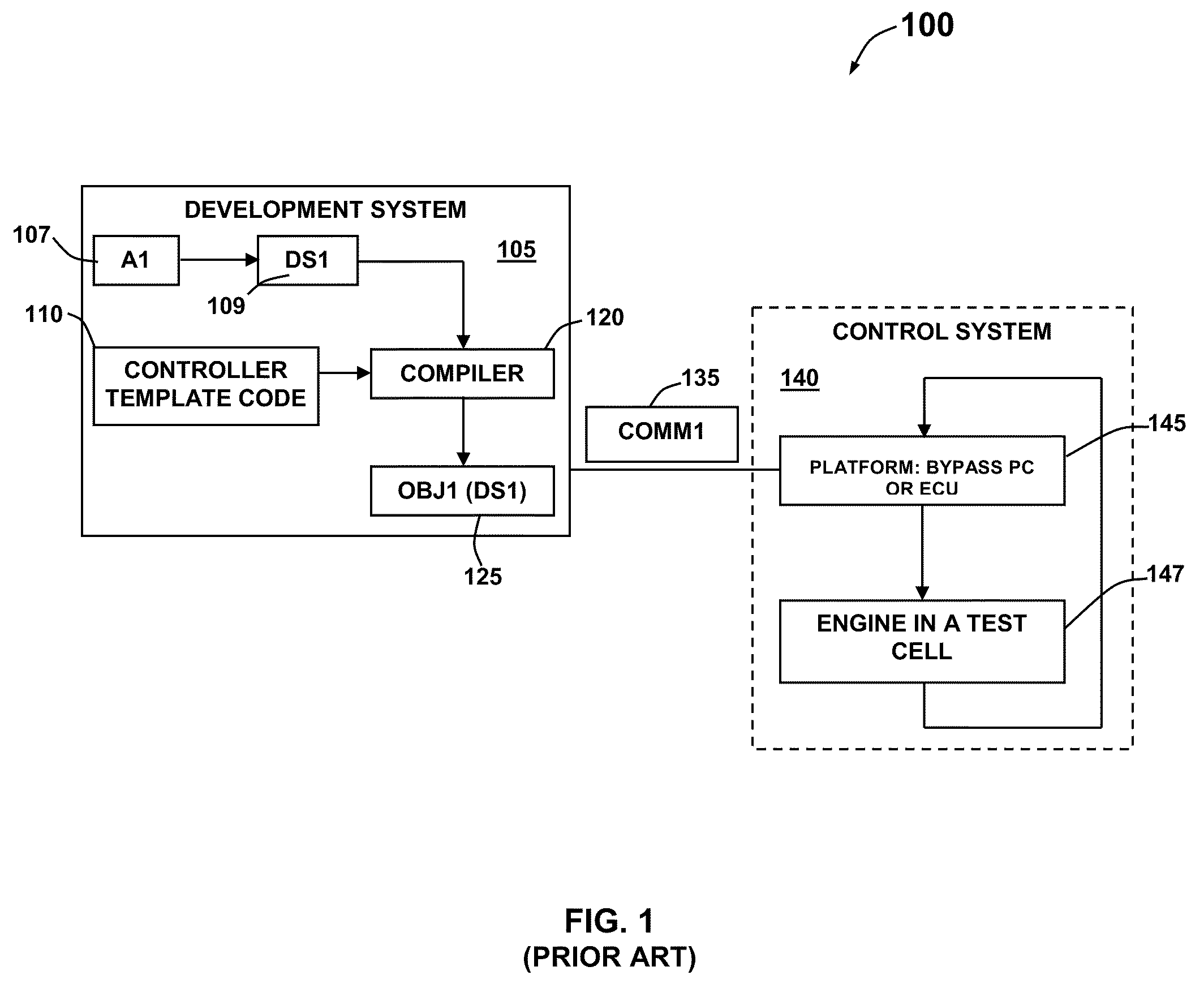
FIG. 1 illustrates a prior art update process diagram for an MPC-based controller or explicit MPC based controller 100 residing on a platform 145 in which tuning parameters of a controller (not shown in FIG. 1) are updated. FIG. 1 depicts the use of an application A1 107 associated with the update process for MPC based controller or explicit MPC-based controller 100. The application 107 (A1) can be employed to modify data sets for use in generating a controller data set 109 (DS1) that defines control laws, models, and parameters for the bank of observers. The newly generated data set(s) 109 can be embedded in association with a controller template code 110. The controller template code 110 can be compiled with specific data set(s) 109 via a compiler 120 and the resulting code compiled with data sets 125 may be further fed as input to an ECU (Electronic Control Unit) 145 via a communications channel 135 by terminating the test at an engine associated with an engine test cell 147. The resulting code may be deployed in the context of a software application in the loop and/or actual hardware in the loop testing platforms.
Such a prior art approach provides a fixed structure of the source code and is referred to as a "template"; however, such an approach does not free a practitioner from recompiling the controller code for a controller residing on platform 145 at each change of the tuning parameters or modifications of plant models. This hinders the possibility of tuning the controller residing on platform 145 seamlessly in a manner that the practitioner can take advantage of simultaneously tune parameters and monitor the changed behavior of the closed loop system 140.
Based on the foregoing, it is believed that a need exists for an improved method and system for enabling seamless tuning of controllers such as, for example, an explicit MPC controller or a standard MPC controller. A need also exists for an improved method and system for updating the tuning parameters of controllers without repetitive compilation of the controller code, as described in greater detail herein.
BRIEF SUMMARY
The following summary is provided to facilitate an understanding of some of the innovative features unique to the present invention and is not intended to be a full description. A full appreciation of the various aspects of the embodiments disclosed herein can be gained by taking the entire specification, claims, drawings, and abstract as a whole.
It is, therefore, one aspect of the present invention to provide for an improved method and system for configuring a controller such as, for example, an explicit MPC controller, a MPC based controller, and/or non-MPC based controllers.
It is another aspect of the present invention to provide for an improved method and system for enabling seamless tuning of controllers such as, for example, explicit MPC controllers, a MPC based controllers, and/or non-MPC based controllers.
It is a further aspect of the present invention to provide for an improved method and system for updating the tuning parameters of a controller (e.g., explicit MPC controller, a MPC based controller, non-MPC based controllers, etc.) without repetitive compilation of a controller code.
The aforementioned aspects and other objectives and advantages can now be achieved as described herein. A system and method for updating tuning parameters and data sets associated with a controller without repetitive compilation of a controller code is disclosed. The datasets may be composed of information describing, for example, any of the following: controllers, plant models, tuning parameters, state space or parameter space partitions, etc.
The controller code represents an algorithm associated with the controller and can be compiled separately from one or more data sets indicative of an explicit control law associated with a model predictive controller optimization problem. The algorithm can be implemented in a programming language code suitable for implementation via an embedded platform or any other type of computer platforms. The data sets can be represented in a specified data structure and the variables associated with the data structure can be declared. The variables may be directly or indirectly accessible or visible from the controller template code variable space. A particular amount of memory may be pre-allocated for variables associated with the data structure. Such variables include complete data sets representing at least the control law, but also may include information related to, for example, any of the following: plant models, tuning parameters, state space or parameter space partitions, etc. The variables can be updated independently from changing the compiled code associated with the controller algorithm referring to the variables.
In one embodiment, an offline optimization application enables users to perform weighting tuning of an MPC optimization problem along with executing an offline parametric optimization algorithm and then generating data sets indicative of the explicit control law. In addition, the offline application provides data transfer of generated sets via a communication channel. The offline optimization application avoids the compilation of the controller template by storing the compiled controller template on an OEM (Original Equipment Manufacturer) platform and updating the control law data sets. Note that the term "OEM platform," as utilized herein, refers generally to an embedded platform or any other type of computer platform. A data loader and an additional pre-allocated memory unit can also be included to perform the tuning parameters update without halting the controller operation. The data loader can be utilized to copy the data sets between the memory units. Note that by the terms "memory units" or "memory unit," we consider any type of memory space or any type of pre-allocated memory space.
In another embodiment, the controller can be updated while the controller actively performs online in order to seamlessly update the controller data sets representing the control laws and the observers' data sets utilized for prediction in a MPC algorithm. A pair of controller instances can be implemented with respect to a real time target in order to seamlessly update the observers' data sets and guarantee a flawless transfer of data. The controllers can be switched between the pair of controller instances seamlessly with updated tuning data sets for both the control law and a bank of observers.
The approach described herein enables seamless tuning of a controller such as, for example, an explicit MPC-based controller or a MPC-based controller, via a development phase and a test phase associated with a plant model in an online application. A controller can be implemented such that the coded algorithm is unchanged, despite changes to the tuning parameters and the plant model. Such an approach enables repetitive tuning of the controller without repetitive compilation of the controller code. The compiled code can be downloaded to an ECU (Electronic Control Unit) or any other type of computer platform that communicates electronically with, for example, a rapid prototyping system (or any other OEM computer platform). Such an approach represents a major time saving opportunity in the process of controller synthesis, calibration, and deployment with respect to the target ECU as well as a major time saving opportunity for the process of validation and fine tuning of a final controller design.
BRIEF DESCRIPTION OF THE DRAWINGS
The accompanying figures, in which like reference numerals refer to identical or functionally-similar elements throughout the separate views and which are incorporated in and form a part of the specification, further illustrate the present invention and, together with the detailed description of the invention, serve to explain the principles of the present invention.
FIG. 1 illustrates a prior art process diagram for updating tuning parameters of a controller;
FIG. 2 illustrates a schematic view of a computer system in which the present invention may be embodied;
FIG. 3 illustrates a schematic view of a software system including an operating system, application software, and a user interface for carrying out the present invention;
FIG. 4 illustrates a graphical representation of a network of data-processing systems in which aspects of the present invention may be implemented;
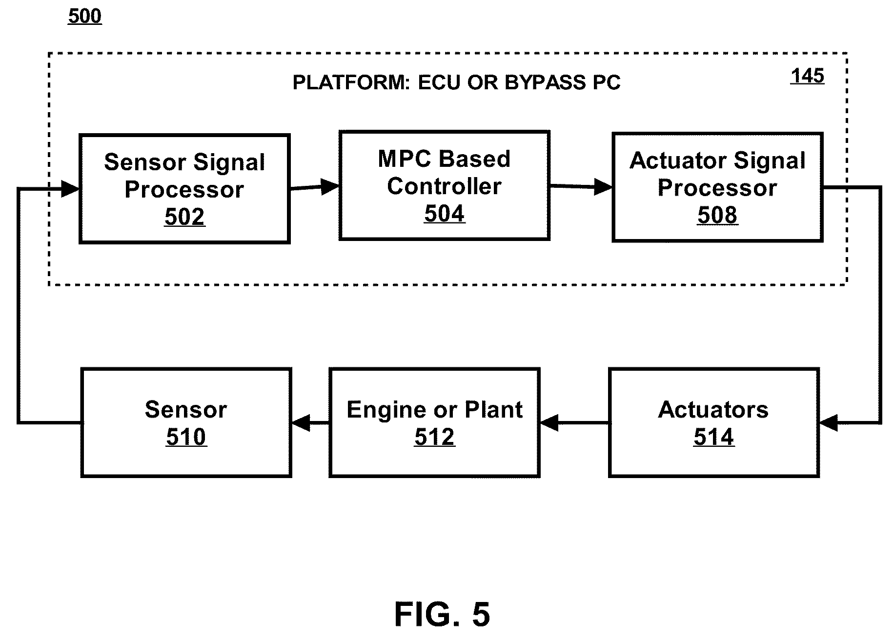
FIG. 5 illustrates a schematic block diagram of a general control system associated with a MPC controller or explicit MPC controller or any other type of controller in accordance with embodiments of the present invention;
FIG. 6 illustrates a process diagram for updating tuning parameters in a controller such as, for example, an explicit MPC controller or a MPC-based controller, in accordance with an embodiment;
FIG. 7 illustrates a high level flow chart of operations illustrating operational steps of a method for updating tuning parameters in a controller such as, for example, an explicit MPC controller or a MPC-based controller, in accordance with an embodiment;
FIG. 8 illustrates a template structure for updating controller without performing recompilation, in accordance with an embodiment;
FIG. 9 illustrates a template structure for updating a controller without stopping the controller operation, in accordance with an embodiment;
FIG. 10 illustrates a possible template structure for updating a controller while the controller is performing on-line, in accordance with an embodiment;
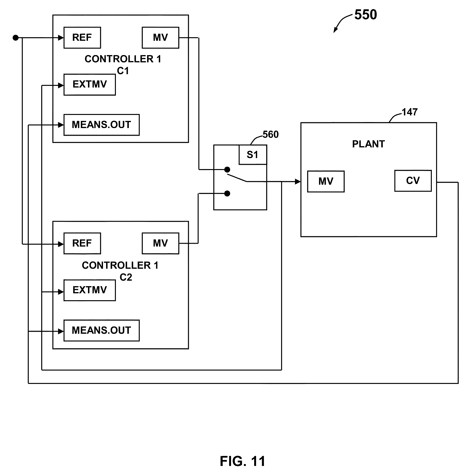
FIG. 11 illustrates a process diagram indicative of the bumpless switching of two (or more) controllers in the closed loop with a plant while actively operating on-line, in accordance with an embodiment; and
FIG. 12 illustrates a functional block diagram illustrating a method for updating tuning parameters in a controller, in accordance with an embodiment.
DETAILED DESCRIPTION
The particular values and configurations discussed in these non-limiting examples can be varied and are cited merely to illustrate at least one embodiment and are not intended to limit the scope thereof.
MPC (Model-based Predictive Control) is a control strategy based on the computation of a series of control actions by solving an optimization problem with respect to specified constraints on plant inputs and outputs and utilizing the knowledge of the plant models. The approach described herein enables repetitive tuning of a controller without repetitive compilation of the controller code. Reference is made generally to the use of MPC-based controllers such as explicit or traditional MPC controllers, but it can be appreciated that the disclosed embodiments may also apply to non-MPC based controllers, depending upon design considerations. The compiled code discussed herein may be downloaded to an ECU (Electronic Control Unit) or any other type of computer platform associated with, for example, a rapid prototyping system or an OEM computer platform, depending upon design considerations.
Note that the disclosed embodiments may be applied to any of a number of computing platforms. For example, the disclosed computer system such as data-process apparatus 150, as shown in FIG. 2, may be adapted for use as a development platform or an embedded platform or system that communicates with a controller platform. Note that as utilized herein the term "controller platform" can refer to any type of computer platform, where a controller resides. These two basic elements can communicate with one another through any type of electronic communications channel (e.g., wired communications, wireless communications, etc.).
The following discussion with respect to FIGS. 2-4 is intended to provide a brief, general description of suitable computing environments in which the disclosed approach may be embodied. Although not required, the method and system herein can be described in the general context of computer-executable instructions, such as program modules, being executed by a single computer.
Generally, program "modules" include routines, programs, objects, components, data structures, etc., that perform particular tasks or implement particular abstract data types. Moreover, those skilled in the art will appreciate that the method and system may be practiced with other computer system configurations, including hand-held devices, multi-processor systems, microprocessor-based or programmable consumer electronics, networked PCs, minicomputers, mainframe computers, and the like.
FIGS. 2-4 are provided as exemplary diagrams of data processing environments in which embodiments of the present invention may be implemented. It should be appreciated that FIGS. 2-4 are only exemplary and are not intended to assert or imply any limitation with regard to the environments in which aspects or embodiments of the present invention may be implemented. Many modifications to the depicted environments may be made without departing from the spirit and scope of the present invention.
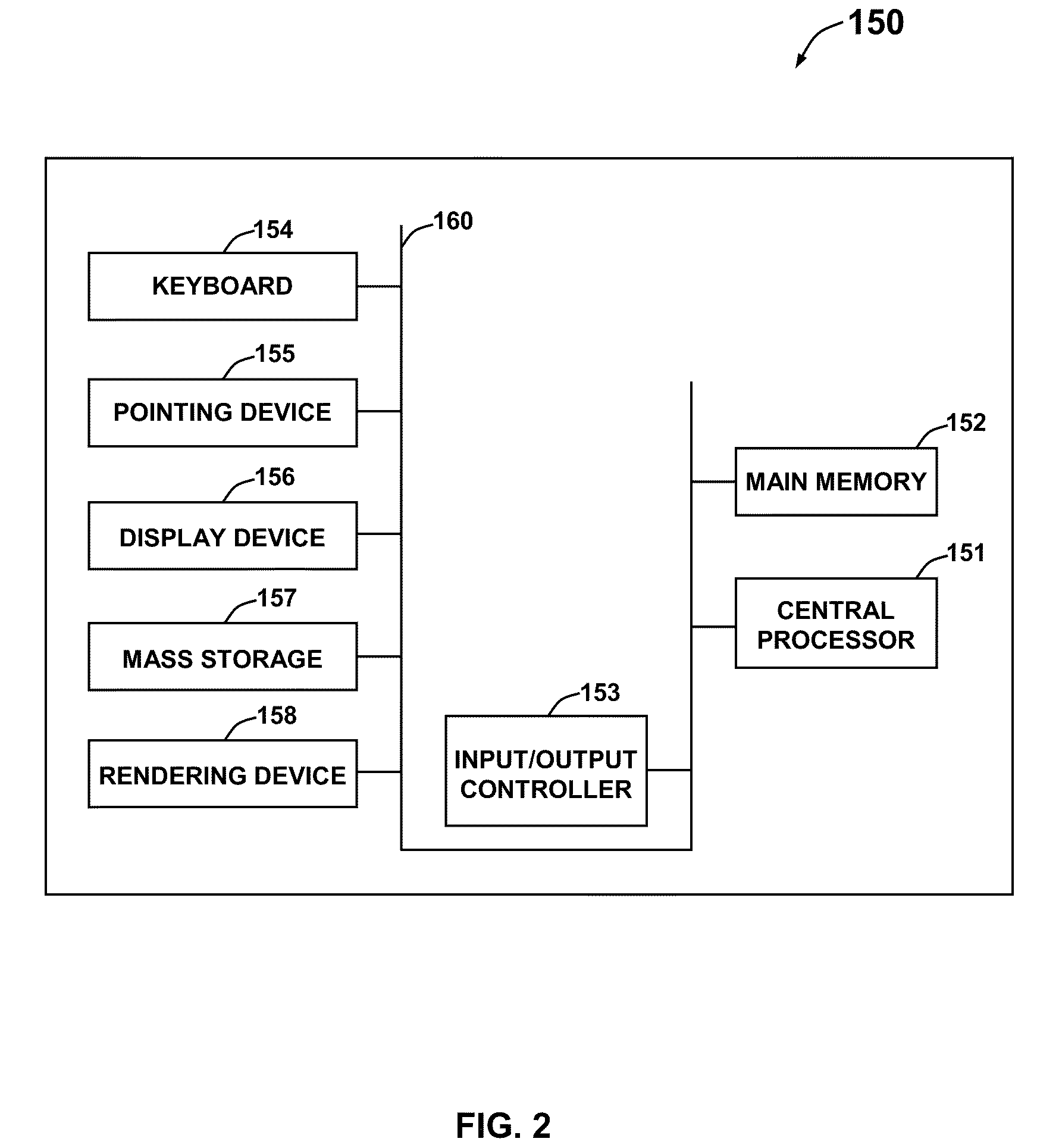
As depicted in FIG. 2, the embodiments may be implemented in the context of a data-processing apparatus 150 comprising a central processor 151, a main memory 152, an input/output controller 153, a keyboard 154, a pointing device 155 (e.g., mouse, track ball, pen device, or the like), a display device 156, and a mass storage 157 (e.g., hard disk). Additional input/output devices, such as a rendering device 158, may be included in the data-processing apparatus 150 as desired. Note that the rendering device 158 may constitute, for example, a printer, a copier, fax machine, scanner, and/or other types of rendering components, depending upon design considerations. As illustrated, the various components of the data-processing apparatus 150 may communicate through a system bus 160 or similar architecture. It can be appreciated that the data-processing apparatus 150 may be in some embodiments, other types of computing devices such as, for example, a mobile computing device such as a Smartphone, a laptop computer, iPhone, etc. In other embodiments, data-processing apparatus 150 may function as a desktop computer, server, and the like, depending upon design considerations.
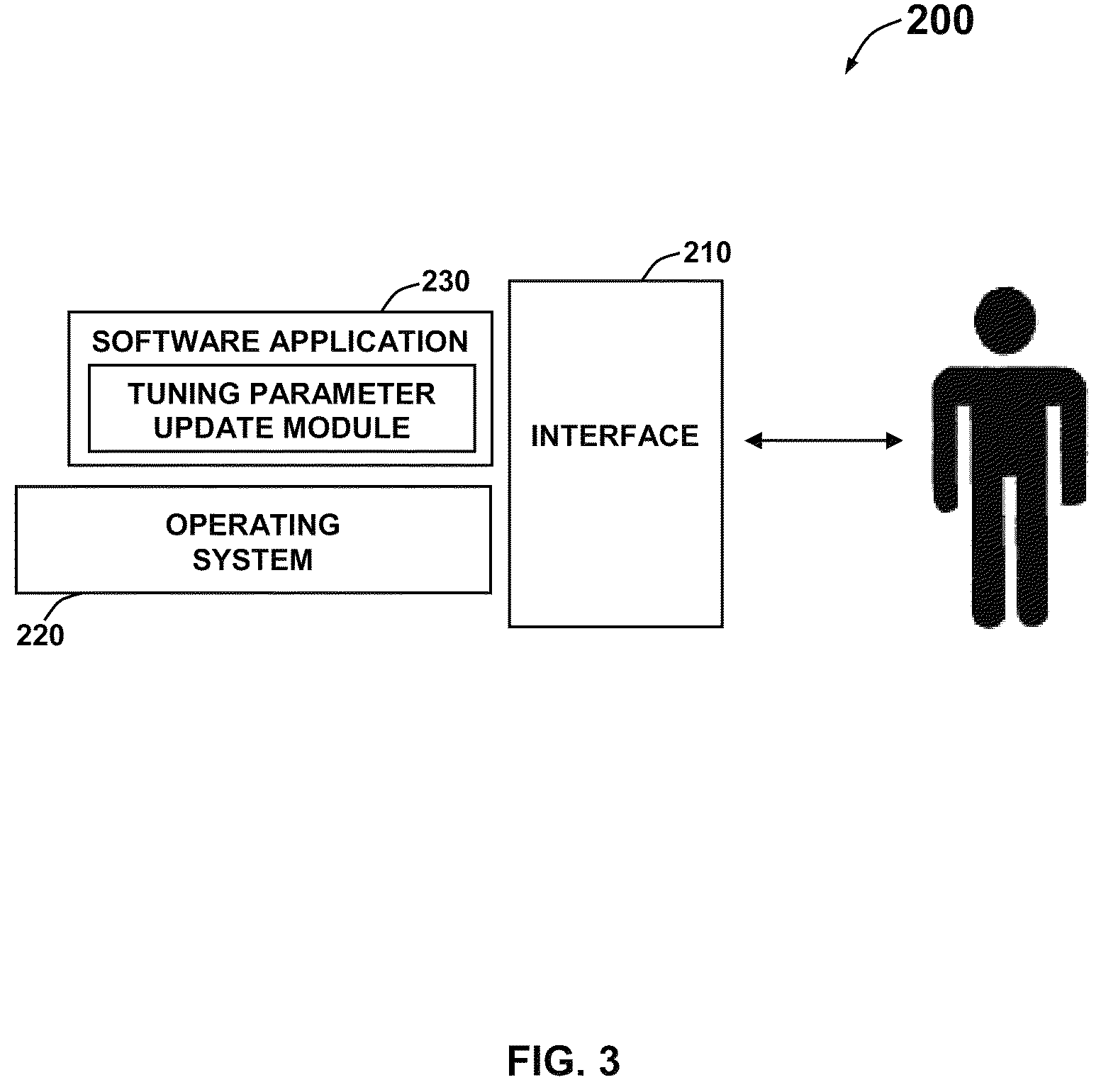
FIG. 3 illustrates a computer software system 200 for directing the operation of the data-processing apparatus 150 depicted in FIG. 2. Software application 230, which is stored in main memory 152 and on mass storage 157, includes a kernel or operating system 220 and a shell or interface 210. One or more application programs, such as application software 230, may be "loaded" (i.e., transferred from mass storage 157 into the main memory 152) for execution by the data-processing apparatus 150. The data-processing apparatus 150 receives user commands and data through user interface 210; these inputs may then be acted upon by the data-processing apparatus 150 in accordance with instructions from operating module 220 and/or application module 230.
Note that the term "module" as utilized herein may refer to a collection of routines and data structures that perform a particular task or implements a particular abstract data type. Modules may be composed of two parts: an interface, which lists the constants, data types, variable, and routines that can be accessed by other modules or routines; and an implementation, which is typically private (accessible only to that module) and which includes source code that actually implements the routines in the module. The term "module" may also simply refer to an application such as a computer program design to assist in the performance of a specific task, such as word processing, accounting, inventory management, etc.
The interface 210, which is preferably a graphical user interface (GUI), also serves to display results, whereupon the user may supply additional inputs or terminate the session. In an embodiment, operating system 220 and interface 210 can be implemented in the context of a "Windows" system. It can be appreciated, of course, that other types of systems are possible. For example, rather than a traditional "Windows" system, other operation systems such as, for example, Linux may also be employed with respect to operating system 220 and interface 210. The tuning parameters update module 230 can be adapted for updating the tuning parameters associated with a controller while actively operating on-line without recompilation. Application module 230, on the other hand, can include instructions such as the various operations described herein with respect to the various components and modules described herein such as, for example, the method 350 depicted in FIG. 7.
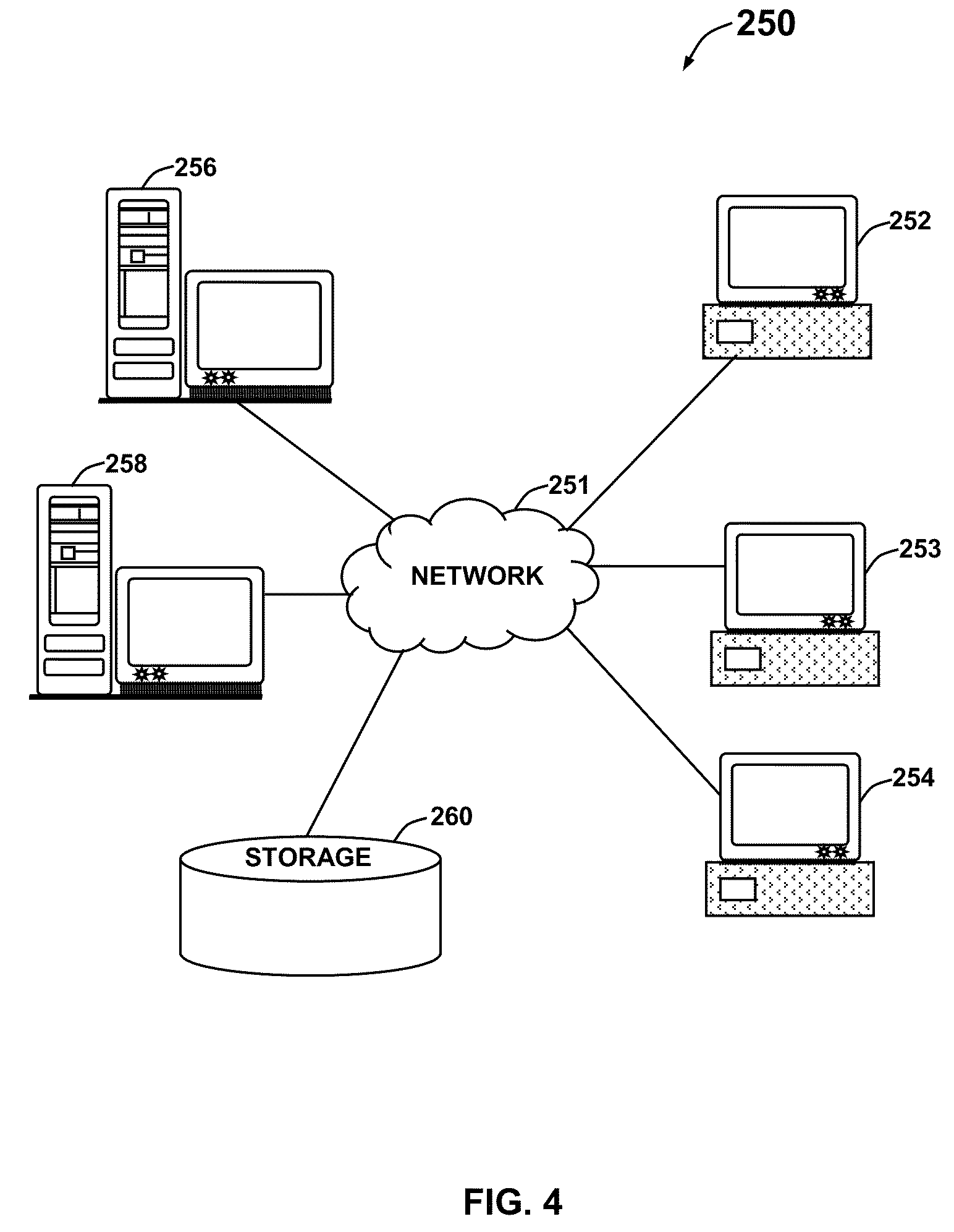
FIG. 4 depicts a graphical representation of a network of data processing system 250 in which aspects of the present invention may be implemented. Network data processing system 250 is a network of computers in which embodiments of the present invention may be implemented. Network data processing system 250 contains network 251, which is the medium used to provide communications links between various devices and computers connected together within network data processing system 250. Network 251 may include connections such as wire, wireless communication links, or fiber optic cables.
In the depicted example, server 256 and server 258 connect to network 251 along with storage unit 260. In addition, clients 252, 253, and 254 connect to network 251. These clients 252, 253, and 254 may be, for example, personal computers or network computers. Data-processing apparatus 150 depicted in FIG. 2 can be, for example, a client such as client 252, 253, and/or 254. Alternatively, data-processing apparatus 150 can be implemented as a server such as servers 256 and/or 258, depending upon design considerations.
In the depicted example, server 258 provides data such as boot files, operating system images, and applications to clients 252, 253, and 254. Clients 252, 253, and 254 are clients to server 258 in this example. Network data processing system 250 may include additional servers, clients, and other devices not shown. Specifically, clients may connect to any member of a network of servers which provide equivalent content.
In the depicted example, network data processing system 250 is the Internet with network 251 representing a worldwide collection of networks and gateways that use the Transmission Control Protocol/Internet Protocol (TCP/IP) suite of protocols to communicate with one another. At the heart of the Internet is a backbone of high-speed data communication lines between major nodes or host computers consisting of thousands of commercial, government, educational, and other computer systems that route data and messages. Of course, network data processing system 250 also may be implemented as a number of different types of networks such as, for example, an intranet, a local area network (LAN), or a wide area network (WAN). FIG. 2 is intended as an example and not as an architectural limitation for different embodiments of the present invention.
The following description is presented with respect to embodiments of the present invention, which can be embodied in the context of a data-processing system such as data-processing apparatus 150, computer software system 200, data processing system 250, and network 251 depicted respectively FIGS. 2-4. The present invention, however, is not limited to any particular application or any particular environment. Instead, those skilled in the art will find that the system and methods of the present invention may be advantageously applied to a variety of system and application software including database management systems, word processors, and the like. Moreover, the present invention may be embodied on a variety of different platforms including Macintosh, UNIX, LINUX, and the like. Therefore, the description of the exemplary embodiments, which follows, is for purposes of illustration and not considered a limitation.
FIG. 5 illustrates a general control system 500 that includes a MPC based controller 504 which resides on a platform 145 (e.g., an ECU, ByPass PC, or any other computer type). Note that by the term "MPC based controller" as utilized herein, we consider both an explicit MPC controller, where a computation of a MPC optimization problem is solved off-line and in the form of an explicit control law; and a MPC based controller, wherein the computation of the MPC optimization problem is performed on-line during each sampling period. The latter type of MPC based controller can also be referred to as a "traditional MPC controller" herein, which is a term widely utilized in the process industry. Note that an explicit MPC controller is more suitable for use with an embedded control application such as control solutions in the automotive industry.
Note that in FIGS. 1-12, identical or similar blocks are generally indicated by identical reference numerals. As depicted in FIG. 5, a sensor signal processor 502 provides data to a MPC based controller 504. The controller 504 in turn provides an output that is then input to actuator signal processor 508. Data from the processor 508 is then provided to one or more actuators 514 whose output is input to an engine/plant 512. Signal output from the engine/plant 512 can be then provided to the sensor 510, which in turn provides sensor signals to the sensor signal processor 502.
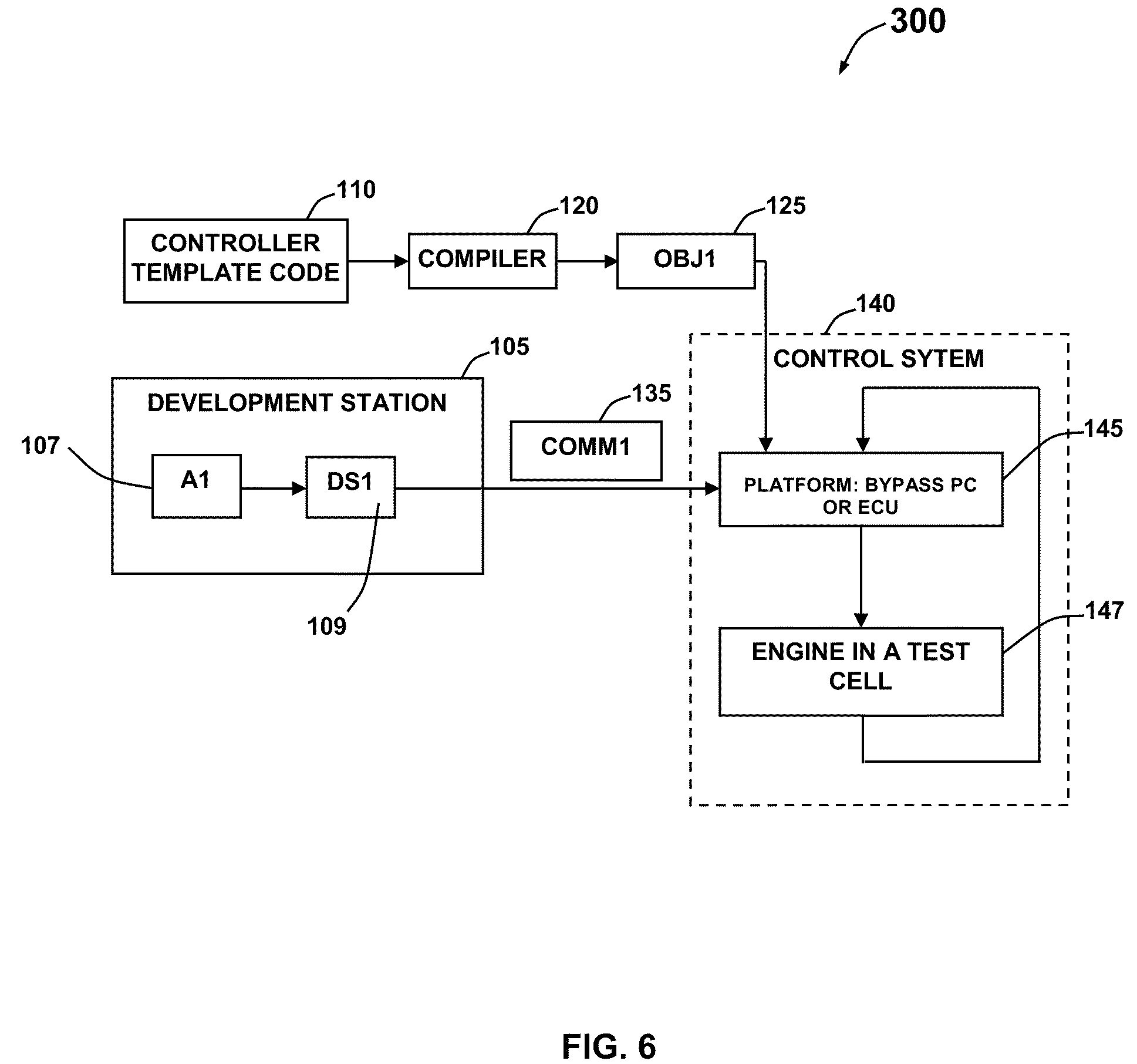
Note that the disclosed approach can be effectively utilized for seamless tuning MPC-based controllers such as the controller 504 (which resides on the platform 145) via a development and a test phase associated with a plant/engine model. A development workstation such as the workstation 105 depicted in FIG. 6 communicates with the controller platform 145. The controller 504 can include an application A1 (see FIG. 6) that represents an application for explicit MPC based controller or MPC based controller 504 tuning and the generation of corresponding data set(s).
Data-processing apparatus 150 depicted in FIG. 2 can be employed, for example, as the development workstation 105. The application A1 107 can be modified in order to generate controller data sets DS1 109 that defines control laws and bank of observer data sets. The data sets DS1 109 can be passed to a platform 145 via a communication channel 135. Further, a controller template code 110 representing algorithm of the controller 504 residing on platform 145 can be compiled via a compiler 120. The controller code 110 representing the algorithm can be compiled separately from the data set DS1 109 representing a solution for a MPC optimization problem. The algorithm can be implemented in a programming language code suitable for implementation, for example, via a rapid prototyping system. The platform 145 may be configured to provide such a function, in certain instances.
The programming language code described herein can be, for example, a C programming language code or another appropriate programming language. It will be apparent to those skilled in the art that a number of language codes may be utilized as desired without departing from the scope and spirit of the disclosed embodiments. The platform 145 may be, for example, an OEM platform, an embedded platform, or a rapid prototyping system (e.g., dSpace, Mathworks RTW, etc). The MPC based controller 504 depicted at FIG. 5 resides on the platform 145. The control system 140 can include platform 145 which can be an ECU or a bypass personal computer where controller 504 resides and which is connected to a test cell 147 with an engine or other type of plant. The data sets DS1 109 can be represented in a specified data structure and the variables associated with the data structures can be declared. For example, the data sets DS1 109 can be specified by "typedef struct" in the C programming language. A certain amount of memory can be pre-allocated for the variables associated with the data structures. Such variables include complete data sets representing the control law. The variables can be updated independently from changing the compiled code associated with the controller algorithm that is referring to the variables.
FIG. 5 thus illustrates a schematic block diagram of a general control system 500 associated with a MPC based controller or an explicit MPC controller 504. The control system 500 can be adapted for use with MPC controller 504 for controlling, for example, an automotive system. The MPC controller 504 can include, for example, a model of the dynamic operation process of an automotive system. The control system 500 can also be configured to include a platform (e.g., an ECU or By-Pass PC) or any other computer type, connected to a plant, for example, or an engine (i.e., and sometimes transmission, emissions after treatment device, brake or other automotive systems and/or components, etc.).
FIG. 6 illustrates a diagram of a process 300 for updating tuning parameters in a controller such as, for example, an explicit MPC controller or a MPC-based controller, in accordance with an embodiment. In general, data form a controller template code is fed to the compiler 120, which in turn produces a compiled code 125 (i.e., OBJ1 in FIG. 6) that is supplied to the control system 140 and specifically, the platform 145. Data from platform 145 can be provided to, for example, an engine in a test cell 147, whose output is then provided as feedback back to the platform 145. The development station 105 discussed herein can additionally provide data and instructions via a communications link 135 (COMM1) to the platform 145. As indicated herein, the development station 105 generally includes an application A1 107 and data set(s) D1 109, which are discussed in greater detail herein. Note that the software application 230 depicted in FIG. 3 is analogous to the application A1 illustrated in FIG. 6. The software application 230 may optionally include a compiler for compiling a controller template (as discussed herein). The controller template code 110, the complier 120, and the compiled code 125 (OBJ1) may also be deployed at the development station 105. In this manner, the compiler could be (but not necessarily) a part of the main off-line application and could additionally reside on the same development station.
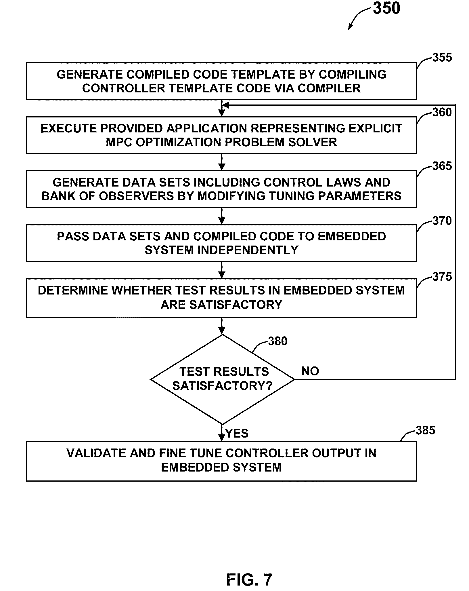
FIG. 7 illustrates a high level flow chart of operations illustrating operational steps of a method 350 for updating tuning parameters in the MPC controller 504 residing on platform 145, in accordance with an embodiment. The MPC controller 504 residing on platform 145 can be implemented such that the coded algorithm is unchanged despite of the changes of the tuning parameters and plant models. Initially, the compiled template 125 can be generated by compiling the controller template code 110 representing algorithm associated with the controller 504 residing on platform 145 via the compiler 120, as depicted at block 355. The compiled code 125 can be further provided to the platform 145 independently. The application A1 representing MPC optimization problem solver in the case of explicit MPC controller or some other tuning algorithm for the case of MPC-based controller can be provided for explicit MPC controller tuning and generating data sets DS1, as illustrated at block 360.
The application A1 can be utilized to generate one or more data sets DS1 representing the solution for the MPC optimization problem by modifying the tuning parameters, as indicated at block 365. Further, the data sets DS1 from the development workstation 105 can be passed to the platform 145 via the communication channel 135, as depicted at block 370. A determination can be made whether the test results for the control system 140 are satisfactory, as indicated at block 375. If the test results are satisfactory as depicted at block 380, the data sets DS1 can be validated and the compiled template 125 from the compiler 120 can be fine tuned, as illustrated at block 385. Else, the process can be continued from block 360. The method 350 described herein can therefore represent a major time saving opportunity in the process of controller synthesis, calibration, and deployment to the platform 145 as well as a major time saving opportunity for the process of validation and fine tuning of the final controller design and control system 140.
In one embodiment, the proposed method 350 can update the controller 504 residing on platform 145 with tuning parameters without performing re-compilation of the controller 504. Such an approach avoids compilation of the controller template by storing the compiled controller template on the platform 145 and updating only control law data sets. In another embodiment, the proposed method 350 can be provided with a data loader 460 and an additional pre-allocated memory unit in order to perform the tuning parameters update without stopping the controller operations. In another embodiment, the method 350 can update the controller 504 while the controller 504 residing on platform 145 is actively performing on-line in order to be able to seamlessly update both the controller data sets DS1 representing the control law and the observers' data sets utilized for prediction in MPC algorithm.
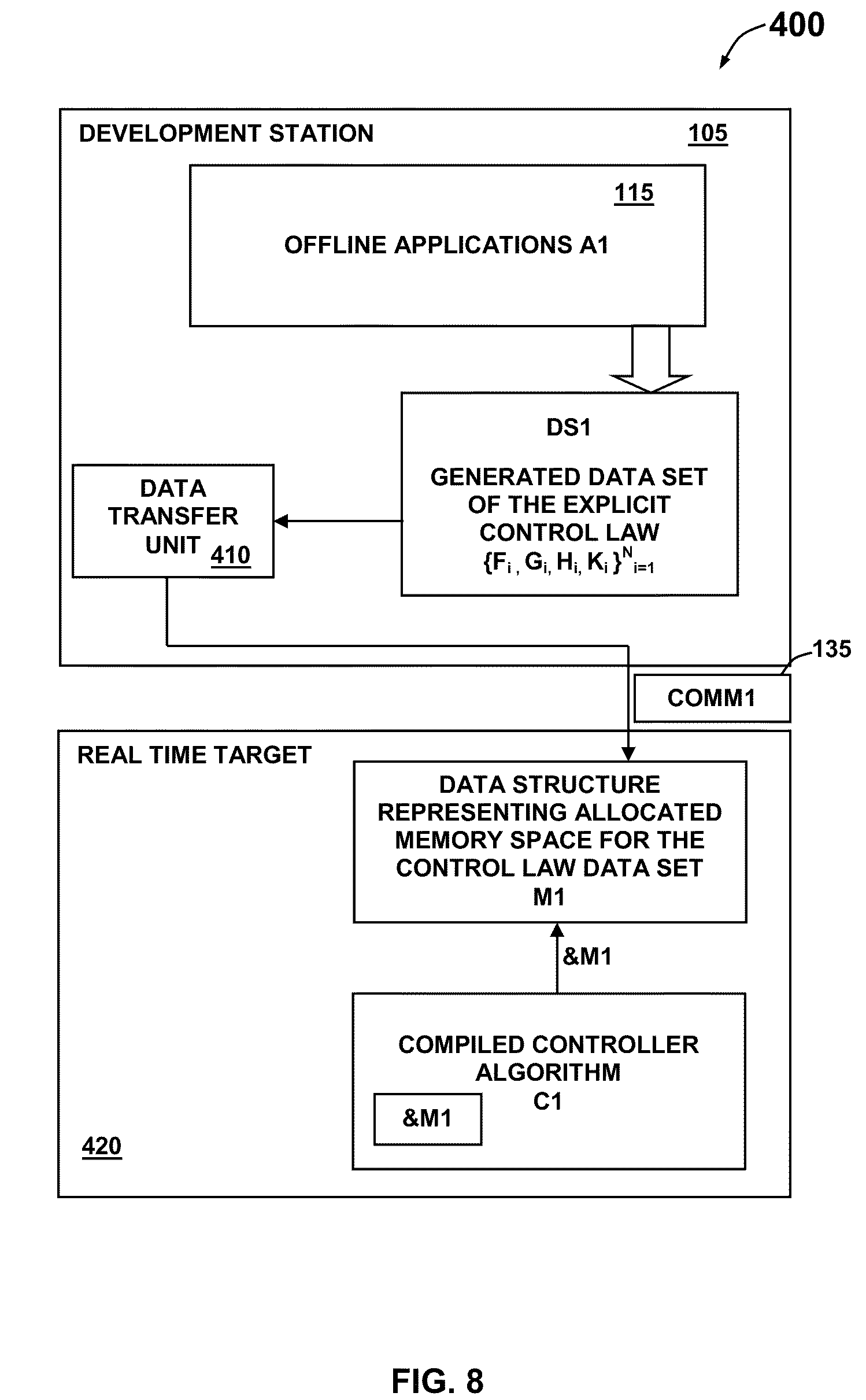
FIG. 8 illustrates a template structure 400 for updating the MPC controller 504 residing on platform 145 without performing recompilation, in accordance with an embodiment. The user associated with an offline application A1 can alter the tuning parameters of the MPC controller 504 as desired. The offline optimization application 115 (i.e., A1 in FIG. 8) permits users of the controller 504 residing on platform 145 to perform weighting tuning associated with the MPC optimization problem, executes offline parametric optimization algorithm, and generates the data set DS1 describing the explicit control law and observer data sets. The data sets DS1 describing the solutions for the MPC optimization problem can be represented as set of matrices {F.sub.i, G.sub.i, H.sub.i, K.sub.i }.sup.N.sub.i=1, wherein the case of explicit MPC solution those matrices define resulting piecewise controller functions as a set of control laws over polyhedral sets. The generated data sets DS1 at the development station 105 can be further transferred to a data transfer unit 410. Further, the operation of the controller C1 can be terminated and the data sets DS1 from the data transfer unit 410 can be transferred to a real time target 420 via the data communication channel 135.
Note that the controller C1 described herein can be a MPC based controller 504 that was generated by the compiled code 125 independently. An appropriate communication can be established between the development computer station 105 and the real time target platform 420. The data sets DS1 that are transferred to the real time target platform 420 can be stored in a memory unit M1 which can be a series of data structures representing allocated memory space for the data sets DS1. Finally, the operations of the controller C1 can be resumed and the compiled code 125 from the controller C1 can be stored into the platform 145 independently. Such an approach avoids compilation of the controller template 110 by storing the compiled controller template 125 on the platform 145 and updating only the control law data sets DS1. However, the approach requires stopping of the controller operation and restart of the controller C1 repeatedly.
FIG. 9 illustrates a template structure 450 for updating the MPC controller 504 residing on platform 145 without stopping the controller operations, in accordance with an embodiment. Again as reminder, in FIGS. 1-11 identical or similar blocks are generally indicated by identical reference numerals. A data loader 460 and an additional pre-allocated memory unit M2 can be included in association with the real time target platform 420 to perform the tuning parameters update without stopping the controller C1. Initially, the control law data sets that are stored in the memory unit M2 can be utilized by the controller C1 via a pointer &M2. The memory unit M2 includes a copy of data structure that represents allocated memory space for the control law data sets. The user associated with the offline application A1 change the tuning parameters as desired and a new set of data DS1 describing the explicit control law and observer data sets can be generated by A1. Thereafter, the data sets DS1 can be transferred to the memory unit M1 via the data transfer unit 410.
The controller C1 freezes its output temporarily and points to the memory unit M1 and starts utilizing the new control law data sets DS1 from the memory unit M1. The data loader 460 copies the new data sets DS1 from the memory unit M1 to the re-allocated memory unit M2. The controller C1 point back to the re-allocated memory unit M2 and continues utilizing the updated control law datasets from the re-allocated memory unit M2. The controller C1 can be seamlessly updated by a convenient manipulation of pointers &M1 and &M2 associated with the memory units M1 and M2. The control law data sets DS1 can be updated without stopping the controller C1. In addition, the observer data sets utilized within the controller C1 can be updated utilizing the template structure described in FIG. 9.
FIG. 10 illustrates a template structure 541 for updating the MPC controller 504 residing on platform 145 while the controller 504 is performing on-line, in accordance with an embodiment. The template structure 541 seamlessly updates the controller data set(s) DS1 representing control laws and the observer data sets without letting the system to "run loose" without having an active controller on-line. The template structure 541 seamlessly updates the controller data set(s) DS1 depicted at block 110, which represents control laws and observers' data sets utilized for prediction operations in the MPC algorithm. A pair of controllers 543 and 545 (respectively, C1 and C2) may be implemented with respect to the real time target platform 420 in order to seamlessly update the observers' data sets and guarantee a flawless transfer of data. Note that the real time target platform 420 represents an example of a software template having a particular structure and is also an example of an implementation of structure, in general. The real time target platform 420 includes elements such as enable transfer module 540, a memory unit (M1-CL1) 549, a memory unit (M2-CL2) 547, copy data module 535, a supervisory module 515, and controllers 543 and 545.
The elements associated with the real time target 420 may form a part of the template structure 541 that is required only once to be deployed on the platform 145.
A signal from the supervisory process 515 to the enable transfer process 540 may be utilized to enable or disable the data transfer from the offline application 115 (A1) to the real time target 420. Additionally, the signal from the supervisory process 515 to the copy data process 535 transfers data from memory 549 (M1-CL1) to memory 547 (M2-CL2), which may each constitute memory units. A permission signal 551 (E1) provides permission to the offline application 115 when it is safe to transfer the data set(s) 110 (DS1) from the development station 105 via the communication channel 135. The status signals 553 and 555 associated with the controllers 543 and 545 indicate the status of the controllers 543 and 545, respectively. The status signals 553 and 555 (respectively, CS1 and CS2) can provide signals such as "inactive", "active", "warming up", "active and able to go inactive", "inactive and able to go active" (i.e. warmed up) signals. CMD1 and CMD2 signals associated respectively with the controllers 543 and 545 represents the commands from the supervisory process 515 to the controllers 543 and 545, respectively. The commands CMD1 and CMD2 from the supervisory process 515 can be "go active", "go inactive", and "use (M1)", "use (M2)", and "warm up" commands.
Initially, the supervisory process 515 provides a "go active" signal to the first controller C1 and activates the first controller C1 while providing a "go inactive" signal to the second controller C2. The active controller C1 utilizes memory unit (M2-CL2) 547 for the data sets DS1. Further, the user associated with the offline application A1 115 can change the tuning parameters and a new data set DS1 describing the explicit control law and observer data sets can be generated by the offline application A1 115. The updated data sets DS1 from the development station 105 can be transferred to the first memory unit (M1-CL1) 549 via the communication channel 135, if the permission signal E1 551 is received.
The supervisory process 515 can instruct the second controller C2 545 to point to the first memory unit (M1-CL1) 549 with a "warm up" signal and waits for the second controller C2 545 to go to "warmed up" state. The supervisory process 515 initiates a sequence of commands after receiving "warmed up" signal from the controller C2 545 and an "active and ready to go inactive" signal from the controller C1 543. At this state, the controller C1 543 receives the "go inactive" signal and C2 545 receives a "go active" signal. Further, the supervisory process 515 transmits a command to the copy data process 535 to copy the updated data sets DS1 from first memory unit (M1-CL1) 549 to the second memory unit (M2-CL2) 547. Also, the controller C2 545 can be pointed towards the second memory unit (M2-CL2) 547. Note that such an approach does not disrupt the work flow of the active controller as both the memory units (M1-CL1) 549 and (M2-CL2) 547 includes the same data.
FIG. 11 illustrates a process diagram depicting operations of a system 550 for the "bumpless" transfer of active controllers in the closed loop with e.g., plant 147, in accordance with an embodiment. Note that the term "bumpless transfer" refers to an existing practice and a solution that can be implemented independent of the procedure described in this section. The proposed approach can be utilized to switch, via switch S1 560, between the first controller C1 and the second controller C2 seamlessly with updated tuning data sets for both control law and bank of observers. For example, consider the active controller C1, depicted at FIG. 9, is controlling the plant while the controller C2 is in "warm up" mode. A controller is in "warm up" mode if the controller follows external MV signals (ExtMV) in order to bring its bank of observers to follow the states of the actual plant. In this way, once the controller C2 is properly "warmed up" it is possible to activate the controller C2, i.e. bring the controller on-line, and de-active the controller C1 without having glitches in the MV signals.
FIG. 12 illustrates a functional process diagram of a method 600 for updating tuning parameters with respect to the MPC controller 504 residing on platform 145, in accordance with an embodiment. Initially, the functional requirements for the desired control system performance can be analyzed and the offline application A1 representing the optimization problems solver in association with the controller 504 can be generated or configured, as depicted at block 610. Further, the steady state calibration can be determined independently of the tuning of the controller 504, as indicated at block 615. Further, based on the functional requirements and the steady state behavior of the plant in the test cell 147 or its dynamic nonlinear model, a functional block of controller 504 residing on platform 145 can be developed, as illustrated at block 620. The functional block can represent the fixed template, data sets DS1 including control law, and observer data sets. The functional block can include optimization solutions for the MPC controller problems. Based on the functional block, the controller 504 can be tuned with optimized parameters and the performance of the control system 140 can be tested, as indicated at blocks 625 and 630. The major time saving using the solutions described here can be expected in steps: 620, 625, 630 and 635.
Further, a determination can be made whether the performance of the plant at test stage is satisfactory, as depicted at block 635. If the test results are not satisfactory, the process can be continued from block 620. Else, a general functional specification can be coded for the functional block, as indicated at block 640. Thereafter, a software specification can be defined for the functional specifications, as indicated at block 645. Utilizing the general functional and software specification, a resulting software code can be coded, as indicated at block 650. The coded software can be tested and a functional testing can also be performed, as illustrated at blocks 655 and 660. Further, the coded software code can be utilized to calibrate and fine tune the controller 504 residing on platform 145, as depicted at block 665.
Note that the steps described herein with respect to block 690 relate generally to software coding operations that can be performed only once. Then, a fixed controller template may be obtained and in every next pass of the process 600, the procedure 690 may be omitted and a direct step from procedure 635 to procedure 665 can be performed.
A determination can be made whether the calibration and tuning parameters associated with the controller 504 on platform 145 are satisfactory, as shown at block 670. If the calibration and tuning parameters are not satisfactory, the process can be continued from block 665. Else, the data sets DS1 can be validated in the platform 145, as described at block 675. The major time saving using the solutions described here can be expected in steps: 665 and 670.
The compiled template code 125 with selected datasets and plant models that provide fine tuned version of the controller 504 can be certified, as indicated at block 680. Finally, the controlled code 125 with selected datasets and plant models providing fine tuned version of controller 504 can be released, as illustrated at block 685. After, a compiled version of the controller is obtained, it is not necessary to recompile the controller again. Such an approach enables repetitive tuning of the controller 504 without repetitive compilation of the controller code 110 and the compiled code 125 can be downloaded to the ECU associated with the platform 145. The one time compilation of the controller code 110 results in time and effort savings and reduces the chances for errors. Such an approach enables seamless transfer of the data sets DS1 describing plant models for the bank of the observers, resulting tuning parameters and/or resulting explicit control laws, and an uninterrupted operation of the controller 504 enabling a bumpless transfer in the operation of control system 500.
It will be appreciated that variations of the above-disclosed and other features and functions, or alternatives thereof, may be desirably combined into many other different systems or applications. For example, the disclosed embodiments may be applied to any type of controller, not merely MPC-based controllers such as traditional or explicit MPC controllers. Also, that various presently unforeseen or unanticipated alternatives, modifications, variations or improvements therein may be subsequently made by those skilled in the art which are also intended to be encompassed by the following claims.
* * * * *
References
-
automotiveworld.com/article/85897-increased-urea-dosing-could-cut-scr-truck-running-costs
-
not2fast.wryday.com/turbo/glossary/turbo-glossary.shtml
-
tai-cwv.com/sbl106.0.html
-
en.wikipedia.org/w/index.php/title=Special:Book&bookcmd=download&collecton-id=641cd1b5da77cc22&writer=rl&return-to=Modelpredictivecontrol
D00000
D00001
D00002
D00003
D00004
D00005
D00006
D00007
D00008
D00009
D00010
D00011
D00012
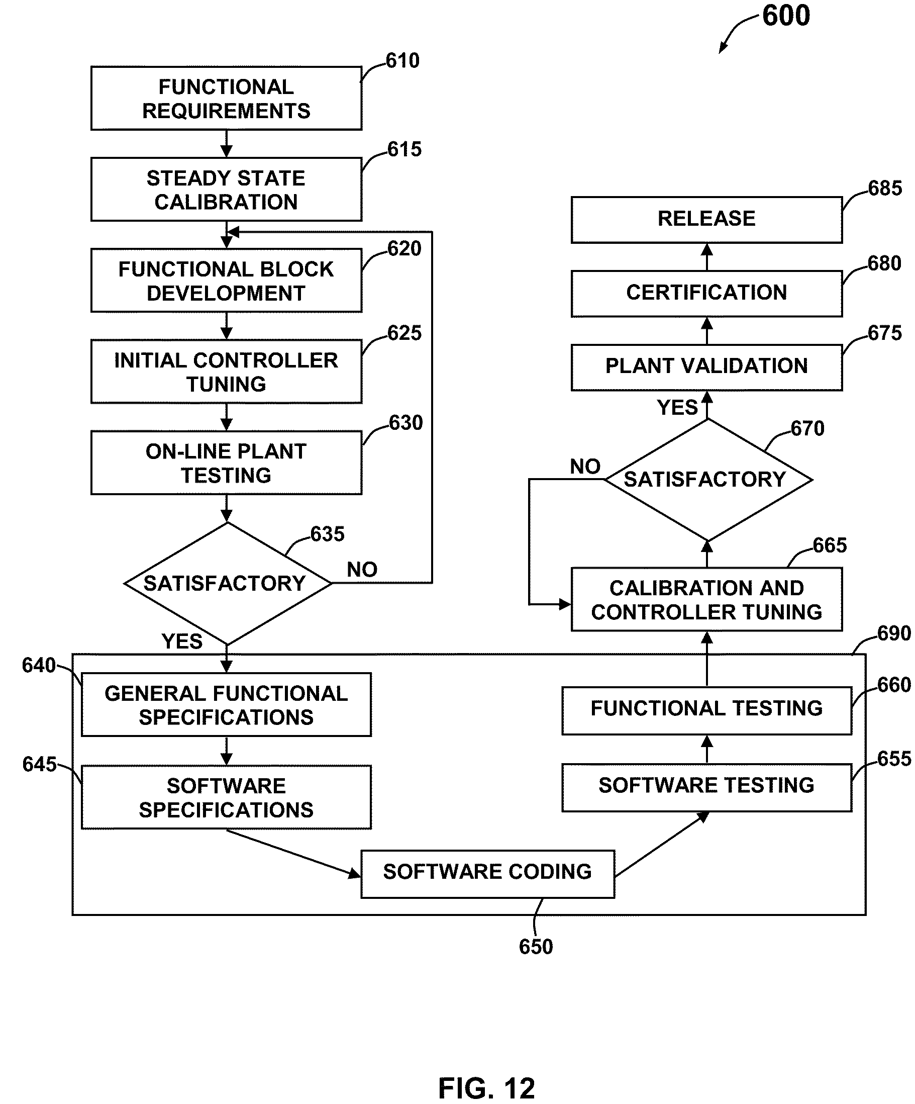
XML
uspto.report is an independent third-party trademark research tool that is not affiliated, endorsed, or sponsored by the United States Patent and Trademark Office (USPTO) or any other governmental organization. The information provided by uspto.report is based on publicly available data at the time of writing and is intended for informational purposes only.
While we strive to provide accurate and up-to-date information, we do not guarantee the accuracy, completeness, reliability, or suitability of the information displayed on this site. The use of this site is at your own risk. Any reliance you place on such information is therefore strictly at your own risk.
All official trademark data, including owner information, should be verified by visiting the official USPTO website at www.uspto.gov. This site is not intended to replace professional legal advice and should not be used as a substitute for consulting with a legal professional who is knowledgeable about trademark law.