Fixation system, an intramedullary fixation assembly and method of use
Tyber , et al. December 30, 2
U.S. patent number 8,920,476 [Application Number 13/646,448] was granted by the patent office on 2014-12-30 for fixation system, an intramedullary fixation assembly and method of use. This patent grant is currently assigned to Extremity Medical, LLC. The grantee listed for this patent is Extremity Medical, LLC. Invention is credited to Chris DiGiovanni, Brian Gerard Donley, Jamy Gannoe, Jeff Tyber.


View All Diagrams
| United States Patent | 8,920,476 |
| Tyber , et al. | December 30, 2014 |
Fixation system, an intramedullary fixation assembly and method of use
Abstract
An intramedullary fixation assembly for bone fusion includes a first member positioned at a proximal end of the intramedullary fixation assembly, where the first member includes a plurality of first and second retaining screws, and a second member positioned at a distal end of the intramedullary fixation assembly, where the second member includes a plurality of third and fourth retaining screws. The first member is slideably coupled to the second member and provides for an interference fit with the second member.
| Inventors: | Tyber; Jeff (Bethlehem, PA), Gannoe; Jamy (West Milford, NJ), DiGiovanni; Chris (Barrington, RI), Donley; Brian Gerard (Solon, OH) | ||||||||||
|---|---|---|---|---|---|---|---|---|---|---|---|
| Applicant: |
|
||||||||||
| Assignee: | Extremity Medical, LLC
(Parsippany, NJ) |
||||||||||
| Family ID: | 44368138 | ||||||||||
| Appl. No.: | 13/646,448 | ||||||||||
| Filed: | October 5, 2012 |
Prior Publication Data
| Document Identifier | Publication Date | |
|---|---|---|
| US 20130053848 A1 | Feb 28, 2013 | |
Related U.S. Patent Documents
| Application Number | Filing Date | Patent Number | Issue Date | ||
|---|---|---|---|---|---|
| 12658699 | Feb 11, 2010 | 8313487 | |||
| 12460069 | Jul 13, 2009 | 8328806 | |||
| 12456808 | Jun 23, 2009 | 8303589 | |||
| 61132932 | Jun 24, 2008 | ||||
| Current U.S. Class: | 606/279; 606/304; 606/86R |
| Current CPC Class: | A61B 17/8625 (20130101); A61B 17/7225 (20130101); A61B 17/7241 (20130101); A61B 17/1775 (20161101); A61B 17/7291 (20130101); A61B 17/1717 (20130101); A61B 17/8605 (20130101); A61F 2002/4238 (20130101); A61F 2002/4233 (20130101); A61B 2017/565 (20130101) |
| Current International Class: | A61B 17/88 (20060101) |
| Field of Search: | ;606/64,80,86R,96,279,304 |
References Cited [Referenced By]
U.S. Patent Documents
| 928997 | July 1909 | Muller |
| 2398220 | April 1946 | Gelpcke |
| 2580821 | January 1952 | Nicola |
| 3019686 | February 1962 | Behrle |
| 3200694 | August 1965 | Rapata |
| 3411398 | November 1968 | Blakeley |
| 3474537 | October 1969 | Christensen |
| 3924276 | December 1975 | Eaton |
| 4152533 | May 1979 | Gazda |
| 4381770 | May 1983 | Neufeld |
| 4465065 | August 1984 | Gotfried |
| 4760843 | August 1988 | Fischer |
| 4795294 | January 1989 | Takada |
| 4854797 | August 1989 | Gourd |
| 4930963 | June 1990 | Rockenfeller |
| 4940467 | July 1990 | Tronzo |
| 4947502 | August 1990 | Engelhardt |
| 4987714 | January 1991 | Lemke |
| 5084050 | January 1992 | Draenert |
| 5112333 | May 1992 | Fixel |
| 5163940 | November 1992 | Bourque |
| 5209753 | May 1993 | Biedermann |
| 5350380 | September 1994 | Goble |
| 5403321 | April 1995 | DiMarco |
| 5456267 | October 1995 | Stark |
| 5478341 | December 1995 | Cook |
| 5501557 | March 1996 | Wakai |
| 5505731 | April 1996 | Tornier |
| 5531748 | July 1996 | de la Caffiniere |
| 5540694 | July 1996 | DeCarlo, Jr. |
| 5573538 | November 1996 | Laboureau |
| 5601550 | February 1997 | Esser |
| 5613971 | March 1997 | Lower |
| 5620449 | April 1997 | Faccioli |
| 5702470 | December 1997 | Menon |
| 5718705 | February 1998 | Sammarco |
| 5718706 | February 1998 | Roger |
| 5741266 | April 1998 | Moran |
| 5766221 | June 1998 | Benderev |
| 5779704 | July 1998 | Kim |
| 5857816 | January 1999 | Assmundson |
| 5865559 | February 1999 | Yang |
| 5888203 | March 1999 | Goldberg |
| 5891150 | April 1999 | Chan |
| 5968050 | October 1999 | Torrie |
| 5984681 | November 1999 | Huang |
| 5997541 | December 1999 | Schenk |
| D420132 | February 2000 | Bucholz |
| 6019761 | February 2000 | Gustilo |
| 6030162 | February 2000 | Huebner |
| 6048343 | April 2000 | Mathis |
| 6106528 | August 2000 | Durham |
| 6120511 | September 2000 | Chan |
| 6123709 | September 2000 | Jones |
| 6123711 | September 2000 | Winters |
| 6126661 | October 2000 | Faccioli |
| 6168595 | January 2001 | Durham |
| 6168597 | January 2001 | Biedermann |
| 6174119 | January 2001 | Orr |
| 6214007 | April 2001 | Anderson |
| 6214012 | April 2001 | Karpman |
| 6221074 | April 2001 | Cole |
| 6235031 | May 2001 | Hodgeman |
| 6247883 | June 2001 | Monserratt |
| 6254605 | July 2001 | Howell |
| 6254606 | July 2001 | Carney |
| 6261039 | July 2001 | Reed |
| 6261290 | July 2001 | Friedl |
| 6270499 | August 2001 | Leu |
| 6280442 | August 2001 | Barker |
| 6287313 | September 2001 | Sasso |
| 6379362 | April 2002 | Birk |
| 6402753 | June 2002 | Cole |
| 6402757 | June 2002 | Moore |
| 6423064 | July 2002 | Kluger |
| 6435788 | August 2002 | Reed |
| 6443954 | September 2002 | Bramlet |
| 6458134 | October 2002 | Songer |
| 6517541 | February 2003 | Sesic |
| 6527775 | March 2003 | Warburton |
| 6562046 | May 2003 | Sasso |
| 6569165 | May 2003 | Wahl |
| 6579293 | June 2003 | Chandran |
| 6589245 | July 2003 | Weiler |
| 6596008 | July 2003 | Kambin |
| 6626916 | September 2003 | Yeung |
| 6629976 | October 2003 | Gnos |
| 6632057 | October 2003 | Fauchet |
| 6634844 | October 2003 | Huber |
| 6648889 | November 2003 | Bramlet |
| 6669700 | December 2003 | Farris |
| 6679888 | January 2004 | Green |
| 6685706 | February 2004 | Padget |
| 6692496 | February 2004 | Wardlaw |
| 6692503 | February 2004 | Foley |
| 6695844 | February 2004 | Bramlet |
| 6709436 | March 2004 | Hover |
| 6712849 | March 2004 | Re |
| 6743018 | June 2004 | Morrow |
| 6778861 | August 2004 | Liebrecht |
| 6793659 | September 2004 | Putnam |
| 6808527 | October 2004 | Lower |
| 6849093 | February 2005 | Michelson |
| 6875216 | April 2005 | Wolf |
| 6908271 | June 2005 | Breslin |
| 6951538 | October 2005 | Ritland |
| 6951561 | October 2005 | Warren |
| 6981974 | January 2006 | Berger |
| 7018380 | March 2006 | Cole |
| 7033398 | April 2006 | Graham |
| 7037309 | May 2006 | Weil |
| 7041104 | May 2006 | Cole |
| 7063724 | June 2006 | Re |
| 7074221 | July 2006 | Michelson |
| 7144399 | December 2006 | Hayes |
| 7160302 | January 2007 | Warburton |
| 7175632 | February 2007 | Singhatat |
| 7229448 | June 2007 | Goble |
| 7232442 | June 2007 | Sohngen |
| 7247156 | July 2007 | Ekholm |
| 7267678 | September 2007 | Medoff |
| 7326248 | February 2008 | Michaelson |
| 7331962 | February 2008 | Branemark |
| 7341588 | March 2008 | Swanson |
| 7344538 | March 2008 | Myerson |
| 7410488 | August 2008 | Janna |
| 7524326 | April 2009 | Dierks |
| 7527627 | May 2009 | Ferrante |
| 7582107 | September 2009 | Trail |
| 7588577 | September 2009 | Fencl |
| 7591819 | September 2009 | Zander |
| 7601153 | October 2009 | Shinjo |
| 7608097 | October 2009 | Kyle |
| 7632272 | December 2009 | Munro |
| 7655009 | February 2010 | Grusin |
| 7666212 | February 2010 | Pathak |
| 7670340 | March 2010 | Brivio |
| 7713271 | May 2010 | Warburton |
| 7717947 | May 2010 | Wilberg |
| 7731721 | June 2010 | Rathbun |
| 7731738 | June 2010 | Jackson |
| 7763021 | July 2010 | Cole |
| 7763022 | July 2010 | Speitling |
| 7763023 | July 2010 | Gotfried |
| 7771428 | August 2010 | Siravo |
| 7785326 | August 2010 | Green |
| 7794483 | September 2010 | Capanni |
| 7799061 | September 2010 | Kay |
| 7815646 | October 2010 | Hart |
| 7842036 | November 2010 | Phillips |
| 7867231 | January 2011 | Cole |
| 7892234 | February 2011 | Schlienger |
| 7892264 | February 2011 | Sanders |
| 7909825 | March 2011 | Saravia |
| 7914532 | March 2011 | Shaver |
| 7918853 | April 2011 | Watanabe |
| 7922748 | April 2011 | Hoffman |
| 7927340 | April 2011 | Hart |
| 7938848 | May 2011 | Sweeney |
| 7947043 | May 2011 | Mutchler |
| 8034056 | October 2011 | Fencl |
| 8034082 | October 2011 | Lee |
| 8057476 | November 2011 | Ekholm |
| 8092453 | January 2012 | Warburton |
| 8100910 | January 2012 | Warburton |
| 8100946 | January 2012 | Strausbaugh |
| 8206424 | June 2012 | Bidermann |
| 8303589 | November 2012 | Tyber et al. |
| 8313487 | November 2012 | Tyber et al. |
| 8328806 | December 2012 | Tyber et al. |
| 8747480 | June 2014 | Cachia |
| 8771323 | July 2014 | Dehnad et al. |
| 2001/0021852 | September 2001 | Chappius |
| 2002/0032445 | March 2002 | Fujiwara |
| 2002/0052605 | May 2002 | Grooms |
| 2002/0128712 | September 2002 | Michelson |
| 2002/0143333 | October 2002 | von Hoffmann |
| 2002/0169453 | November 2002 | Berger |
| 2002/0197134 | December 2002 | Huber |
| 2003/0028193 | February 2003 | Weil |
| 2003/0060827 | March 2003 | Coughln |
| 2003/0065391 | April 2003 | Re |
| 2003/0083667 | May 2003 | Ralph |
| 2003/0147716 | August 2003 | Nagawa |
| 2003/0158555 | August 2003 | Sanders |
| 2003/0229346 | December 2003 | Orbie |
| 2004/0006345 | January 2004 | Vlahos |
| 2004/0082959 | April 2004 | Hayes |
| 2004/0097945 | May 2004 | Wolf |
| 2004/0172031 | September 2004 | Rubecamp |
| 2004/0181234 | September 2004 | McDevitt |
| 2004/0193162 | September 2004 | Bramlet |
| 2004/0220570 | November 2004 | Frigg |
| 2005/0015092 | January 2005 | Rathbun |
| 2005/0069397 | March 2005 | Shavit |
| 2005/0107791 | May 2005 | Manderson |
| 2005/0125070 | June 2005 | Reiley |
| 2005/0149030 | July 2005 | Serhan |
| 2005/0171544 | August 2005 | Falkner |
| 2005/0171546 | August 2005 | Wolf |
| 2005/0187636 | August 2005 | Graham |
| 2005/0192580 | September 2005 | Dalton |
| 2005/0197711 | September 2005 | Cachia |
| 2005/0229433 | October 2005 | Cachia |
| 2005/0240190 | October 2005 | Gall |
| 2005/0251147 | November 2005 | Novak |
| 2005/0273101 | December 2005 | Schumacher |
| 2005/0277940 | December 2005 | Neff |
| 2005/0283159 | December 2005 | Amara |
| 2006/0009774 | January 2006 | Goble |
| 2006/0009846 | January 2006 | Trieu |
| 2006/0015101 | January 2006 | Warburton |
| 2006/0052787 | March 2006 | Re |
| 2006/0095039 | May 2006 | Mutchler |
| 2006/0122600 | June 2006 | Cole |
| 2006/0122612 | June 2006 | Justin |
| 2006/0142770 | June 2006 | Capanni |
| 2006/0149244 | July 2006 | Amrein |
| 2006/0173461 | August 2006 | Kay |
| 2006/0189991 | August 2006 | Bickley |
| 2006/0200141 | September 2006 | Janna |
| 2006/0200143 | September 2006 | Warburton |
| 2006/0200144 | September 2006 | Warburton |
| 2006/0200160 | September 2006 | Border |
| 2006/0206044 | September 2006 | Simon |
| 2006/0229606 | October 2006 | Clement et al. |
| 2006/0235393 | October 2006 | Bono et al. |
| 2006/0235396 | October 2006 | Sanders |
| 2006/0241596 | October 2006 | Rezach |
| 2006/0241608 | October 2006 | Myerson |
| 2006/0241777 | October 2006 | Partin |
| 2006/0247624 | November 2006 | Banouskou et al. |
| 2006/0264954 | November 2006 | Sweeney, II |
| 2006/0271047 | November 2006 | Jackson |
| 2006/0282074 | December 2006 | Renaud et al. |
| 2007/0021839 | January 2007 | Lowe |
| 2007/0038306 | February 2007 | O'Gara |
| 2007/0055286 | March 2007 | Ralph |
| 2007/0066977 | March 2007 | Assell |
| 2007/0073290 | March 2007 | Boehm, Jr. |
| 2007/0093841 | April 2007 | Hoogland |
| 2007/0112432 | May 2007 | Reiley |
| 2007/0162028 | July 2007 | Jackson |
| 2007/0173835 | July 2007 | Medoff |
| 2007/0233114 | October 2007 | Bouman |
| 2007/0270848 | November 2007 | Lin |
| 2007/0270855 | November 2007 | Partin |
| 2008/0065224 | March 2008 | Reigstad |
| 2008/0091203 | April 2008 | Warburton |
| 2008/0154271 | June 2008 | Berberich |
| 2008/0167688 | July 2008 | Fauth et al. |
| 2008/0183215 | July 2008 | Altarac et al. |
| 2008/0200989 | August 2008 | Cachia |
| 2008/0208261 | August 2008 | Medoff |
| 2008/0221623 | September 2008 | Gooch |
| 2008/0269908 | October 2008 | Warburton |
| 2008/0279654 | November 2008 | Deschamps |
| 2008/0287998 | November 2008 | Doubler et al. |
| 2008/0294164 | November 2008 | Frank |
| 2008/0306487 | December 2008 | Hart |
| 2008/0306537 | December 2008 | Culbert |
| 2009/0018542 | January 2009 | Saravia |
| 2009/0048600 | February 2009 | Matityahu |
| 2009/0062797 | March 2009 | Huebner |
| 2009/0082874 | March 2009 | Cachia |
| 2009/0088767 | April 2009 | Leyden |
| 2009/0088804 | April 2009 | Kyle |
| 2009/0088806 | April 2009 | Leyden |
| 2009/0093813 | April 2009 | Elghazaly |
| 2009/0093849 | April 2009 | Grabowski |
| 2009/0093851 | April 2009 | Osman |
| 2009/0099571 | April 2009 | Cresina |
| 2009/0149857 | June 2009 | Culbert |
| 2009/0157077 | June 2009 | Larsen |
| 2009/0157078 | June 2009 | Mikol |
| 2009/0157079 | June 2009 | Warburton |
| 2009/0157080 | June 2009 | Warburton |
| 2009/0177203 | July 2009 | Reiley |
| 2009/0198289 | August 2009 | Manderson |
| 2009/0209961 | August 2009 | Ferrante |
| 2009/0240252 | September 2009 | Chang |
| 2009/0248025 | October 2009 | Haidukewych |
| 2009/0264885 | October 2009 | Grant |
| 2009/0281580 | November 2009 | Emannuel |
| 2009/0292292 | November 2009 | Fencl |
| 2009/0306666 | December 2009 | Czartoski |
| 2009/0326534 | December 2009 | Yamazaki |
| 2010/0023011 | January 2010 | Nakamura |
| 2010/0023064 | January 2010 | Brunger |
| 2010/0030280 | February 2010 | Jackson |
| 2010/0042164 | February 2010 | Lee |
| 2010/0042167 | February 2010 | Nebosky |
| 2010/0057141 | March 2010 | Abdelgany |
| 2010/0069970 | March 2010 | Lewis |
| 2010/0076499 | March 2010 | McNamara |
| 2010/0121324 | May 2010 | Tyber et al. |
| 2010/0121325 | May 2010 | Tyber |
| 2010/0174284 | July 2010 | Schwammberger |
| 2010/0179551 | July 2010 | Keller |
| 2010/0228353 | September 2010 | Cachia |
| 2010/0234846 | September 2010 | Eglseder |
| 2010/0256638 | October 2010 | Tyber |
| 2010/0256639 | October 2010 | Tyber |
| 2010/0312279 | December 2010 | Gephart |
| 2010/0324556 | December 2010 | Tyber et al. |
| 2011/0004255 | January 2011 | Weiner |
| 2011/0022066 | January 2011 | Sevrain |
| 2011/0046681 | February 2011 | Prandi |
| 2011/0060337 | March 2011 | Ferrante |
| 2011/0118739 | May 2011 | Tyber et al. |
| 2011/0125153 | May 2011 | Tyber et al. |
| 2011/0137313 | June 2011 | Jensen |
| 2011/0144645 | June 2011 | Saravia |
| 2011/0160729 | June 2011 | Overes |
| 2011/0218580 | September 2011 | Schwager |
| 2011/0230884 | September 2011 | Mantzaris et al. |
| 2011/0282398 | November 2011 | Overes |
| 2011/0301651 | December 2011 | Kirschman |
| 2011/0307018 | December 2011 | Zucherman et al. |
| 2011/0313469 | December 2011 | McCombs et al. |
| 2012/0004690 | January 2012 | Gonzalez-Hernandez |
| 2012/0010669 | January 2012 | O'Neil |
| 2012/0016424 | January 2012 | Kave |
| 2012/0022603 | January 2012 | Kirschman |
| 2012/0095516 | April 2012 | Dikeman |
| 2012/0109213 | May 2012 | Appenzeller |
| 2012/0197254 | August 2012 | Wolfe et al. |
| 2012/0271359 | October 2012 | Stevenson et al. |
| 2012/0277800 | November 2012 | Jackson |
| 2013/0006306 | January 2013 | Saidha et al. |
| 2013/0030434 | January 2013 | Tyber et al. |
| 2013/0046345 | February 2013 | Jones et al. |
| 2013/0131821 | May 2013 | Cachia |
| 2013/0144204 | June 2013 | Dehnad et al. |
| 2013/0172889 | July 2013 | Tyber et al. |
| 2013/0184759 | July 2013 | Rinehart et al. |
| 2013/0296862 | November 2013 | Brigido |
| 2013/0325077 | December 2013 | Champagne et al. |
| 2013/0345754 | December 2013 | Doubler et al. |
| 2014/0114358 | April 2014 | Brumfield |
| 2006116164 | Nov 2006 | WO | |||
| 2007131287 | Nov 2007 | WO | |||
| 2009120852 | Oct 2009 | WO | |||
Assistant Examiner: Bray; Stuart S
Attorney, Agent or Firm: Ward & Zinna, LLC
Parent Case Text
CROSS-REFERENCE TO RELATED APPLICATIONS
This is a division of Non-Provisional Application Serial No. 12/658,699, filed Feb. 11, 2010, which is a continuation-in-part application of Non-Provisional application Ser. No. 12/460,069, filed Jul. 13, 2009, which is a continuation-in-part of Non-Provisional application Ser. No. 12/456,808, filed Jun. 23, 2009, which claims the benefit of Provisional Application Ser. No. 61,132,932, filed Jun. 24, 2008, the entire contents of the entire chain of applications are herein incorporated by reference.
Claims
The invention claimed is:
1. A method for bone fusion in an extremity, comprising: providing an intramedullary fixation assembly, wherein the intramedullary fixation assembly further comprises: a proximal member positioned at a proximal end of the intramedullary fixation assembly, wherein the proximal member extends from a first end to a second end and comprises an elongated body and first and second retaining screws; and a distal member positioned at a distal end of the intramedullary fixation assembly, wherein the distal member extends from a first end to a second end and comprises third and fourth retaining screws, a first aperture at the first end of the distal member diametrically opposed to the second end of the distal member, and a bore extending from the first aperture to an exterior surface on the distal member, wherein the proximal member is configured for coupling to the distal member and provides for an interference fit with the distal member; forming a first medullary canal in a first bone; forming a second medullary canal in a second bone; inserting the distal member into the first medullary canal; aligning the distal member and inserting the third and fourth retaining screws into the first bone and into the distal member; inserting the proximal member into and through the bore of the distal member; aligning the proximal member and inserting the proximal member into the second medullary canal; and inserting the first and second retaining screws into the second bone and into the proximal member, thereby fusing the first bone to the second bone.
2. The method of claim 1, wherein the distal member includes a second aperature longitudinally coextensive with a length of the distal member.
3. The method of claim 2, wherein the second aperture emanates from the bore.
4. The method of claim 3, wherein the bore is aligned along a bore axis, wherein the distal member is aligned along a longitudinal axis, and wherein the bore axis forms a predetermined angle with the longitudinal axis of the distal member.
5. The method of claim 4, wherein the predetermined angle determines an angle for bone restoration.
6. The method of claim 3, wherein the proximal member is inserted into the bore of the distal member until the first end of the proximal member resides within the bore.
7. The method of claim 3, wherein the bore is tapered.
8. The method of claim 2, wherein the second aperature is provided to receive a complementary shaped end of an instrument.
9. The method of claim 2, wherein the second aperture has a hexagonal shaped, a star shaped, or a square shaped opening.
10. The method of claim 1, wherein the elongated body of the proximal member includes a first circular end and a second tapered end.
11. The method of claim 1, wherein the proximal member comprises a hexagonally shaped aperature disposed at the first end.
12. The method of claim 1, further comprising inserting the first and second retaining screws into respective first and second holes disposed in the proximal member.
13. The method of claim 1, wherein the proximal member includes an opening longitudinally coextensive with a length of the proximal member.
14. The method of claim 1, wherein the distal member comprises an elongated body tapered from the first end to the second end of the distal member.
15. The method of claim 1, further comprising inserting the first and second retaining screws into third and fourth apertures disposed in the distal member.
16. A method for bone fusion in an extremity, comprising: providing an intramedullary fixation assembly, wherein the intramedullary fixation assembly further comprises: a first member extending from a first end to a second end and comprising an elongated body and first and second retaining screws; and a second member extending from a first end to a second end and comprising third and fourth retaining screws, a first aperture at the first end of the second member diametrically opposed to the second end of the second member, and a bore extending from the first aperture to an exterior surface on the second member, wherein the first member is configured for coupling to the second member and provides for an interference fit with the second member; forming a first medullary canal in a first bone; forming a second medullary canal in a second bone; inserting the second member into the first medullary canal; aligning the second member and inserting the third and fourth retaining screws into the first bone and into the second member; inserting the first member into and through the bore of the first member; aligning the first member and inserting the first member into the second medullary canal; and inserting the first and second retaining screws into the second bone and into the first member, thereby fusing the first bone to the second bone.
Description
FIELD OF THE INVENTION
This invention relates to the field of orthopedic implant devices, and more particularly, to an intramedullary fixation assembly used for fusion of the angled joints, bones and deformity correction, such as the metatarsal and phalangeal bones in the foot.
BACKGROUND OF THE INVENTION
Orthopedic implant devices, such as intramedullary nails, plates, rods and screws are often used to repair or reconstruct bones and joints affected by trauma, degeneration, deformity and disease, such as Charcot arthropathy caused by diabetes in some patients, Hallux Valgus deformities, failed Keller Bunionectomies, Rheumatoid Arthritis, and severe deformities. Charcot arthropathy (or Charcot foot) is a destructive process affecting many regions including joints of the foot and ankle in diabetics. This condition causes bony fragmentation, dislocation, and fractures that eventually progresses to foot deformity, bony prominences, ulceration and instability of the foot. Charcot arthropathy can affect any joint in the body but is often seen in the feet affecting the metatarsal, tarsometatarsal and tarsal joints and frequently causes the foot to lose its arch or curvature, thus resulting in "flat footedness" in the mid-foot region.
Early treatment for Charcot foot includes the use of therapeutic footwear, immobilization of the foot and/or non-weight bearing treatment. Surgical treatments include orthopedic fixation devices that fixate the bones in order to fuse them into a stable mass. These orthopedic implant devices realign bone segments and hold them together in compression until healing occurs, resulting in a stable mass.
In order to restore an arch in a Charcot foot, the physician must estimate the arch and manually align the bones and deliver the screws to hold the bones in place, while reducing bone purchase. Intramedullary nails and/or a plate with a lag screw too have deficiencies. These intramedullary nails also do not reconstruct an arch that is lost due to Charcot foot disease.
Moreover, infections and wound complications are a major concern in the aforementioned procedures. Wound closure is technically demanding for the surgeon, and devices that add surface prominence, such as plates or exposed screws, add to the difficulty by requiring greater tissue tension during incision reapproximation. This increases the risk of postoperative wound infections and dehiscence that may ultimately result in limb amputation.
Various implants have been utilized for surgical treatment of these bones and joints, including bone screws. Implants have also been utilized to treat severe deformities in the metatarsal and phalangeal bones, including multiple screws and plates. These multiple screws and plate implants have been commonly used in a first metatarsal-phalangeal fusion procedure to fuse the first metatarsal to the first phalangeal bone in hallux valgus deformities, failed keller bunionectomies, rheumatoid arthritis, and other types of severe deformities in the metatarsal and phalange bones. While these devices allow fixation and promote fusion, they do not deliver restoration of the arch in a Charcot foot nor are they effective in metatarsal-phalangeal (MTP) fusion procedures.
Particularly, screw implants in MTP procedures are ineffective in delivering sufficient compression to the bones in the foot, preventing screw head break out, or delivering effective bending resistance. Moreover, hard to control dorsiflexion and valgus angles as well skin irritation from proximity to the skin prevents these screw implants from being readily utilized for surgical treatment. Yet further, plate implants used with bone screws too have the same drawbacks as fixed varus and valgus angles, lack of direct compression across the MTP joint, and skin irritations from proximity to the skin reduce the effectiveness of these implants.
There is therefore a need for an intramedullary fixation assembly and method of use that overcomes some or all of the previously delineated drawbacks of prior fixation assemblies.
SUMMARY OF THE INVENTION
An object of the invention is to overcome the drawbacks of previous inventions.
Another object of the invention is to provide a novel and useful intramedullary fixation assembly that may be utilized to treat bones in a mid-foot and forefoot regions.
Another object of the invention is to restore the arch by utilizing an intramedullary assembly.
Another object of the invention is to provide a system for treating deteriorating bones in a mid-foot region.
Another object of the invention is to provide a method for restoring the arch of the foot by delivering a fixator that can be coupled in a patient's foot.
Another object of the invention is to fuse the metatarsal phalangeal joint by utilizing an intramedullary assembly.
In a first non-limiting aspect of the invention, a fixation assembly comprising two members is provided. A first member is positioned at a proximal end of the intramedullary fixation assembly, with the first member including a plurality of first and second retaining screws. A second member is positioned at a distal end of the intramedullary fixation assembly, where the second member includes a plurality of third and fourth retaining screws. The first member is slideably coupled to the second member and provides for an interference fit with the second member.
In a second non-limiting aspect of the invention, a method for bone fusion comprises seven steps. Step one includes providing a fixation assembly, where the fixation assembly includes a proximal member for connecting to each of the medial cuneiform, navicular, and talus bones and a distal member for connecting to a metatarsal bone. Step two includes making a dorsal incision, and drilling the intramedullary canals of the metatarsal, medial cuneiform, navicular, and talus bones. Step four includes reaming the metatarsal intramedullary canal and inserting the distal member. Step five includes aligning the distal member and inserting retaining screws into the distal member. Step six includes reaming the medial cuneiform, navicular, and talus bones. Step seven includes inserting the proximal member into the distal member and into the intramedullary canal of the medial cuneiform bone. Step seven includes aligning the proximal member 1810 and inserting retaining into the talus bone and into the proximal member.
BRIEF DESCRIPTION OF THE DRAWINGS
A further understanding of the invention can be obtained by reference to a preferred embodiment set forth in the illustrations of the accompanying drawings. Although the illustrated embodiment is merely exemplary of systems and methods for carrying out the invention, both the organization and method of operation of the invention, in general, together with further objectives and advantages thereof, may be more easily understood by reference to the drawings and the following description. The drawings are not intended to limit the scope of this invention, which is set forth with particularity in the claims as appended or as subsequently amended, but merely to clarify and exemplify the invention.
For a more complete understanding of the invention, reference is now made to the following drawings in which:
FIG. 1 is a perspective view of a fixation system according to a preferred embodiment of the invention.
FIG. 2 is a perspective view of a proximal screw member used in the fixation system shown in FIG. 1 according to the preferred embodiment of the invention.
FIG. 3A is a perspective view of a distal member used in the fixation system shown in FIG. 1 according to the preferred embodiment of the invention.
FIG. 3B is a perspective cross-sectional view of the distal member shown in FIG. 3A according to the preferred embodiment of the invention.
FIG. 4 is a perspective view of the instrument member used in the fixation system shown in FIG. 1 according to the preferred embodiment of the invention.
FIG. 5 is a perspective view of the assembled intramedullary fixation assembly inserted into the bones of a patient's foot according to the preferred embodiment of the invention.
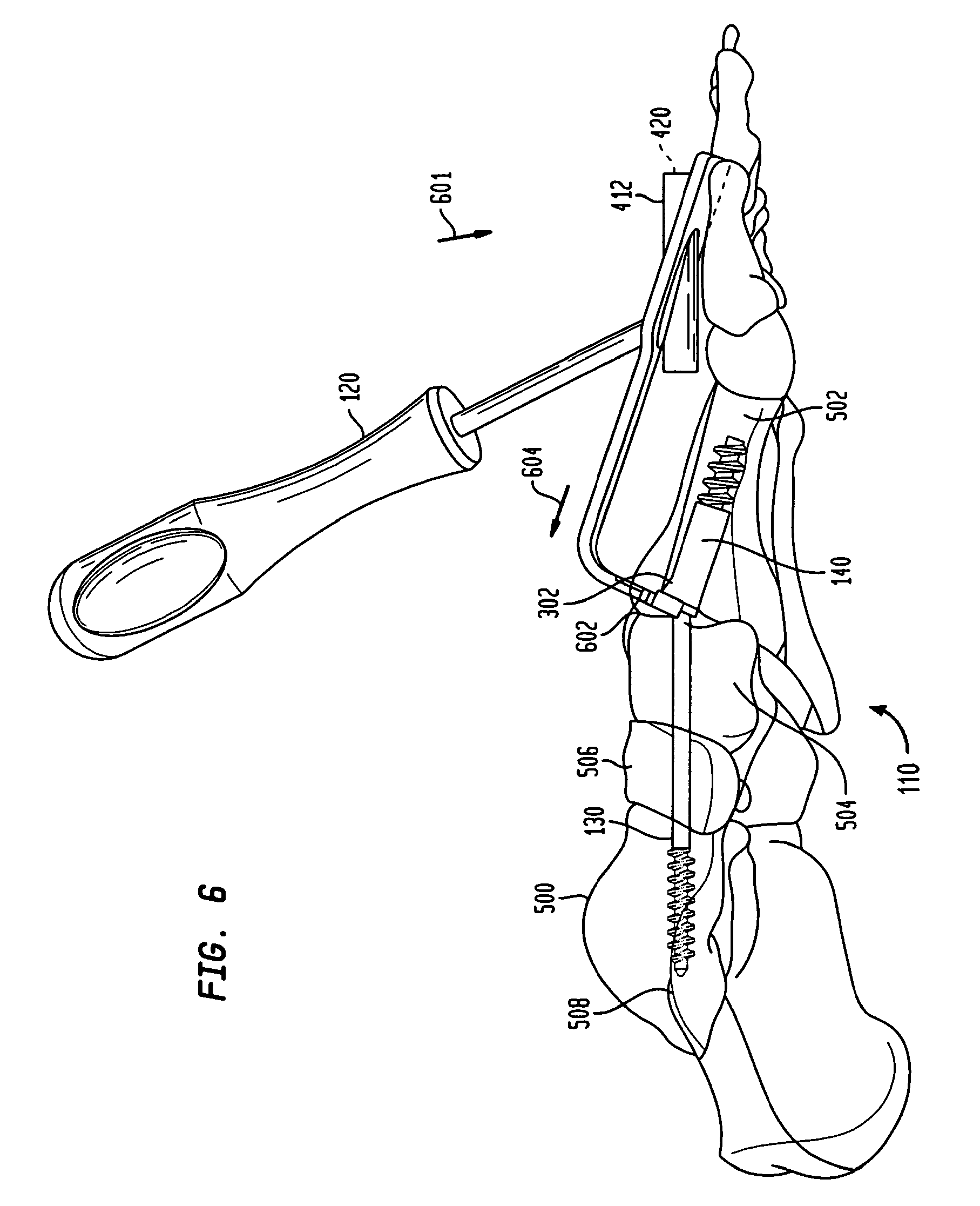
FIG. 6 is a side view of the assembled intramedullary fixation assembly shown in FIG. 5 according to the preferred embodiment of the invention.
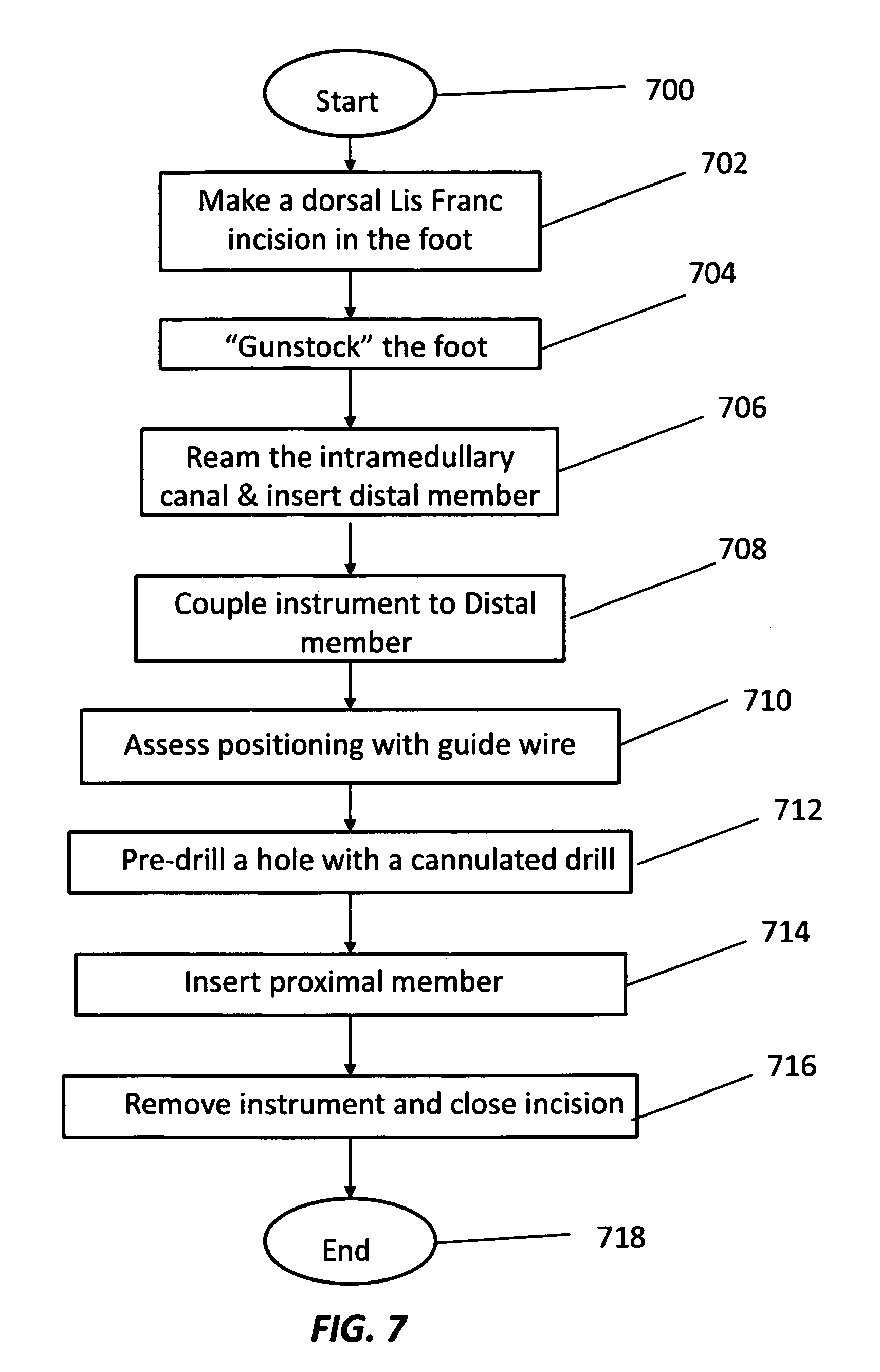
FIG. 7 is a flow chart illustrating the method of coupling the intramedullary fixation assembly shown in FIGS. 1-6 to tarsal and metatarsal bones in a patient's foot according to the preferred embodiment of the invention.
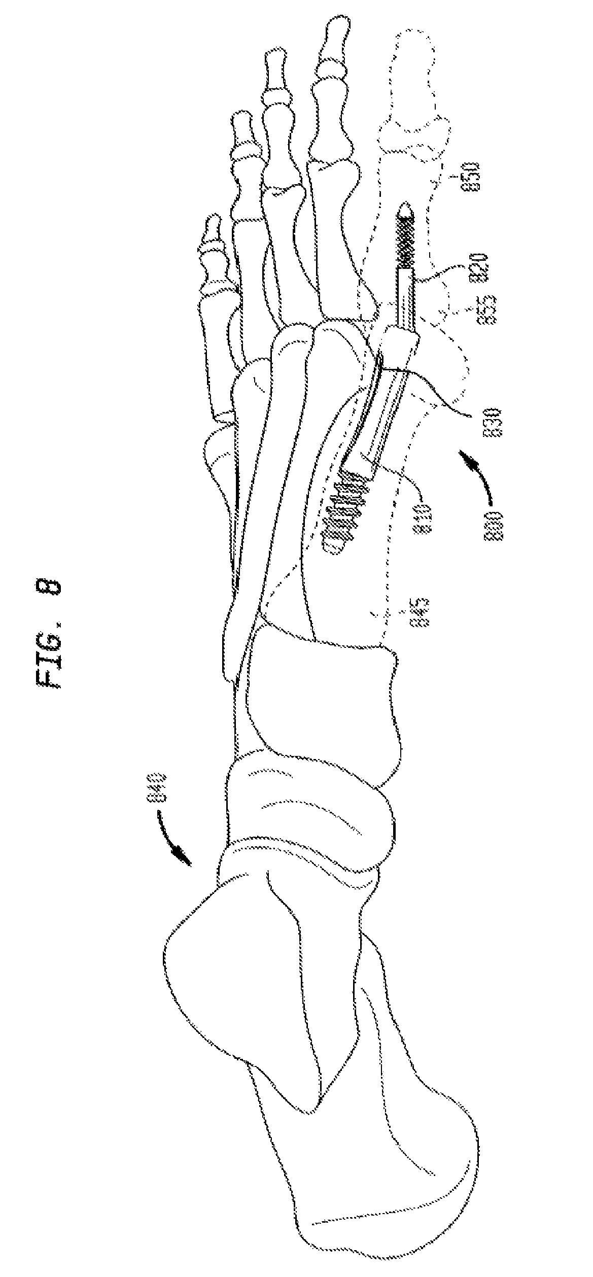
FIG. 8 is a perspective view of an assembled intramedullary fixation assembly inserted into the metatarsal and trapezial bones of a patient's foot according to an alternate embodiment of the invention.
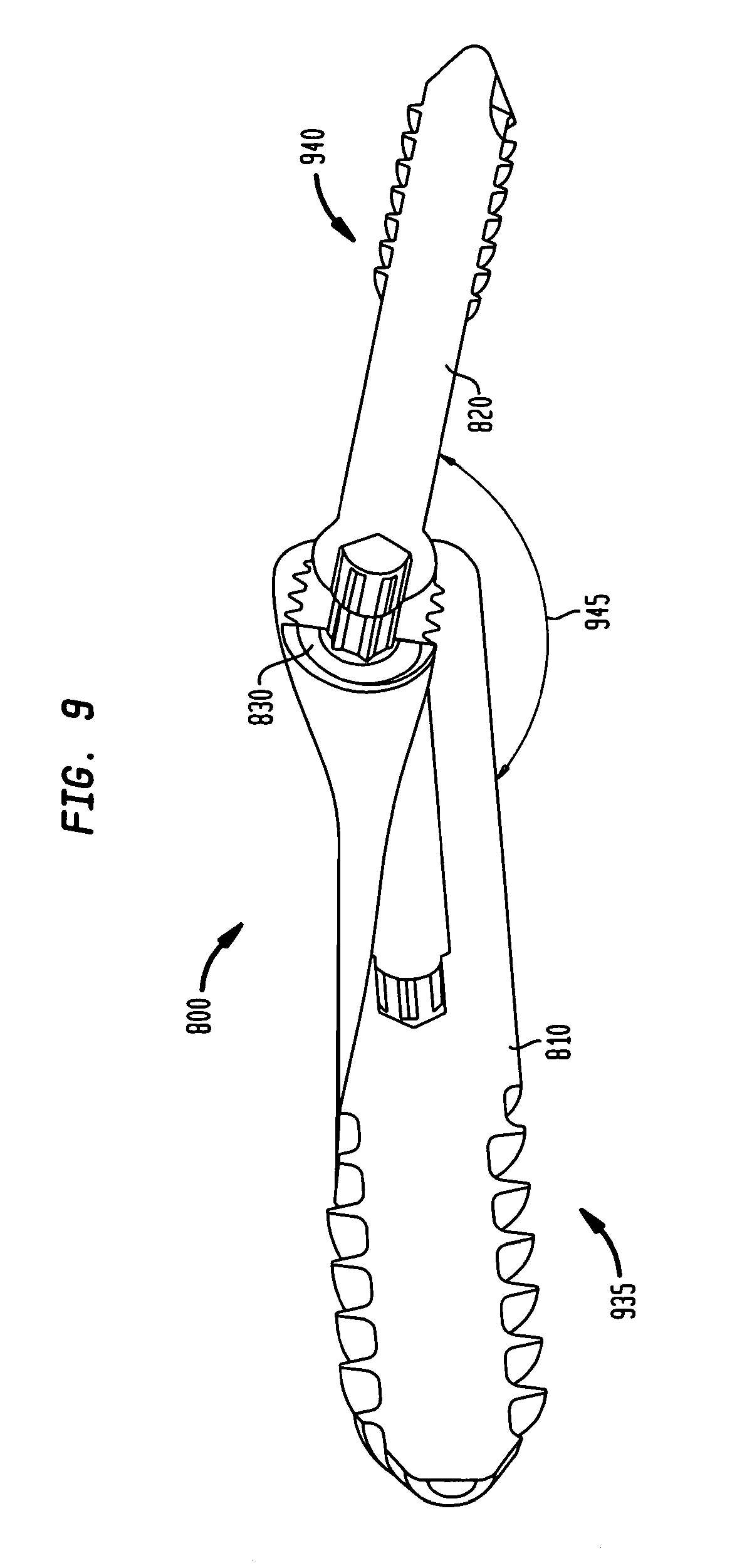
FIG. 9 is a perspective cross-sectional view of the intramedullary fixation assembly according to the alternate embodiment of the invention.
FIG. 10A is a perspective view of a metatarsal implant member used in the intramedullary fixation assembly shown in FIG. 8 according to the alternate embodiment of the invention.
FIG. 10B is a perspective cross-sectional view of the metatarsal implant member used in the intramedullary fixation assembly shown in FIG. 10A according to the alternate embodiment of the invention.
FIG. 11 is a perspective cross-sectional view of a phalangeal implant member used in the intramedullary fixation assembly shown in FIG. 8 according to the alternate embodiment of the invention.
FIG. 12 is a perspective cross-sectional view of a locking set screw used in the intramedullary fixation assembly shown in FIG. 8 according to the alternate embodiment of the invention.
FIG. 13 is a flow chart illustrating the method of coupling the intramedullary fixation assembly shown in FIGS. 8-12 to metatarsal and phalangeal bones in a patient's foot according to the alternate embodiment of the invention.
FIG. 14 is a perspective view of an intramedullary fixation assembly according to the alternate embodiment of the invention.
FIG. 15 is a perspective view of the intramedullary fixation assembly shown in FIG. 14 according to the alternate embodiment of the invention.
FIG. 16 is a perspective view of a metatarsal implant member used in the intramedullary fixation assembly shown in FIGS. 14-15 according to the alternate embodiment of the invention.
FIG. 17 is a perspective view of a phalangeal implant member used in the intramedullary fixation assembly shown in FIGS. 14-15 according to the alternate embodiment of the invention.
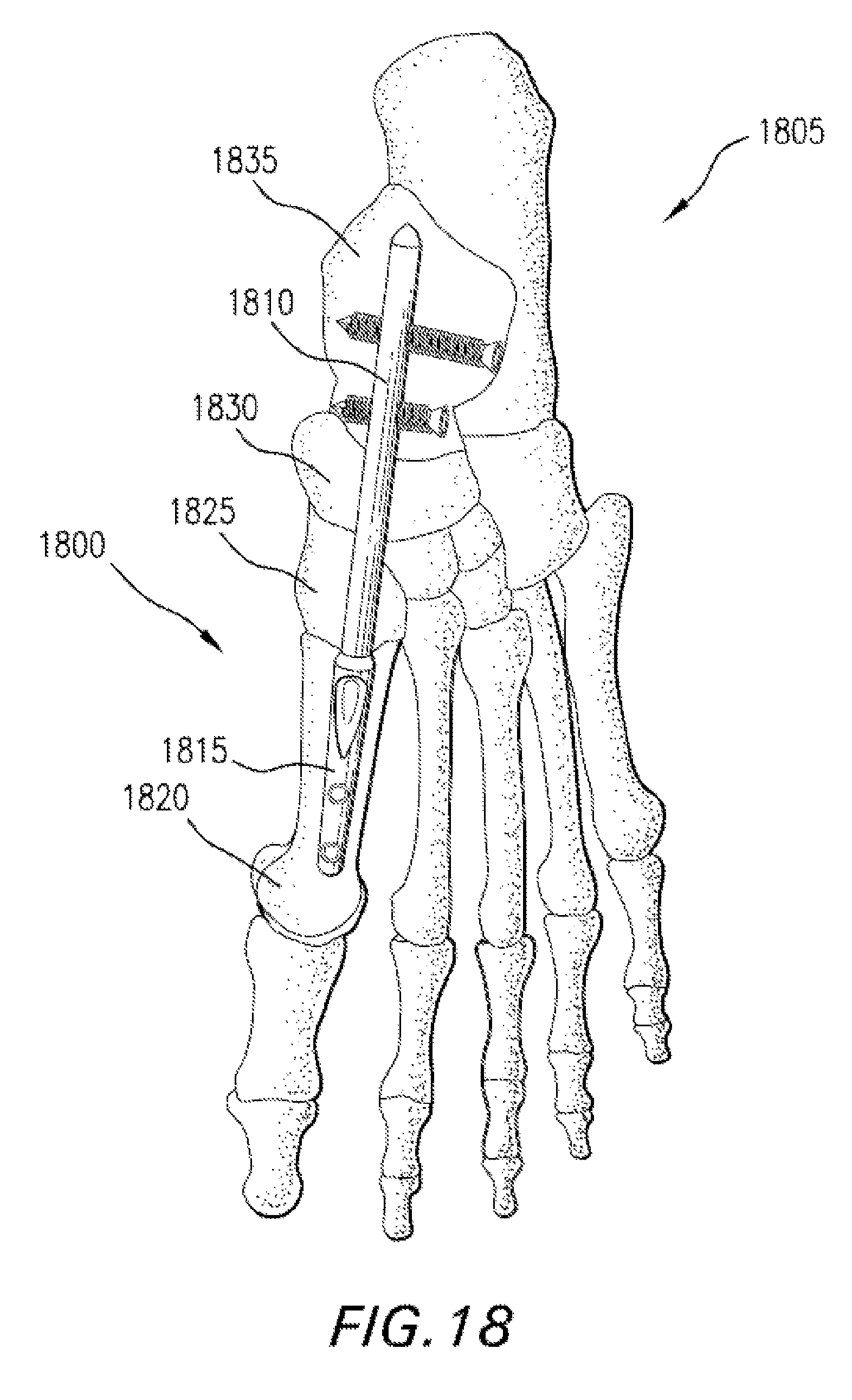
FIG. 18 is a perspective view of an assembled intramedullary fixation assembly inserted into the bones of a patient's foot according to an alternate embodiment of the invention.
FIG. 19 is a perspective view of the intramedullary fixation assembly shown in FIG. 18 according to the alternate embodiment of the invention.
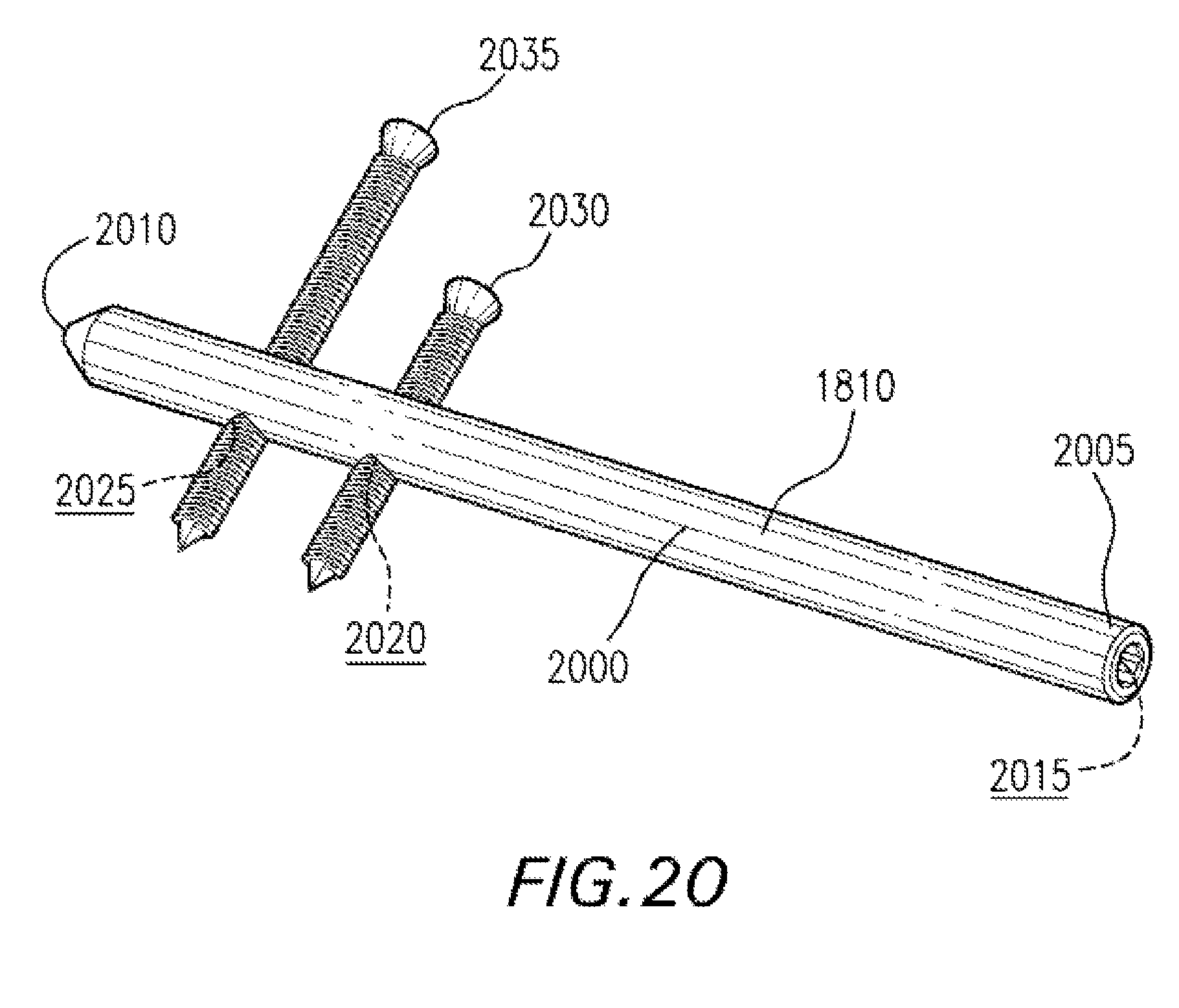
FIG. 20 is a perspective view of a proximal member used in the intramedullary fixation assembly shown in FIGS. 18-19 according to the alternate embodiment of the invention.
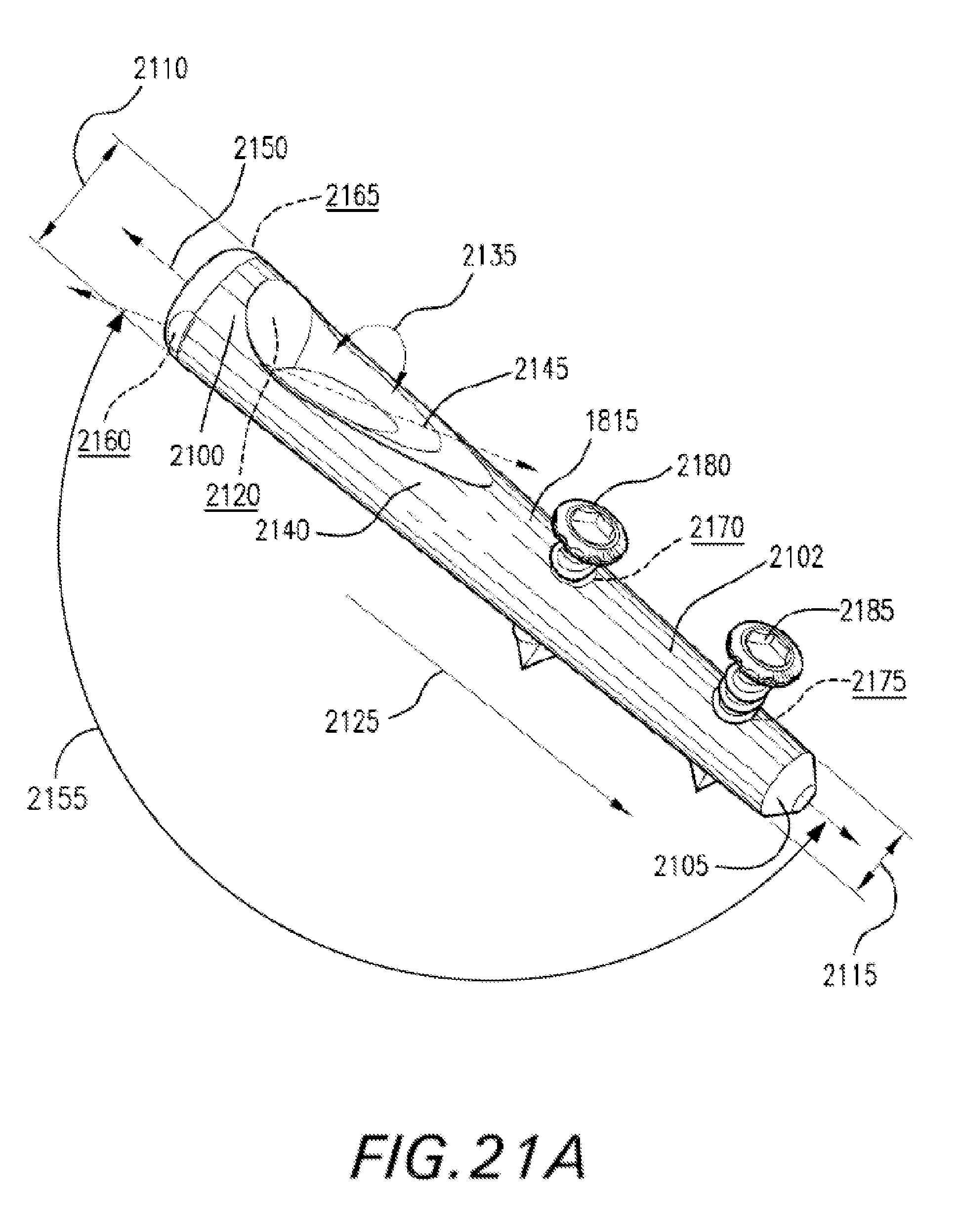
FIG. 21A is a perspective view of a distal member used in the intramedullary fixation assembly shown in FIGS. 18-19 according to the alternate embodiment of the invention.
FIG. 21B is a perspective partial cross-sectional view of the distal member shown in FIG. 21A according to an alternate embodiment of the invention.
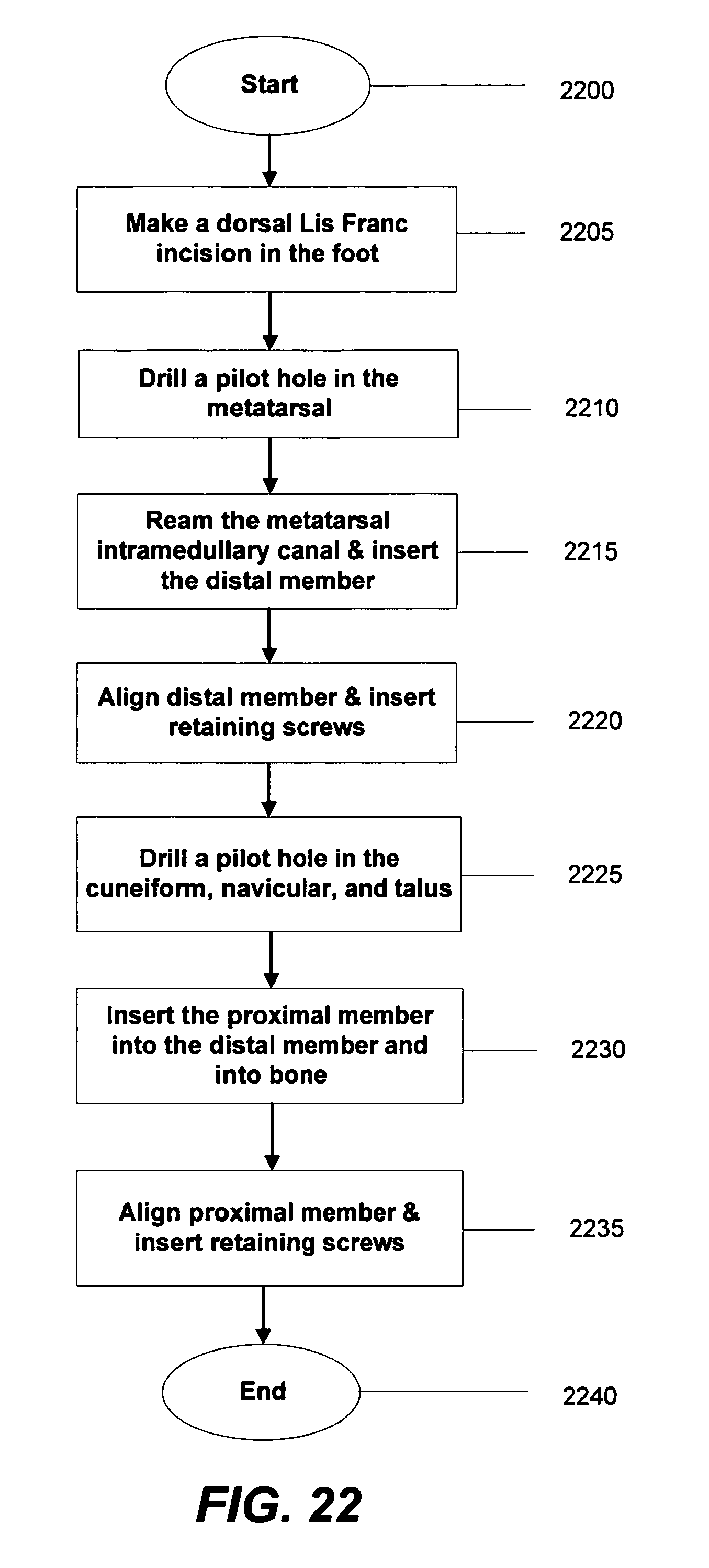
FIG. 22 is a flow chart illustrating the method of coupling the intramedullary fixation assembly shown in FIGS. 18-21B to bones in a patient's mid-foot region according to the alternate embodiment of the invention.
DETAILED DESCRIPTION
The invention may be understood more readily by reference to the following detailed description of preferred embodiment of the invention. However, techniques, systems and operating structures in accordance with the invention may be embodied in a wide variety of forms and modes, some of which may be quite different from those in the disclosed embodiment. Consequently, the specific structural and functional details disclosed herein are merely representative, yet in that regard, they are deemed to afford the best embodiment for purposes of disclosure and to provide a basis for the claims herein, which define the scope of the invention. It must be noted that, as used in the specification and the appended claims, the singular forms "a", "an", and "the" include plural referents unless the context clearly indicates otherwise.
Referring now to FIG. 1, there is shown a fixation system 100 which is made in accordance with the teachings of the preferred embodiment of the invention. As shown, the fixation system 100 includes an intramedullary fixation assembly 110, comprising a proximal screw member 130 and a distal member 140. Proximal screw member 130 is provided on proximal end 135 of assembly 110 and is coupled to a distal member 140 that is provided on the distal end 145 of the fixation assembly 110. Also, proximal screw member 130 makes a fixed angle 150 with distal member 140 and this angle 150 determines the angle for arch restoration. Moreover, fixation system 100 includes instrument 120 that is utilized to couple intramedullary fixation assembly 110 to the bones in the mid-foot region (not shown). It should be appreciated that in one non-limiting embodiment, intramedullary fixation assembly 110 may be made from a Titanium material, although, in other non-limiting embodiments, intramedullary fixation assembly 110 may be made from SST, PEEK, NiTi, Cobalt chrome or other similar types of materials.
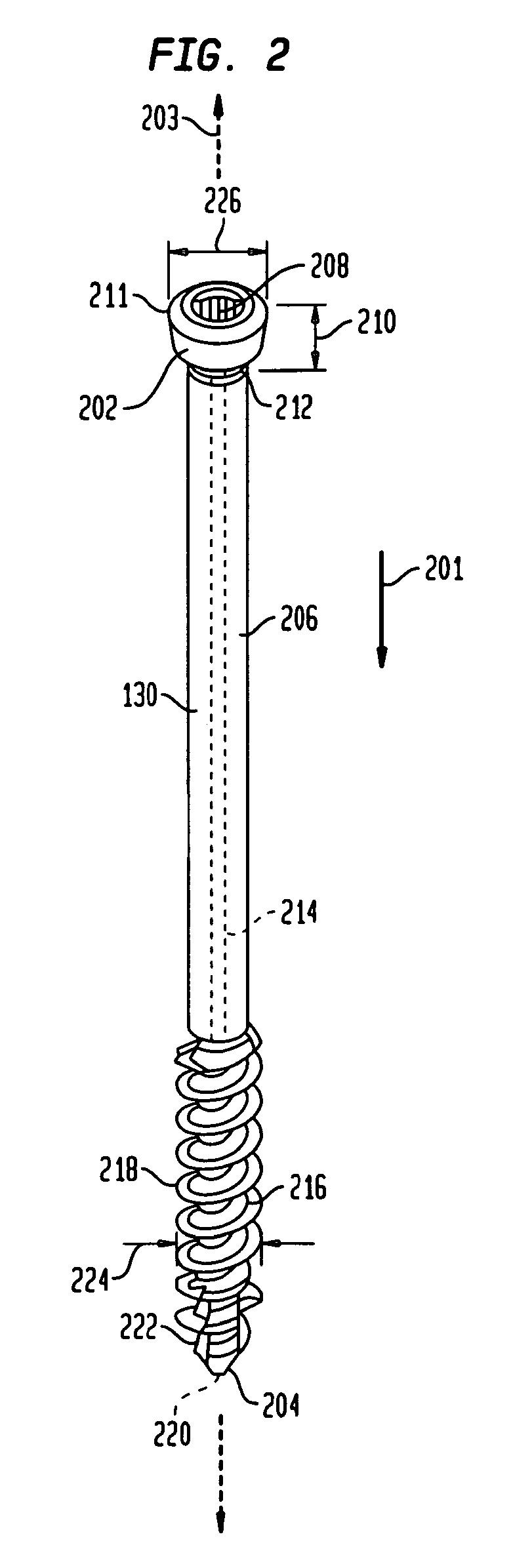
As shown in FIG. 2, proximal screw member 130 is generally cylindrical in shape and extends from first bulbous portion 202 to second tapered end 204. End 204 has a diameter that is slightly smaller than diameter 226 of bulbous portion 202. Additionally, bulbous portion 202 has a taper, such as a Morse taper, with a width that decreases from end 211 to end 212. The taper allows for a locked interference fit with tapered aperture 316 when tapered bulbous portion 202 is combined with tapered aperture 316, shown and described below. Moreover, bulbous portion 202 is generally circular and has a generally hexagonal torque transmitting aperture 208 that traverses length 210 of bulbous portion 202. However, a star-shaped aperture, a square-shaped aperture, or any other shaped aperture may be utilized without departing from the scope of the invention. Torque transmitting aperture 208 is utilized to transmit a torque from bulbous portion 202 to tapered end 204 by rotating bulbous portion 202.
Further, proximal screw member 130 has a first smooth exterior portion 206 extending from end 212 of bulbous portion 202. Portion 206 comprises an internal aperture 214 that longitudinally traverses portion 206 in direction 201. Portion 206 terminates into a second generally tubular portion 216. Portion 216 may comprise internal circular aperture 220 that longitudinally traverses inside portion 216. Internal circular aperture 220 is aligned with apertures 214 and 208 along axis 203 to form a continuous opening (i.e., a cannula) from bulbous portion 202 to end 204. The continuous opening or cannula is provided to interact with a guide wire (not shown) by receiving the guide wire within the continuous opening thereby positioning and locating the proximal member 130. In other non-limiting embodiments, the proximal member 130 may be provided without apertures 220 and 214 (i.e., the proximal member is solid).
Furthermore, tubular portion 216 has a plurality of circular threads, such as threads 218, which are circumferentially disposed on the external surface of portion 216 and, with threads 218 having an external diameter 224. Portion 216 may also be provided with a self-tapping leading edge 222 to provide portion 216 with the ability to remove bone material during insertion of proximal screw member 130 into bone. It should be appreciated that the length of the proximal member 130 may be selected of varying lengths to allow a surgeon to fuse different joints in a foot (not shown).
As shown in FIGS. 3A-3B, distal member 140 of the preferred embodiment is generally tubular in shape and tapers from a first end 302 to a second end 304 (i.e. end 302 has a diameter 306 that is slightly larger than diameter 308 of end 304). However, in another non-limiting embodiment, distal member 140 has a constant width from first end 302 to second end 304. Further, first end 302 is generally semi-spherical in shape and has an internal circular aperture 316, which traverses end 302 along direction 301 (i.e. end 302 is generally "donut" shaped). Additionally, circular aperture 316 emanates from surface 322, such that portion 310 has a generally tapered aperture 316 provided in portion 310. Circular aperture 316 comprises slope 320 from first end 302 to end 323 of portion 310. Further, aperture 316 is aligned along axis 303, which is offset from horizontal axis 305 of distal member 140. Axis 303 forms an angle 150 with horizontal axis 305 that determines the angle for arch restoration, as shown in FIG. 3A. Angle 150 may be any angle greater than 90 degrees and less than 180 degrees. Tapered aperture 316 when combined with tapered bulbous portion 202, shown in FIG. 2, creates a locked interference fit between proximal member 130 and distal member 140. First end 302 has a plurality of substantially similar grooves 326 and 328, which form an "L-shape" with surface 330 of end 302. Grooves 326 and 328 are provided to receive instrument 120 of fixation system 100, which is later described. In other non-limiting embodiments, other similar instruments may be provided to be received within grooves 326 and 328.
Distal member 140 further comprises a generally smooth portion 310 coupled to end 302. Portion 310 has a generally hexagonal shaped aperture 312, which opens into aperture 316 and which longitudinally traverses through portion 310 in direction 301. In other non-limiting embodiments, a star-shaped aperture, a square-shaped aperture, or any other shaped aperture may be utilized. Circular aperture 316 has a diameter 314 that is slightly larger than external diameter 224 of portion 216 and 206 of proximal screw member 130, with portions 216 and 206 being slidably received within aperture 316 of portion 310. Aperture 316 has a diameter that is smaller than diameter 226 of bulbous portion 202.
Portion 310 of distal member 140 terminates into a second generally cylindrical portion 318 which has a plurality of threads 324, which are circumferentially disposed on the external surface of portion 318. Portion 318 has an internal circular aperture 327 which is longitudinally coextensive with portion 318 in direction 301. Circular aperture 327 aligns with aperture 312 to form a continuous opening from end 302 to end 304.
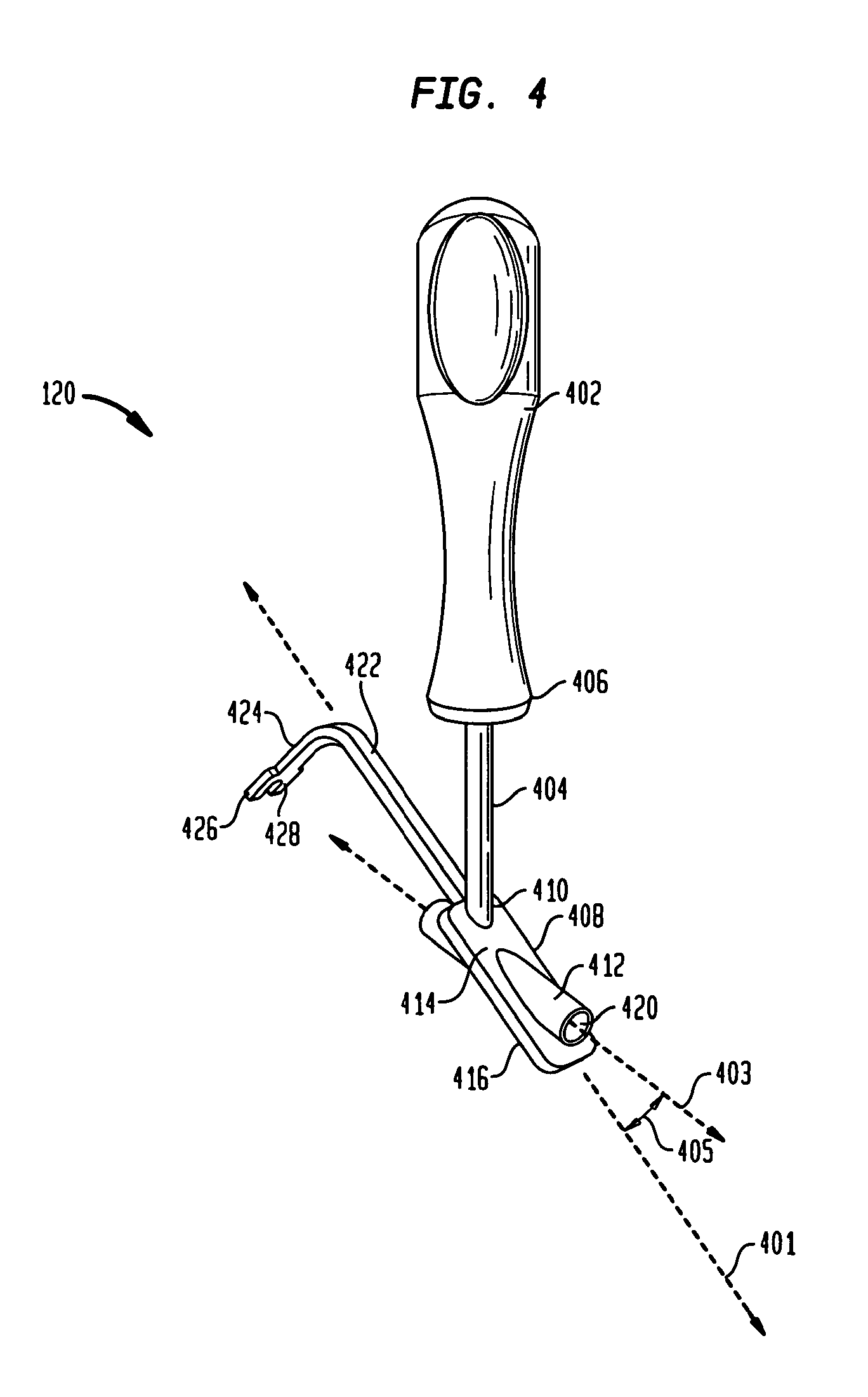
As shown in FIG. 4, instrument 120 is illustrated for coupling proximal screw member 130 to distal member 140. Particularly, instrument 120 includes a handle portion 402 coupled to a rod portion 404. Rod portion 404 emanates from handle portion 402 at end 406 and terminates into a rectangular planar portion 408 at end 410. Planar portion 408 is aligned along axis 401 and is fixably coupled to a generally cylindrical tubular portion 412 (i.e., an aiming device). Portion 412 traverses portion 408 from top surface 414 to bottom surface 416. Further, tubular portion 412 is aligned along dissimilar axis 403, forming an angle 405 with axis 401. Also, tubular portion 412 has a through aperture 420 that longitudinally traverses portion 412 along axis 403.
Planar portion 408 is coupled to planar portion 422, with portion 422 having a width slightly smaller than width of portion 408. Portion 422 terminates into a generally "U-shaped" portion 424 with portion 424 being orthogonal to portion 422. Further, portion 424 has a plurality of substantially similar sides 426 and 428 which are provided to be slidably coupled to grooves 326 and 328 of distal member 140.
In operation, sides 426 and 428 of instrument 120 are received in respective grooves 326 and 328 of distal member 140, of FIGS. 3A-3B, thereby slidably coupling distal member 140 to instrument 120. In this position, axis 303 of aperture 316 is aligned along substantially the same axis as axis 403 of instrument 120. Proximal screw member 130 is coupled to distal member 140 by slidably coupling portions 206 and 216 through aperture 420 of tubular portion 412. Tubular portion 412 guides proximal screw member 130 through internal aperture 420 and into aperture 316 on surface 322 and may also guide a Kirschner wire (K wire) or a drill. Proximal screw member 130, of FIG. 2, travels into bone as portions 216 and 206 travel further through aperture 316 at end 302 until bulbous portion 202 is restrained by surface 322 and end 302. Aperture 316, being tapered along axis 303, causes proximal screw member 130 to form an angle 150 with distal member 140, with proximal member 130 being aligned along an axis 303, which is substantially the same axis as axis 403 of tubular portion 412 of instrument 120.
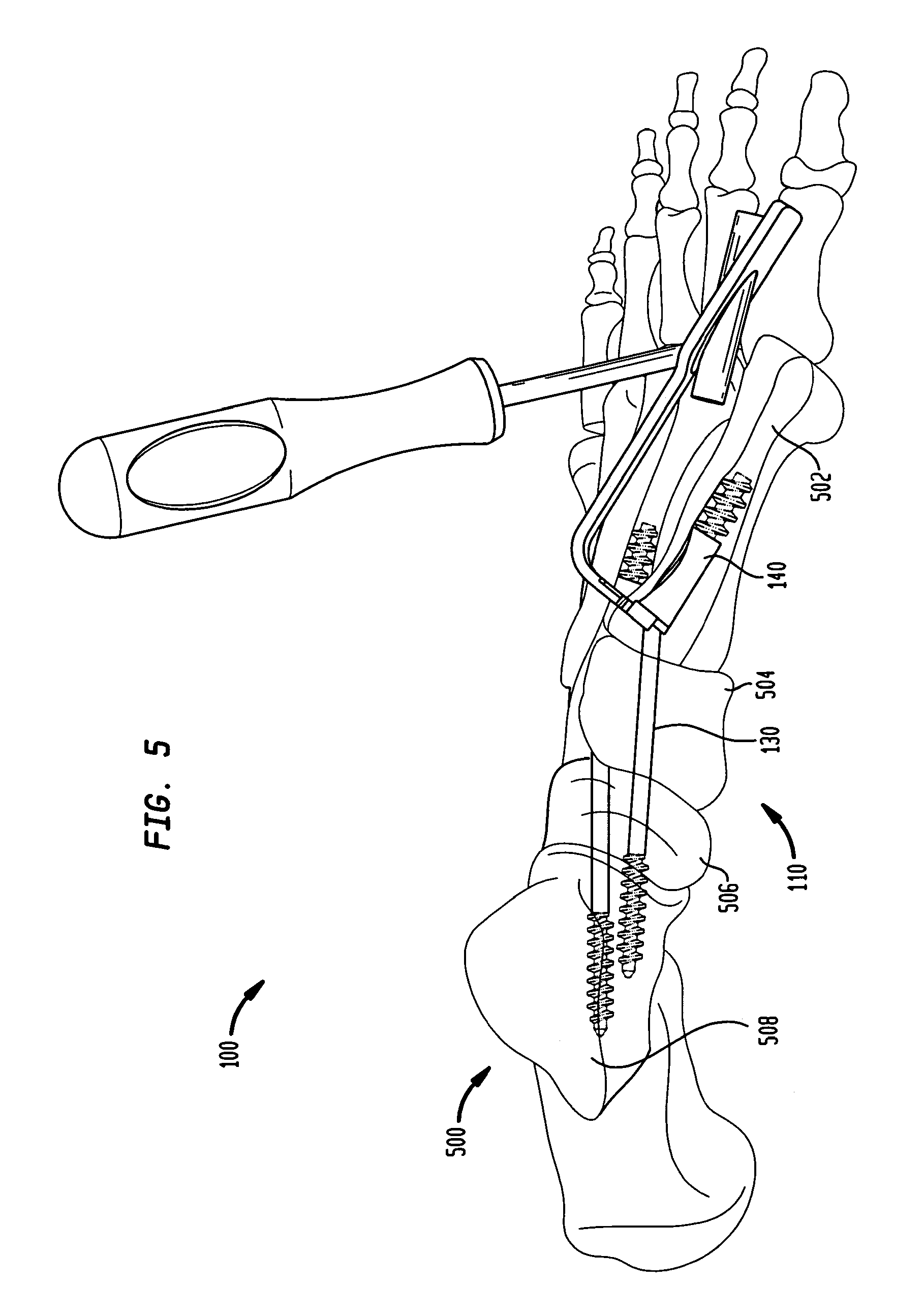
In operation, and as best shown in FIGS. 5, 6 and 7, the fixation system 100 utilizes the intramedullary fixation assembly 110 for treating and fixating the deteriorated and damaged or fractured bones in the human foot 500. This restores the arch in a human foot 500 by coupling the intramedullary fixation assembly 110 to the human foot 500 of a left leg. In one-non limiting example, and as shown in FIG. 5, the intramedullary assembly 110 is coupled to the medullary canals of the first metatarsal 502, medial cuneiform 504, navicular 506 and talus bone 508. Talus bone 508 makes up part of the ankle joint where the threaded portion 216 of the proximal screw member 130 of the intramedullary assembly 110 is threadably coupled. The medial cuneiform 504 and navicular 506 bones are most affected by Diabetic Charcot foot disorder that causes deterioration and collapse of the arch of the foot 500. It should be appreciated that the intramedullary assembly 110 may be used within each of the five rays, with a ray representing a line drawn from each metatarsal bone to the talus. The angulation in the smaller rays will be smaller than the two rays (i.e., a line from the first and second metatarsal bones to the talus bone). Also, the diameter of distal member 140 will decrease from the large ray to the small ray. In one non-limiting example, the angulation may be any angle greater than 90 degrees and less than 180 degrees. For example, the angle for the first ray may be 150-170 degrees and the angles for the other rays may be 160-175 degrees.
As shown in FIGS. 6 and 7, the intramedullary fixation assembly 110 may be utilized to reconstruct an arch in a mid-foot region of a human foot 500. As shown, the method starts in step 700 and proceeds to step 702, whereby a Dorsal Lis Franc incision (i.e., mid-foot incision) (not shown) is made in foot 500 in order to gain access to the joint. In step 704, the joint capsule is separated by "Gunstocking" foot 500 in direction 601 (i.e., the foot 500 is bent mid-foot) to expose the articular surface 602 and the articulating cartilage is removed. Next, in step 706, the intramedullary canal is reamed and the distal member 140 is inserted into the intramedullary canal (not shown) of the metatarsal 502. In other non-limiting embodiments, the distal member 140 may be inserted by impaction, by press fit, by reaming a hole in the intramedullary canal (not shown) or substantially any other similar strategy or technique.
Next, in step 708, the instrument 120 is coupled to the distal member 140 by coupling sides 426 and 428 of instrument 120 to respective grooves 326 and 328. In step 710, initial positioning of the proximal member 130 is assessed with the use of a guide wire through portion 412 (i.e., aiming device). Next, in step 712, a countersink drill is inserted through portion 412 and the proximal cortex is penetrated. In this step, a cannulated drill or guide wire is used to pre-drill the hole through the joints selected for fusion. In step 714, the proximal screw member 130 is inserted over the guide wire and into the distal member 140. Particularly, the proximal member 130 is inserted through tubular portion 412 (i.e., aiming device), causing proximal member 130 to travel through internal longitudinal aperture 420, into distal member 140 and further into bones 504, 506 and 508 until rigid connection with the tapered aperture 316 is made, thereby compressing the joint. In one non-limiting embodiment, a locking element (not shown) such as a plate or a washer is coupled to end 302 of the intramedullary fixation assembly 110 to further secure proximal threaded member 130 to distal member 140. Next, in step 716 the instrument 120 is removed and the dorsal Lis Franc (i.e., mid-foot) incision is closed. The method ends in step 718.
It should be appreciated that a plurality of intramedullary fixation assemblies, such as intramedullary fixation assembly 110, may be inserted into any of the bones of a foot 500 such as, but not limited to the metatarsal, cuneiform, calcaneus, cuboid, talus and navicular bones, in order to restore the natural anatomical shape of the arch of the foot 500. Thus, the fixation system 100, in one non-limiting embodiment, is utilized to couple the intramedullary fixation assembly 110 to the foot 500, which causes the metatarsal 504, medial cuneiform 504, navicular 506 and talus 508 bones to be aligned to the proper anatomical shape of an arch when assembled within foot 500. It should be appreciated that the intramedullary fixation assembly 110 is delivered through a dorsal midfoot incision, thereby reducing the disruption to the plantar tissues and/or the metatarsal heads while at the same time minimizing the tension on the skin. This allows for improved wound closure, reduced operating room time, reduction in the number of incisions required and reduction in the total length of incisions. It should also be appreciated that in other non-limiting embodiments, the intramedullary assembly 110 may be utilized with graft material (i.e., autograft, allograft or other biologic agent).
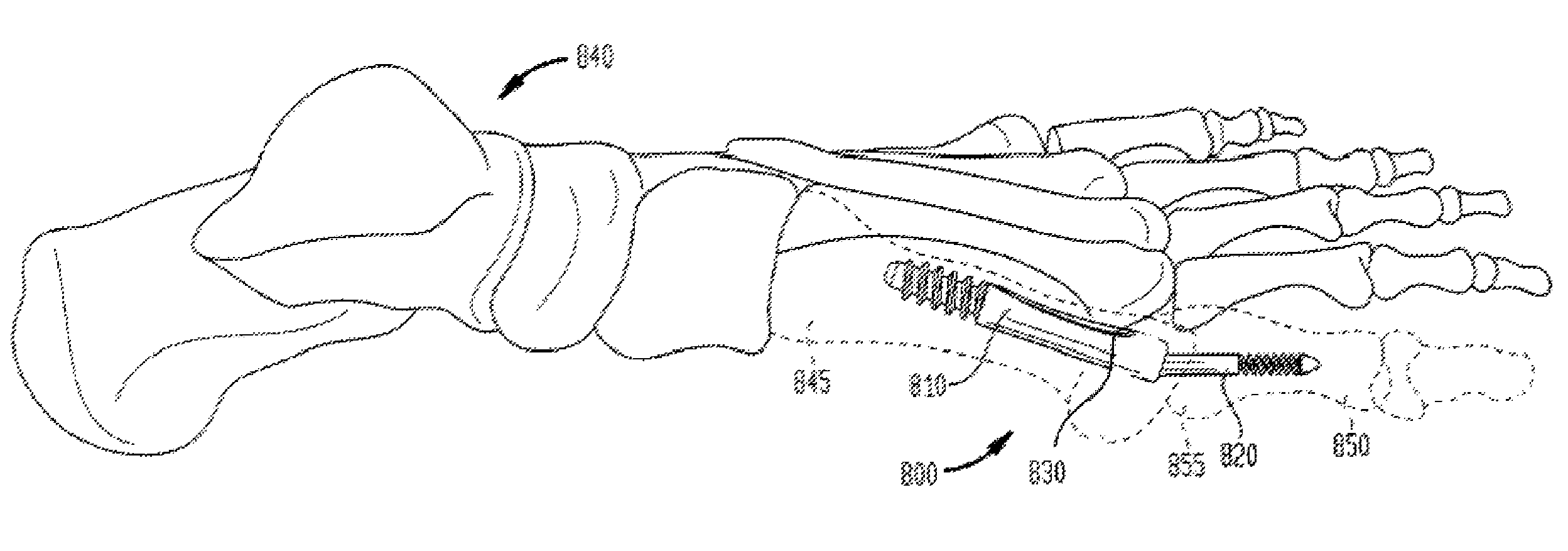
In an alternate embodiment, as shown in FIG. 8, an intramedullary fixation assembly 800 may comprise three interconnected members for the internal fixation of the first metatarsal 845 to the first proximal phalange 850 in the human foot 840 or any other appropriate use for the internal fixation of the other bones in the human foot 840. The interconnected members of the intramedullary fixation assembly 800 may be inserted into the medullary canals of the first metatarsal 845 and the first proximal phalange 850 in order to restore the angle in the toes of a human foot 840. Particularly, the intramedullary fixation assembly 800 may comprise a metatarsal implant member 810, a phalangeal implant member 820 and an optional locking set screw 830.
As shown in FIG. 9, the intramedullary fixation assembly 800 comprises the metatarsal implant member 810, which is provided on the proximal end 935 of the intramedullary fixation assembly 800, the phalangeal implant member 820 provided on the distal end 940 and the optional locking set screw 830 provided to threadably couple to the metatarsal implant member 810, thereby pressure coupling the metatarsal implant member 810 to the phalangeal implant member 820. Optional locking set screw 830 thereby locks the metatarsal implant member 810 to the phalangeal implant member 820 and allows for incremental adjustment of the position of phalangeal implant member 820 within the metatarsal implant member 810 as will be shown and described.
In its implanted position, metatarsal implant member 810 is at a fixed angle 945 with phalangeal implant member 820 and this angle 945 may be adjusted in order to set the angle for restoration. It should be appreciated that in one non-limiting embodiment, intramedullary fixation assembly 800 may be made from a Titanium material, although, in other non-limiting embodiments, intramedullary fixation assembly 800 may be made from SST, PEEK, NiTi, Cobalt chrome or other similar types of materials.
As shown in FIGS. 10A-10B, metatarsal implant member 810 of the embodiment is generally tubular in shape and tapers from a first end 1002 to a second end 1004 (i.e. end 1002 has a diameter 1006 that is slightly larger than diameter 1008 of end 1004). However, in another non-limiting embodiment, metatarsal implant member 810 has a constant width from first end 1002 to second end 1004. Further, first end 1002 is generally semi-spherical in shape and has an internal circular aperture 1016, which traverses end 1002 along direction 1001 (i.e. end 1002 is generally "donut" shaped). Additionally, circular aperture 1016 is aligned along axis 1003, which is offset from horizontal axis 1005 at an angle 1050. Angle 1050 causes circular aperture 1016 to emanate from surface 1022, such that circular aperture 1016 on cylindrical portion 1010 is generally tapered with the diameter 1030 being slightly smaller than diameter 1032.
It should be appreciated that angle 1050 initially determines the angle for restoration, as shown in FIG. 10A. Angle 1050 may be any angle greater than 90 degrees and less than 180 degrees. Circular aperture 1016 also includes a plurality of substantially similar threads 1028 that are provided on interior surface 1026 of metatarsal implant member 810. The plurality of substantially similar threads 1028 when combined with head portion 1105 of phalangeal implant member 820, shown in FIG. 11, creates a locked interference fit between metatarsal implant member 810 and phalangeal implant member 820. Circular aperture 1016 has a diameter 1014 that is provided to receive head portion 1105 of phalangeal implant member 820, which will be shown in FIG. 11.
Also, metatarsal implant member 810 further comprises a generally smooth portion 1010 coupled to end 1002. Portion 1010 has a generally hexagonal shaped aperture 1012 aligned along axis 1005.
In other non-limiting embodiments, a star-shaped aperture, a square-shaped aperture, or any other shaped aperture may be utilized. Aperture 1012 emanates from circular aperture 1016, traverses through portion 1010 in direction 1001 and terminates into a generally cylindrical portion 1018. In other non-limiting embodiments, aperture 1012 is longitudinally coextensive with portion 1018 in direction 1001 and emanates from second end 1004. In this manner, a continuous opening from end 1002 to end 1004 may be formed to receive a Kirschner wire (K wire) or a drill.
Further, portion 1018 has a plurality of substantially similar circumferential threads, such as threads 1024, which are circumferentially disposed on the external surface of portion 1018. It should be appreciated that plurality of circumferential threads, such as threads 1024, are provided so that rotating metatarsal implant member 810 causes the plurality of circumferential threads 1024 to grip or catch the medullary canal of first metatarsal 845 (shown in FIG. 8) causing metatarsal implant member 810 to travel into the first metatarsal 845. It should be appreciated that metatarsal implant member 810 may be utilized in any metatarsal for restoration of the angle in the human foot. It should also be appreciated that the metatarsal implant member may be utilized for fusion of other joints in the human body.
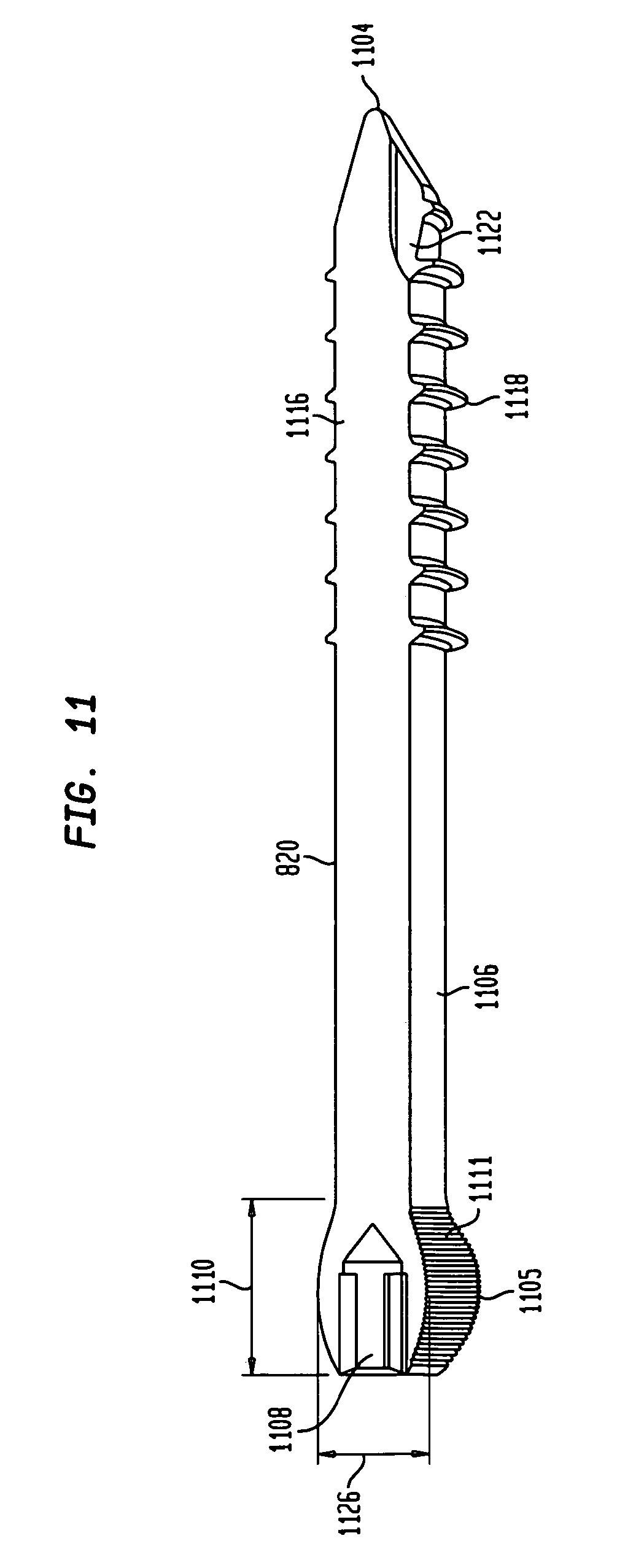
As shown in FIG. 11, phalangeal implant member 820 is generally cylindrical in shape, has a generally solid body and extends from a spherical head portion 1105 to tapered end 1104. Spherical head portion 1105 is generally spherical in shape and has a generally hexagonal torque transmitting aperture 1108 traversing length 1110 of head portion 1105. In other non-limiting embodiments, a star-shaped aperture, a square-shaped aperture, or any other shaped aperture of any length may be utilized without departing from the scope of the invention. Torque transmitting aperture 1108 is utilized to transmit a torque from head portion 1105 to tapered end 1104 when head portion 1105 is rotated. The largest diameter 1126 of head portion 1105 is slightly larger than diameter 1032 of circular aperture 1016 on metatarsal implant member 810, which was shown previously in FIGS. 10A-B.
Head portion 1105 further has a plurality of generally flat edges 1111 (i.e., head portion 1105 has a plurality of step-like protrusions) which are provided to engage circular aperture 1016. The flat edges 1111 allow for the phalangeal implant member 820 to be coupled at a plurality of angles to metatarsal implant member 810. Each of the plurality of edges 1111 allows for a unique angle in a locked interference fit to be created by head portion 1105 within circular aperture 1016, shown in FIGS. 10A-B, as head portion 1105 of phalangeal implant member 820 is positioned within circular aperture 1016 of metatarsal implant member 810, which will be shown and described below
Further, phalangeal implant member 820 has a first smooth exterior portion 1106 extending from head portion 1105. Portion 1106 is generally cylindrical and terminates into a second generally cylindrical portion 1116, with exterior portion 1106 and cylindrical 1116 having a uniform diameter. Furthermore, cylindrical portion 1116 has a plurality of circular threads, such as threads 1118, which are circumferentially disposed on the external surface of portion 1116. Cylindrical portion 1116 may also be provided with a self-tapping leading edge 1122 to provide portion 1116 with the ability to remove bone material during insertion of the phalangeal implant member 820 into bone or other matter. It should be appreciated that the length of the phalangeal implant member 820 may be selected of varying lengths to allow a surgeon to fuse different joints (not shown). In other non-limiting embodiments, the phalangeal implant member 820 may have a continuous opening (i.e., a cannula) from torque transmitting aperture 1108 to tapered end 1104. The continuous opening or cannula may be provided to interact with a guide wire (not shown), such as a Kirschner wire, by receiving the guide wire within the continuous opening thereby positioning and locating the phalangeal implant 820.
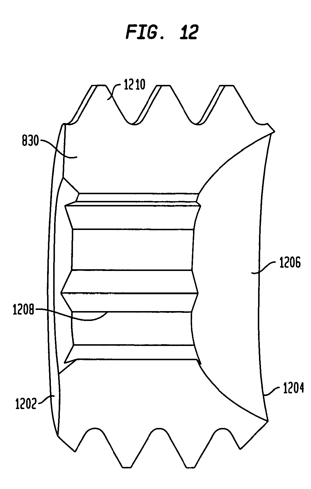
As shown in FIG. 12, intramedullary fixation assembly 800 may comprise an optional locking set screw 830 to couple the metatarsal implant member 810 to the phalangeal implant member 820. Locking set screw 830 is generally tubular in shape and extends from open first end 1202 to an open second end 1204. First end 1202 has a generally flat surface while second end 1204 has a semi-spherical groove 1206. The semi-spherical groove 1206 is provided to receive head portion 1105 of the phalangeal implant member 820 in an assembled intramedullary fixation assembly 800. Further, locking set screw 830 has a generally hexagonal torque-transmitting aperture 1208 that traverses from first end 1202 to second end 1204. In other non-limiting embodiments, a star-shaped aperture, a square-shaped aperture, or any other shaped aperture of any length may be utilized without departing from the scope of the invention.
Torque transmitting aperture 1208 is utilized to receive a torque shaped tool in order to rotate and couple locking set screw 830 to first metatarsal implant member 810 (not shown). Locking set screw 830 is also provided with a plurality of substantially similar circumferential threads 1210 in order to engage the plurality of threads 1028 on the interior surface 1026 of the metatarsal implant member 810 (shown in FIGS. 10A and 10B) and threadably couple (i.e., mechanically couple) the locking set screw 830 to the metatarsal implant member 810, thereby preventing the phalangeal implant member 820 from backing out of circular aperture 1016 on metatarsal implant member 810 and losing compression.
In operation, and as shown in FIGS. 8 and 13, the intramedullary fixation assembly 800 may be utilized to reconstruct an arch and/or angle in a metatarsal phalangeal joint of a human foot 840. As shown, the method starts in step 1300 and proceeds to step 1302, whereby a dorsal incision is made in the metatarsal phalangeal (MTP) joint 855 of foot 840 in order to gain access to the MTP joint 855. In step 1304, the joint capsule is separated by "Gunstocking" foot 840 (i.e., the foot 840 is bent at MTP joint 855) to expose the articular surfaces of the metatarsal 845 and first proximal phalange 850. The articulating cartilage is removed by denuding the cartilage in the MTP joint 855. Next, in step 1306, the intramedullary canal of the metatarsal 845 is reamed by drilling the metatarsal intramedullary canal and the metatarsal implant member 810 is inserted. The cylindrical portion 1018 of the metatarsal implant member 810 is inserted first into the intramedullary canal (of the metatarsal 845 to a predetermined depth until end 1002 is oriented at the opening of the MTP joint 855. In other non-limiting embodiments, the metatarsal implant member 810 may be inserted by impaction, by press fit, by reaming a hole in the intramedullary canal (not shown) or any other similar strategy or technique.
Next, in step 1308, the dorsal metatarsal cortex (not shown) is drilled and reamed to allow access to metatarsal implant member 810 from an anterior grade access. In step 1310, a cannulated drill or guide wire is used to pre-drill a pilot hole through the articular surface of the phalange 850. In step 1312, the phalangeal implant member 820 is inserted into the metatarsal implant member 810 and into the pre-drilled pilot hole by inserting the tapered end 1104 (shown in FIG. 11) into the circular aperture 1016 (shown in FIG. 10A-B) at surface 1022 and until the tapered end 1104 emanates from circular aperture 1016. Further, the phalangeal implant member 820 is inserted into the phalange 850 (shown in FIG. 8). Next in step 1314, the phalangeal implant member 820 is aligned and angle 845 (shown in FIG. 9) is formed and compression is applied to the intramedullary fixation assembly 800 by rotating the phalangeal implant member 820. The phalangeal implant member 820 is fixed at angle 845 (shown in FIG. 9). In optional step 1316, the locking set screw 830 is inserted into metatarsal implant member 810 to lock angle 845 (shown in FIG. 9) in place. Next, in step 1318, the dorsal incision is closed. The method ends in step 1320.
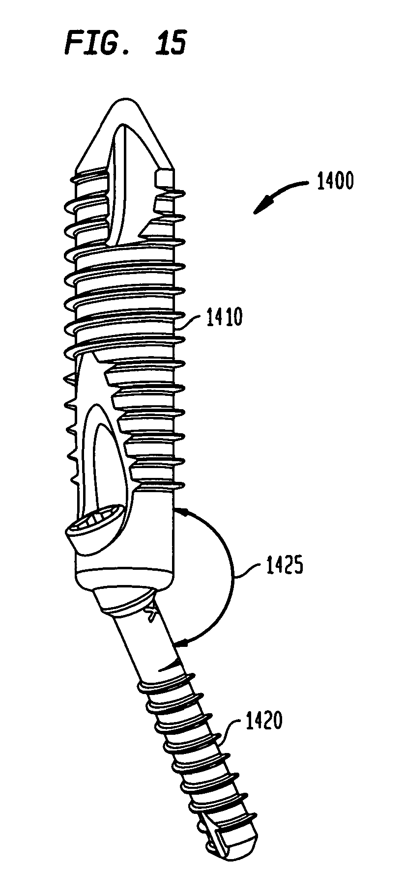
In an alternate embodiment, as shown in FIGS. 14 and 15, intramedullary fixation assembly 1400 is provided so that metatarsal implant member 1410 resides at a constant and fixed angle 1425 with phalangeal implant member 1420. The fixed angle 1425 may be any angle greater than 90 degrees and less than 180 degrees and may be selected by, in one example, a surgeon to provide for the internal fixation of the bones in the human foot.
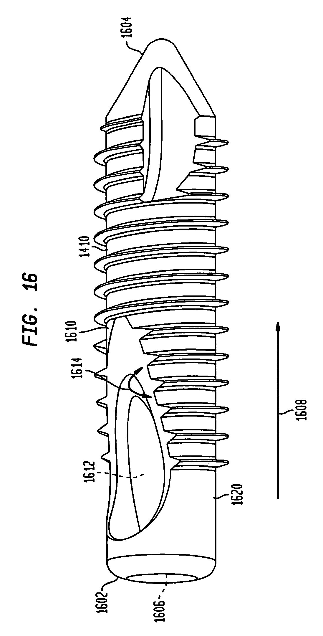
The metatarsal implant member 1410, shown in FIG. 16, is substantially similar to the distal member 140 shown and described in a previous embodiment in FIGS. 3A and 3B, and is generally tubular in shape and tapers from a first end 1602 to a second end 1604 (i.e. end 1602 has a diameter that is slightly larger than diameter of end 1604). However, in another non-limiting embodiment, metatarsal implant member 1410 has a constant width from first end 1602 to second end 1604. Further, first end 1602 has an internal circular aperture 1606 partially traversing metatarsal implant member 1410 along direction 301. Additionally, metatarsal implant member 1410 has a longitudinal aperture 1612 emanating from surface 1610, such that aperture 1612 forms a slope 1614 from in portion 1620. Slope 1614 determines the angle for restoration of the bones in a foot when phalangeal implant member 1420 (not shown) is coupled to metatarsal implant member 1410 and locks the phalangeal implant member at the fixed angle.
Also, the phalangeal implant member 1420, shown in FIG. 17, is substantially similar to the proximal screw member 130 that was shown in a previous embodiment, however, phalangeal implant member 1420 includes bulbous portion 1430 having a constant diameter. In other non-limiting embodiments, bulbous portion 1430 may include a morse taper (i.e., the diameter decreases from end 1440 in direction 1445) The bulbous portion 1430 is provided to be received inside aperture 1606 so that phalangeal implant member 1420 resides at a fixed angle with respect to metatarsal implant member 1410.
It should be appreciated that a plurality of intramedullary fixation assemblies, such as intramedullary fixation assembly 800, may be inserted into any of the metatarsal and phalangeal bones of a foot 840 in order to restore the natural anatomical shape of the foot 840. It should also be appreciated that the intramedullary fixation assembly 800 is delivered through a dorsal incision, thereby reducing the disruption to the plantar tissues and/or the metatarsal heads while at the same time minimizing the tension on the skin. This allows for improved wound closure, reduced operating room time, reduction in the number of incisions required and reduction in the total length of incisions. It should also be appreciated that the intramedullary fixation assembly 800 may also be utilized to restore any of the other bones in the human body. It should also be appreciated that in other non-limiting embodiments, the intramedullary assembly 800 may be utilized with graft material (i.e., autograft, allograft or other biologic agent).
In an alternate embodiment, as shown in FIG. 18, an intramedullary fixation assembly 1800 comprises a proximal member 1810 (or "beam") coupled to a distal member 1815 for the internal fusion of the bones of the human foot 1805, such as, for example, the first metatarsal bone 1820, the medial cuneiform bone 1825, the navicular bone 1830, and the talus bone 1835. In other non-limiting embodiments, the intramedullary fixation assembly 1800 may be utilized for any other appropriate use for the internal fixation of the other bones. As shown, the interconnected members of the intramedullary fixation assembly 1800, in one non-limiting example, may be inserted into the medullary canals of the first metatarsal bone 1820, the medial cuneiform bone 1825, the navicular bone 1830, and the talus bone 1835 in order to restore the arch in the human foot 1805. It should be appreciated that the intramedullary fixation assembly 1800 may be used within each of the five rays, with a ray representing a line drawn from each metatarsal bone to the talus bone 1835. Also, the fourth or fifth rays may go into the Calcaneus bone.
Also as shown in FIG. 19, the intramedullary fixation assembly 1800 includes the proximal member 1810 located on the proximal end 1900 of the intramedullary fixation assembly 1800 and the distal member 1815 located on the distal end 1905 of the intramedullary fixation assembly 1800.
The angular position of the proximal member 1810 may be incrementally adjusted in relation to the distal member 1815, thereby allowing for positioning the intramedullary fixation assembly 1800 at various angles of fixation. In its implanted position, proximal member 1810 is at a fixed angle 1910 with distal member 1815, with angle 1910 defining the angle for arch restoration. It should be appreciated that in one non-limiting embodiment, intramedullary fixation assembly 1800 may be made from a Titanium material, although, in other non-limiting embodiments, intramedullary fixation assembly 1800 may be made from SST, PEEK, NiTi, Cobalt chrome or other similar types of materials.
Referring to FIG. 20, proximal member 1810 has a generally cylindrical shaped body 2000 that is generally coextensive with length of the body 2000. Body 2000 extends from first end 2005 to a second tapered end 2010. Body 2000 is generally smooth and contains an internal aperture or cannula (not shown) that is longitudinally coextensive with body 2000. Moreover, end 2005 is generally circular and includes a generally hexagonal torque transmitting aperture 2015. In other non-limiting embodiments, a star-shaped aperture, a square-shaped aperture, or any other shaped aperture may be utilized without departing from the scope of the invention. Torque transmitting aperture 2015 is utilized to transmit torque from end 2005 to tapered end 2010 as end 2005 is rotated in a direction that causes end 2005 to rotate. The torque transmitting aperture 2015 is aligned with longitudinally coextensive internal aperture (not shown) to form a continuous opening from first end 2005 to second end 2010. The continuous opening is provided to interact with a guide wire (not shown), during insertion, by receiving the guide wire within the continuous opening in order to position and locate the proximal member 1810. In other non-limiting embodiments, the proximal member 1810 may be provided without an internal aperture (i.e., the proximal member 1810 is solid). The end of the proximal member 1810, the interconnecting end could be a morse taper, straight or of spherical shape.
Additionally, proximal member 1810 has a plurality of transverse apertures 2020 and 2025, with each aperture traversing the surface of body 2000 (i.e., penetrates body 2000). The plurality of apertures 2020 and 2025 are provided to receive a plurality of polyaxial locking screws 2030 and 2035 respectively in order to couple the proximal member 1810 to the talus bone 1835 (shown in FIG. 18) or other similar bones in the human foot 1805 (shown in FIG. 18). In other non-limiting embodiments, a non-locking screw may be utilized in lieu of the locking screws 2020 and 2025. It should be appreciated that the proximal member 1810 may be inserted at various angles such that the locking screws 2030 and 2035 may be inserted into the medial, dorsal, lateral, or plantar side or the talus bone 1835. Proximal member 1810 may be coated with an osteoconductive material, such as, for example, plasma spray or other similar types of porous materials that is capable of supporting or encouraging bone ingrowth into this material.
Referring to FIGS. 21A-21B, distal member 1815 has a generally tubular shaped body 2102 that tapers (or could be straight) from a first end 2100 to a second end 2105 (i.e. end 2100 has a diameter 2110 that is slightly larger than diameter 2115 of second end 2105). However, in another non-limiting embodiment, distal member 1815 has a constant width from first end 2100 to second end 2105. Distal member 1815 is aligned along longitudinal axis 2150.
First end 2100 has a plurality of substantially similar and opposed grooves 2160 and 2165 (shown in FIG. 21A). Grooves 2160 and 2165 are provided to receive an instrument, such as instrument 120, which was shown and described in FIG. 1. Further, first end 2100 is generally semi-spherical in shape and has an internal circular aperture 2120, which traverses end 2100 along direction 2125 (i.e., first end 2100 is generally "donut" shaped). Additionally, circular aperture 2120 is tapered at a slope 2135, which causes circular aperture 2120 to terminate at surface 2140 of distal member 1815. Further, slope 2135 is aligned along axis 2145, with axis 2145 forming an angle 2155 with longitudinal axis 2150 that determines the angle for arch restoration. Angle 2155 may be any angle greater than 90 degrees and less than 180 degrees. Aperture 2120 is provided to receive body 2000 of proximal member 1810 (shown in FIG. 20) as proximal member 1810 is slideably coupled to distal member 1815, while retaining end 2005 within aperture 2120. Tapered aperture 2120 when combined with end 2005 (shown in FIG. 20) creates a locked interference fit between proximal member 1810 and distal member 1815.
Additionally, distal member 1815 has a plurality of transverse apertures 2170 and 2175, with each penetrating the surfaces of body 2102. The plurality of apertures 2170 and 2175 are provided to receive a plurality of polyaxial locking screws 2180 and 2185 respectively in order to couple the distal member 1815 to the metatarsal bone 1820 (shown in FIG. 18) or other similar bones in the human foot 1805 (also shown in FIG. 18). In other non-limiting embodiments, a non-locking screw may be utilized in lieu of the locking screws 2180 and 2185. It should be appreciated that the distal member 1815 may be oriented at various angles in relation to the proximal member 1810 (shown in FIG. 20) so that the locking screws 2180 and 2185 may be inserted into the medial, dorsal, lateral, or plantar side or the metatarsal bone 1820.
Also as shown in FIG. 21B, body 2102 has a longitudinally coextensive aperture 2190, which emanates from aperture 2120, longitudinally traverses body 2102 in direction 2125 and terminates at second end 2105 to form a continuous opening or cannula. Aperture 2190 further includes a hexagonal shaped opening 2195, which is provided to receive a complementary shaped instrument to facilitate turning distal member 1815. In other non-limiting embodiments, a star-shaped aperture, a square-shaped aperture, or any other shaped aperture may be utilized.
As shown in FIGS. 18 and 20-22, the intramedullary fixation assembly 1800 may be utilized to reconstruct an arch through a rigid midfoot fusion in a human foot 1805. As shown, the method starts in step 2200 and proceeds to step 2205, whereby a Dorsal Lis Franc incision (i.e., mid-foot incision) (not shown) is made in foot 1805 in order to gain access to the joint. In step 2210, a pilot hole is drilled into the articular surface of metatarsal bone 1820. Next, in step 2215, the intramedullary canal is reamed and the distal member 1815 is inserted into the intramedullary canal (not shown) of the metatarsal bone 1820. In some non-limiting embodiments, the distal member 1815 may be inserted by impaction, by press fit, or substantially any other similar strategy or technique.
Next, in step 2220, the distal member 1815 is aligned with the use of an instrument (not shown) and polyaxial locking screws 2180 and 2185 are inserted into distal member 1815 through metatarsal bone 1820. Next, in step 2225, a pilot hole is drilled into the medial cuneiform bone 1825, and in one non-limiting example, the navicular bone 1830, and the talus bone 1835. Next, in step 2230, the proximal member 1810 is inserted into the distal member 1815 and the proximal member 1810 is hammered into the medial cuneiform bone 1825, the navicular bone 1830, and the talus bone 1835. Next, in step 2235, the proximal member 1810 is aligned with the use of an instrument (not shown) and polyaxial locking screws 2030 and 2035 are inserted through the talus bone 1835 and into the proximal member 1810. The method ends in step 2240.
It should be appreciated that a plurality of intramedullary fixation assemblies, such as intramedullary fixation assembly 1800, may be inserted into any of the rays of a foot 1805 in order to restore the natural anatomical shape of the foot 1805. It should also be appreciated that the intramedullary fixation assembly 1800 is delivered through a dorsal incision, thereby reducing the disruption to the plantar tissues and/or the metatarsal heads while at the same time minimizing the tension on the skin. This allows for improved wound closure, reduced operating room time, reduction in the number of incisions required and reduction in the total length of incisions. It should also be appreciated that the intramedullary fixation assembly 1800 may also be utilized to restore any of the other bones in the human body. It should also be appreciated that in other non-limiting embodiments, the intramedullary assembly 1800 may be utilized with graft material (i.e., autograft, allograft or other biologic agent).
It should also be understood that this invention is not limited to the disclosed features and other similar method and system may be utilized without departing from the spirit and the scope of the invention.
While the invention has been described with reference to the preferred embodiment and alternative embodiments, which embodiments have been set forth in considerable detail for the purposes of making a complete disclosure of the invention, such embodiments are merely exemplary and are not intended to be limiting or represent an exhaustive enumeration of all aspects of the invention. The scope of the invention, therefore, shall be defined solely by the following claims. Further, it will be apparent to those of skill in the art that numerous changes may be made in such details without departing from the spirit and the principles of the invention. It should be appreciated that the invention is capable of being embodied in other forms without departing from its essential characteristics.
* * * * *
D00000
D00001
D00002
D00003
D00004
D00005
D00006
D00007
D00008
D00009
D00010
D00011
D00012

D00013
D00014
D00015

D00016

D00017
D00018
D00019

D00020
D00021

D00022
D00023
D00024

D00025
XML
uspto.report is an independent third-party trademark research tool that is not affiliated, endorsed, or sponsored by the United States Patent and Trademark Office (USPTO) or any other governmental organization. The information provided by uspto.report is based on publicly available data at the time of writing and is intended for informational purposes only.
While we strive to provide accurate and up-to-date information, we do not guarantee the accuracy, completeness, reliability, or suitability of the information displayed on this site. The use of this site is at your own risk. Any reliance you place on such information is therefore strictly at your own risk.
All official trademark data, including owner information, should be verified by visiting the official USPTO website at www.uspto.gov. This site is not intended to replace professional legal advice and should not be used as a substitute for consulting with a legal professional who is knowledgeable about trademark law.