Nebuliser for the production of aerosolized medication
Power , et al. December 31, 2
U.S. patent number 8,616,195 [Application Number 10/833,932] was granted by the patent office on 2013-12-31 for nebuliser for the production of aerosolized medication. This patent grant is currently assigned to Novartis AG. The grantee listed for this patent is Donal Devery, James Fink, Declan Moran, Gavan O'Sullivan, John S Power, Niall Smith. Invention is credited to Donal Devery, James Fink, Declan Moran, Gavan O'Sullivan, John S Power, Niall Smith.


View All Diagrams
| United States Patent | 8,616,195 |
| Power , et al. | December 31, 2013 |
Nebuliser for the production of aerosolized medication
Abstract
A nebulizer to deliver a medicament that includes a housing having a reservoir for the medicament, an aerosol generator that can be supplied the medicament from the reservoir, where the generator aerosolizes at least a portion of the medicament into an aerosol, a gas venting inlet to permit a gas to enter the nebulizer and form a mixture with the aerosol, and a passage through which the mixture of the aerosol and the gas is delivered to an outlet port of the nebulizer.
| Inventors: | Power; John S (Moyculleu, IE), Moran; Declan (County Galway, IE), Devery; Donal (County Galway, IE), O'Sullivan; Gavan (County Galway, IE), Fink; James (San Matco, CA), Smith; Niall (Galway, IE) | ||||||||||
|---|---|---|---|---|---|---|---|---|---|---|---|
| Applicant: |
|
||||||||||
| Assignee: | Novartis AG (Basel,
CH) |
||||||||||
| Family ID: | 34068458 | ||||||||||
| Appl. No.: | 10/833,932 | ||||||||||
| Filed: | April 27, 2004 |
Prior Publication Data
| Document Identifier | Publication Date | |
|---|---|---|
| US 20050011514 A1 | Jan 20, 2005 | |
Related U.S. Patent Documents
| Application Number | Filing Date | Patent Number | Issue Date | ||
|---|---|---|---|---|---|
| 60488718 | Jul 18, 2003 | ||||
| Current U.S. Class: | 128/200.16; 128/200.14; 128/203.12; 128/200.24; 128/203.15 |
| Current CPC Class: | A61M 15/0085 (20130101); A61M 11/005 (20130101); B05B 17/0607 (20130101); A61M 2205/8237 (20130101); A61M 2205/8206 (20130101); A61M 11/002 (20140204) |
| Current International Class: | A61M 11/00 (20060101); B05B 17/06 (20060101) |
| Field of Search: | ;128/200.14,200.16,200.18,200.21,203.12,203.18,203.22,203.26,204.14 |
References Cited [Referenced By]
U.S. Patent Documents
| 550315 | November 1895 | Allen |
| 809159 | January 1906 | Willis et al. |
| 1680616 | August 1928 | Horst |
| 2022520 | November 1935 | Philbrick |
| 2101304 | December 1937 | Wright |
| 2158615 | May 1939 | Wright |
| 2187528 | January 1940 | Wing |
| 2223541 | December 1940 | Baker |
| 2266706 | December 1941 | Fox et al. |
| 2283333 | May 1942 | Martin |
| 2292381 | August 1942 | Klagges |
| 2360297 | October 1944 | Wing |
| 2375770 | May 1945 | Dahlberg |
| 2383098 | August 1945 | Wheaton |
| 2404063 | July 1946 | Healy |
| 2430023 | November 1947 | Longmaid |
| 2474996 | July 1949 | Wallis |
| 2512004 | June 1950 | Wing |
| 2521657 | September 1950 | Severy |
| 2681041 | June 1954 | Zodtner et al. |
| 2705007 | March 1955 | Gerber |
| 2735427 | February 1956 | Sullivan |
| 2764946 | October 1956 | Henderson |
| 2764979 | October 1956 | Henderson |
| 2779623 | January 1957 | Eisenkraft |
| 2935970 | May 1960 | Morse et al. |
| 3103310 | September 1963 | Lang |
| 3325031 | June 1967 | Singler |
| 3411854 | November 1968 | Rosler et al. |
| 3515348 | June 1970 | Coffman, Jr. |
| 3550864 | December 1970 | East |
| 3558052 | January 1971 | Dunn |
| 3561444 | February 1971 | Boucher |
| 3563415 | February 1971 | Ogle |
| 3680954 | August 1972 | Frank |
| 3719328 | March 1973 | Hindman |
| 3738574 | June 1973 | Guntersdorfer et al. |
| 3771982 | November 1973 | Dobo |
| 3790079 | February 1974 | Berglund et al. |
| 3804329 | April 1974 | Martner |
| 3812854 | May 1974 | Michaels et al. |
| 3838686 | October 1974 | Szekely |
| 3842833 | October 1974 | Ogle |
| 3865106 | February 1975 | Palush |
| 3903884 | September 1975 | Huston et al. |
| 3906950 | September 1975 | Cocozza |
| 3908654 | September 1975 | Lhoest et al. |
| 3950760 | April 1976 | Rauch et al. |
| 3951313 | April 1976 | Coniglione |
| 3958249 | May 1976 | DeMaine et al. |
| 3970250 | July 1976 | Drews |
| 3983740 | October 1976 | Danel |
| 3993223 | November 1976 | Welker, III et al. |
| 4005435 | January 1977 | Lundquist et al. |
| 4030492 | June 1977 | Simbruner |
| 4052986 | October 1977 | Scaife |
| 4059384 | November 1977 | Holland et al. |
| D246574 | December 1977 | Meierhoefer |
| 4076021 | February 1978 | Thompson |
| 4083368 | April 1978 | Freezer |
| 4094317 | June 1978 | Wasnich |
| 4101041 | July 1978 | Mauro, Jr. et al. |
| 4106503 | August 1978 | Rosenthal et al. |
| 4109174 | August 1978 | Hodgson |
| 4113809 | September 1978 | Abair et al. |
| D249958 | October 1978 | Meierhoefer |
| 4119096 | October 1978 | Drews |
| 4121583 | October 1978 | Chen |
| 4159803 | July 1979 | Cameto et al. |
| 4207990 | June 1980 | Weiler et al. |
| 4210155 | July 1980 | Grimes |
| 4226236 | October 1980 | Genese |
| 4240081 | December 1980 | Devitt |
| 4240417 | December 1980 | Holever |
| 4248227 | February 1981 | Thomas |
| 4261512 | April 1981 | Zierenberg |
| D259213 | May 1981 | Pagels |
| 4268460 | May 1981 | Boiarski et al. |
| 4294407 | October 1981 | Reichl et al. |
| 4298045 | November 1981 | Weiler et al. |
| 4299784 | November 1981 | Hense |
| 4300546 | November 1981 | Kruber |
| 4301093 | November 1981 | Eck |
| 4319155 | March 1982 | Makai et al. |
| 4334531 | June 1982 | Reichl et al. |
| 4336544 | June 1982 | Donald et al. |
| 4338576 | July 1982 | Takahashi et al. |
| 4368476 | January 1983 | Uehara et al. |
| 4368850 | January 1983 | Szekely |
| 4374707 | February 1983 | Pollack |
| 4389071 | June 1983 | Johnson, Jr. et al. |
| 4408719 | October 1983 | Last |
| 4428802 | January 1984 | Kanai et al. |
| 4431136 | February 1984 | Janner et al. |
| 4454877 | June 1984 | Miller et al. |
| 4465234 | August 1984 | Maehara et al. |
| 4474251 | October 1984 | Johnson, Jr. |
| 4474326 | October 1984 | Takahashi |
| 4475113 | October 1984 | Lee et al. |
| 4479609 | October 1984 | Maeda et al. |
| 4512341 | April 1985 | Lester |
| 4530464 | July 1985 | Yamamoto et al. |
| 4533082 | August 1985 | Maehara et al. |
| 4539575 | September 1985 | Nilsson |
| 4544933 | October 1985 | Heinzl |
| 4546361 | October 1985 | Brescia et al. |
| 4550325 | October 1985 | Viola |
| 4566452 | January 1986 | Farr |
| 4582654 | April 1986 | Karnicky et al. |
| 4591883 | May 1986 | Isayama |
| 4593291 | June 1986 | Howkins |
| 4605167 | August 1986 | Maehara |
| 4613326 | September 1986 | Szwarc |
| 4620201 | October 1986 | Heinzl et al. |
| 4628890 | December 1986 | Freeman |
| 4632311 | December 1986 | Nakane et al. |
| 4658269 | April 1987 | Rezanka |
| 4659014 | April 1987 | Soth et al. |
| 4677975 | July 1987 | Edgar et al. |
| 4678680 | July 1987 | Abowitz |
| 4679551 | July 1987 | Anthony |
| 4681264 | July 1987 | Johnson, Jr. |
| 4693853 | September 1987 | Falb et al. |
| 4702418 | October 1987 | Carter et al. |
| 4722906 | February 1988 | Guire |
| 4753579 | June 1988 | Murphy |
| 4790479 | December 1988 | Matsumoto et al. |
| 4793339 | December 1988 | Matsumoto et al. |
| 4796807 | January 1989 | Bendig et al. |
| 4799622 | January 1989 | Ishikawa et al. |
| 4805609 | February 1989 | Roberts et al. |
| 4819629 | April 1989 | Jonson |
| 4819834 | April 1989 | Thiel |
| 4826080 | May 1989 | Ganser |
| 4826759 | May 1989 | Guire et al. |
| 4828886 | May 1989 | Hieber |
| 4843445 | June 1989 | Stemme |
| 4849303 | July 1989 | Graham et al. |
| 4850534 | July 1989 | Takahashi et al. |
| 4865006 | September 1989 | Nogi et al. |
| 4871489 | October 1989 | Ketcham |
| 4872553 | October 1989 | Suzuki et al. |
| 4877989 | October 1989 | Drews et al. |
| 4888516 | December 1989 | Daeges et al. |
| 4922901 | May 1990 | Brooks et al. |
| 4926915 | May 1990 | Deussen et al. |
| 4934358 | June 1990 | Nilsson et al. |
| 4954225 | September 1990 | Bakewell |
| 4957239 | September 1990 | Tempelman |
| 4964521 | October 1990 | Wieland et al. |
| D312209 | November 1990 | Morrow et al. |
| 4968299 | November 1990 | Ahlstrand et al. |
| 4971665 | November 1990 | Sexton |
| 4973493 | November 1990 | Guire |
| 4976259 | December 1990 | Higson et al. |
| 4979959 | December 1990 | Guire |
| 4993411 | February 1991 | Callaway |
| 4994043 | February 1991 | Ysebaert |
| 5002048 | March 1991 | Makiej, Jr. |
| 5002582 | March 1991 | Guire et al. |
| 5007419 | April 1991 | Weinstein et al. |
| 5016024 | May 1991 | Lam et al. |
| 5021701 | June 1991 | Takahashi et al. |
| 5022587 | June 1991 | Hochstein |
| 5024733 | June 1991 | Abys et al. |
| 5046627 | September 1991 | Hansen |
| 5062419 | November 1991 | Rider |
| 5063396 | November 1991 | Shiokawa et al. |
| 5063921 | November 1991 | Howe |
| 5063922 | November 1991 | Hakkinen |
| 5073484 | December 1991 | Swanson et al. |
| 5076266 | December 1991 | Babaev |
| 5080093 | January 1992 | Raabe et al. |
| 5080649 | January 1992 | Vetter |
| 5086765 | February 1992 | Levine |
| 5086785 | February 1992 | Gentile et al. |
| 5115803 | May 1992 | Sioutas |
| 5115971 | May 1992 | Greenspan et al. |
| D327008 | June 1992 | Friedman |
| 5122116 | June 1992 | Kriesel et al. |
| 5129579 | July 1992 | Conte |
| 5134993 | August 1992 | Van der Linden et al. |
| 5139016 | August 1992 | Waser |
| 5140740 | August 1992 | Weigelt |
| 5147073 | September 1992 | Cater |
| 5152456 | October 1992 | Ross et al. |
| 5157372 | October 1992 | Langford |
| 5164740 | November 1992 | Ivri |
| 5169029 | December 1992 | Behar et al. |
| 5170782 | December 1992 | Kocinski |
| 5180482 | January 1993 | Abys et al. |
| 5186164 | February 1993 | Raghuprasad |
| 5186166 | February 1993 | Riggs et al. |
| 5198157 | March 1993 | Bechet |
| 5201322 | April 1993 | Henry et al. |
| 5213860 | May 1993 | Laing |
| 5217148 | June 1993 | Cater |
| 5217492 | June 1993 | Guire et al. |
| 5227168 | July 1993 | Chvapil et al. |
| 5230496 | July 1993 | Shillington et al. |
| 5245995 | September 1993 | Sullivan et al. |
| 5248087 | September 1993 | Dressler |
| 5258041 | November 1993 | Guire et al. |
| 5261601 | November 1993 | Ross et al. |
| 5263992 | November 1993 | Guire |
| 5279568 | January 1994 | Cater |
| 5297734 | March 1994 | Toda |
| 5299739 | April 1994 | Takahashi et al. |
| 5303854 | April 1994 | Cater |
| 5309135 | May 1994 | Langford |
| 5312281 | May 1994 | Takahashi et al. |
| 5313955 | May 1994 | Rodder |
| 5319971 | June 1994 | Osswald et al. |
| 5320603 | June 1994 | Vetter et al. |
| 5322057 | June 1994 | Raabe et al. |
| 5342011 | August 1994 | Short |
| 5342504 | August 1994 | Hirano et al. |
| 5347998 | September 1994 | Hodson et al. |
| 5348189 | September 1994 | Cater |
| 5350116 | September 1994 | Cater |
| 5355872 | October 1994 | Riggs et al. |
| 5357946 | October 1994 | Kee et al. |
| 5372126 | December 1994 | Blau |
| 5383906 | January 1995 | Burchett et al. |
| 5388571 | February 1995 | Roberts et al. |
| 5388574 | February 1995 | Ingebrethsen |
| 5392768 | February 1995 | Johansson et al. |
| 5396883 | March 1995 | Knupp et al. |
| 5414075 | May 1995 | Swan et al. |
| 5415161 | May 1995 | Ryder |
| 5419315 | May 1995 | Rubsamen |
| 5426458 | June 1995 | Wenzel et al. |
| 5431155 | July 1995 | Marelli |
| 5435282 | July 1995 | Haber et al. |
| 5435297 | July 1995 | Klein |
| 5437267 | August 1995 | Weinstein et al. |
| 5445141 | August 1995 | Kee et al. |
| D362390 | September 1995 | Weiler |
| 5449502 | September 1995 | Igusa et al. |
| 5452711 | September 1995 | Gault |
| 5458135 | October 1995 | Patton et al. |
| 5458289 | October 1995 | Cater |
| 5474059 | December 1995 | Cooper |
| 5477992 | December 1995 | Jinks et al. |
| 5479920 | January 1996 | Piper et al. |
| 5487378 | January 1996 | Robertson et al. |
| 5489266 | February 1996 | Grimard |
| 5497944 | March 1996 | Weston et al. |
| D369212 | April 1996 | Snell |
| 5511726 | April 1996 | Greenspan et al. |
| 5512329 | April 1996 | Guire et al. |
| 5512474 | April 1996 | Clapper et al. |
| 5515841 | May 1996 | Robertson et al. |
| 5515842 | May 1996 | Ramseyer et al. |
| 5516043 | May 1996 | Manna et al. |
| 5518179 | May 1996 | Humberstone et al. |
| 5529055 | June 1996 | Gueret |
| 5533497 | July 1996 | Ryder |
| 5542410 | August 1996 | Goodman et al. |
| 5549102 | August 1996 | Lintl et al. |
| 5551416 | September 1996 | Stimpson et al. |
| 5560837 | October 1996 | Trueba |
| 5563056 | October 1996 | Swan et al. |
| D375352 | November 1996 | Bologna |
| 5579757 | December 1996 | McMahon et al. |
| 5582330 | December 1996 | Iba |
| 5584285 | December 1996 | Salter et al. |
| 5586550 | December 1996 | Ivri et al. |
| 5588166 | December 1996 | Burnett |
| 5601077 | February 1997 | Imbert |
| 5609798 | March 1997 | Liu et al. |
| 5632878 | May 1997 | Kitano |
| 5635096 | June 1997 | Singer et al. |
| 5637460 | June 1997 | Swan et al. |
| 5647349 | July 1997 | Ohki et al. |
| 5653227 | August 1997 | Barnes et al. |
| 5654007 | August 1997 | Johnson et al. |
| 5654162 | August 1997 | Guire et al. |
| 5654460 | August 1997 | Rong |
| 5657926 | August 1997 | Toda |
| 5660166 | August 1997 | Lloyd |
| 5664557 | September 1997 | Makiej, Jr. |
| 5664706 | September 1997 | Cater |
| 5665068 | September 1997 | Takamura |
| 5666946 | September 1997 | Langenback |
| 5670999 | September 1997 | Takeuchi et al. |
| 5685491 | November 1997 | Marks et al. |
| 5692644 | December 1997 | Gueret |
| 5707818 | January 1998 | Chudzik et al. |
| 5709202 | January 1998 | Lloyd et al. |
| 5714360 | February 1998 | Swan et al. |
| 5714551 | February 1998 | Bezwada et al. |
| 5718222 | February 1998 | Lloyd et al. |
| D392184 | March 1998 | Weiler |
| 5724957 | March 1998 | Rubsamen et al. |
| 5744515 | April 1998 | Clapper |
| 5752502 | May 1998 | King |
| 5755218 | May 1998 | Johansson et al. |
| 5758637 | June 1998 | Ivri et al. |
| 5775506 | July 1998 | Grabenkort |
| 5788665 | August 1998 | Sekins |
| 5788819 | August 1998 | Onishi et al. |
| 5790151 | August 1998 | Mills |
| 5810004 | September 1998 | Ohki et al. |
| 5819730 | October 1998 | Stone et al. |
| 5823179 | October 1998 | Grychowski et al. |
| 5823428 | October 1998 | Humberstone et al. |
| 5829723 | November 1998 | Brunner et al. |
| 5836515 | November 1998 | Fonzes |
| 5839617 | November 1998 | Cater et al. |
| 5842468 | December 1998 | Denyer et al. |
| 5862802 | January 1999 | Bird |
| 5865171 | February 1999 | Cinquin |
| 5878900 | March 1999 | Hansen |
| 5893515 | April 1999 | Hahn et al. |
| 5894841 | April 1999 | Voges |
| 5897008 | April 1999 | Hansen |
| 5910698 | June 1999 | Yagi |
| 5915377 | June 1999 | Coffee |
| 5918637 | July 1999 | Fleischman |
| 5925019 | July 1999 | Ljungquist |
| 5938117 | August 1999 | Ivri |
| 5950619 | September 1999 | Van der Linden et al. |
| 5954268 | September 1999 | Joshi et al. |
| 5960792 | October 1999 | Lloyd et al. |
| 5964417 | October 1999 | Amann et al. |
| 5970974 | October 1999 | Van Der Linden et al. |
| 5976344 | November 1999 | Abys et al. |
| 5993805 | November 1999 | Sutton et al. |
| 6000396 | December 1999 | Melker et al. |
| 6007518 | December 1999 | Kriesel et al. |
| 6012450 | January 2000 | Rubsamen |
| 6014970 | January 2000 | Ivri et al. |
| 6026809 | February 2000 | Abrams et al. |
| 6029666 | February 2000 | Aloy et al. |
| 6032665 | March 2000 | Psaros |
| 6037587 | March 2000 | Dowell et al. |
| 6039696 | March 2000 | Bell |
| 6045215 | April 2000 | Coulman |
| 6045874 | April 2000 | Himes |
| 6047818 | April 2000 | Warby et al. |
| 6055869 | May 2000 | Stemme et al. |
| 6060128 | May 2000 | Kim et al. |
| 6062212 | May 2000 | Davison et al. |
| 6068148 | May 2000 | Weiler |
| 6085740 | July 2000 | Ivri et al. |
| 6096011 | August 2000 | Trombley, III et al. |
| 6105877 | August 2000 | Coffee |
| 6106504 | August 2000 | Urrutia |
| 6116234 | September 2000 | Genova et al. |
| 6123413 | September 2000 | Agarwal et al. |
| 6139674 | October 2000 | Markham et al. |
| 6142146 | November 2000 | Abrams et al. |
| 6145963 | November 2000 | Pidwerbecki et al. |
| 6146915 | November 2000 | Pidwerbecki et al. |
| 6152130 | November 2000 | Abrams et al. |
| 6155676 | December 2000 | Etheridge et al. |
| 6158431 | December 2000 | Poole |
| 6161536 | December 2000 | Redmon et al. |
| 6163588 | December 2000 | Matsumoto et al. |
| 6182662 | February 2001 | McGhee |
| 6186141 | February 2001 | Pike et al. |
| 6196218 | March 2001 | Voges |
| 6196219 | March 2001 | Hess et al. |
| 6205999 | March 2001 | Ivri et al. |
| 6216916 | April 2001 | Maddox et al. |
| 6223746 | May 2001 | Jewett et al. |
| 6235177 | May 2001 | Borland et al. |
| 6254219 | July 2001 | Agarwal et al. |
| 6269810 | August 2001 | Brooker et al. |
| 6270473 | August 2001 | Schwebel |
| 6273342 | August 2001 | Terada et al. |
| 6318640 | November 2001 | Coffee |
| 6328030 | December 2001 | Kidwell et al. |
| 6328033 | December 2001 | Avrahami |
| 6341732 | January 2002 | Martin et al. |
| 6358058 | March 2002 | Strupat et al. |
| 6394363 | May 2002 | Arnott et al. |
| 6402046 | June 2002 | Loser |
| 6405934 | June 2002 | Hess et al. |
| 6427682 | August 2002 | Klimowicz et al. |
| 6443146 | September 2002 | Voges |
| 6443366 | September 2002 | Hirota et al. |
| 6467476 | October 2002 | Ivri et al. |
| 6530370 | March 2003 | Heinonen |
| 6540153 | April 2003 | Ivri |
| 6540154 | April 2003 | Ivri et al. |
| 6543443 | April 2003 | Klimowicz et al. |
| 6546927 | April 2003 | Litherland et al. |
| 6550472 | April 2003 | Litherland et al. |
| 6554201 | April 2003 | Klimowicz et al. |
| 6581595 | June 2003 | Murdock et al. |
| 6615824 | September 2003 | Power |
| 6629646 | October 2003 | Ivri |
| 6640804 | November 2003 | Ivri |
| 6651650 | November 2003 | Yamamoto et al. |
| 6705315 | March 2004 | Sullivan et al. |
| 6732944 | May 2004 | Litherland et al. |
| 6745768 | June 2004 | Colla et al. |
| 6745770 | June 2004 | McAuliffe et al. |
| 6755189 | June 2004 | Ivri et al. |
| 6769626 | August 2004 | Haveri |
| 6782886 | August 2004 | Narayan et al. |
| 6810876 | November 2004 | Berthon-Jones |
| 6814071 | November 2004 | Klimowicz et al. |
| 6817361 | November 2004 | Berthon-Jones et al. |
| 6830046 | December 2004 | Blakley et al. |
| 6840240 | January 2005 | Berthon-Jones et al. |
| 6845770 | January 2005 | Klimowicz et al. |
| 6851626 | February 2005 | Patel et al. |
| 6860268 | March 2005 | Bohn et al. |
| 6983747 | January 2006 | Gallem et al. |
| 7059320 | June 2006 | Feiner et al. |
| 7195011 | March 2007 | Loeffler et al. |
| 7322349 | January 2008 | Power |
| 2001/0013554 | August 2001 | Borland et al. |
| 2001/0015737 | August 2001 | Truninger et al. |
| 2002/0011247 | January 2002 | Ivri et al. |
| 2002/0023650 | February 2002 | Gunaratnam et al. |
| 2002/0033178 | March 2002 | Farrell et al. |
| 2002/0036601 | March 2002 | Puckeridge et al. |
| 2002/0078958 | June 2002 | Stenzler |
| 2002/0104530 | August 2002 | Ivri et al. |
| 2002/0121274 | September 2002 | Borland et al. |
| 2002/0134372 | September 2002 | Loeffler et al. |
| 2002/0134374 | September 2002 | Loeffler et al. |
| 2002/0134375 | September 2002 | Loeffler et al. |
| 2002/0134377 | September 2002 | Loeffler et al. |
| 2002/0162551 | November 2002 | Litherland |
| 2003/0140921 | July 2003 | Smith et al. |
| 2003/0145859 | August 2003 | Bohn et al. |
| 2003/0150445 | August 2003 | Power et al. |
| 2003/0150446 | August 2003 | Patel et al. |
| 2003/0226906 | December 2003 | Ivri |
| 2004/0000598 | January 2004 | Ivri |
| 2004/0004133 | January 2004 | Ivri et al. |
| 2004/0011358 | January 2004 | Smaldone et al. |
| 2004/0035413 | February 2004 | Smaldone et al. |
| 2004/0035490 | February 2004 | Power |
| 2004/0050947 | March 2004 | Power et al. |
| 2004/0139963 | July 2004 | Ivri et al. |
| 2004/0139968 | July 2004 | Loeffler et al. |
| 2004/0188534 | September 2004 | Litherland et al. |
| 2004/0194783 | October 2004 | McAuliffe et al. |
| 2004/0226561 | November 2004 | Colla et al. |
| 2004/0226566 | November 2004 | Gunaratnam et al. |
| 2004/0256488 | December 2004 | Loeffler et al. |
| 2005/0284469 | December 2005 | Tobia et al. |
| 477 885 | Sep 1969 | CH | |||
| 555 681 | Nov 1974 | CH | |||
| 11 03 522 | Mar 1961 | DE | |||
| 0 049 636 | Apr 1982 | EP | |||
| 0 103 161 | Mar 1984 | EP | |||
| 0 134 847 | Mar 1985 | EP | |||
| 0174862 | Mar 1986 | EP | |||
| 0 178 925 | Apr 1986 | EP | |||
| 0 387 222 | Sep 1990 | EP | |||
| 0 432 992 | Jun 1991 | EP | |||
| 0 476 991 | Mar 1992 | EP | |||
| 0 480 615 | Apr 1992 | EP | |||
| 0 510 648 | Oct 1992 | EP | |||
| 0 516 565 | Dec 1992 | EP | |||
| 0 542 723 | May 1993 | EP | |||
| 0 933 138 | Apr 1999 | EP | |||
| 0 923 957 | Jun 1999 | EP | |||
| 1 142 600 | Oct 2001 | EP | |||
| 973 458 | Oct 1964 | GB | |||
| 1 454 597 | Nov 1976 | GB | |||
| 2 073 616 | Oct 1981 | GB | |||
| 2 101 500 | Jan 1983 | GB | |||
| 2 177 623 | Jan 1987 | GB | |||
| 2 240 494 | Jul 1991 | GB | |||
| 2 272 389 | May 1994 | GB | |||
| 57-023852 | Feb 1982 | JP | |||
| 57-105608 | Jul 1982 | JP | |||
| 58-061857 | Apr 1983 | JP | |||
| 58-139757 | Aug 1983 | JP | |||
| 59-142163 | Aug 1984 | JP | |||
| 60-004714 | Jan 1985 | JP | |||
| 61-008357 | Jan 1986 | JP | |||
| 61-215059 | Sep 1986 | JP | |||
| 02-135169 | May 1990 | JP | |||
| 02-189161 | Jul 1990 | JP | |||
| 60-07721 | Jan 1994 | JP | |||
| 10-508251 | Aug 1998 | JP | |||
| 2005277188 | Oct 2005 | JP | |||
| WO 82/03548 | Oct 1982 | WO | |||
| WO 92/07600 | May 1992 | WO | |||
| WO 92/11050 | Sep 1992 | WO | |||
| WO 92/17231 | Oct 1992 | WO | |||
| WO 93/01404 | Jan 1993 | WO | |||
| WO 93/10910 | Jun 1993 | WO | |||
| WO 94/09912 | May 1994 | WO | |||
| WO 96/09229 | Mar 1996 | WO | |||
| WO 99/17888 | Apr 1999 | WO | |||
| WO 00/37132 | Jun 2000 | WO | |||
| WO0264265 | Jan 2002 | WO | |||
| WO03041774 | Oct 2002 | WO | |||
Other References
|
Abys, J.A. et al., "Annealing Behavior of Palladium-Nickel Alloy Electrodeposits," Plating and Surface Finishing, Aug. 1996, pp. 1-7. cited by applicant . Allen T. Particle Size Measurement, Third Edition, Chapman and Hall pp. 167-169 (1981). cited by applicant . Ashgriz, N. et al. "Development of a Controlled Spray Generator" Rev. Sci. Instrum., 1987, pp. 1291-1296, vol. 58, No. 7. cited by applicant . Berggren, E. "Pilot Study of Nebulized Surfactant Therapy for Neonatal Respiratory Distress Syndrome", Acta Paediatr 89: 460-464, Taylor & Francis, ISSN 0803-5253, 2000, Sweden. cited by applicant . Berglund, R.N., et al. "Generation of Monodisperse Aerosol Standards" Environ. Sci. Technology, Feb. 1973, pp. 147-153, vol. 7, No. 2. cited by applicant . Cipolla, D.C. et al., "Assessment of Aerosol Delivery Systems for Recombinant Human Deoxyribonuclease," S.T.P. Pharma Sciences 4 (1) 50-62, 1994. cited by applicant . Cipolla, D.C. et al., "Characterization of Aerosols of Human Recombinant Deoxyribonuclease I (rhDNase) Generated by Neulizers," Pharmaceutical Research II (4) 491-498, 1994. cited by applicant . Dogan, Aydin PhD, Thesis: "Flexional `Moonie and Cymbal` Actuators", Penn State University, 1994. cited by applicant . Duarte, Alexander G. et al. "Inhalation Therapy During Mechanical Ventilation" Respiratory Care Clinics of North America, Aerosol Therapy, Jun. 2001, pp. 233-259, vol. 7, No. 2. cited by applicant . Fink, James B. et al. "Aerosol Drug Therapy," Clinical Practice in Respiratory Care; Chapter 12, pp. 308-342; 1999. cited by applicant . Fink, James B. et al. "Aerosol Therapy in Mechanically Ventilated Patients: Recent Advances and New Techniques" Seminars in Respiratory and Critical Care Medicine, 2000, pp. 183-201, vol. 21, No. 3. cited by applicant . Fink, James B. et al. Diagram from and abstract of article entitled "Optimizing efficiency of nebulizers during mechanical ventilation: The effect of placement and type of ventilator circuit" Chest, Oct. 1999, 116:312S. cited by applicant . Geiser Tool Company catalog, pp. 26, 29-30 (1990). cited by applicant . Gonda, I. "Therapeutic Aerosols," Pharmaceutics, The Science of Dosage Form Design, Editor: M.E. Aulton, 341-358, 1988. cited by applicant . Hancock, B.C. et al., "Molecular Mobility of Amorphous Pharmaceutical Solids Below Their Glass Transition Temperatures," Pharmaceutical Research 12, 799-806 (1995). cited by applicant . Heyder, J. et al., "Deposition of particles in the human respiratory tract in the size range 0.005-15 microns." J Aerosol Sci 17: 811-825, 1986. cited by applicant . Hickey, Anthony J. "Pharmaceutical Inhalation Aerosol Technology," Drugs and the Pharmaceutical Science, 1992, pp. 172-173, vol. 54. cited by applicant . Hikayama, H., et al. "Ultrasonic Atomizer with Pump Function" Tech. Rpt. IEICE Japan US88-74:25 (1988). cited by applicant . Jorch, G. Letter to the Editor, "Surfactant Aerosol Treatment of Respiratory Distress Syndrome in Spontaneously Breathing Premature Infants", Pediatric Pulmonology 24: 222-224, 1997, Wiley-Liss. cited by applicant . Maehara, N. et al. "Atomizing rate control of a multi-pinhole-plate ultrasonic atomizer" J. Acoustical Soc. Japan, 1988, pp. 116-121, 44:2. cited by applicant . Maehara, N. et al. "Influence of the vibrating system of a multipinhole-plate ultrasonic nebulizer on its performance" Review of Scientific Instruments, Nov. 1986, p. 2870-2876, vol. 57, No. 1. cited by applicant . Maehara, N. et al. "Influences of liquid's physical properties on the characteristics of a multi-pinhole-plate ultrasonic atomizer" J. Acoustical Soc. Japan 1988, pp. 425-431, 44:6. cited by applicant . Maehara, N. et al. "Optimum Design Procedure for Multi-Pinhole-Plate Ultrasonic Atomizer" Japanese Journal of Applied Physics, 1987, pp. 215-217, vol. 26, Supplement 26-1. cited by applicant . Nogi, T. et al. "Mixture Formation of Fuel Injection System in Gasoline Engine" Nippon Kikal Gakkai Zenkoku Taikai Koenkai Koen Ronbunshu 69:660-662 (1991). cited by applicant . Palla Tech Pd an Pd Alloy Processes--Procedure for the Analysis of Additive IVS in Palla Tech Plating Solutions by HPLC, Technical Bulletin, Electroplating Chemicals & Services, 029-A, Lucent Technologies,, pp. 1-5, 1996. cited by applicant . Siemens, "Servo Ultra Nebulizer 345 Operating Manual," pp. 1-23. cited by applicant . Smaldone, G. C. "Aerosolized Antibiotics: Current and Future", Respiratory Care, 2000, vol. 45, No. 6, pp. 667-675. cited by applicant . Smedsaas-Lofvenbert, A. "Nebulization of Drugs in a Nasal CPAP System", Scandinavian University Press, 1999, Acta Paediatr 88: 89-92, Sweden. cited by applicant . TSI Incorporated product catalog. Vibrating Orifice Aerosol Generator (1989). cited by applicant . Ueha, S., et al. "Mechanism of Ultrasonic Atomization Using a Multi-Pinhole Plate" J. Acoust. Soc. Jpn., 1985, pp. 21-26, (E)6,1. cited by applicant . Wehl, Wolfgang R. "Ink-Jet Printing: The Present State of the Art" for Siemens AG, 1989. cited by applicant. |
Primary Examiner: Dixon; Annette
Attorney, Agent or Firm: Janah & Associates, PC
Parent Case Text
CROSS-REFERENCES TO RELATED APPLICATIONS
This application claims the benefit of U.S. Provisional Application No. 60/488,718, filed Jul. 18, 2003, which is incorporated herein by reference in its entirety.
Claims
What is claimed is:
1. A nebuliser to deliver a medicament comprising: a housing having a reservoir for the medicament; an aerosol generator comprising a vibratable member having a plurality of apertures extending between a first surface and second surface of the member that can be supplied the medicament from the reservoir, wherein the generator aerosolizes at least a portion of the medicament into an aerosol; a gas venting inlet to permit a gas to enter the nebuliser and form a mixture with the aerosol; a passage through which the mixture of the aerosol and the gas is delivered to an outlet port of the nebulizer; and a drive circuit for the aerosol generator; wherein the drive circuit is configured to, substantially throughout aerosolization, repeatedly change a frequency of vibration of the vibratable member between a first frequency and a second frequency.
2. A nebuliser according to claim 1, wherein the medicament is supplied from the reservoir to the aerosol generator by gravitational flow.
3. A nebuliser according to claim 1, wherein the gas venting inlet is located in close proximity to the aerosol generator.
4. A nebuliser according to claim 1, wherein the housing has a baffle to direct the mixture of the gas and the aerosol to the outlet port.
5. A nebuliser according to claim 4, wherein the baffle comprises an inclined surface oriented to cause aerosol to flow through the outlet port.
6. A nebuliser according to claim 4, wherein the baffle is inclined towards the outlet port.
7. A nebuliser according to claim 1, wherein the nebuliser comprises an aerosol rainout trap.
8. A nebuliser according to claim 7, wherein the rainout trap is adjacent to the outlet port.
9. A nebuliser according to claim 1, wherein the aerosol generator has a protector to protect the aerosol generator against physical damage.
10. A nebuliser according to claim 9, wherein the protector comprises an upper protector above the aerosol generator.
11. A nebuliser according to claim 10 wherein the upper protector comprises a mesh.
12. A nebuliser according to claim 9, wherein the protector comprises a lower protector below the aerosol generator.
13. A nebuliser according to claim 12 wherein the lower protector comprises a mesh.
14. A nebuliser according to claim 12, wherein the lower protector is integral with the nebuliser housing.
15. A nebuliser according to claim 1, wherein the nebuliser comprises a respiratory connector configured to connect the outlet port to a respiratory system.
16. A nebuliser according to claim 15, wherein the respiratory connector comprises a mouth piece.
17. A nebuliser according to claim 15, wherein the respiratory connector is selected from a group consisting of a mouthpiece, a face mask, and a nasal piece.
18. A nebuliser according to claim 1, wherein the nebuliser comprises an aerosol generator housing in which the aerosol generator is held.
19. A nebuliser according to claim 18, wherein the aerosol generator housing is fixed to the reservoir.
20. A nebuliser according to claim 1, wherein the apertures in the vibratable member are sized to aerosolize the medicament by ejecting droplets of medicament such that about 70% or more of the droplets by weight have a size in the range from about 1 to about 6 micrometers.
21. A nebuliser according to claim 1, wherein the drive circuit comprises a push-pull resonant power circuit.
22. A nebuliser according to claim 21, wherein the vibratable member comprises a piezoelectric element and the push-pull resonant power circuit comprises an inductive element having an impedance value substantially equal to an impedance of the piezoelectric clement.
23. A nebuliser according to claim 21, wherein the push-pull resonant power circuit comprises an inductive element.
24. A nebuliser according to claim 21, wherein the push-pull resonant power circuit comprises a pair of MOSFET switches operated in an on-off arrangement.
25. A nebuliser according to claim 1, comprising an electrical connector for supplying electrical power to the aerosol generator.
26. A nebuliser according to claim 1, comprising an aerosol generator assembly that includes a power inlet coupled to the aerosol generator, wherein at least a portion of the assembly is encased by an electrically insulating elastomeric casing.
27. A nebuliser according to claim 26, wherein the elastomeric encasing is produced by a process of injection molding.
28. A nebuliser according to claim 1, wherein the nebuliser comprises a drive circuit coupled to the aerosol generator and adapted to be plugged directly to a wall outlet receiving an input of an alternating voltage in the range from about 90V to about 250V at a frequency from about 50 Hz to about 60 Hz, and producing an alternating voltage output at an operating frequency range from about 50 Khz to about 300 Khz.
29. A nebuliser according to claim 28, wherein the drive circuit includes an inductive element having a substantially same impedance of the nebuliser circuit at at least one operating frequency.
30. A nebuliser according to claim 1, wherein the nebuliser comprises a drive circuit coupled to the aerosol generator adapted for use with batteries receiving an input of voltage in the range from 1.5 to 12 Volt and producing an alternating voltage output at an operating frequency range from 50 Khz to 300 Khz.
31. A nebuliser according to claim 30, wherein the drive circuit comprises an inductive element having a substantially same impedance of said nebuliser circuit at at least one operating frequency.
32. A nebuliser according to claim 1, wherein the gas entering the nebuliser comprises air.
33. A method for nebulising a liquid comprising: providing a vibratable thin shell member comprising a front surface, a rear surface and a plurality of tapered apertures extending therebetween, said apertures being tapered to narrow from the rear surface to the front surface; vibrating the thin shell member; and substantially throughout nebulisation, repeatedly sweeping a frequency of vibration of the vibrating thin shell member across a delivery range of the vibratable member.
34. A method according to claim 33, wherein changing a frequency of vibration of the vibrating thin shell member comprises changing a drive frequency of a drive circuit that controls the frequency of vibration of the vibrating thin shell, wherein the drive frequency goes from a first drive frequency to a second drive frequency in a plurality of incremental steps.
35. A method according to claim 33, wherein the liquid is a lipid.
36. A method for nebulising a liquid comprising: providing a vibratable thin shell member comprising a front surface and a rear surface and a plurality of tapered apertures extending therebetween, said apertures being tapered to narrow from rear surface, to the front surface; vibrating the thin shell member; substantially throughout nebulisation, repeatedly sweeping a frequency of vibration of the vibrating thin shell member across a delivery range of the vibratable member; and supplying heat to the liquid.
37. A method according to claim 36, wherein the liquid is a lipid..
Description
BACKGROUND OF THE INVENTION
This invention relates to a nebuliser for delivery of medicament to the respiratory system of a patient. Certain conditions such as asthma, chronic obstructive pulmonary disease (COPD), and cystic fibrosis require that prescribed liquid medication be turned into a fine mist, called an aerosol, and then inhaled into the lungs.
Nebulisers for creating such an aerosol of medication are known. However, conventional nebulisers for home use are generally large and bulky and are inconvenient to use. Thus, there is a need for compact nebulisers that are more convenient for use at home.
Nebulisers have long been used to produce aerosols. There are three major classifications of nebulisers for home use. Compressor driven jet or pneumatic nebulisers utilise a reservoir in which medication is placed below the point of aerosol generation, so that medication is drawn up from the reservoir by the action of the jet, which then shears the fluid into small particles. Aerosol collects in and passes through a chamber above the medication reservoir, driven by the flow of gas that generates the aerosol. This constant flow of aerosol from the nebuliser often exceeds inspiratory flows and volumes generated by the patient and reduces the amount of aerosol available for inspiration, reducing the mass of drug inhaled by the patient. Thus, there remains a need for nebulisers that reduce the amount of flow gas needed to deliver aerosolized medication to a patient.
Ultrasonic nebulisers create standing waves in a medication reservoir, above a peizo ceramic element, generating aerosol that collects above the medication reservoir. Aerosol does not leave the collection chamber without active gas flow generated directly by the patient, or by a secondary flow of gas (e.g., fan). This reduces the ability of the ultrasonic to be used with an open aerosol mask. Thus there remains a need for nebulisers that can be used with an open aerosol mask.
In both jet and ultrasonic nebulisers droplets that do not leave the aerosol chamber remain on the walls of the chamber or return to the reservoir, contributing to a residual drug remaining in the nebuliser. Thus there remains a need for nebulisers that reduce the amount of residual drug that remains in the nebulizer.
A nebuliser is also known which has a medication reservoir connected to a transducer horn placed below a mesh plate. The vibration of the horn pushes the liquid medication through orifices in the mesh plate placed above it. Aerosol is directed up from the aerosol generator. Technical limitations of this technology result in relatively large particle sizes, low output, difficulty in aerosolizing suspensions, and a lack of reservoir to effectively collect aerosol between inspiratory efforts. Thus, there remains a need for nebulizers that generate fine aerosol mists with high output, and which also have a reservoir to collect aerosol between inspiratory efforts.
BRIEF SUMMARY OF THE INVENTION
The present invention includes a nebuliser for delivery of a medicament to a patient's respiratory system. The nebuliser may include a housing that forms a reservoir for a liquid medicament. The medicament may enter the reservoir through an inlet and exit the reservoir through an outlet coupled to an aerosol generator. The generator converts the medicament into an aerosol that may travel through an aerosol passage to an outlet port where the aerosol exits the nebuliser. The nebuliser may also include a gas venting inlet that allows gas (e.g., air) to enter the nebuliser and mix with the aerosolized medicament before the mixture of gas and entrained aerosol exits the nebuliser through the outlet port.
In one embodiment gravitational flow of a liquid medicament is supplied from the reservoir to the aerosol generator.
The gas venting inlet may be located in close proximity to the aerosol generator.
In another embodiment the housing has a baffle to direct gas and entrained aerosol to the outlet port. Said baffle may include an inclined surface oriented to cause aerosol to flow through the outlet. The baffle may be inclined towards the outlet port.
In another embodiment the nebuliser may include an aerosol rainout trap. The rainout trap may be adjacent to the outlet port.
In another embodiment the nebuliser may include an aerosol trap and aerosol rainout from the baffle is directed into the trap.
The aerosol generator may have a protector to protect the aerosol generator against physical damage. The protector may include an upper protector above the aerosol generator and/or a lower protector below the aerosol generator, which may be integral with the nebuliser housing. One or more of the protectors may include a mesh.
The nebuliser may include a respiratory connector for connecting the outlet port to a respiratory system. The respiratory connector may include a mouth piece. The respiratory connector may be selected from a group consisting of a mouthpiece, a face mask, and a nasal piece.
In another embodiment the nebuliser include an aerosol generator housing in which the aerosol generator is held. The aerosol generator housing may be fixed to the reservoir.
In another embodiment the aerosol generator may comprise a vibratable member having a plurality of apertures extending between a first surface and a second surface thereof. The apertures in the vibratable member are sized to aerosolise the medicament by ejecting droplets of medicament such that about 70% or more of the droplets by weight have a size in the range from about 1 to about 6 micrometers.
In another embodiment the nebuliser may include a drive circuit for the aerosol generator. The drive circuit may include a push-pull resonant power circuit. The resonant circuit may use an inductive element that has an impedance value substantially equal to the impedance of the piezoelectric element.
The resonant circuit may include an inductive element. For example, the resonant circuit may include a pair of MOSFET switches operated as a push-pull (alternate on-off) arrangement.
The nebuliser drive circuit may be adapted to be plugged directly to a wall outlet receiving an input of an alternating voltage in the range from 90V to 250V at a frequency range from 50 Hz-60 Hz and producing an alternating voltage output at a frequency range from 50 Khz to 300 Khz. The circuit may include an inductive element having substantially the same impedance of the nebuliser circuit at the operating frequency.
In another embodiment, the nebuliser drive circuit may be adapted for use with batteries receiving an input of voltage in the range from 1.5 to 12 Volt and producing an alternating voltage output at a frequency range from 50 Khz to 300 Khz. The circuit may include an inductive element having substantially the same impedance of the nebuliser circuit at the operating frequency.
Another aspect of the invention includes methods for nebulising a viscous liquid. In one embodiment, a method includes providing a vibratable thin shell member that includes a front surface, a rear surface and a plurality of tapered apertures extending therebetween, the apertures being tapered to narrow from the rear surface to the front surface, vibrating the thin shell member, and sweeping the frequency between two frequency values.
In another embodiment, a method for nebulising a viscous liquid includes providing a vibratable thin shell member that includes a front surface and a rear surface and a plurality of tapered apertures extending therebetween, the apertures being tapered to narrow from rear surface, to the front surface, vibrating the thin shell member, and supplying heat to a viscous liquid (e.g., a lipid).
Another embodiment of the invention provides an aerosol generator that includes an electrical connector for supplying electrical power to the aerosol generator, the electrical connector and the current carrying components of the aerosol generator being encased by electrically insulating material.
Embodiments of the invention also include an aerosol generator assembly that includes an aerosol generator and a power inlet, the assembly being structurally supported by elastomeric encasing, where the encasing may also provide electrical insulation to the assembly. The elastomeric encasing may be produced by a process of injection molding.
In another embodiment of the invention provides an aerosol generator assembly that includes an aerosol generator and a power inlet encased by an elastomeric structure. The aerosol generator may include a vibratory thin shell member having a rear surface and a front surface and a plurality apertures extending therebetween, the apertures having a size range of about 1 to about 6 microns at their smaller opening.
Additional novel features shall be set forth in part in the description that follows, and in part will become apparent to those skilled in the art upon examination of the following specification or may be learned by the practice of the invention. The features and advantages of the invention may be realized and attained by means of the instrumentalities, combinations, and methods particularly pointed out in the appended claims.
BRIEF DESCRIPTION OF THE DRAWINGS
The invention will be more clearly understood from the following description thereof given by way of example, in which:
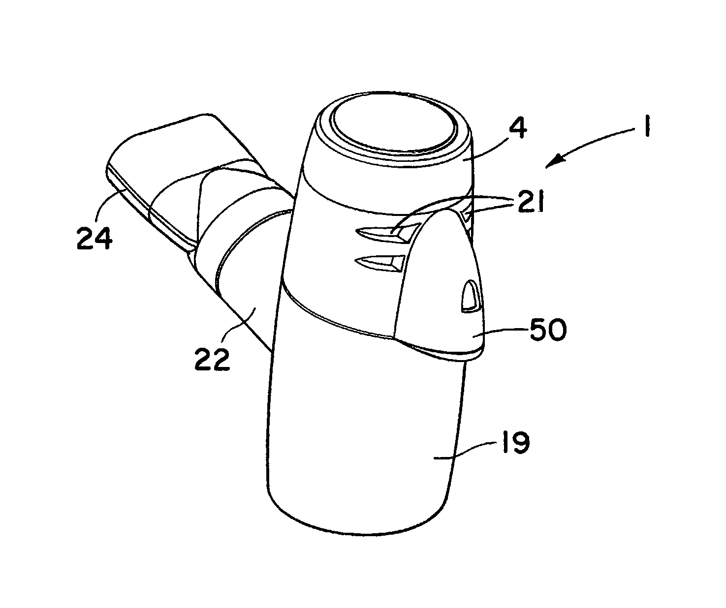
FIG. 1 is a perspective view of a nebuliser according to an embodiment of the invention;
FIG. 2 is a perspective view of a battery driven controller for use with the nebuliser;
FIG. 3 is a perspective view of a mains driven controller for use with the nebuliser;
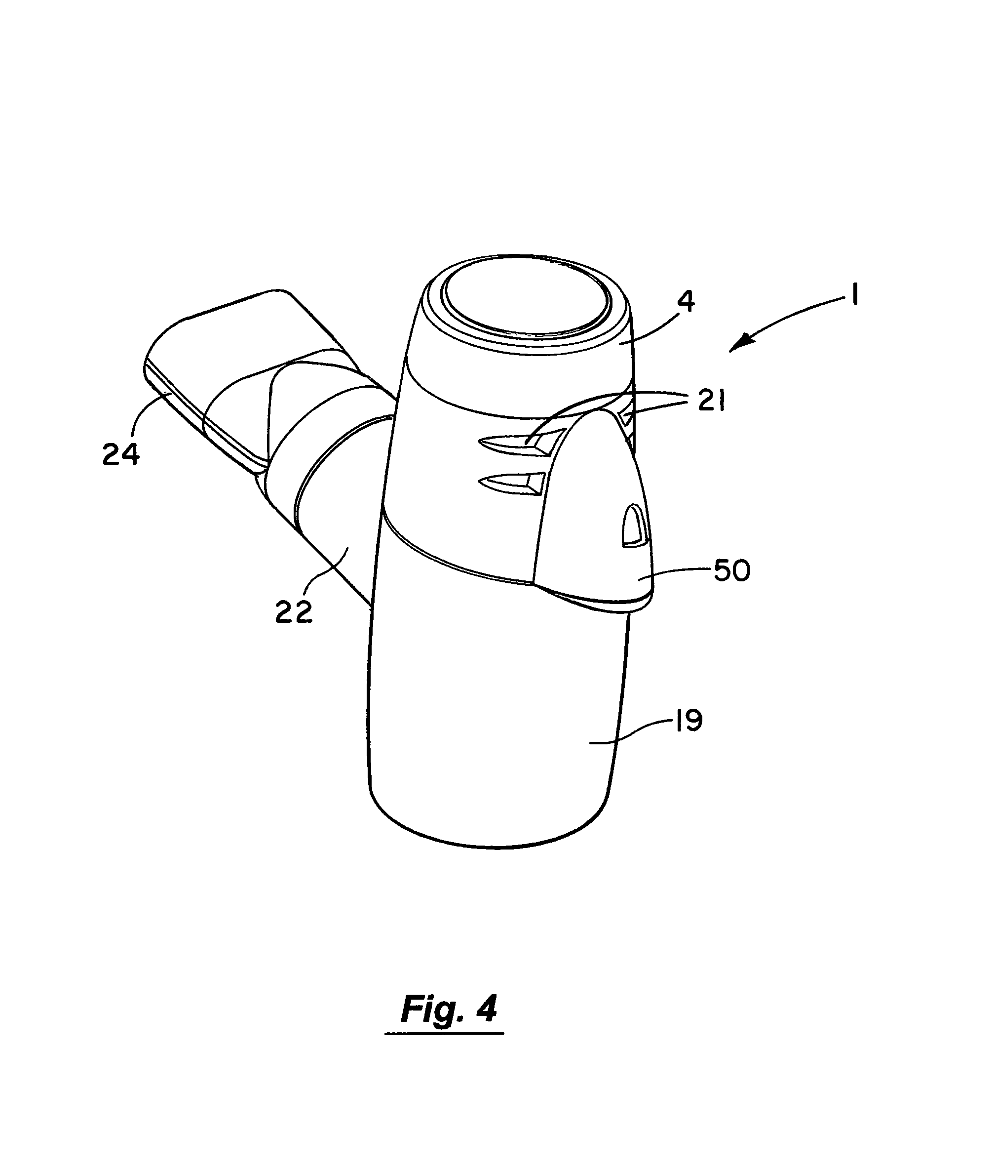
FIG. 4 is a perspective view of a nebuliser according to an embodiment of the invention with a mouth piece fitted;
FIG. 5 is a cut-away view of the nebuliser of FIG. 4;
FIG. 6 is an exploded view of the nebuliser of FIGS. 4 and 5;
FIG. 7 is a perspective view from above of an upper part of the nebuliser;
FIG. 8 is a perspective view from below of the upper part of the nebuliser;
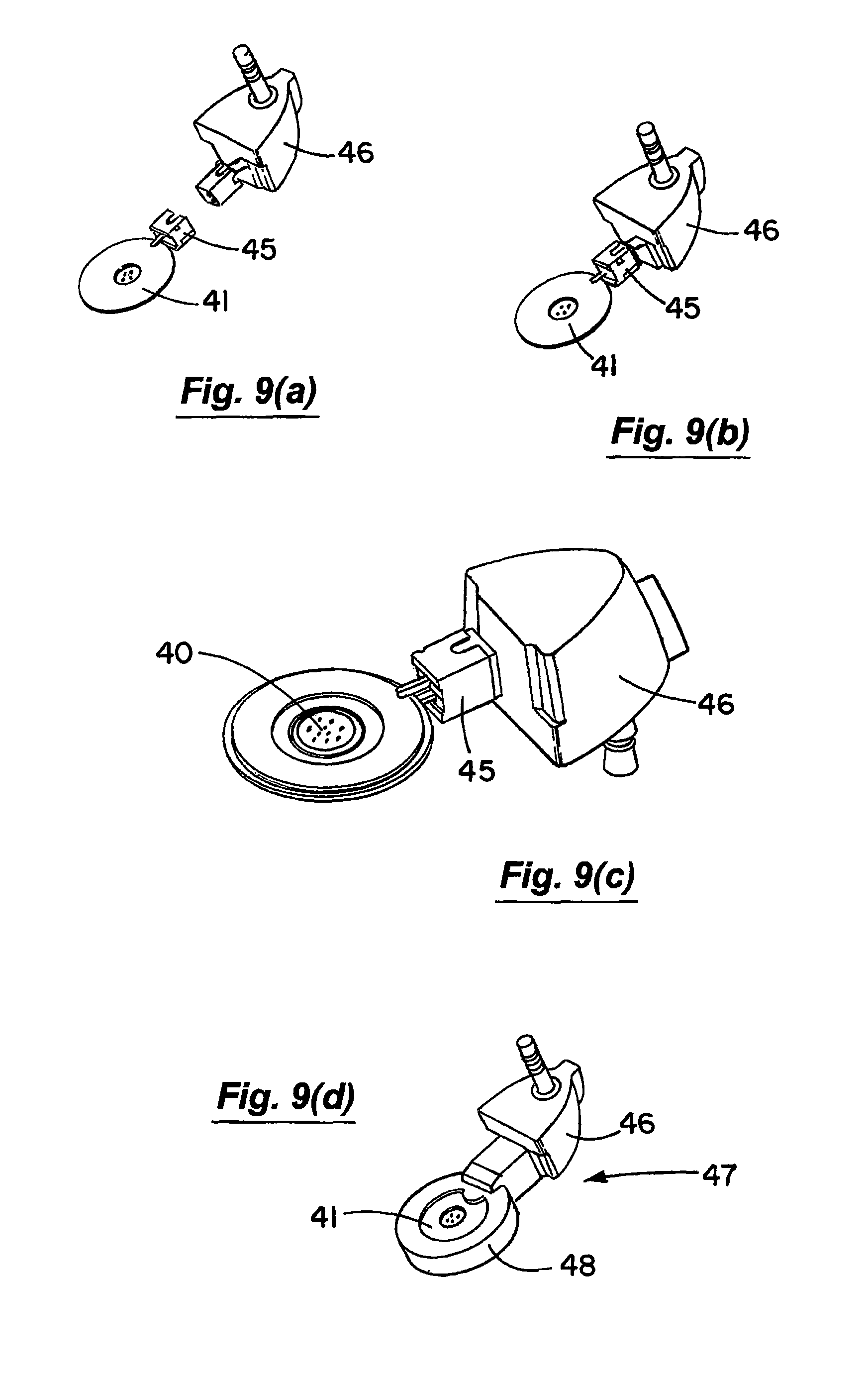
FIGS. 9(a) to 9(d) are perspective views illustrating the mounting and overmoulding of a vibratable member and associated connector for a nebuliser according to an embodiment of the invention;
FIG. 10 is a block diagram of a drive for a piezoelectric element;
FIG. 11 is a circuit diagram of the drive and load stages of FIG. 10;
FIGS. 12(a) to 12(d) are circuit diagrams showing operation of the drive of FIGS. 10 and 11 in four modes labelled mode I to mode 4;
FIGS. 13 to 15 are views similar to FIGS. 4 to 6 of a nebuliser according to an embodiment of the invention that includes a nasal piece fitted;
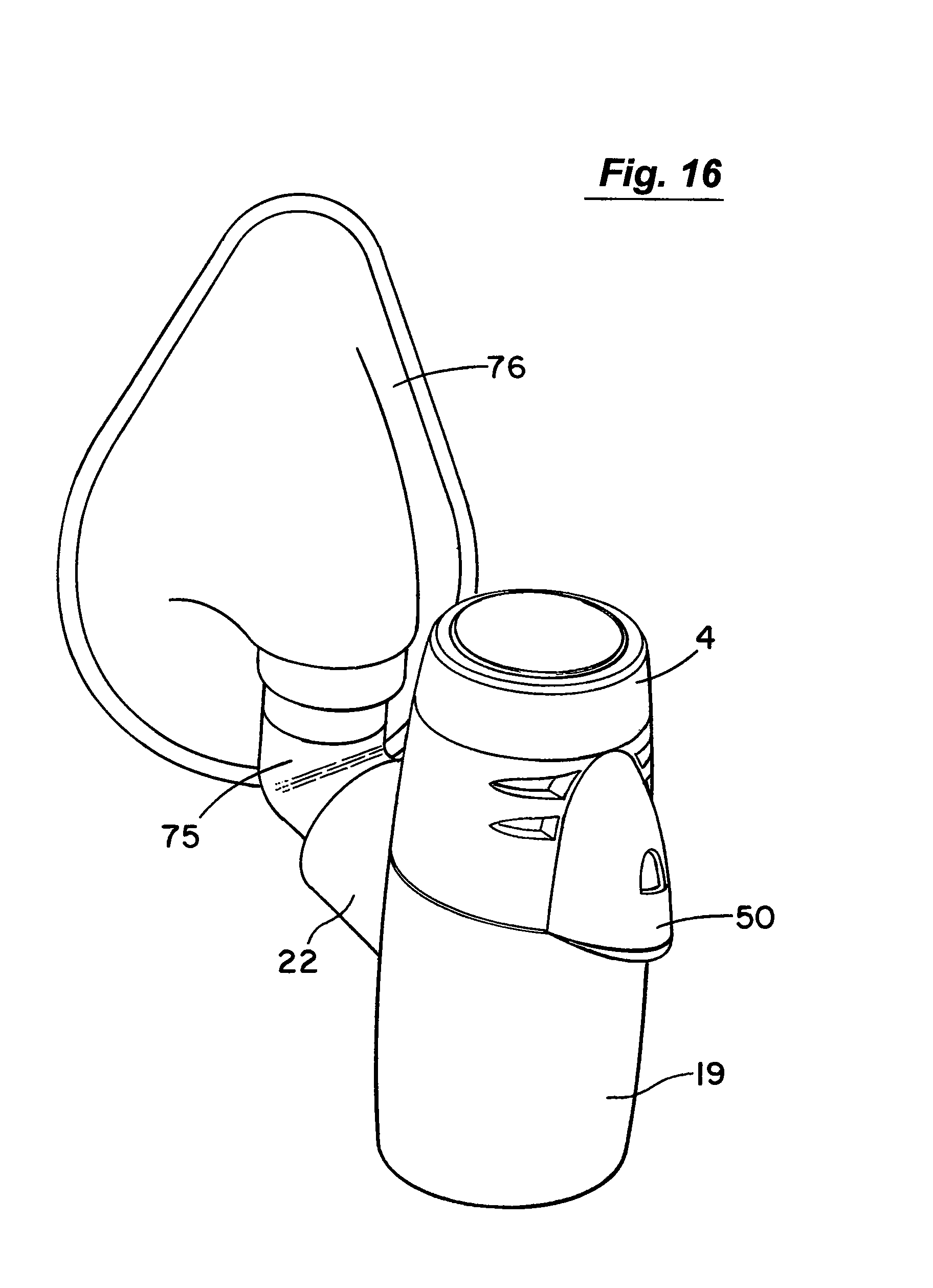
FIGS. 16 to 18 are views similar to FIGS. 4 to 6 of a nebuliser according to an embodiment of the invention with a face mask adaptor fitted; and
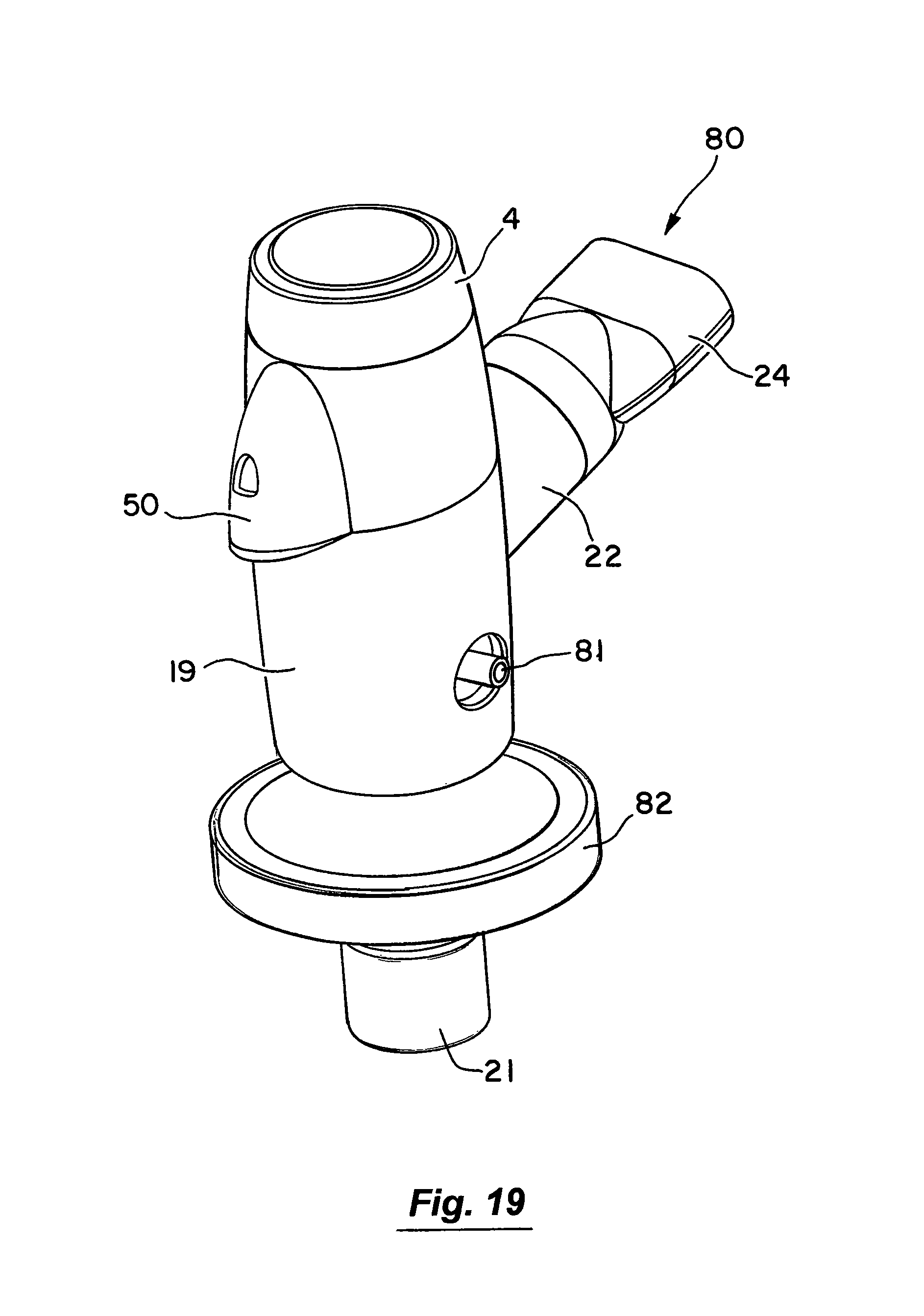
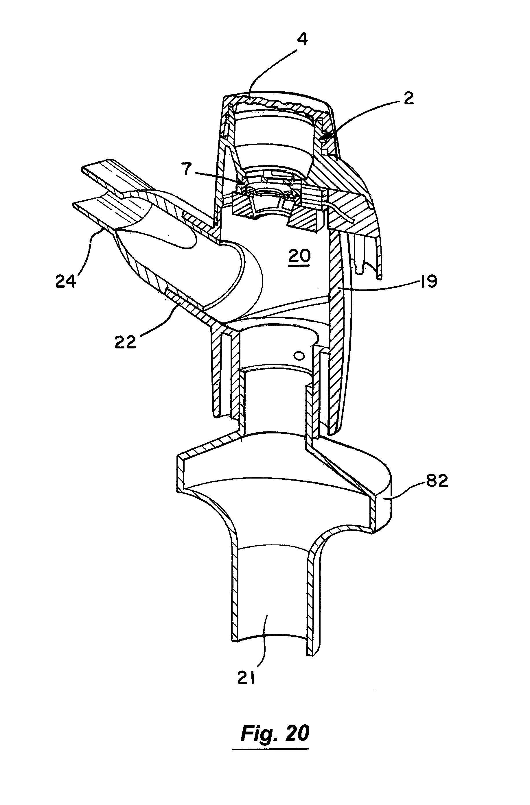
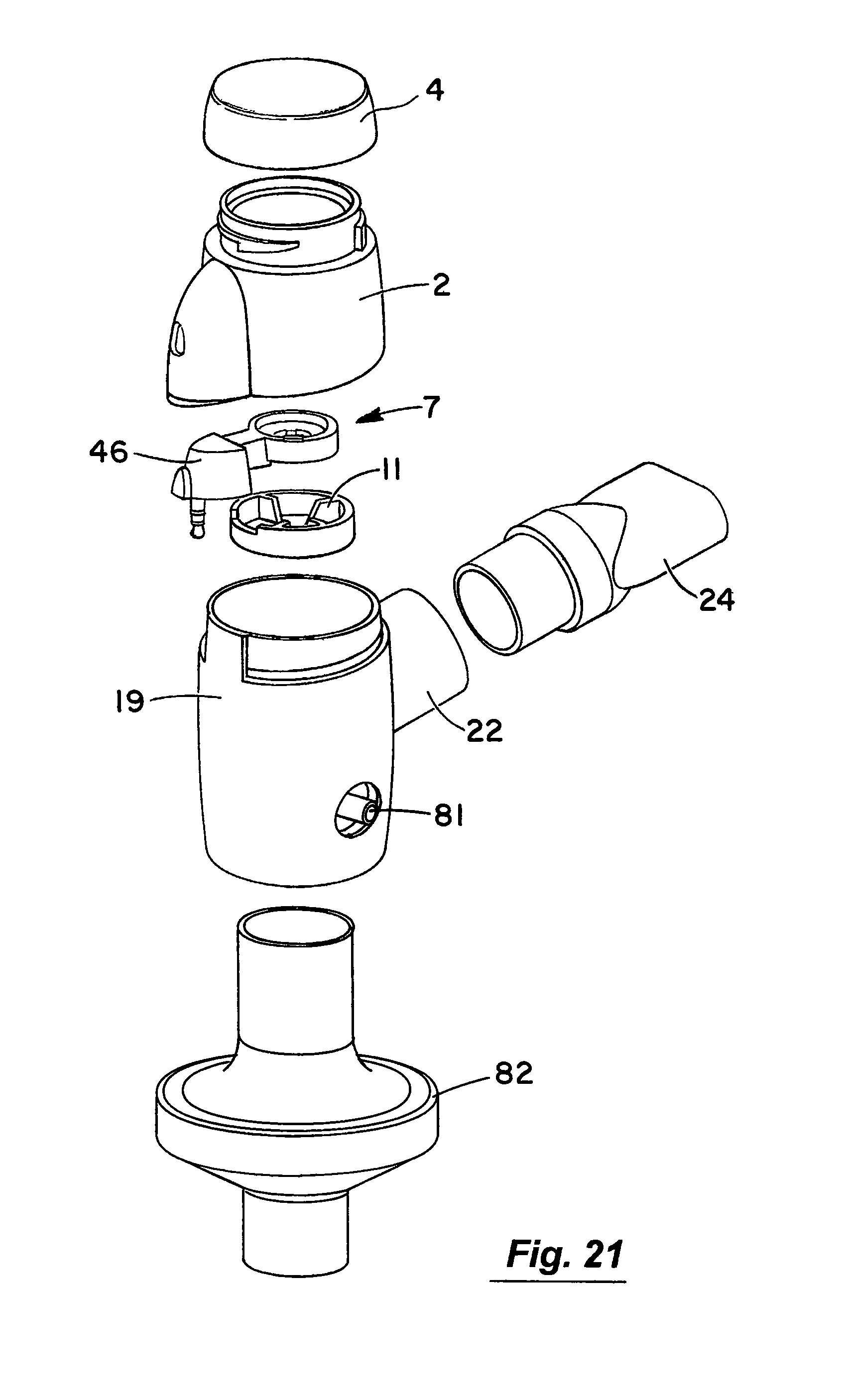
FIGS. 19 to 21 are views similar to FIGS. 4 to 6 of a nebuliser according to another embodiment of the invention.
DETAILED DESCRIPTION OF THE INVENTION
Referring to the drawings and initially to FIGS. 1 to 8 thereof there is illustrated a nebuliser 1 according to an embodiment of the invention for delivery of a medicament to the respiratory system of a patient. The nebuliser 1 comprises a housing having a reservoir, which in this embodiment takes the form of medication cup 2 for liquid medicament. The medication cup 2 has an upper inlet 3 which is covered by a releasable cup 4. The cup 4 is transparent to allow a user to view the contents of the cup. The cup 2 also has a lower outlet to which the medicament flows by gravity. The cup 4 has a lower conical portion 6 to promote the flow of medicament to the outlet. An aerosol generator 7 is mounted at the outlet of the cup to aerosolise the liquid medicament. The aerosol generator 7 is protected against user access from above by a barrier mesh 10 which in this case is integrally formed with the medication cup. The aerosol generator 7 is also protected from below by a lower mesh 11 which is separately formed from the medication cup 2. The protector meshes 10, 11 are particularly apparent from FIGS. 5, 7 and 8.
Aerosol generated by the aerosol generator 7 is delivered into a vented aerosol passage 20 defined by a nebuliser body 19. Air passes into the passage 20 through air inlets 21. The air entrains the aerosolised medicament and the entrained aerosolised medicament is delivered from the nebuliser through an outlet port 22 from the passage 20. In this case the inlets 21 are formed by air vents which are located above the aerosol generator 7. The outlet port 22 has an extension or connector piece 23 which is inclined upwardly to direct flow into a respiratory system. In this case the outlet connector 23 is fitted with a releasable mouthpiece part 24 which is a push-fit on the connector 23.
The nebuliser 1 has a baffle to direct air and entrained aerosolised medicament to the outlet 22. In this case the baffle is formed by a floor 25 of the nebuliser body 19. It will be noted that the baffle 25 is inclined downwardly towards the outlet port 22. The arrangement of the inlet 21 on one side of the nebuliser housing, the outlet 22 on a generally opposite side of the housing and the baffle 25 optimises the flow of air and entrained aerosolised medicament to the outlet 22.
The nebuliser 1 has an aerosol rain-out trap 30 for collecting any larger droplets not entrained in the air. In this case the rain-out trap 30 is between the outlet port 22 and the baffle 25. Any droplets not entrained by the air impinge on the baffle 25 and flow down the incline into the trap 30. Similarly any droplets that may form at the outlet 22 or in the associated connectors are directed to flow into the trap 30. The trap 30 is readily emptied by opening the nebuliser housing and inverting the bottom of the housing.
Typically, the medication cup 2 is configured to accommodate up to about 6 ml to about 10 ml of liquid medicament.
The aerosol generator 7 comprises a vibratable member 40 and a piezoelectric element 41. The vibratable member 40 has a plurality of tapered apertures extending between a first surface and a second surface thereof, as described in U.S. Pat. No. 5,164,740 (the first '740 patent); U.S. Pat. No. 5,586,550 (the '550 patent); U.S. Pat. No. 5,758,637 (the '637 patent); and U.S. Pat. No. 6,085,740 (the second '740 patent), the entire contents of which are incorporated herein by this reference.
The first surface of the vibratable member 40, which in use faces upwardly, receives the liquid medicament from the medication cup 2, and the aerosolised medicament is generated at the second surface of the vibratable member 40 by ejecting droplets of medicament upon vibration of the member 40. In use the second surface faces downwardly. In one case, the apertures in the vibratable member 40 may be sized to produce an aerosol in which about 70% or more of the droplets by weight have a size in the range from about 1 to about 5 micrometers. In another embodiment, about 70% or more (by weight) of the droplets have sizes ranging from about 1 to about 6 micrometers.
The vibratable member 40 is non-planer, and is preferably dome-shaped in geometry.
The piezoelectric element 41 has an electrical connection socket 45 to which a connector plug element 46 is mounted as illustrated in FIGS. 9(a) and 9(b). The piezoelectric element 41 and the connection 45 and plug 46 is then overmoulded to form a sub-assembly 47 which defines a housing 48 for the piezoelectric element 41. The sub-assembly 47 is mounted in the nebuliser housing as illustrated.
The apparatus 1 also includes a controller as illustrated, to control operation of and to supply power to the aerosol generator 7. The plug element 46 defines a signal interface port 50 fixed to the nebuliser housing to receive a control signal from the controller. The controller may be connected to the signal interface port 50 by means of a control lead 52, which has a docking member 51 or connector for mating with the plug 46 at the interface port 50. A control signal and power may be passed from the controller through the lead 52 to the aerosol generator 7 to control the operation of and supply power to the aerosol generator 7.
As illustrated in FIG. 2 in one case a controller 55 may comprise a battery operated unit.
Alternatively, a controller 56 may have a mains plug 57 for connecting directly to a mains power source. In this case the controller has an integral AC-DC circuit as well as control circuitry mounted in a single housing.
Each controller 55 or 56 has a housing 60 and a user interface to selectively control operation of the aerosol generator 7. The user interface may be in the form of, for example, an on-off button 58.
Status indication means are also provided on the housing 60 to indicate the operational state of the aerosol generator 7. For example, the status indication means may be in the form of a visible LED 61, to indicate an operational state of the aerosol generator 7.
Referring to FIGS. 10 to 12 the piezo drive arrangement is illustrated. Power may be from an AC/DC power supply or a DC/DC power supply, in what is illustrated as a Stage 1. Where the former a V.sub.bus level of 20V is provided by a universal input (85 V.sub.ac-264 V.sub.ac) AC/DC adapter. Where the latter, batteries may provide the power.
In a Stage 2 a push/pull resonant circuit provides the following output to the load: P.sub.out=1 W f.sub.out=128 kHz V.sub.out=54 V.sub.ms
The resonant circuit comprises a resonant inductor L.sub.res and the capacitive element (C.sub.p) of the piezoelectric load, driven by two MOSFETs Q1 and Q2 in a push-pull arrangement. As shown in FIG. 11 the resonant circuit also comprises a 100 .mu.F bulk capacitor C.sub.bus and a DC blocking capacitor C.sub.dc.
Referring particularly to FIGS. 12(a) to 12(d) switching period modes Mode 1 to Mode 4, respectively, are illustrated. Mode 1 C.sub.dc is neglected because its AC ripple is assumed negligible. Q1 turned on, Q2 turned off. Positive current flow in direction of arrow. Mode equations solved using equation: V.sub.bus=V.sub.Lres+V.sub.Cp(t) Mode 2 Q1 turning off, Q2 off. Current freewheels through anti-parallel diode of Q2. Mode equation: V.sub.Lres(t)+V.sub.Cp(t)+V.sub.DQ2=0 Mode 3 Q1 turned off, Q2 turned on. Positive current flow in direction of arrow. Mode equation: V.sub.Lres(t)+V.sub.cp(t)=0 Mode 4 Q2 turning off, Q1 off. Current freewheels through anti-parallel diode of Q1. Mode equation: V.sub.Cp(t)+V.sub.Lres(t)-V.sub.DQI-V.sub.Cbus=0
In use, the cap 4 is opened and medicament is delivered through the inlet port 3 into the medication cup 2. Typically a supply container, such as a nebule or a syringe, is used to deliver the liquid medicament through the inlet port 3 into the medication cup 2. The liquid medicament in the medication cup 2 flows by gravitational action towards the aerosol generator 7 at the lower medicament outlet.
By distancing the inlet port 11 to the reservoir 2 from the aerosol generator 3 at the outlet 16, this arrangement creates a sterile barrier between the delivery of the liquid medicament into medication cup 2 and the respiratory system of the patient.
The docking member of the control lead 52 is mated with the signal interface port 50 on the reservoir 2 to connect the controller 55 or 56 to the aerosol generator 7. The controller 50 may then be activated to supply power and a control signal to the aerosol generator 7, which causes the piezoelectric element 41 to vibrate the vibratable member 40.
This vibration of the vibratable member 40 causes the liquid medicament at the top surface of the member 40 to pass through the apertures to the lower surface where the medicament is aerosolised by the ejection of small droplets of medicament.
The aerosolised medicament passes from the aerosol generator 7 into the passage 20 of the housing 19. The aerosolised medicament is entrained with a gas, such as air, which passes into the passage 20 through the inlet 21. The entrained mixture of the aerosolised medicament and the gas then passes out through the outlet 22 and on to the respiratory system of the patient.
In this case, the mouthpiece 24 is gripped between the teeth of the user, with the lips sealed around the mouthpiece. The user breathes in and out slowly. On the exhale cycle, exhaled gas flows back along the mouthpiece and into the passage 20. Exhaust may pass through the gas inlets 21. Breathing is continued in this way until aerosol formation has stopped indicating that all the medicament in the medication cup 2 has been delivered into the patients respiratory system. The nebuliser is turned off by pressing the on/off button 58.
A suitable material for the various connectors and housings is ABS. An alternative material for the various connectors and housings is polycarbonate or polysulphone. By manufacturing these components of the apparatus from polysulphone or polycarbonate, this enables these components to be autoclaved for multiple use of the same apparatus.
Referring now to FIGS. 13 to 15 there is illustrated a nebuliser as described above with a nasal piece 70 attached. The nasal piece 70 is used to deliver the medicament through the users nose.
Referring now to FIGS. 16 to 18 there is illustrated a nebuliser as described above which in this case has an elbow connector 75 for connection to a face mask 76.
Referring to FIGS. 19 to 20 there is illustrated another nebuliser 80 which is similar in some respects to the nebulisers described above and like parts we assigned the same reference numerals. In this case air is supplemented by an oxygen supply which is connected through an inlet port 81. A holder 82 is releasably mounted to the nebuliser housing. The holder accepts an external filter which collects all exhaled aerosol. In addition, the holder serves as a diffuser to the jet of gas entering through the inlet port, reducing turbulence and impactive losses of aerosol within the nebuliser housing.
The invention provides a nebuliser which is relatively small, light weight and is easy to use. The controllers are also small and light weight. Aerosol is readily generated and efficiently entrained in a gas flow for ease and-efficiency of patient use without medical supervision. The nebuliser may be tilted significantly from the vertical (by up to 45.degree.) without significantly effecting functionality. Thus, the nebuliser may be easily used by patients whilst sitting down or at least partially lying down. The gravity dependent orientation of the aerosol generator and the internal volume in the nebuliser provided by the chamber increases inhaled mass of aerosol in such a way that cough reflex is inhibited. The inclusion of the filter in a dependent position reduces risk of second hand aerosol exposure.
We have found that delivery of non-newtonian fluids can be aided by sweeping the driving frequency of the piezo across the aperture plates' delivery range. It is thought that the aperture plate alters its mode of vibration depending on the drive frequency. This change of motion applies additional stresses to the fluid which can thin it. The frequency sweep may be achieved by using one of the PWM (pulse width modulation) outputs of the microcontroller and routing this signal to the input of a half bridge or MOSFET driver.
In this method the frequency changes by the resolution of the system clock (in our case it is T.sub.osc/4-20 Mhz crystal/14=5 Mhz. T=1/F.sub.osc=0.2 .mu.sec. So at approx 130 Khz the frequency can change by approx 3 kHz for each step.) The delivery range is about 120 kHz to 135 kHz. The rate of change of the sweep and range may be controlled using software in the micro controller.
The invention is not limited to the embodiments hereinbefore described which may be varied in construction and detail.
The words "comprise," "comprising," "include," "including," and "includes" when used in this specification and in the following claims are intended to specify the presence of stated features, integers, components, or steps, but they do not preclude the presence or addition of one or more other features, integers, components, steps, or groups.
* * * * *
D00000
D00001
D00002
D00003
D00004
D00005
D00006
D00007
D00008
D00009
D00010
D00011
D00012
D00013

D00014

D00015
D00016
D00017
XML
uspto.report is an independent third-party trademark research tool that is not affiliated, endorsed, or sponsored by the United States Patent and Trademark Office (USPTO) or any other governmental organization. The information provided by uspto.report is based on publicly available data at the time of writing and is intended for informational purposes only.
While we strive to provide accurate and up-to-date information, we do not guarantee the accuracy, completeness, reliability, or suitability of the information displayed on this site. The use of this site is at your own risk. Any reliance you place on such information is therefore strictly at your own risk.
All official trademark data, including owner information, should be verified by visiting the official USPTO website at www.uspto.gov. This site is not intended to replace professional legal advice and should not be used as a substitute for consulting with a legal professional who is knowledgeable about trademark law.