Position sensitive suspension damping with an active valve
Cox , et al. April 19, 2
U.S. patent number 11,306,798 [Application Number 16/175,656] was granted by the patent office on 2022-04-19 for position sensitive suspension damping with an active valve. This patent grant is currently assigned to Fox Factory, Inc.. The grantee listed for this patent is Fox Factory, Inc.. Invention is credited to Christopher Paul Cox, Everet Owen Ericksen, John Marking.


View All Diagrams
| United States Patent | 11,306,798 |
| Cox , et al. | April 19, 2022 |
Position sensitive suspension damping with an active valve
Abstract
Methods and apparatus for position sensitive dampening with an active valve. In one aspect a fluid damper is provided comprising a damper chamber divided by a piston into a primary compression and a primary rebound chamber; a secondary compression chamber in fluid communication with the damper chamber; and an active valve controlling fluid flow out of the secondary compression chamber.
| Inventors: | Cox; Christopher Paul (Capitola, CA), Marking; John (El Cajon, CA), Ericksen; Everet Owen (Santa Cruz, CA) | ||||||||||
|---|---|---|---|---|---|---|---|---|---|---|---|
| Applicant: |
|
||||||||||
| Assignee: | Fox Factory, Inc. (Duluth,
GA) |
||||||||||
| Family ID: | 67058081 | ||||||||||
| Appl. No.: | 16/175,656 | ||||||||||
| Filed: | October 30, 2018 |
Prior Publication Data
| Document Identifier | Publication Date | |
|---|---|---|
| US 20190203798 A1 | Jul 4, 2019 | |
Related U.S. Patent Documents
| Application Number | Filing Date | Patent Number | Issue Date | ||
|---|---|---|---|---|---|
| 16105639 | Aug 20, 2018 | ||||
| 16042563 | Jul 23, 2018 | ||||
| 15275078 | Aug 7, 2018 | 10040329 | |||
| 15056940 | Aug 21, 2018 | 10054185 | |||
| 14466831 | Sep 27, 2016 | 9452654 | |||
| 14251446 | Aug 14, 2018 | 10047817 | |||
| 14022030 | Apr 5, 2016 | 9303712 | |||
| 13934067 | Aug 28, 2018 | 10060499 | |||
| 13843704 | May 19, 2015 | 9033122 | |||
| 13485401 | May 31, 2012 | ||||
| 13189216 | Jan 19, 2016 | 9239090 | |||
| 13175244 | Jan 14, 2014 | 8627932 | |||
| 13010697 | Oct 14, 2014 | 8857580 | |||
| 12684072 | Jan 7, 2010 | ||||
| 14022030 | |||||
| 12463927 | Oct 8, 2013 | 8550223 | |||
| 61709041 | Oct 2, 2012 | ||||
| 61667327 | Jul 2, 2012 | ||||
| 61645465 | May 10, 2012 | ||||
| 61491858 | May 31, 2011 | ||||
| 61361127 | Jul 2, 2010 | ||||
| 61296826 | Jan 20, 2010 | ||||
| 61143152 | Jan 7, 2009 | ||||
| 61052150 | May 9, 2008 | ||||
| Current U.S. Class: | 1/1 |
| Current CPC Class: | B60G 13/08 (20130101); B60G 17/08 (20130101); F16F 9/48 (20130101); F16F 9/18 (20130101); F16F 9/3214 (20130101); F16F 9/49 (20130101); B60G 2202/24 (20130101); B60G 2500/114 (20130101); F16F 9/19 (20130101); B60G 2500/112 (20130101); F16F 9/3242 (20130101); B60G 2206/41 (20130101) |
| Current International Class: | F16F 9/48 (20060101); B60G 17/08 (20060101); F16F 9/49 (20060101); F16F 9/18 (20060101); F16F 9/32 (20060101); B60G 13/08 (20060101); F16F 9/19 (20060101) |
References Cited [Referenced By]
U.S. Patent Documents
| 435995 | September 1890 | Dunlop |
| 1078060 | November 1913 | Newman |
| 1307502 | June 1919 | Martin |
| 1409849 | March 1922 | Haeberlein |
| 1468652 | September 1923 | Storey et al. |
| 1492731 | May 1924 | Kerr |
| 1560477 | November 1925 | Kessler |
| 1571788 | February 1926 | Bramlette, Jr. |
| 1575973 | March 1926 | Coleman |
| 1655786 | January 1928 | Guerritore et al. |
| 1923011 | August 1933 | Moulton |
| 1948600 | February 1934 | Templeton |
| 1970239 | August 1934 | Klaas |
| 2018312 | October 1935 | Moulton |
| 2098119 | November 1937 | White |
| 2115072 | April 1938 | Hunt et al. |
| 2122407 | July 1938 | Chisholm |
| 2186266 | January 1940 | Henry |
| 2259437 | October 1941 | Dean |
| 2354340 | July 1944 | Utter |
| 2363867 | November 1944 | Isely |
| 2492331 | December 1949 | Spring |
| 2518553 | August 1950 | Kieber |
| 2540525 | February 1951 | Howarth et al. |
| 2559633 | July 1951 | Maurice et al. |
| 2588520 | March 1952 | Halgren et al. |
| 2697600 | December 1954 | Gregoire |
| 2705119 | March 1955 | Ingwer |
| 2725076 | November 1955 | Hansen et al. |
| 2729308 | January 1956 | Koski et al. |
| 2778378 | January 1957 | Presnell |
| 2784962 | March 1957 | Sherburne |
| 2809722 | October 1957 | Smith |
| 2838140 | June 1958 | Rasmusson et al. |
| 2846028 | August 1958 | Gunther |
| 2853974 | September 1958 | Hewitt |
| 2879971 | March 1959 | Demay |
| 2883181 | April 1959 | Hogan et al. |
| 2897613 | August 1959 | Davidson et al. |
| 2924304 | February 1960 | Patriquin |
| 2941629 | June 1960 | Etienne et al. |
| 2967065 | January 1961 | Schwendner |
| 2973744 | March 1961 | Hennells |
| 2991804 | July 1961 | Merkle |
| 3003595 | October 1961 | Patriquin et al. |
| 3056598 | October 1962 | Sutton Ransom et al. |
| 3073586 | January 1963 | Hartel et al. |
| 3074709 | January 1963 | Ellis et al. |
| 3085530 | April 1963 | Williamson |
| 3087583 | April 1963 | Bruns |
| 3107753 | October 1963 | Georgette et al. |
| 3127958 | April 1964 | Szostak |
| 3175645 | March 1965 | Schafer et al. |
| 3202413 | August 1965 | Colmerauer |
| 3206153 | September 1965 | Burke |
| 3238850 | March 1966 | Desmarchelier |
| 3284076 | November 1966 | Gibson |
| 3286797 | November 1966 | Leibfritz et al. |
| 3405625 | October 1968 | Carlson et al. |
| 3419849 | December 1968 | Anderson et al. |
| 3420493 | January 1969 | Kraft et al. |
| 3447644 | June 1969 | Duckett |
| 3494606 | February 1970 | Hanchen |
| 3528700 | September 1970 | Janu et al. |
| 3537722 | November 1970 | Moulton |
| 3556137 | January 1971 | Billeter et al. |
| 3559027 | January 1971 | Arsem |
| 3560033 | February 1971 | Barkus |
| 3575442 | April 1971 | Elliott et al. |
| 3584331 | June 1971 | Richard et al. |
| 3603575 | September 1971 | Arlasky et al. |
| 3605960 | September 1971 | Singer |
| 3618972 | November 1971 | Buhl |
| 3621950 | November 1971 | Lutz |
| 3650033 | March 1972 | Behne et al. |
| 3701544 | October 1972 | Stankovich |
| 3714953 | February 1973 | Solvang |
| 3750856 | August 1973 | Kenworthy et al. |
| 3784228 | January 1974 | Hoffmann et al. |
| 3791408 | February 1974 | Saitou et al. |
| 3792644 | February 1974 | Ferguson et al. |
| 3795291 | March 1974 | Naito et al. |
| 3830482 | August 1974 | Norris |
| 3842753 | October 1974 | Ross et al. |
| 3861487 | January 1975 | Gill |
| 3903613 | September 1975 | Bisberg |
| 3941402 | March 1976 | Jankowski et al. |
| 3974910 | August 1976 | Papai |
| 3981204 | September 1976 | Starbard et al. |
| 3981479 | September 1976 | Foster et al. |
| 3986118 | October 1976 | Madigan |
| 3995883 | December 1976 | Glaze |
| 4022113 | May 1977 | Blatt et al. |
| 4032829 | June 1977 | Schenavar et al. |
| 4036335 | July 1977 | Thompson et al. |
| 4045008 | August 1977 | Bauer |
| 4072087 | February 1978 | Mueller et al. |
| 4103881 | August 1978 | Simich |
| 4106522 | August 1978 | Manesse |
| 4114735 | September 1978 | Kato |
| 4121610 | October 1978 | Harms et al. |
| 4131657 | December 1978 | Ball et al. |
| 4139186 | February 1979 | Postema et al. |
| 4153237 | May 1979 | Supalla |
| 4159106 | June 1979 | Nyman et al. |
| 4166612 | September 1979 | Freitag et al. |
| 4174098 | November 1979 | Baker et al. |
| 4183509 | January 1980 | Nishikawa et al. |
| 4236613 | December 1980 | Van Der Lely |
| 4287812 | September 1981 | Iizumi |
| 4291850 | September 1981 | Sharples |
| 4305566 | December 1981 | Grawunde |
| 4311302 | January 1982 | Heyer et al. |
| 4333668 | June 1982 | Hendrickson et al. |
| 4334711 | June 1982 | Mazur et al. |
| 4337850 | July 1982 | Shimokura et al. |
| 4348016 | September 1982 | Milly |
| 4351515 | September 1982 | Yoshida |
| 4366969 | January 1983 | Benya et al. |
| 4387781 | June 1983 | Ezell et al. |
| 4437548 | March 1984 | Ashiba et al. |
| 4465299 | August 1984 | Stone et al. |
| 4474363 | October 1984 | Numazawa et al. |
| 4491207 | January 1985 | Boonchanta et al. |
| 4500827 | February 1985 | Merritt et al. |
| 4502673 | March 1985 | Clark et al. |
| 4529180 | July 1985 | Hill |
| 4546959 | October 1985 | Tanno |
| 4548233 | October 1985 | Wolfges |
| 4570851 | February 1986 | Cirillo et al. |
| 4572317 | February 1986 | Isono et al. |
| 4620619 | November 1986 | Emura et al. |
| 4624346 | November 1986 | Katz et al. |
| 4630818 | December 1986 | Saarinen |
| 4634142 | January 1987 | Woods et al. |
| 4647068 | March 1987 | Asami et al. |
| 4655440 | April 1987 | Eckert |
| 4657280 | April 1987 | Ohmori et al. |
| 4659104 | April 1987 | Tanaka et al. |
| 4660689 | April 1987 | Hayashi et al. |
| 4673194 | June 1987 | Sugasawa |
| 4696489 | September 1987 | Fujishiro et al. |
| 4709779 | December 1987 | Takehara |
| 4723753 | February 1988 | Torimoto |
| 4729459 | March 1988 | Inagaki et al. |
| 4732244 | March 1988 | Verkuylen |
| 4743000 | May 1988 | Karnopp |
| 4744444 | May 1988 | Gillingham |
| 4750735 | June 1988 | Furgerson et al. |
| 4765648 | August 1988 | Mander et al. |
| 4773671 | September 1988 | Inagaki |
| 4786034 | November 1988 | Heess et al. |
| 4806082 | February 1989 | Schenk |
| 4815575 | March 1989 | Murty et al. |
| 4821852 | April 1989 | Yokoya |
| 4826207 | May 1989 | Yoshioka et al. |
| 4830395 | May 1989 | Foley |
| 4836578 | June 1989 | Soltis |
| 4838306 | June 1989 | Horn et al. |
| 4838394 | June 1989 | Lemme et al. |
| 4846317 | July 1989 | Hudgens |
| 4858733 | August 1989 | Noguchi et al. |
| 4919166 | April 1990 | Sims et al. |
| 4936423 | June 1990 | Karnopp |
| 4936424 | June 1990 | Costa |
| 4938228 | July 1990 | Righter |
| 4949262 | August 1990 | Buma et al. |
| 4949989 | August 1990 | Kakizaki et al. |
| 4958706 | September 1990 | Richardson et al. |
| 4975849 | December 1990 | Ema et al. |
| 4984819 | January 1991 | Kakizaki et al. |
| 4986393 | January 1991 | Preukschat et al. |
| 5027303 | June 1991 | Witte |
| 5031455 | July 1991 | Cline |
| 5036934 | August 1991 | Nishina et al. |
| 5040381 | August 1991 | Hazen |
| 5044614 | September 1991 | Rau |
| 5060910 | October 1991 | Iwata |
| 5060959 | October 1991 | Davis et al. |
| 5072812 | December 1991 | Imaizumi |
| 5074624 | December 1991 | Stauble et al. |
| 5076404 | December 1991 | Gustafsson |
| 5080392 | January 1992 | Bazergui |
| 5094325 | March 1992 | Smith |
| 5105918 | April 1992 | Hagiwara et al. |
| 5113980 | May 1992 | Furrer et al. |
| 5152547 | October 1992 | Davis |
| 5161653 | November 1992 | Hare |
| 5163742 | November 1992 | Topfer et al. |
| 5178242 | January 1993 | Nakamura et al. |
| 5186481 | February 1993 | Turner |
| 5203584 | April 1993 | Butsuen et al. |
| 5207774 | May 1993 | Wolfe et al. |
| 5230364 | July 1993 | Leng et al. |
| 5231583 | July 1993 | Lizell |
| 5236169 | August 1993 | Johnsen et al. |
| 5246247 | September 1993 | Runkel |
| 5248014 | September 1993 | Ashiba |
| 5259487 | November 1993 | Petek et al. |
| 5263559 | November 1993 | Mettner |
| 5265902 | November 1993 | Lewis |
| 5275086 | January 1994 | Stallings, Jr. |
| 5277283 | January 1994 | Yamaoka et al. |
| 5283733 | February 1994 | Colley |
| 5284330 | February 1994 | Carlson et al. |
| 5293971 | March 1994 | Kanari |
| 5295074 | March 1994 | Williams |
| 5295563 | March 1994 | Bennett |
| 5297045 | March 1994 | Williams et al. |
| 5307907 | May 1994 | Nakamura et al. |
| 5311709 | May 1994 | Kobori et al. |
| 5318066 | June 1994 | Burgorf et al. |
| 5328004 | July 1994 | Fannin et al. |
| 5346242 | September 1994 | Karnopp |
| 5347186 | September 1994 | Konotchick et al. |
| 5348112 | September 1994 | Vaillancourt |
| 5372223 | December 1994 | Dekock et al. |
| 5372224 | December 1994 | Samonil et al. |
| 5381952 | January 1995 | Duprez |
| 5390949 | February 1995 | Naganathan et al. |
| 5392885 | February 1995 | Patzenhauer et al. |
| 5396973 | March 1995 | Schwemmer et al. |
| 5398787 | March 1995 | Woessner et al. |
| 5413196 | May 1995 | Forster |
| 5467280 | November 1995 | Kimura |
| 5480011 | January 1996 | Nagai et al. |
| 5485417 | January 1996 | Wolf et al. |
| 5487006 | January 1996 | Kakizaki et al. |
| 5503258 | April 1996 | Clarke et al. |
| 5517898 | May 1996 | Kim et al. |
| 5542150 | August 1996 | Tu |
| 5551674 | September 1996 | Johnsen |
| 5553836 | September 1996 | Ericson |
| 5578877 | November 1996 | Tiemann |
| 5588510 | December 1996 | Wilke |
| 5592401 | January 1997 | Kramer |
| 5597180 | January 1997 | Ganzel et al. |
| 5598337 | January 1997 | Butsuen et al. |
| 5601164 | February 1997 | Ohsaki et al. |
| 5611413 | March 1997 | Feigel |
| 5634563 | June 1997 | Peng |
| 5651433 | July 1997 | Wirth et al. |
| 5657840 | August 1997 | Lizell |
| 5687575 | November 1997 | Keville et al. |
| 5697477 | December 1997 | Hiramoto et al. |
| 5699885 | December 1997 | Forster |
| 5722645 | March 1998 | Reitter |
| 5803443 | September 1998 | Chang |
| 5806159 | September 1998 | Ohnishi et al. |
| 5810128 | September 1998 | Eriksson et al. |
| 5810384 | September 1998 | Iwasaki et al. |
| 5813456 | September 1998 | Milner et al. |
| 5813731 | September 1998 | Newman et al. |
| 5816281 | October 1998 | Mixon |
| 5818132 | October 1998 | Konotchick et al. |
| 5826935 | October 1998 | Defreitas et al. |
| 5828843 | October 1998 | Samuel et al. |
| 5829733 | November 1998 | Becker |
| 5833036 | November 1998 | Gillespie |
| 5850352 | December 1998 | Moezzi et al. |
| 5850896 | December 1998 | Tanaka |
| 5853071 | December 1998 | Robinson |
| 5872418 | February 1999 | Wischnewskiy |
| 5884921 | March 1999 | Katsuda et al. |
| 5937975 | August 1999 | Forster |
| 5947238 | September 1999 | Jolly et al. |
| 5952823 | September 1999 | Sprecher et al. |
| 5954318 | September 1999 | Kluhsman |
| 5956951 | September 1999 | O''Callaghan |
| 5957252 | September 1999 | Berthold |
| 5971116 | October 1999 | Franklin |
| 5987368 | November 1999 | Kamimae et al. |
| 5988330 | November 1999 | Morris |
| 5988655 | November 1999 | Sakai et al. |
| 5992450 | November 1999 | Parker et al. |
| 5996745 | December 1999 | Jones et al. |
| 5996746 | December 1999 | Turner et al. |
| 5999868 | December 1999 | Beno et al. |
| 6000702 | December 1999 | Streiter |
| 6013007 | January 2000 | Root et al. |
| 6017047 | January 2000 | Hoose |
| 6029958 | February 2000 | Larsson et al. |
| 6035979 | March 2000 | Forster |
| 6050583 | April 2000 | Bohn |
| 6058340 | May 2000 | Uchiyama et al. |
| 6067490 | May 2000 | Ichimaru et al. |
| 6073536 | June 2000 | Campbell |
| 6073700 | June 2000 | Tsuji et al. |
| 6073736 | June 2000 | Franklin |
| 6092011 | July 2000 | Hiramoto et al. |
| 6092816 | July 2000 | Sekine et al. |
| 6105988 | August 2000 | Turner et al. |
| 6112868 | September 2000 | Graham et al. |
| 6120049 | September 2000 | Gonzalez et al. |
| 6131709 | October 2000 | Jolly et al. |
| 6135434 | October 2000 | Marking |
| 6141969 | November 2000 | Launchbury et al. |
| 6151930 | November 2000 | Carlson |
| 6152856 | November 2000 | Studor et al. |
| 6157103 | December 2000 | Ohta |
| 6179098 | January 2001 | Hayakawa et al. |
| 6196555 | March 2001 | Gaibler |
| 6199669 | March 2001 | Huang et al. |
| 6203026 | March 2001 | Jones |
| 6213263 | April 2001 | De Frenne |
| 6215217 | April 2001 | Kurosawa et al. |
| 6217049 | April 2001 | Becker |
| 6219045 | April 2001 | Leahy et al. |
| 6244398 | June 2001 | Girvin et al. |
| 6254067 | July 2001 | Yih |
| 6279702 | August 2001 | Koh |
| 6290034 | September 2001 | Ichimaru |
| 6293530 | September 2001 | Delorenzis et al. |
| 6296092 | October 2001 | Marking et al. |
| 6311962 | November 2001 | Marking |
| 6318525 | November 2001 | Vignocchi et al. |
| 6321888 | November 2001 | Reybrouck et al. |
| 6322468 | November 2001 | Wing et al. |
| 6336648 | January 2002 | Bohn |
| 6343807 | February 2002 | Rathbun |
| 6359837 | March 2002 | Tsukamoto et al. |
| 6360857 | March 2002 | Fox et al. |
| 6371262 | April 2002 | Katou et al. |
| 6371267 | April 2002 | Kao et al. |
| 6378816 | April 2002 | Pfister |
| 6378885 | April 2002 | Ellsworth et al. |
| 6382370 | May 2002 | Girvin |
| 6389341 | May 2002 | Davis |
| 6390747 | May 2002 | Commins |
| 6394238 | May 2002 | Rogala |
| 6401883 | June 2002 | Nyce et al. |
| 6412788 | July 2002 | Ichimaru |
| 6415895 | July 2002 | Marking et al. |
| 6418360 | July 2002 | Spivey et al. |
| 6427812 | August 2002 | Crawley et al. |
| 6434460 | August 2002 | Uchino et al. |
| 6446771 | September 2002 | Sintorn et al. |
| 6458060 | October 2002 | Watterson et al. |
| 6460567 | October 2002 | Hansen, III |
| 6467593 | October 2002 | Corradini et al. |
| 6474454 | November 2002 | Matsumoto et al. |
| 6474753 | November 2002 | Rieth et al. |
| 6501554 | December 2002 | Hackney et al. |
| 6502837 | January 2003 | Hamilton et al. |
| 6510929 | January 2003 | Gordan et al. |
| 6520297 | February 2003 | Lumpkin et al. |
| 6527093 | March 2003 | Oliver et al. |
| 6592136 | July 2003 | Becker et al. |
| 6609686 | August 2003 | Malizia |
| 6619615 | September 2003 | Mayr et al. |
| 6623389 | September 2003 | Campagnolo |
| 6648109 | November 2003 | Farr et al. |
| 6659240 | December 2003 | Dernebo |
| 6659241 | December 2003 | Sendrea |
| 6672687 | January 2004 | Nishio |
| 6701234 | March 2004 | Vogelsang et al. |
| 6732033 | May 2004 | Laplante et al. |
| 6755113 | June 2004 | Shih |
| 6782980 | August 2004 | Nakadate |
| 6817454 | November 2004 | Nezu et al. |
| 6837827 | January 2005 | Lee et al. |
| 6840257 | January 2005 | Dario et al. |
| 6853955 | February 2005 | Burrell et al. |
| 6857625 | February 2005 | Loser et al. |
| 6863291 | March 2005 | Miyoshi |
| 6902513 | June 2005 | McClure et al. |
| 6905203 | June 2005 | Kremers et al. |
| 6920951 | July 2005 | Song et al. |
| 6921351 | July 2005 | Hickman et al. |
| 6923853 | August 2005 | Kremers et al. |
| 6935157 | August 2005 | Miller |
| 6952060 | October 2005 | Goldner et al. |
| 6959906 | November 2005 | Hoenig et al. |
| 6959921 | November 2005 | Rose |
| 6966412 | November 2005 | Braswell et al. |
| 6978871 | December 2005 | Holiviers |
| 6978872 | December 2005 | Turner |
| 6991076 | January 2006 | McAndrews |
| 7025367 | April 2006 | McKinnon et al. |
| 7076351 | July 2006 | Hamilton et al. |
| 7128192 | October 2006 | Fox |
| 7128693 | October 2006 | Brown et al. |
| 7135794 | November 2006 | Kuhnel |
| 7147207 | December 2006 | Jordan et al. |
| 7163222 | January 2007 | Becker et al. |
| 7166062 | January 2007 | Watterson et al. |
| 7166064 | January 2007 | Ashby et al. |
| 7204466 | April 2007 | Hsieh |
| 7208845 | April 2007 | Schaefer et al. |
| 7217224 | May 2007 | Thomas |
| 7234574 | June 2007 | Matsunaga et al. |
| 7234575 | June 2007 | Anderfaas et al. |
| 7234680 | June 2007 | Hull et al. |
| 7243763 | July 2007 | Carlson |
| 7255210 | August 2007 | Larsson et al. |
| 7270221 | September 2007 | McAndrews |
| 7270222 | September 2007 | Aymar et al. |
| 7287760 | October 2007 | Quick et al. |
| 7289138 | October 2007 | Foote et al. |
| 7292867 | November 2007 | Werner et al. |
| 7293764 | November 2007 | Fang |
| 7299112 | November 2007 | Laplante et al. |
| 7302961 | December 2007 | Martin et al. |
| 7306206 | December 2007 | Turner |
| 7316406 | January 2008 | Kimura et al. |
| 7325660 | February 2008 | Norgaard et al. |
| 7363129 | April 2008 | Barnicle et al. |
| 7374028 | May 2008 | Fox |
| 7397355 | July 2008 | Tracy |
| 7413062 | August 2008 | Vandewal |
| 7413063 | August 2008 | Davis |
| 7415336 | August 2008 | Burch et al. |
| 7422092 | September 2008 | Hitchcock et al. |
| 7441638 | October 2008 | Hanawa |
| 7469910 | December 2008 | Munster et al. |
| 7484603 | February 2009 | Fox |
| 7490705 | February 2009 | Fox |
| 7513490 | April 2009 | Robertson |
| 7523617 | April 2009 | Colpitts et al. |
| 7558313 | July 2009 | Feher |
| 7558574 | July 2009 | Feher et al. |
| 7566290 | July 2009 | Lee et al. |
| 7569952 | August 2009 | Bono et al. |
| 7581743 | September 2009 | Graney et al. |
| 7591352 | September 2009 | Hanawa |
| 7600616 | October 2009 | Anderfaas et al. |
| 7628259 | December 2009 | Norgaard et al. |
| 7631882 | December 2009 | Hirao et al. |
| 7654369 | February 2010 | Murray et al. |
| 7673936 | March 2010 | Hsu et al. |
| 7684911 | March 2010 | Seifert et al. |
| 7694785 | April 2010 | Nakadate |
| 7694987 | April 2010 | McAndrews |
| 7699753 | April 2010 | Daikeler et al. |
| 7703585 | April 2010 | Fox |
| 7722056 | May 2010 | Inoue et al. |
| 7722069 | May 2010 | Shirai |
| 7726042 | June 2010 | Meschan |
| 7730906 | June 2010 | Kleinert et al. |
| 7736272 | June 2010 | Martens |
| 7764990 | July 2010 | Martikka et al. |
| 7766794 | August 2010 | Oliver et al. |
| 7770701 | August 2010 | Davis |
| 7775128 | August 2010 | Roessingh et al. |
| 7779974 | August 2010 | Timoney et al. |
| 7795711 | September 2010 | Sauciuc et al. |
| 7837213 | November 2010 | Colegrove et al. |
| 7840346 | November 2010 | Huhtala et al. |
| 7841258 | November 2010 | Komatsu et al. |
| 7845602 | December 2010 | Young et al. |
| 7857325 | December 2010 | Copsey et al. |
| 7872764 | January 2011 | Higgins-Luthman et al. |
| 7874567 | January 2011 | Ichida et al. |
| 7901292 | March 2011 | Uhlir et al. |
| 7909348 | March 2011 | Klieber et al. |
| 7927253 | April 2011 | Dibenedei et al. |
| 7931132 | April 2011 | Braun |
| 7931563 | April 2011 | Shaw et al. |
| 7946163 | May 2011 | Gartner |
| 7975814 | July 2011 | Soederdahl |
| 8016349 | September 2011 | Mouri et al. |
| 8021270 | September 2011 | D'Eredita |
| 8042427 | October 2011 | Kawakami et al. |
| 8056392 | November 2011 | Ryan et al. |
| 8069964 | December 2011 | Deferme et al. |
| 8087676 | January 2012 | McIntyre |
| 8091910 | January 2012 | Hara et al. |
| 8104591 | January 2012 | Barefoot et al. |
| 8121757 | February 2012 | Extance et al. |
| 8127900 | March 2012 | Inoue |
| 8136877 | March 2012 | Walsh et al. |
| 8141438 | March 2012 | Roessingh et al. |
| 8151952 | April 2012 | Lenz et al. |
| 8191964 | June 2012 | Hsu et al. |
| 8201476 | June 2012 | Tsumiyama |
| 8210106 | July 2012 | Tai et al. |
| 8210330 | July 2012 | Vandewal |
| 8246065 | August 2012 | Kodama et al. |
| 8256587 | September 2012 | Bakke et al. |
| 8256732 | September 2012 | Young et al. |
| 8262058 | September 2012 | Kot |
| 8262062 | September 2012 | Kamo et al. |
| 8262100 | September 2012 | Thomas |
| 8265825 | September 2012 | Kajino et al. |
| 8285447 | October 2012 | Bennett et al. |
| 8286982 | October 2012 | Plantet et al. |
| 8291889 | October 2012 | Shafer et al. |
| 8292274 | October 2012 | Adoline et al. |
| 8307965 | November 2012 | Foster et al. |
| 8308124 | November 2012 | Hsu |
| 8317261 | November 2012 | Walsh et al. |
| 8328454 | December 2012 | McAndrews et al. |
| 8336683 | December 2012 | McAndrews et al. |
| 8393446 | March 2013 | Haugen |
| 8413773 | April 2013 | Anderfaas et al. |
| 8423244 | April 2013 | Proemm et al. |
| 8430770 | April 2013 | Dugan et al. |
| 8458080 | June 2013 | Shirai |
| 8480064 | July 2013 | Talavasek |
| 8550223 | October 2013 | Cox et al. |
| 8550551 | October 2013 | Shirai |
| 8556048 | October 2013 | Maeda et al. |
| 8556049 | October 2013 | Jee |
| 8596663 | December 2013 | Shirai et al. |
| 8616351 | December 2013 | Roessle et al. |
| 8622180 | January 2014 | Wootten et al. |
| 8627932 | January 2014 | Marking |
| 8641073 | February 2014 | Lee et al. |
| 8651251 | February 2014 | Preukschat et al. |
| 8655548 | February 2014 | Ichida et al. |
| 8727947 | May 2014 | Tagliabue |
| 8744699 | June 2014 | Hamaguchi et al. |
| 8752682 | June 2014 | Park et al. |
| 8763770 | July 2014 | Marking |
| 8770357 | July 2014 | Sims et al. |
| 8781680 | July 2014 | Ichida et al. |
| 8781690 | July 2014 | Hara et al. |
| 8814109 | August 2014 | Calendrille et al. |
| 8833786 | September 2014 | Camp et al. |
| 8838335 | September 2014 | Bass et al. |
| 8845496 | September 2014 | Arrasvuori et al. |
| 8857580 | October 2014 | Marking |
| 8868253 | October 2014 | Hashimoto et al. |
| 8888115 | November 2014 | Chubbuck et al. |
| 8935036 | January 2015 | Christensen et al. |
| 8936139 | January 2015 | Galasso et al. |
| 8950771 | February 2015 | Felsl et al. |
| 8955653 | February 2015 | Marking |
| 8967343 | March 2015 | Battlogg et al. |
| 8985594 | March 2015 | Yabumoto |
| 8991571 | March 2015 | Murakami |
| 9033122 | May 2015 | Ericksen et al. |
| 9038791 | May 2015 | Marking |
| 9047778 | June 2015 | Cazanas et al. |
| 9057416 | June 2015 | Talavasek |
| 9073592 | July 2015 | Hsu |
| 9103400 | August 2015 | Becker |
| 9108098 | August 2015 | Galasso et al. |
| 9120362 | September 2015 | Marking |
| 9126647 | September 2015 | Kuo |
| 9140325 | September 2015 | Cox et al. |
| 9157523 | October 2015 | Miki et al. |
| 9186949 | November 2015 | Galasso et al. |
| 9194456 | November 2015 | Laird et al. |
| 9199690 | December 2015 | Watarai |
| 9229712 | January 2016 | Takamoto et al. |
| 9239090 | January 2016 | Marking et al. |
| 9278598 | March 2016 | Galasso et al. |
| 9303712 | April 2016 | Cox |
| 9353818 | May 2016 | Marking |
| 9366307 | June 2016 | Marking |
| 9415659 | August 2016 | Kikuchi et al. |
| 9422018 | August 2016 | Pelot et al. |
| 9422025 | August 2016 | Pezzi et al. |
| 9452654 | September 2016 | Ericksen et al. |
| 9523406 | December 2016 | Galasso et al. |
| 9528565 | December 2016 | Marking |
| 9550405 | January 2017 | Marking et al. |
| 9556925 | January 2017 | Marking |
| 9616728 | April 2017 | Marking |
| 9650094 | May 2017 | Laird et al. |
| 9663181 | May 2017 | Ericksen et al. |
| 9682604 | June 2017 | Cox et al. |
| 9784333 | October 2017 | Marking |
| 9810282 | November 2017 | Roessle et al. |
| 9975598 | May 2018 | Bender et al. |
| 10036443 | July 2018 | Galasso et al. |
| 10040328 | August 2018 | Marking |
| 10040329 | August 2018 | Ericksen et al. |
| 10054185 | August 2018 | Cox |
| 10072724 | September 2018 | Haugen et al. |
| 10086670 | October 2018 | Galasso et al. |
| 10089868 | October 2018 | Hayward |
| 10094443 | October 2018 | Marking |
| 10330171 | June 2019 | Cox et al. |
| 10336148 | July 2019 | Ericksen et al. |
| 10336149 | July 2019 | Ericksen et al. |
| 10406883 | September 2019 | Marking |
| 10415662 | September 2019 | Marking |
| 10443671 | October 2019 | Marking |
| 10697514 | June 2020 | Marking |
| 10718397 | July 2020 | Marking |
| 2001/0017334 | August 2001 | Vincent |
| 2001/0022621 | September 2001 | Squibbs |
| 2001/0030408 | October 2001 | Miyoshi et al. |
| 2001/0042663 | November 2001 | Marking et al. |
| 2001/0055373 | December 2001 | Yamashita |
| 2002/0000352 | January 2002 | Matsumoto et al. |
| 2002/0032508 | March 2002 | Uchino et al. |
| 2002/0045987 | April 2002 | Ohata et al. |
| 2002/0050112 | May 2002 | Koch et al. |
| 2002/0050518 | May 2002 | Roustaei |
| 2002/0053493 | May 2002 | Sintorn et al. |
| 2002/0055422 | May 2002 | Airmet et al. |
| 2002/0063469 | May 2002 | Nishio |
| 2002/0089107 | July 2002 | Koh |
| 2002/0095979 | July 2002 | Shirato et al. |
| 2002/0113347 | August 2002 | Robbins et al. |
| 2002/0121416 | September 2002 | Katayama et al. |
| 2002/0130000 | September 2002 | Lisenker et al. |
| 2002/0130003 | September 2002 | Lisenker et al. |
| 2002/0185581 | December 2002 | Trask et al. |
| 2002/0187867 | December 2002 | Ichida et al. |
| 2003/0001346 | January 2003 | Hamilton et al. |
| 2003/0001358 | January 2003 | Becker et al. |
| 2003/0034697 | February 2003 | Goldner et al. |
| 2003/0040348 | February 2003 | Martens et al. |
| 2003/0051954 | March 2003 | Sendrea |
| 2003/0054327 | March 2003 | Evensen et al. |
| 2003/0065430 | April 2003 | Lu et al. |
| 2003/0075403 | April 2003 | Dernebo |
| 2003/0103651 | June 2003 | Novak |
| 2003/0128275 | July 2003 | Maguire |
| 2003/0160369 | August 2003 | Laplante et al. |
| 2003/0216845 | November 2003 | Williston |
| 2004/0004659 | January 2004 | Foote et al. |
| 2004/0017455 | January 2004 | Kremers et al. |
| 2004/0021754 | February 2004 | Kremers et al. |
| 2004/0075350 | April 2004 | Kuhnel |
| 2004/0091111 | May 2004 | Levy et al. |
| 2004/0099312 | May 2004 | Boyer et al. |
| 2004/0103146 | May 2004 | Park |
| 2004/0172178 | September 2004 | Takeda et al. |
| 2004/0208687 | October 2004 | Sicz et al. |
| 2004/0220708 | November 2004 | Owen et al. |
| 2004/0220712 | November 2004 | Takeda et al. |
| 2004/0222056 | November 2004 | Fox |
| 2004/0256778 | December 2004 | Verriet |
| 2005/0055156 | March 2005 | Maltagliati et al. |
| 2005/0056507 | March 2005 | De Molina et al. |
| 2005/0077131 | April 2005 | Russell |
| 2005/0098401 | May 2005 | Hamilton et al. |
| 2005/0104320 | May 2005 | Wesling et al. |
| 2005/0107216 | May 2005 | Lee et al. |
| 2005/0110229 | May 2005 | Kimura et al. |
| 2005/0121269 | June 2005 | Namuduri |
| 2005/0173849 | August 2005 | Vandewal |
| 2005/0199455 | September 2005 | Browne et al. |
| 2005/0216186 | September 2005 | Dorfman et al. |
| 2005/0227798 | October 2005 | Ichida et al. |
| 2005/0239601 | October 2005 | Thomas |
| 2005/0288154 | December 2005 | Lee et al. |
| 2006/0040793 | February 2006 | Martens et al. |
| 2006/0064223 | March 2006 | Voss |
| 2006/0065496 | March 2006 | Fox |
| 2006/0066074 | March 2006 | Turner et al. |
| 2006/0076757 | April 2006 | Bromley |
| 2006/0081431 | April 2006 | Breese et al. |
| 2006/0096817 | May 2006 | Norgaard et al. |
| 2006/0113834 | June 2006 | Hanawa |
| 2006/0124414 | June 2006 | Hanawa |
| 2006/0136173 | June 2006 | Case et al. |
| 2006/0137934 | June 2006 | Kurth |
| 2006/0163551 | July 2006 | Coenen et al. |
| 2006/0163787 | July 2006 | Munster et al. |
| 2006/0175792 | August 2006 | Sicz et al. |
| 2006/0176216 | August 2006 | Hipskind |
| 2006/0185951 | August 2006 | Tanaka |
| 2006/0213082 | September 2006 | Meschan |
| 2006/0219503 | October 2006 | Kim |
| 2006/0225976 | October 2006 | Nakadate |
| 2006/0231359 | October 2006 | Matsunaga et al. |
| 2006/0237272 | October 2006 | Huang |
| 2006/0253210 | November 2006 | Rosenberg |
| 2006/0289258 | December 2006 | Fox |
| 2007/0006489 | January 2007 | Case et al. |
| 2007/0007743 | January 2007 | Becker et al. |
| 2007/0008096 | January 2007 | Tracy |
| 2007/0032981 | February 2007 | Merkel et al. |
| 2007/0034464 | February 2007 | Barefoot |
| 2007/0039790 | February 2007 | Timoney et al. |
| 2007/0051573 | March 2007 | Norgaard et al. |
| 2007/0070069 | March 2007 | Samarasekera et al. |
| 2007/0080515 | April 2007 | McAndrews et al. |
| 2007/0088475 | April 2007 | Nordgren et al. |
| 2007/0090518 | April 2007 | Sauciuc et al. |
| 2007/0119669 | May 2007 | Anderfaas et al. |
| 2007/0199401 | August 2007 | Kawakami et al. |
| 2007/0213126 | September 2007 | Deutsch et al. |
| 2007/0239479 | October 2007 | Arrasvuori et al. |
| 2007/0272458 | November 2007 | Taniguchi et al. |
| 2008/0006494 | January 2008 | Vandewal |
| 2008/0009992 | January 2008 | Izawa et al. |
| 2008/0015089 | January 2008 | Hurwitz et al. |
| 2008/0018065 | January 2008 | Hirao et al. |
| 2008/0029730 | February 2008 | Kamo et al. |
| 2008/0041677 | February 2008 | Namuduri |
| 2008/0059025 | March 2008 | Furuichi et al. |
| 2008/0067019 | March 2008 | Jensen et al. |
| 2008/0093820 | April 2008 | McAndrews |
| 2008/0096726 | April 2008 | Riley et al. |
| 2008/0099968 | May 2008 | Schroeder |
| 2008/0109158 | May 2008 | Huhtala et al. |
| 2008/0116622 | May 2008 | Fox |
| 2008/0119330 | May 2008 | Chiang et al. |
| 2008/0163718 | July 2008 | Chiang |
| 2008/0185244 | August 2008 | Maeda et al. |
| 2008/0200310 | August 2008 | Tagliabue |
| 2008/0250844 | October 2008 | Gartner |
| 2008/0254944 | October 2008 | Muri et al. |
| 2008/0303320 | December 2008 | Schranz et al. |
| 2008/0312799 | December 2008 | Miglioranza |
| 2008/0314706 | December 2008 | Lun et al. |
| 2009/0001684 | January 2009 | McAndrews et al. |
| 2009/0020382 | January 2009 | Van Weelden et al. |
| 2009/0038897 | February 2009 | Murakami |
| 2009/0048070 | February 2009 | Mncent et al. |
| 2009/0069972 | March 2009 | Templeton et al. |
| 2009/0070037 | March 2009 | Templeton et al. |
| 2009/0071772 | March 2009 | Cho et al. |
| 2009/0071773 | March 2009 | Lun |
| 2009/0098981 | April 2009 | Del et al. |
| 2009/0118100 | May 2009 | Oliver et al. |
| 2009/0121398 | May 2009 | Inoue |
| 2009/0131224 | May 2009 | Yuen |
| 2009/0138157 | May 2009 | Hagglund et al. |
| 2009/0171532 | July 2009 | Ryan et al. |
| 2009/0192673 | July 2009 | Song et al. |
| 2009/0200126 | August 2009 | Kondo et al. |
| 2009/0236807 | September 2009 | Wootten et al. |
| 2009/0258710 | October 2009 | Quatrochi et al. |
| 2009/0261542 | October 2009 | McIntyre |
| 2009/0277736 | November 2009 | McAndrews et al. |
| 2009/0288924 | November 2009 | Murray et al. |
| 2009/0294231 | December 2009 | Carlson et al. |
| 2009/0302558 | December 2009 | Shirai |
| 2009/0314592 | December 2009 | Nygren |
| 2009/0324327 | December 2009 | McAndrews et al. |
| 2010/0004097 | January 2010 | D'Eredita |
| 2010/0010709 | January 2010 | Song |
| 2010/0032254 | February 2010 | Anderfaas et al. |
| 2010/0044975 | February 2010 | Yablon et al. |
| 2010/0059964 | March 2010 | Morris |
| 2010/0066051 | March 2010 | Haugen |
| 2010/0109277 | May 2010 | Furrer |
| 2010/0133764 | June 2010 | Greaves |
| 2010/0139442 | June 2010 | Tsumiyama |
| 2010/0147640 | June 2010 | Jones et al. |
| 2010/0160014 | June 2010 | Galasso et al. |
| 2010/0170760 | July 2010 | Marking |
| 2010/0186836 | July 2010 | Yoshihiro et al. |
| 2010/0198453 | August 2010 | Dorogusker et al. |
| 2010/0207351 | August 2010 | Klieber et al. |
| 2010/0224454 | September 2010 | Chen et al. |
| 2010/0244340 | September 2010 | Wootten et al. |
| 2010/0252972 | October 2010 | Cox et al. |
| 2010/0276238 | November 2010 | Crasset |
| 2010/0276906 | November 2010 | Galasso et al. |
| 2010/0308628 | December 2010 | Hsu et al. |
| 2010/0314917 | December 2010 | Hsieh et al. |
| 2010/0327542 | December 2010 | Hara et al. |
| 2011/0067965 | March 2011 | McAndrews |
| 2011/0086686 | April 2011 | Avent et al. |
| 2011/0095507 | April 2011 | Plantet et al. |
| 2011/0097139 | April 2011 | Hsu et al. |
| 2011/0109060 | May 2011 | Earle et al. |
| 2011/0127706 | June 2011 | Sims et al. |
| 2011/0174582 | July 2011 | Wootten et al. |
| 2011/0202236 | August 2011 | Galasso et al. |
| 2011/0204201 | August 2011 | Kodama et al. |
| 2011/0214956 | September 2011 | Marking |
| 2011/0257848 | October 2011 | Shirai |
| 2011/0284333 | November 2011 | Krog et al. |
| 2011/0315494 | December 2011 | Marking |
| 2012/0006949 | January 2012 | Laird et al. |
| 2012/0007327 | January 2012 | Talavasek |
| 2012/0018263 | January 2012 | Marking |
| 2012/0018264 | January 2012 | King |
| 2012/0048665 | March 2012 | Marking |
| 2012/0074660 | March 2012 | Thomas |
| 2012/0080279 | April 2012 | Galasso et al. |
| 2012/0136537 | May 2012 | Galasso et al. |
| 2012/0181126 | July 2012 | De Kock |
| 2012/0222927 | September 2012 | Marking |
| 2012/0228906 | September 2012 | McAndrews et al. |
| 2012/0253599 | October 2012 | Shirai |
| 2012/0253600 | October 2012 | Ichida et al. |
| 2012/0274043 | November 2012 | Lee et al. |
| 2012/0305350 | December 2012 | Ericksen et al. |
| 2012/0312648 | December 2012 | Yu et al. |
| 2013/0001030 | January 2013 | Goldasz et al. |
| 2013/0037361 | February 2013 | Park et al. |
| 2013/0090195 | April 2013 | Yamaguchi et al. |
| 2013/0119634 | May 2013 | Camp et al. |
| 2013/0144489 | June 2013 | Galasso et al. |
| 2013/0168195 | July 2013 | Park et al. |
| 2013/0220110 | August 2013 | Zhan et al. |
| 2013/0221713 | August 2013 | Pelot et al. |
| 2013/0292218 | November 2013 | Ericksen et al. |
| 2013/0333993 | December 2013 | Yu |
| 2014/0008160 | January 2014 | Marking et al. |
| 2014/0027219 | January 2014 | Marking et al. |
| 2014/0048365 | February 2014 | Kim |
| 2014/0061419 | March 2014 | Wehage et al. |
| 2015/0073656 | March 2015 | Takamoto et al. |
| 2015/0081171 | March 2015 | Ericksen et al. |
| 2015/0175236 | June 2015 | Walthert et al. |
| 2015/0179062 | June 2015 | Ralston et al. |
| 2015/0197308 | July 2015 | Butora et al. |
| 2015/0291248 | October 2015 | Fukao et al. |
| 2016/0025178 | January 2016 | Kamakura et al. |
| 2016/0031506 | February 2016 | Lloyd et al. |
| 2016/0076617 | March 2016 | Marking |
| 2016/0153515 | June 2016 | Ebersbach et al. |
| 2016/0153516 | June 2016 | Marking |
| 2016/0185178 | June 2016 | Galasso et al. |
| 2016/0265615 | September 2016 | Marking |
| 2016/0290431 | October 2016 | Marking |
| 2016/0319899 | November 2016 | Franklin et al. |
| 2016/0355226 | December 2016 | Pelot et al. |
| 2017/0008363 | January 2017 | Ericksen et al. |
| 2017/0136843 | May 2017 | Marking |
| 2017/0184174 | June 2017 | Marking |
| 2017/0247072 | August 2017 | Laird et al. |
| 2017/0259876 | September 2017 | Ericksen et al. |
| 2017/0282669 | October 2017 | Cox et al. |
| 2017/0291466 | October 2017 | Tong |
| 2018/0010666 | January 2018 | Marking |
| 2018/0031071 | February 2018 | Marking |
| 2018/0326808 | November 2018 | Ericksen et al. |
| 2018/0328442 | November 2018 | Galasso et al. |
| 2018/0328446 | November 2018 | Ericksen et al. |
| 2018/0334007 | November 2018 | Ericksen et al. |
| 2018/0334008 | November 2018 | Ericksen et al. |
| 2018/0339565 | November 2018 | Ericksen et al. |
| 2018/0339566 | November 2018 | Ericksen et al. |
| 2018/0339567 | November 2018 | Ericksen et al. |
| 2018/0355943 | December 2018 | Cox |
| 2018/0355946 | December 2018 | Ericksen et al. |
| 2019/0030975 | January 2019 | Galasso et al. |
| 2019/0032745 | January 2019 | Marking |
| 2019/0154100 | May 2019 | Coaplen et al. |
| 2019/0176557 | June 2019 | Marking et al. |
| 2019/0184782 | June 2019 | Shaw et al. |
| 1555311 | Aug 1970 | DE | |||
| 3613386 | Oct 1986 | DE | |||
| 3532292 | Mar 1987 | DE | |||
| 3536655 | Apr 1987 | DE | |||
| 3709447 | Oct 1988 | DE | |||
| 3711442 | Oct 1988 | DE | |||
| 3738048 | May 1989 | DE | |||
| 3924166 | Feb 1991 | DE | |||
| 4022099 | Dec 1991 | DE | |||
| 4029090 | Mar 1992 | DE | |||
| 4406918 | Sep 1994 | DE | |||
| 202004005229 | Aug 2004 | DE | |||
| 10326675 | Dec 2004 | DE | |||
| 102005025811 | Dec 2006 | DE | |||
| 102007063365 | Jul 2009 | DE | |||
| 202008015968 | Apr 2010 | DE | |||
| 202010012738 | Dec 2010 | DE | |||
| 207409 | Jan 1987 | EP | |||
| 304801 | Mar 1989 | EP | |||
| 0403803 | Dec 1990 | EP | |||
| 552568 | Jul 1993 | EP | |||
| 0735280 | Oct 1996 | EP | |||
| 1050696 | Nov 2000 | EP | |||
| 1138530 | Oct 2001 | EP | |||
| 1188661 | Mar 2002 | EP | |||
| 1241087 | Sep 2002 | EP | |||
| 1355209 | Oct 2003 | EP | |||
| 1394439 | Mar 2004 | EP | |||
| 1449688 | Aug 2004 | EP | |||
| 1623856 | Feb 2006 | EP | |||
| 1757473 | Feb 2007 | EP | |||
| 2103512 | Sep 2009 | EP | |||
| 2116739 | Nov 2009 | EP | |||
| 2248691 | Nov 2010 | EP | |||
| 2357098 | Aug 2011 | EP | |||
| 2410203 | Jan 2012 | EP | |||
| 2479095 | Jul 2012 | EP | |||
| 2495472 | Sep 2012 | EP | |||
| 2357098 | Oct 2014 | EP | |||
| 2848582 | Mar 2015 | EP | |||
| 3786049 | Mar 2021 | EP | |||
| 1343760 | Nov 1963 | FR | |||
| 2432424 | Feb 1980 | FR | |||
| 2449236 | Sep 1980 | FR | |||
| 2529002 | Dec 1983 | FR | |||
| 2617928 | Jan 1989 | FR | |||
| 2952031 | May 2011 | FR | |||
| 806307 | Dec 1958 | GB | |||
| 1185074 | Mar 1970 | GB | |||
| 2104183 | Mar 1983 | GB | |||
| 2159234 | Nov 1985 | GB | |||
| 2159604 | Dec 1985 | GB | |||
| 2180320 | Mar 1987 | GB | |||
| 2289111 | Nov 1995 | GB | |||
| 57173632 | Oct 1982 | JP | |||
| 57173632 | Nov 1982 | JP | |||
| 57182506 | Nov 1982 | JP | |||
| 01106721 | Apr 1989 | JP | |||
| H0193637 | Apr 1989 | JP | |||
| H02168038 | Jun 1990 | JP | |||
| H03113139 | May 1991 | JP | |||
| 04203540 | Jul 1992 | JP | |||
| 05149364 | Jun 1993 | JP | |||
| 06101735 | Apr 1994 | JP | |||
| 06185562 | Jul 1994 | JP | |||
| H084818 | Jan 1996 | JP | |||
| 2005119548 | May 2005 | JP | |||
| 2007302211 | Nov 2007 | JP | |||
| 2008238921 | Oct 2008 | JP | |||
| 20070076226 | Jul 2007 | KR | |||
| 20100041679 | Apr 2010 | KR | |||
| 2469224 | Dec 2012 | RU | |||
| 9840231 | Sep 1998 | WO | |||
| 99/06231 | Feb 1999 | WO | |||
| 0027658 | May 2000 | WO | |||
| 03070546 | Aug 2003 | WO | |||
| 2007017739 | Feb 2007 | WO | |||
| 2007117884 | Oct 2007 | WO | |||
| 2008086605 | Jul 2008 | WO | |||
| 2008114445 | Sep 2008 | WO | |||
| 2013066159 | May 2013 | WO | |||
Other References
|
European Search Report for European Application No. 19157767, dated Oct. 16, 2019, 9 Pages. cited by applicant . "Notice of Intent to Grant EP Application 09159949.8 dated Nov. 14, 2019, pp. 48". cited by applicant . Electronic Translation of DE3709447A1. cited by applicant . English language abstract for EP 0207409 (no date). cited by applicant . Fachkunde Fahrradtechnik 4 Auflage, Gressmann_Inhaltv und S, 2011, 206-207. cited by applicant . Statement of Grounds of Appeal, EP App. No. 11153607.4, May 28, 2018, 88 Pages. cited by applicant . European Search Report, European Patent Application No. 14189773.6, dated May 4, 2015, 4 Pages. cited by applicant . Grounds of Appeal, EP App. No. 11153607.4, Jun. 1, 2018, 28 Pages. cited by applicant . EP Search Report for European Application No. 15163428.4, dated Jul. 3, 2017, 7 Pages. cited by applicant . "Communication Re Oral Proceedings for European Application No. 10161906, dated Feb. 15, 2013 (Feb. 15, 2013)". cited by applicant . "European Patent Office Final Decision dated Mar. 21, 2013", European Patent Application No. 10161906.2. cited by applicant . "European Search Report for European Application No. 09159949, 2 pages, dated Sep. 11, 2017 (Sep. 11, 2017)". cited by applicant . "European Search Report for European Application No. 09177128, 4 pages, dated Aug. 25, 2010 (Aug. 25, 2010)". cited by applicant . "European Search Report for European Application No. 10161906 , 3 pages, dated Sep. 15, 2010 (Sep. 15, 2010)". cited by applicant . "European Search Report for European Application No. 10187320, 12 pages, dated Sep. 25, 2017 (Sep. 25, 2017)". cited by applicant . "European Search Report for European Application No. 11153607, 3 pages,dated Aug. 10, 2012 (Aug. 10, 2012))". cited by applicant . "European Search Report for European Application No. 11172553, 2 pages, dated Sep. 25, 2017 (Sep. 25, 2017)". cited by applicant . "European Search Report for European Application No. 11172612, 2 pages, dated Oct. 6, 2011 (Oct. 6, 2011))". cited by applicant . "European Search Report for European Application No. 11175126, 2 pages,dated Sep. 25, 2017 (Sep. 25, 2017)". cited by applicant . "European Search Report for European Application No. 11275170 , 2 pages, dated Jan. 10, 2018 (Jan. 10, 2018)". cited by applicant . "European Search Report for European Application No. 12170370 , 2 pages, dated Nov. 15, 2017 (Nov. 15, 2017)". cited by applicant . "European Search Report for European Application No. 12184150, 10 pages, dated Dec. 12, 2017 (Dec. 12, 2017)". cited by applicant . "European Search Report for European Application No. 13158034 , 4 pages, dated Jun. 28, 2013 (Jun. 28, 2013))". cited by applicant . "European Search Report for European Application No. 13174817.0, 13 pages, dated Jan. 8, 2018 (Jan. 8, 2018))". cited by applicant . "European Search Report for European Application No. 13189574, 2 pages, dated Feb. 19, 2014 (Feb. 19, 2014)". cited by applicant . "European Search Report for European Application No. 15167426, 4 pages, dated Sep. 18, 2015 (Sep. 18, 2015))". cited by applicant . "European Search Report for European Application No. 16167306 , 2 pages, dated Mar. 23, 2017 (Mar. 23, 2017)". cited by applicant . "European Search Report for European Application No. 17154191, 2 pages, dated Jun. 28, 2017 (Jun. 28, 2017)". cited by applicant . "European Search Report for European Application No. 17188022, 9 pages, dated Feb. 1, 2018 (Feb. 1, 2018))". cited by applicant . "European Search Report and Written Opinion, European Patent Application No. 13165362.8", dated Sep. 24, 2014, 6 Pages. cited by applicant . "Office Action for European Application No. 13158034.2, 5 pages, dated May 22, 2014". cited by applicant . "The Lee Company Technical Hydraulic Handbook", 1996, 1-696. cited by applicant . Healey, "The Tyre as Part of the Suspension System", The Institution of Automobile Engineers, Nov. 1924, 26-128. cited by applicant . Kasprzak, "Understanding Your Dampers: A guide from Jim Kasprzak", http://www.kaztechnologies.com/downloads/kaz-tech-tips/ Accessed: Oct. 24, 2018, 25 pages. cited by applicant . Litchfield, "Pneumatic Tires", Transactions (Society of Automobile Engineers), vol. 8, Part II, 1913, 208-223. cited by applicant . Nilsson, "Opposition Letter Against EP-2357098", Oct. 13, 2017, 7. cited by applicant . Puhn, "How To Make Your Car Handle", HPBooks, 1981, 7 Pages. cited by applicant . Shiozaki, et al., "SP-861-Vehicle Dynamics and Electronic Controlled Suspensions SAE Technical Paper Series No. 910661", International Congress and Exposition, Detroit, Mich., Feb. 25-Mar. 1, 1991. cited by applicant . Smith, ""The Bump Stop" in Engineer to win--Chapter 13: Springs and Shock Absorbers", MBI Publishing Company and Motorbooks, USA XP055430818, ISBN: 978-0-87938-186-8, Dec. 31, 1984, 207. cited by applicant . Thum, "Oppostion Letter Against EP2357098", Oct. 16, 2018, 39. cited by applicant . Waechter, et al., "A Multibody Model for the Simulation of Bicycle Suspension Systems", Vehicle System Dynamics, vol. 37, No. 1, 2002, 3-28. cited by applicant . European Search Report for European Application No. 19206334.5, 6 pages, dated May 12, 2020 (May 12, 2020). cited by applicant . European Search Report for European Application No. 19212356.0, 8 pages, May 7, 2020 (May 7, 2020). cited by applicant . Machine translation DE3613386; Oct. 1986. cited by applicant . Machine translation EP 0403803; Dec. 1990. cited by applicant . Machine translation KR20100041679; Apr. 2010. cited by applicant . European Search Report for European Application No. 20154392.3, 7 pages, dated Jul. 2, 2020 (Jul. 2, 2020). cited by applicant . Thum, "Oppostion Letter Against EP2357098", Dec. 17, 2019, 25 Pages. cited by applicant . European Search Report for European Application No. 20187747, dated Nov. 18, 2020, 11 Pages. cited by applicant. |
Primary Examiner: Nguyen; Xuan Lan
Parent Case Text
CROSS-REFERENCE TO RELATED APPLICATIONS
This application claims priority to and is a continuation-in-part of the patent application Ser. No. 16/105,639, entitled "METHODS AND APPARATUS FOR POSITION SENSITIVE SUSPENSION DAMPING," with filing date Aug. 20, 2018, by Christopher Paul Cox, which is incorporated herein, in its entirety, by reference.
The application with Ser. No. 16/105,639 claims priority to and is a continuation of the patent application Ser. No. 15/056,940, now Issued U.S. Pat. No. 10,054,185, entitled "METHODS AND APPARATUS FOR POSITION SENSITIVE SUSPENSION DAMPING," with filing date Feb. 29, 2016, by Christopher Paul Cox, which is incorporated herein, in its entirety, by reference.
The application with Ser. No. 15/056,940 claims priority to and is a continuation of the patent application Ser. No. 14/022,030, now Issued U.S. Pat. No. 9,303,712, entitled "METHODS AND APPARATUS FOR POSITION SENSITIVE SUSPENSION DAMPING," with filing date Sep. 9, 2013, by Christopher Paul Cox, which is incorporated herein, in its entirety, by reference.
The application with Ser. No. 14/022,030 claims priority to and is a continuation of the patent application Ser. No. 12/463,927, now Issued U.S. Pat. No. 8,550,223, entitled "METHODS AND APPARATUS FOR POSITION SENSITIVE SUSPENSION DAMPING," with filing date May 11, 2009, by Christopher Paul Cox, which is incorporated herein, in its entirety, by reference.
The application with Ser. No. 12/463,927 claims priority to the patent application, Ser. No. 61/052,150, entitled "METHODS AND APPARATUS FOR POSITION SENSITIVE SUSPENSION DAMPING," with filing date May 9, 2008, by Christopher Paul Cox, which is incorporated herein, in its entirety, by reference.
This application is a continuation-in-part application of and claims the benefit of U.S. patent application Ser. No. 16/042,563, filed on Jul. 23, 2018, entitled "METHOD AND APPARATUS FOR AN ADJUSTABLE DAMPER" by Ericksen et al., assigned to the assignee of the present application, and is hereby incorporated by reference in its entirety herein.
The application with Ser. No. 16/042,563 is a continuation application of and claims the benefit of U.S. patent application Ser. No. 15/275,078, now Issued U.S. Pat. No. 10,040,329, filed on Sep. 23, 2016, entitled "METHOD AND APPARATUS FOR AN ADJUSTABLE DAMPER" by Ericksen et al., assigned to the assignee of the present application, and is hereby incorporated by reference in its entirety herein.
The application with Ser. No. 15/275,078 is a divisional application of and claims the benefit of U.S. patent application Ser. No. 14/466,831, now Issued U.S. Pat. No. 9,452,654, filed on Aug. 22, 2014, entitled "METHOD AND APPARATUS FOR AN ADJUSTABLE DAMPER" by Ericksen et al., assigned to the assignee of the present application, and is hereby incorporated by reference in its entirety herein.
The application with Ser. No. 14/466,831 is a continuation-in-part application of and claims the benefit of U.S. patent application Ser. No. 14/251,446, filed on Apr. 11, 2014, now Issued U.S. Pat. No. 10,047,817, entitled "METHOD AND APPARATUS FOR ADJUSTABLE DAMPER" by Ericksen et al., assigned to the assignee of the present application, and is hereby incorporated by reference in its entirety herein.
The U.S. patent application Ser. No. 14/251,446 is a continuation-in-part application of and claims the benefit of U.S. patent application Ser. No. 13/934,067, filed on Jul. 2, 2013, now Issued U.S. Pat. No. 10,060,499, entitled "METHOD AND APPARATUS FOR ADJUSTABLE DAMPER" by Ericksen et al., assigned to the assignee of the present application, and is hereby incorporated by reference in its entirety herein.
The application with Ser. No. 13/934,067 is a continuation-in-part application of and claims the benefit of U.S. patent application Ser. No. 13/843,704, now Issued U.S. Pat. No. 9,033,122, filed on Mar. 15, 2013, entitled "METHOD AND APPARATUS FOR ADJUSTABLE DAMPER" by Ericksen et al., assigned to the assignee of the present application, and is hereby incorporated by reference in its entirety herein.
The application with Ser. No. 13/843,704, claims the benefit of and claims priority of U.S. provisional patent application Ser. No. 61/709,041, filed on Oct. 2, 2012, entitled "METHOD AND APPARATUS FOR AN ADJUSTABLE DAMPER" by Ericksen et al., assigned to the assignee of the present application, and is hereby incorporated by reference in its entirety herein.
The application with Ser. No. 13/843,704, claims priority of U.S. provisional patent application Ser. No. 61/667,327, filed on Jul. 2, 2012, entitled "METHOD AND APPARATUS FOR AN ADJUSTABLE DAMPER" by Ericksen et al., assigned to the assignee of the present application, and is hereby incorporated by reference in its entirety herein.
The application with Ser. No. 14/251,446 is a continuation-in-part application of and claims the benefit of U.S. patent application Ser. No. 13/485,401, now Abandoned, filed on May 31, 2012, entitled "METHODS AND APPARATUS FOR POSITION SENSITIVE SUSPENSION DAMPING" by Ericksen et al., assigned to the assignee of the present application, and is hereby incorporated by reference in its entirety herein.
The application with Ser. No. 13/485,401 claims the benefit of and claims priority of U.S. provisional patent application Ser. No. 61/491,858, filed on May 31, 2011, entitled "METHODS AND APPARATUS FOR POSITION SENSITVE SUSPENSION DAMPENING" by Ericksen et al., assigned to the assignee of the present application, and is hereby incorporated by reference in its entirety herein.
The application with Ser. No. 13/485,401 claims the benefit of and claims priority of U.S. provisional patent application Ser. No. 61/645,465, filed on May 10, 2012, entitled "METHOD AND APPARATUS FOR AN ADJUSTABLE DAMPER" by Cox et al., assigned to the assignee of the present application, and is hereby incorporated by reference in its entirety herein.
The application with Ser. No. 14/251,446 is a continuation-in-part application of and claims the benefit of U.S. patent application Ser. No. 12/684,072, now Abandoned, filed on Jan. 7, 2010, entitled "REMOTELY OPERATED BYPASS FOR A SUSPENSION DAMPER" by John Marking, assigned to the assignee of the present application, and is hereby incorporated by reference in its entirety herein.
The application with Ser. No. 12/684,072 claims the benefit of and claims priority of U.S. provisional patent application Ser. No. 61/143,152, filed on Jan. 7, 2009, entitled "REMOTE BYPASS LOCK-OUT" by John Marking, assigned to the assignee of the present application, and is hereby incorporated by reference in its entirety herein.
The application with Ser. No. 14/251,446 is a continuation-in-part application of and claims the benefit of U.S. patent application Ser. No. 13/189,216, now Issued U.S. Pat. No. 9,239,090, filed on Jul. 22, 2011, entitled "SUSPENSION DAMPER WITH REMOTELY-OPERABLE VALVE" by John Marking, assigned to the assignee of the present application, and is hereby incorporated by reference in its entirety herein.
The application with Ser. No. 13/189,216 is a continuation-in-part application of and claims the benefit of U.S. patent application Ser. No. 13/010,697, now Issued U.S. Pat. No. 8,857,580, filed on Jan. 20, 2011, entitled "REMOTELY OPERATED BYPASS FOR A SUSPENSION DAMPER" by John Marking, assigned to the assignee of the present application, and is hereby incorporated by reference in its entirety herein.
The application with Ser. No. 13/010,697 claims the benefit of and claims priority of U.S. provisional patent application Ser. No. 61/296,826, filed on Jan. 20, 2010, entitled "BYPASS LOCK-OUT VALVE FOR A SUSPENSION DAMPER" by John Marking, assigned to the assignee of the present application, and is hereby incorporated by reference in its entirety herein.
The application with Ser. No. 13/189,216 is a continuation-in-part application of and claims the benefit of U.S. patent application Ser. No. 13/175,244, now Issued U.S. Pat. No. 8,627,932, filed on Jul. 1, 2011, entitled "BYPASS FOR A SUSPENSION DAMPER" by John Marking, assigned to the assignee of the present application, and is hereby incorporated by reference in its entirety herein.
The application with Ser. No. 13/175,244 claims the benefit of and claims priority of U.S. provisional patent application Ser. No. 61/361,127, filed on Jul. 2, 2010, entitled "BYPASS LOCK-OUT VALVE FOR A SUSPENSION DAMPER" by John Marking, assigned to the assignee of the present application, and is hereby incorporated by reference in its entirety herein.
Claims
What is claimed is:
1. A damper for a shock absorber comprising: a damper chamber divided by a piston and shaft into a compression portion and a rebound portion; a bottom out control feature at an end of the compression portion, said bottom out control feature comprising: a component connected at an end of said shaft, said component separate from said piston, said component configured such that near a limit of a compression stroke, said component causes increased dampening of said damper; a fluid flow path formed in the bottom out control feature for providing fluid communication from the bottom out control feature to the compression portion of the damper chamber during a compression stroke of the damper; and an active valve coupled with said fluid flow path, said active valve to meter a fluid flow of a working fluid through said fluid flow path.
2. The damper of claim 1, wherein the active valve is adjustable between a closed position and a plurality of open positions.
3. The damper of claim 2, wherein said working fluid flows through said fluid flow path from the bottom out control feature to the compression portion of the damper chamber at a first flow rate when said active valve is in a completely open position.
4. The damper of claim 3, wherein said working fluid flows through said fluid flow path from the bottom out control feature to the compression portion of the damper chamber at a second flow rate when said active valve is in a partially open position, the second flow rate is less than said first flow rate.
5. The damper of claim 2, wherein none of said working fluid flows through said fluid flow path from the bottom out control feature to the compression portion of the damper chamber when said active valve is in said closed position.
6. The damper of claim 1, further comprising: a blow-off valve coupled with said bottom out control feature via a second fluid path and coupled to said compression portion, said blow-off valve configured for selectively allowing a portion of said working fluid to flow, from said bottom out control feature, through said second fluid path and to said compression portion.
7. The damper of claim 6 wherein said blow-off valve and said active valve operate independently of each other.
8. The damper of claim 1, wherein said active valve comprises: a body having a male hex member; and a nipple having a female hex profile bore, the female hex profile bore having mating threads formed on an inside diameter thereof, the male hex member of the body extends into the female hex profile bore of the nipple, a rotation of the body causes the nipple to move toward or away from an orifice of said fluid flow path to meter the fluid flow of the working fluid through said fluid flow path.
Description
FIELD OF THE INVENTION
Embodiments of the invention generally relate to methods and apparatus for use in vehicle suspension. Particular embodiments of the invention relate to methods and apparatus useful for variable and position sensitive dampening rate in vehicle shock absorbers.
BACKGROUND OF THE INVENTION
Vehicle suspension systems typically include a spring component or components and a dampening component or components. Typically, mechanical springs, such as helical springs are used with some type of viscous fluid-based dampening mechanism and the two are mounted functionally in parallel. FIG. 1 is a perspective view of a shock absorber 100, typically used as a rear shock absorber for a motorcycle and fixable at an upper end with a mounting eye 105 to a main frame of a cycle and at a lower end with another mounting eye 110 to a link system beneath a swinging arm. The link system (not shown) is designed to leverage the suspension so that initially the suspension feels soft but feels progressively firmer as the shock absorber is compressed further. The shock absorber of FIG. 1 includes a helical spring 115, a damper housing 120 with a piston and chamber (not shown) and an external reservoir 125 having a floating piston (not shown) and pressurized gas to compensate for a reduction in volume in the main damper chamber of the shock absorber as the piston shaft 130 moves into the damper body. Fluid communication between the main chamber of the damper and the external reservoir 125 may be via a flow channel including an adjustable needle valve. In its basic form, the damper works in conjunction with the helical spring and controls the speed of movement of the piston shaft by metering incompressible fluid from one side of the damper piston to the other, and additionally from the main chamber to the reservoir, during a compression stroke (and in reverse during the rebound or extension stroke).
Various refinements have been made to shock absorbers like the one shown in FIG. 1 to enhance theft performance. One continuing problem is that of a "bottom out" condition where the dampening piston becomes completely retracted due to compressive forces brought about by terrain and the weight of a rider. Additionally problematic is the fact that the dampening fluid typically increases in temperature during use. A "bottom out" dampener that may be initially set up to be effective at higher dampening fluid temperature will often be too stiff at lower temperatures during initial stages of use (noting that the shock fluid temperature may never even rise to an ideal temperature) creating a harsh ride and poor vehicle handling characteristics. A dampener that works well and initially doesn't bottom out too hard may begin to bottom out as the dampening fluid becomes heated and correspondingly less viscous during use or extended use.
To avoid bottom out, various means have been utilized to increase dampening in a position-sensitive manner whereby the dampening increases as the piston nears the end of a compressive stroke. In one example, illustrated in U.S. Pat. No. 6,446,771 (which patent is incorporated by reference herein in its entirety), a shock absorber includes an additional piston located at an end of the piston shaft and designed to enter a completely closed cup-shaped member as the shock absorber approaches complete compression. The arrangement adds an additional fluid metering dampening piston and therefore additional dampening, as the shock nears the end of its stroke.
U.S. Pat. No. 6,029,958, which is also incorporated by reference herein in its entirety, provides an increase in dampening as the shock is compressed by using a pin and hole arrangement. As illustrated in FIG. 1 of the '958 patent, the piston has an aperture formed in its center and the aperture serves as a fluid path during a first portion of the shock's compression stroke. As the piston moves nearer the bottom out position, a pin mounted at a bottom end of the damper chamber contacts the aperture and prevents further fluid communication. In this manner, dampening is increased by eliminating a metering path for the fluid.
While the forging patents teach structures for increasing dampening in the final stages of a shock absorber's compression stroke, none provide a complete and automatically adjustable system through the use of an active valve secondary dampening arrangement. None of the foregoing teachings suggest any way that bottom out dampening features can be readily adjusted during a ride or "on the fly" so to state. What is needed is a dampening system that will prevent or mitigate "bottom out" and that can be adjusted as a ride, and corresponding use of the shock absorber, progresses. What is needed is a bottom out mitigation system that can be adjusted to account for dampening fluid temperature changes during use. What is needed is a readily accessible and active valve secondary dampening arrangement and method for its use.
SUMMARY OF THE INVENTION
Embodiments of the invention are generally related to methods and apparatus for use in vehicle suspension. Particular embodiments relate to methods and apparatus useful in position sensitive dampening in a shock absorber for a motorcycle. In one aspect, a fluid damper is provided comprising a damper chamber divided by a piston into a primary compression and a primary rebound chamber. A secondary compression chamber is in fluid communication with the damper chamber and an adjustable fluid meter controls fluid flow out of the secondary compression chamber. In another embodiment, a bottom out cup is provided at a lower end of a damper chamber for operation in conjunction with a bottom out piston. As the bottom out piston enters and seals the cup, increased dampening takes place as the path of fluid from the cup back into the compression chamber of the shock is limited, in one embodiment, to a blow-off valve and/or an active valve. In another embodiment, communication is selectively permitted between fluid in the sealed bottom out cup and the rebound portion of the damper chamber via a fluid path(s) formed in the interior of the piston shaft. In one embodiment, the fluid path in the piston shaft is controlled with a reversible check valve that will permit, in one setting, fluid communication only during the rebound stoke of the piston and shaft.
BRIEF DESCRIPTION OF THE DRAWINGS
FIG. 1 is a perspective view of a rear shock absorber including a damper, external reservoir and helical spring.
FIG. 2 is a section view showing a shock absorber with a dampening assembly having a secondary, bottom out dampening assembly.
FIG. 3A is a section view showing a bottom out piston entering a bottom out cup during a compression stroke of a shock absorber.
FIG. 3B is a section view showing the bottom out cup of FIG. 3A with the bottom out piston fully engaged and sealed therein.
FIG. 3C is a section view of the bottom out cup of FIGS. 3A & 3B showing a blow-off valve and an active valve in communication with the bottom out cup.
FIG. 3D is a similar view as shown in FIG. 3C showing a blow-off valve and an active valve having a second configuration in communication with the bottom out cup.
FIG. 4A is a section view showing the bottom out piston being removed from the cup and a piston shaft having a fluid path formed in its interior for providing fluid communication between the bottom out cup and the rebound portion of the dampening chamber during the rebound stroke.
FIG. 4B is a section view similar to FIG. 4A with an active valve having a second configuration for controlling the bottom out and a reservoir, in accordance with an embodiment.
FIG. 4C is a section view similar to FIG. 4A with a non-active valve controlling the bottom out an active valve having a second configuration for controlling flow to the reservoir, in accordance with an embodiment.
FIG. 4D is a section view similar to FIG. 4A with an active valve having a second configuration for controlling the bottom out and second active valve controlling the flow to a reservoir, in accordance with an embodiment.
FIG. 5 is a schematic diagram showing a control arrangement for an active valve, in accordance with an embodiment.
FIG. 6 is a schematic diagram of a control system based upon any or all of vehicle speed, damper rod speed, and damper rod position, in accordance with an embodiment.
FIG. 7 is an enlarged section view showing an active bottom out valve and a plurality of valve operating cylinders in selective communication with an annular piston surface of the valve, in accordance with an embodiment.
FIG. 8 is a flowchart of an embodiment for an active bottom out valve operation scheme, in accordance with an embodiment.
The drawings referred to in this description should be understood as not being drawn to scale except if specifically noted.
DESCRIPTION OF EMBODIMENTS
The detailed description set forth below in connection with the appended drawings is intended as a description of various embodiments of the present invention and is not intended to represent the only embodiments in which the present invention may be practiced. Each embodiment described in this disclosure is provided merely as an example or illustration of the present invention, and should not necessarily be construed as preferred or advantageous over other embodiments. In some instances, well known methods, procedures, objects, and circuits have not been described in detail as not to unnecessarily obscure aspects of the present disclosure.
In the following discussion, the term "active" means adjustable, electronic, manipulatable, etc. while "passive" means fixed or not changeable. Thus, an active valve is a valve which automatically adjusts itself based on characteristics of the vehicle, the suspension, received user input, or the like, in which the valve is used.
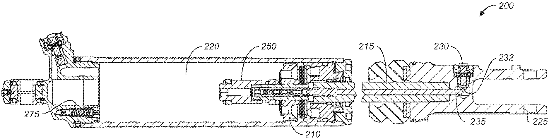
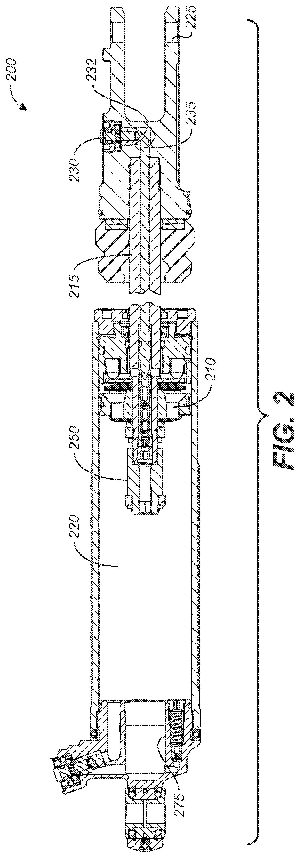
FIG. 2 is a section view showing a dampening assembly 200 of a shock absorber shown in an axially extended position. A dampening piston 210 is fixed relative to a shaft 215, both of which are axially movable relative to a housing or chamber 220. The piston 210 is equipped with fluid paths therethrough to permit dampening fluid within the chamber 220 to be metered through the piston 210. For example, when the shaft 215 moves into the chamber 220, fluid moves from a first side (the compression portion) to an opposite side (the rebound portion) of the chamber 220 through the paths formed in the piston 210. Additionally, fluid must move through a flow path from the chamber 220 into the external reservoir 125, thereby causing a reservoir floating piston to compress a gas chamber in the external reservoir 125. A configuration of a side reservoir, including a floating piston, is described in U.S. Pat. No. 7,374,028 which patent is entirely incorporated herein by reference.
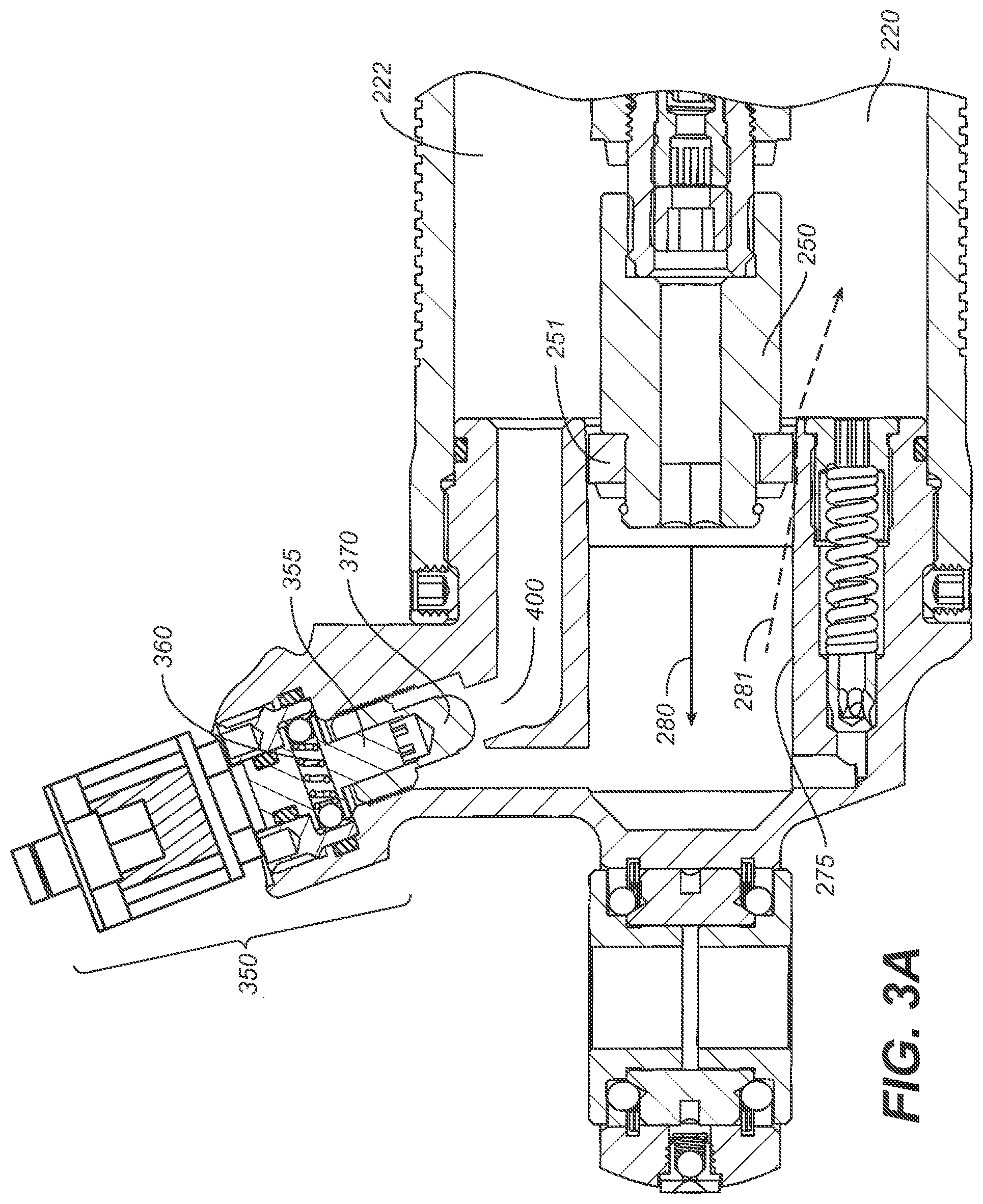
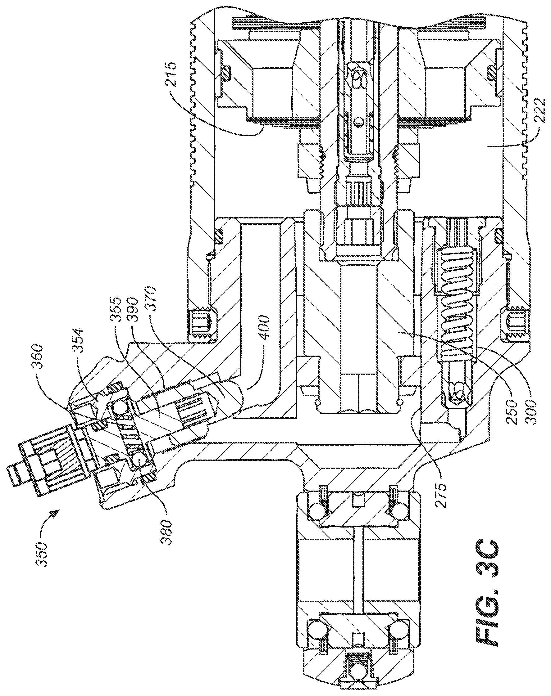
Also visible in FIG. 2 is a bottom out control feature. In one embodiment, the bottom out control feature utilizes a bottom out piston 250 connected at the end of the shaft 215 and spaced from the dampening piston 210. The bottom out piston is constructed and arranged to engage a bottom out cup 275 formed at the lower end of the chamber 220. As will be explained herein in more detail, the bottom out cup and bottom out piston operate with various dampening devices including a pressure relief or "blow-off" valve and an active valve to provide bottom out control.
However, various bottom out control features (both similar to the bottom out cup described herein, and using other bottom out control layouts, parts, systems, etc.) have been utilized in different shock set-ups such as those discussed in mountain bike forums, shock setup forums, and patents including U.S. Pat. No. 8,550,223 which is incorporated herein by reference in its entirety. However, the utilization of an active valve 350 to control any type of fluid flow pathways in a bottom out control feature has not been implemented prior to this disclosure. Moreover, the active valve 350, although described herein in a method of operation and design is not limited to the embodiment of a bottom out control feature using a bottom out cup, but could be easily added to any fluid flow pathway(s) that are a part of a bottom out control feature, system, or setup.
Example Active Bottom Out Valve
The active valve 350, in accordance with embodiments, includes a nipple 370, a body 355, and mating threads 390. In brief, body 355 is rotationally engaged with the nipple 370. A male hex member extends from an end of the body 355 into a female hex profile bore formed in the nipple 370. Such engagement transmits rotation from the body 355 to the nipple 370 while allowing axial displacement of the nipple 370 relative to the body 355. Therefore, while the body does not axially move upon rotation, the threaded nipple 370 interacts with mating threads 390 formed on an inside diameter of the bore to transmit axial motion, resulting from rotation and based on the pitch of the threads 390, of the nipple 370 towards and away from an orifice 400 and between a closed and fully open positions. Of note, depending on the movement of the body 355, the nipple 370 may occupy a position within respect to orifice 400 such that nipple 370 completely blocks orifice 400, partially blocks orifice 400, or does not block orifice 400 at all.
For example, active valve 350, when open, permits a first flow rate of the working fluid through orifice 400. In contrast, when active valve 350 is partially closed, a second flow rate of the working fluid though orifice 400 occurs. The second flow rate is less than the first flow rate but greater than no flow rate. When active valve 350 is completely closed, the flow rate of the working fluid though orifice 400 is statistically zero.
In one embodiment, instead of (or in addition to) restricting the flow through orifice 400, active valve 350 can vary a flow rate through an inlet or outlet passage within the active valve 350, itself. See, as an example, the electronic valve of FIGS. 2-4 of U.S. Pat. No. 9,353,818 which is incorporated by reference herein, in its entirety, as further example of different types of "electronic" or "active" valves). Thus, the active valve 350, can be used to meter the working fluid flow (e.g., control the rate of working fluid flow) with/or without adjusting the flow rate through orifice 400.
As can be seen in FIGS. 2-4D, due to the active valve 350 (or 450) arrangement, a relatively small solenoid (using relatively low amounts of power) can generate relatively large damping forces. Furthermore, due to incompressible fluid inside the dampening assembly 200, damping occurs as the distance between nipple 370 and orifice 400 is reduced. The result is a controllable damping rate. Certain active valve features are described and shown in U.S. Pat. Nos. 9,120,362; 8,627,932; 8,857,580; 9,033,122; and 9,239,090 which are incorporated herein, in their entirety, by reference.
It should be appreciated that when the body 355 rotates in a reverse direction than that described above and herein, the nipple 370 moves away from orifice 490 providing at least a partially opened fluid path.
FIG. 3A is a section view showing the bottom out piston 250 entering the bottom out cup 275 during a compression stroke of the shock absorber. The direction of movement of the piston 250 is illustrated by arrow 280. The bottom out piston includes a piston ring or piston seal 251 for axially slideable engagement with an inner diameter of the bottom out cup 275. In the embodiment of FIG. 3A, the upper end of the bottom out cup has a diameter that tapers outwards (i.e. larger) permitting, initially in the stroke, some fluid to pass through an annular area formed between the bottom out piston seal 251 and the inner diameter of the cup 275. The piston by-pass flow of fluid through the annular area and into a compression portion 222 of chamber 220 is illustrated by arrow 281.
FIG. 3B is a section view showing the bottom out cup 275 of FIG. 3A with the bottom out piston 250 fully engaged therein. As the piston completely engages the cup 275, dampening is increased because the shaft 215 can only progress further as fluid (e.g. substantially incompressible) is moved from the bottom out cup through one of two flow paths (e.g., flow path 301, and flow path 302) leading back into the compression portion 222 of chamber 220 (and ultimately also into external reservoir 125 if one is used).
FIG. 3B also shows various adjustable dampening mechanisms that work in conjunction with the bottom out cup and piston. At an end of flow path 301 is a pressure relief or "blow-off" valve 300, a high-speed compression circuit that operates at a blow-off threshold, typically due to a relatively rapid event like the rapid compression of the shock absorber. The blow-off valve 300 selectively allows fluid flow from the bottom out cup 275 to the compression portion 222 of chamber 220 at shaft speeds (in the direction of arrow 280) that create fluid pressures within the bottom out cup above the blow-off threshold pressure during engagement of piston 250 with bottom out cup 275. The blow-off valve generally comprises a valve opening, a blow-off valve 300 (or piston) and a compression spring 305. The blow-off pressure is determined by a combination of the spring rate of the spring 305, the preload on the spring 305 and the area of the blow-off valve 300 that is subject to fluid pressure from the bottom out cup 275. When fluid pressure in the cup rises above the predetermined (e.g. preset) threshold, the piston is forced away from the piston seat and allows fluid to flow through the valve opening and into the compression portion 222, thus lowering the pressure within the bottom out cup 275. The blow-off valve 300 is primarily a safety device and is typically set to crack or "blow-off", thereby allowing fluid flow into the compression portion of chamber 220, at a pressure that is relatively high but still low enough to prevent excess pressure build up in the bottom out cup 275 from damaging the shock or the vehicle in which the shock is integrated.
Visible in FIGS. 3A-D, at an end of fluid flow path 302 is an active valve 350. Active valve 350 is operable to provide an easily and readily adjustable dampening feature operable with the bottom out cup 275 and piston 250. In FIGS. 3A-B the active valve 350 is shown in an open position whereby fluid may flow through an orifice 400. In FIGS. 3C-D, the valve is shown in a closed position wherein orifice 400 is fully obstructed. The active valve 350 is disposed in a bore formed in the damper housing cap. The active valve 350 assembly consists of a solenoid 506 (of FIG. 5), body 355, nipple 379, and mating threads 390.
In one embodiment, the active valve 350 is a live valve. That is, one or more of components of active valve 350 (e.g., body 355, nipple 379, mating threads 390, or the like) will be actuated automatically based on actual terrain conditions. In operation of the active valve 350, a solenoid electronically turns body 355. As body 355 is turned, the indexing ring 360 consisting of two opposing, outwardly spring-biased balls 380 rotates among indentions formed on an inside diameter of a lock ring 354. The interaction between the balls and the indentions locks the body 355 at each rotational location until the balls 380 are urged out of the indentations by additional rotational force input provided to body 355. The result is that the body 355 will index at various points of its rotation so that positioning of the body 355, and the corresponding setting of active valve 350, is maintained against vibration of the shock and the vehicle while in use.
As the body 355 rotates, so does the valve or nipple 370 at an opposite end of the valve from the head. The body 355 is rotationally engaged with the nipple 370. A male hex member extends from an end of the body 355 into a female hex profile bore formed in the nipple 370. Such engagement transmits rotation from the body 355 to the nipple 370 while allowing axial displacement of the nipple 370 relative to the body 355. Therefore, while the body does not axially move upon rotation, the threaded nipple 370 interacts with mating threads 390 formed on an inside diameter of the bore to transmit axial motion, resulting from rotation and based on the pitch of the threads 390, of the nipple 370 towards and away from an orifice 400 and between a closed and fully open positions.
In one embodiment, the live operation includes an active signal received by a receiver at active valve 350 from a computing device. For example, the user would have an app on a smart phone (or other computing device) and would control the settings via the app. Thus, when the user wanted to adjust the flowrate of the fluid through orifice 400, they would provide the proper command from the computing device and it would be received at active valve 350 which would then automatically operate body 355 causing nipple 370, to close, open, partially close, or partially open orifice 400 to meter the fluid flow.
In operation, the blow-off valve 300 and active valve 350 operate independently of each other but each is designed to permit fluid to pass from the bottom out cup 275 to the compression portion 222 of the chamber 220 in order to lessen the increase in dampening effect (i.e. the "increase" being over that due to the piston 210 and the external reservoir 125 during the majority of the compression stroke) when the bottom out piston 250 engages the bottom out cup. Even when active valve 350 is completely closed with no fluid entering the compression portion of the chamber through the metering active valve 350 (i.e. the bottom out dampening rate is very high), the dampening rate will decrease to some extent when a threshold pressure of blow-off valve 300 is reached, thereby opening blow-off valve 300 and allowing fluid to flow from the bottom out cup 275 to the compression portion of the chamber 220 via flow path 302 and independently of orifice 400.
FIG. 3D is a similar view as shown in FIG. 3C showing a blow-off valve and an active valve having a second configuration in communication with the bottom out cup. FIG. 3D illustrates a section view similar to that of FIG. 3C. As such, and for purposes of clarity, only the differences between FIGS. 3C-3D will be discussed.
FIG. 3D shows an active valve that is operable to provide an easily and readily adjustable dampening feature operable with the bottom out cup 275 and piston 250 with another embodiment of an active valve 450 (as shown in detail in FIG. 7) which is a different configuration than active valve 350, but which operates in the same overall manner and with the same processes as described with respect to FIGS. 3A-C, except that the control of the fluid flow is performed through active valve 450 as it passes through orifice 400.
FIG. 4A is a section view showing the shaft 215 with another dampening mechanism operable in conjunction with the bottom out cup 275 and piston 250 and also to operate prior to engagement of the piston in the cup. As indicated by movement direction arrow 465 in FIG. 4A, the bottom out piston 250 is shown being removed from the bottom out cup 275. In the embodiment of FIG. 4A, the shaft 215 includes a fluid path formed in its interior and provides for fluid communication between the bottom out cup 275 and a rebound portion 221 of the chamber 220 during the rebound stroke. The path and direction of flow in the embodiment is illustrated by arrow 465. The path winds through a bore in the shaft that is formed coaxially with the centerline of the shaft. At one end, the fluid path including 475, terminates at a lower end of the bottom out piston 250 and at an upper end, the path terminates at an aperture(s) 460 intersecting the path designated by arrow 465 and leading into the chamber 220.
An adjustment mechanism described herein in relation to FIG. 2, and terminating in bullet shaped member (e.g. adjustable needle valve) 231 permits the volume of fluid flow, upon opening of the check valve 475, to be set by a user. As shown in FIG. 2, shaft 215 includes a mounting eye 225 (or clevis) at one end thereof. The mounting eye 225 includes a valve adjuster 230 which is user-adjustable and movable in and out (e.g. by threaded engagement) of the eye in a direction substantially perpendicular to the longitudinal axis of shaft 215. Shaft 215 also includes a coaxially mounted shaft 235 therein, where shaft 235 is axially movable relative to shaft 215. An end 232 of valve adjuster 230 contacts an end of shaft 235 and rotational movement of valve adjuster 230 causes axial movement of shaft 235 relative to shaft 215. Such axial movement of shaft 235 changes the position of a needle valve 231 inside the shaft and thereby adjusts the low speed fluid flow rate and maximum fluid flow rate though the piston shaft (in the direction that is not blocked by a check valve 475) and thereby allows manual adjustment of the dampening rate.
In addition to a fluid path, the shaft 215 of the embodiment is provided with an adjustable and reversible check valve 475 installed at an upper end of the path and permitting fluid to selectively move in one direction while preventing fluid from moving in an opposite direction. In the embodiment shown in FIG. 4A, fluid is only permitted to move toward the lower end of the bottom out piston 250 (as indicated by arrow 465) and is checked in the reverse direction. The check valve 475 is spring loaded to open at a predetermined (set) fluid pressure in the direction of permitted flow (the direction shown by arrow 465). Varying spring preload will vary the fluid pressure at which the check valve is set to crack.
In one embodiment, as shown, dampening of the shock absorber is reduced in the extending or rebound direction, because the fluid flow through the shaft permits a quicker extension or "rebound" of the shaft by permitting an additional volume of fluid to move from the rebound portion 221 of the chamber 220 to the region below the bottom out piston 250 (which, following bottom out, flows into the bottom out cup below piston 250), thus reducing force required to retract the bottom out piston 250 from the cup 275 and therefore, the shaft 215 and permitting a quicker extension. In another embodiment, not shown, the check valve 475 is reversed and dampening on the compression stroke is reduced by the allowance of additional fluid flow through the shaft 215 and along path designated by arrow 465 but in an opposite direction from the one shown in FIG. 4A as direction of arrow 465. Reversing the check valve from the shown embodiment results in the valve member 476 and seat 477 being oriented towards the bottom out piston.
In order to facilitate easy reversal and adjustment of the check valve, the bore of shaft 215 is provided with threads to accept a check valve cartridge 485. The check valve cartridge 485 is further secured within the shaft 215 by a threaded nut 486. The check valve cartridge 485 and the nut 486 are flush or below flush relative to the lower end of the shaft 215 and fit therein without additional shaft diameter or length, so that there is no interference with the interface between or operation or assembly of the piston 250 and the shaft 215. The shaft 215 having the provision for a modular check valve cartridge 485 allows for other interchangeable valve configurations without modifying surrounding hardware. For instance, the check valve cartridge 485 may be equipped with fluid flow resistors (chokes), filters or other micro-fluidic devices as, for example, are illustrated in The Lee Company Technical Hydraulic Handbook, which is copyright 1996 by The Lee Company and entirely incorporated by reference herein, or any suitable combination of the foregoing as may be desirable for the tailoring of flowing fluid characteristics. Further, the inclusion of such cartridge check valve requires no additional length in the overall shaft 215/piston 250 assembly.
In one embodiment the damping assembly 200 and bottom out feature are configured and operated, at the user's discretion, without the check valve 475 (or check valve cartridge 485) installed. In that embodiment fluid may flow along the path designated by arrow 465 in either direction, thereby reducing dampening characteristics in both the rebound and compression strokes to the extent allowed by adjustment of the needle valve 231. Alternatively, the needle valve may be completely closed into an adjacent end of check valve cartridge 485 thereby excluding fluid flow in both directions along the path designated by arrow 465.
In one embodiment (not shown) the bottom out chamber or "cup" is located proximate an end of the damping chamber corresponding to the hole through which the shaft enters that chamber. A "bottom out piston" surrounds the shaft and is axially movable relative thereto (there though). The primary damping piston includes a connector which connects it to the bottom out piston and the connector is capable of bearing tension between the two pistons but not compression. A simple embodiment of such a connector may comprise a flexible cable. The bottom out piston is forced into the bottom out cup by direct engagement of the "topping out" primary damping piston at near full extension of the shock absorber. In extended positions of the shock absorber the connector between the primary and bottom out pistons is slack. As the shock absorber is compressed to near bottom out position, the connector is placed in tension and begins to pull the bottom out piston from within the bottom out cup thereby creating a suction (or vacuum) within the bottom out cup. The bottom out cup includes a metering valve, in principle as described herein, for metering fluid through a path between (into) an interior of the bottom out cup (such interior formed by the cup and the engaged bottom out piston) and (from) the rebound chamber thereby relieving the vacuum while creating an increased damping effect near bottom out. It is contemplated that the "bottom out cup" and "bottom out piston" may include many varied embodiments while retaining adjustability.
Each dampening mechanism described is usable with a bottom out cup and piston to provide a variety of selectable and/or adjustable dampening options in a shock absorber near the end of a compression stroke (and some throughout either stroke) or beginning of a rebound stroke. Embodiments described herein may also be adapted to work with dampeners generally as if the bottom out piston 250 and the bottom out cup described herein where the dampening piston and cylinder. For example, active valve 350 can be initially set to permit a predetermined amount of fluid to flow between the cup and the compression portion 222 chamber 220 of the vehicle damping assembly 200. The blow-off valve 300, depending upon its setting, permits fluid flow in the event that pressure in the cup exceeds the threshold pressure of the blow-off valve circuit. Operation of the blow-off valve is in part determinable by the setting of active valve 350 as its more or less metering of fluid operates to lessen or increase, respectively, the fluid pressure in the bottom out cup. Also, the reversible check valve 475 in the hollow shaft can be arranged to reduce dampening in either the compression or the rebound stroke of the piston.
Referring still to FIGS. 3A-4D, in various embodiments of the present invention, damping assembly 200 includes a bottom out orifice 400 whose flow rate (or size of opening) is adjusted by the operation of nipple 370 of active valve 350, such that the flowrate of the fluid between the cup and the compression portion 222 of chamber 220 of the damper, via orifice 400 is automatically adjustable using active valve 350 to move nipple 370 closer to or further from orifice 400. In one such embodiment, active valve 350 is solenoid operated, hydraulically operated, pneumatically operated, or operated by any other suitable motive mechanism. Active valve 350 may be operated remotely by a switch or potentiometer located in the cockpit of a vehicle or attached to appropriate operational parts of a vehicle for timely activation (e.g. brake pedal) or may be operated in response to input from a microprocessor (e.g. calculating desired settings based on vehicle acceleration sensor data) or any suitable combination of activation means. In like manner, a controller for active valve 350 may be cockpit mounted and may be manually adjustable or microprocessor controlled or both or selectively either.
It may be desirable to increase the damping rate or effective stiffness of dampening assembly 200 when moving a vehicle from off-road to on highway use. Off-road use often requires a high degree of compliance to absorb shocks imparted by the widely varying terrain. On highway use, particularly with long wheel travel vehicles, often requires more rigid shock absorption to allow a user to maintain control of a vehicle at higher speeds. This may be especially true during cornering or braking.
One embodiment comprises a four-wheeled vehicle having dampening assembly 200 to automatically control the fluid flow between the cup and the compression portion 222 of chamber 220. As such, the damper is automatically adjustable using active valve 350 at each (of four) wheel.
For example, the opening size of orifice 400 which controls the flowrate of the fluid between the cup and the compression portion 222 of chamber 220 is automatically adjusted by active valve 350 (including, for example, a remotely controllable active valve). In one embodiment, each of the front shock absorbers may be electrically connected with a linear switch (such as that which operates an automotive brake light) that is activated in conjunction with the vehicle brake. When the brake is moved beyond a certain distance, corresponding usually to harder braking and hence potential for vehicle nose dive, the electric switch connects a power supply to a motive force generator for active valve 350 in the front shocks causes active valve 350 to automatically move body 355 and/or nipple 370 and cause nipple 370 to open, close, or partially close fluid flow through orifice 400.
In so doing, the reduction in fluid flow rate through orifice 400 increases the stiffness of that shock. As such, the front shocks become more rigid during hard braking. Other mechanisms may be used to trigger the shocks such as accelerometers (e.g. tri-axial) for sensing pitch and roll of the vehicle and activating, via a microprocessor, the appropriate amount of rotation of active valve 350 to cause nipple 370 to open, close, or partially close orifice 400 (and corresponding adjustment of the size of orifice 400 modifies the flowrate of the fluid between the cup and the compression portion 222 of chamber 220 for the corresponding dampening assembly 200) for optimum vehicle control.
In one embodiment, a vehicle steering column includes right turn and left turn limit switches such that a hard turn in either direction activates the appropriate adjustment of active valve 350 to cause nipple 370 to open, close, or partially close orifice 400 (and corresponding adjustment of the size of orifice 400 modifies the flowrate of the fluid between the cup and the compression portion 222 of chamber 220 for the corresponding dampening assembly 200) of shocks opposite that direction (for example, a hard, right turn would cause more rigid shocks on the vehicle's left side). Again, accelerometers in conjunction with a microprocessor (e.g., a comparer) and a switched power supply may perform the active valve 350 activation function by sensing the actual g-force associated with the turn (or braking; or acceleration for the rear shock activation) and triggering the appropriate amount of rotation of active valve 350 to cause nipple 370 to open, close, or partially close orifice 400 (and corresponding adjustment of the size of orifice 400 modifies the flowrate of the fluid between the cup and the compression portion 222 of chamber 220 for the corresponding dampening assembly 200) at a predetermined acceleration threshold value (e.g., a g-force).
FIGS. 4B-4D each illustrate a section view similar to that of FIG. 4A. As such, and for purposes of clarity, only the differences between each of FIGS. 4B-4D will be discussed. In FIGS. 4B-4D, active valve 350 is replaced with another configuration of an active valve (e.g., active valve 450 described in detail in FIG. 7). FIGS. 4B-4D also include an external reservoir 125 that is in fluid communication with the chamber 220 for receiving and supplying working fluid as the piston 210 moves in and out of the chamber 220. The external reservoir 125 includes a reservoir cylinder 416 in fluid communication with the compression portion 222 of chamber 220 via the fluid conduit 408. The external reservoir 125 also includes a floating piston 414 with a volume of gas on a backside 418 ("blind end" side) of it, the gas being compressible as the reservoir cylinder 416, on the "frontside" 412 fills with working fluid due to movement of the piston 210 into the chamber 220. Certain features of reservoir type dampers are shown and described in U.S. Pat. No. 7,374,028, which is incorporated herein, in its entirety, by reference.
FIG. 4B has an active valve 450 having a second configuration for controlling the bottom out (as described in detail in FIG. 7), external reservoir 125 and an (optional) non-active valve 479 for controlling the flow between the external reservoir 125 and the vehicle damping assembly 200 as indicated by flow arrows 444b, in accordance with an embodiment. In one embodiment, active valve 450 is a live valve as described in further detail in FIGS. 5-7 while non-active valve 479 refers to a manual valve that may be adjustable but is not electronically adjustable. In one embodiment, active valve 450 will be actuated automatically based on actual terrain conditions. For example, active valve 450 is operated as discussed in FIGS. 5-7 to open, close or partially allow flow through orifice 400 to modify the flowrate of the fluid between the cup and the compression portion 222 chamber 220 of the vehicle damping assembly 200.
In one embodiment, the live operation includes an active signal received by a receiver at active valve 450 from a computing system. Thus, to meter (or adjust) the flowrate of the fluid between the cup and the compression portion 222 chamber 220 of the vehicle damping assembly 200, via orifice 400, the command would be provided from the computing system and received at active valve 450 which would then automatically open, close or partially allow fluid flow through orifice 400.
FIG. 4C is a section view similar to FIG. 4A with a non-active valve 479 controlling the bottom out and active valve 450 having a second configuration for controlling flow to the external reservoir 125, in accordance with an embodiment. In other words, a non-active valve 479 is used in place of the active valve 450 in the bottom-out configuration and an active valve 450b is used to meter the fluid between the external reservoir 125 and the vehicle damping assembly 200 via fluid conduit 408. As discussed herein, active valve 450b can open or close the flow path (e.g., fluid conduit 408) between the external reservoir 125 and the vehicle damping assembly 200 as indicated by flow arrows 444b.
In one embodiment, active valve 450b is a live valve as described in further detail in FIGS. 5-7 while non-active valve 479 refers to a manual valve that may be adjustable but is not electronically adjustable. In one embodiment, active valve 450b will be actuated automatically based on actual terrain conditions. For example, active valve 450b is operated as discussed in FIGS. 5-7 to open, close or partially allow flow through fluid conduit 408 to modify the flowrate of the fluid between the external reservoir 125 and the vehicle damping assembly 200.
In one embodiment, the live operation includes an active signal received by a receiver at active valve 450b from a computing system. Thus, to meter (or adjust) the flowrate of the fluid between external reservoir 125 and the vehicle damping assembly 200, via fluid conduit 408, the command would be provided from the computing system and received at active valve 450b which would then automatically open, close or partially allow fluid flow through fluid conduit 408.
FIG. 4D is a section view similar to FIG. 4A with an active valve 450 having a second configuration for controlling the bottom out and second active valve 450b (which is similar to the active valve 350 and/or 450 as described herein, except that it is provided in fluid conduit 408 instead of orifice 400), in accordance with an embodiment. In FIG. 4D, external reservoir 125 is similar to external reservoir 125 of FIG. 4C in that active valve 450b is provided in the fluid conduit 408 which can open or close the flow path between the external reservoir 125 and the vehicle damping assembly 200 as indicated by flow arrows 444.
In one embodiment, both the active valve 450 and active valve 450b are live valves as described in further detail in FIGS. 5-7. In one embodiment, active valve 450 and/or active valve 450b will be actuated automatically based on actual terrain conditions. For example, active valve 450 and/or active valve 450b are operated as discussed in FIGS. 5-7 to open, close or partially allow flow through the different flow paths to modify the flowrate of the fluid through the different flow paths.
In one embodiment, the live operation includes an active signal received by a receiver at active valve 450 and/or active valve 450b from a computing system. Thus, to adjust the flowrate of the fluid between the cup and the compression portion 222 chamber 220 of the vehicle damping assembly 200, via orifice 400, the command would be provided from the computing system and received at active valve 450 which would then automatically open, close or partially allow fluid flow through orifice 400. Similarly, the computing system can provide an active signal received by a receiver at active valve 450b to adjust the flowrate of the fluid between the cup and the compression portion 222 chamber 220 of the vehicle damping assembly 200, via orifice 400, the would be provided from the computing system and received at active valve 450b which would then automatically open, close or partially allow fluid flow through orifice 400.
Although two active valves are shown in FIG. 4D, it is understood that any number of active valves corresponding to any number of fluid channels (e.g., bottom out channels, external reservoir channels, bottom out channels, etc.) for a corresponding number of vehicle suspension dampers could be used alone or in combination. That is, one or more active valves could be operated simultaneously or separately depending upon needs in a vehicular suspension system. For example, a suspension damper could have one, a combination of, or each of an active valve(s) and or inert valves: for an internal bottom out, for an external bottom out, for a fluid conduit 408 to the external reservoir 125, etc. In other words, anywhere there is a fluid flow path within a damping assembly 200, an active valve could be used. Moreover, the active valve could be alone or used in combination with other active valves, and/or other inert valves, at other fluid flow paths to automate one or more of the damping performance characteristics of the dampening assembly. Moreover, additional switches could permit individual operation of separate active valves.
FIG. 5 is a schematic diagram showing a control arrangement 500 for a remotely-operated active valve 350. As illustrated, a signal line 502 runs from a switch 504 to a solenoid 506. Thereafter, the solenoid 506 converts electrical energy into mechanical movement and rotates body 355 within active valve 350, In one embodiment, the rotation of body 355 causes indexing ring 360 consisting of two opposing, outwardly spring-biased balls 380 to rotate among indentions formed on an inside diameter of a lock ring 354.
As the body 355 rotates, nipple 370 at an opposite end of the valve is advanced or withdrawn from an opening in orifice 400. For example, the body 355 is rotationally engaged with the nipple 370. A male hex member extends from an end of the body 355 into a female hex profile bore formed in the nipple 370. Such engagement transmits rotation from the body 355 to the nipple 370 while allowing axial displacement of the nipple 370 relative to the body 355. Therefore, while the body does not axially move upon rotation, the threaded nipple 370 interacts with mating threads 390 formed on an inside diameter of the bore to transmit axial motion, resulting from rotation and based on the pitch of the threads 390, of the nipple 370 towards or away from an orifice 400, between a closed position, a partially open position, and a fully or completely open position.
Adjusting the opening of orifice 400 modifies the flowrate of the fluid between the cup and the compression portion 222 of chamber 220 thereby varying the stiffness of a corresponding dampening assembly 200. While FIG. 5 is simplified and involves control of a single active valve 350, it will be understood that any number of active valves corresponding to any number of fluid channels (e.g., bypass channels, external reservoir channels, bottom out channels, etc.) for a corresponding number of vehicle suspension dampers could be used alone or in combination. That is, one or more active valves could be operated simultaneously or separately depending upon needs in a vehicular suspension system. For example, a suspension damper could have one, a combination of, or each of an active valve(s): for a bottom out control, an internal bypass, for an external bypass, for a fluid conduit to the external reservoir 125, etc. In other words, anywhere there is a fluid flow path within a dampening assembly 200, an active valve could be used. Moreover, the active valve could be alone or used in combination with other active valves at other fluid flow paths to automate one or more of the damping performance characteristics of the dampening assembly. Moreover, additional switches could permit individual operation of separate active bottom out valves.
As discussed, a remotely-operable active valve 350 like the one described above is particularly useful with an on-/off-road vehicle. These vehicles can have more than 20'' of shock absorber travel to permit them to negotiate rough, uneven terrain at speed with usable shock absorbing function. In off-road applications, compliant dampening is necessary as the vehicle relies on its long travel suspension when encountering often large off-road obstacles. Operating a vehicle with very compliant, long travel suspension on a smooth road at road speeds can be problematic due to the springiness/sponginess of the suspension and corresponding vehicle handling problems associated with that (e.g. turning roll, braking pitch). Such compliance can cause reduced handling characteristics and even loss of control. Such control issues can be pronounced when cornering at high speed as a compliant, long travel vehicle may tend to roll excessively. Similarly, such a vehicle may include excessive pitch and yaw during braking and/or acceleration. With the remotely-operated active valve 350, the working size of orifice 400 is automatically adjusted thereby modifying the communication of fluid between the cup and the compression portion 222 of chamber 220 for the corresponding dampening assembly 200. Correspondingly, the dampening characteristics of dampening assembly 200 can be changed.
In addition to, or in lieu of, the simple, switch-operated remote arrangement of FIG. 5, the remotely-operable active valve 350 can be operated automatically based upon one or more driving conditions. FIG. 6 shows a schematic diagram of a control system 600 based upon any or all of vehicle speed, damper rod speed, and damper rod position. One embodiment of the arrangement of FIG. 6 is designed to automatically increase dampening in a shock absorber in the event a damper rod reaches a certain velocity in its travel towards the bottom end of a damper at a predetermined speed of the vehicle. In one embodiment, the control system 600 adds dampening (and control) in the event of rapid operation (e.g. high rod velocity) of the dampening assembly 200 to avoid a bottoming out of the damper rod as well as a loss of control that can accompany rapid compression of a shock absorber with a relative long amount of travel. In one embodiment, the control system 600 adds dampening (e.g., adjusts the size of the opening of orifice 400 by causing nipple 370 to open, close, or partially close orifice 400) in the event that the rod velocity in compression is relatively low but the rod progresses past a certain point in the travel.
Such configuration aids in stabilizing the vehicle against excessive low-rate suspension movement events such as cornering roll, braking and acceleration yaw and pitch and "g-out."
FIG. 6 illustrates, for example, a control system 600 including three variables: wheel speed, corresponding to the speed of a vehicle component (measured by wheel speed transducer 604), piston rod position (measured by piston rod position transducer 606), and piston rod velocity (measured by piston rod velocity transducer 608). Any or all of the variables shown may be considered by logic unit 602 in controlling the solenoids or other motive sources coupled to active valve 350 for changing the working size of the opening of orifice 400 by causing nipple 370 to open, close, or partially close orifice 400. Any other suitable vehicle operation variable may be used in addition to or in lieu of the variables discussed herein, such as, for example, piston rod compression strain, eyelet strain, vehicle mounted accelerometer (or tilt/inclinometer) data or any other suitable vehicle or component performance data.
In one embodiment, the piston's position within the damping chamber is determined using an accelerometer to sense modal resonance of the suspension damper. Such resonance will change depending on the position of the piston and an on-board processor (computer) is calibrated to correlate resonance with axial position. In one embodiment, a suitable proximity sensor or linear coil transducer or other electro-magnetic transducer is incorporated in the damping chamber to provide a sensor to monitor the position and/or speed of the piston (and suitable magnetic tag) with respect to a housing of the suspension damper.
In one embodiment, the magnetic transducer includes a waveguide and a magnet, such as a doughnut (toroidal) magnet that is joined to the cylinder and oriented such that the magnetic field generated by the magnet passes through the rod and the waveguide. Electric pulses are applied to the waveguide from a pulse generator that provides a stream of electric pulses, each of which is also provided to a signal processing circuit for timing purposes. When the electric pulse is applied to the waveguide, a magnetic field is formed surrounding the waveguide. Interaction of this field with the magnetic field from the magnet causes a torsional strain wave pulse to be launched in the waveguide in both directions away from the magnet. A coil assembly and sensing tape is joined to the waveguide. The strain wave causes a dynamic effect in the permeability of the sensing tape which is biased with a permanent magnetic field by the magnet. The dynamic effect in the magnetic field of the coil assembly due to the strain wave pulse, results in an output signal from the coil assembly that is provided to the signal processing circuit along signal lines.
By comparing the time of application of a particular electric pulse and a time of return of a sonic torsional strain wave pulse back along the waveguide, the signal processing circuit can calculate a distance of the magnet from the coil assembly or the relative velocity between the waveguide and the magnet. The signal processing circuit provides an output signal, which is digital or analog, proportional to the calculated distance and/or velocity. A transducer-operated arrangement for measuring piston rod speed and velocity is described in U.S. Pat. No. 5,952,823 and that patent is incorporated by reference herein in its entirety.
While transducers located at the suspension damper measure piston rod velocity (piston rod velocity transducer 608), and piston rod position (piston rod position transducer 606), a separate wheel speed transducer 604 for sensing the rotational speed of a wheel about an axle includes housing fixed to the axle and containing therein, for example, two permanent magnets. In one embodiment, the magnets are arranged such that an elongated pole piece commonly abuts first surfaces of each of the magnets, such surfaces being of like polarity. Two inductive coils having flux-conductive cores axially passing therethrough abut each of the magnets on second surfaces thereof, the second surfaces of the magnets again being of like polarity with respect to each other and of opposite polarity with respect to the first surfaces. Wheel speed transducers are described in U.S. Pat. No. 3,986,118 which is incorporated herein by reference in its entirety.
In one embodiment, as illustrated in FIG. 6, the logic unit 602 with user-definable settings receives inputs from piston rod position transducer 606, piston rod velocity transducer 608, as well as wheel speed transducer 604. Logic unit 602 is user-programmable and, depending on the needs of the operator, logic unit 602 records the variables and, then, if certain criteria are met, logic unit 602 sends its own signal to active valve 350 (e.g., the logic unit 602 is an activation signal provider) to cause active valve 350 to move into the desired state (e.g., adjust the flow rate by adjusting the distance between nipple 370 and orifice 400). Thereafter, the condition, state or position of active valve 350 is relayed back to logic unit 602 via an active valve monitor or the like.
In one embodiment, logic unit 602 shown in FIG. 6 assumes a single active valve 350 corresponding to a single orifice 400 of a single dampening assembly 200, but logic unit 602 is usable with any number of active valves or groups of active valves corresponding to any number of orifices, or groups of orifices. For instance, the suspension dampers on one side of the vehicle can be acted upon while the vehicles other suspension dampers remain unaffected.
While the examples illustrated relate to manual operation and automated operation based upon specific parameters, active valve 350 can be remotely-operated and can be used in a variety of ways with many different driving and road variables. In one example, active valve 350 is controlled based upon vehicle speed in conjunction with the angular location of the vehicle's steering wheel. In this manner, by sensing the steering wheel turn severity (angle of rotation), additional dampening (by adjusting the corresponding size of the opening of orifice 400 by causing nipple 370 to open, close, or partially close orifice 400) can be applied to one dampening assembly 200 or one set of vehicle suspension dampers on one side of the vehicle (suitable for example to mitigate cornering roll) in the event of a sharp turn at a relatively high speed.
In another example, a transducer, such as an accelerometer, measures other aspects of the vehicle's suspension system, like axle force and/or moments applied to various parts of the vehicle, like steering tie rods, and directs change to position of active valve 350 (and corresponding change to the working size of the opening of orifice 400 by causing nipple 370 to open, close, or partially close orifice 400) in response thereto. In another example, active valve 350 is controlled at least in part by a pressure transducer measuring pressure in a vehicle tire and adding dampening characteristics to some or all of the wheels (by adjusting the working size of the opening of orifice 400 by causing nipple 370 to open, close, or partially close orifice 400) in the event of, for example, an increased or decreased pressure reading. In one embodiment, active valve 350 is controlled in response to braking pressure (as measured, for example, by a brake pedal (or lever) sensor or brake fluid pressure sensor or accelerometer). In still another example, a parameter might include a gyroscopic mechanism that monitors vehicle trajectory and identifies a "spin-out" or other loss of control condition and adds and/or reduces dampening to some or all of the vehicle's dampers (by adjusting the working size of the opening of orifice 400 by causing nipple 370 to open, close, or partially close orifice 400 chambers) in the event of a loss of control to help the operator of the vehicle to regain control.
FIG. 7 is an enlarged view showing an embodiment of a remotely operable active valve 450. Although FIG. 7 shows the active valve 450 in a closed position (e.g. during a rebound stroke of the damper), the following discussion also includes the opening of active valve 450. Active valve 450 includes a valve body 704 housing a movable piston 705 which is sealed within the body. The piston 705 includes a sealed chamber 707 adjacent an annularly-shaped piston surface 706 at a first end thereof. The chamber 707 and annular piston surface 706 are in fluid communication with a port 725 accessed via opening 726. Two additional fluid communication points are provided in the body including an inlet 702 and an outlet 703 for fluid passing through the active valve 450.
Extending from a first end of the piston 705 is a shaft 710 having a cone-shaped valve member 712 (other shapes such as spherical or flat, with corresponding seats, will also work suitably well) disposed on an end thereof. The cone-shaped member 712 is telescopically mounted relative to, and movable on, the shaft 710 and is biased toward an extended position due to a spring 715 coaxially mounted on the shaft 710 between the member 712 and the piston 705. Due to the spring biasing, the cone-shaped member 712 normally seats itself against a seat 717 formed in an interior of the valve body 704.
As shown, the cone shaped member 712 is seated against seat 717 due to the force of the spring 715 and absent an opposite force from fluid entering the active valve 450 along orifice 400 (of FIGS. 3B-3D). As member 712 telescopes out, a gap 720 is formed between the end of the shaft 710 and an interior of member 712. A vent 721 is provided to relieve any pressure formed in the gap. With a fluid path through the active valve 450 (from 703 to 702) closed, fluid communication is substantially shut off from the rebound side of the cylinder into the valve body (and hence through the bottom out back to the compression side) and its "dead-end" path is shown by arrow 719.
In one embodiment, there is a manual pre-load adjustment on the spring 715 permitting a user to hand-load or un-load the spring using a threaded member 708 that transmits motion of the piston 705 towards and away from the conical member, thereby changing the compression on the spring 715.
Also shown in FIG. 7 is a plurality of valve operating cylinders 751, 752, 753. In one embodiment, the cylinders each include a predetermined volume of fluid 755 that is selectively movable in and out of each cylindrical body through the action of a separate corresponding piston 765 and rod 766 for each cylindrical body. A fluid path 770 runs between each cylinder and port 725 of the valve body where annular piston surface 706 is exposed to the fluid.
Because each cylinder has a specific volume of substantially incompressible fluid and because the volume of the sealed chamber 707 adjacent the annular piston surface 706 is known, the fluid contents of each cylinder can be used, individually, sequentially or simultaneously to move the piston a specific distance, thereby effecting the dampening characteristics of the system in a relatively predetermined and precise way.
While the cylinders 751-753 can be operated in any fashion, in the embodiment shown each piston 765 and rod 766 is individually operated by a solenoid 775 and each solenoid, in turn, is operable from a remote location of the vehicle, like a cab of a motor vehicle or even the handlebar area of a motor or bicycle (not shown). Electrical power to the solenoids 775 is available from an existing power source of a vehicle or is supplied from its own source, such as on-board batteries. Because the cylinders may be operated by battery or other electric power or even manually (e.g. by syringe type plunger), there is no requirement that a so-equipped suspension rely on any pressurized vehicle hydraulic system (e.g. steering, brakes) for operation. Further, because of the fixed volume interaction with the bottom out valve there is no issue involved in stepping from hydraulic system pressure to desired suspension bottom out operating pressure.
In one embodiment, e.g., when active valve 450 is in the damping-open position, fluid flow through orifice 400 provides adequate force on the member 712 to urge it backwards, at least partially loading the spring 715 and creating fluid path 701 from the orifice 400 into a rebound portion 134 of the vehicle damping assembly 200.
The characteristics of the spring 715 are typically chosen to permit active valve 450 (e.g. member 712) to open at a predetermined bottom out pressure, with a predetermined amount of control pressure applied to port 725, during a compression stroke of vehicle damping assembly 200. For a given spring 715, higher control pressure at port 725 will result in higher bottom out pressure required to open the active valve 450 and correspondingly higher damping resistance in orifice 400 (more compression damping due to the bottom out). In one embodiment, the control pressure at port 725 is raised high enough to effectively "lock" the bottom out closed resulting in a substantially rigid compression damper (particularly true when a solid damping piston is also used).
In one embodiment, the valve is open in both directions when the valve member 712 is "topped out" against valve body 704. In another embodiment however, when the valve piston 705 is abutted or "topped out" against valve body 704 the spring 715 and relative dimensions of the active valve 450 still allow for the cone member 712 to engage the valve seat 717 thereby closing the valve. In such embodiment backflow from the rebound side of the chamber 220 to the compression side is always substantially closed and cracking pressure from flow along orifice 400 is determined by the pre-compression in the spring 715. In such embodiment, additional fluid pressure may be added to the inlet through port 725 to increase the cracking pressure for flow along orifice 400 and thereby increase compression damping through the bottom out over that value provided by the spring compression "topped out." It is generally noteworthy that while the descriptions herein often relate to compression damping bottom out and rebound shut off, some or all of the bottom out channels (or channel) on a given suspension unit may be configured to allow rebound damping bottom out and shut off or impede compression damping bottom out.
FIG. 8 is a flowchart 800 of an example method of operational incorporation for an active bottom out valve operation in accordance with an embodiment. Although, a number of uses can and will be realized as active valve 450 is utilized to provide an active valve or semi-active valve bottom out zone, the following is one of a plurality of possible examples that could utilize the many additional capabilities that have heretofore remained unavailable to a manually adjustable bottom out zone.
In one embodiment, during tuning of a suspension and specifically each shock absorber 100 of the suspension, the ride zone portion of the shock absorber is setup to have low damping and the bottom out zone has a heavier damping (than the ride zone portion) to prevent bottom out on square edge hits when the electronics can't respond. However, large discrepancies in the damping settings between the ride zone and the BOC can cause the transition between the two damping settings to become noticeable and intrusive.
Without active valve 450 in the BOC (e.g., in a manual adjustable BOC), a compromise tune is utilized between the damping characteristics of the main piston and the damping characteristics of the BOC to reduce the feel during the damping transition between the ride zone and the BOC.
In one embodiment, by utilizing at least one active valve 450 in shock absorber 100, the tuning of the damping characteristics of the ride zone portion and/or the bottom out zone of the shock absorber 100 can be tuned with significantly less compromise than the manually adjustable setup.
For example, when there is an active valve 450 that provides adjustable damping to the BOC, the bottom out zone damping can electronically vary based on terrain and/or rider behavior. For example, more damping when the system/rider/mapping prioritizes bottoming resistance and less damping when the system/rider/mapping prioritizes quality feel. Moreover, because of the location of the active valve 450 in the BOC there is minimal hysteresis effect and the adjustments of the active valve 450 could occur very quickly.
In another embodiment, when there is plurality of active valve 450, e.g., an active valve that provides adjustable damping to the damping portion and one that provides adjustable damping to the BOC, the ride zone damping and the bottom out zone damping can be jointly and/or independently varied based on terrain, rider behavior, speed, feel, etc. That is, more ride zone and/or bottom out zone damping when the system/rider/mapping prioritizes bottoming resistance and less ride zone and/or bottom out zone damping when the system/rider/mapping prioritizes quality feel.
At 810, the initial suspension tune setting is established. E.g., in one embodiment, the initial tune sets the ride zone portion of the shock absorber range of operation has low damping and the BO zone portion of the shock absorber range of operation to have heavier damping (than the ride zone portion) to prevent bottom out on square edge hits.
At 820, the active valve 450 BOC (or damping or both bottom out and damping) setting(s) is checked (as described in detail in FIGS. 5-7) for its present damping characteristic settings and is adjusted as needed.
At 830, the bottoming resistance is prioritized and the damping of active valve 450 is adjusted to provide more damping.
At 840, the quality feel is prioritized and the damping of active valve 450 is adjusted to provide less damping.
Although a single flowchart is shown, it should be appreciated that the flowchart 800 could be similarly utilized by each of a plurality of active valves within the single shock absorber; by every of a plurality of active valves within the single shock absorber; by an active valve in each of a plurality of shock absorbers within a vehicle suspension; by a plurality of active valves in a plurality of shock absorbers within a vehicle suspension; by every active valve in a plurality of shock absorbers within a vehicle suspension; and by every active valve in every shock absorber within a vehicle suspension.
The foregoing Description of Embodiments is not intended to be exhaustive or to limit the embodiments to the precise form described. Instead, example embodiments in this Description of Embodiments have been presented in order to enable persons of skill in the art to make and use embodiments of the described subject matter. Moreover, various embodiments have been described in various combinations. However, any two or more embodiments could be combined. Although some embodiments have been described in a language specific to structural features and/or methodological acts, it is to be understood that the subject matter defined in the appended claims is not necessarily limited to the specific features or acts described above. Rather, the specific features and acts described above are disclosed by way of illustration and as example forms of implementing the claims and their equivalents.
* * * * *
References
D00000
D00001
D00002
D00003
D00004
D00005
D00006
D00007
D00008
D00009
D00010
D00011
D00012

XML
uspto.report is an independent third-party trademark research tool that is not affiliated, endorsed, or sponsored by the United States Patent and Trademark Office (USPTO) or any other governmental organization. The information provided by uspto.report is based on publicly available data at the time of writing and is intended for informational purposes only.
While we strive to provide accurate and up-to-date information, we do not guarantee the accuracy, completeness, reliability, or suitability of the information displayed on this site. The use of this site is at your own risk. Any reliance you place on such information is therefore strictly at your own risk.
All official trademark data, including owner information, should be verified by visiting the official USPTO website at www.uspto.gov. This site is not intended to replace professional legal advice and should not be used as a substitute for consulting with a legal professional who is knowledgeable about trademark law.