Multi-level inverter
Yoscovich , et al. April 5, 2
U.S. patent number 11,296,590 [Application Number 17/108,678] was granted by the patent office on 2022-04-05 for multi-level inverter. This patent grant is currently assigned to Solaredge Technologies Ltd.. The grantee listed for this patent is Solaredge Technologies Ltd.. Invention is credited to Yoav Galin, Tzachi Glovinsky, Guy Sella, Ilan Yoscovich.


View All Diagrams
| United States Patent | 11,296,590 |
| Yoscovich , et al. | April 5, 2022 |
Multi-level inverter
Abstract
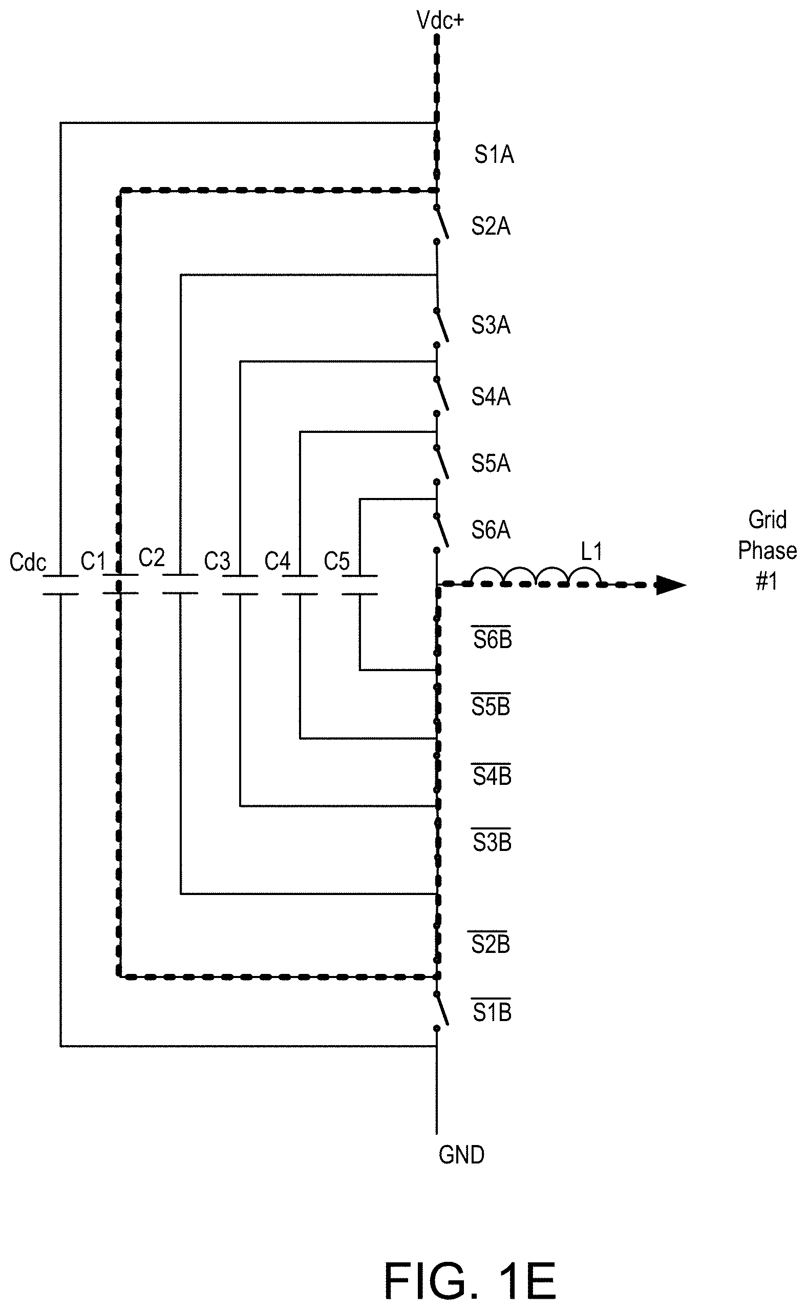
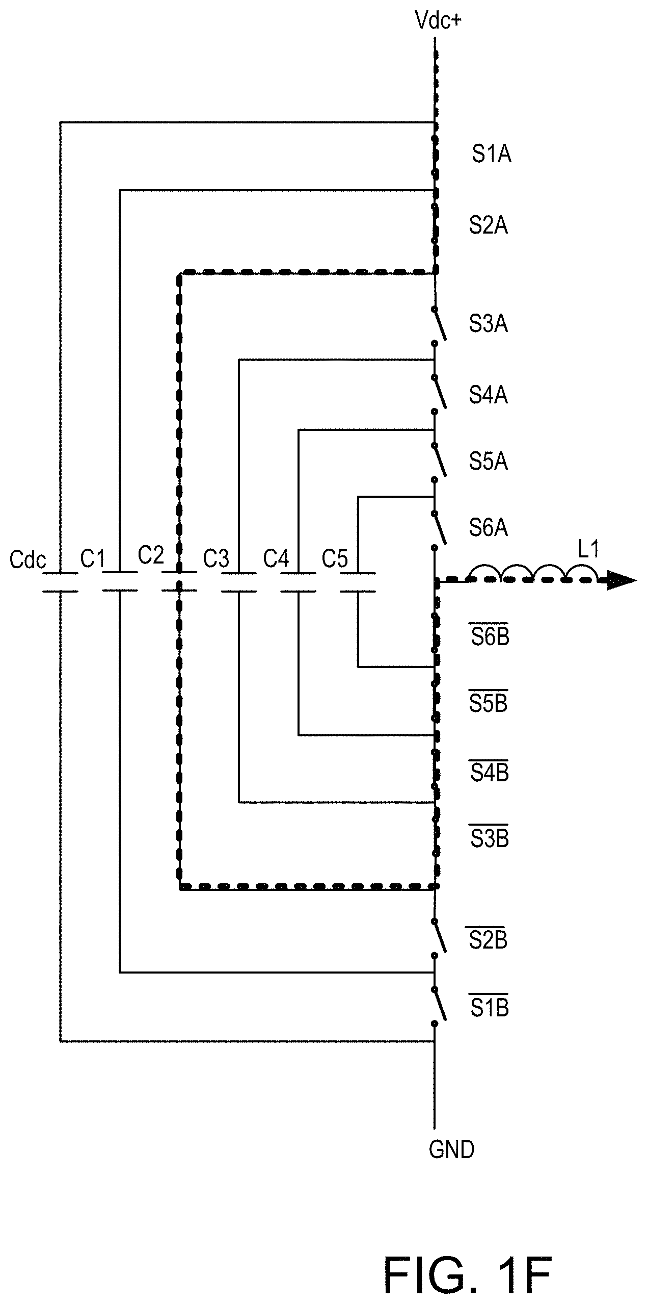
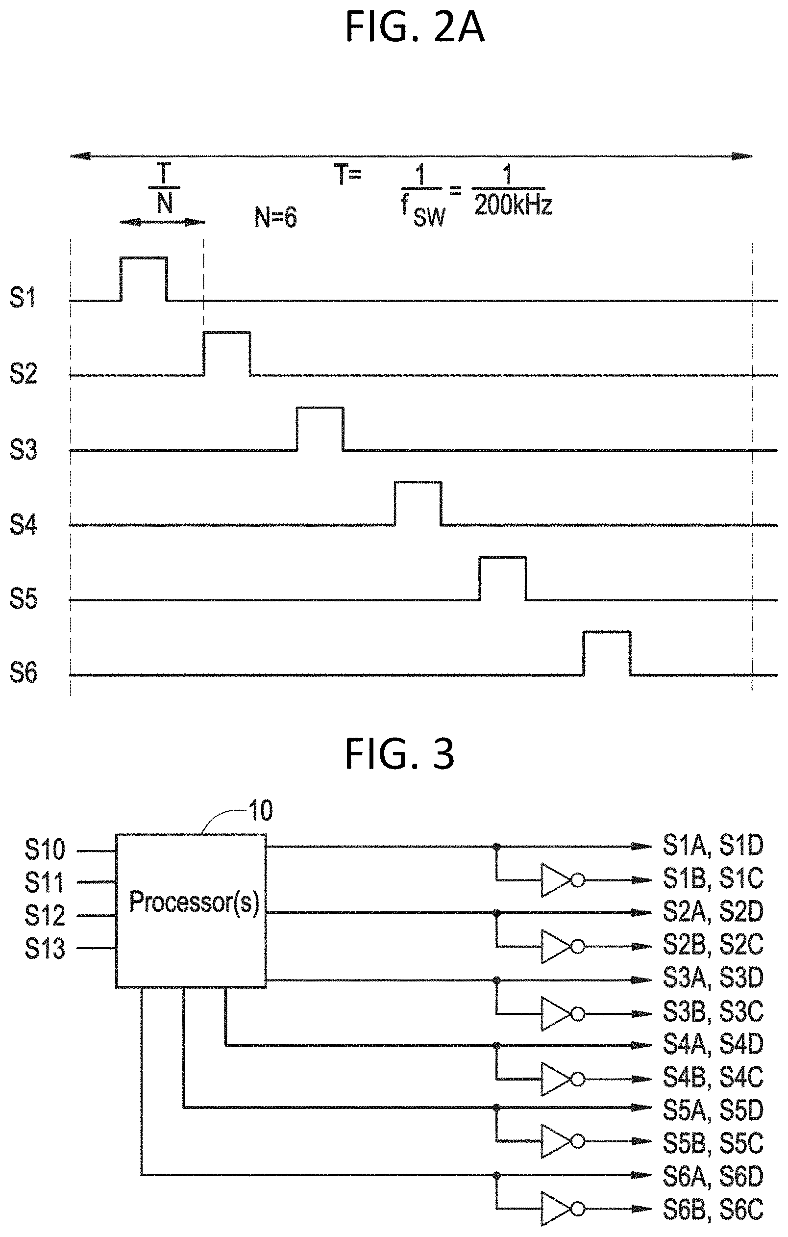
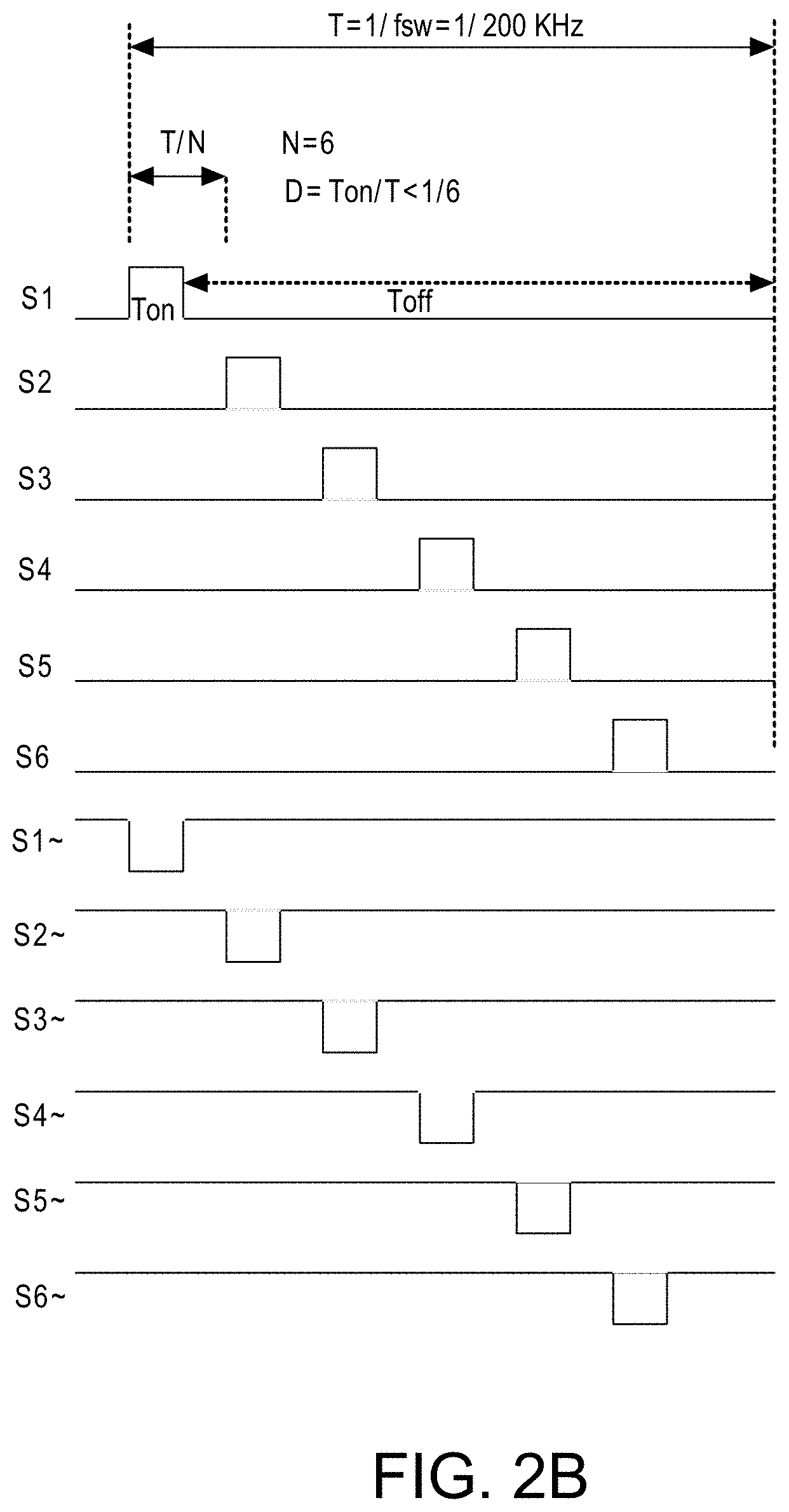
A multi-level inverter having one or more banks, each bank containing a plurality of low voltage MOSFET transistors. A processor configured to switch the plurality of low voltage MOSFET transistors in each bank to switch at multiple times during each cycle.
| Inventors: | Yoscovich; Ilan (Ramat Gan, IL), Glovinsky; Tzachi (Petah Tikva, IL), Sella; Guy (Bitan Aharon, IL), Galin; Yoav (Raanana, IL) | ||||||||||
|---|---|---|---|---|---|---|---|---|---|---|---|
| Applicant: |
|
||||||||||
| Assignee: | Solaredge Technologies Ltd.
(Herzeliya, IL) |
||||||||||
| Family ID: | 1000006216877 | ||||||||||
| Appl. No.: | 17/108,678 | ||||||||||
| Filed: | December 1, 2020 |
Prior Publication Data
| Document Identifier | Publication Date | |
|---|---|---|
| US 20210083564 A1 | Mar 18, 2021 | |
Related U.S. Patent Documents
| Application Number | Filing Date | Patent Number | Issue Date | ||
|---|---|---|---|---|---|
| 16870025 | May 8, 2020 | 10886832 | |||
| 16442214 | Jun 30, 2020 | 10700588 | |||
| 15054647 | Sep 3, 2019 | 10404154 | |||
| 14485682 | Apr 19, 2016 | 9318974 | |||
| 61970788 | Mar 26, 2014 | ||||
| Current U.S. Class: | 1/1 |
| Current CPC Class: | H02M 7/537 (20130101); H02M 7/483 (20130101); H02M 1/08 (20130101); H02M 1/126 (20130101); H02M 1/143 (20130101); H02M 7/4835 (20210501); H02M 1/0054 (20210501) |
| Current International Class: | H02M 7/483 (20070101); H02M 1/12 (20060101); H02M 7/537 (20060101); H02M 1/08 (20060101); H02M 1/14 (20060101); H02M 1/00 (20060101) |
References Cited [Referenced By]
U.S. Patent Documents
| 2367925 | January 1945 | Brown |
| 2758219 | August 1956 | Miller |
| 2852721 | September 1958 | Harders et al. |
| 3369210 | February 1968 | Manickella |
| 3392326 | July 1968 | Lamberton |
| 3496029 | February 1970 | King et al. |
| 3566143 | February 1971 | Paine et al. |
| 3581212 | May 1971 | McMurray |
| 3596229 | July 1971 | Hohorst |
| 3657657 | April 1972 | Jefferson |
| 3696286 | October 1972 | Ule |
| 3867643 | February 1975 | Baker et al. |
| 3958136 | May 1976 | Schroeder |
| 4060757 | November 1977 | McMurray |
| 4101816 | July 1978 | Shepter |
| 4104687 | August 1978 | Zulaski |
| 4129788 | December 1978 | Chavannes |
| 4146785 | March 1979 | Neale |
| 4161771 | July 1979 | Bates |
| 4170735 | October 1979 | Codina et al. |
| 4171861 | October 1979 | Hohorst |
| 4183079 | January 1980 | Wachi |
| 4257087 | March 1981 | Cuk |
| 4270163 | May 1981 | Baker |
| 4296461 | October 1981 | Mallory et al. |
| 4321581 | March 1982 | Tappeiner et al. |
| 4327318 | April 1982 | Kwon et al. |
| 4336613 | June 1982 | Hewes |
| 4346341 | August 1982 | Blackburn et al. |
| 4356542 | October 1982 | Bruckner et al. |
| 4363040 | December 1982 | Inose |
| 4367557 | January 1983 | Stern et al. |
| 4375662 | March 1983 | Baker |
| 4382382 | May 1983 | Wang |
| 4384321 | May 1983 | Rippel |
| 4394607 | July 1983 | Lemirande |
| 4404472 | September 1983 | Steigerwald |
| 4405977 | September 1983 | Bhagwat et al. |
| 4412142 | October 1983 | Ragonese et al. |
| 4452867 | June 1984 | Conforti |
| 4453207 | June 1984 | Paul |
| 4458204 | July 1984 | Weber |
| 4460232 | July 1984 | Sotolongo |
| 4470213 | September 1984 | Thompson |
| 4479175 | October 1984 | Gille et al. |
| 4481654 | November 1984 | Daniels et al. |
| 4488136 | December 1984 | Hansen et al. |
| 4526553 | July 1985 | Guerrero |
| 4545997 | October 1985 | Wong et al. |
| 4549254 | October 1985 | Kissel |
| 4554502 | November 1985 | Rohatyn |
| 4554515 | November 1985 | Burson et al. |
| 4564895 | January 1986 | Glennon |
| 4574250 | March 1986 | Senderowicz |
| 4580090 | April 1986 | Bailey et al. |
| 4591965 | May 1986 | Dickerson |
| 4598330 | July 1986 | Woodworth |
| 4602322 | July 1986 | Merrick |
| 4604567 | August 1986 | Chetty |
| 4608686 | August 1986 | Barsellotti |
| 4623753 | November 1986 | Feldman et al. |
| 4626983 | December 1986 | Harada et al. |
| 4631565 | December 1986 | Tihanyi |
| 4637677 | January 1987 | Barkus |
| 4639844 | January 1987 | Gallios et al. |
| 4641042 | February 1987 | Miyazawa |
| 4641079 | February 1987 | Kato et al. |
| 4644458 | February 1987 | Harafuji et al. |
| 4649334 | March 1987 | Nakajima |
| 4652770 | March 1987 | Kumano |
| 4670828 | June 1987 | Shekhawat et al. |
| 4683529 | July 1987 | Bucher, II |
| 4685040 | August 1987 | Steigerwald et al. |
| 4686617 | August 1987 | Colton |
| 4706181 | November 1987 | Mercer |
| 4719553 | January 1988 | Hinckley |
| 4720667 | January 1988 | Lee et al. |
| 4720668 | January 1988 | Lee et al. |
| 4736151 | April 1988 | Dishner |
| 4772994 | September 1988 | Harada et al. |
| 4783728 | November 1988 | Hoffman |
| 4816736 | March 1989 | Dougherty et al. |
| 4819121 | April 1989 | Saito et al. |
| RE33057 | September 1989 | Clegg et al. |
| 4864213 | September 1989 | Kido |
| 4868379 | September 1989 | West |
| 4873480 | October 1989 | Lafferty |
| 4888063 | December 1989 | Powell |
| 4888702 | December 1989 | Gerken et al. |
| 4899269 | February 1990 | Rouzies |
| 4903851 | February 1990 | Slough |
| 4906859 | March 1990 | Kobayashi et al. |
| 4910518 | March 1990 | Kim et al. |
| 4928056 | May 1990 | Pease |
| 4947100 | August 1990 | Dhyanchand et al. |
| 4951117 | August 1990 | Kasai |
| 4978870 | December 1990 | Chen et al. |
| 4987360 | January 1991 | Thompson |
| 5001415 | March 1991 | Watkinson |
| 5013990 | May 1991 | Weber |
| 5027051 | June 1991 | Lafferty |
| 5027059 | June 1991 | de Montgolfier et al. |
| 5045988 | September 1991 | Gritter et al. |
| 5081558 | January 1992 | Mahler |
| 5093583 | March 1992 | Mashino et al. |
| 5138422 | August 1992 | Fujii et al. |
| 5143556 | September 1992 | Matlin |
| 5144222 | September 1992 | Herbert |
| 5155670 | October 1992 | Brian |
| 5159255 | October 1992 | Weber |
| 5172309 | December 1992 | DeDoncker et al. |
| 5191519 | March 1993 | Kawakami |
| 5196781 | March 1993 | Jamieson et al. |
| 5233509 | August 1993 | Ghotbi |
| 5235266 | August 1993 | Schaffrin |
| 5237194 | August 1993 | Takahashi |
| 5268832 | December 1993 | Kandatsu |
| 5280133 | January 1994 | Nath |
| 5280232 | January 1994 | Kohl et al. |
| 5287261 | February 1994 | Ehsani |
| 5289361 | February 1994 | Vinciarelli |
| 5289998 | March 1994 | Bingley et al. |
| 5327071 | July 1994 | Frederick et al. |
| 5329222 | July 1994 | Gyugyi et al. |
| 5345375 | September 1994 | Mohan |
| 5361196 | November 1994 | Tanamachi et al. |
| 5373433 | December 1994 | Thomas |
| 5379209 | January 1995 | Goff |
| 5381327 | January 1995 | Fan |
| 5402060 | March 1995 | Erisman |
| 5404059 | April 1995 | Loffler |
| 5408171 | April 1995 | Eitzmann et al. |
| 5412558 | May 1995 | Sakurai et al. |
| 5413313 | May 1995 | Mutterlein et al. |
| 5442358 | August 1995 | Keeler et al. |
| 5446645 | August 1995 | Shirahama et al. |
| 5460546 | October 1995 | Kunishi et al. |
| 5472614 | December 1995 | Rossi |
| 5475818 | December 1995 | Molyneaux et al. |
| 5479337 | December 1995 | Voigt |
| 5493154 | February 1996 | Smith et al. |
| 5497289 | March 1996 | Sugishima et al. |
| 5504415 | April 1996 | Podrazhansky et al. |
| 5504418 | April 1996 | Ashley |
| 5504449 | April 1996 | Prentice |
| 5508658 | April 1996 | Nishioka |
| 5513075 | April 1996 | Capper et al. |
| 5517378 | May 1996 | Asplund et al. |
| 5530335 | June 1996 | Decker et al. |
| 5539238 | July 1996 | Malhi |
| 5548504 | August 1996 | Takehara |
| 5563780 | October 1996 | Goad |
| 5565855 | October 1996 | Knibbe |
| 5566022 | October 1996 | Segev |
| 5576941 | November 1996 | Nguyen et al. |
| 5580395 | December 1996 | Yoshioka et al. |
| 5585749 | December 1996 | Pace et al. |
| 5598326 | January 1997 | Liu et al. |
| 5604430 | February 1997 | Decker et al. |
| 5616913 | April 1997 | Litterst |
| 5625539 | April 1997 | Nakata et al. |
| 5625545 | April 1997 | Hammond |
| 5626619 | May 1997 | Jacobson et al. |
| 5631534 | May 1997 | Lewis |
| 5635864 | June 1997 | Jones |
| 5636107 | June 1997 | Lu et al. |
| 5638263 | June 1997 | Opal et al. |
| 5642275 | June 1997 | Peng et al. |
| 5644212 | July 1997 | Takahashi |
| 5644219 | July 1997 | Kurokawa |
| 5644483 | July 1997 | Peng et al. |
| 5646501 | July 1997 | Fishman et al. |
| 5648731 | July 1997 | Decker et al. |
| 5659465 | August 1997 | Flack et al. |
| 5677833 | October 1997 | Bingley |
| 5684385 | November 1997 | Guyonneau et al. |
| 5686766 | November 1997 | Tamechika |
| 5703390 | December 1997 | Itoh |
| 5708576 | January 1998 | Jones et al. |
| 5719758 | February 1998 | Nakata et al. |
| 5722057 | February 1998 | Wu |
| 5726615 | March 1998 | Bloom |
| 5731603 | March 1998 | Nakagawa et al. |
| 5734565 | March 1998 | Mueller et al. |
| 5747967 | May 1998 | Muljadi et al. |
| 5751120 | May 1998 | Zeitler et al. |
| 5751138 | May 1998 | Venkata et al. |
| 5773963 | June 1998 | Blanc et al. |
| 5777515 | July 1998 | Kimura |
| 5777858 | July 1998 | Rodulfo |
| 5780092 | July 1998 | Agbo et al. |
| 5790396 | August 1998 | Miyazaki et al. |
| 5793184 | August 1998 | O'Connor |
| 5798631 | August 1998 | Spee et al. |
| 5801519 | September 1998 | Midya et al. |
| 5804894 | September 1998 | Leeson et al. |
| 5812045 | September 1998 | Ishikawa et al. |
| 5814970 | September 1998 | Schmidt |
| 5821734 | October 1998 | Faulk |
| 5822186 | October 1998 | Bull et al. |
| 5838148 | November 1998 | Kurokami et al. |
| 5844439 | December 1998 | Zortea |
| 5847549 | December 1998 | Dodson, III |
| 5859772 | January 1999 | Hilpert |
| 5869956 | February 1999 | Nagao et al. |
| 5873738 | February 1999 | Shimada et al. |
| 5886882 | March 1999 | Rodulfo |
| 5886890 | March 1999 | Ishida et al. |
| 5892354 | April 1999 | Nagao et al. |
| 5892677 | April 1999 | Chang |
| 5898585 | April 1999 | Sirichote et al. |
| 5903138 | May 1999 | Hwang et al. |
| 5905645 | May 1999 | Cross |
| 5910892 | June 1999 | Lyons et al. |
| 5917722 | June 1999 | Singh |
| 5919314 | July 1999 | Kim |
| 5923100 | July 1999 | Lukens et al. |
| 5923158 | July 1999 | Kurokami et al. |
| 5929614 | July 1999 | Copple |
| 5930128 | July 1999 | Dent |
| 5930131 | July 1999 | Feng |
| 5932994 | August 1999 | Jo et al. |
| 5933327 | August 1999 | Leighton et al. |
| 5933339 | August 1999 | Duba et al. |
| 5936856 | August 1999 | Xiang |
| 5943229 | August 1999 | Sudhoff |
| 5945806 | August 1999 | Faulk |
| 5946206 | August 1999 | Shimizu et al. |
| 5949668 | September 1999 | Schweighofer |
| 5955885 | September 1999 | Kurokami et al. |
| 5961739 | October 1999 | Osborne |
| 5963010 | October 1999 | Hayashi et al. |
| 5963078 | October 1999 | Wallace |
| 5973368 | October 1999 | Pearce et al. |
| 5982646 | November 1999 | Lyons et al. |
| 5990659 | November 1999 | Frannhagen |
| 6002290 | December 1999 | Avery et al. |
| 6005788 | December 1999 | Lipo et al. |
| 6021052 | February 2000 | Unger et al. |
| 6026286 | February 2000 | Long |
| 6031399 | February 2000 | Vu et al. |
| 6031736 | February 2000 | Takehara et al. |
| 6031738 | February 2000 | Lipo et al. |
| 6037720 | March 2000 | Wong et al. |
| 6038148 | March 2000 | Farrington et al. |
| 6046470 | April 2000 | Williams et al. |
| 6046919 | April 2000 | Madenokouji et al. |
| 6050779 | April 2000 | Nagao et al. |
| 6058031 | May 2000 | Lyons et al. |
| 6058035 | May 2000 | Madenokouji et al. |
| 6060859 | May 2000 | Jonokuchi |
| 6064086 | May 2000 | Nakagawa et al. |
| 6075350 | June 2000 | Peng |
| 6078511 | June 2000 | Fasullo et al. |
| 6081104 | June 2000 | Kem |
| 6082122 | July 2000 | Madenokouji et al. |
| 6083164 | July 2000 | Oppelt et al. |
| 6087738 | July 2000 | Hammond |
| 6093885 | July 2000 | Takehara et al. |
| 6094129 | July 2000 | Baiatu |
| 6101073 | August 2000 | Takehara |
| 6105317 | August 2000 | Tomiuchi et al. |
| 6111188 | August 2000 | Kurokami et al. |
| 6111391 | August 2000 | Cullen |
| 6111767 | August 2000 | Handleman |
| 6130458 | October 2000 | Takagi et al. |
| 6150739 | November 2000 | Baumgartl et al. |
| 6151234 | November 2000 | Oldenkamp |
| 6160722 | December 2000 | Thommes et al. |
| 6163086 | December 2000 | Choo |
| 6166455 | December 2000 | Li |
| 6166527 | December 2000 | Dwelley et al. |
| 6169678 | January 2001 | Kondo et al. |
| 6175219 | January 2001 | Imamura et al. |
| 6175512 | January 2001 | Hagihara et al. |
| 6191456 | February 2001 | Stoisiek et al. |
| 6205012 | March 2001 | Lear |
| 6205042 | March 2001 | Bixel |
| RE37126 | April 2001 | Peng et al. |
| 6219623 | April 2001 | Wills |
| 6225793 | May 2001 | Dickmann |
| 6236580 | May 2001 | Mello et al. |
| 6255360 | July 2001 | Domschke et al. |
| 6255804 | July 2001 | Herniter et al. |
| 6256234 | July 2001 | Keeth et al. |
| 6259234 | July 2001 | Perol |
| 6262555 | July 2001 | Hammond et al. |
| 6262558 | July 2001 | Weinberg |
| 6269010 | July 2001 | Ma et al. |
| 6275016 | August 2001 | Ivanov |
| 6281485 | August 2001 | Siri |
| 6285572 | September 2001 | Onizuka et al. |
| 6292379 | September 2001 | Edevold et al. |
| 6301128 | October 2001 | Jang et al. |
| 6301130 | October 2001 | Aiello et al. |
| 6304065 | October 2001 | Wittenbreder |
| 6307749 | October 2001 | Daanen et al. |
| 6311137 | October 2001 | Kurokami et al. |
| 6316716 | November 2001 | Hilgrath |
| 6320769 | November 2001 | Kurokami et al. |
| 6331670 | December 2001 | Takehara et al. |
| 6339538 | January 2002 | Handleman |
| 6340851 | January 2002 | Rinaldi et al. |
| 6346451 | February 2002 | Simpson et al. |
| 6350944 | February 2002 | Sherif et al. |
| 6351130 | February 2002 | Preiser et al. |
| 6366483 | April 2002 | Ma et al. |
| 6369461 | April 2002 | Jungreis et al. |
| 6369462 | April 2002 | Siri |
| 6380719 | April 2002 | Underwood et al. |
| 6396170 | May 2002 | Lautenberg et al. |
| 6396239 | May 2002 | Benn et al. |
| 6404655 | June 2002 | Welches |
| 6417644 | July 2002 | Hammond et al. |
| 6422145 | July 2002 | Gavrilovic et al. |
| 6424207 | July 2002 | Johnson |
| 6425248 | July 2002 | Tonomura et al. |
| 6429546 | August 2002 | Ropp et al. |
| 6429621 | August 2002 | Arai |
| 6433522 | August 2002 | Siri |
| 6433978 | August 2002 | Neiger et al. |
| 6441597 | August 2002 | Lethellier |
| 6445599 | September 2002 | Nguyen |
| 6448489 | September 2002 | Kimura et al. |
| 6452814 | September 2002 | Wittenbreder |
| 6459596 | October 2002 | Corzine |
| 6465910 | October 2002 | Young et al. |
| 6469919 | October 2002 | Bennett |
| 6472254 | October 2002 | Cantarini et al. |
| 6480403 | November 2002 | Bijlenga |
| 6483203 | November 2002 | McCormack |
| 6493246 | December 2002 | Suzui et al. |
| 6501362 | December 2002 | Hoffman et al. |
| 6503649 | January 2003 | Czajkowski et al. |
| 6507176 | January 2003 | Wittenbreder, Jr. |
| 6509712 | January 2003 | Landis |
| 6515215 | February 2003 | Mimura |
| 6519165 | February 2003 | Koike |
| 6519169 | February 2003 | Asplund et al. |
| 6528977 | March 2003 | Arakawa |
| 6531848 | March 2003 | Chitsazan et al. |
| 6545211 | April 2003 | Mimura |
| 6548205 | April 2003 | Leung et al. |
| 6556330 | April 2003 | Holcombe |
| 6556461 | April 2003 | Khersonsky et al. |
| 6556661 | April 2003 | Ingalsbe et al. |
| 6560131 | May 2003 | vonBrethorst |
| 6577087 | June 2003 | Su |
| 6587051 | July 2003 | Takehara et al. |
| 6590793 | July 2003 | Nagao et al. |
| 6590794 | July 2003 | Carter |
| 6593520 | July 2003 | Kondo et al. |
| 6593521 | July 2003 | Kobayashi |
| 6603672 | August 2003 | Deng et al. |
| 6608468 | August 2003 | Nagase |
| 6611130 | August 2003 | Chang |
| 6611441 | August 2003 | Kurokami et al. |
| 6621719 | September 2003 | Steimer et al. |
| 6628011 | September 2003 | Droppo et al. |
| 6633824 | October 2003 | Dollar, II |
| 6650031 | November 2003 | Goldack |
| 6650371 | November 2003 | Morrish et al. |
| 6650560 | November 2003 | MacDonald et al. |
| 6653549 | November 2003 | Matsushita et al. |
| 6657419 | December 2003 | Renyolds |
| 6664762 | December 2003 | Kutkut |
| 6672018 | January 2004 | Shingleton |
| 6678174 | January 2004 | Suzui et al. |
| 6690590 | February 2004 | Stamenic et al. |
| 6690796 | February 2004 | Farris et al. |
| 6693327 | February 2004 | Priefert et al. |
| 6693781 | February 2004 | Kroker |
| 6697271 | February 2004 | Corzine |
| 6700351 | March 2004 | Blair et al. |
| 6709291 | March 2004 | Wallace et al. |
| 6724593 | April 2004 | Smith |
| 6731136 | May 2004 | Knee |
| 6738692 | May 2004 | Schienbein et al. |
| 6744643 | June 2004 | Luo et al. |
| 6757185 | June 2004 | Rojas Romero |
| 6765315 | July 2004 | Hammerstrom et al. |
| 6768047 | July 2004 | Chang et al. |
| 6768180 | July 2004 | Salama et al. |
| 6788033 | September 2004 | Vinciarelli |
| 6788146 | September 2004 | Forejt et al. |
| 6795318 | September 2004 | Haas et al. |
| 6800964 | October 2004 | Beck |
| 6801442 | October 2004 | Suzui et al. |
| 6807069 | October 2004 | Nieminen et al. |
| 6809942 | October 2004 | Madenokouji et al. |
| 6810339 | October 2004 | Wills |
| 6812396 | November 2004 | Makita et al. |
| 6837739 | January 2005 | Gorringe et al. |
| 6838611 | January 2005 | Kondo et al. |
| 6838856 | January 2005 | Raichle |
| 6842354 | January 2005 | Tallam et al. |
| 6844739 | January 2005 | Kasai et al. |
| 6850074 | February 2005 | Adams et al. |
| 6850424 | February 2005 | Baudelot et al. |
| 6856102 | February 2005 | Lin et al. |
| 6882131 | April 2005 | Takada et al. |
| 6888728 | May 2005 | Takagi et al. |
| 6894911 | May 2005 | Telefus et al. |
| 6897370 | May 2005 | Kondo et al. |
| 6897784 | May 2005 | Goehlich |
| 6914418 | July 2005 | Sung |
| 6919714 | July 2005 | Delepaut |
| 6927955 | August 2005 | Suzui et al. |
| 6930899 | August 2005 | Bakran et al. |
| 6933627 | August 2005 | Wilhelm |
| 6933714 | August 2005 | Fasshauer et al. |
| 6936995 | August 2005 | Kapsokavathis et al. |
| 6940735 | September 2005 | Deng et al. |
| 6949843 | September 2005 | Dubovsky |
| 6950323 | September 2005 | Achleitner et al. |
| 6954366 | October 2005 | Lai et al. |
| 6963147 | November 2005 | Kurokami et al. |
| 6966184 | November 2005 | Toyomura et al. |
| 6969967 | November 2005 | Su |
| 6980655 | December 2005 | Farris et al. |
| 6980783 | December 2005 | Liu et al. |
| 6984967 | January 2006 | Notman |
| 6984970 | January 2006 | Capel |
| 6987444 | January 2006 | Bub et al. |
| 6996741 | February 2006 | Pittelkow et al. |
| 7030597 | April 2006 | Bruno et al. |
| 7031176 | April 2006 | Kotsopoulos et al. |
| 7038430 | May 2006 | Itabashi et al. |
| 7042195 | May 2006 | Tsunetsugu et al. |
| 7045991 | May 2006 | Nakamura et al. |
| 7046531 | May 2006 | Zocchi et al. |
| 7050311 | May 2006 | Lai et al. |
| 7053506 | May 2006 | Alonso et al. |
| 7061211 | June 2006 | Satoh et al. |
| 7061214 | June 2006 | Mayega et al. |
| 7064967 | June 2006 | Ichinose et al. |
| 7068017 | June 2006 | Willner et al. |
| 7072194 | July 2006 | Nayar et al. |
| 7078883 | July 2006 | Chapman et al. |
| 7079406 | July 2006 | Kurokami et al. |
| 7087332 | August 2006 | Harris |
| 7090509 | August 2006 | Gilliland et al. |
| 7091707 | August 2006 | Cutler |
| 7097516 | August 2006 | Werner et al. |
| 7099169 | August 2006 | West et al. |
| 7119629 | October 2006 | Nielsen et al. |
| 7126053 | October 2006 | Kurokami et al. |
| 7126294 | October 2006 | Minami et al. |
| 7138786 | November 2006 | Ishigaki et al. |
| 7142997 | November 2006 | Widner |
| 7148669 | December 2006 | Maksimovic et al. |
| 7150938 | December 2006 | Munshi et al. |
| 7158359 | January 2007 | Bertele et al. |
| 7158395 | January 2007 | Deng et al. |
| 7161082 | January 2007 | Matsushita et al. |
| 7174973 | February 2007 | Lysaght |
| 7183667 | February 2007 | Colby et al. |
| 7190143 | March 2007 | Wei et al. |
| 7193826 | March 2007 | Crane et al. |
| 7193872 | March 2007 | Siri |
| 7202653 | April 2007 | Pai |
| 7208674 | April 2007 | Aylaian |
| 7218541 | May 2007 | Price et al. |
| 7219673 | May 2007 | Lemak |
| 7230837 | June 2007 | Huang et al. |
| 7231773 | June 2007 | Crane et al. |
| 7248946 | July 2007 | Bashaw et al. |
| 7256566 | August 2007 | Bhavaraju et al. |
| 7259474 | August 2007 | Blanc |
| 7262979 | August 2007 | Wai et al. |
| 7276886 | October 2007 | Kinder et al. |
| 7277304 | October 2007 | Stancu et al. |
| 7281141 | October 2007 | Elkayam et al. |
| 7282814 | October 2007 | Jacobs |
| 7291036 | November 2007 | Daily et al. |
| RE39976 | January 2008 | Schiff et al. |
| 7315052 | January 2008 | Alter |
| 7319313 | January 2008 | Dickerson et al. |
| 7319763 | January 2008 | Bank et al. |
| 7324361 | January 2008 | Siri |
| 7336004 | February 2008 | Lai |
| 7336056 | February 2008 | Dening |
| 7339287 | March 2008 | Jepsen et al. |
| 7348802 | March 2008 | Kasanyal et al. |
| 7352154 | April 2008 | Cook |
| 7361952 | April 2008 | Miura et al. |
| 7371963 | May 2008 | Suenaga et al. |
| 7372709 | May 2008 | Mazumder et al. |
| 7372712 | May 2008 | Stancu et al. |
| 7375994 | May 2008 | Andreycak |
| 7385300 | June 2008 | Huff et al. |
| 7385380 | June 2008 | Ishigaki et al. |
| 7385833 | June 2008 | Keung |
| 7388348 | June 2008 | Mattichak |
| 7394237 | July 2008 | Chou et al. |
| 7398012 | July 2008 | Koellner |
| 7405117 | July 2008 | Zuniga et al. |
| 7412056 | August 2008 | Farris et al. |
| 7414870 | August 2008 | Rottger et al. |
| 7420354 | September 2008 | Cutler |
| 7420815 | September 2008 | Love |
| 7432691 | October 2008 | Cutler |
| 7435134 | October 2008 | Lenox |
| 7435897 | October 2008 | Russell |
| 7443052 | October 2008 | Wendt et al. |
| 7443152 | October 2008 | Utsunomiya |
| 7445178 | November 2008 | McCoskey et al. |
| 7450401 | November 2008 | Iida |
| 7456510 | November 2008 | Ito et al. |
| 7456523 | November 2008 | Kobayashi |
| 7463500 | December 2008 | West |
| 7466566 | December 2008 | Fukumoto |
| 7471014 | December 2008 | Lum et al. |
| 7471524 | December 2008 | Batarseh et al. |
| 7471532 | December 2008 | Salama et al. |
| 7479774 | January 2009 | Wai et al. |
| 7482238 | January 2009 | Sung |
| 7492898 | February 2009 | Farris et al. |
| 7495419 | February 2009 | Ju |
| 7495938 | February 2009 | Wu et al. |
| 7499291 | March 2009 | Han |
| 7504811 | March 2009 | Watanabe et al. |
| 7518346 | April 2009 | Prexl et al. |
| 7538451 | May 2009 | Nomoto |
| 7558087 | July 2009 | Meysenc et al. |
| 7560915 | July 2009 | Ito et al. |
| 7573732 | August 2009 | Teichmann et al. |
| 7589437 | September 2009 | Henne et al. |
| 7595616 | September 2009 | Prexl et al. |
| 7598714 | October 2009 | Stanley |
| 7599200 | October 2009 | Tomonaga |
| 7600349 | October 2009 | Liebendorfer |
| 7602080 | October 2009 | Hadar et al. |
| 7605498 | October 2009 | Ledenev et al. |
| 7612283 | November 2009 | Toyomura et al. |
| 7623663 | November 2009 | Farris et al. |
| 7626834 | December 2009 | Chisenga et al. |
| 7633284 | December 2009 | Ingram et al. |
| 7646116 | January 2010 | Batarseh et al. |
| 7649434 | January 2010 | Xu et al. |
| 7663268 | February 2010 | Wen et al. |
| 7667342 | February 2010 | Matsumoto et al. |
| 7679941 | March 2010 | Raju et al. |
| 7701083 | April 2010 | Savage |
| 7709727 | May 2010 | Roehrig et al. |
| 7710082 | May 2010 | Escobar Valderrama et al. |
| 7719140 | May 2010 | Ledenev et al. |
| 7719864 | May 2010 | Kemahan et al. |
| 7723865 | May 2010 | Kitanaka |
| 7733069 | June 2010 | Toyomura et al. |
| 7733178 | June 2010 | Delano et al. |
| 7748175 | July 2010 | Liebendorfer |
| 7759575 | July 2010 | Jones et al. |
| 7763807 | July 2010 | Richter |
| 7768350 | August 2010 | Srinivasan et al. |
| 7780472 | August 2010 | Lenox |
| 7782031 | August 2010 | Qiu et al. |
| 7783389 | August 2010 | Yamada et al. |
| 7787270 | August 2010 | NadimpalliRaju et al. |
| 7787273 | August 2010 | Lu et al. |
| 7796409 | September 2010 | Knott |
| 7800348 | September 2010 | Zargari |
| 7804282 | September 2010 | Bertele |
| 7807919 | October 2010 | Powell et al. |
| 7808125 | October 2010 | Sachdeva et al. |
| 7812701 | October 2010 | Lee et al. |
| 7821225 | October 2010 | Chou et al. |
| 7830681 | November 2010 | Abolhassani et al. |
| 7834579 | November 2010 | Nojima |
| 7839022 | November 2010 | Wolfs |
| 7839023 | November 2010 | Jacobson et al. |
| 7843085 | November 2010 | Ledenev et al. |
| 7864497 | January 2011 | Quardt et al. |
| 7868599 | January 2011 | Rahman et al. |
| 7872528 | January 2011 | Bockelman et al. |
| 7880334 | February 2011 | Evans et al. |
| 7883808 | February 2011 | Norimatsu et al. |
| 7884278 | February 2011 | Powell et al. |
| 7890080 | February 2011 | Wu et al. |
| 7893022 | February 2011 | Zhang et al. |
| 7893346 | February 2011 | Nachamkin et al. |
| 7898112 | March 2011 | Powell et al. |
| 7900361 | March 2011 | Adest et al. |
| 7906870 | March 2011 | Ohm |
| 7919952 | April 2011 | Fahrenbruch |
| 7919953 | April 2011 | Porter et al. |
| 7920393 | April 2011 | Bendre et al. |
| 7925552 | April 2011 | Tarbell et al. |
| 7932693 | April 2011 | Lee et al. |
| 7940537 | May 2011 | Abolhassan et al. |
| 7944191 | May 2011 | Xu |
| 7945413 | May 2011 | Krein |
| 7948217 | May 2011 | Oohara et al. |
| 7948221 | May 2011 | Watanabe et al. |
| 7952897 | May 2011 | Nocentini et al. |
| 7960650 | June 2011 | Richter et al. |
| 7960950 | June 2011 | Glovinsky |
| 7961817 | June 2011 | Dong et al. |
| 7969126 | June 2011 | Stanley |
| 7969133 | June 2011 | Zhang et al. |
| 7986535 | July 2011 | Jacobson et al. |
| 8003885 | August 2011 | Richter et al. |
| 8004113 | August 2011 | Sander et al. |
| 8004116 | August 2011 | Ledenev et al. |
| 8004117 | August 2011 | Adest et al. |
| 8004866 | August 2011 | Bucella et al. |
| 8013472 | September 2011 | Adest et al. |
| 8018331 | September 2011 | Jang |
| 8018748 | September 2011 | Leonard |
| 8026639 | September 2011 | Sachdeva et al. |
| 8026763 | September 2011 | Dawson et al. |
| 8031495 | October 2011 | Sachdeva et al. |
| 8039730 | October 2011 | Hadar et al. |
| 8045346 | October 2011 | Abolhassan et al. |
| 8058747 | November 2011 | Avrutsky et al. |
| 8058752 | November 2011 | Erickson, Jr. et al. |
| 8067855 | November 2011 | Mumtaz et al. |
| 8077437 | December 2011 | Mumtaz et al. |
| 8089780 | January 2012 | Mochikawa et al. |
| 8089785 | January 2012 | Rodriguez |
| 8090548 | January 2012 | Abdennadher et al. |
| 8093756 | January 2012 | Porter et al. |
| 8093757 | January 2012 | Wolfs |
| 8098055 | January 2012 | Avrutsky et al. |
| 8102074 | January 2012 | Hadar et al. |
| 8102144 | January 2012 | Capp et al. |
| 8111052 | February 2012 | Glovinsky |
| 8116103 | February 2012 | Zacharias et al. |
| 8130501 | March 2012 | Ledezma et al. |
| 8138631 | March 2012 | Allen et al. |
| 8138914 | March 2012 | Wong et al. |
| 8144490 | March 2012 | El-Barbari et al. |
| 8144491 | March 2012 | Bendre et al. |
| 8158877 | April 2012 | Klein et al. |
| 8169108 | May 2012 | Dupuis et al. |
| 8174138 | May 2012 | Castelli Dezza et al. |
| 8179147 | May 2012 | Dargatz et al. |
| 8184460 | May 2012 | O'Brien et al. |
| 8194856 | June 2012 | Farris et al. |
| 8204709 | June 2012 | Presher, Jr. et al. |
| 8212408 | July 2012 | Fishman |
| 8212409 | July 2012 | Bettenwort et al. |
| 8223515 | July 2012 | Abolhassani et al. |
| 8230257 | July 2012 | Wilson |
| 8232948 | July 2012 | Yin et al. |
| 8233625 | July 2012 | Farris et al. |
| 8271599 | September 2012 | Eizips et al. |
| 8274172 | September 2012 | Hadar et al. |
| 8279640 | October 2012 | Abolhassani et al. |
| 8279644 | October 2012 | Zhang et al. |
| 8284021 | October 2012 | Farris et al. |
| 8289742 | October 2012 | Adest et al. |
| 8294306 | October 2012 | Kumar et al. |
| 8304932 | November 2012 | Ledenev et al. |
| 8310101 | November 2012 | Amaratunga et al. |
| 8314375 | November 2012 | Arditi et al. |
| 8314602 | November 2012 | Hosini et al. |
| 8319471 | November 2012 | Adest et al. |
| 8325059 | December 2012 | Rozenboim |
| 8344548 | January 2013 | Stern |
| 8344551 | January 2013 | Nielsen |
| 8369113 | February 2013 | Rodriguez |
| 8374009 | February 2013 | Feng et al. |
| 8385091 | February 2013 | Nielsen |
| 8391031 | March 2013 | Garrity |
| 8391032 | March 2013 | Garrity et al. |
| 8400796 | March 2013 | Dofnas et al. |
| 8405248 | March 2013 | Mumtaz et al. |
| 8405349 | March 2013 | Kikinis et al. |
| 8405367 | March 2013 | Chisenga et al. |
| 8410889 | April 2013 | Garrity et al. |
| 8411474 | April 2013 | Roesner et al. |
| 8415552 | April 2013 | Hadar et al. |
| 8415937 | April 2013 | Hester |
| 8427010 | April 2013 | Bose et al. |
| 8436592 | May 2013 | Saitoh |
| 8441820 | May 2013 | Shen et al. |
| 8461809 | June 2013 | Rodriguez |
| 8471514 | June 2013 | Zargari et al. |
| 8471604 | June 2013 | Permuy et al. |
| 8472220 | June 2013 | Garrity et al. |
| 8472221 | June 2013 | Lee |
| 8473250 | June 2013 | Adest et al. |
| 8476689 | July 2013 | Chang |
| 8482156 | July 2013 | Spanoche et al. |
| 8492710 | July 2013 | Fuhrer et al. |
| 8493754 | July 2013 | Wambsganss et al. |
| 8498137 | July 2013 | Joseph |
| 8509032 | August 2013 | Rakib |
| 8526205 | September 2013 | Garrity |
| 8531055 | September 2013 | Adest et al. |
| 8542512 | September 2013 | Garrity |
| 8547717 | October 2013 | Kshirsagar |
| 8558405 | October 2013 | Brogan et al. |
| 8559193 | October 2013 | Mazumder |
| 8570005 | October 2013 | Lubomirsky |
| 8570017 | October 2013 | Perichon et al. |
| 8570776 | October 2013 | Kolar et al. |
| 8581441 | November 2013 | Rotzoll et al. |
| 8587141 | November 2013 | Bjerknes et al. |
| 8599588 | December 2013 | Adest et al. |
| 8619446 | December 2013 | Liu et al. |
| 8624443 | January 2014 | Mumtaz |
| 8642879 | February 2014 | Gilmore et al. |
| 8653689 | February 2014 | Rozenboim |
| 8664796 | March 2014 | Nielsen |
| 8669675 | March 2014 | Capp et al. |
| 8670255 | March 2014 | Gong et al. |
| 8674548 | March 2014 | Mumtaz |
| 8674668 | March 2014 | Chisenga et al. |
| 8686333 | April 2014 | Arditi et al. |
| 8751053 | June 2014 | Hadar et al. |
| 8773236 | July 2014 | Makhota et al. |
| 8811047 | August 2014 | Rodriguez |
| 8823212 | September 2014 | Garrity et al. |
| 8823218 | September 2014 | Hadar et al. |
| 8841916 | September 2014 | Avrutsky |
| 8853886 | October 2014 | Avrutsky et al. |
| 8854019 | October 2014 | Levesque et al. |
| 8854193 | October 2014 | Makhota et al. |
| 8860241 | October 2014 | Hadar et al. |
| 8860246 | October 2014 | Hadar et al. |
| 8867248 | October 2014 | Wang et al. |
| 8917156 | December 2014 | Garrity et al. |
| 8922061 | December 2014 | Arditi |
| 8933321 | January 2015 | Hadar et al. |
| 8934269 | January 2015 | Garrity |
| 8937822 | January 2015 | Dent |
| 9735703 | August 2017 | Dent |
| 10128774 | November 2018 | Dent |
| 10135361 | November 2018 | Dent |
| 10666161 | May 2020 | Dent |
| 10784710 | September 2020 | Dent |
| 2001/0023703 | September 2001 | Kondo et al. |
| 2001/0032664 | October 2001 | Takehara et al. |
| 2001/0034982 | November 2001 | Nagao et al. |
| 2001/0035180 | November 2001 | Kimura et al. |
| 2001/0048605 | December 2001 | Kurokami et al. |
| 2001/0050102 | December 2001 | Matsumi et al. |
| 2001/0054881 | December 2001 | Watanabe |
| 2002/0002040 | January 2002 | Kline et al. |
| 2002/0014262 | February 2002 | Matsushita et al. |
| 2002/0034083 | March 2002 | Ayyanar et al. |
| 2002/0038667 | April 2002 | Kondo et al. |
| 2002/0041505 | April 2002 | Suzui et al. |
| 2002/0044473 | April 2002 | Toyomura et al. |
| 2002/0047309 | April 2002 | Droppo et al. |
| 2002/0056089 | May 2002 | Houston |
| 2002/0063552 | May 2002 | Arakawa |
| 2002/0078991 | June 2002 | Nagao et al. |
| 2002/0080027 | June 2002 | Conley |
| 2002/0085397 | July 2002 | Suzui et al. |
| 2002/0113689 | August 2002 | Gehlot et al. |
| 2002/0118559 | August 2002 | Kurokami et al. |
| 2002/0149950 | October 2002 | Takebayashi |
| 2002/0162585 | November 2002 | Sugawara et al. |
| 2002/0165458 | November 2002 | Carter et al. |
| 2002/0177401 | November 2002 | Judd et al. |
| 2002/0179140 | December 2002 | Toyomura |
| 2002/0180408 | December 2002 | McDaniel et al. |
| 2003/0002303 | January 2003 | Riggio et al. |
| 2003/0038615 | February 2003 | Elbanhawy |
| 2003/0043611 | March 2003 | Bockle et al. |
| 2003/0047207 | March 2003 | Aylaian |
| 2003/0058593 | March 2003 | Bertele et al. |
| 2003/0058662 | March 2003 | Baudelot et al. |
| 2003/0066076 | April 2003 | Minahan |
| 2003/0066555 | April 2003 | Hui et al. |
| 2003/0075211 | April 2003 | Makita et al. |
| 2003/0080741 | May 2003 | LeRow et al. |
| 2003/0085621 | May 2003 | Potega |
| 2003/0090233 | May 2003 | Browe |
| 2003/0094931 | May 2003 | Renyolds |
| 2003/0156439 | August 2003 | Ohmichi et al. |
| 2003/0164695 | September 2003 | Fasshauer et al. |
| 2003/0185026 | October 2003 | Matsuda et al. |
| 2003/0193821 | October 2003 | Krieger et al. |
| 2003/0201674 | October 2003 | Droppo et al. |
| 2003/0212440 | November 2003 | Boveja |
| 2003/0214274 | November 2003 | Lethellier |
| 2003/0223257 | December 2003 | Onoe |
| 2004/0004402 | January 2004 | Kippley |
| 2004/0022081 | February 2004 | Erickson et al. |
| 2004/0024937 | February 2004 | Duncan et al. |
| 2004/0041548 | March 2004 | Perry |
| 2004/0056768 | March 2004 | Matsushita et al. |
| 2004/0061527 | April 2004 | Knee |
| 2004/0076028 | April 2004 | Achleitner et al. |
| 2004/0117676 | June 2004 | Kobayashi et al. |
| 2004/0118446 | June 2004 | Toyomura |
| 2004/0123894 | July 2004 | Erban |
| 2004/0124816 | July 2004 | DeLepaut |
| 2004/0125618 | July 2004 | De Rooij et al. |
| 2004/0140719 | July 2004 | Vulih et al. |
| 2004/0144043 | July 2004 | Stevenson et al. |
| 2004/0164718 | August 2004 | McDaniel et al. |
| 2004/0165408 | August 2004 | West et al. |
| 2004/0167676 | August 2004 | Mizumaki |
| 2004/0169499 | September 2004 | Huang et al. |
| 2004/0170038 | September 2004 | Ichinose et al. |
| 2004/0189432 | September 2004 | Yan et al. |
| 2004/0201279 | October 2004 | Templeton |
| 2004/0201933 | October 2004 | Blanc |
| 2004/0207366 | October 2004 | Sung |
| 2004/0211458 | October 2004 | Gui et al. |
| 2004/0223351 | November 2004 | Kurokami et al. |
| 2004/0233685 | November 2004 | Matsuo et al. |
| 2004/0246226 | December 2004 | Moon |
| 2004/0258141 | December 2004 | Tustison et al. |
| 2004/0264225 | December 2004 | Bhavaraju et al. |
| 2005/0002214 | January 2005 | Deng et al. |
| 2005/0005785 | January 2005 | Poss et al. |
| 2005/0006958 | January 2005 | Dubovsky |
| 2005/0017656 | January 2005 | Takahashi et al. |
| 2005/0017697 | January 2005 | Capel |
| 2005/0017701 | January 2005 | Hsu |
| 2005/0030772 | February 2005 | Phadke |
| 2005/0040800 | February 2005 | Sutardja |
| 2005/0041442 | February 2005 | Balakrishnan |
| 2005/0057214 | March 2005 | Matan |
| 2005/0057215 | March 2005 | Matan |
| 2005/0068012 | March 2005 | Cutler |
| 2005/0068820 | March 2005 | Radosevich et al. |
| 2005/0099138 | May 2005 | Wilhelm |
| 2005/0103376 | May 2005 | Matsushita et al. |
| 2005/0105224 | May 2005 | Nishi |
| 2005/0105306 | May 2005 | Deng et al. |
| 2005/0109386 | May 2005 | Marshall |
| 2005/0110454 | May 2005 | Tsai et al. |
| 2005/0121067 | June 2005 | Toyomura et al. |
| 2005/0127853 | June 2005 | Su |
| 2005/0135031 | June 2005 | Colby et al. |
| 2005/0139258 | June 2005 | Liu et al. |
| 2005/0139259 | June 2005 | Steigerwald et al. |
| 2005/0140335 | June 2005 | Lee et al. |
| 2005/0141248 | June 2005 | Mazumder et al. |
| 2005/0162018 | July 2005 | Realmuto et al. |
| 2005/0172995 | August 2005 | Rohrig et al. |
| 2005/0179420 | August 2005 | Satoh et al. |
| 2005/0194937 | September 2005 | Jacobs |
| 2005/0201397 | September 2005 | Petite |
| 2005/0213272 | September 2005 | Kobayashi |
| 2005/0225090 | October 2005 | Wobben |
| 2005/0226017 | October 2005 | Kotsopoulos et al. |
| 2005/0242795 | November 2005 | Al-Kuran et al. |
| 2005/0257827 | November 2005 | Gaudiana et al. |
| 2005/0269988 | December 2005 | Thrap |
| 2005/0275386 | December 2005 | Jepsen et al. |
| 2005/0275527 | December 2005 | Kates |
| 2005/0281064 | December 2005 | Olsen et al. |
| 2006/0001406 | January 2006 | Matan |
| 2006/0017327 | January 2006 | Siri et al. |
| 2006/0034106 | February 2006 | Johnson |
| 2006/0038692 | February 2006 | Schnetker |
| 2006/0043792 | March 2006 | Hjort et al. |
| 2006/0044018 | March 2006 | Chang |
| 2006/0044857 | March 2006 | Lemak |
| 2006/0053447 | March 2006 | Krzyzanowski et al. |
| 2006/0066349 | March 2006 | Murakami |
| 2006/0068239 | March 2006 | Norimatsu et al. |
| 2006/0103360 | May 2006 | Cutler |
| 2006/0108979 | May 2006 | Daniel et al. |
| 2006/0113843 | June 2006 | Beveridge |
| 2006/0113979 | June 2006 | Ishigaki et al. |
| 2006/0118162 | June 2006 | Saelzer et al. |
| 2006/0132102 | June 2006 | Harvey |
| 2006/0149396 | July 2006 | Templeton |
| 2006/0162772 | July 2006 | Presher et al. |
| 2006/0163946 | July 2006 | Henne et al. |
| 2006/0164065 | July 2006 | Hoouk et al. |
| 2006/0171182 | August 2006 | Siri et al. |
| 2006/0174939 | August 2006 | Matan |
| 2006/0176029 | August 2006 | McGinty et al. |
| 2006/0176031 | August 2006 | Forman et al. |
| 2006/0176036 | August 2006 | Flatness et al. |
| 2006/0176716 | August 2006 | Balakrishnan et al. |
| 2006/0185727 | August 2006 | Matan |
| 2006/0192540 | August 2006 | Balakrishnan et al. |
| 2006/0197112 | September 2006 | Uchihara |
| 2006/0208660 | September 2006 | Shinmura et al. |
| 2006/0222916 | October 2006 | Norimatsu et al. |
| 2006/0225781 | October 2006 | Locher |
| 2006/0227578 | October 2006 | Datta et al. |
| 2006/0231132 | October 2006 | Neussner |
| 2006/0232220 | October 2006 | Melis |
| 2006/0237058 | October 2006 | McClintock et al. |
| 2006/0261751 | November 2006 | Okabe et al. |
| 2006/0290317 | December 2006 | McNulty et al. |
| 2007/0001653 | January 2007 | Xu |
| 2007/0013349 | January 2007 | Bassett |
| 2007/0019613 | January 2007 | Frezzolini |
| 2007/0024257 | February 2007 | Boldo |
| 2007/0027644 | February 2007 | Bettenwort et al. |
| 2007/0030068 | February 2007 | Motonobu et al. |
| 2007/0035975 | February 2007 | Dickerson et al. |
| 2007/0040540 | February 2007 | Cutler |
| 2007/0044837 | March 2007 | Simburger et al. |
| 2007/0075689 | April 2007 | Kinder et al. |
| 2007/0075711 | April 2007 | Blanc et al. |
| 2007/0081364 | April 2007 | Andreycak |
| 2007/0103108 | May 2007 | Capp et al. |
| 2007/0107767 | May 2007 | Hayden et al. |
| 2007/0119718 | May 2007 | Gibson et al. |
| 2007/0121648 | May 2007 | Hahn |
| 2007/0133241 | June 2007 | Mumtaz et al. |
| 2007/0133421 | June 2007 | Young |
| 2007/0147075 | June 2007 | Bang |
| 2007/0158185 | July 2007 | Andelman et al. |
| 2007/0159866 | July 2007 | Siri |
| 2007/0164612 | July 2007 | Wendt et al. |
| 2007/0164750 | July 2007 | Chen et al. |
| 2007/0165347 | July 2007 | Wendt et al. |
| 2007/0205778 | September 2007 | Fabbro et al. |
| 2007/0209656 | September 2007 | Lee |
| 2007/0211888 | September 2007 | Corcoran et al. |
| 2007/0227574 | October 2007 | Cart |
| 2007/0235071 | October 2007 | Work et al. |
| 2007/0236187 | October 2007 | Wai et al. |
| 2007/0247877 | October 2007 | Kwon et al. |
| 2007/0271006 | November 2007 | Golden et al. |
| 2007/0273342 | November 2007 | Kataoka et al. |
| 2007/0273351 | November 2007 | Matan |
| 2007/0290636 | December 2007 | Beck et al. |
| 2007/0290656 | December 2007 | Lee Tai Keung |
| 2007/0296383 | December 2007 | Xu et al. |
| 2008/0021707 | January 2008 | Bou-Ghazale et al. |
| 2008/0024098 | January 2008 | Hojo |
| 2008/0036440 | February 2008 | Garmer |
| 2008/0055941 | March 2008 | Victor et al. |
| 2008/0080177 | April 2008 | Chang |
| 2008/0088184 | April 2008 | Tung et al. |
| 2008/0089277 | April 2008 | Alexander et al. |
| 2008/0097655 | April 2008 | Hadar et al. |
| 2008/0106250 | May 2008 | Prior et al. |
| 2008/0111529 | May 2008 | Shah et al. |
| 2008/0115823 | May 2008 | Kinsey |
| 2008/0121272 | May 2008 | Besser et al. |
| 2008/0122449 | May 2008 | Besser et al. |
| 2008/0122518 | May 2008 | Besser et al. |
| 2008/0136367 | June 2008 | Adest et al. |
| 2008/0143188 | June 2008 | Adest et al. |
| 2008/0143462 | June 2008 | Belisle et al. |
| 2008/0144294 | June 2008 | Adest et al. |
| 2008/0147335 | June 2008 | Adest et al. |
| 2008/0149167 | June 2008 | Liu |
| 2008/0150366 | June 2008 | Adest et al. |
| 2008/0150484 | June 2008 | Kimball et al. |
| 2008/0164766 | July 2008 | Adest et al. |
| 2008/0179949 | July 2008 | Besser et al. |
| 2008/0191560 | August 2008 | Besser et al. |
| 2008/0191675 | August 2008 | Besser et al. |
| 2008/0198523 | August 2008 | Schmidt et al. |
| 2008/0205096 | August 2008 | Lai et al. |
| 2008/0218152 | September 2008 | Bo |
| 2008/0224652 | September 2008 | Zhu et al. |
| 2008/0236647 | October 2008 | Gibson et al. |
| 2008/0236648 | October 2008 | Klein et al. |
| 2008/0238195 | October 2008 | Shaver et al. |
| 2008/0238372 | October 2008 | Cintra et al. |
| 2008/0246460 | October 2008 | Smith |
| 2008/0246463 | October 2008 | Sinton et al. |
| 2008/0252273 | October 2008 | Woo et al. |
| 2008/0264470 | October 2008 | Masuda et al. |
| 2008/0266919 | October 2008 | Mallwitz |
| 2008/0291707 | November 2008 | Fang |
| 2008/0294472 | November 2008 | Yamada |
| 2008/0303503 | December 2008 | Wolfs |
| 2008/0304296 | December 2008 | NadimpalliRaju et al. |
| 2008/0304298 | December 2008 | Toba et al. |
| 2009/0012917 | January 2009 | Thompson et al. |
| 2009/0014050 | January 2009 | Haaf |
| 2009/0020151 | January 2009 | Fornage |
| 2009/0021877 | January 2009 | Fornage et al. |
| 2009/0039852 | February 2009 | Fishelov et al. |
| 2009/0066357 | March 2009 | Fornage |
| 2009/0066399 | March 2009 | Chen et al. |
| 2009/0069950 | March 2009 | Kurokami et al. |
| 2009/0073726 | March 2009 | Babcock |
| 2009/0080226 | March 2009 | Fornage |
| 2009/0084570 | April 2009 | Gherardini et al. |
| 2009/0097172 | April 2009 | Bremicker et al. |
| 2009/0101191 | April 2009 | Beck et al. |
| 2009/0102440 | April 2009 | Coles |
| 2009/0114263 | May 2009 | Powell et al. |
| 2009/0120485 | May 2009 | Kikinis |
| 2009/0121549 | May 2009 | Leonard |
| 2009/0133736 | May 2009 | Powell et al. |
| 2009/0140715 | June 2009 | Adest et al. |
| 2009/0141522 | June 2009 | Adest et al. |
| 2009/0145480 | June 2009 | Adest et al. |
| 2009/0146667 | June 2009 | Adest et al. |
| 2009/0146671 | June 2009 | Gazit |
| 2009/0147554 | June 2009 | Adest et al. |
| 2009/0150005 | June 2009 | Hadar et al. |
| 2009/0179662 | July 2009 | Moulton et al. |
| 2009/0182532 | July 2009 | Stoeber et al. |
| 2009/0184746 | July 2009 | Fahrenbruch |
| 2009/0189456 | July 2009 | Skutt |
| 2009/0190275 | July 2009 | Gilmore et al. |
| 2009/0195081 | August 2009 | Quardt et al. |
| 2009/0196764 | August 2009 | Fogarty et al. |
| 2009/0206666 | August 2009 | Sella et al. |
| 2009/0207543 | August 2009 | Boniface et al. |
| 2009/0217965 | September 2009 | Dougal et al. |
| 2009/0224817 | September 2009 | Nakamura et al. |
| 2009/0234692 | September 2009 | Powell et al. |
| 2009/0237042 | September 2009 | Glovinski |
| 2009/0237043 | September 2009 | Glovinsky |
| 2009/0242011 | October 2009 | Proisy et al. |
| 2009/0273241 | November 2009 | Gazit et al. |
| 2009/0278496 | November 2009 | Nakao et al. |
| 2009/0282755 | November 2009 | Abbott et al. |
| 2009/0283129 | November 2009 | Foss |
| 2009/0283130 | November 2009 | Gilmore et al. |
| 2009/0284232 | November 2009 | Zhang et al. |
| 2009/0284998 | November 2009 | Zhang et al. |
| 2009/0295225 | December 2009 | Asplund et al. |
| 2009/0322494 | December 2009 | Lee |
| 2010/0001587 | January 2010 | Casey et al. |
| 2010/0002349 | January 2010 | La Scala et al. |
| 2010/0013452 | January 2010 | Tang et al. |
| 2010/0026097 | February 2010 | Avrutsky et al. |
| 2010/0052735 | March 2010 | Burkland et al. |
| 2010/0057267 | March 2010 | Liu et al. |
| 2010/0060000 | March 2010 | Scholte-Wassink |
| 2010/0060235 | March 2010 | Dommaschk et al. |
| 2010/0085670 | April 2010 | Palaniswami et al. |
| 2010/0115093 | May 2010 | Rice |
| 2010/0124027 | May 2010 | Handelsman et al. |
| 2010/0127570 | May 2010 | Hadar et al. |
| 2010/0127571 | May 2010 | Hadar et al. |
| 2010/0132757 | June 2010 | He et al. |
| 2010/0132758 | June 2010 | Gilmore |
| 2010/0133911 | June 2010 | Williams et al. |
| 2010/0139734 | June 2010 | Hadar et al. |
| 2010/0139743 | June 2010 | Hadar et al. |
| 2010/0176773 | July 2010 | Capel |
| 2010/0181957 | July 2010 | Goeltner |
| 2010/0191383 | July 2010 | Gaul |
| 2010/0207764 | August 2010 | Muhlberger et al. |
| 2010/0207770 | August 2010 | Thiemann |
| 2010/0208501 | August 2010 | Matan et al. |
| 2010/0214808 | August 2010 | Rodriguez |
| 2010/0229915 | September 2010 | Ledenev et al. |
| 2010/0244575 | September 2010 | Coccia et al. |
| 2010/0264736 | October 2010 | Mumtaz et al. |
| 2010/0266875 | October 2010 | Somogye et al. |
| 2010/0269430 | October 2010 | Haddock |
| 2010/0277001 | November 2010 | Wagoner |
| 2010/0282290 | November 2010 | Schwarze et al. |
| 2010/0286836 | November 2010 | Shaver, II et al. |
| 2010/0288327 | November 2010 | Lisi et al. |
| 2010/0294528 | November 2010 | Sella et al. |
| 2010/0294903 | November 2010 | Shmukler et al. |
| 2010/0295680 | November 2010 | Dumps |
| 2010/0297860 | November 2010 | Shmukler et al. |
| 2010/0301991 | December 2010 | Sella et al. |
| 2010/0308662 | December 2010 | Schatz et al. |
| 2010/0309692 | December 2010 | Chisenga et al. |
| 2010/0321148 | December 2010 | Gevorkian |
| 2010/0326809 | December 2010 | Lang et al. |
| 2010/0327657 | December 2010 | Kuran |
| 2010/0327659 | December 2010 | Lisi et al. |
| 2010/0332047 | December 2010 | Arditi et al. |
| 2011/0006743 | January 2011 | Fabbro |
| 2011/0012430 | January 2011 | Cheng et al. |
| 2011/0013438 | January 2011 | Frisch et al. |
| 2011/0025130 | February 2011 | Hadar et al. |
| 2011/0031946 | February 2011 | Egan et al. |
| 2011/0037600 | February 2011 | Takehara et al. |
| 2011/0043172 | February 2011 | Dearn |
| 2011/0045802 | February 2011 | Bland et al. |
| 2011/0049990 | March 2011 | Amaratunga et al. |
| 2011/0050190 | March 2011 | Avrutsky |
| 2011/0056533 | March 2011 | Kuan |
| 2011/0061705 | March 2011 | Croft et al. |
| 2011/0061713 | March 2011 | Powell et al. |
| 2011/0062784 | March 2011 | Wolfs |
| 2011/0065161 | March 2011 | Kwasinski et al. |
| 2011/0079263 | April 2011 | Avrutsky |
| 2011/0083733 | April 2011 | Marroquin et al. |
| 2011/0084553 | April 2011 | Adest et al. |
| 2011/0110136 | May 2011 | Lacarnoy |
| 2011/0114154 | May 2011 | Lichy et al. |
| 2011/0115295 | May 2011 | Moon et al. |
| 2011/0121652 | May 2011 | Sella et al. |
| 2011/0125431 | May 2011 | Adest et al. |
| 2011/0132424 | June 2011 | Rakib |
| 2011/0133552 | June 2011 | Binder et al. |
| 2011/0139213 | June 2011 | Lee |
| 2011/0140536 | June 2011 | Adest et al. |
| 2011/0161722 | June 2011 | Makhota et al. |
| 2011/0172842 | July 2011 | Makhota et al. |
| 2011/0173276 | July 2011 | Eizips et al. |
| 2011/0181251 | July 2011 | Porter et al. |
| 2011/0181340 | July 2011 | Gazit |
| 2011/0210610 | September 2011 | Mitsuoka et al. |
| 2011/0210611 | September 2011 | Ledenev et al. |
| 2011/0210612 | September 2011 | Leutwein |
| 2011/0215866 | September 2011 | Dawson et al. |
| 2011/0218687 | September 2011 | Hadar et al. |
| 2011/0227411 | September 2011 | Arditi |
| 2011/0232714 | September 2011 | Bhavaraju et al. |
| 2011/0245989 | October 2011 | Makhota et al. |
| 2011/0246338 | October 2011 | Eich |
| 2011/0254372 | October 2011 | Haines et al. |
| 2011/0260866 | October 2011 | Avrutsky et al. |
| 2011/0267859 | November 2011 | Chapman |
| 2011/0271611 | November 2011 | Maracci et al. |
| 2011/0273015 | November 2011 | Adest et al. |
| 2011/0273016 | November 2011 | Adest et al. |
| 2011/0273302 | November 2011 | Fornage et al. |
| 2011/0280052 | November 2011 | Al-Haddad |
| 2011/0285205 | November 2011 | Ledenev et al. |
| 2011/0290317 | December 2011 | Naumovitz et al. |
| 2011/0291486 | December 2011 | Adest et al. |
| 2011/0301772 | December 2011 | Zuercher et al. |
| 2011/0304204 | December 2011 | Avrutsky et al. |
| 2011/0304213 | December 2011 | Avrutsky et al. |
| 2011/0304215 | December 2011 | Avrutsky et al. |
| 2011/0316346 | December 2011 | Porter et al. |
| 2012/0007613 | January 2012 | Gazit |
| 2012/0019966 | January 2012 | DeBoer |
| 2012/0032515 | February 2012 | Ledenev et al. |
| 2012/0033463 | February 2012 | Rodriguez |
| 2012/0039099 | February 2012 | Rodriguez |
| 2012/0043818 | February 2012 | Stratakos et al. |
| 2012/0044014 | February 2012 | Stratakos et al. |
| 2012/0048325 | March 2012 | Matsuo et al. |
| 2012/0056483 | March 2012 | Capp et al. |
| 2012/0068555 | March 2012 | Aiello et al. |
| 2012/0081009 | April 2012 | Shteynberg et al. |
| 2012/0087159 | April 2012 | Chapman et al. |
| 2012/0091810 | April 2012 | Aiello et al. |
| 2012/0106210 | May 2012 | Xu et al. |
| 2012/0112545 | May 2012 | Aiello et al. |
| 2012/0113554 | May 2012 | Paoletti et al. |
| 2012/0119584 | May 2012 | Hadar et al. |
| 2012/0120691 | May 2012 | Armschat et al. |
| 2012/0146420 | June 2012 | Wolfs |
| 2012/0161528 | June 2012 | Mumtaz et al. |
| 2012/0161858 | June 2012 | Permuy et al. |
| 2012/0163057 | June 2012 | Permuy et al. |
| 2012/0174961 | July 2012 | Larson et al. |
| 2012/0199172 | August 2012 | Avrutsky |
| 2012/0200163 | August 2012 | Ito et al. |
| 2012/0205981 | August 2012 | Varma et al. |
| 2012/0215367 | August 2012 | Eizips et al. |
| 2012/0217943 | August 2012 | Haddad |
| 2012/0217973 | August 2012 | Avrutsky |
| 2012/0218785 | August 2012 | Li et al. |
| 2012/0218795 | August 2012 | Mihalache |
| 2012/0223583 | September 2012 | Cooley et al. |
| 2012/0229264 | September 2012 | Company Bosch et al. |
| 2012/0240490 | September 2012 | Gangemi |
| 2012/0253533 | October 2012 | Eizips et al. |
| 2012/0253541 | October 2012 | Arditi et al. |
| 2012/0255591 | October 2012 | Arditi et al. |
| 2013/0002215 | January 2013 | Ikeda et al. |
| 2013/0014384 | January 2013 | Xue et al. |
| 2013/0026839 | January 2013 | Grana |
| 2013/0026840 | January 2013 | Arditi et al. |
| 2013/0026842 | January 2013 | Arditi et al. |
| 2013/0026843 | January 2013 | Arditi et al. |
| 2013/0033907 | February 2013 | Zhou et al. |
| 2013/0044527 | February 2013 | Vracar et al. |
| 2013/0051094 | February 2013 | Bendre et al. |
| 2013/0094262 | April 2013 | Avrutsky |
| 2013/0128629 | May 2013 | Clare et al. |
| 2013/0128636 | May 2013 | Trainer et al. |
| 2013/0134790 | May 2013 | Amaratunga et al. |
| 2013/0154716 | June 2013 | Degener et al. |
| 2013/0163292 | June 2013 | Basic et al. |
| 2013/0181533 | July 2013 | Capp et al. |
| 2013/0188406 | July 2013 | Pouliquen et al. |
| 2013/0192657 | August 2013 | Hadar et al. |
| 2013/0208514 | August 2013 | Trainer et al. |
| 2013/0208521 | August 2013 | Trainer et al. |
| 2013/0221678 | August 2013 | Zhang et al. |
| 2013/0222144 | August 2013 | Hadar et al. |
| 2013/0223651 | August 2013 | Hoyerby |
| 2013/0229834 | September 2013 | Garrity et al. |
| 2013/0229842 | September 2013 | Garrity |
| 2013/0234518 | September 2013 | Mumtaz et al. |
| 2013/0235626 | September 2013 | Jang et al. |
| 2013/0235637 | September 2013 | Rodriguez |
| 2013/0249322 | September 2013 | Zhang et al. |
| 2013/0264876 | October 2013 | Paakkinen |
| 2013/0272045 | October 2013 | Soeiro et al. |
| 2013/0279210 | October 2013 | Chisenga et al. |
| 2013/0279211 | October 2013 | Green et al. |
| 2013/0294126 | November 2013 | Garrity et al. |
| 2013/0307556 | November 2013 | Ledenev et al. |
| 2013/0314957 | November 2013 | Gupta et al. |
| 2013/0322142 | December 2013 | Raju |
| 2013/0332093 | December 2013 | Adest et al. |
| 2013/0343106 | December 2013 | Perreault et al. |
| 2013/0343107 | December 2013 | Perreault |
| 2014/0003101 | January 2014 | Tang et al. |
| 2014/0022738 | January 2014 | Hiller et al. |
| 2014/0046500 | February 2014 | Varma |
| 2014/0049230 | February 2014 | Weyh |
| 2014/0097808 | April 2014 | Clark et al. |
| 2014/0106470 | April 2014 | Kopacka et al. |
| 2014/0118158 | May 2014 | Parra et al. |
| 2014/0125241 | May 2014 | Elferich et al. |
| 2014/0167715 | June 2014 | Wu et al. |
| 2014/0191583 | July 2014 | Chisenga et al. |
| 2014/0198542 | July 2014 | Swamy |
| 2014/0198547 | July 2014 | Heo et al. |
| 2014/0198548 | July 2014 | Zhang et al. |
| 2014/0232364 | August 2014 | Thomas et al. |
| 2014/0246915 | September 2014 | Mumtaz |
| 2014/0246927 | September 2014 | Mumtaz |
| 2014/0252859 | September 2014 | Chisenga et al. |
| 2014/0265579 | September 2014 | Mumtaz |
| 2014/0293667 | October 2014 | Schroeder et al. |
| 2014/0300413 | October 2014 | Hoyerby |
| 2014/0306543 | October 2014 | Garrity et al. |
| 2014/0327313 | November 2014 | Arditi et al. |
| 2015/0009734 | January 2015 | Stahl et al. |
| 2015/0022006 | January 2015 | Garrity et al. |
| 2015/0028683 | January 2015 | Hadar et al. |
| 2015/0028692 | January 2015 | Makhota et al. |
| 2015/0258608 | September 2015 | Chow |
| 2015/0280608 | October 2015 | Yoscovich et al. |
| 2016/0365731 | December 2016 | Dent |
| 2017/0310242 | October 2017 | Kifuji et al. |
| 2018/0026550 | January 2018 | Dent |
| 2020/0028447 | January 2020 | Dent |
| 2020/0059166 | February 2020 | Dent |
| 2020/0412165 | December 2020 | Dent |
| 2073800 | Sep 2000 | AU | |||
| 2005262278 | Jan 2006 | AU | |||
| 1183574 | Mar 1985 | CA | |||
| 2063243 | Dec 1991 | CA | |||
| 2301657 | Mar 1999 | CA | |||
| 2394761 | Jun 2001 | CA | |||
| 2658087 | Jun 2001 | CA | |||
| 2443450 | Mar 2005 | CA | |||
| 2572452 | Jan 2006 | CA | |||
| 2613038 | Jan 2007 | CA | |||
| 2704605 | May 2009 | CA | |||
| 2305016 | Jan 1999 | CN | |||
| 1262552 | Aug 2000 | CN | |||
| 1064487 | Apr 2001 | CN | |||
| 1309451 | Aug 2001 | CN | |||
| 1086259 | Jun 2002 | CN | |||
| 1362655 | Aug 2002 | CN | |||
| 2514538 | Oct 2002 | CN | |||
| 1122905 | Oct 2003 | CN | |||
| 1185782 | Jan 2005 | CN | |||
| 2672938 | Jan 2005 | CN | |||
| 1625037 | Jun 2005 | CN | |||
| 1245795 | Mar 2006 | CN | |||
| 1787717 | Jun 2006 | CN | |||
| 1841254 | Oct 2006 | CN | |||
| 1841823 | Oct 2006 | CN | |||
| 1892239 | Jan 2007 | CN | |||
| 1902809 | Jan 2007 | CN | |||
| 1929276 | Mar 2007 | CN | |||
| 1930925 | Mar 2007 | CN | |||
| 101030752 | Sep 2007 | CN | |||
| 101050770 | Oct 2007 | CN | |||
| 100371843 | Feb 2008 | CN | |||
| 101136129 | Mar 2008 | CN | |||
| 100426175 | Oct 2008 | CN | |||
| 101291129 | Oct 2008 | CN | |||
| 100431253 | Nov 2008 | CN | |||
| 201203438 | Mar 2009 | CN | |||
| 101488271 | Jul 2009 | CN | |||
| 101488668 | Jul 2009 | CN | |||
| 101523230 | Sep 2009 | CN | |||
| 101527504 | Sep 2009 | CN | |||
| 101546964 | Sep 2009 | CN | |||
| 201332382 | Oct 2009 | CN | |||
| 101692579 | Apr 2010 | CN | |||
| 101795057 | Aug 2010 | CN | |||
| 101902143 | Dec 2010 | CN | |||
| 101917016 | Dec 2010 | CN | |||
| 101944839 | Jan 2011 | CN | |||
| 101953060 | Jan 2011 | CN | |||
| 102013691 | Apr 2011 | CN | |||
| 102223099 | Oct 2011 | CN | |||
| 202103601 | Jan 2012 | CN | |||
| 102355152 | Feb 2012 | CN | |||
| 102511121 | Jun 2012 | CN | |||
| 102545681 | Jul 2012 | CN | |||
| 102594192 | Jul 2012 | CN | |||
| 202333835 | Jul 2012 | CN | |||
| 102624267 | Aug 2012 | CN | |||
| 102629836 | Aug 2012 | CN | |||
| 102651612 | Aug 2012 | CN | |||
| 102664514 | Sep 2012 | CN | |||
| 102684204 | Sep 2012 | CN | |||
| 202444420 | Sep 2012 | CN | |||
| 102709941 | Oct 2012 | CN | |||
| 102723734 | Oct 2012 | CN | |||
| 102739080 | Oct 2012 | CN | |||
| 102763316 | Oct 2012 | CN | |||
| 102856881 | Jan 2013 | CN | |||
| 102868290 | Jan 2013 | CN | |||
| 102891602 | Jan 2013 | CN | |||
| 102959843 | Mar 2013 | CN | |||
| 102983002 | Mar 2013 | CN | |||
| 103001519 | Mar 2013 | CN | |||
| 202798507 | Mar 2013 | CN | |||
| 103066573 | Apr 2013 | CN | |||
| 103066878 | Apr 2013 | CN | |||
| 103107720 | May 2013 | CN | |||
| 103116665 | May 2013 | CN | |||
| 103123664 | May 2013 | CN | |||
| 103176470 | Jun 2013 | CN | |||
| 202997660 | Jun 2013 | CN | |||
| 103199681 | Jul 2013 | CN | |||
| 103208929 | Jul 2013 | CN | |||
| 103219738 | Jul 2013 | CN | |||
| 103219896 | Jul 2013 | CN | |||
| 103236800 | Aug 2013 | CN | |||
| 103248112 | Aug 2013 | CN | |||
| 103280952 | Sep 2013 | CN | |||
| 103296885 | Sep 2013 | CN | |||
| 103311947 | Sep 2013 | CN | |||
| 103312209 | Sep 2013 | CN | |||
| 103312246 | Sep 2013 | CN | |||
| 103412528 | Nov 2013 | CN | |||
| 103441512 | Dec 2013 | CN | |||
| 103457501 | Dec 2013 | CN | |||
| 103518300 | Jan 2014 | CN | |||
| 203398807 | Jan 2014 | CN | |||
| 203399000 | Jan 2014 | CN | |||
| 103595284 | Feb 2014 | CN | |||
| 103607107 | Feb 2014 | CN | |||
| 103633870 | Mar 2014 | CN | |||
| 103701145 | Apr 2014 | CN | |||
| 103701350 | Apr 2014 | CN | |||
| 103731035 | Apr 2014 | CN | |||
| 103762873 | Apr 2014 | CN | |||
| 103762881 | Apr 2014 | CN | |||
| 3236071 | Jan 1984 | DE | |||
| 3525630 | Jan 1987 | DE | |||
| 3729000 | Mar 1989 | DE | |||
| 4019710 | Jan 1992 | DE | |||
| 4032569 | Apr 1992 | DE | |||
| 4232356 | Mar 1994 | DE | |||
| 425436 | Feb 1995 | DE | |||
| 4328511 | Mar 1995 | DE | |||
| 19515786 | Nov 1995 | DE | |||
| 19502762 | Aug 1996 | DE | |||
| 19538946 | Apr 1997 | DE | |||
| 19609189 | Sep 1997 | DE | |||
| 19618882 | Nov 1997 | DE | |||
| 19701897 | Jul 1998 | DE | |||
| 19718046 | Nov 1998 | DE | |||
| 19732218 | Mar 1999 | DE | |||
| 19737286 | Mar 1999 | DE | |||
| 19838230 | Feb 2000 | DE | |||
| 19846818 | Apr 2000 | DE | |||
| 19904561 | Aug 2000 | DE | |||
| 19928809 | Jan 2001 | DE | |||
| 019937410 | Feb 2001 | DE | |||
| 19961705 | Jul 2001 | DE | |||
| 10064039 | Dec 2001 | DE | |||
| 10060108 | Jun 2002 | DE | |||
| 10103031 | Jul 2002 | DE | |||
| 10103431 | Aug 2002 | DE | |||
| 10136147 | Feb 2003 | DE | |||
| 10222621 | Nov 2003 | DE | |||
| 202004001246 | Apr 2004 | DE | |||
| 10345302 | Apr 2005 | DE | |||
| 102004043478 | Apr 2005 | DE | |||
| 69734495 | Jul 2006 | DE | |||
| 69735169 | Aug 2006 | DE | |||
| 102005018173 | Oct 2006 | DE | |||
| 102005020937 | Nov 2006 | DE | |||
| 102005030907 | Jan 2007 | DE | |||
| 102005032864 | Jan 2007 | DE | |||
| 102006023563 | Nov 2007 | DE | |||
| 102006026073 | Dec 2007 | DE | |||
| 102007050031 | Apr 2009 | DE | |||
| 102008057874 | May 2010 | DE | |||
| 102010010782 | Sep 2011 | DE | |||
| 112010002784 | Aug 2012 | DE | |||
| 102012202173 | Aug 2013 | DE | |||
| 102012202187 | Aug 2013 | DE | |||
| 102012005974 | Sep 2013 | DE | |||
| 0010811 | May 1980 | EP | |||
| 0027405 | Apr 1981 | EP | |||
| 0074848 | Mar 1983 | EP | |||
| 169673 | Jan 1986 | EP | |||
| 0178757 | Apr 1986 | EP | |||
| 0206253 | Dec 1986 | EP | |||
| 0231211 | Aug 1987 | EP | |||
| 0293219 | Nov 1988 | EP | |||
| 0340006 | Nov 1989 | EP | |||
| 419093 | Mar 1991 | EP | |||
| 420295 | Apr 1991 | EP | |||
| 0521467 | Jan 1993 | EP | |||
| 0576271 | Dec 1993 | EP | |||
| 0577334 | Jan 1994 | EP | |||
| 0580341 | Jan 1994 | EP | |||
| 604777 | Jul 1994 | EP | |||
| 0628901 | Dec 1994 | EP | |||
| 0642199 | Mar 1995 | EP | |||
| 0670915 | Sep 1995 | EP | |||
| 756178 | Jan 1997 | EP | |||
| 0756372 | Jan 1997 | EP | |||
| 0780750 | Jun 1997 | EP | |||
| 0809293 | Nov 1997 | EP | |||
| 827254 | Mar 1998 | EP | |||
| 0895146 | Feb 1999 | EP | |||
| 0906660 | Apr 1999 | EP | |||
| 0913918 | May 1999 | EP | |||
| 0947905 | Oct 1999 | EP | |||
| 1012886 | Jun 2000 | EP | |||
| 1024575 | Aug 2000 | EP | |||
| 1034465 | Sep 2000 | EP | |||
| 1035640 | Sep 2000 | EP | |||
| 1039620 | Sep 2000 | EP | |||
| 1039621 | Sep 2000 | EP | |||
| 1047179 | Oct 2000 | EP | |||
| 1113570 | Jul 2001 | EP | |||
| 1130770 | Sep 2001 | EP | |||
| 1143594 | Oct 2001 | EP | |||
| 1187291 | Mar 2002 | EP | |||
| 1235339 | Aug 2002 | EP | |||
| 1239573 | Sep 2002 | EP | |||
| 1239576 | Sep 2002 | EP | |||
| 1254505 | Nov 2002 | EP | |||
| 1271742 | Jan 2003 | EP | |||
| 1330009 | Jul 2003 | EP | |||
| 1339153 | Aug 2003 | EP | |||
| 1369983 | Dec 2003 | EP | |||
| 1376706 | Jan 2004 | EP | |||
| 1388774 | Feb 2004 | EP | |||
| 1400988 | Mar 2004 | EP | |||
| 1407534 | Apr 2004 | EP | |||
| 1418482 | May 2004 | EP | |||
| 1420976 | May 2004 | EP | |||
| 1429393 | Jun 2004 | EP | |||
| 1442473 | Aug 2004 | EP | |||
| 1447561 | Aug 2004 | EP | |||
| 1457857 | Sep 2004 | EP | |||
| 1463188 | Sep 2004 | EP | |||
| 1475882 | Nov 2004 | EP | |||
| 1503490 | Feb 2005 | EP | |||
| 1521345 | Apr 2005 | EP | |||
| 1526633 | Apr 2005 | EP | |||
| 1531542 | May 2005 | EP | |||
| 1531545 | May 2005 | EP | |||
| 1532727 | May 2005 | EP | |||
| 1552563 | Jul 2005 | EP | |||
| 1562281 | Aug 2005 | EP | |||
| 1580862 | Sep 2005 | EP | |||
| 1603212 | Dec 2005 | EP | |||
| 1610571 | Dec 2005 | EP | |||
| 1623495 | Feb 2006 | EP | |||
| 1657557 | May 2006 | EP | |||
| 1657797 | May 2006 | EP | |||
| 1657809 | May 2006 | EP | |||
| 1691246 | Aug 2006 | EP | |||
| 1706937 | Oct 2006 | EP | |||
| 1708070 | Oct 2006 | EP | |||
| 1713168 | Oct 2006 | EP | |||
| 1716272 | Nov 2006 | EP | |||
| 1728413 | Dec 2006 | EP | |||
| 1750193 | Feb 2007 | EP | |||
| 1766490 | Mar 2007 | EP | |||
| 1782146 | May 2007 | EP | |||
| 1785800 | May 2007 | EP | |||
| 1842121 | Oct 2007 | EP | |||
| 1859362 | Nov 2007 | EP | |||
| 1887675 | Feb 2008 | EP | |||
| 1901419 | Mar 2008 | EP | |||
| 1902349 | Mar 2008 | EP | |||
| 1911101 | Apr 2008 | EP | |||
| 1051799 | Jul 2008 | EP | |||
| 2048679 | Apr 2009 | EP | |||
| 2061088 | May 2009 | EP | |||
| 2092625 | Aug 2009 | EP | |||
| 2092631 | Aug 2009 | EP | |||
| 2110939 | Oct 2009 | EP | |||
| 2135348 | Dec 2009 | EP | |||
| 2144133 | Jan 2010 | EP | |||
| 2160828 | Mar 2010 | EP | |||
| 2178200 | Apr 2010 | EP | |||
| 2206159 | Jul 2010 | EP | |||
| 2232690 | Sep 2010 | EP | |||
| 2256579 | Dec 2010 | EP | |||
| 2312739 | Apr 2011 | EP | |||
| 2315328 | Apr 2011 | EP | |||
| 2321894 | May 2011 | EP | |||
| 2372893 | Oct 2011 | EP | |||
| 2374190 | Oct 2011 | EP | |||
| 2393178 | Dec 2011 | EP | |||
| 2408081 | Jan 2012 | EP | |||
| 2478610 | Jul 2012 | EP | |||
| 2495766 | Sep 2012 | EP | |||
| 2495858 | Sep 2012 | EP | |||
| 2533299 | Dec 2012 | EP | |||
| 2533412 | Dec 2012 | EP | |||
| 2549635 | Jan 2013 | EP | |||
| 2560276 | Feb 2013 | EP | |||
| 2561596 | Feb 2013 | EP | |||
| 2562776 | Feb 2013 | EP | |||
| 2568589 | Mar 2013 | EP | |||
| 2568591 | Mar 2013 | EP | |||
| 2590312 | May 2013 | EP | |||
| 2596980 | May 2013 | EP | |||
| 2621045 | Jul 2013 | EP | |||
| 2621076 | Jul 2013 | EP | |||
| 2650999 | Oct 2013 | EP | |||
| 2654201 | Oct 2013 | EP | |||
| 2666222 | Nov 2013 | EP | |||
| 2677653 | Dec 2013 | EP | |||
| 2681835 | Jan 2014 | EP | |||
| 2693622 | Feb 2014 | EP | |||
| 2722979 | Apr 2014 | EP | |||
| 2738933 | Jun 2014 | EP | |||
| 2779251 | Sep 2014 | EP | |||
| 2779410 | Sep 2014 | EP | |||
| 2882084 | Jul 2015 | EP | |||
| 2651024 | May 2017 | EP | |||
| 2249147 | Mar 2006 | ES | |||
| 2249149 | Mar 2006 | ES | |||
| 2796216 | Jan 2001 | FR | |||
| 2819653 | Jul 2002 | FR | |||
| 1211885 | Nov 1970 | GB | |||
| 1261838 | Jan 1972 | GB | |||
| 1571681 | Jul 1980 | GB | |||
| 1597508 | Sep 1981 | GB | |||
| 2327208 | Jan 1999 | GB | |||
| 2339465 | Jan 2000 | GB | |||
| 2376801 | Dec 2002 | GB | |||
| 2399463 | Sep 2004 | GB | |||
| 2399465 | Sep 2004 | GB | |||
| 2415841 | Jan 2006 | GB | |||
| 2419968 | May 2006 | GB | |||
| 2421847 | Jul 2006 | GB | |||
| 2476508 | Jun 2011 | GB | |||
| 2480015 | Nov 2011 | GB | |||
| 2480015 | Dec 2011 | GB | |||
| 2482653 | Feb 2012 | GB | |||
| 2483317 | Mar 2012 | GB | |||
| 2485527 | May 2012 | GB | |||
| 2486408 | Jun 2012 | GB | |||
| 2487368 | Jul 2012 | GB | |||
| 2497275 | Jun 2013 | GB | |||
| 2498365 | Jul 2013 | GB | |||
| 2498790 | Jul 2013 | GB | |||
| 2498791 | Jul 2013 | GB | |||
| 2499991 | Sep 2013 | GB | |||
| 61065320 | Apr 1986 | JP | |||
| 401311874 | Dec 1989 | JP | |||
| H04219982 | Aug 1992 | JP | |||
| H04364378 | Dec 1992 | JP | |||
| 8009557 | Jan 1996 | JP | |||
| H0897460 | Apr 1996 | JP | |||
| H08116628 | May 1996 | JP | |||
| H08185235 | Jul 1996 | JP | |||
| H08227324 | Sep 1996 | JP | |||
| H08316517 | Nov 1996 | JP | |||
| H08317664 | Nov 1996 | JP | |||
| H094692 | Jan 1997 | JP | |||
| H09148611 | Jun 1997 | JP | |||
| H09275644 | Oct 1997 | JP | |||
| 2676789 | Nov 1997 | JP | |||
| H1017445 | Jan 1998 | JP | |||
| H1075580 | Mar 1998 | JP | |||
| H10201086 | Jul 1998 | JP | |||
| H10285966 | Oct 1998 | JP | |||
| H1110353 | Jan 1999 | JP | |||
| 11041832 | Feb 1999 | JP | |||
| H1146457 | Feb 1999 | JP | |||
| 11103538 | Apr 1999 | JP | |||
| 2892183 | May 1999 | JP | |||
| 11206038 | Jul 1999 | JP | |||
| H11266545 | Sep 1999 | JP | |||
| 11289891 | Oct 1999 | JP | |||
| 11318042 | Nov 1999 | JP | |||
| 2000020150 | Jan 2000 | JP | |||
| 3015512 | Mar 2000 | JP | |||
| 2000160789 | Jun 2000 | JP | |||
| 2000166097 | Jun 2000 | JP | |||
| 2000174307 | Jun 2000 | JP | |||
| 2000232791 | Aug 2000 | JP | |||
| 2000232793 | Aug 2000 | JP | |||
| 2000316282 | Nov 2000 | JP | |||
| 2000324852 | Nov 2000 | JP | |||
| 2000339044 | Dec 2000 | JP | |||
| 2000341974 | Dec 2000 | JP | |||
| 2000347753 | Dec 2000 | JP | |||
| 2000358330 | Dec 2000 | JP | |||
| 2001060120 | Mar 2001 | JP | |||
| 2001075662 | Mar 2001 | JP | |||
| 2001178145 | Jun 2001 | JP | |||
| 2001189476 | Jul 2001 | JP | |||
| 2001224142 | Aug 2001 | JP | |||
| 2001250964 | Sep 2001 | JP | |||
| 2002073184 | Mar 2002 | JP | |||
| 2002238246 | Aug 2002 | JP | |||
| 2002270876 | Sep 2002 | JP | |||
| 2002300735 | Oct 2002 | JP | |||
| 2002339591 | Nov 2002 | JP | |||
| 2002354677 | Dec 2002 | JP | |||
| 2003102134 | Apr 2003 | JP | |||
| 2003124492 | Apr 2003 | JP | |||
| 2003134661 | May 2003 | JP | |||
| 2003134667 | May 2003 | JP | |||
| 2003289674 | Oct 2003 | JP | |||
| 2004055603 | Feb 2004 | JP | |||
| 2004111754 | Apr 2004 | JP | |||
| 2004194500 | Jul 2004 | JP | |||
| 2004260944 | Sep 2004 | JP | |||
| 2004-334704 | Nov 2004 | JP | |||
| 2004312994 | Nov 2004 | JP | |||
| 3656531 | Jun 2005 | JP | |||
| 2005192314 | Jul 2005 | JP | |||
| 2005251039 | Sep 2005 | JP | |||
| 2006041440 | Feb 2006 | JP | |||
| 2007058845 | Mar 2007 | JP | |||
| 2010-146047 | Jul 2010 | JP | |||
| 2010-220364 | Sep 2010 | JP | |||
| 2010245532 | Oct 2010 | JP | |||
| 2011-072118 | Apr 2011 | JP | |||
| 2011-130517 | Jun 2011 | JP | |||
| 2012-060735 | Mar 2012 | JP | |||
| 2012-065428 | Mar 2012 | JP | |||
| 2012511299 | May 2012 | JP | |||
| 2012-257451 | Dec 2012 | JP | |||
| 2013-055830 | Mar 2013 | JP | |||
| 2013-526247 | Jun 2013 | JP | |||
| 2013-258790 | Dec 2013 | JP | |||
| 2014-003821 | Jan 2014 | JP | |||
| 2014-050135 | Mar 2014 | JP | |||
| 20010044490 | Jun 2001 | KR | |||
| 20040086088 | Oct 2004 | KR | |||
| 100468127 | Jan 2005 | KR | |||
| 200402282 | Nov 2005 | KR | |||
| 100725755 | May 2007 | KR | |||
| 100912892 | Aug 2009 | KR | |||
| 1011483 | Sep 2000 | NL | |||
| 8202134 | Jun 1982 | WO | |||
| 1982002134 | Jun 1982 | WO | |||
| 1984003402 | Aug 1984 | WO | |||
| 1988004801 | Jun 1988 | WO | |||
| 1992007418 | Apr 1992 | WO | |||
| 1993013587 | Jul 1993 | WO | |||
| 1996007130 | Mar 1996 | WO | |||
| 1996013093 | May 1996 | WO | |||
| 1998023021 | May 1998 | WO | |||
| 1999028801 | Jun 1999 | WO | |||
| 00/00839 | Jan 2000 | WO | |||
| 00/21178 | Apr 2000 | WO | |||
| 0075947 | Dec 2000 | WO | |||
| 0077522 | Dec 2000 | WO | |||
| 01047095 | Jun 2001 | WO | |||
| 0213364 | Feb 2002 | WO | |||
| 0231517 | Apr 2002 | WO | |||
| 02056126 | Jul 2002 | WO | |||
| 0278164 | Oct 2002 | WO | |||
| 02078164 | Oct 2002 | WO | |||
| 02093655 | Nov 2002 | WO | |||
| 03012569 | Feb 2003 | WO | |||
| 2003012569 | Feb 2003 | WO | |||
| 2003050938 | Jun 2003 | WO | |||
| 2003071655 | Aug 2003 | WO | |||
| 03084041 | Oct 2003 | WO | |||
| 2004001942 | Dec 2003 | WO | |||
| 2004006342 | Jan 2004 | WO | |||
| 2004008619 | Jan 2004 | WO | |||
| 2004023278 | Mar 2004 | WO | |||
| 2004053993 | Jun 2004 | WO | |||
| 2004090993 | Oct 2004 | WO | |||
| 2004098261 | Nov 2004 | WO | |||
| 2004100344 | Nov 2004 | WO | |||
| 2004100348 | Nov 2004 | WO | |||
| 2004107543 | Dec 2004 | WO | |||
| 2005015584 | Feb 2005 | WO | |||
| 2005027300 | Mar 2005 | WO | |||
| 2005053189 | Jun 2005 | WO | |||
| 2005069096 | Jul 2005 | WO | |||
| 2005076444 | Aug 2005 | WO | |||
| 2005076445 | Aug 2005 | WO | |||
| 2005089030 | Sep 2005 | WO | |||
| 2005112551 | Dec 2005 | WO | |||
| 2005119609 | Dec 2005 | WO | |||
| 2005124498 | Dec 2005 | WO | |||
| 2006002380 | Jan 2006 | WO | |||
| 2006005125 | Jan 2006 | WO | |||
| 2006007198 | Jan 2006 | WO | |||
| 2006011071 | Feb 2006 | WO | |||
| 2006011359 | Feb 2006 | WO | |||
| 2006013600 | Feb 2006 | WO | |||
| 2006027744 | Mar 2006 | WO | |||
| 2006048688 | May 2006 | WO | |||
| 2006048689 | May 2006 | WO | |||
| 2006071436 | Jul 2006 | WO | |||
| 2006078685 | Jul 2006 | WO | |||
| 2006079503 | Aug 2006 | WO | |||
| 2006089778 | Aug 2006 | WO | |||
| 2006110613 | Oct 2006 | WO | |||
| 2007006564 | Jan 2007 | WO | |||
| 2007007360 | Jan 2007 | WO | |||
| 2007010326 | Jan 2007 | WO | |||
| 2007048421 | May 2007 | WO | |||
| 2007072517 | Jun 2007 | WO | |||
| 2007073951 | Jul 2007 | WO | |||
| 2007080429 | Jul 2007 | WO | |||
| 2007084196 | Jul 2007 | WO | |||
| 2007090476 | Aug 2007 | WO | |||
| 2007113358 | Oct 2007 | WO | |||
| 2007124518 | Nov 2007 | WO | |||
| 2008008528 | Jan 2008 | WO | |||
| 2008026207 | Mar 2008 | WO | |||
| 2008041983 | Apr 2008 | WO | |||
| 2008077473 | Jul 2008 | WO | |||
| 2008097591 | Aug 2008 | WO | |||
| 2008125915 | Oct 2008 | WO | |||
| 2008132551 | Nov 2008 | WO | |||
| 2008132553 | Nov 2008 | WO | |||
| 2008142480 | Nov 2008 | WO | |||
| 2009006879 | Jan 2009 | WO | |||
| 2009007782 | Jan 2009 | WO | |||
| 2009012008 | Jan 2009 | WO | |||
| 2009020917 | Feb 2009 | WO | |||
| 2009046533 | Apr 2009 | WO | |||
| 2009051221 | Apr 2009 | WO | |||
| 2009051222 | Apr 2009 | WO | |||
| 2009051853 | Apr 2009 | WO | |||
| 2009056957 | May 2009 | WO | |||
| 2009059028 | May 2009 | WO | |||
| 2009064683 | May 2009 | WO | |||
| 2009/072075 | Jun 2009 | WO | |||
| 2009/073867 | Jun 2009 | WO | |||
| 2009072077 | Jun 2009 | WO | |||
| 2009073868 | Jun 2009 | WO | |||
| 2009073995 | Jun 2009 | WO | |||
| 2009114341 | Sep 2009 | WO | |||
| 2009118682 | Oct 2009 | WO | |||
| 2009118683 | Oct 2009 | WO | |||
| 2009136358 | Nov 2009 | WO | |||
| 2009155392 | Dec 2009 | WO | |||
| 2010/002960 | Jan 2010 | WO | |||
| 2010014116 | Feb 2010 | WO | |||
| 2010037393 | Apr 2010 | WO | |||
| 2010051645 | May 2010 | WO | |||
| 2010062662 | Jun 2010 | WO | |||
| 2010065043 | Jun 2010 | WO | |||
| 2010065388 | Jun 2010 | WO | |||
| 2010072717 | Jul 2010 | WO | |||
| 2010078303 | Jul 2010 | WO | |||
| 2010091025 | Aug 2010 | WO | |||
| 2010094012 | Aug 2010 | WO | |||
| 2010134057 | Nov 2010 | WO | |||
| 20100134057 | Nov 2010 | WO | |||
| 2011005339 | Jan 2011 | WO | |||
| 2011011711 | Jan 2011 | WO | |||
| 2011014275 | Feb 2011 | WO | |||
| 2011017721 | Feb 2011 | WO | |||
| 2011023732 | Mar 2011 | WO | |||
| 2011028456 | Mar 2011 | WO | |||
| 2011028457 | Mar 2011 | WO | |||
| 2011059067 | May 2011 | WO | |||
| 2011074025 | Jun 2011 | WO | |||
| 2011085259 | Jul 2011 | WO | |||
| 2011-093269 | Aug 2011 | WO | |||
| 2011114816 | Sep 2011 | WO | |||
| 2011119587 | Sep 2011 | WO | |||
| 2011133843 | Oct 2011 | WO | |||
| 2011133928 | Oct 2011 | WO | |||
| 2011151672 | Dec 2011 | WO | |||
| 2012010053 | Jan 2012 | WO | |||
| 2012010054 | Jan 2012 | WO | |||
| 2012024984 | Mar 2012 | WO | |||
| 2012099176 | Jul 2012 | WO | |||
| 2012118654 | Sep 2012 | WO | |||
| 2012122689 | Sep 2012 | WO | |||
| 2012126160 | Sep 2012 | WO | |||
| 2012140008 | Oct 2012 | WO | |||
| 2012144662 | Oct 2012 | WO | |||
| 2013005498 | Jan 2013 | WO | |||
| 2013015921 | Jan 2013 | WO | |||
| 2013017353 | Feb 2013 | WO | |||
| 2013086445 | Jun 2013 | WO | |||
| 2013089425 | Jun 2013 | WO | |||
| 2013091675 | Jun 2013 | WO | |||
| 1998023021 | Jul 2013 | WO | |||
| 2013110371 | Aug 2013 | WO | |||
| 2013120664 | Aug 2013 | WO | |||
| 2013126660 | Aug 2013 | WO | |||
| 2013130563 | Sep 2013 | WO | |||
| 2013136377 | Sep 2013 | WO | |||
| 2013137749 | Sep 2013 | WO | |||
| 2013143037 | Oct 2013 | WO | |||
| 2013167189 | Nov 2013 | WO | |||
| 2013177303 | Nov 2013 | WO | |||
| 2013185825 | Dec 2013 | WO | |||
| 2014004065 | Jan 2014 | WO | |||
| 2014006200 | Jan 2014 | WO | |||
| 2014007432 | Jan 2014 | WO | |||
| 2014024185 | Feb 2014 | WO | |||
| 2014030202 | Feb 2014 | WO | |||
| 2014042118 | Mar 2014 | WO | |||
| 2014047733 | Apr 2014 | WO | |||
| 2014082221 | Jun 2014 | WO | |||
| 2014082655 | Jun 2014 | WO | |||
| 2014082657 | Jun 2014 | WO | |||
| 2014104839 | Jul 2014 | WO | |||
| 2015120023 | Aug 2015 | WO | |||
Other References
|
International Search Report for corresponding PCT/GB2004/001965, completed Aug. 16, 2004 by A. Roider. cited by applicant . Naik et al., A Novel Grid Interface for Photovoltaic, Wind-Electric, and Fuel-Cell Systems With a Controllable Power Factor or Operation, IEEE, 1995, pp. 995-998. cited by applicant . Petkanchin, Processes following changes of phase angle between current and voltage in electric circuits, Aug. 1999, Power Engineering Review, IEEE vol. 19, Issue 8, pp. 59-60. cited by applicant . Mumtaz, Asim, et al., "Grid Connected PV Inverter Using a Commercially Available Power IC," PV in Europe Conference, Oct. 2002, 3 pages, Rome, Italy. cited by applicant . Koutroulis, Eftichios, et al., "Development of a Microcontroller-Based, Photovoltaic Maximum Power Point Tracking Control System," IEEE Transactions on Power Electronics, Jan. 2001, pp. 46-54, vol. 16, No. 1, IEEE. cited by applicant . Zhang et al., "Capacitor voltage balancing in multilevel flying capacitor inverters by rule-based switching pattern selection", May 2007, p. 339-347. cited by applicant . Partial European Search Report--EP Appl. 14159869--dated Sep. 14, 2015. cited by applicant . Liu et al. "A Compact Power Converter for High Current and Low Voltage Applications", Industrial Electronics Society, 39th Annual Conference of the IEE, Nov. 2013, p. 140-144. cited by applicant . European Search Report--EP Appl. 15160896.5--dated Oct. 23, 2015. cited by applicant . European Extended Search Report--EP Appl. 14159869.8--dated Jan. 12, 2016. cited by applicant . Su, Gui-Jia: "Multilevel DC-Link Inverter", IEEE Transactions on Industry Applications, IEEE Service Center, Piscataway, NJ, US, vol. 41, No. 3, May 2, 2005, pp. 848-854, XP11132530. cited by applicant . PCT/IB2010/052287 International Search Report and Written Opinion dated Sep. 2, 2010. cited by applicant . Jun. 26, 2017--Chinese Office Action--CN 201410094169.8. cited by applicant . 2008--"Simulink Model of Flying Capacitor Multilevel Inverter"--Adrian Schiop, et al.--11th International Conference on Optimization of Electrical and Electronic Equipment. cited by applicant . Jul. 14, 2017--Chinese Office Action--CN 201510133812.8. cited by applicant . Feb. 13, 2017--EP Search Report EP App 17203127. cited by applicant . 2012--Konstantinou et al., "The Seven-level Flying Capacitor based ANPC Converter for Grid Intergration of Utility-Scale PV Systems" 3rd IEEE International Symposium on Power Electronics for Distributed Generation Systems (PEDG) p. 592-597. cited by applicant . Oct. 2012.--Pulikanti et al., "DC-Link Voltage Ripple Compensation for Multilevel Active-Neutral-Point-Clamped Converters Operated with SHE-PWM" IEEE Transactions on Power Deliver, vol. 27, No. 4 p. 2176-2184. cited by applicant . 2008--Winkelnkemper et al., "Control of a 6MVA Hybrid Converter for a Permanent Magnet Synchronous Generator for Windpower" Proceedings of the 2008 International Conference on Electrical Machines p. 2-6. cited by applicant . Dec. 5-8, 2011--Muneshima et al., "A New Time-Sharing Charge 5L Inverter" IEEE PEDS 2011 p. 115-120. cited by applicant . Sep. 20-24, 2009--Li et. al., "An Optimum PWM Strategy for 5-Level Active NPC (ANPC) Converter Based on Real-time Solution for THD Minimization" p. 1976-1982. cited by applicant . Mar. 14-17, 2010--Kieferndorft, et al., "A New Medium Voltage Drive System Based on ANPC-5L Technology" p. 643-649. cited by applicant . 2012--Pulikanti et al., "Generalisation of flying capacitor-based active-neutral-point-clamped multilevel converter using voltage-level modulation" IET Power Electron, 2012, vol. 5, Issue 4, p. 456-466. cited by applicant . Sep. 15-19, 2013--Wang et al., "Capacitor Voltage Balancing of Five-Level ANPC Converter based on Zero-Sequence Voltage Injection Using PS-PWM" p. 4035-4040. cited by applicant . Sep. 13, 2013--Notice of Opposition, EP App No. 15160896.5. cited by applicant . Mar. 26, 2014--Yoscovich, et al. "Multi-level Inverter" U.S. Appl. No. 61/970,788. cited by applicant . Sep. 13, 2014--Yoscovich, et al., "Multi-level Inverter" U.S. Appl. No. 14/485,6825. cited by applicant . Cramer, Modulorientierter Stromrichter Geht In Serienfertigung , SPVSE, 1994. cited by applicant . Cramer, String-Wechselrichter Machen Solarstrom Billiger, Elektronik, Sep. 1996. cited by applicant . Engler, Begleitende Untersuchungen zur Entwicklung eines Multi-String-Wechselrichters, SPVSE, Mar. 2002. cited by applicant . Boiler, Optimale Ansteuerung von Mittelspannungswechselrichtern, Diss Uni Wuppertal, Nov. 11, 2011. cited by applicant . Choi, Capacitor Voltage Balancing of Flying Capacitor Multilevel Converters by Space Vector PWM, Jul. 2012. cited by applicant . Feng, A Novel Voltage Balancing Control Method For Flying Capacitor Multilevel Converters, IEEE, 2003. cited by applicant . Feng, Modified phase-shifted PWM control for flying capacitor multilevel converters. IEEE Transactions on Power Electronics, 2007. cited by applicant . Fishelov, Immer Maximale Leistung, Elektronik, 2010. cited by applicant . Geipel, Untersuchungen zur Entwicklung modulorientierter Stromrichter fur netzgekoppelte Photovoltaik-Anlagen, SPVSE, 1995. cited by applicant . Ghias, Voltage Balancing Method for the Multilevel Flying Capacitor Converter Using Phase-Shifted PWM, Dec. 2012. cited by applicant . Hu, Active Power Filtering by a Flying-Capacitor Multilevel Inverter with Capacitor Voltage Balance, IEEE, 2008. cited by applicant . Kang, A Symmetric Carrier Technique of CRPWM for Voltage Balance Method of Flying-Capacitor Multilevel Inverter, Jun. 2005. cited by applicant . Khazraei, A Generalized Capacitor Voltage Balancing Scheme for Flying Capacitor Multilevel Converters, IEEE, 2010. cited by applicant . Khazraei, Active Capacitor Voltage Balancing in Single-Phase Flying-Capacitor Multilevel Power Converters, IEEE, Feb. 2012. cited by applicant . Mcgrath, Analytical Modelling of Voltage Balance Dynamics for a Flying Capacitor Multilevel Converter, 2007. cited by applicant . Niebauer, Solarenergie Optimal Nutzen, Elektronik, 1996. cited by applicant . Schettler, Selbst Gefuhrte pulswechselrichtemit Gleichspannungskreis Fur den Einsatz in Hochspannungsnetzen zur Sicherung der Energiequoitlat mittals Wirk-und Blindleistun, Pulswechselrichter, VDI, 2004. cited by applicant . Shukla, Improved Multilevel Hysteresis Current Regulation and Capacitor Voltage Balancing Schemes for Flying Capacitor Multilevel Inverter, IEEE, Mar. 2008. cited by applicant . Zhang, Three-phase four-leg flying-capacitor multi-level inverter-based active power filter for unbalanced current operation, 2013. cited by applicant . Wang et al., Self-precharge of floating capacitors in a five-level ANPC inverter, Proceedings of The 7th International Power Electronics and Motion Control Conference, 1776-1780, Jun. 2012. cited by applicant . Janik et al., Universal precharging method for de-link and flying capacitors of four-level Flying Capacitor Converter, 6322-6327, 2013. cited by applicant . Mar. 5, 2020--CN Office Action--CN 201811175971.4. cited by applicant . Dec. 18, 2020--CN Office Action--CN 201910798978.X. cited by applicant . Ciobotaru, et al., Control of single-stage single-phase PV inverter, Aug. 7, 2006. cited by applicant . International Search Report and Written Opinion for PCT/IB2007/004591 dated Jul. 5, 2010. cited by applicant . European Communication for EP07873361.5 dated Jul. 12, 2010. cited by applicant . European Communication for EP07874022.2 dated Oct. 18, 2010. cited by applicant . European Communication for EP07875148.4 dated Oct. 18, 2010. cited by applicant . Esram, et al., "Comparison of Photovoltaic Array Maximum Power Point Tracking Techniques", IEEE Transactions on Energy Conversion, vol. 22, No. 2, Jun. 2007, pp. 439-449. cited by applicant . International Search Report for PCT/IB2007/004610 dated Feb. 23, 2009. cited by applicant . International Search Report for PCT/IB2007/004584 dated Jan. 28, 2009. cited by applicant . International Search Report for PCT/IB2007/004586 dated Mar. 5, 2009. cited by applicant . International Search Report for PCT/IB2007/004643 dated Jan. 30, 2009. cited by applicant . International Search Report for PCT/US2008/085736 dated Jan. 28, 2009. cited by applicant . International Search Report for PCT/US2008/085754 dated Feb. 9, 2009. cited by applicant . International Search Report for PCT/US2008/085755 dated Feb. 3, 2009. cited by applicant . Kajihara, et al., "Model of Photovoltaic Cell Circuits Under Partial Shading", 2005 IEEE, pp. 866-870. cited by applicant . Knaupp, et al., "Operation of a 10 KW PV Facade with 100 W AC Photovoltaic Modules", 1996 IEEE, 25th PVSC, May 13-17, 1996, pp. 1235-1238, Washington, DC. cited by applicant . Alonso, et al., "Cascaded H-Bridge Multilevel Converter for Grid Connected Photovoltaic Generators with Independent Maximum Power Point Tracking of Each Solar Array", 2003 IEEE 34th, Annual Power Electronics Specialists Conference, Acapulco, Mexico, Jun. 15-19, 2003, pp. 731-735, vol. 2. cited by applicant . Myrzik, et al., "String and Module Integrated Inverters for Single-Phase Grid Connected Photovoltaic Systems--A Review", Power Tech Conference Proceedings, 2003 IEEE Bologna, Jun. 23-26, 2003, p. 8, vol. 2. cited by applicant . Chen, et al., "Predictive Digital Current Programmed Control", IEEE Transactions on Power Electronics, vol. 18, Issue 1, Jan. 2003. cited by applicant . Wallace, et al., "DSP Controlled Buck/Boost Power Factor Correction for Telephony Rectifiers", Telecommunications Energy Conference 2001, INTELEC 2001, Twenty-Third International, Oct. 18, 2001, pp. 132-138. cited by applicant . Alonso, "A New Distributed Converter Interface for PV Panels", 20th European Photovoltaic Solar Energy Conference, Jun. 6-10, 2005, Barcelona, Spain, pp. 2288-2291. cited by applicant . Alonso, "Experimental Results of Intelligent PV Module for Grid-Connected PV Systems", 21st European Photovoltaic Solar Energy Conference, Sep. 4-8, 2006, Dresden, Germany, pp. 2297-2300. cited by applicant . Enslin, "Integrated Photovoltaic Maximum Power Point Tracking Converter", IEEE Transactions on Industrial Electronics, vol. 44, No. 6, Dec. 1997, pp. 769-773. cited by applicant . Sep. 7-9, 1999--Lindgren, "Topology for Decentralised Solar Energy Inverters with a Low Voltage AC-Bus", Chalmers University of Technology, Department of Electrical Power Engineering, EPE '99--Lausanne. cited by applicant . Nikraz, "Digital Control of a Voltage Source Inverter in a Photovoltaic Applications", 2004 35th Annual IEEE Power Electronics Specialists Conference, Aachen, Germany, 2004, pp. 3266-3271. cited by applicant . Orduz, "Evaluation Test Results of a New Distributed MPPT Converter", 22nd European Photovoltaic Solar Energy Conference, Sep. 3-7, 2007, Milan, Italy. cited by applicant . Palma, "A Modular Fuel Cell, Modular DC-DC Converter Concept for High Performance and Enhanced Reliability", IEEE 2007, pp. 2633-2638. cited by applicant . Sep. 16-19, 1996--Quaschning, "Cost Effectiveness of Shadow Tolerant Photovoltaic Systems", Berlin University of Technology, Institute of Eleclrical Energy Technology, Renewable Energy Section. EuroSun '96, pp. 819-824. cited by applicant . Roman, "Intelligent PV Module for Grid-Connected PV Systems", IEEE Transactions on Industrial Electronics, vol. 52, No. 4, Aug. 2006, pp. 1066-1073. cited by applicant . Roman, "Power Line Communications in Modular PV Systems", 20th European Photovoltaic Solar Energy Conference, Jun. 6-10, 2005, Barcelona, Spain, pp. 2249-2252. cited by applicant . Uriarte, "Energy Integrated Management System for PV Applications", 20th European Photovoltaic Solar Energy Conference, Jun. 6-10, 2005, Barcelona, Spain, pp. 2292-2295. cited by applicant . Walker, "Cascaded DC-DC Converter Connection of Photovoltaic Modules", IEEE Transactions on Power Electronics, vol. 19, No. 4, Jul. 2004, pp. 1130-1139. cited by applicant . Oct. 3-7, 1999--Matsui, et al., "A New Maximum Photovoltaic Power Tracking Control Scheme Based on Power Equilibrium at DC Link", IEEE, 1999, pp. 804-809. cited by applicant . International Preliminary Report on Patentability for PCT/IB2008/055092 dated Jun. 8, 2010. cited by applicant . International Search Report for PCT/IB2008/055092 dated Sep. 8, 2009. cited by applicant . Walker, "Cascaded DC-DC Converter Connection of Photovoltaic Modules", 33rd Annual IEEE Power Electronics Specialists Conference. PESC 2002. Conference Proceedings. CAIRNS, Queensland, Australia, Jun. 23-27, 2002 [Annual Power Electronics Specialists Conference], New York, NY: IEEE US, vol. 1, Jun. 23, 2002, pp. 24-29, XP010596060 ISBN: 978-0-7803-7262-7, figure 1. cited by applicant . International Search Report and Opinion of International Patent Application WO2009136358 (PCT/IB2009/051831), dated Sep. 16, 2009. cited by applicant . Informal Comments to the International Search Report dated Dec. 3, 2009. cited by applicant . UK Intellectual Property office, Combined Search and Examination Report for GB1100450.4 under Sections 17 and 18 (3), Jul. 14, 2011. cited by applicant . Jain, et al., "A Single-Stage Grid Connected Inverter Topology for Solar PV Systems with Maximum Power Point Tracking", IEEE Transactions on Power Electronics, vol. 22, No. 5, Sep. 2007, pp. 1928-1940. cited by applicant . Lynch, et al., "Flexible DER Utility Interface System: Final Report", Sep. 2004-May 2006, Northern Power Systems, Inc., Waitsfield, Vermont B. Kroposki, et al.. National Renewable Energy Laboratory Golden, Colorado Technical Report NREL/TP-560-39876, Aug. 2006. cited by applicant . Schimpf, et al., "Grid Connected Converters for Photovoltaic, State of the Art, Ideas for improvement of Transformerless Inverters", NORPIE/2008, Nordic Workshop on Power and Industrial Electronics, Jun. 9-11, 2008. cited by applicant . United Kingdom Intellectual Property Office, Combined Search and Examination Report Under Sections 17 and 18(3), GB1020862.7, dated Jun. 16, 2011. cited by applicant . Woyte, et al., "Mains Monitoring and Protection in a European Context", 17th European Photovoltaic Solar Energy Conference and Exhibition, Munich, Germany, Oct. 22-26, 2001, Achim, Woyte, et al., pp. 1-4. cited by applicant . "Implementation and testing of Anti-Islanding Algorithms for IEEE 929-2000 Compliance of Single Phase Photovoltaic Inverters", Raymond M. Hudson, Photovoltaic Specialists Conference, 2002. Conference Record of the Twenty-Ninth IEEE, May 19-24, 2002. cited by applicant . Fairchild Semiconductor, Application Note 9016, IGBT Basics 1, by K.S. Oh Feb. 1, 2001. cited by applicant . "Disconnect Switches in Photovoltaic Applications", ABB, Inc., Low Voltage Control Products & Systems, 1206 Hatton Road, Wichita Falls, TX 86302, Phone 888-385-1221, 940-397-7000, Fax: 940-397-7085, 1SXU301197B0201, Nov. 2009. cited by applicant . Walker, "A Dc Circuit Breaker for an Electric Vehicle Battery Pack", Australasian Universities Power Engineering Conference and IEAust Eleclric Energy Conference, Sep. 26-29, 1999. cited by applicant . Combined Search and Examination Report for GB1018872.0 dated Apr. 15, 2011, 2 pages. cited by applicant . Baggio, "Quasi-ZVS Activity Auxiliary Commutation Circuit for Two Switches Forward Converter", 32nd Annual IEEE Power Electronics Specialists Conference. PESC 2001. Conference Proceedings. Vancouver, Canada, Jun. 17-21, 2001; [Annual Power Electronics Specialists Conference] New York, NY: IEEE, US. cited by applicant . Ilic, "Interleaved Zero-Current-Transition Buck Converter", IEEE Transactions on Industry Applications, IEEE Service Center, Piscataway, NJ, US, vol. 43, No. 6, Nov. 1, 2007, pp. 1619-1627, XP011197477 ISSN: 0093-9994, pp. 1619-1922. cited by applicant . Lee: "Novel Zero-Voltage-Transition and Zero-Current-Transition Pulse-Width-Modulation Converters", Power Electronics Specialists Conference, 1997, PESC '97, Record, 28th Annual IEEE St. Louis, MO, USA, Jun. 22-27, 1997, New York, NY, USA IEEE, US, vol. 1, Jun. 22, 1997, pp. 233-239, XP010241553, ISBN: 978-0-7803-3840-1, pp. 233-236. cited by applicant . International Search Report and Opinion of International Patent Application PCT/2009/051221, dated Oct. 19, 2009. cited by applicant . Sakamoto, "Switched Snubber for High-Frequency Switching Converters", Electronics & Communications in Japan, Part 1--Communications, Wiley, Hoboken, NJ, US, vol. 76, No. 2, Feb. 1, 1993, pp. 30-38, XP000403018 ISSN: 8756-6621, pp. 30-35. cited by applicant . Duarte, "A Family of ZVX-PWM Active-Clamping DC-to-DC Converters: Synthesis, Analysis and Experimentation", Telecommunications Energy Conference, 1995, INTELEC '95, 17th International The Hague, Netherlands, Oct. 29-Nov. 1, 1995, New York, NY, US, IEEE, US, Oct. 29, 1995, pp. 502-509, XP010161283 ISBN 978-0-7803-2750-4 p. 503-504. cited by applicant . International Search Report and Opinion of International Patent Application PCT/2009/051222, dated Oct. 7, 2009. cited by applicant . Communication in EP07874025.5 dated Aug. 17, 2011. cited by applicant . IPRP for PCT/IB2008/055095 dated Jun. 8, 2010, with Written Opinion. cited by applicant . ISR for PCT/IB2008/055095 dated Apr. 30, 2009. cited by applicant . IPRP for PCT/IL2007/001064 dated Mar. 17, 2009, with Written Opinion dated Mar. 25, 2008. cited by applicant . ISR for PCT/IL07/01064 dated Mar. 25, 2008. cited by applicant . IPRP for PCT/IB2007/004584 dated Jun. 10, 2009, with Written Opinion. cited by applicant . IPRP for PCT/IB2007/004586 dated Jun. 10, 2009, with Written Opinion. cited by applicant . IPRP for PCT/IB2007/004591 dated Jul. 13, 2010, with Written Opinion. cited by applicant . IPRP for PCT/IB2007/004643 dated Jun. 10, 2009, with Written Opinion. cited by applicant . Written Opinion for PCT/IB2008/055092 submitted with IPRP dated Jun. 8, 2010. cited by applicant . IPRP for PCT/US2008/085754 dated Jun. 8, 2010, with Written Opinion dated Jan. 21, 2009. cited by applicant . IPRP for PCT/US2008/085755 dated Jun. 8, 2010, with Written Opinion dated Jan. 20, 2009. cited by applicant . IPRP for PCT/IB2009/051221 dated Sep. 28, 2010, with Written Opinion. cited by applicant . IPRP for PCT/IB2009/051222 dated Sep. 28, 2010, with Written Opinion. cited by applicant . IPRP for PCT/IB2009/051831 dated Nov. 9, 2010, with Written Opinion. cited by applicant . IPRP for PCT/US2008/085736 dated Jun. 7, 2011, with Written Opinion. cited by applicant . IPRP for PCT/IB2010/052287 dated Nov. 22, 2011, with Written Opinion. cited by applicant . ISR for PCT/IB2010/052413 dated Sep. 7, 2010. cited by applicant . UK Intellectual Property Office, Application No. GB1109618.7, Patents Act 1977, Examination Report Under Section 18(3), dated Sep. 16, 2011. cited by applicant . UK Intellectual Property Office, Patents Act 1977: Patents Rules Notification of Grant: Patent Serial No. GB2480015, dated Nov. 29, 2011. cited by applicant . Geoffrey R. Walker Affidavit re: U.S. Appl. No. 11/950,271, submitted in an IDS for U.S. Appl. No. 11/950,271 on Mar. 9, 2010. cited by applicant . Gao, et al., "Parallel-Connected Solar PV System to Address Partial and Rapidly Fluctuating Shadow Conditions", IEEE Transactions on Industrial Electronics, vol. 56, No. 5, May 2009, pp. 1548-1556. cited by applicant . IPRP PCT/IB2007/004610--dated Jun. 10, 2009. cited by applicant . Extended European Search Report--EP12176089.6--dated Nov. 8, 2012. cited by applicant . Gwon-Jong Yu et al: "Maximum power point tracking with temperature compensation of photovoltaic for air conditioning system with fuzzy controller", May 13, 1996; May 13, 1996-May 17, 1996, May 13, 1996 ( May 13, 1996), pp. 1429-1432, XP010208423. cited by applicant . Extended European Search Report--EP12177067.1--dated Dec. 7, 2012. cited by applicant . GB Combined Search and Examination Report--GB1200423.0--dated Apr. 30, 2012. cited by applicant . GB Combined Search and Examination Report--GB1201499.9--dated May 28, 2012. cited by applicant . GB Combined Search and Examination Report--GB1201506.1--dated May 22, 2012. cited by applicant . GB Combined Search and Examination Report--GB1203763.6--dated Jun. 25, 2012. cited by applicant . Hou, et al., Application of Adaptive Algorithm of Solar Cell Battery Charger, Apr. 2004. cited by applicant . Stamenic, et al., "Maximum Power Point Tracking for Building Integrated Photovoltaic Ventilation Systems", 2000. cited by applicant . "Study of Energy Storage Capacitor Reduction for Single Phase PWM Rectifier", Ruxi Wang et al., Virginia Polytechnic Institute and State University, Feb. 2009. cited by applicant . "Multilevel Inverters: A Survey of Topologies, Controls, and Applications", Jose Rodriguez et al., IEEE Transactions on Industrial Electronics, vol. 49, No. 4, Aug. 2002. cited by applicant . Extended European Search Report--EP 08878650.4--dated Mar. 28, 2013. cited by applicant . Satcon Solstice--Satcon Solstice 100 kW System Solution Sheet--2010. cited by applicant . Robert W. Erickson, "Future of Power Electronics for Photovoltaics", IEEE Applied Power Electronics Conference, Feb. 2009. cited by applicant . Khairy Fathy et al., "A Novel Quasi-Resonant Snubber-Assisted ZCS-PWM DC-DC Converter with High Frequency Link", Journal of Power Electronics, vol. 7, No. 2, Apr. 2007. cited by applicant . Cheng K.W.E., "New Generation of Switched Capacitor Converters", Department of Electrical Engineering, The Hong Kong Polytechnic University, Hung Hom, Hong Kong, Power Electronics Conference, 1998, PESC 98. cited by applicant . 1999--Per Karlsson, "Quasi Resonant DC Link Converters--Analysis and Design for a Battery Charger Application", Universitetstryckeriet, Lund University, 1999, ISBN 91-88934-14-4; Added to Lund University Publications on Jun. 4, 2012. cited by applicant . Hsiao Sung-Hsin et al., "ZCS Switched-Capacitor Bidirectional Converters with Secondary Output Power Amplifier for Biomedical Applications", Power Electronics Conference (IPEC) Jun. 21, 2010. cited by applicant . Yuang-Shung Lee et al.,"A Novel Qr Zcs Switched-Capacitor Bidirectional Converter", IEEE, 2007. cited by applicant . Antti Tolvanen et al., "Seminar on Solar Simulation Standards and Measurement Principles", May 9, 2006 Hawaii. cited by applicant . J .A. Eikelboom and M.J. Jansen, "Characterisation of PV Modules of New Generations--Results of tests and simulations", Jun. 2000. cited by applicant . Storfer, Lior, "Enhancing Cable Modem TCP Performance," Texas Instruments Inc. white paper, Jul. 2003. cited by applicant . Philips Semiconductors, Data Sheet PSMN005-55B; PSMN005-55P N-channel logic trenchMOS transistor, Oct. 1999, Product specification, pp. 1-11. cited by applicant . International Preliminary Report on Patentability Issued in corresponding international application No. PCT/US04/16668, filed May 27, 2004. cited by applicant . International Application No. PCT/US13/27965, International Preliminary Examination Report, dated Sep. 2, 2014. cited by applicant . International Patent Application PCT/US13/027965, International Search Report and Written Opinion, dated Jun. 2, 2013. cited by applicant . International Application No. PCT/US12/44045, International Preliminary Examination Report, dated Jan. 28, 2014. cited by applicant . International Patent Application No. PCT/US2012/044045, International Search Report and Written Opinion, dated Jan. 2, 2013. cited by applicant . International Patent Application No. PCT/US2009/04//34, International Search Report and Written Opinion, dated May 4, 2010. cited by applicant . Linares, Leonor et al., "Improved Energy Capture in Series String Photovoltaics via Smart Distributed Power Electronics," 24th Annual IEEE Applied Power Electronics Conference and Exposition, pp. 904-910, Feb. 15, 2009. cited by applicant . International Patent Application No. PCT/US2010/029929, International Search Report and Written Opinion, dated Oct. 27, 2010. cited by applicant . Lowe, Electronics Basis: What is a Latch Circuit, http://www.dummies.com/how-to/content/electronics-basics-what-is-a-latch-- circuit.html, from Electronics All-in-One for Dummies, Feb. 2012, downloaded Jul. 13, 2014. cited by applicant . International Patent Application No. PCT/US2011/020591, International Search Report and Written Opinion, dated Aug. 8, 2011. cited by applicant . International Patent Application No. PCT/US2011/033544, International Search Report and Written Opinion, dated Nov. 24, 2011. cited by applicant . J. Keller and B. Kroposki, titled, "Understanding Fault Characteristics of Inverter-Based Distributed Energy Resources", in a Technical Report NREL/TP-550-46698, published Jan. 2010, pp. 1 through 48. cited by applicant . International Patent Application No. PCT/US2008/081827, International Search Report and Written Opinion, dated Jun. 24, 2009. cited by applicant . International Patent Application No. PCT/US2010/046274 International Search Report and Written Opinion, dated Apr. 22, 2011. cited by applicant . International Patent Application No. PCT/US2011/033658, International Search Report and Written Opinion, dated Jan. 13, 2012. cited by applicant . International Patent Application No. PCT/US2011/029392, International Search Report and Written Opinion, dated Oct. 24, 2011. cited by applicant . European Patent Application No. 09829487.9, Extended Search Report, dated Apr. 21, 2011. cited by applicant . International Patent Application No. PCT/US2009/062536, International Search Report and Written Opinion, dated Jun. 17, 2010. cited by applicant . International Patent Application No. PCT/US2010/022915, International Search Report and Written Opinion, dated Aug. 23, 2010. cited by applicant . International Patent Application No. PCT/US2010/046272, International Search Report and Written Opinion, dated Mar. 31, 2011. cited by applicant . Exell et al., "The Design and Development of a Solar Powered Refrigerator", [retrieved on Feb. 13, 2013], Retrieved from the Internet <URL: http://www.appropedia.org/The_Design_and_Development_of_a_Solar_- Powered_Refrigerator>, pp. 1-64. cited by applicant . "Development of Water-Lithium Bromide Low-Temperature Absorption Refridgerating Machine", 2002 Energy & Environment on Database on Noteworthy contributions for Science and Technology (Japan), Research Data (No. 1748) [online], [retrieved on Aug. 29, 2012]. Retrieved from the Internet: <URL: http://dbnstl.nii.ac.jp/english/detail/1748>, pp. 1-4. cited by applicant . Dictionary.com, "air conditioning" [online], [retrieved on Aug. 28, 2012]. Retrieved from the Internet: <URL: http://dictionary.reference com/browse/air+conditioning?s=t>, pp. 1-3. cited by applicant . International Patent Application No. PCT/US2010/029936, International Search Report and Written Opinion, dated Nov. 12, 2010. cited by applicant . International Patent Application No. PCT/US08/75127, International Search Report and Written Opinion, dated Apr. 28, 2009. cited by applicant . International Patent Application No. PCT/US09/35890, International Search Report and Written Opinion, dated Oct. 1, 2009. cited by applicant . European Patent Application No. 08845104.2, Extended Search Report, dated Jul. 31, 2014. cited by applicant . European Patent Application No. 11772811.3, Extended Search Report, dated Dec. 15, 2014. cited by applicant . International Patent Application No. PCT/US2008/082935, International Search Report and Written Opinion, dated Jun. 25, 2009. cited by applicant . Bhatnagar et al., Silicon Carbide High Voltage (400 V) Shottky Barrier Diodes, IEEE Electron Device Letters, vol. 13 (10) p. 501-503 Oct. 10, 1992. cited by applicant . Rodriguez, C., and G. A. J. Amaratunga. "Dynamic stability of grid-connected photovoltaic systems." Power Engineering Society General Meeting, 2004. IEEE, pp. 2194-2200. cited by applicant . Kikuchi, Naoto, et al. "Single phase amplitude modulation inverter for utility interaction photovoltaic system." Industrial Electronics Society, 1999. IECON'99 Proceedings. The 25th Annual Conference of the IEEE. vol. 1. IEEE, 1999. cited by applicant . Nonaka, Sakutaro, et al. "Interconnection system with single phase IGBT PWM CSI between photovoltaic arrays and the utility line." Industry Applications Society Annual Meeting, 1990., Conference Record of the 1990 IEEE. cited by applicant . Calais, Martina, et al. "Inverters for single-phase grid connected photovoltaic systems--an overview." Power Electronics Specialists Conference, 2002. pesc 02. 2002 IEEE 33rd Annual. vol. 4. IEEE, 2002. cited by applicant . Marra, Enes Goncalves, and Jose Antenor Pomilio. "Self-excited induction generator controlled by a VS-PWM bidirectional converter for rural applications." Industry Applications, IEEE Transactions on 35 4 (1999): 877-883. cited by applicant . Xiaofeng Sun, Weiyang Wu, Xin Li, Qinglin Zhao: A Research on Photovoltaic Energy Controlling System with Maximum Power Point Tracking:; Proceedings of the Power Conversion Conference--Osaka 2002 (Cat. No. 02TH8579) IEEE-Piscataway, NJ, USA, ISBN 0-7803-7156-9, vol. 2, p. 822-826, XP010590259: the whole document. cited by applicant . International Search Report for corresponding PCT/GB2005/050198 completed Jun. 28, 2006 by C. Wirner of the EPO. cited by applicant . Brunello, Gustavo, et al., "Shunt Capacitor Bank Fundamentals and Protection," 2003 Conference for Protective Relay Engineers, Apr. 8-10, 2003, pp. 1-17, Texas A&M University, College Station, TX, USA. cited by applicant . Cordonnier, Charles-Edouard, et al., "Application Considerations for Sensefet Power Devices," PCI Proceedings, May 11, 1987, pp. 47-65. cited by applicant . Kotsopoulos, Andrew, et al., "Predictive DC Voltage Control of Single-Phase PV Inverters with Small DC Link Capacitance," IEEE International Symposium, Month Unknown, 2003, pp. 793-797. cited by applicant . Meinhardt, Mike, et al., "Multi-String-Converter with Reduced Specific Costs and Enhanced Functionality," Solar Energy, May 21, 2001, pp. 217-227, vol. 69, Elsevier Science Ltd. cited by applicant . Kimball, et al.: "Analysis and Design of Switched Capacitor Converters"; Grainger Center for Electric Machinery and Electromechanics, University of Illinois at Urbana-Champaign, 1406 W. Green St, Urbana, IL 61801 USA, .COPYRGT. 2005 IEEE; pp. 1473-1477. cited by applicant . Martins, et al.: "Interconnection of a Photovoltaic Panels Array to a Single-Phase Utility Line From a Static Conversion System"; Power Electronics Specialists Conference, 2000. PESC 00. 2000 IEEE 31st Annual; Jun. 18, 2000-Jun. 23, 2000; ISSN: 0275-9306; pp. 1207-1211, vol. 3. cited by applicant . International Search Report for corresponding PCT/GB2005/050197, completed Dec. 20, 2005 by K-R Zettler of the EPO. cited by applicant . Kjaer, Soeren Baekhoej, et al., "Design Optimization of a Single Phase Inverter for Photovoltaic Applications," IEEE 34th Annual Power Electronics Specialist Conference, Jun. 15-19, 2003, pp. 1183-1190, vol. 3, IEEE. cited by applicant . Shimizu, Toshihisa, et al., "A Flyback-type Single Phase Utility Interactive Inverter with Low-frequency Ripple Current Reduction on the DC Input for an AC Photovoltaic Module System," IEEE 33rd Annual Power Electronics Specialist Conference, Month Unknown, 2002, pp. 1483-1488, vol. 3, IEEE. cited by applicant . Written Opinion of PCT/GB2005/050197, dated Feb. 14, 2006, Enecsys Limited. cited by applicant . Yatsuki, Satoshi, et al., "A Novel AC Photovoltaic Module System based on the Impedance-Admittance Conversion Theory," IEEE 32nd Annual Power Electronics Specialists Conference, Month Unknown, 2001, pp. 2191-2196, vol. 4, EEE. cited by applicant . Yeong-Chau Kuo et al., "Novel Maximum-Power-Point-Tracking Controller for Photovoltaic Energy Conversion System", IEEE Transactions On Industrial Electronics, vol. 48, No. 3, Jun. 2001. cited by applicant . C. Liu et al., "Advanced Algorithm for MPPT Control of Photovoltaic Systems", Canadian Solar Buildings Conference, Montreal, Aug. 20-24, 2004. cited by applicant . Chihchiang Hua and Chihming Shen, "Study of Maximum Power Tracking Techniques and Control of DC/DC Converters for Photovoltaic Power System", IEEE 1998. cited by applicant . Tore Skjellnes et al., "Load sharing for parallel inverters without communication", Nordic Workshop in Power and Industrial Electronics, Aug. 12-14, 2002. cited by applicant . Giorgio Spiazzi at el., "A New Family of Zero-Current-Switching Variable Frequency dc-dc Converters", IEEE 2000. cited by applicant . Nayar, C.V., M. Ashari and W.W.L Keerthiphala, "A Gridinteractive Photovoltaic Uninterruptible Power Supply System Using Battery Storage and a Back up Diesel Generator", IEEE Transactions on Energy Conversion, vol. 15, No. 3, Sep. 2000, pp. 348?2353. cited by applicant . Ph. Strauss et al., "AC coupled PV Hybrid systems and Micro Grids-state of the art and future trends", 3rd World Conference on Photovoltaic Energy Conversion, Osaka, Japan May 11-18, 2003. cited by applicant . Nayar, C.V., abstract, Power Engineering Society Summer Meeting, 2000. IEEE, 2000, pp. 1280-1282 vol. 2. cited by applicant . D. C. Martins et al., "Analysis of Utility Interactive Photovoltaic Generation System using a Single Power Static Inverter", Asian J. Energy Environ., vol. 5, Issue 2, (2004), pp. 115-137. cited by applicant . Rafael C. Beltrame et al., "Decentralized Multi String PV System With Integrated ZVT Cell", Congresso Brasileiro de Automatica / Sep. 12-16, 2010, Bonito-MS. cited by applicant . Sergio Busquets-Monge et al., "Multilevel Diode-clamped Converter for Photovoltaic Generators With Independent Voltage Control of Each Solar Array", IEEE Transactions On Industrial Electronics, vol. 55, No. 7, Jul. 2008. cited by applicant . Soeren Baekhoej Kjaer et al., "A Review of Single-Phase Grid-Connected Inverters for Photovoltaic Modules", IEEE Transactions on Industry Applications, vol. 41, No. 5, Sep./Oct. 2005. cited by applicant . Office Action--JP 2011-539491--dated Mar. 26, 2013. cited by applicant . Supplementary European Search Report--EP08857456--dated Dec. 6, 2013. cited by applicant . Extended European Search Report--EP14151651.8--dated Feb. 25, 2014. cited by applicant . Yomori H et al: "Three-phase bridge power block module type auxiliary resonant AC link snubber-assisted soft switching inverter for distributed AC power supply", INTELEC 2003. 25th. International Telecommunications Energy Conference. Yokohama, Japan, Oct. 19-23, 2003; Tokyo, IEICE, JP, Oct. 23, 2003 (Oct. 23, 2003), pp. 650-656, XP031895550, ISBN: 978-4-88552-196-6. cited by applicant . Yuqing Tang: "High Power Inverter EMI characterization and Improvement Using Auxiliary Resonant Snubber Inverter", Dec. 17, 1998 (Dec. 17, 1998), XP055055241, Blacksburg, Virginia Retrieved from the Internet: URL:http:jscholar.lib.vt.edu/theses/available/etd-012299-165108/unrestric- ted/THESIS. PDF, [retrieved on Mar. 5, 2013]. cited by applicant . Yoshida M et al: "Actual efficiency and electromagnetic noises evaluations of a single inductor resonant AC link snubber-assisted three-phase soft-switching inverter", INTELEC 2003. 25th. International Telecommunications Energy Conference. Yokohama, Japan, Oct. 19-23, 2003; Tokyo, IEICE, JP, Oct. 23, 2003 (Oct. 23, 2003), pp. 721-726, XP031895560, ISBN: 978-4-88552-196-6. cited by applicant . Third party observation--EP07874025.5--Mailing date: Aug. 6, 2011. cited by applicant . Extended European Search Report--EP 14159696--dated Jun. 20, 2014. cited by applicant . Meynard, T. A., and Henry Foch. "Multi-level conversion: high voltage choppers and voltage-source inverters." Power Electronics Specialists Conference, 1992. PESC'92 Record., 23rd Annual IEEE. IEEE, 1992. cited by applicant . Extended European Search Report--EP 13152967.9--dated Aug. 28, 2014. cited by applicant . Chen, et al., "Buck-Boost PWM Converters Having Two Independently Controlled Switches", IEEE Power Electronics Specialists Conference, Jun. 2001, Colorado Power Electronics Center Publications. cited by applicant . Chen, et al., "A New Low-Stress Buck-Boost Converter for Universal-Input PFC Applications", IEEE Applied Power Electronics Conference, Feb. 2001, Colorado Power Electronics Center Publications. cited by applicant . Walker, et al., "Photovoltaic DC-DC Module Integrated Converter for Novel Cascaded and Bypass Grid Connection Topologies--Design and Optimisation", 37th IEEE Power Electronics Specialists Conference, Jun. 18-22, 2006, Jeju, Korea. cited by applicant . Sandia Report SAND96-2797 I UC-1290 Unlimited Release, Printed Dec. 1996, "Photovoltaic Power Systems and The National Electrical Code: Suggested Practices", by John Wiles, Southwest Technology Development Institute New Mexico State University Las Cruces, NM. cited by applicant . John Xue, "PV Module Series String Balancing Converters", University of Queensland--School of Information Technology & Electrical Engineering, Nov. 6, 2002. cited by applicant . Mohammad Reza Amini et al., "Quasi Resonant DC Link Inverter with a Simple Auxiliary Circuit", Journal of Power Electronics, vol. 11, No. 1, Jan. 2011. cited by applicant . Walker, et al. "PV String Per-Module Maximum Power Point Enabling Converters", School of Information Technology and Electrical Engineering The University of Queensland, Sep. 28, 2003. cited by applicant . QT Technical Application Papers, "ABB Circuit-Breakers for Direct current Applications", ABB SACE S.p.A., An ABB Group Company, L.V. Breakers, Via Baioni, 35, 24123 Bergamo-Italy, Tel.: +39 035.395.111--Telefax: +39 035.395.306-433, Sep. 2007. cited by applicant . Gow Ja A et al.: "A Modular DC-DC Converter and Maximum Power Tracking Controller Formedium to Large Scale Photovoltaic Generating Plant" 8<SUP>th </SUP> European Conference on Power Electronics and Applications. Lausaane, CH, Sep. 7-9, 1999, EPE. European Conference on Power Electronics and Applications, Brussls: EPE Association, BE, vol. Conf. 8, Sep. 7, 1999, pp. 1-8, XP000883026. cited by applicant . Chihchiang Hua et al: "Comparative Study of Peak Power Tracking Techniques for Solar Storage System" Applied Power Electronics Conference and Exposition, 1998. APEC '98. Conference Proceedings 1998, Thirteenth Annual Anaheim, CA USA Feb. 15-19, 1998, New York, NY, USA, IEEE, US, Feb. 15, 1998, pp. 679-685, XP010263666. cited by applicant . Matsuo H et al: "Novel Solar Cell Power Supply System Using the Miltiple-input DC-DC Converter" 20<SUP>th</SUP> International telecommunications Energy Conference. Intelec '98 San Francisco, CA, Oct. 4-8, 1998, Intelec International Telecommunications Energy Conference, New York, NY: IEEE, US, Oct. 4, 1998, pp. 797-802, XP000896384. cited by applicant . Chihchiang Hua et al: "DSP-based controller application in battery storage of photovoltaic system" Industrial Electronics, Control, and Instrumentation, 1996, Proceedings of the 1996 IEEE IECON 22<SUP>nd</SUP> International Conference on Taipei, Taiwan Aug. 5-10, 1996, New York, NY, USA, IEEE, US, Aug. 5, 1996, pp. 1705-1710, XP010203239. cited by applicant . Hua C et al: "Implementation of a DSP-Controlled Photovoltaic System with Peak Power Tracking" IEEE Transactions on industrial Electronics, IEEE, Inc. New York, US, vol. 45, No. 1, Feb. 1, 1998, pp. 99-107, XP000735209. cited by applicant . I. Weiss et al.: "A new PV system technology-the development of a magnetic power transmission from the PV module to the power bus" 16th European Photovoltaic Solar Energy Conference, vol. III, May 1-5, 2000, pp. 2096-2099, XP002193468 Glasgow,UK cited in the application. cited by applicant . Basso, Tim, "IEEE Standard for Interconnecting Distributed Resources With the Electric Power System," IEEE PES Meeting, Jun. 9, 2004. cited by applicant . Boostbuck.com, "The Four Boostbuck Topologies," located at http://www.boostbuck.com/TheFourTopologies.html, 2003. cited by applicant . Gautam, Nalin K. et al., "An Efficient Algorithm to Simulate the Electrical Performance of Solar Photovoltaic Arrays," Energy, vol. 27, No. 4, pp. 347-361, 2002. cited by applicant . Nordmann, T. et al., "Performance of PV Systems Under Real Conditions," European Workshop on Life Cycle Analysis and Recycling of Solar Modules, The "Waste" Challenge, Brussels, Belgium, Mar. 18-19, 2004. cited by applicant . Wiles, John, "Photovoltaic Power Systems and the National Electrical Code: Suggested Practices," Sandia National Laboratories, document No. SAND2001-0674, Mar. 2001. cited by applicant . Hewes, J. "Relays," located at http://web.archive.org/web/20030816010159/www.kpsec.freeuk.com/components- /relay.htm, Aug. 16, 2003. cited by applicant . Definition of "remove" from Webster's Third New International Dictionary, Unabridged, 1993. cited by applicant . Definition of "removable" from Webster's Third New International Dictionary, Unabridged, 1993. cited by applicant . Advanced Energy Group, "The Basics of Solar Power Systems," located at http://web.archive.org/web/20010331044156/http://www.solar4power.com/sola- r-power-basics.html, Mar. 31, 2001. cited by applicant . International Patent Application No. PCT/AU2005/001017, International Search Report and Written Opinion, dated Aug. 18, 2005. cited by applicant . Baek, Ju-Won et al., "High Boost Converter using Voltage Multiplier," 2005 IEEE Conference, IECON 05, pp. 567-572, Nov. 2005. cited by applicant . Wikimedia Foundation, Inc., "Electric Power Transmission," located at http://web.archive.org/web/20041210095723/en.wikipedia.org/wiki/Electric-- power-transmission, Nov. 17, 2004. cited by applicant . Jacobsen, K.S., "Synchronized Discrete Multi-Tone (SDMT) Modulation for Cable Modems: Making the Most of the Scarce Reverse Channel Bandwidth," Conference Proceedings of Wescon/97, pp. 374-380, Nov. 4, 1997. cited by applicant . Loyola, L. et al., "A Multi-Channel Infrastructure based on DCF Access Mechanism for Wireless LAN Mesh Networks Compliant with IEEE 802.11," 2005 Asia-Pacific Conference on Communications, pp. 497-501, Oct. 5, 2005. cited by applicant. |
Primary Examiner: Moody; Kyle J
Assistant Examiner: Jackson; Lakaisha
Attorney, Agent or Firm: Banner & Witcoff, Ltd.
Parent Case Text
RELATED APPLICATIONS
The present application is a continuation of U.S. Non-Provisional application Ser. No. 16/870,025 entitled MULTI-LEVEL INVERTER filed May 8, 2020, which is a continuation of U.S. Non-Provisional application Ser. No. 16/442,214 entitled MULTI-LEVEL INVERTER filed Jun. 14, 2019, which is a continuation of U.S. Non-Provisional application Ser. No. 15/054,647, entitled MULTI-LEVEL INVERTER WITH FLYING CAPACITOR TOPOLOGY filed Feb. 26, 2016, which is a continuation of U.S. Non-Provisional application Ser. No. 14/485,682, entitled MULTI-LEVEL INVERTER filed Sep. 13, 2014, which claims priority to U.S. Provisional Application No. 61/970,788, entitled MULTI-LEVEL INVERTER filed on Mar. 26, 2014. These applications are hereby incorporated by reference m their entirety.
Claims
We claim:
1. An apparatus comprising: a first AC output and a second AC output, wherein the first AC output and the second AC output are configured to provide a single-phase AC voltage to a grid; a first DC input and a second DC input, wherein the first DC input and the second DC input are configured to receive DC voltage; a first phase circuit comprising a first plurality of series connected switches configured to be switched at a first frequency, a second plurality of series connected switches configured to be switched at the first frequency, and a first capacitor connected between one of the switches in the first plurality of series connected switches and one of the switches in the second plurality of series connected switches, wherein the first AC output is connected between the first plurality of series connected switches and the second plurality of series connected switches; a second phase circuit comprising a third plurality of series connected switches configured to be switched at the first frequency, a fourth plurality of series connected switches configured to be switched at the first frequency, and a second capacitor connected between one of the switches in the third plurality of series connected switches and one of the switches in the fourth plurality of series connected switches, wherein the second AC output is connected between the third plurality of series connected switches and the fourth plurality of series connected switches; a first set of switches connecting the first phase circuit between the first DC input and the second DC input, wherein the first set of switches are configured to be switched at a second frequency; a second set of switches connecting the second phase circuit between the first DC input and the second DC input, wherein the first set of switches are configured to be switched at the second frequency; and an interphase balancing circuit comprising a first pair of terminals connected in parallel across the first phase circuit and a second pair of terminals connected in parallel across the second phase circuit.
2. The apparatus of claim 1, wherein the interphase balancing circuit further comprises: a first switch configured to be switched at the second frequency based on a control signal; and second switch configured to be switched at the second frequency based on an inverted version of the control signal.
3. The apparatus of claim 2, wherein the first switch is configured to connect a first input terminal of the first phase circuit to a fourth input terminal of the second phase circuit; and the second switch is configured to connect a third input terminal of the second phase circuit to a second input terminal of the first phase circuit.
4. The apparatus of claim 1, wherein the interphase balancing circuit is configured to remove ripple voltage at the second frequency across the first phase circuit and across the second phase circuit.
5. The apparatus of claim 4, wherein the interphase balancing circuit is configured to remove the ripple voltage at the second frequency across the first phase circuit and across the second phase circuit by sharing current between the first phase circuit and the second phase circuit.
6. The apparatus of claim 1, wherein each switch of the first plurality of series connected switches, each switch of the second plurality of series connected switches, each switch of the third plurality of series connected switches, and each switch of the fourth plurality of series connected switches is configured to be switched according to a duty-cycle ratio.
7. The apparatus of claim 6, wherein the duty-cycle ratio is configured to be varied according to a sine wave.
8. The apparatus of claim 7, wherein the sine wave is a voltage sine wave of the grid operated at an AC line frequency.
9. The apparatus of claim 1, wherein at least one switch of: the first plurality of series connected switches, the second plurality of series connected switches, the third plurality of series connected switches, and the fourth plurality of series connected switches comprises a low-voltage transistor having a voltage rating of less than 600V.
10. The apparatus of claim 1, wherein at least one switch of: the first plurality of series connected switches, the second plurality of series connected switches, the third plurality of series connected switches, and the fourth plurality of series connected switches comprises a 150V transistor.
11. The apparatus of claim 1, wherein the first frequency is greater than the second frequency.
12. The apparatus of claim 1, wherein the first frequency is greater than 16 kHz.
13. The apparatus of claim 1, wherein a first switch of the first plurality of series connected switches and a first switch of the fourth plurality of series connected switches are configured to be switched based on a first control input, and a first switch of the second plurality of series connected switches and a first switch of the third plurality of series connected switches are configured to be switched based on a second control input.
14. The apparatus of claim 13, wherein a second switch of the first plurality of series connected switches and a second switch of the fourth plurality of series connected switches are configured to be switched based on a third control input, and a second switch of the second plurality of series connected switches and a second switch of the third plurality of series connected switches are configured to be switched based on a fourth control input.
15. The apparatus of claim 14, wherein the second control input is an inverted version of the first control input, and wherein the fourth control input is an inverted version of the third control input.
16. The apparatus of claim 1, wherein each of the first plurality of series connected switches, the second plurality of series connected switches, the third plurality of series connected switches, and the fourth plurality of series connected switches comprises N switches, the first plurality of series connected switches and the fourth plurality of series connected switches are configured to be switched according to N control signals, and the second plurality of series connected switches and the third plurality of series connected switches are configured to be switched according to inverted versions of the N control signals.
17. The apparatus of claim 1, wherein the switches of the first plurality of series connected switches are configured to be switched at staggered times.
18. The apparatus of claim 1, wherein each switch of the first plurality of series connected switches and each switch of the fourth plurality of series connected switches have a common first duty cycle, and each switch of the second plurality of series connected switches and each switch of the third plurality of series connected switches has a common second duty cycle.
19. The apparatus of claim 18, wherein the common second duty-cycle is complementary with respect to the common first duty-cycle.
20. The apparatus of claim 1, wherein a first switch of the first plurality of series connected switches is configured to be switched simultaneously with a first switch of the fourth plurality of series connected switches, and, complementary thereto, a first switch of the second plurality of series connected switches is configured to be switched simultaneously with a first switch of the third plurality of series connected switches.
21. The apparatus of claim 1, wherein N is a number of the series connected switches of the first plurality of series connected switches; and each switch of the first plurality of series connected switches is configured to be sequentially shifted by 1/N of a switching period of the first frequency.
22. The apparatus of claim 1, wherein the first plurality of series connected switches comprises two series connected switches and the second plurality of series connected switches comprises two series connected switches; the third plurality of series connected switches comprises two series connected switches and the fourth plurality of series connected switches comprises two series connected switches; and in each of the first, second, third, and fourth plurality of series connected switches, each switch of the two series connected switches is configured to be switched based on a control signal shifted by 180 degrees with respect to a control signal of the other switch of the two series connected switches.
23. The apparatus of claim 1, wherein each switch of the first plurality of series connected switches is switched at the same duty-cycle; wherein each switch of the second plurality of series connected switches is switched at the same duty-cycle; wherein each switch of the third plurality of series connected switches is switched at the same duty-cycle; and wherein each switch of the fourth plurality of series connected switches is switched at the same duty-cycle.
24. The apparatus of claim 1, wherein each switch of the first, second, third, and fourth plurality of series connected switches is configured to be switched within one period of the first frequency.
25. The apparatus of claim 1, wherein the first phase circuit further comprises first and second input terminals; the second phase circuit further comprises third and fourth input terminals; during a first half cycle of the AC voltage, a first high switch of the first set of switches is configured to connect the first DC input to the first input terminal, and a second low switch of the second set of switches is configured to connect the second DC input to the fourth input terminal, and the interphase balancing circuit is configured to connect the second input terminal to the third input terminal; and during a second half cycle of the AC voltage, a second high switch of the second set of switches is configured to connect the first DC input to the third input terminal, and a first low switch of the first set of switches is configured to connect the second DC input to the second input terminal, and the interphase balancing circuit is configured to connect the fourth input terminal to the first input terminal.
26. The apparatus of claim 25, wherein a first switch of the interphase balancing circuit is configured to follow the second high switch such that, during the second half cycle of the AC voltage, the interphase balancing circuit connects the fourth input terminal to the first input terminal; and wherein a second switch of the interphase balancing circuit is configured to follow the first high switch such that, during the first half cycle of the AC voltage, the interphase balancing circuit connects the second input terminal to the third input terminal.
27. The apparatus of claim 1, wherein the first phase circuit comprises a plurality of capacitors, and each of the plurality of capacitors is connected between one of the series connected switches in the first plurality of series connected switches and a corresponding one of the series connected switches in the second plurality of series connected switches.
28. The apparatus of claim 1, wherein the second frequency is an AC line frequency of the grid.
Description
BACKGROUND
Despite many years of research, the search for a more cost-effective inverter implementation (either single phase or three phases) has thus far has been elusive. Some attempts utilize high voltage switches (e.g. 600V IGBTs) in a topology that is aimed at reducing switching losses and/or the size of passive components (mainly magnetics). See, for example, "Multilevel inverters: A survey of Topologies, Control and Applications". These inverters, which are aimed at reducing switching losses typically include high voltage switches (e.g. 600V IGBTs) that switch at a frequency around .times.10 of the line frequency (50 Hz) or up to 16 kHz. The IGBT switching losses are considerable at this range of frequencies and even at the low end of these frequencies. Further, the low frequency switching causes the choke to approach or exceed 20% of the overall cost of the inverter. Alternative research has sought to use even more advanced switch technology (e.g., Silcon Carbide and/or Galium Nitride) in order to increase frequency and reduce the size of passive components. This research can reduce switching losses to some extent as well but only at the high cost of the advanced switch technology. Despite extensive research, these inverter topologies offer only limited improvements and cannot achieve the cost reduction and efficiencies needed for efficient inverter technologies.
There remains a need for a low cost, high efficiency inverter technology.
SUMMARY
The following summary is for illustrative purposes only, and is not intended to limit or constrain the detailed description.
Embodiments herein may employ a multi-level inverter (e.g., a single phase and/or three phase inverters) with a specialized control system which enables low cost inverters with a high efficiency. In some embodiments discussed herein, a multi-level inverter may be utilized where the output of the inverter (before filtering) has several voltage steps thereby reducing the stress on the magnetics of the inverter and improving the output voltage shaping which allows further reduction in switching frequency.
In exemplary multi-level inverters (either single phase or three phase) described herein, the control system allows the use of low-voltage MOSFETs (e.g. 80V) in order to form an equivalent switch of higher voltage (e.g. using six 80V MOSFETs resulting in an equivalent 480V switch). The conduction and switching characteristics of the low voltage switching multi-level inverter are substantially and unexpectedly improved over other multi-level inverter implementations. In these embodiments, by staggering the turning on and off of the low voltage MOSFETs, a lower frequency modulation may be utilized for each of the multi-level switches, e.g., each of the MOSFETs may be switched at a moderate frequency (e.g. 200 kHz) while maintaining low switching losses compared to other switch technologies and gaining the benefits of an effective frequency of 200 kHz*N where N is the number of switches in series that are staggered in time, thereby reducing the size requirements of the passive parts according to the effective extended frequency. In some embodiments, the MOSFETs may be switched in at staggered times according to a duty cycle ratio (which may or may not change according to the sine-wave), where each MOSFET is shifted by, for example, 1/6 of the switching period (for examples with 6 MOSFETs in a series).
In accordance with embodiments discussed herein, in addition to the advantages with respect to conduction and switching losses discussed herein, these examples offer other major benefits such as the reduction of passive components (e.g., in the main choke magnetics and/or output filter). For example, due to the multi-level voltages and low cost MOSFET switches, a reduction in size and/or cost by a factor of N (e.g. 6 in the example) can be achieved. In addition, exemplary embodiments discussed herein can achieve an effective frequency within the main choke which may be N times the switching frequency (e.g. 6*200 kHz in this example). As a result, in these embodiments, the main choke can be smaller by a factor of N{circumflex over ( )}2 (e.g. 36) relative to a standard design. In embodiments described herein, the overall gain factor in the main choke size relative to a standard IGBT-based inverter system utilizing 16 kHz switching frequency may be, for example, 200 kHz/16 kHz*36=450, rendering the cost of the choke to be so small that it becomes almost negligible in multi-level inverter examples described herein. A similar calculation can be made for the output filter showing even greater advantage in reduction in cost and increases in efficiencies.
As noted above, this summary is merely a summary of some of the features described herein. It is not exhaustive, and it is not to be a limitation on the claims.
BRIEF DESCRIPTION OF THE DRAWINGS
These and other features, aspects, and advantages of the present disclosure will become better understood with regard to the following description, claims, and drawings. The present disclosure is illustrated by way of example, and not limited by, the accompanying figures in which like numerals indicate similar elements.
FIG. 1A-1I illustrate various examples multi-level inverter circuits in accordance with embodiments herein.
FIGS. 2A-2F illustrate algorithms for controlling multi-level inverter in accordance with embodiments herein.
FIG. 3 illustrates an exemplary control for embodiments herein.
FIG. 4 illustrates another example of a multi-level inverter in accordance with embodiments herein.
FIG. 5 illustrates aspects of the multi-level inverter in accordance with embodiments herein.
FIG. 6 illustrates aspects of the multi-level inverter in accordance with embodiments described herein.
FIG. 7 illustrates aspects of the multi-level inverter in accordance with embodiments described herein.
FIG. 8 illustrates aspects of the multi-level inverter in accordance with embodiments described herein.
FIG. 9 illustrates aspects of the multi-level inverter in accordance with embodiments described herein.
FIG. 10 illustrates aspects of the multi-level inverter including an interphase balancing block in accordance with embodiments described herein.
FIG. 11 illustrates an example of an inter-phase balancing block in accordance with embodiments described herein.
FIG. 12 illustrates another example of an inter-phase balancing block in accordance with embodiments described herein.
FIG. 13 illustrates an example of an inter-phase balancing block in accordance with embodiments described herein.
FIG. 14 illustrates an example inverter incorporating an inter-phase balancing block with embodiments described herein.
FIG. 15 illustrates an example of an inter-phase balancing block for a three phase inverter in accordance with embodiments described herein.
FIG. 16 illustrates an example of an inter-phase balancing block for a three phase inverter in accordance with embodiments described herein.
FIG. 17 illustrates an example of a three phase inverter including the balancing block of FIG. 15 in accordance with embodiments described herein.
FIG. 18 illustrates an example of a six phase balancing block in accordance with embodiments described herein.
FIG. 19 illustrates another embodiment of a multi-level inverter in accordance with embodiments described herein.
FIG. 20 illustrates an example of a phase block in accordance with embodiments described herein.
FIG. 21 illustrates another example of a phase block in accordance with embodiments described herein.
FIG. 22 illustrates another embodiment of a multi-phase multi-level inverter in accordance with embodiments described herein.
FIG. 23 illustrates another embodiment of a multi-phase multi-level inverter in accordance with embodiments described herein
FIG. 24 illustrates an embodiment of a phase of an inverter in accordance with embodiments described herein.
FIG. 25 illustrates another embodiment of a phase of an inverter in accordance with embodiments described herein.
FIG. 26 illustrates yet another embodiment of a phase of an inverter in accordance with embodiments described herein.
FIG. 27 illustrates another embodiment of a phase of an inverter in accordance with embodiments described herein.
FIG. 28 illustrates an example of a general multi-phase multi-level inverter including a balancing block in accordance with embodiments described herein.
FIG. 29 illustrates another example of a general multi-phase multi-level inverter including a balancing block in accordance with embodiments described herein.
FIG. 30 illustrates an example of a phase block that may be used with the example inverter of FIG. 29 in accordance with embodiments described herein.
FIG. 31 illustrates an example of a phase block that may be used with the example inverter of FIG. 29 in accordance with embodiments described herein.
FIG. 32 illustrates an example of a phase block that may be used with the example inverter of FIG. 29 in accordance with embodiments described herein.
FIG. 33 illustrates an example of a single phase inverter in accordance with embodiments described herein.
FIG. 34 illustrates another example of a single phase inverter in accordance with embodiments described herein.
FIG. 35 illustrates another example of a single phase inverter in accordance with embodiments described herein.
FIG. 36 illustrates another example of a single phase inverter in accordance with embodiments described herein.
FIG. 37 illustrates another example of a general multi-phase multi-level inverter including a balancing block in accordance with embodiments described herein.
FIG. 38 illustrates an embodiment of a single phase inverter with reduced capacitance in accordance with embodiments described herein.
FIG. 39 illustrates another embodiment of a single phase inverter with reduced capacitance in accordance with embodiments described herein.
FIG. 40 illustrates an embodiment of an inverter including a buck-boost aspect in accordance with embodiments described herein.
FIG. 41 illustrates another embodiment of an inverter including a buck-boost aspect in in accordance with embodiments described herein.
FIG. 42 illustrates another embodiment of an inverter topology in accordance with embodiments described herein.
FIG. 43 illustrates operational results of the inverter topology shown in FIG. 42 in accordance with embodiments described herein.
FIG. 44 illustrates an example circuit board in accordance with embodiments described herein.
FIG. 45 illustrates aspects of a multi-level inverter in accordance with embodiments described herein.
FIG. 46 illustrates operational results of the inverter topology shown in FIG. 45 in accordance with embodiments described herein.
DETAILED DESCRIPTION
In the following description of various illustrative embodiments, reference is made to the accompanying drawings, which form a part hereof, and in which is shown, by way of illustration, various embodiments in which aspects of the disclosure may be practiced. It is to be understood that other embodiments may be utilized and structural and functional modifications may be made, without departing from the scope of the present disclosure.
Referring to FIG. 1A, an exemplary multi-level inverter includes one, two, or more parallel connections each comprising a plurality of different switches disposed across a DC voltage. The switches may be coupled to a number of capacitors and/or inductors which may be utilized to smooth a sine-wave of an AC output of the inverter. For example, a plurality of switch banks S1A-S6A, S6B-S1B, S1C-S6C, and/or S6D-S1D may be disposed in any suitable configuration such as that shown in FIG. 1A. Each of the banks of MOSFET transistors may be variously configured to include two, three, four, five, six, seven, eight, nine, ten, eleven, twelve or more transistors.
FIG. 1B illustrates half of the circuit illustrated in FIG. 1A. In various embodiments, during steady-state operation the capacitor voltages (C1, C2, C3, C4, and C5) average at *Vdc, 4/6*Vdc, 3/6*Vdc, 2/6*Vdc, 1/6*Vdc respectively (e.g. multiples of 1/N, where N is the number capacitors or the number switches in a bank, assuming the capacitors are of equal value). For embodiments where the capacitors are not of the same value, steady-state average voltage across each capacitor will scale accordingly.
During periods when the inverter is not operating at steady-state, such as during start-up of the inverter or during standby of the inverter, some embodiments may pre-charge the capacitors to their steady-state operating voltages.
One embodiment for pre-charging capacitor voltage during non-steady-state operation of the inverter includes switching series zener diodes and resistors in parallel to each of the MOSFETs as shown in FIG. 1C. The capacitors are charged according to these resistor dividers, with the zener diodes protecting the MOSFETs from over-voltage. The zener diodes and resistors can be switched off once the capacitors are charged to their voltages for steady state operation of the inverter. In some embodiments, switches Q1 and Q2 may be added, each with a parallel bypass resistor path that can be optionally switched. During charging, Q1 and Q2 can be switched OFF and the parallel bypass switched ON (if a switch is present), such that the resistors in the parallel bypass path to Q1 and Q2 can limit the charging current from Vdc. Once charged, Q1 and Q2 can be switched ON, for normal operation of the inverter. When this option of Q1/Q2 is used, the parallel path to Q1 and Q2 may optionally include series zener diodes.
FIG. 1D illustrates another embodiment where N=2 (e.g., two MOSFETs in series). Q1 and Q2 are added in this implementation for operation in the pre-charge process as described with respect to FIG. 1C. In this embodiment, the zener diodes are eliminated from each parallel resistor path. In one example, with the resistance across Q1 and Q2 equaling 2R and the resistance across each inverter switch S1A, S2A, S1B, and S2B equaling R, voltages of Vdc/2 and Vdc/4 are generated with no current draw from the output (as is the case prior to steady-state operation).
Once the capacitors are pre-charged, the inverter may operate in steady-state with the timing shown in FIG. 2A, for example, or with other various timings. Referring to FIG. 3, each of the switches may be controlled by an output from a processor 10 (e.g., logic, one or more processor(s), controls, state machine, controller, microprocessor, software driven control, gate array, and/or other controller). In this embodiment, switch bank A comprises a series of FET transistors S1A-S6A (e.g., 20 v, 40 v, 60 v, 80 v, 100 v, 120 v MOSFET transistors) connected together in, for example, a source to drain configuration to form a first switching bank; switch bank B comprises a series of FET transistors S1B-S6B (e.g., 20 v, 40 v, 60 v, 80 v, 100 v, 120 v MOSFET transistors) connected together in, for example, a source to drain configuration to form a second switching bank; switch bank C comprises a series of FET transistors S1C-S6C (e.g., 20 v, 40 v, 60 v, 80 v, 100 v, 120 v MOSFET transistors) connected together in, for example, a source to drain configuration to form a third switching bank; switch bank D comprises a series of FET transistors S1D-S6D (e.g., 20 v, 40 v, 60 v, 80 v, 100 v, 120 v MOSFET transistors) connected together in, for example, a source to drain configuration to form a fourth switching bank. While six 80 volt FET transistors are used for each switch bank in this example, either more and/or less transistors can be utilized with different voltages e.g., 20 v, 40 v, 60 v, 80 v, 100 v, 120 v. For example, where 12 transistors are utilized in each switching bank, the voltages across those transistors may be adjusted to a suitable voltage such as 40 volts and the switching frequency of the transistors within one cycle may be increased from the example where only 6 transistors are utilized (e.g., switching each transistor at twice the rate).
Referring to FIG. 2A, each of the MOSFETs may be controlled to switch using a high frequency (e.g. around 200 kHz in this example) while still having low switching losses compared to other switch technologies. As shown in FIG. 2A, for this example, the MOSFETs are switched according to the duty cycle ratio (which changes according to the sine-wave) in the following simple manner (shown for six MOSFETs in series), where each MOSFET in series is shifted sequentially by 1/6 of the switching period. The specific timing shown in FIG. 2A is an example of the required duty cycles and a variety of different timings may be used that may have similar or different switching performance.
The duty cycle of the control signals may be varied according to required conversion ratio of the inverter, which may include a full range of duty cycles starting from 0 and ending up at 1 throughout, for example, a 50/60 Hz sine wave. When the required duty cycle D is smaller than T/N, the switch timing does not have any overlap as shown in FIG. 2A. When the required duty cycle is higher than T/N, the control signals start to overlap up to point where there is a full overlap between all control signals at the duty cycle of 1 (all switches are ON constantly).
FIG. 2B illustrates a more detailed diagram of low duty cycles where there is no overlap. The figure includes both control signals S1 through S6 respectively for switches S1A-S6A and signals S1.about. through S6.about. respectively for switches S1B-S6B.
When there is no overlap of the control signals, only one out of six MOSFET is ON (i.e., closed) on the high-side while only one out of six MOSFETS is OFF (i.e., open) on the low side as shown in FIG. 1E. FIG. 1E is illustrated with the MOSFETS represented as switches, with switch states corresponding to signal S1 On in FIG. 2B. As shown by the dotted line, the current flow is from Vdc+ towards the output (Grid phase #1) while passing through the MOSFETs that are ON and passing through capacitor C1, resulting in C1 charging with some ripple current. Since C1 is charged with *Vdc the total output voltage in this case, the output voltage is Vdc- *Vdc=1/6*Vdc. When S1 goes off in FIG. 2B, S1=S2=S3=S4=S5=S6=0 which yields an output voltage of 0. Subsequently S2 will be on resulting in an output being the voltage difference between C1 and C2 ( *Vdc- 4/6*Vdc=1/6*Vdc). The pattern continues with 1/6*Vdc at the output occurring when each switch is turned on. Therefore, during the multiplexing between the on state of one switch and the off states, any voltage between 0 to 1/6*Vdc can be generated with PWM. This occurs for any case where the duty cycles are below 1/6, resulting in no overlap in ON signals between the MOSFETs.
FIG. 2C illustrates another example of a timing diagram with a high duty cycle where there is an overlap between all the MOSFETs besides one (when the duty cycle is higher than ).
As another example, FIG. 1F shows the switch states and current flow when there is an overlap between S1 and S2 (due to a duty cycle between 1/6 and 2/6 in this specific example. The dotted line again shows the path from Vdc towards the output, and in this case capacitor C2 is used. C2 is charged to a voltage of 4/6*Vdc, and therefore the output is Vdc- 4/6*Vdc= 2/6*Vdc. In this specific case the PWM multiplexing will be between 1/6*Vdc (as in the previous case of a single MOSFET in the ON state) and 2/6*Vdc, corresponding to a duty cycle that is between 1/6 and 2/6.
Another example of a duty cycle between 1/6 and 2/6 is shown in FIG. 1G where two capacitors are used in the same path towards the output. This is a case of overlap between S2 and S3, again for duty cycles between 1/6 and 2/6. The path goes through capacitor C1 (Vdc* ) and capacitor C3 (Vdc* 3/6) but in different directions, such that the output voltage is Vdc* -Vdc* 3/6=Vdc* 2/6, which is the same as the previous case. Now, however, capacitor C3 gets charged with ripple current and capacitor C1 gets discharged with ripple current. It is noted that capacitor C1 was charged in the previous case now gets discharged and eventually can ripple about the same value ( Vdc).
In various embodiments, the basic timing diagram that was presented is built such that the same duty cycle is used for all six MOSFETs and there is a phase delay of T/N between these MOSFETs which will eventually yield the required voltages according to the duty cycles while keeping all of the capacitors charged and discharged to the same average value.
As further examples, FIGS. 2D and 2E illustrate timing diagrams for low duty cycles and high duty cycles, respectively for the circuit implementation of FIG. 1D based on N=2 (two MOSFETs in series). For each of these cases (low duty cycle, high duty cycle), there are several states (00, 01, 10, 11) where 0 and 1 denote which of the switches [S1,S2] are ON or OFF (and S1.about. and S2.about. follow them as complementary signals).
For states 00 (S1 and S2 OFF) and 11 (S1 and S2 ON), current flows directly from Vdc or GND, without going through the capacitor C2 (also identified as the flying capacitor). However, states 01 and 10 flow current into the capacitor where each of these states is opposite in the current direction as shown in FIGS. 1H and 1I. In the timing diagrams shown FIGS. 2D and 2E, the dwell time in state 01 and state 10 is the same and therefore the capacitor C2 gets charged and discharged by the same portion and eventually stays balanced. However, due to possible mismatches and drifts there is a need to actively tune the capacitor voltage.
One method for balancing the flying capacitor drifts is by changing the dwell time of each of the states 01 and 10 such that in average we will have the required dwell time which fixes the required duty cycle but the dwell time difference will allow more charge than discharge or the opposite. FIG. 2D illustrates a timing diagram that has a 20% duty cycle for each S1 and S2 signals. In FIG. 2F, the timing of S1 and S2 are illustrated, with the timing of S1 being changed to a 30% duty cycle and the timing of S2 being changed to 10% such that the average is 20% as required but a drift of the capacitor C2 voltage is towards its required steady state value.
Another method for balancing capacitors is to change the timing diagram such that the state 01 is switched to more times than state 10. This type of balancing solution is more generic and can be used more easily in cases of more than two states (e.g., in the case of more MOSFETs in series) where a particular state is chosen in any time in order to drift the flying capacitors to their pre-charged steady-state value.
In addition to the conduction and switching losses advantages discussed above, another major benefit of the embodiment shown herein is the reduction of passive components (e.g., main choke and output filter sizes). Due to the multi-level voltages, a factor of N (e.g. 6 in the example) can be reduced in size/cost. In addition, the effective frequency within the main choke is N times the switching frequency (e.g. 6*200 kHz in this case). The result of embodiments in accordance with this example is that the main choke can be smaller by a factor of N{circumflex over ( )}2 (e.g. 36) relative to a standard design using 200 kHz. Since usual inverters use much smaller switching frequencies (e.g. 16 kHz) due to limitations of the 600V switches, the overall gain in the main choke size is 200 kHz/16 kHz*36=450 which makes it negligible while in a standard inverter it is about 20% of the size and cost of the inverter. A similar calculation can be made for the output filter showing even greater advantage.
Embodiments of the present invention switch at a higher frequency such as 16 KHz or 33 KHz or preferably 50 kHz, 100 kHz, 150 kHz, 200 kHz, 250 kHz, 300 kHz or even higher), and the manner in which the switches are modified in accordance with, for example, FIGS. 2A-2F. The gain in accordance with inverters of the present examples gain a factor of n squared. This unusual result is achieved in part by switching only one component at a time instead of switching all of them in one cycle. Using low voltage MOSFETs, it is possible to switch all of the switches in the same output voltage cycle while still achieving comparatively low switching losses which allows further gains and efficiencies.
Usually about 20% of both size and cost of an inverter are related to the main choke. In embodiments described herein, increasing the frequency to, for example, 6*16 kHz and increasing the number of switches to 6 can result in an additional gain factor of 36 relative to the original 16 KHz because of the multi-level components. In these embodiments, the cost of the main choke can be as little as one percent or even less than that of the overall inverter cost. In addition, because of switching method described herein, the inverter will be much more efficient and also the production of the output voltage will be much better which gains substantial efficiency. It means that the enclosure and the inverter can be dimensionally much lower and therefore a much smaller and cheaper enclosure can be used. The size and cost of the enclosure is reduced both because of reduction of the main choke, reduction in the filter, and because of improved efficiency, which provides a smaller and more compact enclosure.
The control shown in FIGS. 2A-2F has been demonstrated to have substantial efficiencies over conventional control circuits. For example, the control illustrated in FIG. 2A allows the switches S1A-S6A, S6B-S1B, S1C-S6C, and S6D-S1D to be switched all within one period, in this embodiment with the switching of switches in one bank to be offset as shown in FIG. 2A. In these embodiments, the switches operate six times higher than other control mechanisms.
Referring again to FIG. 1A, an inverter is may comprise two halves with symmetry on each side of the inverter. In the embodiment of FIG. 1A, there are 4 banks of six switches each for 24 switches which operate at a lower voltage (e.g., 80V) and a higher frequency (e.g., 200 kHz). The higher frequency switching allows staggered switching of each switch in each bank (e.g., all six switches) in one cycle, which is six times faster than conventional modulators.
For voltage, where the absolute voltage is around 350V (which may be a voltage received from a DC source such as a bank of solar panels), this voltage may be utilized to produce an AC voltage of, for example, 230V. The switching elements in each bank when coupled with the capacitors C1-C5 and C6-C10 may be switched such that the voltages across switching banks A and B and switching banks C and D may sum to a voltage of approximately 350V in this example. Because the voltage across any one switch can be much lower than 350V because the voltage is spread over each of the switch/capacitor combinations, the voltage of the switches can be much smaller (e.g., 350 divided by 6 which or around 60V). This voltage can be made lower and/or higher depending upon the number of switches in each bank.
Referring to FIG. 2A-2F, the switches may be configured to switch all during the same cycle. For example, the switches may each be switched at, for example, 200 kHz. This allows each switch to turn "on" for a predetermined period such as 1/200 kHz or around 5 microseconds, during which time each switch turns on and off. In a conventional multi-level inverter, only one switch will switch at one cycle of one of the 16 kHz. However, in embodiments described herein, the low voltage MOSFETs may be switched at a much higher rate (e.g., 200 kHz) and additionally all of the switches in one bank may be switched during the same period. This example effectively increases the speed to 6 times the switching period, without actually increasing the switching frequency. Further, the design is scalable in that it can be increased more and more by adding more transistors to the switching banks; the multi-level switching in each bank allows the switching to increase in frequency without driving the MOSFET faster (e.g., six times faster).
This is an advantage of multi-level inverters in the examples herein in that you can switch six, eight, ten, twelve, or more times faster depending on the number MOSFETs in a series in each switching bank. One advantage associated with certain embodiments, is that it is possible to switch 6, 8, 10, 12, or more times faster by switching all of the MOSFETs during the same period, without actually switching any one of the MOSFETs faster than the original speed. This is a structural advantage cannot be achieved in inverters today because the switching ability of conventional designs cannot achieve this result. By controlling the control switches to operate in accordance with FIGS. 2A-2F, for example, it is possible to super charge a multi-level inverter to switch all the switches during the same cycle time and thus achieve an effective frequency of, for example, six times higher without actually switching any of the switches (e.g., MOSFETs) at a higher frequency.
Because of the higher switching frequency in accordance with the present embodiments, in addition to a smaller choke, the capacitors between the switches will be smaller. This is part of the size and cost reduction. Additionally, the inductors L1 and L2 are also made smaller. In general, there are many components that shrink by going to a higher frequency, which is being increased, also by the factor of 36.
Again referring to FIGS. 2A and 3, the control into S1A-S6A is inverted from the control input into switches S1B-S6B (e.g., when S1A is closed, S1B is open). With respect to switches S1C-S6C, the control inputs to these switches are inverted from the control inputs to switches S1A-S6A (e.g., when S1A is closed, S1C is open). With respect to switches S1D-S6D, these switches have the same control input as those of switches S1A-S6A (e.g., when S1A is closed, S1D is closed). While the processor needs to control 24 switches, because banks A and D receive the same six control signals and banks B and C receive the opposite six control signals, it is possible to have only six output control signals input respectively to each of S1A-S6A and S1D-S6D and the inverse of these six control signals sent to S1B-S6B and S1C-S6C.
In these embodiments, S1C-S6C are inverted and S1D-S6D are not inverted with respect to the control input signal. Further, S1A-S6A are not inverted and S1B-S6B are inverted. Thus, 24 switches may be controlled with only six different control outputs from the processor. See, for example, the exemplary control structure shown in FIG. 3.
Various alternate embodiments may also be employed. For example, referring to FIG. 4, an alternate embodiment is shown which includes a single leg of multi-level MOSFETs that may be configured to generate a rectified sine-wave by performing DC/DC operation (buck) during a sine-wave cycle. In this embodiment, the output of the leg may be inverted by a low-frequency full-bridge operated at AC line frequency (e.g., 50 Hz).
With this variation, the switching losses at the high-frequency are reduced by a factor of two relative to a full-bridge implementation and the conduction losses are a combination of the single multi-level leg and the slow-switching full-bridge. It is possible to reduce the conduction losses of the slow-switching full-bridge by using improved components (e.g Super-junction MOSFETs or a series-stack of low-voltage MOSFETs) while not increasing switching losses due to low switching frequency.
Another benefit of this variation is that the component cost may be further reduced since there is only one multi-level leg with all the drivers and balancing capacitors and the full-bridge components can be made much cheaper than the cost of another multi-level leg.
Again referring to FIG. 4, the output of the high frequency stage is a rectified sine-wave (e.g., whenever the sine-wave is positive, it is the same, whenever the sine-wave is negative, it's still positive). The high frequency stage may be configured to generate a sine-wave but it is always positive. The low frequency stage inverts the rectified sine-wave to positive and negative, to create a true sine-wave. The low-frequency stage may be configured to invert the signal whenever it is needed. In this embodiment, the low frequency stage has a number of switches such as four switches S10, S11, S12, S13. In this example, the positive cycle of the sine-wave can be achieved by having the top-left S10 and bottom right S11, switching to on. When the other half of the signal is processed, the control can switch on the other diagonal, e.g., the upper right switch S12 and the bottom left switch S13 to invert the signal completing a sine-wave. These switches may be controlled via a processor such as processor 10 shown in FIG. 3.
The use of MOSFETs for the first high frequency stage controlled as discussed herein in order to shape the rectified sine-wave is another example of the invention. The advantages discussed above with respect to FIGS. 1A-1I, 2A-2F, and 3 can be achieved in the embodiment of FIG. 4 with only 16 switches as opposed to the 24 switches of FIG. 1A. Thus, substantial advantages can be achieved and further reduced costs and components.
Still another embodiment is shown in FIG. 5. In the embodiment of FIG. 5, S1G-S6G and S6H-S1H and C17-C22 operate above as discussed with respect to FIGS. 1A-1I, 2A-2F, and any of the other embodiments discussed below. In this embodiment, a single phase inverter adds an additional multi-level leg at the input of the inverter. In other words, the circuit of FIG. 5 may in FIG. 1A (or any of the other embodiments) be connected across the Vdc (e.g., 350 v) input (e.g., C17 of FIG. 5 is connected across the 350 v input bus). As further discussed herein, this architecture may be referred to as the active capacitor concept. The additional leg may be configured to act to transfer capacitive charge between the DC link capacitor (C17) and the storage capacitor (C23) in order to compensate for the low frequency pulsation, such as a low frequency pulse of around 100 Hz. Since the storage capacitor C23 may be configured to fluctuate with full voltage swing, its size can be reduced considerably relative to the original size of the input bus capacitance. The size of C17 can be very small.
This type of solution for reducing the DC link capacitor C17 when implemented using multi-level topology with low-voltage MOSFETs as shown can be very efficient (0.2% losses) and therefore reduce both size and cost without a high impact on the performance.
In FIG. 5, the capacitor C17 on the input takes the difference between the output power and the input power. The input power is DC and the output power is AC. The output power is fluctuating and the DC power does not fluctuate because it is DC. Some capacitors absorb over/under power in view of sine-wave fluctuations. Usually, the input capacitor, on such an inverter is very big and can be 10 percent of the cost of the inverter. With respect to the embodiment shown in FIG. 5, instead of having a very big capacitor which is C17, using this embodiment, C17 can be very small and actually performing DC to DC conversion between C17 and C23 due to the low power MOSFETs and control switching topology discussed herein. For example, whenever there is too much power on the AC side, then C17 needs to provide more power, then it takes it from C23 and whenever there is too much power on the DC side, then C17 gives that redundant power to C23. So, everything is going back and forth between C17 and C23. But eventually it compensates for the difference between the DC power and the AC power. By using the techniques described herein of low-voltage multi-level component with the associated control, embodiments gain the ability to reduce the capacitances of the input of the inverter.
In still further embodiments, the capacitor C11 of FIG. 4 can be replaced with the circuit shown in FIG. 5 (e.g., e.g., connected to C17 of FIG. 5). With these examples, the modified FIG. 1A would now have 36 MOSFETs as opposed to 24 MOSFETs. Similarly, for the example where FIG. 4 is modified, the circuit would have 24 MOSFETs as opposed to 12 MOSFETs, but the large capacitor C11 is no longer present. Thus, the circuit shown in FIG. 5 can serve as replacement for the capacitor on the left-hand side of FIG. 1A (not shown) and/or for a replacement for the capacitor shown on the left-hand side of FIG. 4 (C11).
In still further embodiments, such as three phase embodiments, there may be more banks of MOSFET transistors. For example, referring to FIG. 1A, there may be additional banks of MOSFET transistors S1E-S6E and S1F-S6F and associated capacitors. These MOSFET transistors would be controlled in the same manner as the other legs and transistor banks discussed herein. In this example, instead of just two legs shown in FIG. 1A, one on the left and one leg on the right, you may have three legs similarly configured.
FIG. 6 shows another embodiment similar to the flying capacitor topology or the capacitor-clamped multi-level inverter topology shown in, for example, FIG. 1B or 5. In the configuration shown in FIG. 5, two banks G, H of series connected switches are connected to each other between a high voltage and a low voltage and capacitors C17-C22 are nested within each other between the two banks. The capacitors are nested within each other by connecting the ends between corresponding switches in each bank. For example, capacitor C18 is connected at a first end between S1G and S2G and at a second end between S1H and S2H. Similarly, capacitor C19 is connected at a first end between S2G and S3G and at a second end between S2H and S3H.
The circuit shown in FIG. 6 reduces the number of capacitors used in the circuit compared to the embodiment shown in FIG. 5. For example, capacitors C18, C20, and C22 from the circuit of FIG. 5 are absent in the circuit shown in FIG. 6. Each two MOSFET transistors in series may be considered as one switch with only one mutual PWM control signal. For example, switches S1I and S2I may be considered as one switch and be controlled by a single PWM control signal. Similarly, switches S3I and S4I, S5I and S6I, 56J and S5J, S4J and S3J, and S2J and S1J may be paired. Capacitor C25 is connected at a first end between S2I and S3I and at a second end between S2J and 53J. The series connection of these two MOSFET transistors allows spreading of the voltage stress between the two MOSFET transistors assuming they are balanced at OFF state and transition times. This balancing may be accomplished with either by biasing the drives of any two adjacent MOSFETs or by still keeping C18, C20, and C22 from FIG. 5 with small capacitance and driving the two adjacent MOSFETs (e.g., S1I and S2I, S3I and S4I, S5I and S6I, S6J and S5J, S4J and S3J, S2J and S1J) at similar timing such that C18, C20, and C22 will be kept balanced for the transition period only. The implementation of FIG. 6 may be applied to any of the embodiments herein.
FIG. 7 shows another embodiment that is able to reduce the capacitance of one of the flying capacitors. In this embodiment, standard multi-phase techniques are used by having parallel switches in the middle of the phase leg such that each parallel switch leg is switched in a time-shifted manner versus the other switch leg in order to provide multi-phasing (e.g. 180.degree. in the shown case of two parallel phase legs). In FIG. 7, the parallel switch legs may be a first leg of switches T1B, T1C, T2B, T2C and a second leg of switches T3A, T3B, T4A, T4B. Multi-phasing enables reduction of the ripple voltage in the flying capacitor C29 by a factor of four, which allows the reduction of the capacitance of the flying capacitor C29 by the same factor. Additionally, the phase inductor L6 as shown in FIG. 6 can be split into two inductors L8, L9 where mutual coupling eventually allows the reduction of the inductors' size below the original required inductor L6 in the case where multi-phasing is not used.
Multi-phasing may be used between parallel phase legs in order to achieve benefits in the input capacitance and output inductance. In the embodiment shown in FIG. 7, the multi-phase technique is employed on a sub-set of the phase leg in order to reduce the flying capacitors and not just the main capacitance of the whole phase leg.
More generally, multi-phasing can be applied to each of the flying capacitors separately and then also applied to the whole leg thereby achieving a hierarchical structure of multi-phasing.
FIG. 8 shows another embodiment that may be applied on a high voltage boost converter (e.g. as a front-end sub-system of a photovoltaic panel inverter or not necessarily related to an inverter) utilizing the multi-level inverter topology and using low-voltage MOSFET transistors at high switching speeds with staggered timing in the same manner as described herein.
This structure is split into two halves where each half of the structure handles half of the input voltage by using multi-level techniques (in the case of FIG. 8, three-level). It can be of course extended to higher numbers of switches in series thereby increasing the number of levels in each half. For example, in FIG. 8, the switches T5A, T5B, T6A, T6B may form the first half, and the switches T7A, T7B, T8A, T8B may form the second half. The control signals to switches T6A-B may an inverted version of the control signal to switches T5A-B, respectively. For example, the control signal to switch T6A may be inverted from the control signal to switch T5A, and the control signal to switch T6B may be the inverted version of the control signal to switch T5B. The timing of the control signals to the A switches (T5A, T6A) may be the delayed version or the same as the controls signals to the B switches (T5B, T6B). Control signals similar to the first half may be applied to the second half. For example, the control signals to the A switches (T7A, T8A) may be inverted versions of each other, and the control signals to the B switches (T7B, T8B) may be inverted versions of each other. The control signals to the T7 switches may be the same or different than the control signals to the T5 switches. Similarly, the control signals to the T8 switches may be the same or different than the T6 switches.
FIG. 9 shows another embodiment reducing the number of capacitors used in the circuit. For example, capacitors C18 and C19 from FIG. 5 or C1 and C2 from FIG. 1B may be removed or used as a small capacitance for balancing purposes such that the three switches S1K-S3K above capacitor C38 in FIG. 9 and the three switches S1L-S3L below capacitor C38 become low frequency switches that can operate at, for example, 50 Hz complementarily while the other 6 switches S4K-S6K, S4L-S6L connected to capacitors C38-40 act as fast switches (e.g., high frequency switches) using a flying capacitor control method as described herein where the control signals to the switches S4L-S6L are inverted versions of the control signals to the switches S4K-S6K.
FIG. 10 shows another version of a multi-level inverter circuit including an inter-phase balancing block. The circuit of FIG. 10 is similar to the circuit of FIG. 9 with the addition of the inter-phase balancing block B1. Similar to FIG. 9, the three switches S1M-S3M above capacitor C42 and the three switches S1N-S3N below capacitor C42 may be low frequency switches. Switches S4M-S6M, S4N-S6N may be fast switches using a flying capacitor control method described herein. The inter-phase balancing block B1 may be connected in parallel to capacitor C42 which is connected at each end between a low frequency switch S3M, S3N and a high frequency switch S4M, S4N. The inter-phase balancing block can share current over capacitor C42 to remove a low frequency (e.g., 50 Hz) ripple over capacitor C42 from the switches S1M-S3M and S1N-S3N being switched at 50 Hz. The circuit shown in FIG. 10 maintains seven levels since, in each 50 Hz half cycle, the circuit shown in FIG. 10 provides three different levels resulting in six levels in addition to the zero level.
The circuit shown in FIG. 10 may comprise a leg of an inverter. An inverter may contain several legs. For example, a single phase inverter may have two legs with the legs connected via the interphase balancing block B1. Specifically, capacitor C42 of each phase may be connected in parallel to the same interphase balancing block B1 or an inter-phase balancing block B1 shared with another phase. As another example, a three phase inverter may include three legs connected to each other via inter-phase balancing block B1. The addition of the interphase balancing block mechanism connected to capacitor C42 of each phase and sharing the currents can remove the 50 Hz ripple over capacitors C42 of each phase. The addition of the interphase balancing block allows a topology that uses only capacitors C42-C44 while maintaining the original seven levels.
FIG. 11 shows an example of an interphase balancing block B1 for a single phase inverter circuit which can have two legs. The interphase balancing block B1 shown in FIG. 11 allows the current that was supposed to flow downwards through capacitor C42 and the current that was supposed to flow upwards through capacitor C42 to cancel one another such that no current will flow through these capacitors. This block B1 enables the 50 Hz ripple to be negated when switch T7 is ON and switch T8 is OFF. Switches T7 and T8 are complementary (e.g., receive inverted control signals of each other) and follow the same polarity as the low frequency switches S1M-S3M, S1N-S3N in FIG. 10. For example, switch T7 may follow switches S1N-S3N, and switch T8 may follow switches S1M-S3M. Switches T7 and T8 may represent any number of switches in series that support the voltage of 6 switches (e.g., MOSFET transistors). The inductors L14 and L15 may be included in the circuit to slow the transition between the two legs or to filter high frequency PWM currents flowing between the legs.
FIG. 12 shows another example of an inter-phase balancing block B1 for a single phase inverter. In the circuit shown in FIG. 12, two control signals with mutual dead-time may be used. One control signal may be used for the switches of T7A and T7B and another control signal can be used for the switches of T8A and T8B.
FIG. 13 shows another example of an inter-phase balancing block B1 which may be used with different PWM control signals. An even number of switches between the capacitors may be used. Control signals with dead time between the switches of T7A and T8A, the switches of T7A and T7B, and the switches of T7A and T8B may be used.
FIG. 14 shows an exemplary circuit incorporating an inter-phase balancing block B1 in a single phase inverter between the two legs of the single phase inverter. A single switch T14A as shown in FIG. 14 may be used in place of multiple slow switching (e.g., low frequency) series-connected switches (e.g., MOSFET transistors) such as switches S1M-S3M as shown in FIG. 10.
FIG. 15 shows an exemplary balancing block B1 for a three phase inverter similar to the balancing block B1 shown in FIG. 12 for the single phase inverter. Each capacitor C42 may be connected to the next capacitor C42 or the capacitor C42 of another phase by two switches to cancel out the three ripple currents through the capacitor C42 of each of the three phases such that current does not flow through any of the capacitors C42.
FIG. 16 shows a variation of a balancing block B1 for a three phase inverter. The balancing block shown in FIG. 16 includes an intersection point. This variation of the balancing block may be used with an even number of switches in series with dead time controlled signals.
FIG. 17 shows an example of a three phase inverter including the balancing block shown in FIG. 15. A single switch may be used in place of several slow switching (e.g., low frequency) switches (e.g., MOSFET transistors) in series.
Although the previous examples were directed mainly to either single phase or three phase inverters, the interphase balancing block B1 can be extended to any number of phases such that the balancing blocks in each phase are connected together by a balancing block in each of the phases. In order to maintain balance, the phases should complement to 360 degrees.
FIG. 18 shows an example of a six phase balancing block which may include three phases in a first position and three phases in a position opposite of the first position, where each two phases pair is 180 degrees apart. Instead of having a balancing block per phase and connecting all six balancing blocks together in a similar manner to the three phase case, it is possible to connect each two phases together via their balancing blocks regardless of the other four phases. Each structure contains two phases (having one capacitor C42 for each phase).
As a more generic case, any even number of phases can be used such that each pair of phases are 180 degrees shifted such that they can be balanced one against the other without relation to other phases. For examples, twelve phases can be used such that there are six phases spaced at 60 degrees apart at the AC line frequency and each pair is spaced at 180 degrees apart at the AC line frequency to allow balancing within each pair.
FIG. 19 shows an overall structure of another embodiment of the multi-level inverter. The example structure of FIG. 19 includes three phases having three phase blocks P1 and a balancing block B2 connected to all three phase blocks P1 via the capacitor Cin of each phase block P1. While FIG. 19 shows three phase blocks P1, any number of phase blocks may be used. For example, a single phase having two phase blocks or a six phase having six phase blocks may be used. A phase block may be formed of a half-bridge structure or a flying capacitor structure.
Examples of phase blocks P1 are shown in FIGS. 20 and 21. A phase block may be a half-bridge structure as shown in FIG. 20 or a flying capacitor structure as shown in FIG. 21. The half-bridge structure shown in FIG. 20 includes two series connected switches T18, T19 in parallel with capacitor Cin.
In general, each phase block can be a DC/DC converter that is able to output a smoothed PWM output between a high voltage Vh and a low voltage Vl. The DC/DC converter can use the half voltage capacitor to provide the output voltage relative to the half voltage in order to be able to use half of the switches relative to a DC/DC converter spanning the full voltage from Vh to Vl.
The input capacitor Cin of each phase block can provide the half voltage since the switches to Vh and Vl may slowly switch according to the polarity of the 50 Hz sine-wave of each phase. Each phase may transition polarity at a different time. Since the input capacitors Cin will be charged and discharged at a slow rate, a high capacitance may be needed.
The multi-phase system described herein is advantageous in that a sum of currents in all phase blocks is zero such that by using the balancing blocks as described herein the currents in the capacitors can be balanced without the need for capacitance to compensate for low frequencies.
FIG. 22 shows another aspect of the multi-phase inverters. FIG. 22 shows an example of an inverter including a transformer TF1 that transforms six legs or phases into a three phase system. Each phase of the three phase system may include the dual-legs or full-bridges as shown in FIG. 22. Each leg H1, H3 of the multi-level, multi-phase inverter may include switches or transistors (e.g., MOSFET transistors) with capacitors (e.g., capacitors C63, C64, C65) in a flying capacitor configuration. An output AC voltage is produced at the input of the transformer TF1 which is part of circuit of a first grid phase.
FIG. 23 shows another embodiment of the three phase system in the form of a circuit of a half-bridge leg H5 without a transformer. The leg H5 includes two banks of switches T57A-H, T58A-H with capacitors C67-C73 in a flying capacitor arrangement. The output of the leg H5 is located at the node between the two banks of switches, specifically, the node between switch T57H and switch T58H. The AC output of the H5 may be connected to a grid phase. The circuit shown in FIG. 22 produces an AC output voltage at the input of the transformer that is the same as the AC output voltage generated by the half-bridge leg H5 shown in FIG. 23. The circuit of FIG. 22 can use half the input DC voltage of the circuit of FIG. 23 and use the same number of MOSFETs as that of FIG. 23.
FIG. 24 shows another variation of the multi-phase inverter including six phases. The inverter of FIG. 24 is similar to the embodiment shown in FIG. 22 and uses three dual-leg or full bridge configurations including inter-phase balancing blocks B3. In this case, the inter-phase balancing blocks B3 are located between and connect pairs of phases. The inter-phase balancing block B3 advantageously avoids triple AC line frequency harmonics (e.g. 3*50 Hz) on the middle voltage capacitors (e.g., capacitors C64) that are usually present when balancing these capacitors between three phases (e.g. like in standard Neutral Point Clamped (NPC) topologies) instead of balancing these capacitors between each leg of a phase pair as in the case of the six phase topology. It can be of course generalized to more phases such that the middle voltage capacitor (e.g., capacitor C64) is balanced internally within each pair regardless of the number of pairs in the circuit, which can be standard the three phases (each phase has a pair and therefore a total of 6 phases), six phases (where each phase has a pair and therefore a total of 12 phases), or a higher number of phases. In general, the multi-phase inverter can be extended to any 2*N number of phases, where N=3 is one preferable implementation.
FIG. 25 shows another variation of the multi-phase inverter including six phases (or in more general, any even number of phases such that each two phases are a pair of phases spaced at 180.degree. from each other). The variation shown in FIG. 25 uses balancing between the pairs of phases similar to FIG. 24. In the variation shown in FIG. 25, there are four legs H11, H13, H15, H17 for each AC phase (which means 12 legs in the case of a three-phase inverter), and it can be extended to any 4*N phases, where N=3 is one preferable implementation. The switches T63 and T63 are present at both slow switching legs H11, H17. The switches T63 and T63 switch at 50 Hz and form either a negative or positive Vac output whereas T64 and T64 switch at 100 Hz and divide the half-sine waveform into two halves (e.g. in case of T63=1, we get Vac of 0.5-0.75 or 0.75-1 depending on T64). The middle capacitors C69 of both fast switching phase legs are balanced between the two phases by a balancing block B8 (one example of a balancing block is shown in the main circuit) without the need to connect to legs of other phases, and the balancing block B8 also removes the 150 Hz harmonics (e.g., 3*50 Hz ripple) as described herein. The advantages are that the slow switching phase legs can be formed of ultra low resistance switches regardless of their switching characteristics and that the total output AC voltage Vac is multiplied by four relative to a regular leg, thus enabling higher total power.
Another variation is shown in FIG. 26. In this case, balancing cannot be achieved between the pair of fast switching phase legs. Instead, balancing blocks B9 are connected between the fast switching phase legs of all three phases (or more phases in a more generic case). The balancing blocks B9 are able to reduce the ripple on the middle capacitors C71, though not able to balance them completely.
Another variation of the multi-phase inverter includes six phases using a single leg or full bridge for each phase as shown in FIG. 27. Similar to other embodiments, the legs are connected to other legs via the inter-phase balancing block B10.
FIG. 28 shows a general multi-phase inverter including a balancing block B4 and two phase blocks P2. FIG. 28 shows an example of two phase blocks, but any number of phase blocks may be used. Each phase block may have an input DC voltage and current paths to Vh and Vl. For example, Vh may be Vdc+, and Vl may be Vdc-. Each phase block P2 may be formed by any DC/DC converter which uses multiple capacitors to form partial DC voltages. For example, the partial DC voltages may be Vdc/N where Vdc=Vdc+ minus Vdc- and N is the number of capacitors in the phase block P2 plus 1.
FIG. 29 shows an illustrative general multi-phase inverter including a balancing block B5 and three phase blocks P3. Each phase block P3 may have two input capacitors which each form a voltage equal to Vdc/3. When the two input capacitors are connected in series, the voltage may be 2*Vdc/3.
FIGS. 30-32 show examples of phase blocks that may be used in the general multi-phase inverter shown in FIG. 29.
The phase block illustrated in FIG. 30 enables the forming of a voltage between a high voltage Vh and low voltage Vl. The two capacitors which each have a voltage of Vdc/3 may be used to form a portion of the amplitude of the voltage. The voltage below Vdc/3 may be provided by using smoothed PWM switching.
In the phase block illustrated in FIG. 31, an additional flying capacitor C86 may be used to form a voltage of Vdc/6 by splitting the switches (e.g., MOSFET transistors) in the phase block shown in P3 into two switches (e.g., MOSFET transistors) in series. For example, switch T77A is replaced with switches T81A and T81B which are connected in series.
The phase block of FIG. 32 shows the example of using a single switch in place of two switches connected in series from the phase block illustrated in FIG. 31.
In the phase blocks P3 of FIGS. 30-32, switches (e.g., MOSFET transistors) T77A, T81A, T81B, T83A, T77C, T81E, T81F, T83C, T83D, T78A, T82A, T82B, T84A, and T78C, T78C, T82E, T82F, T84C, T84D may be fast switching while the remaining switches are switched slowly according to the polarity of a 50 Hz sine wave.
To compensate for the slow switching where two capacitors will either be charged or discharged in a low frequency, the balancing block B5 may be used to balance the current flowing between the capacitors between different legs or phases. The balancing block B5 also enables the use of lower capacitance capacitors.
FIG. 33 provides an example of a single phase inverter having two legs that require balancing between the legs. An interphase balancing block B6 located between the legs may be used to balance the two legs.
FIG. 34 shows an example of an interphase balancing block B6 that can be used in the single phase inverter of FIG. 33.
FIG. 35 shows another example of an interphase balancing block B6 that may be used in the single phase inverter of FIG. 33. The three center capacitors C89-C91 may be used in addition to or in place of the two pairs of capacitors C87, C88 illustrated with dotted lines.
FIG. 36 shows an example inter-phase balancing block B6 where there are no intersection points between the two legs. While FIG. 36 shows the use of two switches in each leg forming a series connection of four switches between the two legs, any number of switches may be used including a single switch.
Similarly, the variations described herein may be used for phase blocks having multiple capacitors in each phase block forming partial voltage as shown in FIG. 37. Phase blocks similar to those used for the two capacitor phase blocks shown in FIGS. 30-32 may be used with the modification of including 4 capacitors. A balancing block similar to those shown in FIGS. 34-36 may also be used.
FIG. 38 shows another embodiment of a single phase inverter with reduced capacitance similar to FIG. 5. The reduced capacitance may be accomplished by using a DC/DC converter between the input voltage (Vdc+ to Vdc- (e.g., GND)) and a rippled voltage Vripple over a capacitor Cdc on the rippled voltage V.sub.ripple.
FIG. 39 shows a variation of the single phase inverter with reduced capacitance. A boost DC/DC- may be used. The variation shown in FIG. 39 is advantageous in that a higher voltage ripple capacitor may be used, so the size may be reduced. More switches or higher rating switches are used in this variation to reach the higher voltage. For example, to boost the ripple voltage up to twice the DC average voltage requires total withstand voltage of twice the DC voltage on each half-leg.
FIG. 40 shows a variation including a buck-boost aspect centered around the input DC voltage by two switches. The ripple capacitance is spread over two ripple capacitors Cdc_H and Cdc_L. Since this variation requires less switches than other buck or boost embodiments, this variation is cheaper and has less losses. The addition of Cdc_L enables the circuit to achieve a full voltage rating (Vdc+ to Vdc-) without placing all of the switches in series. The circuit can boost voltages to twice the DC voltage while having withstand voltage of the DC voltage in each half-leg. The gain boost of this variation may be up to twice the DC voltage.
FIG. 41 shows another variation including a buck-boost aspect with two switches implemented as flying capacitor switches. Using this variation, low-voltage MOSFET transistors may be used as the switches with a capacitance reduction. Similar to the previous variation, the addition of Cdc_L enables the circuit to achieve a full voltage rating (Vdc+ to Vdc-) without placing all of the switches in series. The circuit can boost voltages to twice the DC voltage while having withstand voltage of the DC voltage in each half-leg. In another variation, three or four switches in series may be used while using small capacitance values for Cdc_H and Cdc_L. This enables the reduction of conduction switching losses considerably while still being able to reduce the total capacitance of Cdc_H and Cdc_L lower than the DC capacitance usually required without a swing mechanism of swinging the ripple between the capacitors Cdc_H and Cdc_L.
FIG. 42 illustrates a further embodiment including, for example, a DC voltage (400V in the diagram) divided into 200V capacitors and 100V flying capacitors. The balancing block concept previously presented (e.g., FIGS. 11-14) is implemented by the two cross MOSFETs to balance the 200V capacitor between the two phases. The output voltages at any of the two phase outputs can be 0, 100, 200, 300, 400V utilizing all the states of the flying capacitor structure. The 100V capacitor is a flying capacitor that is balanced by a proper timing diagram as described previously (e.g., by an adjustment of each of the 01 and 10 states relative timing (while keeping the average duty cycle fixed). In certain variations, 150V low-voltage MOSFETs are used for the switches (e.g., BSB165N15 from Infineon with very low Rds on of 13 mohm).
The switching frequency for the circuit in FIG. 42 may include as one example, 50 KHz for each MOSFET, such that the switching losses are still low enough and yet the total output inductor ripple is at 2*50 KHz=100 KHz, thereby allowing a very small inductor (e.g., a PQ40 core). At 100 KHz total inductor frequency is 6 times higher than prior inverter switching frequencies, and the utilization of low-voltage MOSFETs at this high frequency enables several inverter benefits, including: 1. Much smaller passive components (reduced by 6 due to frequency and by 4 due to the use of 150V rated parts instead of 600V rated parts required for typical inverters). This is a gain of .times.24 of the passive components size and cost (which is mostly magnetics). 2. Much lower power losses and therefore superb efficiency (above 99%) which allows passive cooling (without fans) even for high power levels (such as 15 KW, 20 KW, 50 KW, 80 KW, 100 KW, etc.). 3. Much smaller inverter size due to the above mentioned benefits, including reduced passives size and reduced cooling requirements.
For the circuit in FIG. 42, the current through the inductor is shown in the test results illustrated in FIG. 43. It can be seen that throughout the 50 Hz sine wave current, there are four stages where each one of them is composed of fluctuating current from zero current to a maximum peak-to-peak ripple current. These four stages relate to the levels of the multi-level implementation (according to 0 v, 100 v, 200 v, 300 v) as was previously described with respect to the circuit in FIG. 42.
FIG. 44 shows a picture of an electronic circuit board of the circuit in FIG. 42. The board includes various options (number of MOSFETs in series), several types of capacitors etc. to implement the circuit configuration of the FIG. 42 circuit and other circuits described herein. The image is annotated with a dotted circle that identifies the MOSFETS in the FIG. 42 circuit.
In various embodiments, the FIG. 42 circuit includes the active capacitor concept that was described with respect to FIG. 5. According to these embodiments, instead of having the line frequency (50/60 Hz) ripple on the input capacitor (not shown in FIG. 42) of Vdc (labeled 400V), which previously limited its ripple to about 10%, the circuit of FIG. 45 is connected to Vdc of FIG. 42. In this case, the Vdc ripple is redirected to other capacitors that may have a very high ripple (e.g. between 0 to their rated voltage), and therefore, can use much smaller capacitance (about 1/10 of the original capacitance).
In one embodiment 150V BSB165N15 MOSFETS from Infineon are used and the previously described flying capacitor topology is utilized such that Cfly is balanced to Vdc/2. In an embodiment, 575V capacitors (3*80 uF) and 700V capacitors (3*55 uF) are used, with a total of about 400 uF at 575-700V range instead of having about 4000-5000 uF rated for 500V, as is conventional prior systems. With this embodiment, up to 200V of ripple voltage is possible on the capacitors, which allows for a considerable reduction of the required capacitance.
In the signal plot illustrated in FIG. 46, the capacitor voltages are shown for the active capacitor input circuit of FIG. 45. The middle line is the average Vdc input, the top line is the voltage of the capacitor that fluctuates above Vdc (3*55 uF), and the bottom line is the voltage of the capacitor that fluctuates below Vdc (3*80 uF).
This reduced capacitance of the various embodiments disclosed herein allows for the use film capacitors instead of aluminum electrolytic capacitors. Film capacitors are less dense and less cost effective for the same capacitance level, but due to the reduction in capacitance, the same level of cost and volume is obtained while gaining much higher reliability and lifetime due to the properties of film capacitors (typically 20-25 years lifetime instead of 5-12 years for an electrolytic capacitor).
Further, by leverage the flying capacitor topology with low-voltage MOSFETs at high frequency, very low losses, high efficiency and much smaller converters with passive cooling can be achieved, which is not possible with current standard solutions. Prior solutions required the use of high-voltage IGBTs/IGCTs operating at very low frequencies, resulting in high losses that necessitated the use of fans or other active cooling resources that reduced efficiency further.
Although example embodiments are described above, the various features and steps may be combined, divided, omitted, and/or augmented in any desired manner, depending on the specific outcome and/or application. Various alterations, modifications, and improvements will readily occur to those skilled in art. Such alterations, modifications, and improvements as are made obvious by this disclosure are intended to be part of this description though not expressly stated herein, and are intended to be within the spirit and scope of the disclosure. Accordingly, the foregoing description is by way of example only, and not limiting. This patent is limited only as defined in the following claims and equivalents thereto.
* * * * *
References
-
dummies.com/how-to/content/electronics-basics-what-is-a-latch-circuit.html
-
appropedia.org/The_Design_and_Development_of_a_Solar_Powered_Refrigerator
-
dbnstl.nii.ac.jp/english/detail/1748
-
dictionary.referencecom/browse/air+conditioning?s=t
-
boostbuck.com/TheFourTopologies.html
-
kpsec.freeuk.com/components/relay.htm
-
solar4power.com/solar-power-basics.html
-
en.wikipedia.org/wiki/Electric-power-transmission
D00000
D00001
D00002
D00003
D00004
D00005
D00006
D00007
D00008
D00009
D00010
D00011
D00012
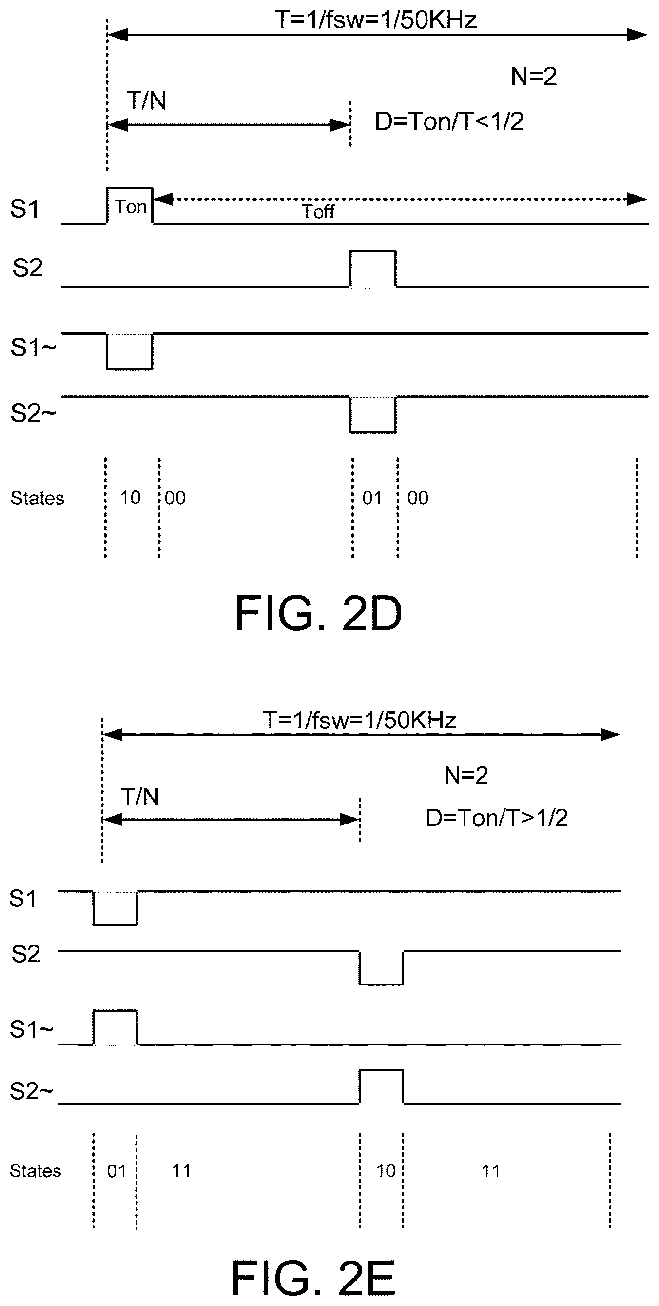
D00013

D00014

D00015

D00016

D00017

D00018

D00019
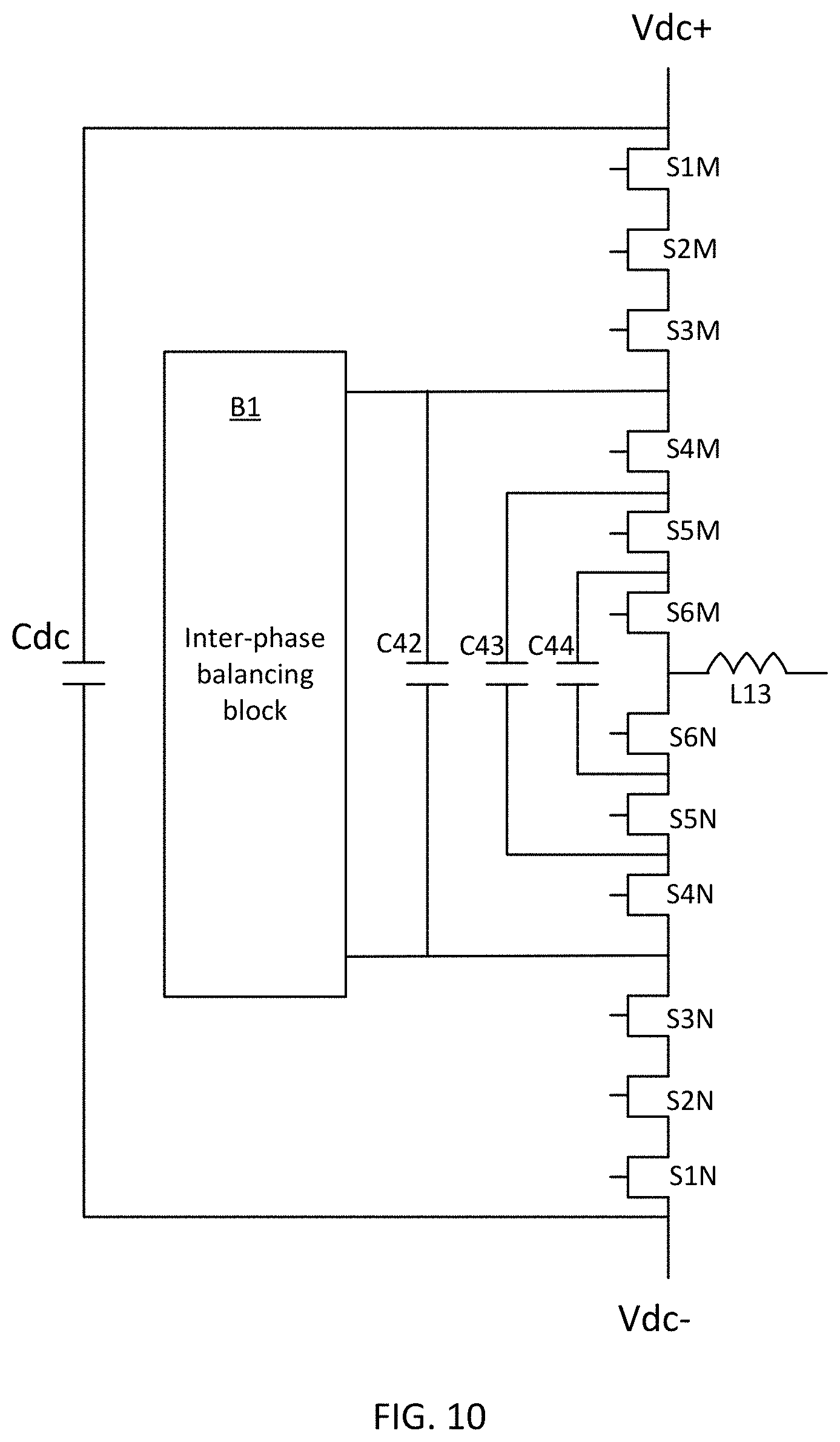
D00020

D00021
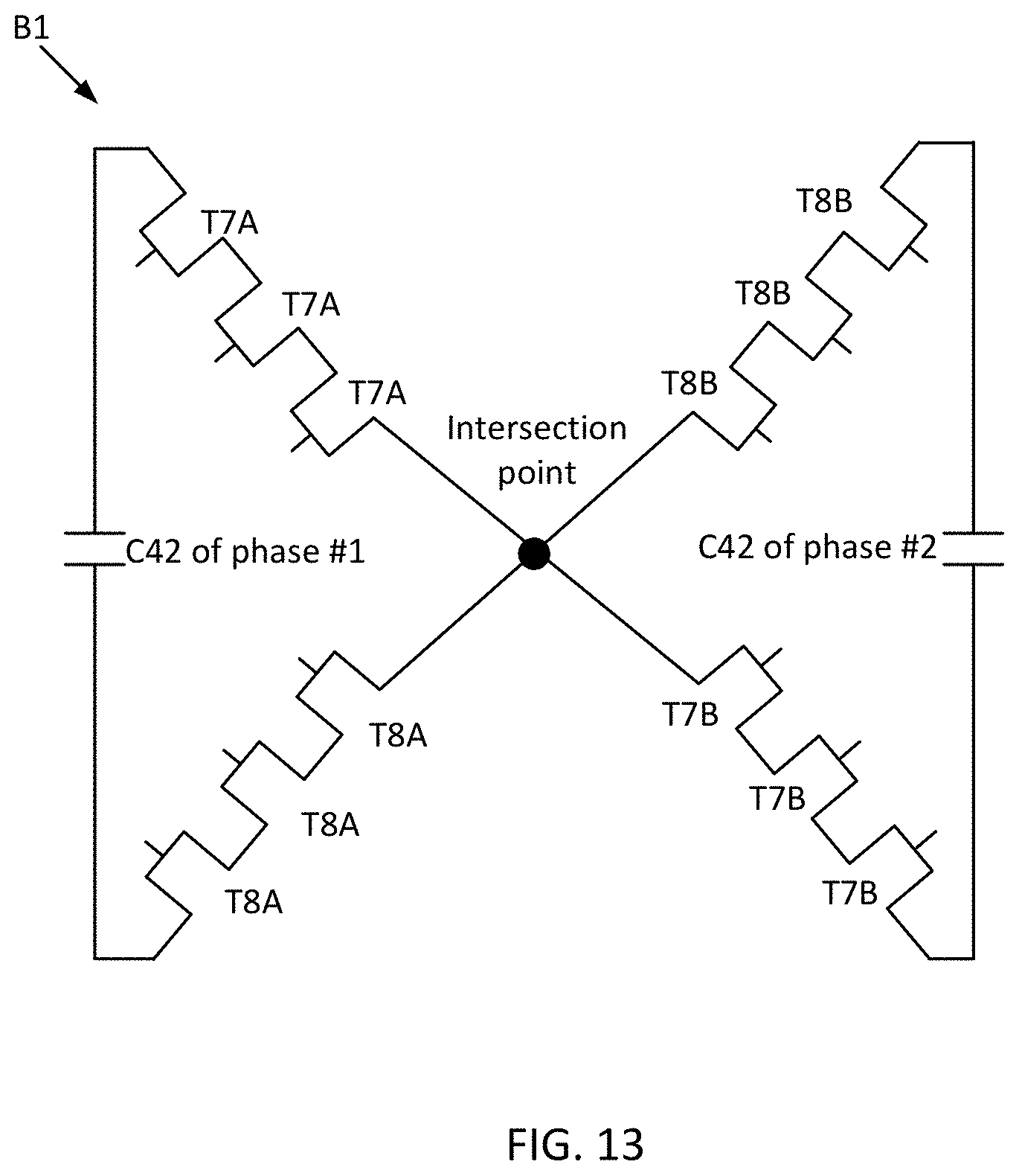
D00022

D00023

D00024

D00025
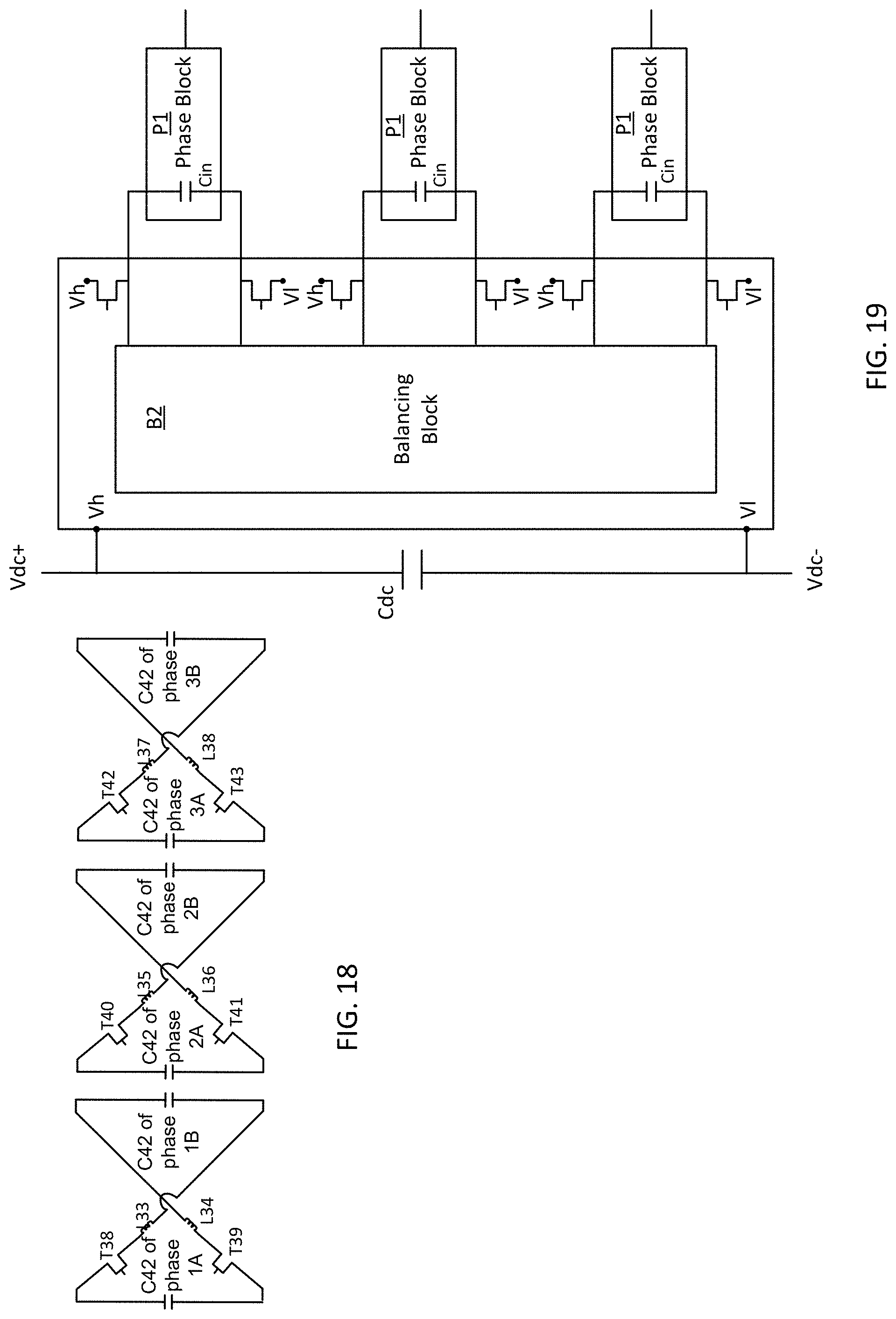
D00026

D00027
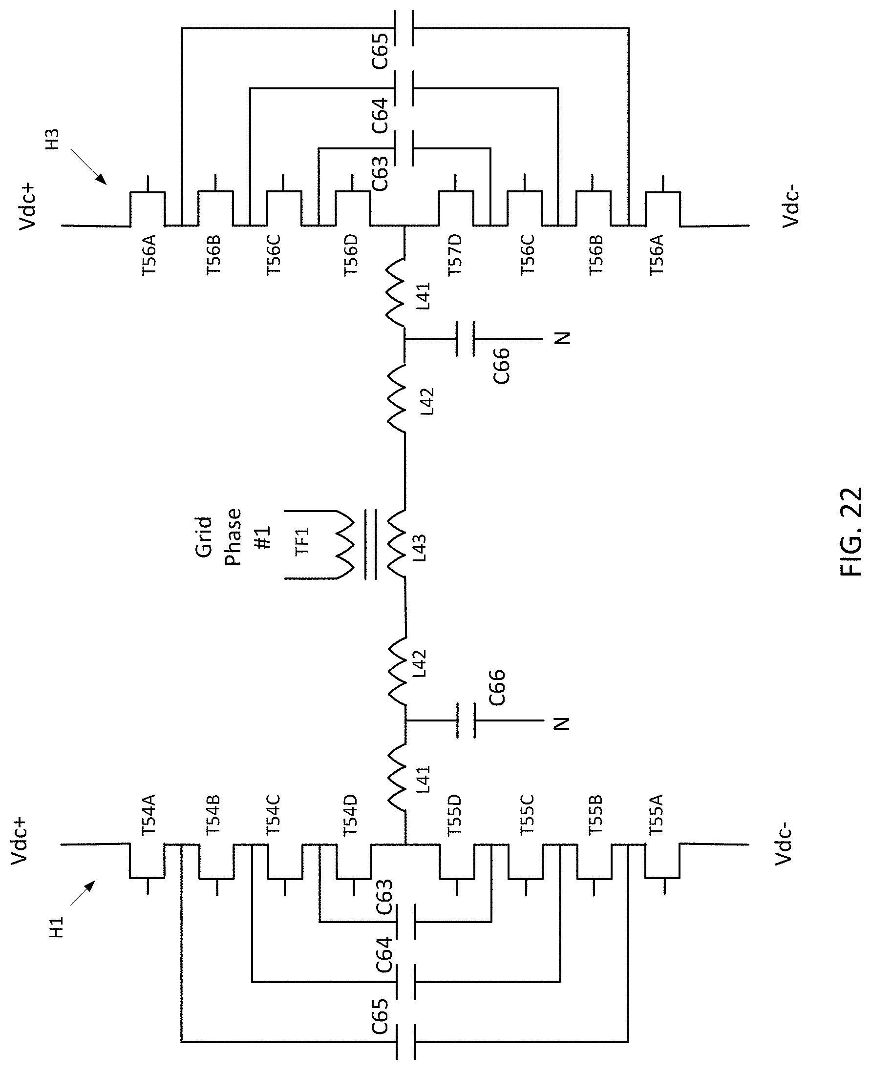
D00028
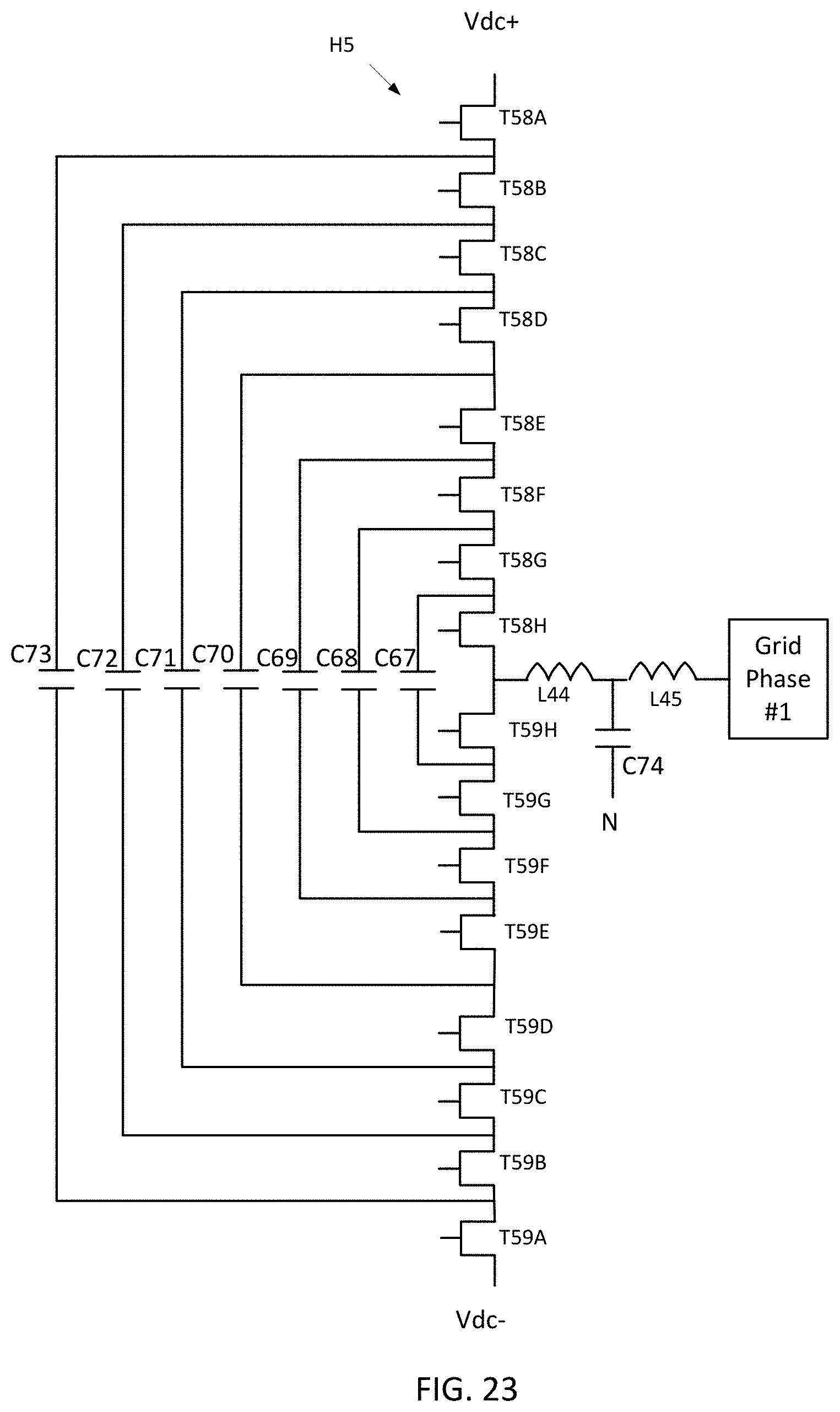
D00029

D00030
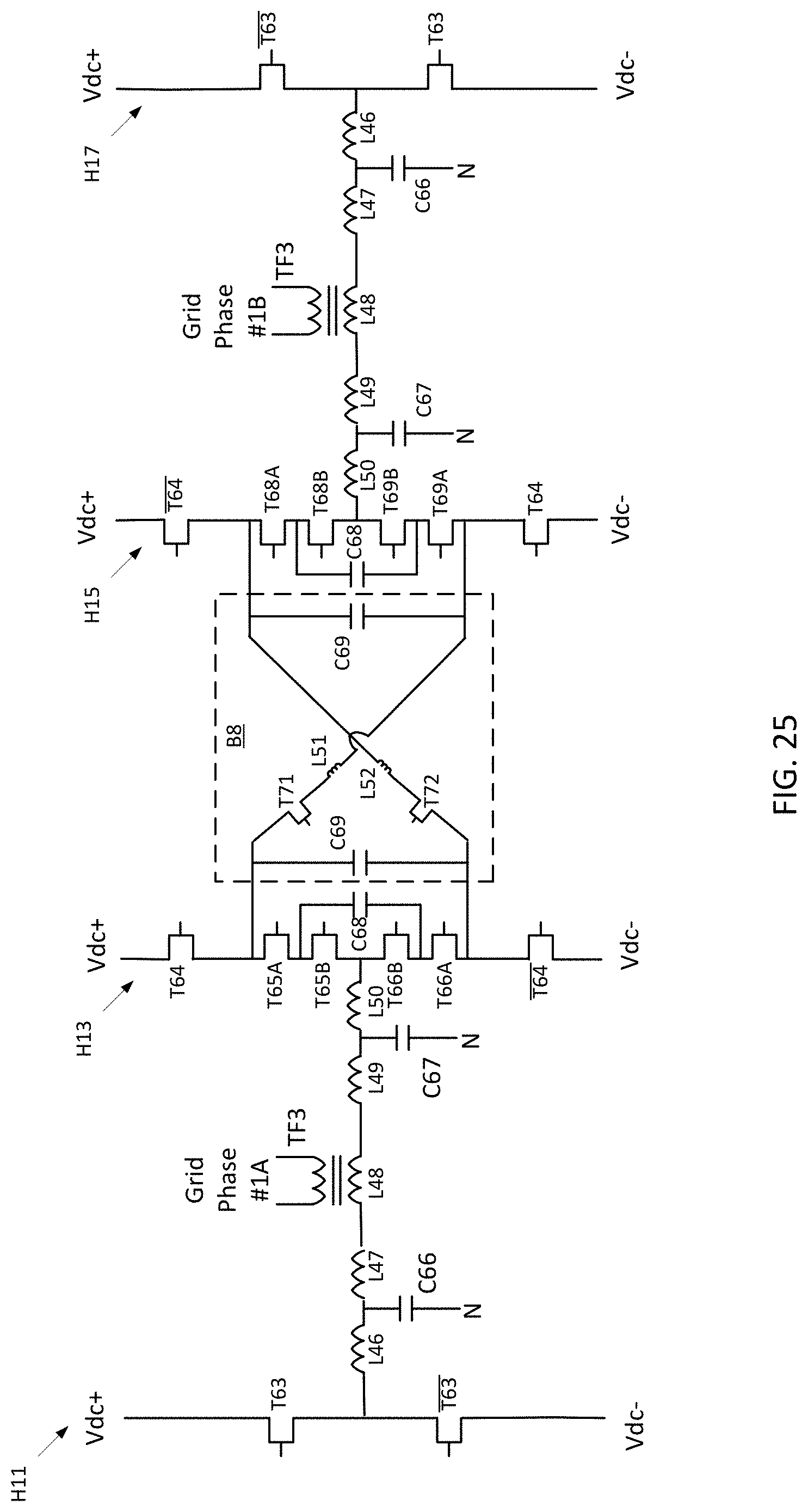
D00031

D00032

D00033
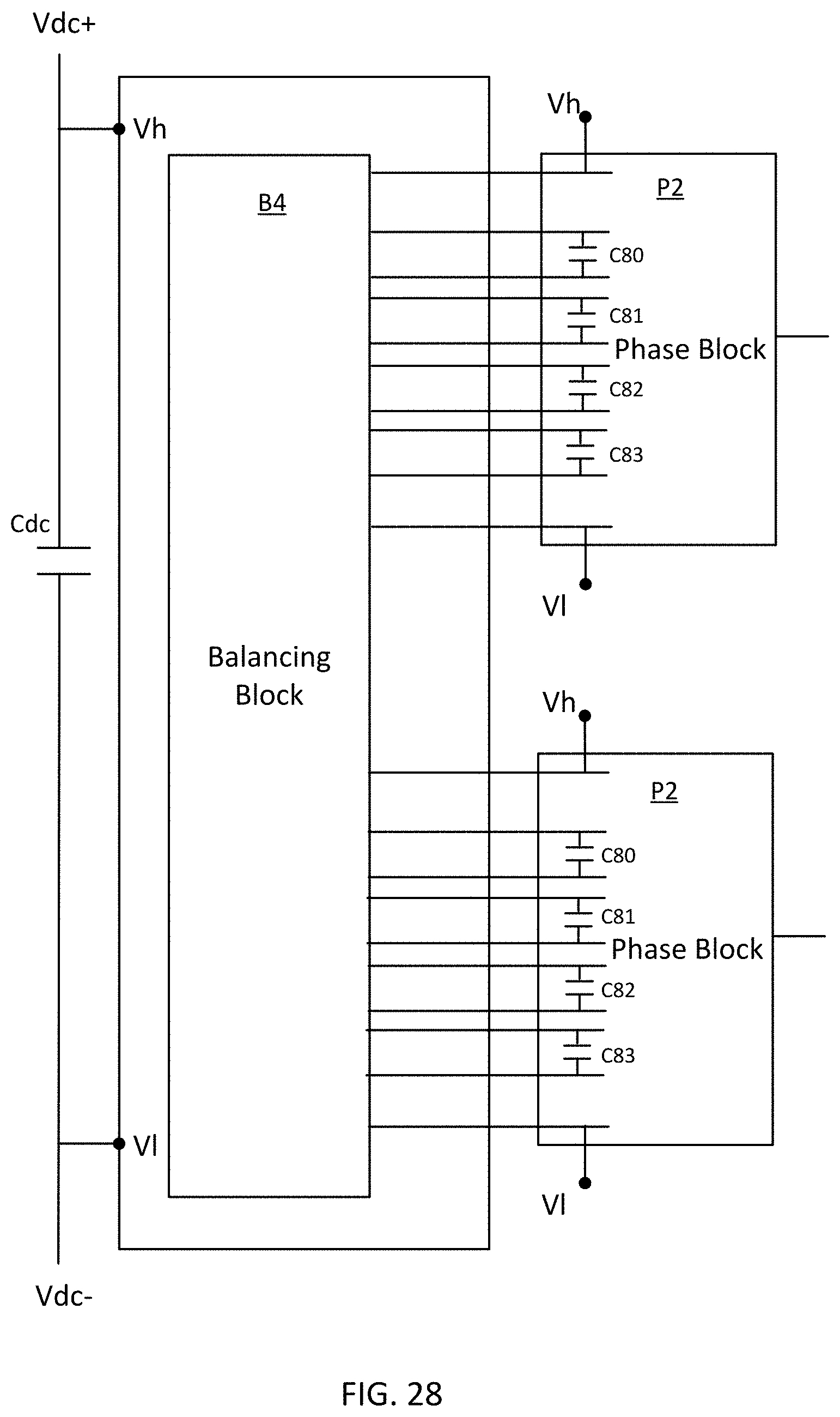
D00034

D00035
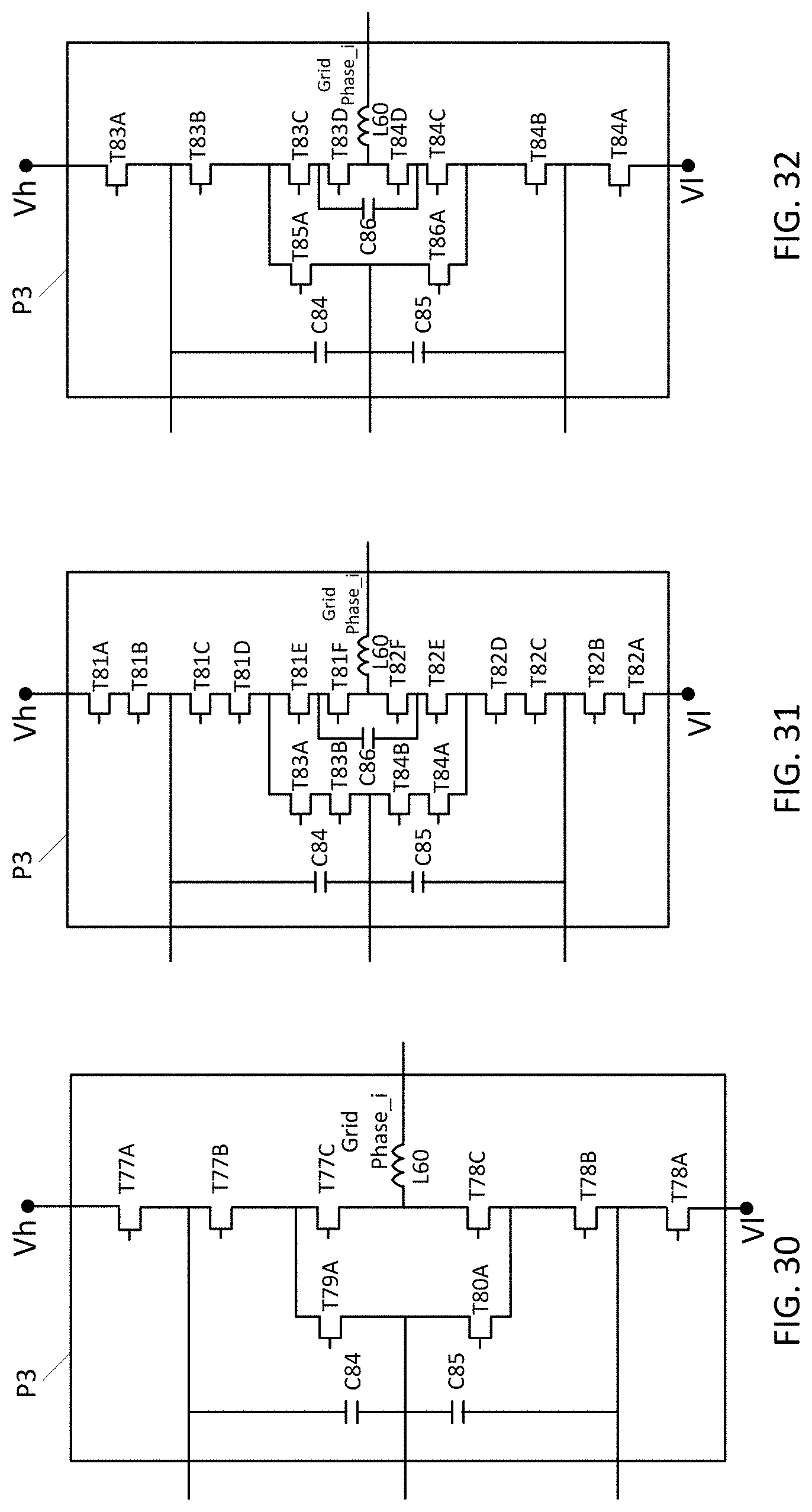
D00036
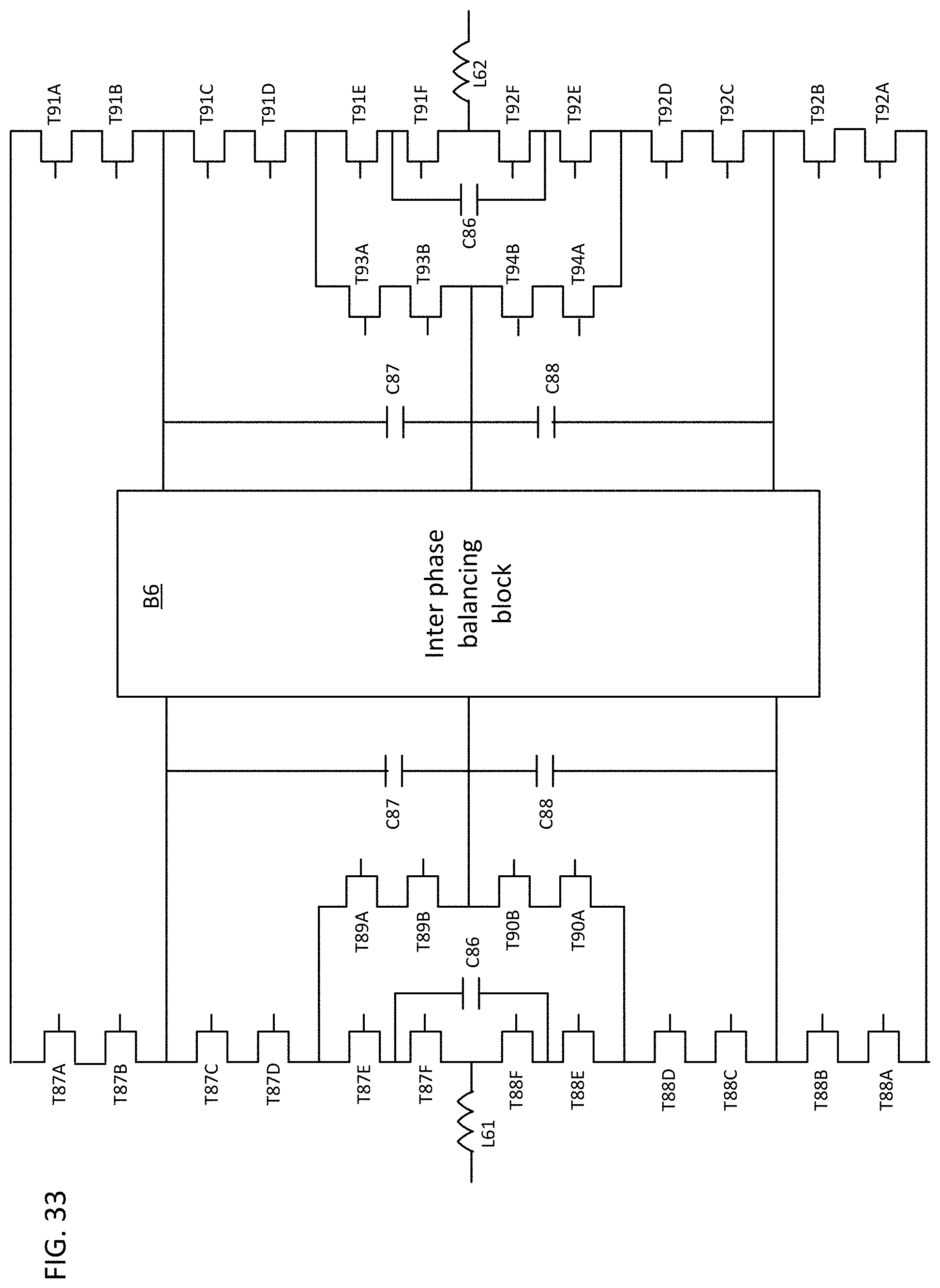
D00037
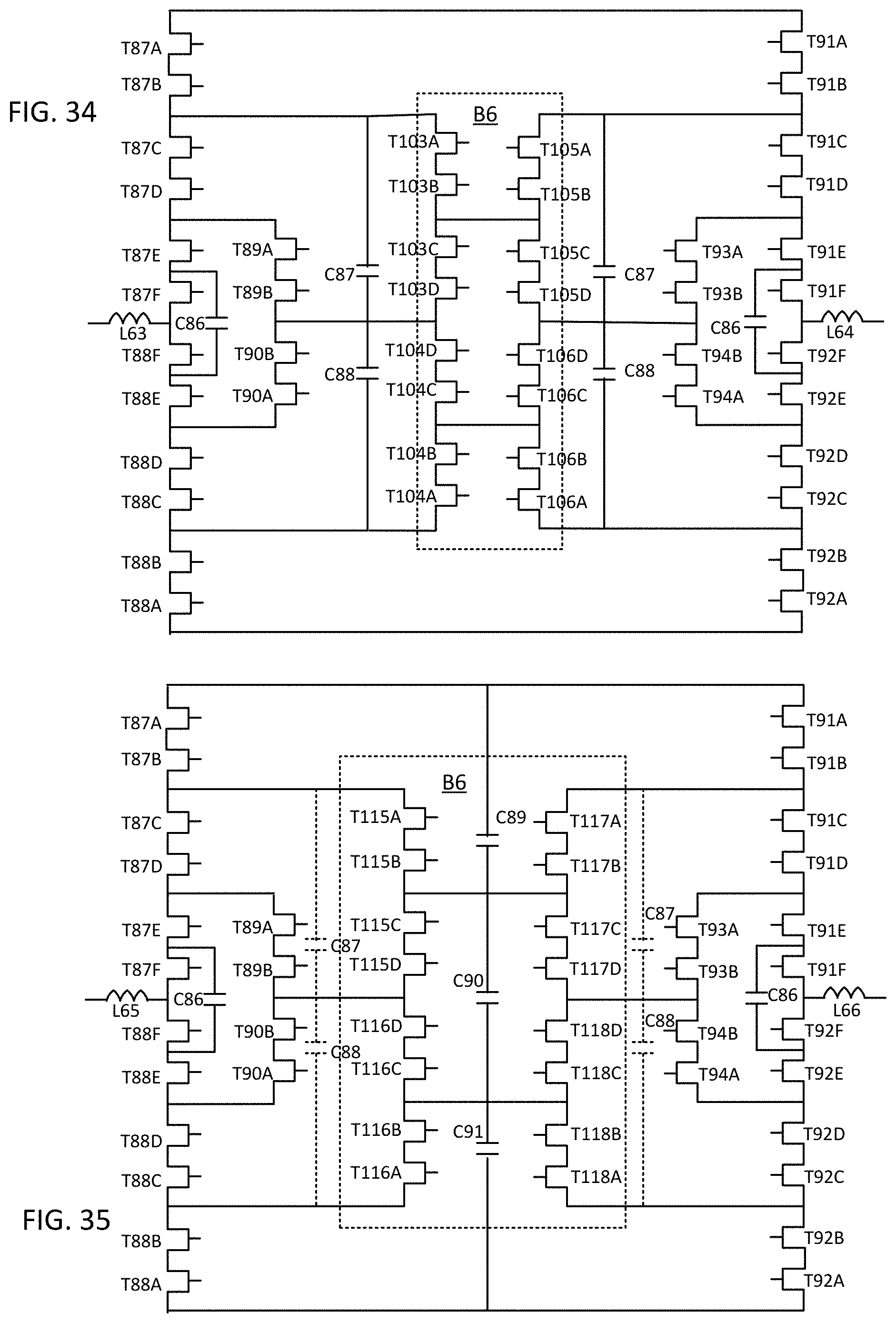
D00038

D00039

D00040
D00041
D00042
D00043

D00044

D00045

D00046

XML
uspto.report is an independent third-party trademark research tool that is not affiliated, endorsed, or sponsored by the United States Patent and Trademark Office (USPTO) or any other governmental organization. The information provided by uspto.report is based on publicly available data at the time of writing and is intended for informational purposes only.
While we strive to provide accurate and up-to-date information, we do not guarantee the accuracy, completeness, reliability, or suitability of the information displayed on this site. The use of this site is at your own risk. Any reliance you place on such information is therefore strictly at your own risk.
All official trademark data, including owner information, should be verified by visiting the official USPTO website at www.uspto.gov. This site is not intended to replace professional legal advice and should not be used as a substitute for consulting with a legal professional who is knowledgeable about trademark law.