Oil pump of vehicle having inner ring
Doo , et al. June 1, 2
U.S. patent number 11,022,134 [Application Number 16/355,043] was granted by the patent office on 2021-06-01 for oil pump of vehicle having inner ring. This patent grant is currently assigned to HYUNDAI MOTOR COMPANY, KIA MOTORS CORPORATION, MYUNG HWA IND. CO., LTD.. The grantee listed for this patent is Hyundai Motor Company, KIA Motors Corporation, MYUNG HWA IND. Co., Ltd.. Invention is credited to Jae-Kyun Doo, Hyun-Eu Jung, Kyung-Hwan Oh.


| United States Patent | 11,022,134 |
| Doo , et al. | June 1, 2021 |
Oil pump of vehicle having inner ring
Abstract
The present disclosure provides an oil pump including a housing in which a space is formed, a rotor installed to be rotatable in an eccentric position in the housing and having vanes mounted along a circumference direction to be protruded and retracted in a radial direction of the housing, and an inner ring fitted to an inner surface of the housing and rotated along with the rotor when the rotor rotates. The housing is formed of a material harder than the material of the inner ring, and oil for lubrication is provided between the housing and the inner ring.
| Inventors: | Doo; Jae-Kyun (Seoul, KR), Oh; Kyung-Hwan (Seoul, KR), Jung; Hyun-Eu (Hwaseong-si, KR) | ||||||||||
|---|---|---|---|---|---|---|---|---|---|---|---|
| Applicant: |
|
||||||||||
| Assignee: | HYUNDAI MOTOR COMPANY (Seoul,
KR) KIA MOTORS CORPORATION (Seoul, KR) MYUNG HWA IND. CO., LTD. (Seoul, KR) |
||||||||||
| Family ID: | 1000005589066 | ||||||||||
| Appl. No.: | 16/355,043 | ||||||||||
| Filed: | March 15, 2019 |
Prior Publication Data
| Document Identifier | Publication Date | |
|---|---|---|
| US 20190353178 A1 | Nov 21, 2019 | |
Foreign Application Priority Data
| May 18, 2018 [KR] | 10-2018-0057186 | |||
| Current U.S. Class: | 1/1 |
| Current CPC Class: | F04D 29/2266 (20130101); F01M 1/02 (20130101); F04D 29/2227 (20130101); F04D 29/2294 (20130101); F04D 29/247 (20130101); F04D 29/2238 (20130101); F01M 2001/0238 (20130101) |
| Current International Class: | F04D 29/22 (20060101); F01M 1/02 (20060101); F04D 29/24 (20060101) |
References Cited [Referenced By]
U.S. Patent Documents
| 3758859 | September 1973 | Damijonaitis |
| 3887035 | June 1975 | Hannibal |
| 3926281 | December 1975 | Hannibal |
| 4291651 | September 1981 | Villella |
| 4513215 | April 1985 | Del Serra |
| 4583926 | April 1986 | Mitsumori |
| 4998867 | March 1991 | Sakamaki |
| 5228334 | July 1993 | Stone |
| RE34473 | December 1993 | Ryan |
| 5273819 | December 1993 | Jex |
| 5501585 | March 1996 | Ogawa |
| 6183230 | February 2001 | Beardmore |
| 6276910 | August 2001 | Tsukamoto |
| 8398381 | March 2013 | Schumann |
| 9057266 | June 2015 | Viitamaki |
| 9115716 | August 2015 | Sekiya |
| 9127675 | September 2015 | Sekiya |
| 9382907 | July 2016 | Sekiya |
| 9388807 | July 2016 | Sekiya |
| 9399993 | July 2016 | Sekiya |
| 9458849 | October 2016 | Sekiya |
| 9683567 | June 2017 | Chikaoka |
| 2003/0072656 | April 2003 | Niwatsukino |
| 2004/0161355 | August 2004 | Dees |
| 2008/0000309 | January 2008 | Tsubouchi |
| 2008/0141921 | June 2008 | Hinderks |
| 2009/0068049 | March 2009 | Saito |
| 2009/0142221 | June 2009 | Strangman |
| 2012/0051955 | March 2012 | Hadar |
| 2013/0053210 | February 2013 | Kari |
| 2015/0285301 | October 2015 | Begin |
| 2017/0126087 | May 2017 | Soderberg |
| 2017/0159713 | June 2017 | Ito |
| 2017/0184099 | June 2017 | Watanabe |
| 2017/0204753 | July 2017 | Sacomori |
| 2018/0058450 | March 2018 | McGowan |
| 2018/0223835 | August 2018 | Maki |
| 2018/0274388 | September 2018 | Oh |
| 2020/0003209 | January 2020 | Eto |
| 2020/0080555 | March 2020 | Bennett, Sr. |
| 2020/0080561 | March 2020 | Hong |
| 2020/0153368 | May 2020 | Kobayashi |
| 416255 | Sep 1934 | GB | |||
| 60085284 | May 1985 | JP | |||
| 2012/0060098 | Jun 2012 | KR | |||
| 20120060098 | Jun 2012 | KR | |||
| WO-2019240436 | Dec 2019 | WO | |||
Other References
|
Phenolic Novolac And Resol Resins--Phenolic thermosetting resin Feb. 2014 (Year: 2014). cited by examiner . KR20120060098A Machine Translation (Year: 2012). cited by examiner. |
Primary Examiner: Nguyen; Ninh H.
Assistant Examiner: Delrue; Brian Christopher
Attorney, Agent or Firm: Brinks Gilson & Lione
Claims
What is claimed is:
1. An oil pump for a vehicle, the oil pump comprising: a housing forming a space; a rotor installed to be rotatable in an eccentric position in the housing, the rotor having vanes mounted along a circumferential direction to be protruded and retracted in a radial direction of the housing; and an inner ring fitted to an inner surface of the housing, the inner ring configured to rotate along with the rotor when the rotor rotates, wherein: a first groove is formed on the inner surface of the housing along the circumferential direction of the housing, a second groove is formed on an outer surface of the inner ring along the circumferential direction, the first groove and the second groove are configured to flow oil between the inner ring and the housing and reduce a friction between the inner ring and the housing, the housing is formed of a material harder than the inner ring, the inner ring is configured to rotate in the same direction as the vanes rotate when the rotor rotates, and the inner ring is configured to rotate along with the vanes when the vanes rotate, and the inner ring is configured to rotate later than the rotor.
2. The oil pump of claim 1, wherein the housing is made of synthetic resin material.
3. The oil pump of claim 2, wherein the housing is made of thermosetting phenolic resin material.
4. The oil pump of claim 1, wherein the housing is made of a light metal having a specific gravity lower than gravity of steel.
5. The oil pump of claim 1, wherein the inner ring is made of the same material as the vanes.
6. The oil pump of claim 1, wherein the housing is provided with at least an oil supply hole for supplying oil between the inner surface of the housing and the inner ring.
7. The oil pump of claim 1, wherein an outer surface of the housing is provided with at least one pocket formed concavely from the outside of the housing to the inner surface of the housing.
8. The oil pump of claim 7, wherein the at least one pocket comprises a plurality of pockets that is formed along the circumferential direction and a height direction of the housing.
9. The oil pump of claim 1, wherein the vanes are slidable in the radial direction and installed at intervals along the circumferential direction.
10. The oil pump of claim 1, wherein the inner ring is formed in a cylinder shape to be fitted to the inner surface of the housing.
11. The oil pump of claim 1, wherein the first groove is formed in a spiral pattern on the inner surface of the housing and configured to supply the oil between the housing and the inner ring.
Description
CROSS-REFERENCE TO RELATED APPLICATION
This application claims priority to and the benefit of Korean Patent Application No. 10-2018-0057186, filed on May 18, 2018, which is incorporated herein by reference in its entirety.
FIELD
The present disclosure relates to an oil pump for pressurizing engine oil of a vehicle.
BACKGROUND
The statements in this section merely provide background information related to the present disclosure and may not constitute prior art.
An engine mounted on a vehicle circulates engine oil for reducing the friction of each moving part and for cooling. The engine oil is pressurized by an oil pump mounted inside the engine and supplied to the lubrication parts.
As a prior art, an oil pump structure is shown in FIG. 1. The oil pump 110 includes a housing 111 in which a space is formed, a rotor 112 which is eccentrically rotated inside the housing 111, and vanes 113 which are slidable in the radial direction of the rotor 112 and installed at intervals along the circumferential direction of the rotor 112. Since the vanes 113 are installed so that the front ends of the vanes 113 are in close contact with the inner surface of the housing 111, the oil is compressed by the volume change of the space between the inner surface of the housing 111 and the vanes 113 adjacent to the outer surface of the rotor 112 and each other when the rotor 112 rotates.
However, in the oil pump 110 according to the prior art as described above, since the vanes 113 are rotated by the rotor 112 and simultaneously performs a sliding motion with respect to the rotor 112, it is found that the moving parts of the oil pump 110 are abruptly abraded when the rotation speed of the oil pump 110 is increased.
The inner surface of the housing 111 is nitriding-treated, the vane 113 is made of tool steel, and the outer surface of the rotor 112 is also steam-treated.
In recent years, the engine has been upgraded to high performance, so that the oil pump 110 is often operated under severe conditions, thereby promoting abrasion.
The foregoing is intended merely to aid in the understanding of the background of the present disclosure, and is not intended to mean that the present disclosure falls within the purview of the related art that is already known to those skilled. The above information disclosed in this Background section is only for enhancement of understanding of the background of the present disclosure, and therefore it may contain information that does not form the prior art that is already known to a person of ordinary skill in the art.
SUMMARY
The present disclosure provides an oil pump having an inner ring in which the material of a housing is replaced by a lightweight material, and the rotatable inner ring is provided at an inner surface of the housing to be contacted with vanes.
An oil pump according to a form of the present disclosure may include a housing in which a space is formed, a rotor installed to be rotatable in an eccentric position on the housing and having vanes mounted along a circumferential direction to be protruded and retracted in a radial direction of the housing, and an inner ring fitted to an inner surface of the housing and rotated along the rotor when the rotor rotates. The housing is formed of a material harder than the inner ring, and oil for lubrication is provided between the housing and the inner ring.
The housing may be made of synthetic resin material. In particular, the housing may be made of thermosetting phenolic resin material.
According to other form of the present disclosure, the housing may be made of a light metal having a specific gravity lower than that of steel. In particular, the housing may be made of aluminum or magnesium.
The inner ring may be made of metal material. In particular, the inner ring may be made of the same material as the vane. Accordingly, the inner ring may be made of bearing steel or tool steel.
According to further aspect of the present disclosure, at least one of an outer circumference surface of the inner ring and an inner surface of the housing may be formed with at least one groove for accommodating oil between the inner ring and the housing.
The groove may be formed on the inner surface of the housing as a first groove along the circumference of the housing.
The groove may be formed on the outer circumference surface of the inner ring as a second groove along the circumference of the inner ring.
The housing may be provided with at least one oil supply hole for supplying oil between the inner surface of the housing and the inner ring.
The outer surface of the housing may be provided with at least one pocket formed concavely from the outside of the housing to the inner surface of the housing. The pockets may be formed along the circumference direction and the height direction of the housing.
In accordance with the form of the present disclosure, the oil pump includes the housing made of synthetic resin material so that it can be lightweight. Furthermore, the inner surface of the housing is contacted to the inner ring having excellent abrasion resistance, thereby improving abrasion resistance.
In addition, since the housing is made of synthetic resin material, it is possible to form the housing shapes as desired to reduce Noise, Vibration and Harshness (NVH). For example, pockets on the outer surface of the housing can be easily formed.
Further areas of applicability will become apparent from the description provided herein. It should be understood that the description and specific examples are intended for purposes of illustration only and are not intended to limit the scope of the present disclosure.
DRAWINGS
In order that the disclosure may be well understood, there will now be described various forms thereof, given by way of example, reference being made to the accompanying drawings, in which:
FIG. 1 is a plane view of an oil pump according to a prior art;
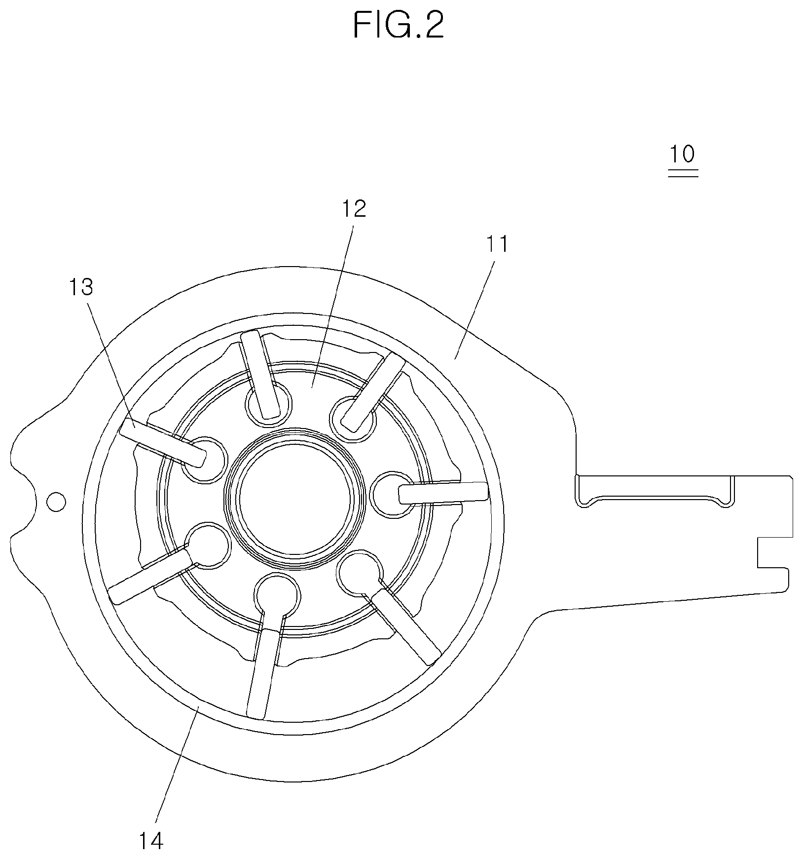
FIG. 2 is a plan view showing an oil pump with an inner ring according to an exemplary form of the present disclosure;
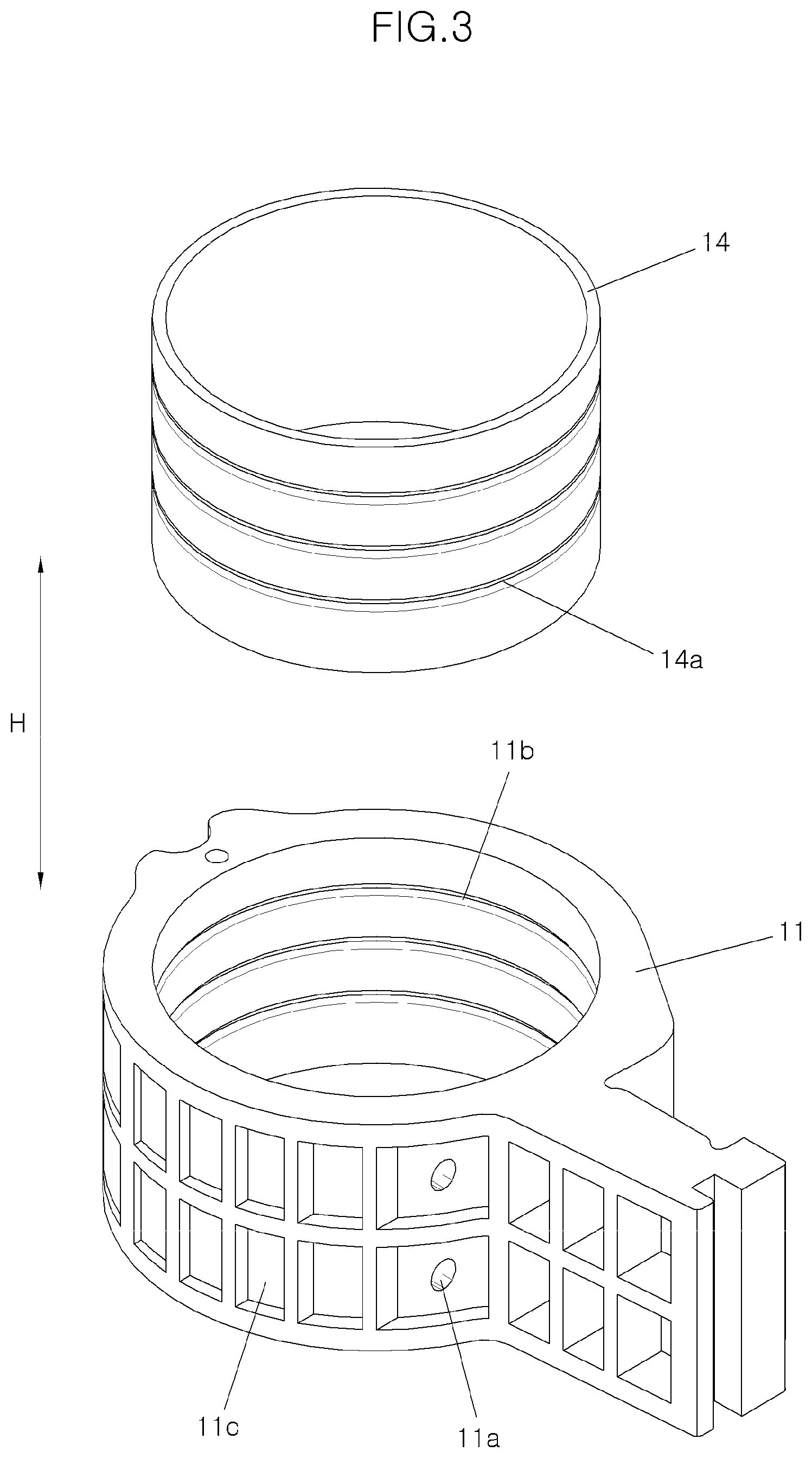
FIG. 3 is an exploded perspective view of a housing and an inner ring in the oil pump according to the exemplary form of the present disclosure;
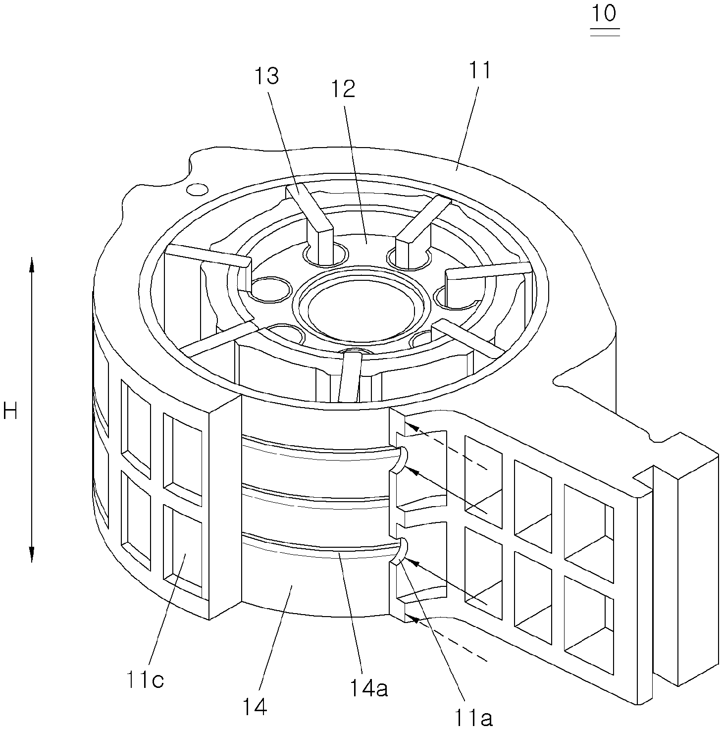
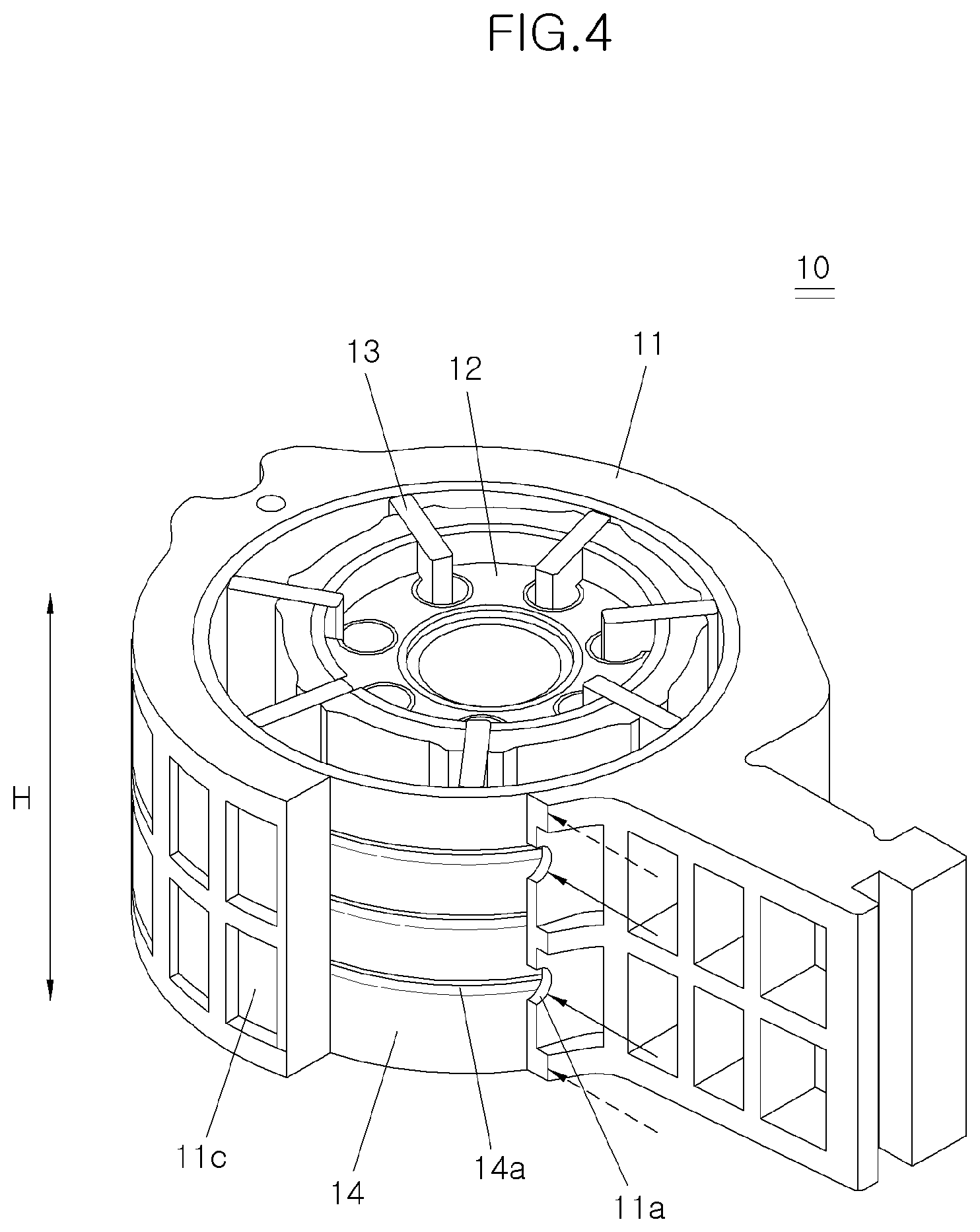
FIG. 4 is a partially cut-away perspective view of the oil pump according to the exemplary form of the present disclosure; and
FIG. 5 is a perspective view of a groove with a spiral shape formed in a housing of an oil pump according to another exemplary form of the present disclosure.
The drawings described herein are for illustration purposes only and are not intended to limit the scope of the present disclosure in any way.
DETAILED DESCRIPTION
The following description is merely exemplary in nature and is not intended to limit the present disclosure, application, or uses. It should be understood that throughout the drawings, corresponding reference numerals indicate like or corresponding parts and features.
Referring to FIG. 2, an oil pump 10 having an inner ring 14 according to the present disclosure may include a housing 11 in which a space is formed, a rotor 12 being installed to be rotatable in an eccentric position on the housing 11 and having vanes 13 mounted along a circumference direction to be protruded and retracted in a radial direction of the housing 11, and the inner ring 14 which is fitted to an inner surface of the housing 11 and rotates along the rotor 12 when the rotor 12 rotates. The housing 11 may be formed of a material harder than the inner ring 14, and oil for lubrication may be accommodated between the housing 11 and the inner ring 14.
The space may be formed in the housing 11. Constituent elements described below may be provided in the space of the housing 11.
The rotor 12 may be installed to be rotatable in an eccentrically located position on the housing 11 and have the vane 13 mounted along a circumference direction to be protruded and retracted in a radial direction of the housing 11.
The inner ring 14 may be fitted to the inner surface of the housing 11. The inner ring 14 may rotate along the rotor 12 when the rotor 12 rotates. The inner ring 14 may be contact with the rotating vane 13 and formed into a cylinder shape to be fitted to the inner surface of the housing 11.
As shown in FIG. 2, when the rotor 12 rotates, the inner ring 14 may rotate in the same direction as the vane 13. Since the inner ring 14 rotates along the vane 13 when the vane 13 rotates, the inner ring 14 rotates at a later rotation speed than the rotor 12.
The inner ring 14 and the housing 11 may be the duality structure, so that the fixed housing 11 may be formed of lightweight material and the inner ring 14 directly contacting with the rotating vane 13 may be formed of a material having a higher strength than the housing 11. More specifically, the housing 11 may be formed of synthetic resin or light metal material, and the housing 11 may be made of thermosetting phenolic resin material in synthetic resin and also, a light metal having a specific gravity lower than that of steel, for example, aluminum or magnesium.
The inner ring 14 may be made of material that is stronger than the housing 11, for example steel. Preferably, the inner ring 14 may made of bearing steel or tool steel that is the same material as the vane 13 because the vane 13 may also be made of bearing steel or tool steel. The bearing steel and tool steel have excellent abrasion resistance, which can reduce the abrasion between the vane 13 and the inner ring 14 contacted with each other.
Accordingly, since the housing 11 is made of a lightweight material and the inner ring 14 contacting the vane 13 is made of a high-strength material, the weight of the oil pump 10 can be reduced and fuel consumption can be improved.
When the rotor 12 rotates with the inner ring 14 together, lubrication is desired between the housing 11 and the inner ring 14. For this purpose, an oil film is formed to contain oil between the housing 11 and the inner ring 14.
Particularly, in FIG. 3, at least one first groove 11b is formed on the inner surface of the housing 11 along a height direction H and at least one second groove 14a is formed on an outer circumference surface of the inner ring 14 along the height direction H. When the oil pump 10 is assembled according to the present disclosure, at least one of the first groove 11b in the housing 11 and second groove 14a in the inner ring 14 may be formed for receiving oil. Since the oil is provided inside each of the grooves 11b and 14a, friction between the inner ring 14 and the housing 11 is reduced by the oil while the inner ring 14 rotates in the housing 11.
For example, as shown in FIG. 3, the first groove 11b may be formed on the inner surface of the housing 11. The first groove 11b may be formed along the circumference direction of the housing 11 at a predetermined depth. In FIG. 3, a plurality of the first grooves 11b in the housing 11 may be formed along the height direction H of the housing 11.
On the other hand, the second groove 14a may also be formed on the outer circumference surface of the inner ring 14. A plurality of second grooves 14a in the inner ring 14 may also be formed along the height direction H of the inner ring 14.
The housing 11 may be provided with at least one oil supply hole 11a for supplying oil desired for lubrication between the housing 11 and the inner ring 14. The oil supply holes 11a may be formed through the wall of the housing 11 so that oil is supplied from the outside of the housing 11 to the inner surface of the housing 11 for lubricating between the housing 11 and the inner ring 14.
The oil may also be supplied through the surface where the oil pump 10 is assembled. FIG. 4 shows the area where the oil is supplied for the lubrication of the oil pump 10 by arrows. The oil may be supplied through the oil supply hole 11a (solid line in FIG. 4) and also be supplied through the surface on which the oil pump 10 is assembled (dotted arrow in FIG. 4).
On the outer surface of the housing 11, at least one pocket 11c may be formed concavely from the outer surface of the housing 11 along the circumference direction and the height direction H of the housing 11.
The pockets 11c are configured for serving to buffer the pressure wave generated by the oil pressurized by and discharged from the oil pump 10 during operation of the oil pump 10. These pockets 11c may be formed in the housing 11 along the circumference direction and the height direction H of the housing 11 for buffering the pressure wave generated when the pressurized oil is discharged from the oil pump 10, thereby improving NVH (Noise, Vibration and Harshness) performance.
FIG. 5 shows an oil pump housing having an inner ring (not shown) according to another exemplary form of the present disclosure.
The present exemplary form has the same configuration as the oil pump described above except that another groove 21b of the housing 21 is formed in a different shape. As shown in FIG. 5, the groove 21b formed in the housing 21 may be formed in a spiral pattern along the inner surface of the housing 21 to supply oil between the housing 21 and the inner ring (not shown). Furthermore, the groove 21b with a spiral shape may also be formed in the inner ring (not shown).
While this present disclosure has been described in connection with what is presently considered to be practical exemplary forms. It is to be understood that the present disclosure is not limited to the disclosed forms, but, on the contrary, it is intended to cover various modification and equivalent arrangements included within the spirit and scope of the present disclosure.
* * * * *
D00000
D00001
D00002
D00003
D00004
D00005
XML
uspto.report is an independent third-party trademark research tool that is not affiliated, endorsed, or sponsored by the United States Patent and Trademark Office (USPTO) or any other governmental organization. The information provided by uspto.report is based on publicly available data at the time of writing and is intended for informational purposes only.
While we strive to provide accurate and up-to-date information, we do not guarantee the accuracy, completeness, reliability, or suitability of the information displayed on this site. The use of this site is at your own risk. Any reliance you place on such information is therefore strictly at your own risk.
All official trademark data, including owner information, should be verified by visiting the official USPTO website at www.uspto.gov. This site is not intended to replace professional legal advice and should not be used as a substitute for consulting with a legal professional who is knowledgeable about trademark law.