Lightweight Vacuum Pump With Oxidized Surfaces
Hong; Tinggui
U.S. patent application number 16/566594 was filed with the patent office on 2020-03-12 for lightweight vacuum pump with oxidized surfaces. This patent application is currently assigned to Fieldpiece Instruments, Inc.. The applicant listed for this patent is Fieldpiece Instruments, Inc.. Invention is credited to Tinggui Hong.
| Application Number | 20200080561 16/566594 |
| Document ID | / |
| Family ID | 69719121 |
| Filed Date | 2020-03-12 |


| United States Patent Application | 20200080561 |
| Kind Code | A1 |
| Hong; Tinggui | March 12, 2020 |
LIGHTWEIGHT VACUUM PUMP WITH OXIDIZED SURFACES
Abstract
A light weight vacuum pump is made with either or all of the stator, rotors and vanes made of aluminum or aluminum alloy that has been subjected to high energy oxidation, such as plasma electrolytic oxidation (PEO), electrolytic plasma oxidation (EPO) or micro-arc oxidation (MAO), to treat and harden the surface.
| Inventors: | Hong; Tinggui; (Orange, CA) | ||||||||||
| Applicant: |
|
||||||||||
|---|---|---|---|---|---|---|---|---|---|---|---|
| Assignee: | Fieldpiece Instruments,
Inc. Orange CA |
||||||||||
| Family ID: | 69719121 | ||||||||||
| Appl. No.: | 16/566594 | ||||||||||
| Filed: | September 10, 2019 |
Related U.S. Patent Documents
| Application Number | Filing Date | Patent Number | ||
|---|---|---|---|---|
| 62729199 | Sep 10, 2018 | |||
| Current U.S. Class: | 1/1 |
| Current CPC Class: | F04C 25/02 20130101; F04C 2230/41 20130101; F04C 13/008 20130101; F04C 29/025 20130101; F04C 29/04 20130101; F04C 18/344 20130101 |
| International Class: | F04C 29/04 20060101 F04C029/04; F04C 29/02 20060101 F04C029/02; F04C 25/02 20060101 F04C025/02; F04C 13/00 20060101 F04C013/00 |
Claims
1. A vacuum pump system comprising: a motor; and a vacuum pump operably connected to the motor, the vacuum pump having one or more rotors and one or more stators formed from material selected from the group consisting of aluminum, aluminum alloy or sintered aluminum powder, wherein the one or more rotors and one or more stators are treated with a high energy oxidation process selected from the group consisting of plasma electrolytic oxidation, electrolytic plasma oxidation, micro-arc oxidation or spark discharge anodizing.
2. The vacuum pump system of claim 1 further comprising: a plurality of vanes operably connected to the one or more rotors wherein the plurality of vanes are formed of material selected from the group consisting of aluminum, aluminum alloy or sintered aluminum powder, and wherein the plurality of vanes are treated with a high energy oxidation process selected from the group consisting of plasma electrolytic oxidation, electrolytic plasma oxidation, micro-arc oxidation or spark discharge anodizing.
3. The vacuum pump system of claim 1 further comprising: a plurality of vanes operably connected to the one or more rotors wherein the plurality of vanes are formed of material selected from the group consisting of untreated polymer, carbon or graphite.
4. The vacuum pump system of claim 1 further comprising: an oil pump operatively connected to one of the one or more rotors.
5. The vacuum pump system of claim 1 further comprising: an oil tank configured to submerge the vacuum pump in oil during operation.
6. A vacuum pump comprising: a stator having a cylindrical volute with a cylindrical inner wall, a first end wall and a second end wall; a rotor rotatably disposed within the stator, said rotor having an outer cylindrical surface; a vane coupled to the rotor and translatably disposed relative to the rotor, said vane having a sealing surface at a radial outer edge of said vane; wherein one or more of the stator, rotor or vane comprises a wear surface comprising aluminum, and at least one wear surface has a Vickers hardness in the range of 1000 to 3000 HV.
7. A vacuum pump system comprising: vacuum pump comprising: a stator having a cylindrical volute with a cylindrical inner wall, a first end wall and a second end wall; a rotor rotatably disposed within the stator, said rotor having an outer cylindrical surface; a vane coupled to the rotor and translatably disposed relative to the rotor, said vane having a sealing surface at a radial outer edge of said vane; wherein one or more of the stator, rotor or vane comprises a wear surface comprising aluminum, and at least one wear surface has a Vickers hardness in the range of 1000 to 3000 HV; a motor operably connected to the vacuum pump; wherein the rotor, stator or vane are formed from material selected from the group consisting of aluminum, aluminum alloy or sintered aluminum powder; wherein the rotor, stator and vane are treated with a high energy oxidation process selected from the group consisting of plasma electrolytic oxidation, electrolytic plasma oxidation, micro-arc oxidation or spark discharge anodizing.
8. The vacuum pump of claim 7 further comprising: an oil pump operatively connected to one of the one or more rotors.
9. The vacuum pump of claim 7 further comprising: an oil tank configured to submerge the vacuum pump in oil during operation.
Description
[0001] This application claims priority to U.S. Provisional Application 62/729,199, filed Sep. 10, 2018.
FIELD OF THE INVENTIONS
[0002] The inventions described below relate to the field of vacuum pumps.
BACKGROUND OF THE INVENTIONS
[0003] When the refrigerant tubing/piping of an Air Conditioning/Refrigeration (AC/R) system is exposed to atmosphere, air with water vapor and other contaminants may enter the tubing/piping. The moisture is highly damaging to refrigerant systems as it makes the refrigerant acidic which results in a corrosive environment that destroys system components and seals, and changes compressor oil to sludge. Cooling efficiency is degraded as pressures and temperatures vary greatly throughout the system. Compressor damage can occur and expansion valves can become clogged.
[0004] During installation of a new system or an open system repair, the refrigeration tubing/piping is exposed to ambient air, water vapor and/or other contaminants. After repair/installation and closure, the system needs to be cleared and checked for leaks to prevent loss of system efficiency over time. Before an AC/R system can be charged with refrigerant, the system must be arid, sanitary and sealed. The AC/R system should be evacuated to remove the water vapor and other contaminants and tested to ensure that a deep vacuum is held.
[0005] The most popular vacuum pump in the HVACR market is the rotary vane vacuum pump, which has a pump body/stator and a rotor made of one or more of cast iron, steel or powdered sintered steel. Cast iron, steel and powdered sintered steel are both high density materials that make vacuum pump systems very heavy. HVACR technicians often need to carry the vacuum pump system to the top of a building or some distance to reach the HVACR system. The typical vacuum pump system weight is about 30 pounds which represents a significant burden for HVACR technicians.
SUMMARY
[0006] The devices and methods described below provide for a lightweight vacuum pump with either or both of the stator and rotor made of aluminum, aluminum alloy, sintered powdered aluminum or any other suitable lightweight material that has been subjected to high energy oxidation to treat and harden the wear surfaces. Plasma electrolytic oxidation (PEO) which may also be called electrolytic plasma oxidation (EPO), micro-arc oxidation (MAO) or spark discharge anodizing is a high energy surface treatment that forms a deep and hard oxide layer on the lightweight metal. Alternatively, a lightweight vacuum pump may be made of any suitable powdered metallurgy aluminum alloy and at least the wear and bearing surfaces may be hardened with a suitable high energy oxidation process.
[0007] Optionally, only the stator and bearing surfaces may be treated with a suitable high energy surface treatment. Another option is for only the insert sleeves and sidewalls for each stage of the vacuum pump, and/or rotor surfaces may be treated with a suitable high energy surface treatment such as those described above.
[0008] The lightweight vacuum pump may be submerged in an oil tank such that the oil covers the pump. The oil bath will help trap contaminants, seal the gaps between stages and lubricate the components. The oil bath also conducts the heat from the pump to the oil and convection will cool the oil tank and pump.
BRIEF DESCRIPTION OF THE DRAWINGS
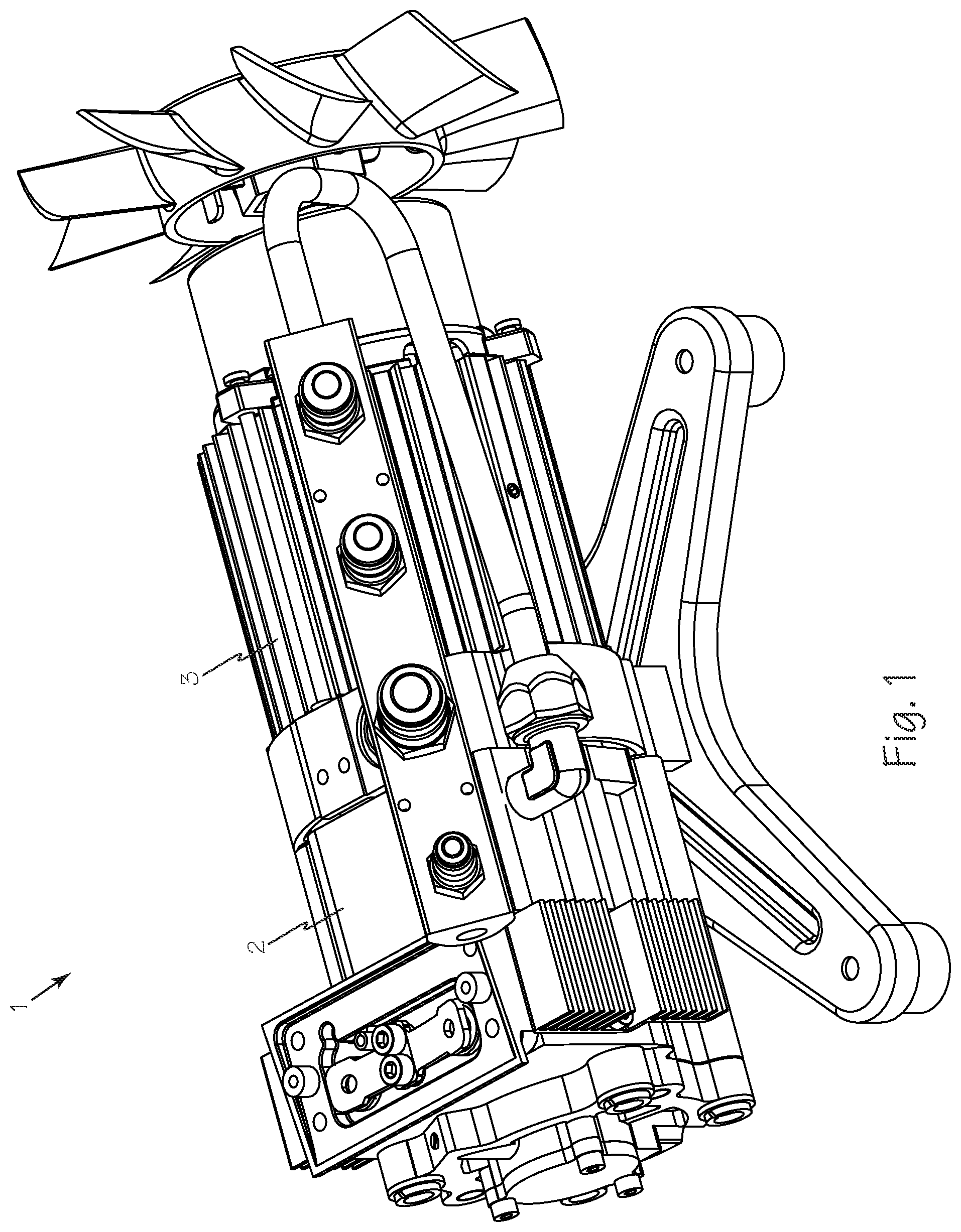
[0009] FIG. 1 is a perspective view of a vacuum pump system with the housing and oil reservoir removed for clarity.
[0010] FIG. 2 is a perspective view of a vacuum pump system with the oil reservoir.
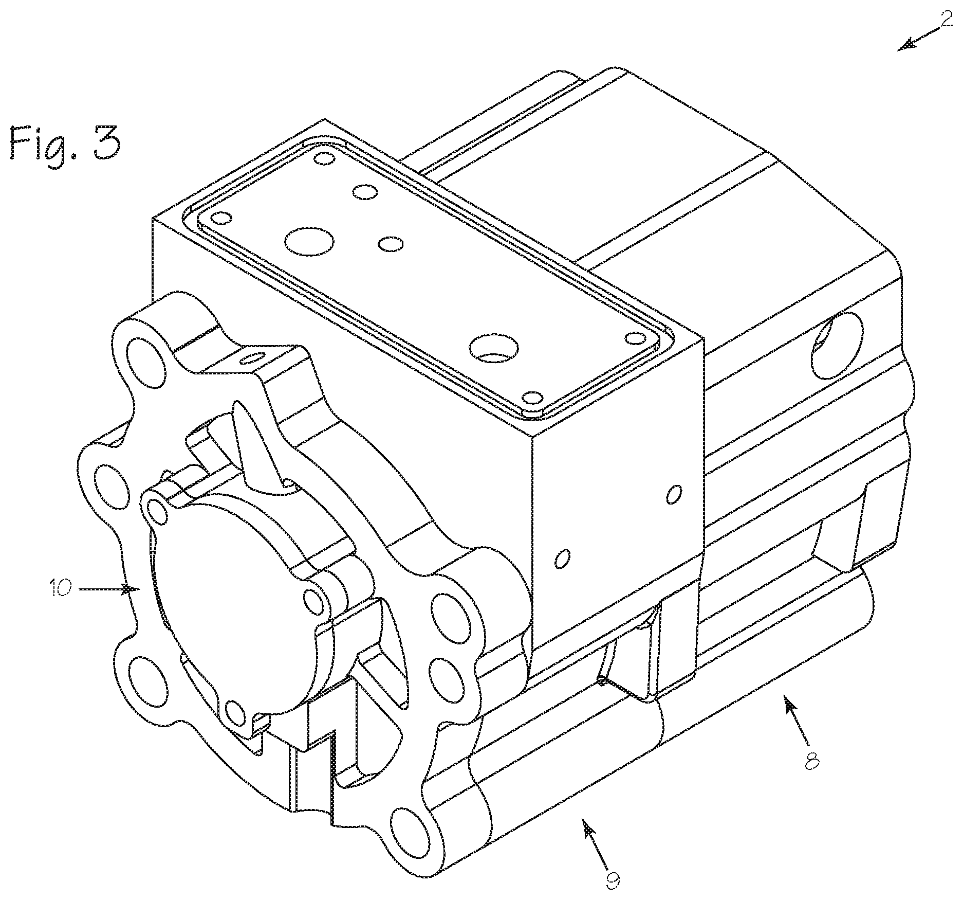
[0011] FIG. 3 is a perspective view of an aluminum vacuum pump casing with oxidized surfaces.
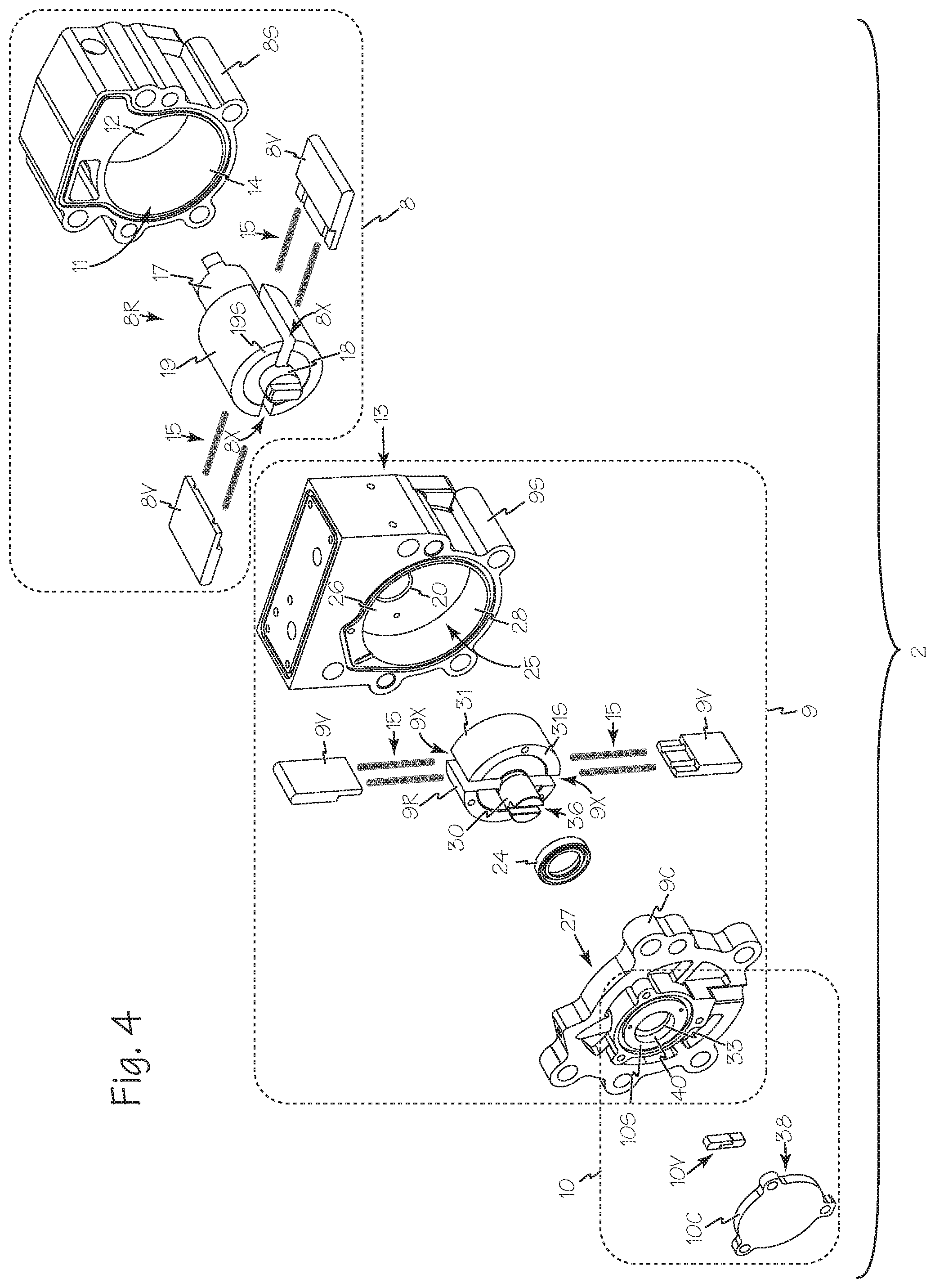
[0012] FIG. 4 is an exploded perspective view of the aluminum vacuum pump of FIG. 3.
[0013] FIG. 5 is an alternate exploded perspective view of the aluminum vacuum pump of FIG. 3.
[0014] FIG. 6 is a plan view of the bottom of the aluminum vacuum pump of FIG. 3.
[0015] FIG. 7 is a cross-section view of the aluminum vacuum pump of FIG. 6 taken along A-A.
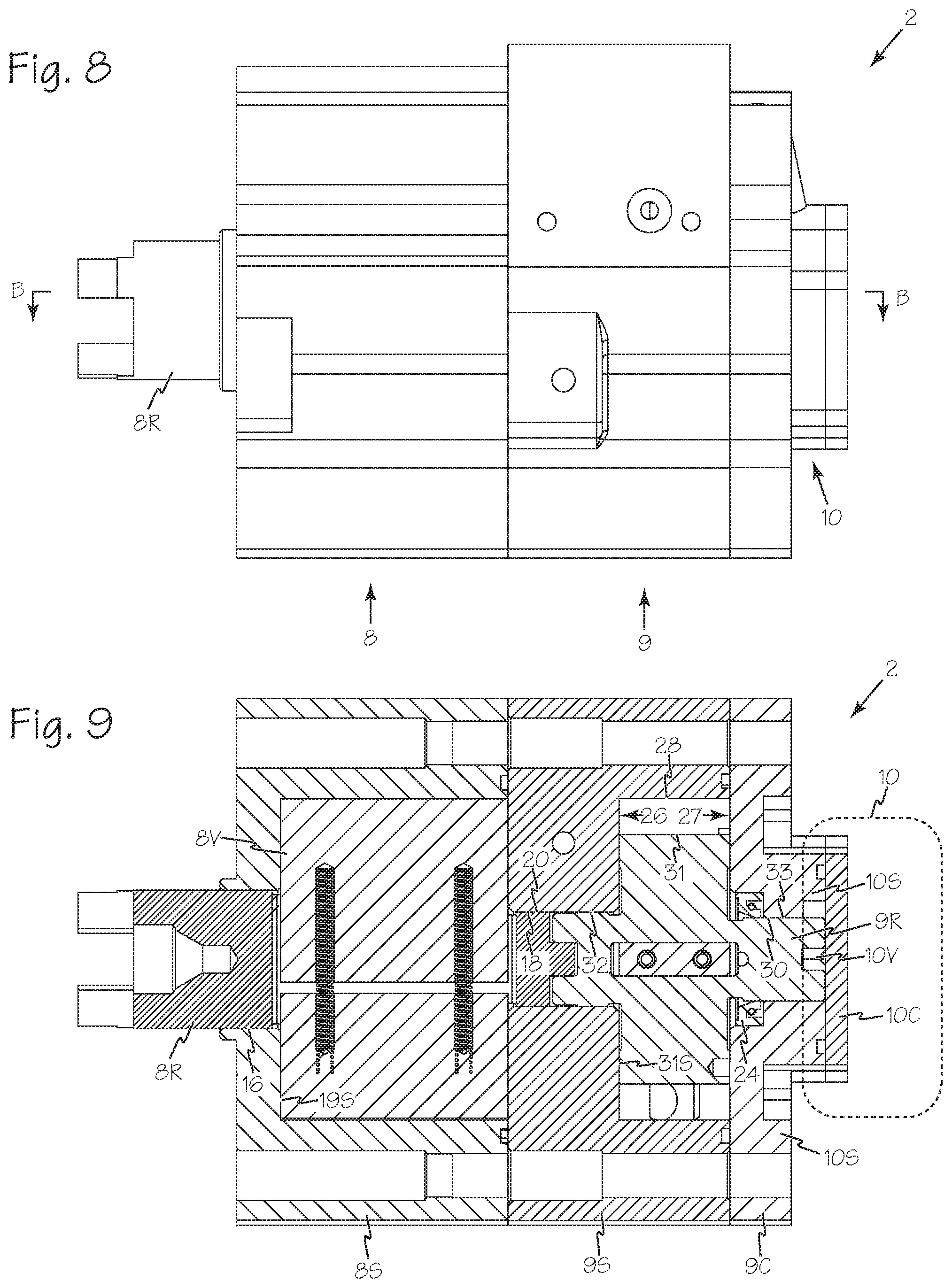
[0016] FIG. 8 is a plan view of the side of the aluminum vacuum pump of FIG. 3.
[0017] FIG. 9 is a cross-section view of the aluminum vacuum pump of FIG. 8 taken along B-B.
DETAILED DESCRIPTION OF THE INVENTIONS
[0018] FIG. 1 is a perspective view of a vacuum pump system 1 with the housing and oil reservoir not shown for clarity. The air-cooled aluminum vacuum pump 2 is operatively connected to motor 3. FIG. 2 is a perspective view of a vacuum pump system including the oil reservoir 4 secured to the aluminum vacuum pump 2.
[0019] FIG. 3 illustrates aluminum vacuum pump 2 as a rotary vane vacuum pump having a first stage 8, a second stage 9 and an optional integrated oil pump 10.
[0020] FIGS. 4 and 5 are exploded alternate perspective views of a light weight vacuum pump such as the aluminum vacuum pump 2. The first stage 8 includes the stator or housing 8S, rotor 8R and vanes 8V. The stator 8S and rotor 8R are formed of aluminum, aluminum alloy or sintered aluminum powder. The volute 11 of the first stage is enclosed by first side or end wall wear surface 12, second side or end wall wear surface 13 (visible in FIG. 5, which is part of the second stage stator or housing 9S, and the generally cylindrical inner wall of the volute, primary volute wear surface 14. The vanes 8V are biased by springs 15 to maintain contact with the inside or primary wear surface 14 of the first stage volute 11. The first and second side wear surfaces 12 and 13 as well as the primary volute wear surface 14 are treated with any suitable high energy oxidation process such as PEO, EPO, MAO, spark discharge anodizing or any other suitable high energy oxidation process. Bearing surfaces such as first stator bearing surface 16, first stage rotor bearing surfaces 17 and 18 as well as the outer cylindrical surface and side surfaces of the rotor, rotor wear surfaces 19 and 19S respectively, along with the second stage stator bearing surface 20 in the second stage housing may optionally be treated with any suitable high energy oxidation process.
[0021] Optionally, vanes such as first stage vanes 8V and second stage vanes 9V may also be formed of a suitable lightweight metal such as aluminum, aluminum alloy or sintered aluminum powder. Optionally, the vanes can be formed of untreated polymer, carbon, graphite or other suitable material. In this case, the vanes 8V and 9V as well as vane slots 8S and 9S may also be treated with any suitable high energy oxidation process as discussed above.
[0022] The second stage 9 includes the stator or housing 9S, rotor 9R, vanes 9V, seal 24 and cap 9C. The stator 9S and rotor 9R are formed of aluminum, aluminum alloy or sintered aluminum powder. The volute 25 of the second stage is enclosed by first side or end wall wear surface 26, second side or end wall wear surface 27 (visible in FIG. 5) of the second stage cap 9C, and the generally cylindrical inner wall of the volute, primary second stage volute wear surface 28. The vanes 9V are biased by springs 15 to maintain contact with the inside or primary wear surface 28 of the second stage volute 25. The side wear surfaces 26 and 27 as well as the primary volute wear surface 28 are treated with any suitable high energy oxidation process such as PEO, EPO, MAO, spark discharge anodizing or any other suitable high energy oxidation process. Bearing surfaces such as rotor bearing surfaces 30 and 32 on the second stage rotor and the outer cylindrical surface and side surfaces of the rotor, rotor wear surfaces 31 and 31S respectively, may also be treated with any suitable high energy oxidation process.
[0023] Optional oil pump 10 includes stator or housing 10S, vanes 10V and cap 10C. Vanes 10V engage a slot 36 in second stage rotor 9R. The wear surfaces of the oil pump volute, sides first and second side surfaces 37 and 38 as well as primary wear surface 40 are treated with any suitable high energy oxidation process such as PEO, EPO or MAO or any other suitable high energy oxidation process.
[0024] FIG. 6 is a plan view of the bottom of the aluminum vacuum pump 2 showing first stage 8, a second stage 9 and an optional integrated oil pump 10.
[0025] FIG. 7 is a cross-section view of the aluminum vacuum pump 2 and the optional oil pump 10 of FIG. 6 taken along A-A illustrating the interrelationship of the internal parts as well as the wear and bearing surfaces such as first stage bearing surface 18 and second stage stator bearing surface 20. The primary volute wear surface 14 and rotor wear surface 19 have close tolerances at interface 42 and must be hardened to prevent premature wear.
[0026] FIG. 8 is a plan view of the side of the aluminum vacuum pump 2 showing first stage 8, a second stage 9 and an optional integrated oil pump 10.
[0027] FIG. 9 is a cross-section view of the aluminum vacuum pump 2 and the optional oil pump 10 of FIG. 8 taken along B-B illustrating the interrelationship of the internal parts and wear surfaces such as first side wear surface 26, second side wear surface 27 and second stage rotor 9R. The bearing surface 30 of second stage rotor 9R engages seal 24 which in turn is engaged by second stage cap 9C.
[0028] Optionally, the inner generally cylindrical walls of the first and second stage stators, primary wear surfaces 14 and 28 respectively may be provided as separate components such as hardened sleeves to be installed into an untreated lightweight housing. Similarly, the first and second side wear surfaces for the first and second stages, wear surfaces 12, 13, 26 and 27 as well as the first stage rotor bearing surfaces 17 and 18 along with the second stage rotor bearing surface 30 may be provided as separate components such as sleeves and plates that may be installed into an untreated lightweight housing or around an untreated lightweight rotor to achieve the wear resistance and the light weight as described. Any suitable lightweight material may be used for the housing, rotors and or vanes such as aluminum, aluminum alloy, sintered aluminum powder, other light metal such as zinc, magnesium or titanium or metal alloys of these or other light metals or any suitable polymer.
[0029] Alternatively, a lightweight vacuum pump may be made of any suitable powdered metallurgy aluminum alloy and at least the wear and bearing surfaces may be hardened with a suitable high energy oxidation process.
[0030] All the wear and bearing surfaces as well as the vanes and the rotor slots which are described above as treated with a high energy oxidation process should have a hardness of 500-3000 HV as measured by the Vickers hardness test.
[0031] As described above, the pump includes a stator having a cylindrical volute, a rotor rotatably disposed within the stator, and a vane coupled to the rotor and translatably disposed relative to the rotor. The stator has a cylindrical inner wall, a first end wall and a second end wall. The rotor has an outer cylindrical surface which may contact the cylindrical inner surface of the stator during rotation of the rotor. The vane has a sealing surface at a radial outer edge of said vane (the edge that scrapes the inner cylindrical surface of the stator during rotation). One or more of the stator, rotor or vane comprises a wear surface comprising aluminum, and at least one wear surface has a Vickers hardness in the range of 500 to 3000 HV. Each wear surface, or a subset of the wear surfaces, may have a Vickers hardness in the range of 500 to 3000 HV. The wear surfaces, or the entire component, may obtain this hardness through the POE, EPO, or MAO processes mentioned above. The pump, as described above, preferably comprises two stages, but the advantages of processing the wear surfaces with these processes may be obtained in a pump with one stage, or several stages.
[0032] The lightweight vacuum pump may also be made as an air-cooled, O-ring sealed aluminum vacuum pump which may also include an oil management system with a preferential vacuum relief system that allows air instead of the oil from the sump to be drawn back into the evacuated lines attached to the vacuum pump system. The oil management system also includes a primary oil reservoir with an illuminated sump for observation of the oil condition. The oil reservoir also includes a large oil inlet and outlet for rapid and safe oil changes even while the pump is operating.
[0033] The contents of our copending U.S. patent application Hong, Vacuum Pump with an Oil Management System, U.S. patent application Ser. No. 16/048,064 filed Jul. 27, 2018 is hereby expressly incorporated herein by reference in its entirety.
[0034] While the preferred embodiments of the devices and methods have been described in reference to the environment in which they were developed, they are merely illustrative of the principles of the inventions. The elements of the various embodiments may be incorporated into each of the other species to obtain the benefits of those elements in combination with such other species, and the various beneficial features may be employed in embodiments alone or in combination with each other. Other embodiments and configurations may be devised without departing from the spirit of the inventions and the scope of the appended claims.
* * * * *
D00000
D00001
D00002
D00003
D00004
D00005
D00006
D00007
XML
uspto.report is an independent third-party trademark research tool that is not affiliated, endorsed, or sponsored by the United States Patent and Trademark Office (USPTO) or any other governmental organization. The information provided by uspto.report is based on publicly available data at the time of writing and is intended for informational purposes only.
While we strive to provide accurate and up-to-date information, we do not guarantee the accuracy, completeness, reliability, or suitability of the information displayed on this site. The use of this site is at your own risk. Any reliance you place on such information is therefore strictly at your own risk.
All official trademark data, including owner information, should be verified by visiting the official USPTO website at www.uspto.gov. This site is not intended to replace professional legal advice and should not be used as a substitute for consulting with a legal professional who is knowledgeable about trademark law.