Oil Pump
ETO; Takamitsu ; et al.
U.S. patent application number 16/489710 was filed with the patent office on 2020-01-02 for oil pump. The applicant listed for this patent is Nidec Tosok Corporation. Invention is credited to Takamitsu ETO, Koji HIGUCHI, Shigehiro KATAOKA, Yoshiyuki KOBAYASHI.
| Application Number | 20200003209 16/489710 |
| Document ID | / |
| Family ID | 63585290 |
| Filed Date | 2020-01-02 |


| United States Patent Application | 20200003209 |
| Kind Code | A1 |
| ETO; Takamitsu ; et al. | January 2, 2020 |
OIL PUMP
Abstract
An oil pump includes a motor including a shaft disposed along a central axis extending in an axial direction, a rotor rotatable around the shaft, a stator disposed to face the rotor, a housing that accommodates the rotor and the stator, a pump including a pump rotor rotatable together with the shaft to suction and discharge oil, and a pump housing including an accommodation portion that accommodates the pump rotor. The pump housing includes an intake port through which the oil is suctioned, a discharge port through which the oil is discharged, and a pressure sensor disposed between the discharge port and the accommodation portion.
| Inventors: | ETO; Takamitsu; (Zama-shi, JP) ; KOBAYASHI; Yoshiyuki; (Zama-shi, JP) ; HIGUCHI; Koji; (Zama-shi, JP) ; KATAOKA; Shigehiro; (Zama-shi, JP) | ||||||||||
| Applicant: |
|
||||||||||
|---|---|---|---|---|---|---|---|---|---|---|---|
| Family ID: | 63585290 | ||||||||||
| Appl. No.: | 16/489710 | ||||||||||
| Filed: | March 12, 2018 | ||||||||||
| PCT Filed: | March 12, 2018 | ||||||||||
| PCT NO: | PCT/JP2018/009454 | ||||||||||
| 371 Date: | August 29, 2019 |
| Current U.S. Class: | 1/1 |
| Current CPC Class: | F04C 2/102 20130101; F04C 15/06 20130101; F04C 14/24 20130101; F04C 2240/81 20130101; F04C 2240/30 20130101; F04C 2270/18 20130101; F04C 2210/206 20130101 |
| International Class: | F04C 14/24 20060101 F04C014/24; F04C 15/06 20060101 F04C015/06 |
Foreign Application Data
| Date | Code | Application Number |
|---|---|---|
| Mar 23, 2017 | JP | 2017-057045 |
Claims
1-10. (canceled)
11. An oil pump comprising: a motor including a shaft disposed along a central axis extending in an axial direction, a rotor rotatable around the shaft, a stator disposed to face the rotor, and a housing that accommodates the rotor and the stator; and a pump including a pump rotor rotatable with the shaft to suction and discharge oil, and a pump housing including an accommodation portion that accommodates the pump rotor; wherein the pump housing includes an intake port through which the oil is suctioned, a discharge port through which the oil is discharged, and a pressure sensor which is disposed between the discharge port and the accommodation portion.
12. The oil pump according to claim 11, wherein the discharge port includes a first discharge port and a second discharge port; and the pressure sensor is disposed between any one of the first discharge port and the second discharge port and the accommodation portion.
13. The oil pump according to claim 12, wherein in a state that the discharge port is fully opened, the second discharge port has a flow rate of the oil larger than a flow rate of the oil in the first discharge port; and the pressure sensor is disposed between the accommodation portion and the second discharge port.
14. The oil pump according to claim 12, wherein the pump includes a solenoid valve to adjust the flow rate of the oil discharged from the accommodation portion; and the solenoid valve includes an opening and closing portion capable of opening and closing a flow path disposed between the discharge port and the accommodation portion.
15. The oil pump according to claim 14, wherein the solenoid valve includes a second suction port through which pressurized oil discharged from the pump is suctioned, and a third discharge port through which the pressurized oil is discharged toward an oil pan that stores the pressurized oil; the pump housing includes a pump body including the accommodation portion that accommodates the pump rotor and includes a side surface and a bottom surface located on the other side of the motor in the axial direction, a pump cover that closes an opening portion that opens from one side of the pump body in the axial direction to one side of the accommodation portion in the axial direction, and a receiving port that receives the oil discharged from the accommodation portion; the pump cover includes a first flow path that communicates the receiving port with the first discharge port, and a second flow path that communicates the receiving port with the second discharge port; the second flow path communicates the receiving port with the second discharge port through the second suction port of the solenoid valve; and the second discharge port of the pump cover is connected to the third discharge port of the solenoid valve.
16. The oil pump according to claim 15, wherein the pump cover is disposed on one side of the motor in the axial direction; and an axial region of the pump cover is different from an axial region of the motor.
17. The oil pump according to claim 15, wherein the pump cover includes a protruding portion that protrudes radially outward from an outer periphery of the motor, and the protruding portion includes the second flow path and the second discharge port.
18. The oil pump according to claim 17, wherein the pressure sensor and the solenoid valve are fixed to the protruding portion and extend toward the motor.
19. The oil pump according to claim 17, wherein the pressure sensor is disposed so that a longitudinal direction thereof is parallel or substantially parallel to the axial direction.
20. The oil pump according to claim 15, wherein the second flow path extends in a direction orthogonal or substantially orthogonal to the axial direction of the motor and penetrates from an inside of the pump cover to an outer peripheral portion thereof; and a seal is disposed at an opening end of the second flow path that opens to the outer peripheral portion of the pump cover.
Description
CROSS REFERENCE TO RELATED APPLICATIONS
[0001] This is a U.S. national stage of PCT Application No. PCT/JP2018/009454, filed on Mar. 12, 2018, and priority under 35 U.S.C. .sctn. 119(a) and 35 U.S.C. .sctn. 365(b) is claimed from Japanese Application No. 2017-057045, filed Mar. 23, 2017; the entire disclosures of each application are hereby incorporated herein by reference.
FIELD OF THE INVENTION
[0002] The present invention relates to an oil pump.
BACKGROUND
[0003] In recent years, since an electric oil pump used for a transmission or the like has been installed in an existing space of a vehicle, restrictions on mounting have been severe, and downsizing is required so that the electric oil pump can be installed in various mounting spaces.
[0004] Further, oil vibration of oil discharged from the electric oil pump may cause an operation of a transmission in a half clutch state to become unstable. To eliminate such concern, increasing RPM of the oil pump can be considered. However, when the RPM is simply increased, a flow rate of oil increases, a pressure becomes excessive, and thus a pressure in the half clutch state cannot be maintained.
[0005] On the other hand, Japanese Unexamined Patent Application Publication No. 2015-148310 discloses a control device of a continuously variable transmission capable of restraining amplification of oil vibration generated in a control valve unit due to oil vibration of oil discharged from an electric oil pump. A torque converter, a forward and reverse switching mechanism, and a plurality of valves that control an operation of each of belt-type continuously variable transmission mechanisms, which constitute the continuously variable transmission, are provided in the control valve unit. The plurality of valves control the operation of the plurality of devices of the continuously variable transmission by controlling supply and discharge of the oil discharged from the electric oil pump. In a control device of the continuously variable transmission, when there is a possibility that the oil vibration may be amplified in the control valve unit, the amplification of the oil vibration is restrained by increasing a line pressure which connects the electric oil pump with the control valve unit.
[0006] The control device of the continuously variable transmission described in Japanese Unexamined Patent Application Publication No. 2015-148310 can restrain the amplification of the oil vibration of the oil discharged from the electric oil pump by increasing the line pressure. However, in the control device of the continuously variable transmission described in Japanese Unexamined Patent Application Publication No. 2015-148310, there is no means for directly detecting the line pressure, and the line pressure is detected from a command signal to a line pressure solenoid valve which controls the line pressure. Thus, the detected line pressure may not be accurate.
SUMMARY
[0007] Example embodiments of the present disclosure provide oil pumps each capable of accurately detecting a line pressure and also being miniaturized.
[0008] An example embodiment of the present disclosure is an oil pump including a motor including a shaft disposed along a central axis extending in an axial direction, a rotor rotatable around the shaft, a stator disposed to face the rotor, a housing that accommodates the rotor and the stator, a pump including a pump rotor rotatable with the shaft to suction and discharge oil, and a pump housing including an accommodation portion that accommodates the pump rotor. The pump housing includes an intake port through which the oil is suctioned, a discharge port through which the oil is discharged, and a pressure sensor which is disposed between the discharge port and the accommodation portion.
[0009] According to an example embodiment of the present disclosure, it is possible to provide an oil pump that is able to accurately detect line pressure and is able to be miniaturized.
[0010] The above and other elements, features, steps, characteristics and advantages of the present disclosure will become more apparent from the following detailed description of the example embodiments with reference to the attached drawings.
BRIEF DESCRIPTION OF THE DRAWINGS
[0011] FIG. 1 illustrates a perspective view of an oil pump according to a first example embodiment of the present disclosure.
[0012] FIG. 2 illustrates a cross-sectional view of a main portion of the oil pump.
[0013] FIG. 3 illustrates a perspective view of the oil pump which shows an internal structure of a pump cover.
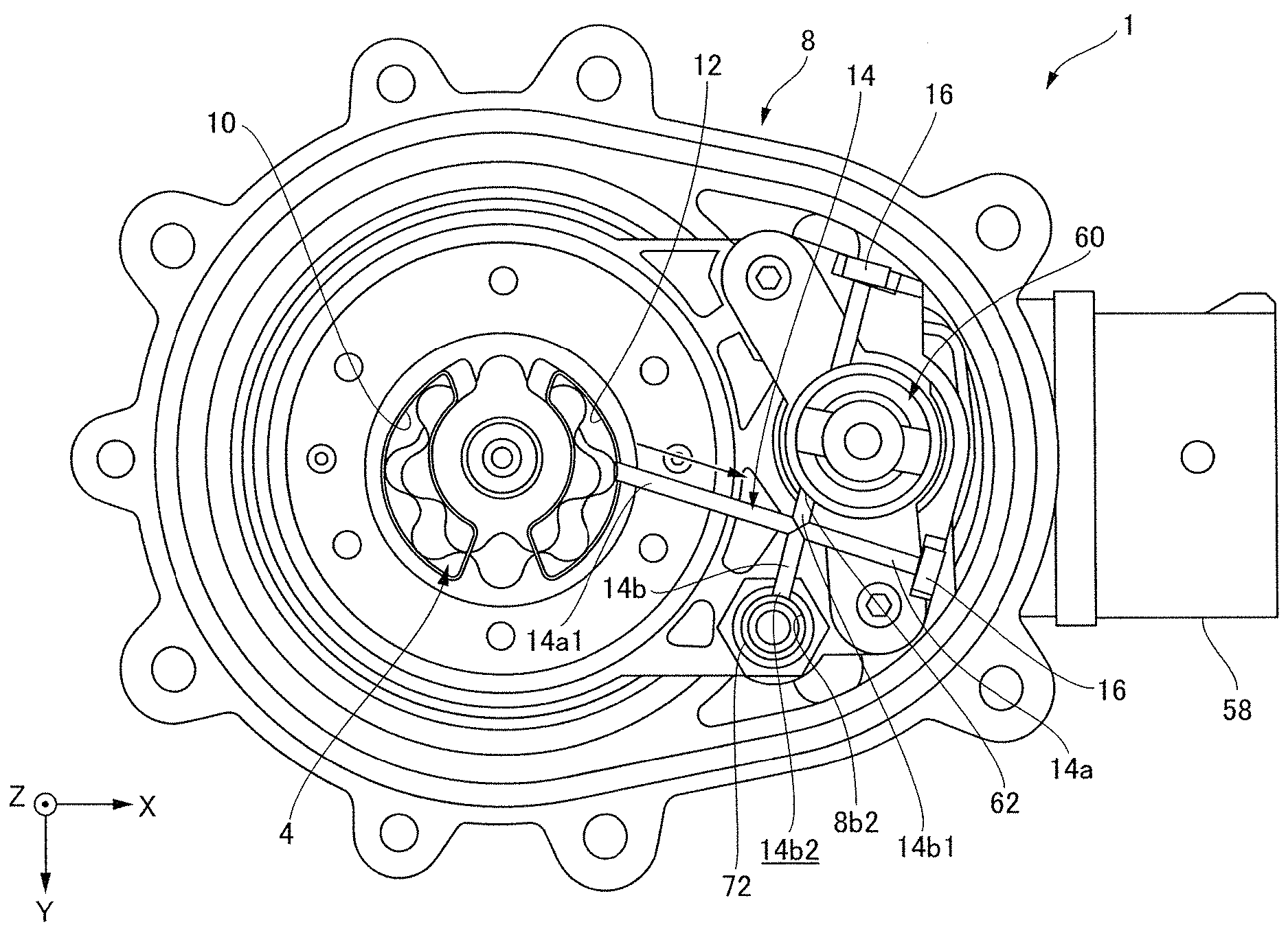
[0014] FIG. 4 illustrates a plan view of the oil pump which shows the internal structure of the pump cover.
[0015] FIG. 5 illustrates an exploded perspective view of the pump cover in which a solenoid valve and a pressure sensor are installed.
[0016] FIG. 6 illustrates an exploded perspective view of the oil pump in which the pump cover is installed at a motor section provided with a pump body.
DETAILED DESCRIPTION
[0017] Hereinafter, oil pumps according to example embodiments of the present disclosure will be described with reference to the drawings. However, the dimensions, materials, shapes, relative arrangements and the like of the component parts described in the example embodiments or shown in the drawings are not intended to limit the scope of the present disclosure to the described contents but are merely illustrative examples. For example, an expression representing a relative or unambiguous arrangement, such as "in a direction," "along a direction," "parallel," "orthogonal," "center," "concentric" or "coaxial," not only represents such an arrangement strictly, but also represents a relatively displaced state with a tolerance or an angle and a distance which can obtain the same function. For example, an expression representing that things are in the same state, such as "identical," "equal" and "homogeneous," not only represents equal states strictly, but also represents a state in which a tolerance or a difference in which the same function can be obtained is present. For example, an expression representing shapes such as a square shape and a cylindrical shape not only represents shapes such as a square shape and a cylindrical shape in a geometrically strict sense, but also represents shapes including an uneven portion, a chamfered portion, and the like in the range in which the same effect can be obtained. On the other hand, an expression "comprising," "having," "having," "including" or "having" one component is not an exclusive expression excluding the presence of other components.
[0018] Further, in the drawings, an XYZ coordinate system is shown as a three-dimensional orthogonal coordinate system as appropriate. In the XYZ coordinate system, a Z-axis direction is a direction parallel to one axial direction of a central axis J shown in FIG. 1. An X-axis direction is a direction parallel to a short side direction of an oil pump shown in FIG. 1, that is, a vertical direction in FIG. A Y-axis direction is orthogonal to both the X-axis direction and the Z-axis direction.
[0019] Further, in the following description, a positive side (+Z side) in the Z-axis direction is referred to as "front side," and a negative side (-Z side) in the Z-axis direction is referred to as "rear side." "Rear side" and "front side" are names used merely for the purpose of explanation and do not limit the actual positional relationship or direction. Also, unless otherwise indicated, a direction parallel to the central axis J (the Z-axis direction) is simply referred to as "axial direction," a radial direction about the central axis J is simply referred to as "radial direction," and a circumferential direction about the central axis J, that is, a circumference of the central axis J (in a .theta. direction), is simply referred to as "circumferential direction."
[0020] In the specification, the term "extending in the axial direction" includes not only extending strictly in the axial direction (the Z-axis direction) but also extending in a direction inclined at a range of less than 45.degree. with respect to the axial direction. Further, in the specification, the term "extending in the radial direction" includes not only extending strictly in the radial direction, that is, in a direction perpendicular to the axial direction (the Z-axis direction), but also extending in a direction inclined at a range of less than 45.degree. with respect to the radial direction.
[0021] FIG. 1 illustrates a perspective view of an oil pump according to a first example embodiment. FIG. 2 illustrates a cross-sectional view of a main part of the oil pump.
First Example Embodiment
[0022] An oil pump 1 of the example embodiment has a motor section 20 and a pump section 3 as shown in FIGS. 1 and 2. The motor section 20 has a shaft 41 disposed along a central axis J which extends in the axial direction. The pump section 3 is located on one side of the motor section 20 in the axial direction and is driven by the motor section 20 via the shaft 41 to discharge oil. That is, the motor section 20 and the pump section 3 are provided side by side in the axial direction. Hereinafter, the respective components will be described in detail.
<Motor Section 20>
[0023] As shown in FIG. 2, the motor section 20 includes a housing 21, a rotor 40, a shaft 41, a stator 50, and a bearing 55.
[0024] The motor section 20 is, for example, an inner rotor type motor, the rotor 40 is fixed to an outer circumferential surface of the shaft 41, and the stator 50 is located radially outward from the rotor 40. In addition, the bearing 55 is disposed at an end portion of the shaft 41 on the rear side (the -Z side) in the axial direction and rotatably supports the shaft 41.
(Housing 21)
[0025] The housing 21 has a thin cylindrical shape with a bottom, and includes a bottom surface portion 21a, a stator holding part 21b, a pump body holding part 21c, a side wall portion 21d, and flange portions 24 and 25. The bottom surface portion 21a forms a bottomed portion, and the stator holding part 21b, the pump body holding part 21c, and the side wall portion 21d form a cylindrical side wall surface centered on the central axis J. In the example embodiment, an inner diameter of the stator holding part 21b is larger than an inner diameter of the pump body holding part 21c. An outer surface of the stator 50, that is, an outer surface of a core back portion 51 which will be described below, is fitted to an inner surface of the stator holding part 21b. Therefore, the stator 50 is accommodated in the housing 21.
[0026] The flange portion 24 extends radially outward from an end portion of the side wall portion 21d on the front side (the +Z side). On the other hand, the flange portion 25 extends radially outward from an end portion of the stator holding part 21b on the rear side (the -Z side). The flange portion 24 and the flange portion 25 face each other and are fastened by a fastening means (not shown). Therefore, the motor section 20 and the pump section 3 are sealed and fixed in the housing 21.
[0027] For example, a zinc-aluminum-magnesium-based alloy or the like can be used as a material of the housing 21, and specifically, a hot-dip zinc-aluminum-magnesium alloy plated steel plate and a steel strip can be used. Since the housing 21 is formed of a metal and has high heat conductivity and a large surface area, a heat radiation effect is high. Further, a bearing holding part 56 for holding the bearing 55 is provided on the bottom surface portion 21a.
(Rotor 40)
[0028] The rotor 40 has a rotor core 43 and a rotor magnet 44. The rotor core 43 is fixed to the shaft 41 to surround the shaft 41 around an axis thereof (in the .theta. direction). The rotor magnet 44 is fixed to an outer surface of the rotor core 43 around an axis thereof (in the .theta. direction). The rotor core 43 and the rotor magnet 44 rotate with the shaft 41.
(Stator 50)
[0029] The stator 50 surrounds the rotor 40 around an axis thereof (in the .theta. direction) and rotates the rotor 40 around the central axis J. The stator 50 has the core back portion 51, a tooth portion 52, a coil 53, and an insulator (a bobbin) 54.
[0030] The core back portion 51 has a cylindrical shape which is concentric with the shaft 41. The tooth portion 52 extends from an inner surface of the core back portion 51 toward the shaft 41. A plurality of tooth portions 52 are provided and are disposed at equal intervals in the circumferential direction of the inner surface of the core back portion 51. The coil 53 is provided around the insulator (the bobbin) 54, and a conductive wire 53a is wound thereon. The insulator (the bobbin) 54 is installed at each of the tooth portions 52.
(Bearing 55)
[0031] The bearing 55 is disposed on the rear side (the -Z side) of the rotor 40 and the stator 50 and is held by the bearing holding part 56. The bearing 55 supports the shaft 41. A shape, structure, and the like of the bearing 55 are not particularly limited, and any known bearing can be used.
(Shaft 41)
[0032] The shaft 41 extends along the central axis J and passes through the motor section 20. The front side (the +Z side) of the shaft 41 protrudes from the motor section 20 and extends into the pump section 3. An end portion of the shaft 41 on the front side (the +Z side) is disposed in a discharge port 11 of a pump cover 8. The rear side (the -Z side) of the shaft 41 is protrudes from the motor section 20 and is supported by the bearing 55 installed in a bus bar holder 58.
<Pump Section 3>
[0033] The pump section 3 is located on one side of the motor section 20 in the axial direction, specifically, on the front side (the +Z side). The pump section 3 is driven by the motor section 20 via the shaft 41. The pump section 3 has a pump rotor 4 and a pump housing 5. The pump housing 5 has an intake port 9, the discharge port 11, and a pressure sensor 70. Furthermore, the pump housing 5 has a pump body 6, the pump cover 8 and a receiving port 12.
(Pump Body 6)
[0034] The pump body 6 is fixed into the front side (the +Z side) of the housing 21 on the front side of the motor section 20. The pump body 6 has an accommodation portion 7 which accommodates the pump rotor 4 and has a side surface and a bottom surface located on the other side of the motor section 20 in the axial direction. The accommodation portion 7 opens on the front side (the +Z side) and is recessed on the rear side (the -Z side). A shape seen in the axial direction of the accommodation portion 7 is circular.
[0035] The pump body 6 has a through hole 6a which passes therethrough along the central axis J. Both ends of the through hole 6a in the axial direction open to allow the shaft 41 to pass therethrough, an opening thereof on the front side (the +Z side) opens to the accommodation portion 7, and an opening thereof on the rear side (the -Z side) opens to the motor section 20 side. The through hole 6a serves as a bearing which rotatably supports the shaft 41.
(Pump Rotor 4)
[0036] The pump rotor 4 is installed on the shaft 41. More specifically, the pump rotor 4 is installed on the front side (the +Z side) of the shaft 41. The pump rotor 4 has an inner rotor 4a installed on the shaft 41 and an outer rotor 4b which surrounds the outside of the inner rotor 4a in the radial direction. The inner rotor 4a has an annular shape. The inner rotor 4a is a gear having teeth on an outer surface thereof in the radial direction.
[0037] The inner rotor 4a is fixed to the shaft 41. More specifically, the end portion of the shaft 41 on the front side (the +Z side) is press-fitted to the inside of the inner rotor 4a. The inner rotor 4a rotates with the shaft 41 around an axis thereof (in the .theta. direction). The outer rotor 4b has an annular shape which surrounds the outside of the inner rotor 4a in the radial direction. The outer rotor 4b is a gear which has teeth on an inner surface thereof in the radial direction.
[0038] The inner rotor 4a and the outer rotor 4b engage with each other, and the outer rotor 4b rotates as the inner rotor 4a rotates. That is, rotation of the shaft 41 causes the pump rotor 4 to rotate. In other words, the motor section 20 and the pump section 3 have the same rotation axis. Therefore, it is possible to restrain an increase in size of the electric oil pump in the axial direction. Further, the rotation of the inner rotor 4a and the outer rotor 4b changes a volume of an engagement portion between the inner rotor 4a and the outer rotor 4b. A region in which the volume decreases is a pressure region, and a region in which the volume increases is a negative pressure region. A suction port 10 is disposed on one side (the front side) of the negative pressure region of the pump rotor 4 in the axial direction. Further, the receiving port 12 is disposed in the pressure region of the pump rotor 4 on one side (the front side) in the axial direction. Here, the oil suctioned from the intake port 9 into the accommodation portion 7 is accommodated in a volume portion between the inner rotor 4a and the outer rotor 4b and is sent to the discharge port 11 side. Thereafter, the oil is discharged from the discharge port 11.
(Pump Cover 8)
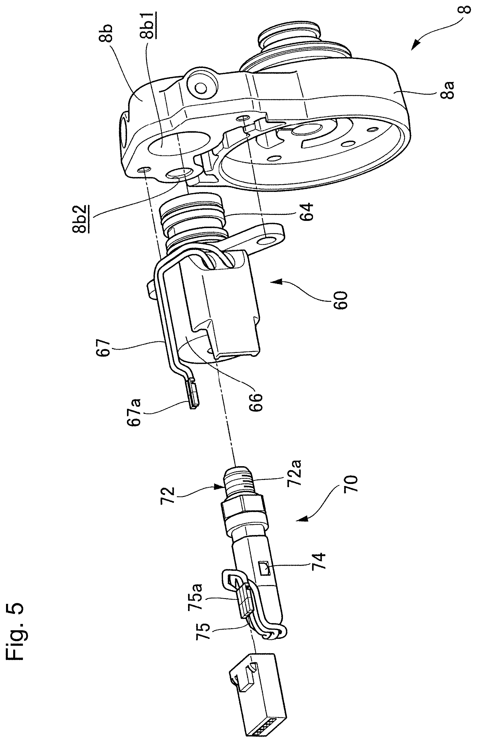
[0039] The pump cover 8 is installed on one side (the front side) of the pump body 6 in the axial direction and closes an opening portion 7a opened to one side (the front side) of the accommodation portion 7 in the axial direction. In the example embodiment shown in FIGS. 1 and 2, the pump cover 8 has a disk-shaped cover main body portion 8a which extends in the radial direction, and a protruding portion 8b which protrudes from an end portion of the cover main body portion 8a in the radial direction. The cover main body portion 8a closes the opening portion 7a on the front side of the accommodation portion 7.
(Cover Main Body Portion 8a)
[0040] The cover main body portion 8a has a first stepped portion 8a1 and a second stepped portion 8a2 which protrude on the front side (the +Z side) in the axial direction. The first stepped portion 8a1 has a cylindrical shape, is provided substantially coaxially with the central axis J and is connected to a central axis side end portion of a surface 8a3 of the cover main body portion 8a on the front side (the +Z side) in the axial direction. The cover main body portion 8a has a through hole 8a4 along the central axis J. The through hole 8a4 passes through a space between both end portions of the pump cover 8 in the axial direction. The shaft 41 passes through the through hole 8a4.
[0041] The second step portion 8a2 is provided substantially coaxially with the central axis J and has a cylindrical shape of which a diameter is smaller than that of the first stepped portion 8a1. The second stepped portion 8a2 is connected to a central axis side end portion of a surface 8a5 of the first stepped portion 8a1 on the front side (the +Z side) in the axial direction. The second stepped portion 8a2 has a large diameter hole 8a6 having a diameter larger than that of the through hole 8a4 along the central axis J, and one end of the shaft 41 in the axial direction is disposed in the large diameter hole 8a6.
[0042] The discharge port 11 has a first discharge port 11a and a second discharge port 11b. In the example embodiment, the first discharge port 11a is the large diameter hole 8a6. The second discharge port 11b is provided on the tip end side of the protruding portion 8b of the pump cover 8 which will be described below in detail. The suction port 10 and a receiving port 12 are provided in the other end of the cover main body portion 8a. The suction port 10 is provided on the side opposite to the protruding portion 8b with respect to the central axis J. The receiving port 12 is provided on the protruding portion 8b side with respect to the central axis J.
[0043] More specifically, as shown in FIGS. 2 and 3, the suction port 10 is provided at a position opposite to the negative pressure region, curved in the circumferential direction with respect to the central axis J and extends in the form of a long hole. Further, the receiving port 12 is provided at a position opposed to the pressure region, curved in the circumferential direction with respect to the central axis J and extending in the form of a long hole. Therefore, the oil suctioned from the intake port 9 can be supplied over substantially the entire negative pressure region. Also, all of the oil supplied from the pressure region can be received by the receiving port 12.
[0044] The intake port 9 communicates with the suction port 10 and opens to one end of the first stepped portion 8a1 in the axial direction. That is, the intake port 9 is provided across the cover main body portion 8a and the first stepped portion 8a1. Thus, the intake port 9 is connected to the negative pressure region of the accommodation portion 7 via the suction port 10.
[0045] The first discharge port 11a and the receiving port 12 are connected via a communication path 15. In the example embodiment shown in FIG. 2, one end of the communication path 15 opens to an inner side surface of the first discharge port 11a, and the other end thereof opens to one side (the front side) of the receiving port 12 in the axial direction. Therefore, the oil received in the receiving port 12 can flow to the first discharge port 11a through the communication path 15. A flow path 17 through which the oil flows between the receiving port 12 and the first discharge port 11a is hereinafter referred to as a first flow path 13.
[0046] A control valve 81 is connected to the first discharge port 11a via a main flow path 80. The main flow path 80 supplies the oil discharged from the first discharge port 11a to the control valve 81. The control valve 81 controls supply and discharge of the oil supplied from the main flow path 80 to, for example, an automatic transmission of a vehicle.
(Protruding Portion 8b)
[0047] As shown in FIGS. 1 and 2, the protruding portion 8b protrudes from the other radial end portion of the cover main body portion 8a in a direction perpendicular to the axial direction. A tip end of the protruding portion 8b is located radially outward from the housing 21 of the motor section 20. The protruding portion 8b has a substantially rectangular shape when seen from one side (the front side) in the axial direction. A solenoid insertion hole 8b1 (refer to FIG. 5) is provided on the tip end side of the protruding portion 8b to pass therethrough in the axial direction. The second discharge port 11b is an opening portion which opens to one side (the front side) of the solenoid insertion hole 8b1 in the axial direction. Hereinafter, the flow path 17 which communicates the second discharge port 11b with the accommodation portion 7 will be referred to as a second flow path 14.
(Second Flow Path 14)
[0048] As shown in FIGS. 2, 3 and 4, one end of the second flow path 14 is connected to the receiving port 12, and the other end thereof is connected to the second discharge port 11b via a solenoid valve 60. In the illustrated example embodiment, the second flow path 14 passes through a first through hole 14a which extends from the receiving port 12 to the tip end side of the protruding portion 8b and passes through at the tip end portion of the protruding portion 8b, and a second through hole 14b which extends from an end portion of the protruding portion 8b on one side (the negative side in the Y-axis direction) in the right and left direction toward the solenoid insertion hole 8b1, passes through the solenoid insertion hole 8b1, extends to the pressure sensor insertion hole 8b2 side while intersecting the first through hole 14a and opens to the pressure sensor insertion hole 8b2. Sealing members 16 are provided at the opening portion of the first through hole 14a on the tip end side of the protruding portion 8b and at the opening portion of the second through hole 14b on one side in the right and left direction of the protruding portion 8b to close the opening portions. In the illustrated example embodiment, the sealing members 16 are male screws.
[0049] That is, the second flow path 14 passes through a first through hole portion 14a1 of the first through hole 14a between the receiving port 12 and an intersection portion 14c at which the first through hole 14a and the second through hole 14b intersect, and a second through hole portion 14b1 of the second through hole 14b between the intersection portion 14c and the solenoid insertion hole 8b1. Although the details will be described below, the second through hole portion 14b1 is connected to a second suction port 62 of the solenoid valve 60. Further, a third discharge port 63 of the solenoid valve 60 is connected to the second discharge port 11b. Therefore, the second flow path 14 communicates the receiving port 12 with the second discharge port 11b via the second suction port 62 of the solenoid valve 60.
[0050] The second flow path 14 is provided in the pump cover 8 by, for example, a cutting operation (for example, drilling). For example, the first through hole 14a is cut from the tip end of the protruding portion 8b of the pump cover 8 to the receiving port 12 side of the pump cover 8, and the second through hole 14b is then cut from an end portion of an outer circumferential portion of the protruding portion 8b on the positive side in the Y-axis direction toward the solenoid insertion hole 8b1, the first through hole 14a and the pressure sensor insertion hole 8b2. Additionally, female threads are provided at an opening end of the first through hole 14a which opens to the outer circumferential portion of the protruding portion 8b and an opening end of the second through hole 14b which opens to an end portion of the protruding portion 8b on the positive side in the Y-axis direction, and the sealing member 16 is screwed and fixed into each of the opening ends. Thus, the second flow path 14 may be provided in the pump cover 8 by cutting. Therefore, workability of an operation for providing the second flow path 14 inside the pump cover 8 can be improved.
[0051] Thus, as shown in FIG. 2, the pump cover 8 includes the cover main body portion 8a and the protruding portion 8b. The pump cover 8 is disposed on one side (the front side) of the motor section 20 in the axial direction, and an axial region of the pump cover 8 is disposed in a region different from an axial region of the motor section 20. In the illustrated example embodiment, the axial region of the pump cover 8 is disposed in a region of the motor section 20 on one side (the front side) in the axial direction. That is, the axial region of the pump cover 8 does not overlap the axial region of the motor section 20 in the axial direction, and the axial region of the pump cover 8 is disposed at a position at which it does not face the axial region of the motor section 20.
[0052] Accordingly, as compared with a case in which the second flow path 14 is provided on the outside of the motor section 20 in the radial direction, a flow path length of the second flow path 14 can be shortened. Therefore, since the pressure sensor 70 can be disposed in the vicinity of the pump rotor 4 serving as a hydraulic pressure source, a pressure of the oil discharged from the pump rotor 4 can be detected more accurately.
(Solenoid Valve 60)
[0053] FIG. 5 illustrates an exploded perspective view of the pump cover 8 on which the solenoid valve 60 and the pressure sensor 70 are installed. As shown in FIGS. 2 and 5, the solenoid valve 60 includes a valve housing 64 which accommodates an opening and closing part 65 to be movable therein, a drive part 66 which moves the opening and closing part 65 relative to the valve housing 64, and a solenoid feed line 67 of which one end portion is connected to the drive part 66 and at the other end of which a solenoid valve side feed terminal 67a is provided. The opening and closing part 65 extends in a longitudinal direction of the valve housing 64 and is movably supported to open and close the second suction port 62. In the illustrated example embodiment, the opening and closing part 65 is a spool.
[0054] The valve housing 64 has the second suction port 62 into which the oil flowing in the second flow path 14 flows, and the third discharge port 63 that discharges the flowed oil. The second suction port 62 is opened and closed by movement of the opening and closing part 65. Thus, the flow of the oil flowing through the second flow path 14 can be blocked and allowed by opening and closing the second suction port 62. When the second suction port 62 is opened, the second suction port 62 and the third discharge port 63 are in a communication state. Therefore, when the second suction port 62 is opened, the oil flowing through the second flow path 14 is discharged from the second discharge port 11b through the second suction port 62 and the third discharge port 63. Thus, some of the oil flowing through the first flow path 13 can be allowed to flow to the second flow path 14 side by the solenoid valve 60 opening and closing the second flow path 14. Therefore, the flow rate of the oil to a supply destination of the pressurized oil supplied from the first discharge port 11a can be adjusted.
[0055] In the solenoid valve 60, when the second suction port 62 is opened by the opening and closing part 65, the flow rate of the oil discharged from the second discharge port 11b may be larger than the flow rate of the oil discharged from the first discharge port. In this case, for example, an opening area of the second discharge port 11b is made larger than an opening area of the first discharge port 11a. In this way, as an amount of oil flowing through the second discharge port 11b is larger than that of the first discharge port 11a, a range of flow rate adjustment of the oil discharged from the first discharge port 11a can be expanded.
[0056] The drive part 66 is, for example, an electromagnetic clutch. The drive part 66 moves the opening and closing part 65 by a magnetic force generated from the drive part 66 and opens the second suction port 62 when power is supplied to the drive part 66 and then returns the opening and closing part 65 to its original position by biasing of a spring (not shown) and closes the second suction port 62 when the power supply to the drive part 66 is cut off. Therefore, a position of the opening and closing part 65 can be adjusted to control the opening and closing of the second suction port 62 by controlling the power supply to the drive part 66.
[0057] The third discharge port 63 opens to one end portion of the valve housing 64 in the longitudinal direction (one end portion thereof in the axial direction). On the other hand, the second discharge port 11b provided in the protruding portion 8b is an opening of the solenoid insertion hole 8b1 on one side (the front side) in the axial direction. The valve housing 64 of the solenoid valve 60 is inserted and fixed into the solenoid insertion hole 40b1. The valve housing 64 is supported in a state in which one end portion thereof in the axial direction is located on substantially the same plane as the second discharge port 11b. Thus, the second discharge port 11b and the third discharge port 63 are disposed on substantially the same plane, and the second discharge port 11b and the third discharge port 63 are connected to each other to be in a communication state.
[0058] The second discharge port 11b is connected to an oil pan T capable of storing the oil. In the illustrated example embodiment, the second discharge port 11b communicates with the oil pan T via a tank flow path 83.
(Pressure Sensor 70)
[0059] As shown in FIG. 1, the pressure sensor 70 is fixed to the protruding portion 8b and extends to the motor section 20 side. In the illustrated example embodiment, the pressure sensor 70 is disposed at the outside of the housing 21 of the motor section 20 and is fixed to an end portion of the protruding portion 8b on the minus side in the Y axis direction. As shown in FIG. 5, the pressure sensor 70 has a sensor part 72 which detects a hydraulic pressure of the oil, and an electric line holding part 74 which holds a sensor electrical line 75 electrically connected to the sensor part 72. The sensor part 72 has a cylindrical shape, and a male screw part 72a is provided on an outer circumferential surface of the sensor part 72. A female screw portion to which the male screw part 72a can be screwed is provided in the pressure sensor insertion hole 8b2. Therefore, the pressure sensor 70 is fixed to the pump cover 8 through the pressure sensor insertion hole 8b2.
[0060] As shown in FIG. 4, an opening portion 14b2 of the second through hole 14b at an end portion thereof on the plus side in the Y axis direction opens to a portion of the pressure sensor insertion hole 8b2 into which the sensor part 72 is inserted. The opening portion 14b2 communicates with the sensor part 72. Therefore, the hydraulic pressure of the oil in each of the first flow path 13 and the second flow path 14 can be detected through the first through hole 14a and the second through hole 14b. That is, when the second flow path 14 is closed by the solenoid valve 60, the pressure sensor 70 can detect the hydraulic pressure of the oil in the first flow path 13, and when the second flow path 14 is opened by the solenoid valve 60, the pressure sensor 70 can detect the hydraulic pressure of the oil in the second flow path 14.
[0061] The pressure sensor 70 converts, for example, a change in electrical resistance due to a piezoresistive effect into an electrical signal. The electrical signal is transmitted to a sensor side terminal 75a provided in the sensor electrical line 75 via the sensor electrical line 75, as shown in FIG. 5. The electrical signal transmitted to the sensor side terminal 75a is transmitted to, for example, an engine controller. The engine controller controls an operation of an automatic transmission, an engine, and the like of a vehicle and controls an operation of the drive part 66 (refer to FIG. 2) of the solenoid valve 60 on the basis of the electrical signal from the pressure sensor 70 to control the opening and closing of the second suction port 62.
[0062] As described above, the sensor part 72 of the pressure sensor 70 is fixed into the pressure sensor insertion hole 8b2 of the protruding portion 8b. Further, the protruding portion 8b extends in a direction orthogonal to the axial direction. Thus, as shown in FIG. 2, the sensor part 72 of the pressure sensor 70 is disposed between the first discharge port 11a or the second discharge port 11b and the accommodation portion 7 when seen in the direction orthogonal to the axial direction. In the example embodiment, the sensor part 72 is disposed between the first discharge port 11a and the accommodation portion 7 and between the second discharge port 11b and the accommodation portion 7. Accordingly, an end portion of the pressure sensor 70 on one side (the front side) in the axial direction does not protrude from one end portion of the oil pump 1 the axial direction. Therefore, an increase in a length of the oil pump 1 in the axial direction can be restrained. The sensor part 72 may be disposed between any one of the first discharge port 11a and the second discharge port 11b and the accommodation portion 7.
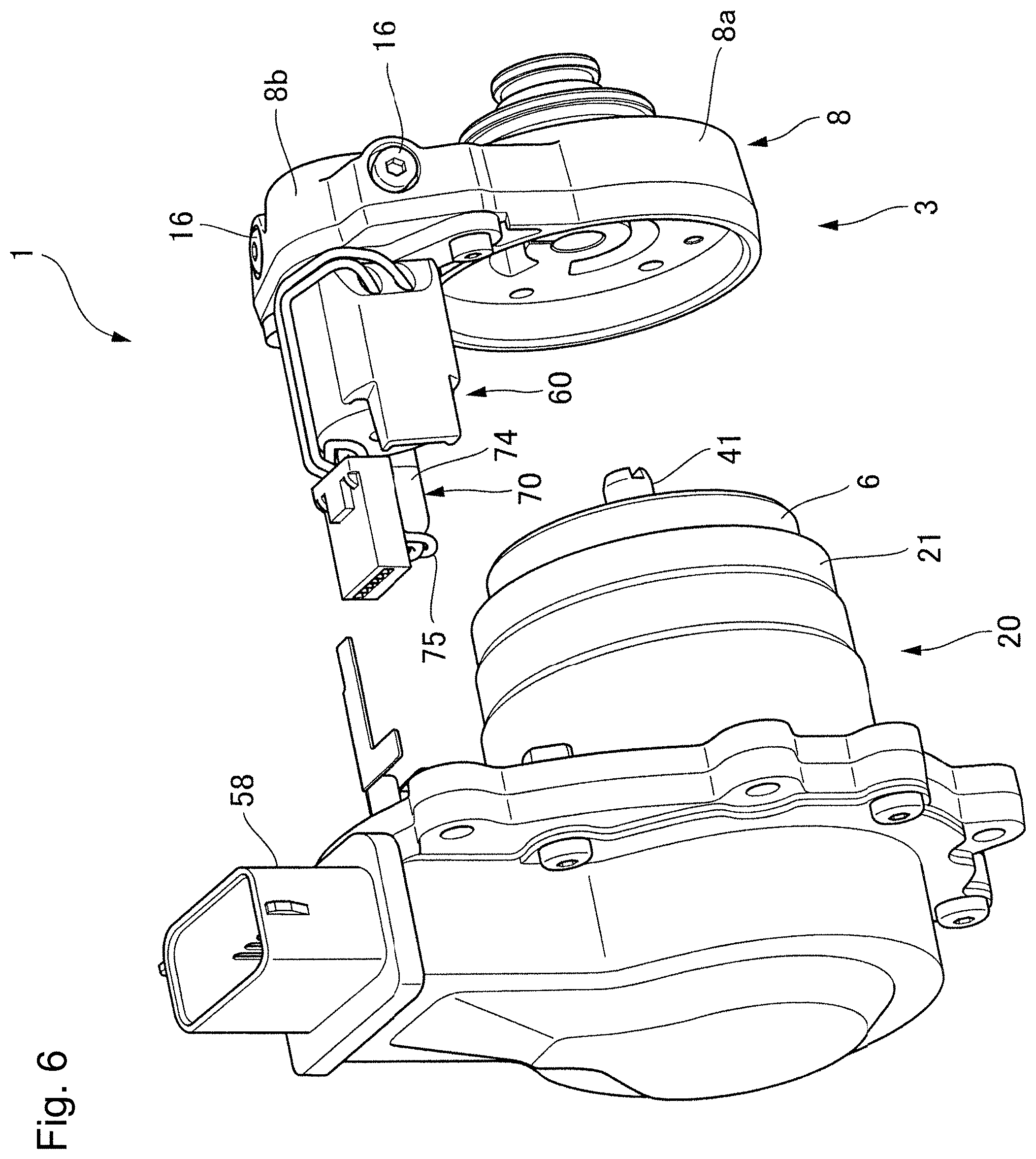
[0063] FIG. 6 illustrates an exploded perspective view of the oil pump 1 in which the pump cover 8 is installed in the motor section 20 provided with the pump body 6.
[0064] As shown in FIGS. 1 and 6, the electric line holding part 74 of the pressure sensor 70 and the solenoid valve 60 are disposed adjacent to each other and extend in the axial direction of the motor section 20. In the illustrated example embodiment, the solenoid valve 60 is disposed at the central portion of the protruding portion 8b in the right and left direction (the Y-axis direction) with respect to a protruding direction thereof, and the electric line holding part 74 is disposed on one side of the protruding portion 8b in the right and left direction. Further, the electric line holding part 74 and the solenoid valve 60 are disposed in a direction orthogonal to a surface of the protruding portion 8b on the rear side (the -Z side) in the axial direction. Therefore, since the pressure sensor 70 and the solenoid valve 60 are disposed in the axial direction of the motor section 20, the oil pump 1 can be miniaturized as compared with a case in which the pressure sensor 70 and the solenoid valve 60 are disposed in directions different from each other.
<Operation and Effect of Oil Pump 1>
[0065] Next, an operation and an effect of the oil pump 1 will be described. As shown in FIG. 2, when the motor section 20 of the oil pump 1 is driven, the oil suctioned from the intake port 9 of the pump section 3 moves in the accommodation portion 7 of the pump section 3 and is discharged from the first discharge port 11a via the receiving port 12 and the communication path 15. The oil discharged from the first discharge port 11a is supplied to the control valve 81 via the main flow path 80.
[0066] Here, since the pump section 3 according to the example embodiment is a volume change type trochoid pump, oil vibration occurs in the oil discharged from the oil pump 1 due to a pressure fluctuation of the oil pump 1. Due to the oil vibration, for example, when a clutch of an automatic transmission is brought into a half clutch state, the operation may be unstable. In order to eliminate this instability, it is conceivable to increase a frequency of the oil vibration by increasing RPM of the oil pump 1 from, for example, 400 to 1200. However, simply increasing the RPM to increase the frequency of the oil vibration may cause resonance and thus may not prevent judder in the half clutch state.
[0067] Therefore, in the oil pump 1 according to the example embodiment, the pump cover 8 of the pump housing 5 has a solenoid valve 60 connected to the second flow path 14 which communicates the discharge port 11 (the second discharge port 11b) with the accommodation portion 7, such that some of the oil supplied from the first discharge port 11a to the supply destination (for example, the clutch destination) of the pressurized oil can flow to the solenoid valve 60 side. Therefore, for example, in the case in which the supply destination of the pressurized oil is the clutch destination, even when the RPM of the oil pump 1 is increased from, for example, 400 to 1200, it is possible to restrain an increase in the flow rate of the oil supplied to the clutch. Therefore, the frequency of the oil vibration can be increased and shifted to a frequency for avoiding resonance. Accordingly, the pressure in the half clutch state can be maintained while the judder in the half clutch state is prevented.
[0068] Further, in the oil pump 1 according to the example embodiment, the pressure sensor 70 capable of detecting the hydraulic pressure of the oil in the second flow path 14 is disposed between the discharge port 11 (the first discharge port 11a and the second discharge port 11b) and the accommodation portion 7. Thus, an end portion of the pressure sensor 70 on one side (the front side) in the axial direction does not protrude from one end portion of the oil pump 1 the axial direction. Therefore, the increase in the length of the oil pump 1 in the axial direction can be restrained. Further, the oil pump 1 according to the example embodiment can be disposed in the vicinity of the pump rotor 4 which is a generation source of the hydraulic pressure, as compared with a case in which the pressure sensor 70 is provided in the control valve 81. Accordingly, since the hydraulic pressure of the oil discharged from the pump rotor 4 can be accurately detected, the respective hydraulic pressures in the first flow path 13 and the second flow path 14 can be accurately detected.
[0069] Also, the solenoid valve 60 has the second suction port through which the pressurized oil discharged from the pump section 3 is suctioned, and the third discharge port 63 through which the pressurized oil is discharged toward the oil pan T capable of storing the oil. Furthermore, the pump housing 5 includes the pump body 6 having the accommodation portion 7 which accommodates the pump rotor 4 and has the side surface and the bottom surface located on the other side of the motor section in the axial direction, the pump cover 8 which closes the opening portion 7a that opens from one side (the front side) of the pump body 6 in the axial direction to one side (the front side) of the accommodation portion 7 in the axial direction, and the receiving port 12 which receives the oil discharged from the accommodation portion 7. The pump cover 8 has the first flow path 13 which communicates the receiving port 12 with the first discharge port 11a, and the second flow path 14 which communicates the receiving port 12 with the second discharge port 11b. The second flow path 14 communicates the receiving port 12 with the second discharge port 11b via the second suction port 62 of the solenoid valve 60. The second discharge port 11b of the pump cover 8 is connected to the third discharge port 63 of the solenoid valve 60.
[0070] Therefore, the second flow path 14 which connects the pump section 3 with the solenoid valve 60 can be shortened. Therefore, an increase in a size of the oil pump 1 can be restrained. Moreover, as compared with a case in which the second flow path 14 is provided as a separate member, a number of parts can be reduced, and an increase in cost of the oil pump 1 can be restrained.
[0071] Also, the pump cover 8 has the protruding portion 8b which protrudes radially outward from an outer periphery of the motor section 20, and the protruding portion 8b has the second flow path 14 and the second discharge port 11b. Therefore, the second flow path 14 and the second discharge port 11b can be provided adjacent to each other. Thus, the increase in the size of the oil pump 1 can be restrained. Moreover, as compared with the case in which the second flow path 14 is provided as a separate member, a number of parts can be reduced, and the increase in the cost of the oil pump 1 can be restrained.
[0072] Further, the pressure sensor 70 and the solenoid valve 60 are fixed to the protruding portion 8b and extend toward the motor section 20 side. Therefore, the pressure sensor 70 and the solenoid valve 60 can be disposed along the motor section 20, and the increase in the size of the oil pump 1 can be restrained.
[0073] Further, the pressure sensor 70 is disposed such that the longitudinal direction thereof is parallel to the axial direction. Therefore, the miniaturization of the pump device can be promoted as compared with a case in which the longitudinal direction of the pressure sensor 70 is disposed in a direction intersecting the axial direction.
[0074] Although the preferred example embodiment of the present disclosure have been described above, the present disclosure is not limited to the example embodiment, and various modifications and changes are possible within the scope of the present disclosure.
[0075] While example embodiments of the present disclosure have been described above, it is to be understood that variations and modifications will be apparent to those skilled in the art without departing from the scope and spirit of the present disclosure. The scope of the present disclosure, therefore, is to be determined solely by the following claims.
* * * * *
D00000
D00001
D00002
D00003
D00004
D00005
D00006
XML
uspto.report is an independent third-party trademark research tool that is not affiliated, endorsed, or sponsored by the United States Patent and Trademark Office (USPTO) or any other governmental organization. The information provided by uspto.report is based on publicly available data at the time of writing and is intended for informational purposes only.
While we strive to provide accurate and up-to-date information, we do not guarantee the accuracy, completeness, reliability, or suitability of the information displayed on this site. The use of this site is at your own risk. Any reliance you place on such information is therefore strictly at your own risk.
All official trademark data, including owner information, should be verified by visiting the official USPTO website at www.uspto.gov. This site is not intended to replace professional legal advice and should not be used as a substitute for consulting with a legal professional who is knowledgeable about trademark law.