Surgical stapler with integrated bladder
Gleiman , et al. June 1, 2
U.S. patent number 11,020,578 [Application Number 15/092,720] was granted by the patent office on 2021-06-01 for surgical stapler with integrated bladder. This patent grant is currently assigned to Covidien LP. The grantee listed for this patent is Covidien LP. Invention is credited to Anthony Ceniccola, Matthew Chowaniec, Seth Gleiman, Gerald Hodgkinson, David Racenet, Jeffrey Schmitt, Joshua Snow.


| United States Patent | 11,020,578 |
| Gleiman , et al. | June 1, 2021 |
Surgical stapler with integrated bladder
Abstract
An end effector includes first and second members that each have a tissue contacting surface and are moveable relative to one another. The first and second members are configured to clamp tissue therebetween when in an approximated configuration. The tissue contacting surface of the first member defines a first groove. The end effector also includes a bladder that is defined within the first groove and is configured to receive and retain fluid.
| Inventors: | Gleiman; Seth (Guilford, CT), Ceniccola; Anthony (Hamden, CT), Chowaniec; Matthew (Madison, CT), Racenet; David (Killingworth, CT), Hodgkinson; Gerald (Guilford, CT), Snow; Joshua (Clinton, CT), Schmitt; Jeffrey (Trumbull, CT) | ||||||||||
|---|---|---|---|---|---|---|---|---|---|---|---|
| Applicant: |
|
||||||||||
| Assignee: | Covidien LP (Mansfield,
MA) |
||||||||||
| Family ID: | 1000005587615 | ||||||||||
| Appl. No.: | 15/092,720 | ||||||||||
| Filed: | April 7, 2016 |
Prior Publication Data
| Document Identifier | Publication Date | |
|---|---|---|
| US 20160296227 A1 | Oct 13, 2016 | |
Related U.S. Patent Documents
| Application Number | Filing Date | Patent Number | Issue Date | ||
|---|---|---|---|---|---|
| 62148827 | Apr 17, 2015 | ||||
| 62145930 | Apr 10, 2015 | ||||
| Current U.S. Class: | 1/1 |
| Current CPC Class: | A61M 37/00 (20130101); A61B 17/1155 (20130101); A61B 17/07207 (20130101); A61B 17/00491 (20130101); A61B 2017/00884 (20130101); A61B 2017/00893 (20130101); A61B 2017/07214 (20130101); A61B 2017/07271 (20130101) |
| Current International Class: | A61M 37/00 (20060101); A61B 17/115 (20060101); A61B 17/00 (20060101); A61B 17/072 (20060101) |
References Cited [Referenced By]
U.S. Patent Documents
| 3054406 | September 1962 | Usher |
| 3079606 | March 1963 | Bobrov et al. |
| 3124136 | March 1964 | Usher |
| 3364200 | January 1968 | Ashton et al. |
| 3490675 | January 1970 | Green et al. |
| 3499591 | March 1970 | Green |
| 3939068 | February 1976 | Wendt et al. |
| 3948666 | April 1976 | Kitanishi et al. |
| 4064062 | December 1977 | Yurko |
| 4166800 | September 1979 | Fong |
| 4282236 | August 1981 | Broom |
| 4347847 | September 1982 | Usher |
| 4354628 | October 1982 | Green |
| 4416698 | November 1983 | McCorsley, III |
| 4429695 | February 1984 | Green |
| 4452245 | June 1984 | Usher |
| 4605730 | August 1986 | Shalaby et al. |
| 4626253 | December 1986 | Broadnax, Jr. |
| 4655221 | April 1987 | Devereux |
| 4834090 | May 1989 | Moore |
| 4838884 | June 1989 | Dumican et al. |
| 4927640 | May 1990 | Dahlinder et al. |
| 4930674 | June 1990 | Barak |
| 5002551 | March 1991 | Linsky et al. |
| 5014899 | May 1991 | Presty et al. |
| 5040715 | August 1991 | Green et al. |
| 5057334 | October 1991 | Vail |
| 5065929 | November 1991 | Schulze et al. |
| 5162430 | November 1992 | Rhee et al. |
| 5205459 | April 1993 | Brinkerhoff et al. |
| 5263629 | November 1993 | Trumbull et al. |
| 5307976 | May 1994 | Olson et al. |
| 5312023 | May 1994 | Green et al. |
| 5314471 | May 1994 | Brauker et al. |
| 5318221 | June 1994 | Green et al. |
| 5324775 | June 1994 | Rhee et al. |
| 5326013 | July 1994 | Green et al. |
| 5332142 | July 1994 | Robinson et al. |
| 5344454 | September 1994 | Clarke et al. |
| 5392979 | February 1995 | Green et al. |
| 5397324 | March 1995 | Carroll et al. |
| 5410016 | April 1995 | Hubbell et al. |
| 5425745 | June 1995 | Green et al. |
| 5441193 | August 1995 | Gravener |
| 5441507 | August 1995 | Wilk |
| 5443198 | August 1995 | Viola et al. |
| 5468253 | November 1995 | Bezwada et al. |
| 5484913 | January 1996 | Stilwell et al. |
| 5503638 | April 1996 | Cooper et al. |
| 5514379 | May 1996 | Weissleder et al. |
| 5542594 | August 1996 | McKean et al. |
| 5543441 | August 1996 | Rhee et al. |
| 5549628 | August 1996 | Cooper et al. |
| 5550187 | August 1996 | Rhee et al. |
| 5575803 | November 1996 | Cooper et al. |
| 5653756 | August 1997 | Clarke et al. |
| 5683809 | November 1997 | Freeman et al. |
| 5690675 | November 1997 | Sawyer et al. |
| 5702409 | December 1997 | Raybum et al. |
| 5752965 | May 1998 | Francis et al. |
| 5752974 | May 1998 | Rhee et al. |
| 5762256 | June 1998 | Mastri et al. |
| 5766188 | June 1998 | Igaki |
| 5769892 | June 1998 | Kingwell |
| 5782396 | July 1998 | Mastri et al. |
| 5799857 | September 1998 | Robertson et al. |
| 5810855 | September 1998 | Rayburn et al. |
| 5814057 | September 1998 | Oi et al. |
| 5819350 | October 1998 | Wang |
| 5833695 | November 1998 | Yoon |
| 5843096 | December 1998 | Igaki et al. |
| 5874500 | February 1999 | Rhee et al. |
| 5895412 | April 1999 | Tucker |
| 5895415 | April 1999 | Chow et al. |
| 5902312 | May 1999 | Frater et al. |
| 5908427 | June 1999 | McKean et al. |
| 5915616 | June 1999 | Viola et al. |
| 5931847 | August 1999 | Bittner et al. |
| 5964774 | October 1999 | McKean et al. |
| 5997895 | December 1999 | Narotam et al. |
| 6019791 | February 2000 | Wood |
| 6030392 | February 2000 | Dakov |
| 6032849 | March 2000 | Mastri et al. |
| 6045560 | April 2000 | McKean et al. |
| 6063097 | May 2000 | Oi et al. |
| 6080169 | June 2000 | Turtel |
| 6093557 | July 2000 | Pui et al. |
| 6099551 | August 2000 | Gabbay |
| 6149667 | November 2000 | Hovland et al. |
| 6152943 | November 2000 | Sawhney |
| 6155265 | December 2000 | Hammerslag |
| 6156677 | December 2000 | Brown Reed et al. |
| 6165201 | December 2000 | Sawhney et al. |
| 6179862 | January 2001 | Sawhney |
| 6210439 | April 2001 | Firmin et al. |
| 6214020 | April 2001 | Mulhauser et al. |
| 6241139 | June 2001 | Milliman et al. |
| 6258107 | July 2001 | Balazs et al. |
| 6267772 | July 2001 | Mulhauser et al. |
| 6273897 | August 2001 | Dalessandro et al. |
| 6280453 | August 2001 | Kugel et al. |
| 6299631 | October 2001 | Shalaby |
| 6309569 | October 2001 | Farrar et al. |
| 6312457 | November 2001 | DiMatteo et al. |
| 6312474 | November 2001 | Francis et al. |
| 6325810 | December 2001 | Hamilton et al. |
| 6399362 | June 2002 | Pui et al. |
| 6436030 | August 2002 | Rehil |
| 6454780 | September 2002 | Wallace |
| 6461368 | October 2002 | Fogarty et al. |
| 6500777 | December 2002 | Wiseman et al. |
| 6503257 | January 2003 | Grant et al. |
| 6514283 | February 2003 | DiMatteo et al. |
| 6514534 | February 2003 | Sawhney |
| 6517566 | February 2003 | Hovland et al. |
| 6551356 | April 2003 | Rousseau |
| 6566406 | May 2003 | Pathak et al. |
| 6590095 | July 2003 | Schleicher et al. |
| 6592597 | July 2003 | Grant et al. |
| 6605294 | August 2003 | Sawhney |
| 6627749 | September 2003 | Kumar |
| 6638285 | October 2003 | Gabbay |
| 6652594 | November 2003 | Francis et al. |
| 6656193 | December 2003 | Grant et al. |
| 6656200 | December 2003 | Li et al. |
| 6669735 | December 2003 | Pelissier |
| 6673093 | January 2004 | Sawhney |
| 6677258 | January 2004 | Carroll et al. |
| 6685714 | February 2004 | Rousseau |
| 6702828 | March 2004 | Whayne |
| 6703047 | March 2004 | Sawhney et al. |
| 6704210 | March 2004 | Myers |
| 6723114 | April 2004 | Shalaby |
| 6726706 | April 2004 | Dominguez |
| 6736823 | May 2004 | Darois et al. |
| 6736854 | May 2004 | Vadurro et al. |
| 6746458 | June 2004 | Cloud |
| 6746869 | June 2004 | Pui et al. |
| 6764720 | July 2004 | Pui et al. |
| 6773458 | August 2004 | Brauker et al. |
| 6818018 | November 2004 | Sawhney |
| 6896684 | May 2005 | Monassevitch et al. |
| 6927315 | August 2005 | Heinecke et al. |
| 6939358 | September 2005 | Palacios et al. |
| 6946196 | September 2005 | Foss |
| 6953139 | October 2005 | Milliman et al. |
| 6959851 | November 2005 | Heinrich |
| 7009034 | March 2006 | Pathak et al. |
| 7060087 | June 2006 | DiMatteo et al. |
| 7087065 | August 2006 | Ulmsten et al. |
| 7108701 | September 2006 | Evens et al. |
| 7128253 | October 2006 | Mastri et al. |
| 7128748 | October 2006 | Mooradian et al. |
| 7134438 | November 2006 | Makower et al. |
| 7141055 | November 2006 | Abrams et al. |
| 7147138 | December 2006 | Shelton, IV |
| 7160299 | January 2007 | Baily |
| 7232449 | June 2007 | Sharkawy et al. |
| 7241300 | July 2007 | Sharkawy et al. |
| 7247338 | July 2007 | Pui et al. |
| 7279322 | October 2007 | Pui et al. |
| 7307031 | December 2007 | Carroll et al. |
| 7311720 | December 2007 | Mueller et al. |
| 7347850 | March 2008 | Sawhney |
| 7377928 | May 2008 | Zubik et al. |
| 7434717 | October 2008 | Shelton, IV et al. |
| 7438209 | October 2008 | Hess |
| 7455682 | November 2008 | Viola |
| 7498063 | March 2009 | Pui et al. |
| 7547312 | June 2009 | Bauman et al. |
| 7559937 | July 2009 | de la Torre et al. |
| 7571845 | August 2009 | Viola |
| 7592418 | September 2009 | Pathak et al. |
| 7594921 | September 2009 | Browning |
| 7595392 | September 2009 | Kumar et al. |
| 7604151 | October 2009 | Hess et al. |
| 7611494 | November 2009 | Campbell et al. |
| 7635073 | December 2009 | Heinrich |
| 7649089 | January 2010 | Kumar et al. |
| 7662801 | February 2010 | Kumar et al. |
| 7665646 | February 2010 | Prommersberger |
| 7666198 | February 2010 | Suyker et al. |
| 7669747 | March 2010 | Weisenburgh, II et al. |
| 7673783 | March 2010 | Morgan |
| 7717313 | May 2010 | Criscuolo et al. |
| 7722642 | May 2010 | Williamson, IV et al. |
| 7744627 | June 2010 | Orban, III et al. |
| 7776060 | August 2010 | Mooradian et al. |
| 7793813 | September 2010 | Bettuchi |
| 7799026 | September 2010 | Schechter et al. |
| 7823592 | November 2010 | Bettuchi et al. |
| 7824420 | November 2010 | Eldridge et al. |
| 7845533 | December 2010 | Marczyk et al. |
| 7845536 | December 2010 | Viola |
| 7846149 | December 2010 | Jankowski |
| 7892247 | February 2011 | Conston et al. |
| 7909224 | March 2011 | Prommersberger |
| 7909837 | March 2011 | Crews et al. |
| 7938307 | May 2011 | Bettuchi |
| 7942890 | May 2011 | D'Agostino et al. |
| 7950561 | May 2011 | Aranyi |
| 7951166 | May 2011 | Orban, III et al. |
| 7951248 | May 2011 | Fallis et al. |
| 7967179 | June 2011 | Olson et al. |
| 7988027 | August 2011 | Olson et al. |
| 8011550 | September 2011 | Aranyi et al. |
| 8011555 | September 2011 | Tarinelli et al. |
| 8016177 | September 2011 | Bettuchi et al. |
| 8016178 | September 2011 | Olson et al. |
| 8028883 | October 2011 | Stopek |
| 8033483 | October 2011 | Fortier et al. |
| 8038045 | October 2011 | Bettuchi et al. |
| 8062330 | November 2011 | Prommersberger et al. |
| 8062673 | November 2011 | Figuly et al. |
| 8083119 | December 2011 | Prommersberger |
| 8123766 | February 2012 | Bauman et al. |
| 8123767 | February 2012 | Bauman et al. |
| 8146791 | April 2012 | Bettuchi et al. |
| 8152777 | April 2012 | Campbell et al. |
| 8157149 | April 2012 | Olson et al. |
| 8157151 | April 2012 | Ingmanson et al. |
| 8167895 | May 2012 | D'Agostino et al. |
| 8178746 | May 2012 | Hildeberg et al. |
| 8192460 | June 2012 | Orban, III et al. |
| 8201720 | June 2012 | Hessler |
| 8210414 | July 2012 | Bettuchi et al. |
| 8210453 | July 2012 | Hull et al. |
| 8225799 | July 2012 | Bettuchi |
| 8225981 | July 2012 | Criscuolo et al. |
| 8231043 | July 2012 | Tarinelli et al. |
| 8235273 | August 2012 | Olson et al. |
| 8245901 | August 2012 | Stopek |
| 8252339 | August 2012 | Figuly et al. |
| 8252921 | August 2012 | Vignon et al. |
| 8256654 | September 2012 | Bettuchi et al. |
| 8257391 | September 2012 | Orban, III et al. |
| 8276800 | October 2012 | Bettuchi |
| 8286849 | October 2012 | Bettuchi |
| 8292154 | October 2012 | Marczyk |
| 8308042 | November 2012 | Aranyi |
| 8308045 | November 2012 | Bettuchi et al. |
| 8308046 | November 2012 | Prommersberger |
| 8312885 | November 2012 | Bettuchi et al. |
| 8313014 | November 2012 | Bettuchi |
| 8348126 | January 2013 | Olson et al. |
| 8348130 | January 2013 | Shah et al. |
| 8365972 | February 2013 | Aranyi et al. |
| 8367089 | February 2013 | Wan et al. |
| 8371491 | February 2013 | Huitema et al. |
| 8371492 | February 2013 | Aranyi et al. |
| 8371493 | February 2013 | Aranyi et al. |
| 8393514 | March 2013 | Shelton, IV et al. |
| 8408440 | April 2013 | Olson et al. |
| 8408480 | April 2013 | Hull et al. |
| 8413869 | April 2013 | Heinrich |
| 8413871 | April 2013 | Racenet et al. |
| 8418909 | April 2013 | Kostrzewski |
| 8424742 | April 2013 | Bettuchi |
| 8453652 | June 2013 | Stopek |
| 8453904 | June 2013 | Eskaros et al. |
| 8453909 | June 2013 | Olson et al. |
| 8453910 | June 2013 | Bettuchi et al. |
| 8464925 | June 2013 | Hull et al. |
| 8470360 | June 2013 | McKay |
| 8474677 | July 2013 | Woodard, Jr. et al. |
| 8479968 | July 2013 | Hodgkinson et al. |
| 8485414 | July 2013 | Criscuolo et al. |
| 8496683 | July 2013 | Prommersberger et al. |
| 8511533 | August 2013 | Viola et al. |
| 8512402 | August 2013 | Marczyk et al. |
| 8518440 | August 2013 | Blaskovich et al. |
| 8529600 | September 2013 | Woodard, Jr. et al. |
| 8540131 | September 2013 | Swayze |
| 8551138 | October 2013 | Orban, III et al. |
| 8556918 | October 2013 | Bauman et al. |
| 8561873 | October 2013 | Ingmanson et al. |
| 8584920 | November 2013 | Hodgkinson |
| 8590762 | November 2013 | Hess et al. |
| 8616430 | December 2013 | (Prommersberger) Stopek et al. |
| 8617132 | December 2013 | Golzarian et al. |
| 8631989 | January 2014 | Aranyi et al. |
| 8646674 | February 2014 | Schulte et al. |
| 8668129 | March 2014 | Olson |
| 8678263 | March 2014 | Viola |
| 8684250 | April 2014 | Bettuchi et al. |
| 8721703 | May 2014 | Fowler |
| 8757466 | June 2014 | Olson et al. |
| 8789737 | July 2014 | Hodgkinson et al. |
| 8820606 | September 2014 | Hodgkinson |
| 8870050 | October 2014 | Hodgkinson |
| 8920444 | December 2014 | Hiles et al. |
| 8939344 | January 2015 | Olson et al. |
| 8967448 | March 2015 | Carter et al. |
| 9005243 | April 2015 | Stopek et al. |
| 9010606 | April 2015 | Aranyi et al. |
| 9010608 | April 2015 | Casasanta, Jr. et al. |
| 9010609 | April 2015 | Carter et al. |
| 9010610 | April 2015 | Hodgkinson |
| 9010612 | April 2015 | Stevenson et al. |
| 9016543 | April 2015 | (Prommersberger) Stopek et al. |
| 9016544 | April 2015 | Hodgkinson et al. |
| 9044227 | June 2015 | Shelton, IV et al. |
| 9055944 | June 2015 | Hodgkinson et al. |
| 9084602 | July 2015 | Gleiman |
| 9107665 | August 2015 | Hodgkinson et al. |
| 9107667 | August 2015 | Hodgkinson |
| 9113871 | August 2015 | Milliman et al. |
| 9113873 | August 2015 | Marczyk et al. |
| 9113885 | August 2015 | Hodgkinson et al. |
| 9113893 | August 2015 | Sorrentino et al. |
| 9161753 | October 2015 | Prior |
| 9161757 | October 2015 | Bettuchi |
| 9375259 | June 2016 | Payne |
| 9895147 | February 2018 | Shelton, IV |
| 10130359 | November 2018 | Hess |
| 2002/0028243 | March 2002 | Masters |
| 2002/0086990 | July 2002 | Kumar et al. |
| 2002/0091397 | July 2002 | Chen |
| 2003/0065345 | April 2003 | Neadock |
| 2003/0078209 | April 2003 | Schmidt |
| 2003/0083676 | May 2003 | Wallace |
| 2003/0120284 | June 2003 | Palacios et al. |
| 2003/0181927 | September 2003 | Wallace |
| 2003/0183671 | October 2003 | Mooradian et al. |
| 2003/0208231 | November 2003 | Williamson et al. |
| 2004/0093029 | May 2004 | Zubik et al. |
| 2004/0107006 | June 2004 | Francis et al. |
| 2004/0254590 | December 2004 | Hoffman et al. |
| 2004/0260315 | December 2004 | Dell et al. |
| 2005/0002981 | January 2005 | Lahtinen et al. |
| 2005/0021085 | January 2005 | Abrams et al. |
| 2005/0059996 | March 2005 | Bauman et al. |
| 2005/0059997 | March 2005 | Bauman et al. |
| 2005/0070929 | March 2005 | Dalessandro et al. |
| 2005/0118435 | June 2005 | DeLucia et al. |
| 2005/0131225 | June 2005 | Kumar et al. |
| 2005/0143756 | June 2005 | Jankowski |
| 2005/0145671 | July 2005 | Viola |
| 2005/0149073 | July 2005 | Arani et al. |
| 2005/0154093 | July 2005 | Kwon et al. |
| 2006/0004407 | January 2006 | Hiles et al. |
| 2006/0008505 | January 2006 | Brandon |
| 2006/0093672 | May 2006 | Kumar et al. |
| 2006/0111738 | May 2006 | Wenchell |
| 2006/0121266 | June 2006 | Fandel et al. |
| 2006/0135992 | June 2006 | Bettuchi et al. |
| 2006/0173470 | August 2006 | Oray et al. |
| 2006/0178683 | August 2006 | Shimoji et al. |
| 2006/0271104 | November 2006 | Viola et al. |
| 2007/0026031 | February 2007 | Bauman et al. |
| 2007/0034669 | February 2007 | de la Torre et al. |
| 2007/0049953 | March 2007 | Shimoji et al. |
| 2007/0054880 | March 2007 | Saferstein et al. |
| 2007/0073340 | March 2007 | Shelton et al. |
| 2007/0114262 | May 2007 | Mastri et al. |
| 2007/0123839 | May 2007 | Rousseau et al. |
| 2007/0179528 | August 2007 | Soltz et al. |
| 2007/0203509 | August 2007 | Bettuchi |
| 2007/0203510 | August 2007 | Bettuchi |
| 2007/0213522 | September 2007 | Harris et al. |
| 2007/0243227 | October 2007 | Gertner |
| 2007/0246505 | October 2007 | Pace-Floridia et al. |
| 2008/0029570 | February 2008 | Shelton et al. |
| 2008/0082126 | April 2008 | Murray et al. |
| 2008/0110959 | May 2008 | Orban |
| 2008/0125812 | May 2008 | Zubik et al. |
| 2008/0140115 | June 2008 | Stopek |
| 2008/0161831 | July 2008 | Bauman et al. |
| 2008/0161832 | July 2008 | Bauman et al. |
| 2008/0164440 | July 2008 | Maase et al. |
| 2008/0169327 | July 2008 | Shelton et al. |
| 2008/0169328 | July 2008 | Shelton |
| 2008/0169329 | July 2008 | Shelton et al. |
| 2008/0169330 | July 2008 | Shelton et al. |
| 2008/0169331 | July 2008 | Shelton et al. |
| 2008/0169332 | July 2008 | Shelton et al. |
| 2008/0169333 | July 2008 | Shelton et al. |
| 2008/0200949 | August 2008 | Hiles et al. |
| 2008/0220047 | September 2008 | Sawhney et al. |
| 2008/0230583 | September 2008 | Heinrich |
| 2008/0290134 | November 2008 | Bettuchi et al. |
| 2008/0308608 | December 2008 | Prommersberger |
| 2008/0314960 | December 2008 | Marczyk et al. |
| 2009/0001121 | January 2009 | Hess et al. |
| 2009/0001122 | January 2009 | Prommersberger et al. |
| 2009/0001123 | January 2009 | Morgan et al. |
| 2009/0001124 | January 2009 | Hess et al. |
| 2009/0001125 | January 2009 | Hess et al. |
| 2009/0001126 | January 2009 | Hess et al. |
| 2009/0001128 | January 2009 | Weisenburgh, II et al. |
| 2009/0001130 | January 2009 | Hess et al. |
| 2009/0005808 | January 2009 | Hess et al. |
| 2009/0030452 | January 2009 | Bauman et al. |
| 2009/0043334 | February 2009 | Bauman et al. |
| 2009/0076510 | March 2009 | Bell et al. |
| 2009/0076528 | March 2009 | Sgro |
| 2009/0078739 | March 2009 | Viola |
| 2009/0095791 | April 2009 | Eskaros et al. |
| 2009/0095792 | April 2009 | Bettuchi |
| 2009/0120994 | May 2009 | Murray |
| 2009/0134200 | May 2009 | Tarinelli et al. |
| 2009/0206125 | August 2009 | Huitema et al. |
| 2009/0206126 | August 2009 | Huitema et al. |
| 2009/0206139 | August 2009 | Hall et al. |
| 2009/0206141 | August 2009 | Huitema et al. |
| 2009/0206142 | August 2009 | Huitema et al. |
| 2009/0206143 | August 2009 | Huitema et al. |
| 2009/0218384 | September 2009 | Aranyi |
| 2009/0277944 | November 2009 | Dalessandro et al. |
| 2009/0277947 | November 2009 | Viola |
| 2009/0287230 | November 2009 | D'Agostino et al. |
| 2010/0012704 | January 2010 | Tarinelli Racenet et al. |
| 2010/0016888 | January 2010 | Calabrese et al. |
| 2010/0065606 | March 2010 | Stopek |
| 2010/0065607 | March 2010 | Orban, III et al. |
| 2010/0072254 | March 2010 | Aranyi et al. |
| 2010/0087840 | April 2010 | Ebersole et al. |
| 2010/0147921 | June 2010 | Olson |
| 2010/0147922 | June 2010 | Olson |
| 2010/0147923 | June 2010 | D'Agostino et al. |
| 2010/0203151 | August 2010 | Hiraoka |
| 2010/0204641 | August 2010 | Wenchell |
| 2010/0243707 | September 2010 | Olson et al. |
| 2010/0243708 | September 2010 | Aranyi et al. |
| 2010/0243711 | September 2010 | Olson et al. |
| 2010/0249805 | September 2010 | Olson et al. |
| 2010/0264195 | October 2010 | Bettuchi |
| 2010/0282815 | November 2010 | Bettuchi et al. |
| 2010/0331880 | December 2010 | Stopek |
| 2011/0024476 | February 2011 | Bettuchi et al. |
| 2011/0024481 | February 2011 | Bettuchi et al. |
| 2011/0036894 | February 2011 | Bettuchi |
| 2011/0042442 | February 2011 | Viola et al. |
| 2011/0046650 | February 2011 | Bettuchi |
| 2011/0057016 | March 2011 | Bettuchi |
| 2011/0087279 | April 2011 | Shah et al. |
| 2011/0089375 | April 2011 | Chan et al. |
| 2011/0215132 | September 2011 | Aranyi et al. |
| 2011/0278346 | November 2011 | Hull |
| 2011/0293690 | December 2011 | Griffin et al. |
| 2012/0018487 | January 2012 | Bettuchi et al. |
| 2012/0074199 | March 2012 | Olson et al. |
| 2012/0080336 | April 2012 | Shelton, IV et al. |
| 2012/0083723 | April 2012 | Vitaris et al. |
| 2012/0150221 | June 2012 | Viola |
| 2012/0187179 | July 2012 | Gleiman |
| 2012/0197272 | August 2012 | Oray et al. |
| 2012/0241492 | September 2012 | Shelton, IV |
| 2012/0241499 | September 2012 | Baxter, III et al. |
| 2012/0273547 | November 2012 | Hodgkinson et al. |
| 2013/0032626 | February 2013 | Smith et al. |
| 2013/0037596 | February 2013 | Bear et al. |
| 2013/0062391 | March 2013 | Boudreaux |
| 2013/0105548 | May 2013 | Hodgkinson et al. |
| 2013/0105553 | May 2013 | (Tarinelli) Racenet et al. |
| 2013/0112732 | May 2013 | Aranyi et al. |
| 2013/0112733 | May 2013 | Aranyi et al. |
| 2013/0146641 | June 2013 | Shelton, IV et al. |
| 2013/0153635 | June 2013 | Hodgkinson |
| 2013/0153636 | June 2013 | Shelton, IV et al. |
| 2013/0153638 | June 2013 | Carter et al. |
| 2013/0153639 | June 2013 | Hodgkinson et al. |
| 2013/0153640 | June 2013 | Hodgkinson |
| 2013/0153641 | June 2013 | Shelton, IV et al. |
| 2013/0161374 | June 2013 | Swayze |
| 2013/0193186 | August 2013 | (Tarinelli) Racenet et al. |
| 2013/0193192 | August 2013 | Casasanta, Jr. et al. |
| 2013/0209659 | August 2013 | Racenet et al. |
| 2013/0240600 | September 2013 | Bettuchi |
| 2013/0240601 | September 2013 | Bettuchi et al. |
| 2013/0240602 | September 2013 | Stopek |
| 2013/0256380 | October 2013 | Schmid et al. |
| 2013/0277411 | October 2013 | Hodgkinson et al. |
| 2013/0306707 | November 2013 | Viola et al. |
| 2013/0310873 | November 2013 | Stopek (nee Prommersberger) et al. |
| 2013/0327807 | December 2013 | Olson et al. |
| 2014/0012317 | January 2014 | Orban et al. |
| 2014/0021242 | January 2014 | Hodgkinson et al. |
| 2014/0027490 | January 2014 | Marczyk et al. |
| 2014/0034704 | February 2014 | Ingmanson et al. |
| 2014/0048580 | February 2014 | Merchant et al. |
| 2014/0061280 | March 2014 | Ingmanson et al. |
| 2014/0097224 | April 2014 | Prior |
| 2014/0131418 | May 2014 | Kostrzewski |
| 2014/0131419 | May 2014 | Bettuchi |
| 2014/0138423 | May 2014 | Whitfield et al. |
| 2014/0151431 | June 2014 | Hodgkinson et al. |
| 2014/0155916 | June 2014 | Hodgkinson et al. |
| 2014/0158742 | June 2014 | Stopek (nee Prommersberger) et al. |
| 2014/0166721 | June 2014 | Stevenson et al. |
| 2014/0197224 | July 2014 | Penna |
| 2014/0203061 | July 2014 | Hodgkinson |
| 2014/0217147 | August 2014 | Milliman |
| 2014/0217148 | August 2014 | Penna |
| 2014/0239046 | August 2014 | Milliman |
| 2014/0239047 | August 2014 | Hodgkinson et al. |
| 2014/0252062 | September 2014 | Mozdzierz |
| 2015/0001276 | January 2015 | Hodgkinson et al. |
| 2015/0041347 | February 2015 | Hodgkinson |
| 2015/0097018 | April 2015 | Hodgkinson |
| 2015/0115014 | April 2015 | Matonick |
| 2015/0115015 | April 2015 | Prescott et al. |
| 2015/0122872 | May 2015 | Olson et al. |
| 2015/0164503 | June 2015 | Stevenson et al. |
| 2015/0164506 | June 2015 | Carter et al. |
| 2015/0164507 | June 2015 | Carter et al. |
| 2015/0196297 | July 2015 | (Prommersberger) Stopek et al. |
| 2015/0209033 | July 2015 | Hodgkinson |
| 2015/0209045 | July 2015 | Hodgkinson et al. |
| 2015/0209048 | July 2015 | Carter et al. |
| 2016/0206864 | July 2016 | Matonick |
| 2016/0206865 | July 2016 | Matonick |
| 19924311 | Nov 2000 | DE | |||
| 0 327 022 | Aug 1989 | EP | |||
| 0 594 148 | Apr 1994 | EP | |||
| H06327684 | Nov 1994 | JP | |||
| 2000-166933 | Jun 2000 | JP | |||
| 2002-202213 | Jul 2002 | JP | |||
| 2007-124166 | May 2007 | JP | |||
| 90/05489 | May 1990 | WO | |||
| 95/16221 | Jun 1995 | WO | |||
| 2006044799 | Apr 2006 | WO | |||
| 2010075298 | Jul 2010 | WO | |||
Other References
|
International Search Report dated Jul. 25, 2016, issued in PCT/US2016/026334. cited by applicant . Extended European Search Report dated Jan. 15, 2019 issued in corresponding EP Appln. No. 16777239.1. cited by applicant . Australian Office Action issued in Application No. 2016246716 dated Nov. 21, 2019. cited by applicant . Australian Office Action issued in Application No. 2016246716, dated Apr. 14, 2020. cited by applicant . Extended European Search Report issued in EP Application No. EP16777239.1, dated Jan. 15, 2019. cited by applicant. |
Primary Examiner: Kinsaul; Anna K
Assistant Examiner: Leeds; Daniel Jeremy
Attorney, Agent or Firm: Carter DeLuca & Farrell LLP
Parent Case Text
CROSS-REFERENCE TO RELATED APPLICATIONS
This application claims the benefit of and priority to U.S. Provisional Patent Application Ser. No. 62/148,827 filed Apr. 17, 2015, this application also claims the benefit of and priority to U.S. Provisional Patent Application Ser. No. 62/145,930 filed Apr. 10, 2015, the entire disclosure of which is incorporated by reference herein.
Claims
What is claimed:
1. An end effector comprising: first and second members each having a tissue contacting surface, the first and second members movable relative to one another and configured to clamp tissue therebetween in an approximated configuration, the tissue contacting surface of the first member defining a first groove; and a bladder configured to receive and retain fluid, the bladder including a first film disposed along a surface of the first groove of the first member and a second film disposed on the tissue contacting surface of the first member such that sidewalls of the first groove of the first member form sidewalls of the bladder, whereby the fluid received in the bladder is exposed to the sidewalls of the first groove of the first member; wherein in an unfilled state the second film is positioned below the tissue contacting surface of the first member, and in the filled state the second film is coplanar with the tissue contacting surface of the first member.
2. The end effector according to claim 1, wherein the bladder is configured to receive fluid when the first and second members are in the approximated configuration.
3. The end effector according to claim 1, further comprising an injection port in fluid communication with the bladder.
4. The end effector according to claim 3, wherein the injection port is located on one of the first or second members and is configured to receive fluid from an injection device while the first and second members are in the approximated configuration.
5. The end effector according to claim 1, wherein the first member includes a fastener configured to pierce the bladder as the fastener is ejected from the first member.
6. The end effector according to claim 5, wherein the bladder is configured to dispense fluid onto tissue adjacent with the tissue contacting surface of the first member when the fastener pierces the bladder.
7. The end effector according to claim 1, wherein the tissue contacting surface of the second member defines a second groove.
8. The end effector according to claim 7, further comprising a second bladder including a third film disposed along an inner surface of the second groove and a fourth film disposed on the tissue contacting surface of the second member.
9. The end effector according to claim 1, wherein the end effector is an annular end effector, the first member is a shell assembly, and the second member is an anvil assembly.
10. The end effector according to claim 1, wherein the end effector is a linear end effector, the first member is a lower jaw, and the second member is an upper jaw.
11. A method of joining tissue comprising: approximating first and second members of an end effector to clamp tissue to be joined between the first and second members; injecting fluid into a bladder defined in one of the first or second members before or after the first and second members are clamped on tissue, the bladder defined between a first film disposed in a groove of one of the first or second members and a second film on a tissue contacting surface of the same one of the first or second members such that sidewalls of the groove of the one of the first or second members form sidewalls of the bladder, whereby a fluid received in the bladder is exposed to the sidewalls of the groove of the one of the first or second members; wherein in an unfilled state the second film is positioned below the tissue contacting surface of the first member, and in a filled state the second film is coplanar with the tissue contacting surface of the first member; and ejecting a fastener from the first member such that the fastener pierces the bladder to release fluid from the bladder.
12. The method according to claim 11, wherein ejecting the fastener from the first member includes the fastener piercing the bladder before the fastener passes through the tissue to be joined and coating the fastener with fluid disposed within the bladder.
13. The method according to claim 11, wherein ejecting the fastener from the first member includes the fastener piercing the bladder after the fastener passes through the tissue to be joined such that the bladder secretes fluid on tissue adjacent a tissue contacting surface of the second member.
14. The method according to claim 11, wherein injecting fluid into a bladder includes injecting fluid that includes at least one of a therapeutic drug, a biocompatible adhesive, or a biocompatible sealant.
15. The method according to claim 11, wherein injecting fluid into a bladder includes injecting a first fluid into a bladder defined by the first member and injecting a second fluid into a bladder defined by the second member.
16. The method according to claim 15, wherein the second fluid is different from the first fluid.
17. The end effector according to claim 1, wherein the first member includes a fastener configured to pierce the first and second films as the fastener is ejected from the first member.
18. The end effector according to claim 17, wherein the fastener pierces the first film prior to piercing the second film.
19. The method according to claim 11, wherein ejecting the fastener from the first member includes the fastener piercing the first film prior to piercing the second film.
Description
BACKGROUND
1. Technical Field
The present disclosure relates to surgical instruments and, more specifically, to surgical instruments with integrated bladders.
2. Discussion of Related Art
Throughout the years the medical field has utilized various techniques in an effort to join or bond body tissue together. Surgical staplers have been developed for joining adjacent tissue, for providing hemostasis of adjacent tissue, and for providing hemostasis in conjunction with cutting of adjacent tissue. Such surgical staplers include both linear and annular type configurations. The intended function of staples is to hold the edges of a wound or tissue against one another during the healing process so as to reduce discomfort, pain, scarring and the time required for healing.
Linear or annular surgical stapling devices are employed by surgeons to sequentially or simultaneously apply one or more rows of surgical fasteners, e.g., staples or two-part fasteners, to body tissue for the purpose of joining segments of body tissue together and/or for the creation of anastomoses. Linear surgical stapling devices generally include a pair of jaws between which body tissue to be joined is placed. When the surgical stapling device is actuated and/or "fired", firing bars move longitudinally and contact staple drive members in one of the jaws, and surgical staples are pushed through the body tissue and into/against an anvil in the opposite jaw thereby crimping the staples closed. A knife blade may be provided to cut between the rows/lines of staples.
Annular surgical stapling devices generally include an annular staple cartridge assembly including a plurality of annular rows of staples, typically two rows of staples, an anvil assembly operatively associated with the annular cartridge assembly, and an annular blade disposed internal of the rows of staples.
In addition to the use of surgical staples, biological tissue adhesives have been developed for joining tissue. Generally, biological adhesives bond separated tissues together. Such adhesives may be used instead of suturing and stapling, for example, in surgical procedures, for the repair of tissue or the creation of anastomoses.
In addition to the use of biological adhesives, following the formation of the anastomosis, a separate instrument or device may be used to apply biological sealants to the outer surface of the anastomosis, typically in a separate step. The biological sealants are intended to reduce and/or stop the incidence of leakage from the anastomosis.
The application of adhesives and/or sealants offers many advantages to the patient and the surgeon alike, such as, for example, the possible reduction in the number of staples used, immediate sealing of the tissue being treated, a strengthening of the anastomosis, minimizing foreign body reaction and scarring, and a reduction in the occurrence of bleeding from the blood vessels, leakage through the tissue joint, and stricture.
There remains room for improvement in the delivery of fluids, such as adhesives and/or sealants, from surgical stapling instruments.
SUMMARY
Surgical staplers in accordance with this disclosure include end effectors having integrated bladders which dispense fluid (e.g., therapeutic drug, sealant, adhesive, or medicant) when punctured by a fastener during the joining of tissue by the surgical stapler. The bladder may be prefilled with fluid or fluid may be injected into the bladder prior to or during a surgical procedure.
In an aspect of the present disclosure, an end effector includes first and second members that each have a tissue contacting surface and are moveable relative to one another. The first and second members are configured to clamp tissue therebetween when in an approximated configuration. The tissue contacting surface of the first member defines a first groove. The end effector also includes a bladder that is defined within the first groove and is configured to receive and retain fluid.
In aspects, the bladder is configured to receive a fluid when the first and second members are in the approximated position. The bladder may be defined by an inner surface of the first groove and a first film disposed on the tissue contacting surface of the first member.
In some aspects, the end effector includes an injection port that is in fluid communication with the bladder. The injection port may be located on one of the first or second members and is configured to receive fluid from an injection device while the first and second members are in the approximated configuration.
In certain aspects, the first member includes a fastener that is configured to pierce the bladder as the fastener is ejected from the first member. The bladder may be configured to dispense a fluid onto tissue adjacent or proximate to the tissue contacting surface of the first member when the fastener pierces the bladders.
In particular aspects, the tissue contacting surface of the second member defines a second groove. The end effector may include a second bladder defined by an inner surface of the second groove and a second film disposed on the tissue contacting surface of the second member.
In aspects, the end effector is an annular end effector with the first member being a shell assembly and the second member being an anvil assembly. Alternatively, the end effector is a linear end effector with the first member being a lower jaw and the second member being an upper jaw.
In another aspect of the present disclosure, a method of joining tissue includes approximating first and second members of an end effector to clamp tissue to be joined between the first and second members, injecting fluid into a bladder defined in one of the first or second members while the first and second members are clamped on tissue, and ejecting a fastener from the first member such that the fastener pierces the bladder to release fluid from the bladder.
In aspects, ejecting the fastener from the first member includes the fastener piercing the bladder before the fastener passes through the tissue to be joined and coating the fastener with fluid disposed within the bladder. Ejecting the fastener from the first member may include the fastener piercing the bladder after the fastener passes through the tissue to be joined such that the bladder secretes fluid on tissue adjacent a tissue contacting surface of the second member.
In some aspects, injecting fluid into a bladder includes injecting fluid that includes at least one of a therapeutic drug, a biocompatible adhesive, or a biocompatible sealant. Injecting fluid into a bladder may include injecting a first fluid into a bladder that is defined by the first member and injecting a second fluid into a bladder that is defined by the second member. The second fluid may be different from the first fluid.
Further, to the extent consistent, any of the aspects described herein may be used in conjunction with any or all of the other aspects described herein.
BRIEF DESCRIPTION OF THE DRAWINGS
Various aspects of the present disclosure are described hereinbelow with reference to the drawings, which are incorporated in and constitute a part of this specification, wherein:
FIG. 1 is a perspective view of a surgical instrument with a manually actuated handle assembly and a linear stapling end effector in accordance with an exemplary embodiment of the present disclosure;
FIG. 2 is an enlarged view of the indicated area of detail of FIG. 1 with an injection device inserted into an injection port of the end effector;
FIG. 3 is a cross-sectional view taken along the section line 3-3 of FIG. 2;
FIG. 4 is a perspective view of the end effector of FIG. 2 with jaws of the end effector approximated on tissue;
FIG. 5 is a cross-sectional view taken along the second line 5-5 of FIG. 4;
FIG. 6 is a cross-sectional view of the end effector of FIG. 5 with fasteners ejected from the lower jaw to form staples;
FIG. 7 is a perspective view of a surgical instrument with a powered handle and a annular stapling end effector in accordance with another exemplary embodiment of the present disclosure;
FIG. 8 is an enlarged view of the indicated area of detail of FIG. 7 with an injection device inserted into an injection port of the end effector;
FIG. 9 is a cross-sectional view taken along the section line 9-9 of FIG. 8; and
FIG. 10 is a cross-sectional view of the end effector of FIG. 9 with the anvil assembly actuated over tissue and fasteners ejected from the shell assembly towards the anvil assembly.
DETAILED DESCRIPTION
Embodiments of the present disclosure are now described in detail with reference to the drawings in which like reference numerals designate identical or corresponding elements in each of the several views. As used herein, the term "clinician" refers to a doctor, a nurse, or any other care provider and may include support personnel. Throughout this description, the term "proximal" refers to the portion of the device or component thereof that is closest to the clinician and the term "distal" refers to the portion of the device or component thereof that is farthest from the clinician.
This disclosure is generally related to end effectors for surgical staplers including integrated bladders which disperse a fluid (e.g., therapeutic drug, sealant, adhesive, or medicant) when punctured by a fastener to assist in the joining of tissue with the surgical stapler. The bladder may be prefilled with the fluid during manufacture of the instrument or the fluid may be injected into the integrated bladder prior to or during a surgical procedure. The end effector may have an integrated bladder on each side of the tissue with the same or different fluid being dispensed from each integrated bladder. The end effector may be supplied as a part of a loading unit (disposable or reusable) or may be supplied as part of surgical instrument. The end effector may be linear or annular in configuration. In addition, the surgical stapler may be manually actuated, may be actuated by an electromechanical handle, or may be actuated by a pneumatic handle. For example, the pneumatic handle can be a handle powered by a gas cylinder.
Referring now to FIG. 1, a surgical instrument 10 having a manually actuated handle assembly 20 including a linear stapling end effector 50 is provided in accordance with an exemplary embodiment of the present disclosure. The surgical instrument 10 includes the manually actuated handle assembly 20, an elongate portion 30, a loading unit 40, and an end effector 50. The elongate portion 30 extends from the handle assembly 20 and supports the loading unit 40. The loading unit 40 is releasably coupled to the distal end of the elongate portion 30. The end effector 50 is supported at a distal end of the loading unit 40 and includes first and second jaws 52, 56 that are moveable relative to one another. The handle assembly 20 includes a moveable handle 22 that is configured to actuate the end effector 50 to approximate the first and second jaws 52, 56 of the end effector 50 relative to one another and to fire or eject a plurality of fasteners (e.g., staples) through tissue positioned between the first and second jaws 52, 56. For a detailed description of a suitable manually actuated handle assembly and stapling instrument reference may be made to U.S. Pat. No. 8,789,737 ("the '737 Patent"), the entire contents of which is incorporated herein by reference.
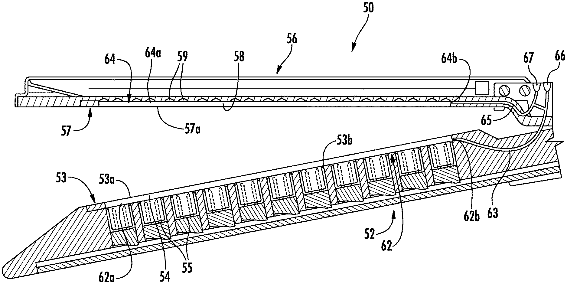
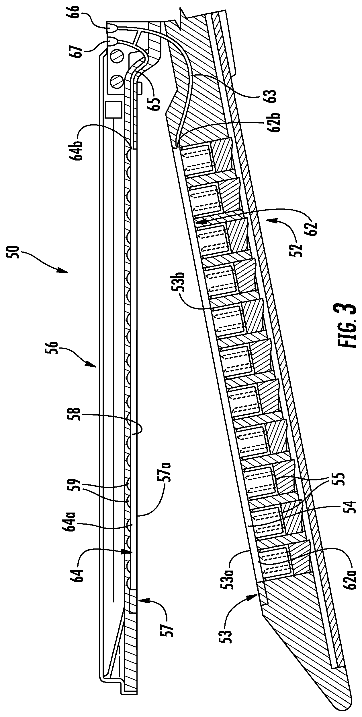
With reference to FIGS. 2 and 3, the first or lower jaw or member 52 of the end effector 50 includes a tissue contacting surface 53 that defines longitudinal grooves 54. Each of the grooves 54 includes an inner surface (in embodiments a pair of sidewalls and a bottom surface) and is positioned over a line of fasteners 55. The lower jaw 52 includes an integrated bladder 62 disposed within one or more of the grooves 54. The integrated bladder 62 is formed from an upper film 53a disposed along the tissue contacting surface 53 of the lower jaw 52 and a lower film 53b that is disposed over a bottom surface of the groove 54 such that sidewalls of the groove 54 form sidewalls of the integrated bladder 62. The upper film 53a may be disposed over the entire tissue contacting surface 53 of the lower jaw 52 and secured to the tissue contacting surface 53 between each of the grooves 54. The end effector 50 defines an injection port 66 and includes a delivery tube 63 that extends from the injection port 66, through the lower jaw 52, and to the integrated bladder 62 such that the injection port 66 is in fluid communication with the integrated bladder 62. The integrated bladder 62 may include fingers 62a with each finger 62a extending through a respective groove 54 and a plenum 62b in fluid communication with each finger 62a. The plenum 62b is in fluid communication with the injection port 66 through the delivery tube 63. Alternatively, the integrated bladder 62 may be formed from individual fingers 62a with the delivery tube 63 in fluid communication with each of the individual fingers 62a. The injection port 66 may include an auto-sealing septum to prevent injected fluid from exiting through the injection port 66.
It is also contemplated, that the integrated bladder 62 may be formed from individual fingers 62a with each finger 62a in fluid communication with the injection port 62 through an individual delivery tube 63 such that each individual delivery tube 63 is separately accessible through the injection port 66 to deliver a different fluid to each individual finger 62a. In such an embodiment, the individual fingers 62a may be paired with one or more delivery tubes 63 such that the inner fingers 62a of the integrated bladder 62 (adjacent a knife slot (not explicitly shown)) may be filled with a first fluid and the outer fingers 62a of the integrated bladder 62 (away from a knife slot (not explicitly shown)) may be filed with a second fluid that is different from the first fluid.
Further, it is contemplated that the second or upper jaw or member 56 may define longitudinal grooves 58 in a tissue contacting surface 57 of the upper jaw 56. Each of the grooves 58 is positioned over a line of staple pockets 59 or retainers (not shown). The upper jaw 56 includes an integrated bladder 64 that is disposed within each of the grooves 58 and a delivery tube 65 in fluid communication with the integrated bladder 64. The integrated bladder 64 is formed from a lower film 57a that is disposed along the tissue contacting surface 57 of the upper jaw 56 such that the staple pockets 59 and sidewalls defining the grooves 58 form the integrated bladder 64. The lower film 57a may be disposed over the entire tissue contacting surface of the upper jaw 56 and secured to the tissue contacting surface 57 between each of the grooves 58. The injection port 66 and the delivery tube 65 are also in fluid communication in a manner similar to the integrated bladder 62 and delivery tube 63 of the lower jaw 52. Similarly, the integrated bladder 64 may include fingers 64a with each finger 64a extending through a respective groove 58 and a plenum 64b in fluid communication with each finger 64a. The plenum 64b is in fluid communication with the injection port 66 through the delivery tube 65. Alternatively, the integrated bladder 64 may be formed from individual fingers 64a with the delivery tube 65 in fluid communication with each of the individual fingers 64a. In addition, the end effector 50 may define a second injection port 67 adjacent the injection port 66 which is in fluid communication with the integrated bladder 64. In such embodiments, the integrated bladder 64 of the upper jaw 56 is in fluid communication with the second injection port 67 and the integrated bladder 62 of the lower jaw 52 is in fluid communication with the injection port 66 such that each of the bladders 62, 64 may be individually and separately filled as detailed below. As shown, both injection ports 66, 67 are positioned on the upper jaw 56; however, it is contemplated that one or both of the injection ports 66, 67 may be positioned on the lower jaw 52.
Referring now to FIGS. 2-5, the integrated bladder 62 has an initial or unfilled configuration (FIGS. 2 and 3) and a filled configuration (FIGS. 4 and 5). In the unfilled configuration, the integrated bladder 62 is collapsed such that an upper surface of the integrated bladder 62 is positioned below the tissue contacting surface 53 of the lower jaw 52. In the filled configuration, fluid which is injected through the injection port 66 fills or expands the integrated bladder 62 such that the upper surface of the integrated bladder 62 is coplanar with the tissue contacting surface 53 of the lower jaw 52. In addition, as the integrated bladder 62 is filled through the injection port 66, the integrated bladder 62 may expand to fill any cavities within the grooves 54. It is contemplated that the integrated bladder 62 may include semi-rigid walls such that in the unfilled configuration the upper surface of the integrated bladder 62 is coplanar with the tissue contacting surface 53 of the lower jaw 52.
With particular reference to FIG. 2, an injection device or needle 90 may be inserted into the injection port 66 to inject a fluid into the integrated bladder 62. The fluid may include a therapeutic drug, a biocompatible sealant, a biocompatible adhesive, or a combination thereof. The material can be a bioactive material such as a drug, an immunosuppressant, steroid, entihistimine, etc. Anti-adhesives, antimicrobials, anesthetics, growth factors, or other materials are contemplated.
As the fluid is injected into the integrated bladder 62, the integrated bladder 62 transitions to the filled configuration as detailed above. As the integrated bladder 62 reaches the filled configuration, the pressure of the fluid within the needle 90 may exceed a threshold pressure to indicate that the integrated bladder 62 is in the filled configuration. Additionally or alternatively, as the integrated bladder 62 reaches the filled configuration, the fluid may flow out of the injection port 66 to provide an indication that the integrated bladder 62 is in the filled configuration. It will be appreciated that the fluid may be injected into the integrated bladder 62 before or after the upper and lower jaws 52, 56 are approximated over tissue. To fill the integrated bladder 62 after the upper and lower jaws 52, 56 are approximated over tissue, the fluid may be injected through injection port 68 or 69 (FIG. 1) which may be disposed outside of the body cavity of a patient and connected to bladders 62, 64 via a delivery tube (not explicitly shown).
As detailed above, the unfilled and filled configurations were detailed with respect to the integrated bladder 62 of the lower jaw 52. It will be appreciated that the integrated bladder 64 of the upper jaw 56 has unfilled and filled configurations substantially similar to the integrated bladder 64. As such, the unfilled and filled configurations of the integrated bladder 64 will not be discussed in detail for reasons of brevity.
With reference to FIG. 6, as the fasteners 55 are ejected from the lower jaw 52 towards the upper jaw 56, the fasteners 55 pierce the integrated bladder 62 of the lower jaw 52 such that the fasteners 53 are coated with the fluid disposed within the integrated bladder 62. The coated fasteners 55 then pass through tissue T positioned between the upper and lower jaws 52, 56. After the fasteners 55 pass through the tissue T, the fasteners 55 pierce the integrated bladder 64 of the upper jaw 56 before engaging staple pockets 59 or retainers (not shown) to secure the tissue T together.
When the integrated bladders 62, 64 are pierced, the fluid from the integrated bladders 62, 64 may coat the fasteners 55 and/or the tissue T between the upper and lower jaws 52, 56. The fluid may also flow into openings in the tissue T created by the fasteners 55 to enhance anastomosis, to enhance adhesion, or to seal the tissue T to prevent bleeding of the tissue T.
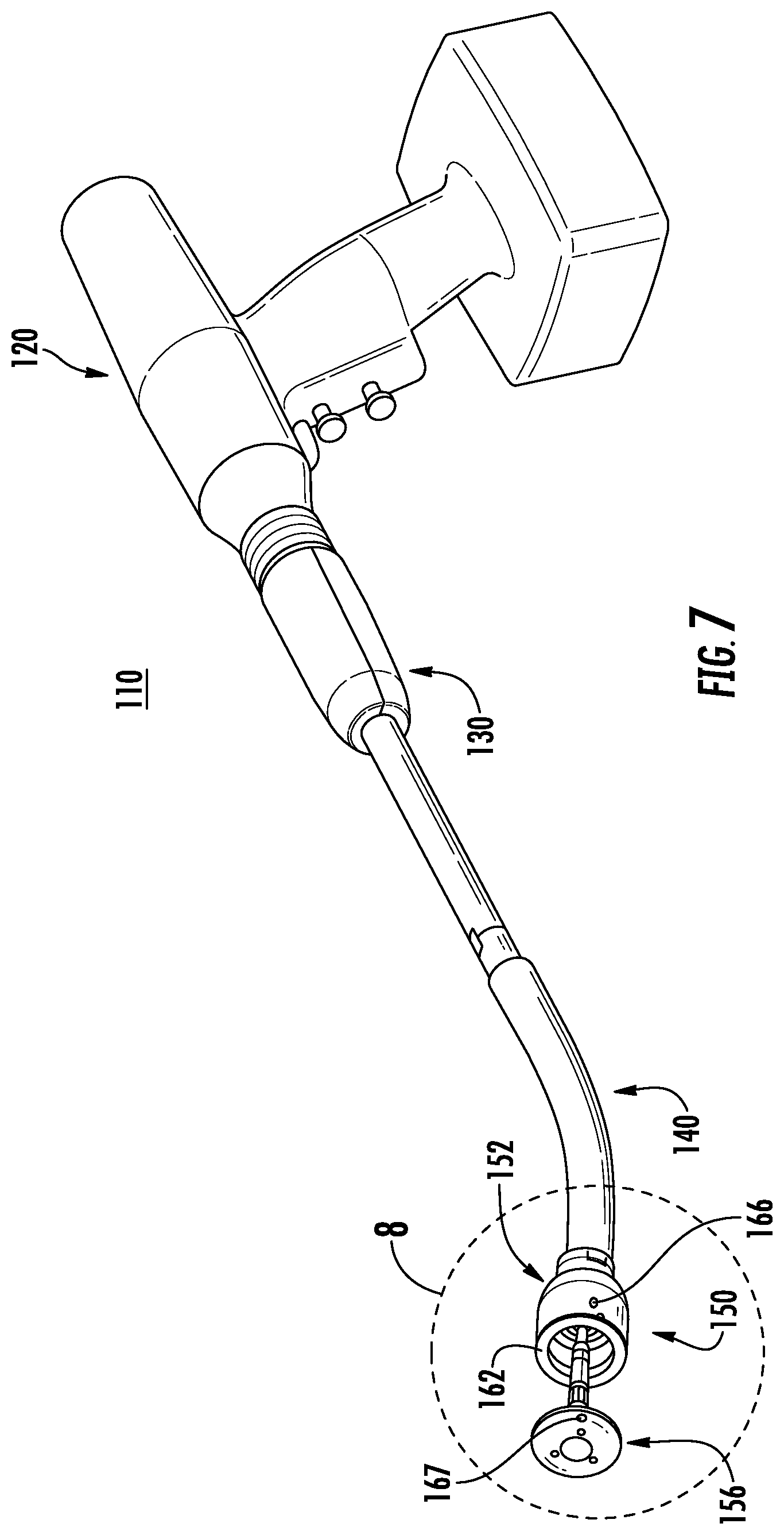
Referring now to FIG. 7, a surgical instrument 110 having a powered handle 120 including an annular or circular stapling end effector 150 is provided in accordance with another exemplary embodiment of the present disclosure. The surgical instrument 110 includes a powered handle 120, an adapter 130, a loading unit 140, and an end effector 150. The adapter 130 is releasably coupled to the powered handle 120 and extends from the powered handle 120. The loading unit 140 is releasably coupled to a distal end of the adapter 130. The end effector 150 is supported at a distal end of the loading unit 140 and includes a shell assembly 152 and an anvil assembly 156 that are moveable relative to one another. The powered handle 120 is configured to actuate the end effector 150 to approximate the shell and anvil assemblies 152, 156 of the end effector 150 relative to one another and to fire a plurality of fasteners (e.g., staples) through tissue positioned between the shell and anvil assemblies 152, 156. For a detailed description of the structure and function of an exemplary adapter and loading unit, please refer to commonly owned U.S. Provisional Patent Application Ser. No. 62/066,518 filed Oct. 21, 2014. For a detailed description of the structure and function of an exemplary powered handle, please refer to commonly owned U.S. Patent Publication No. 2012/0253329. Each of these applications is incorporated herein by reference in its entirety.
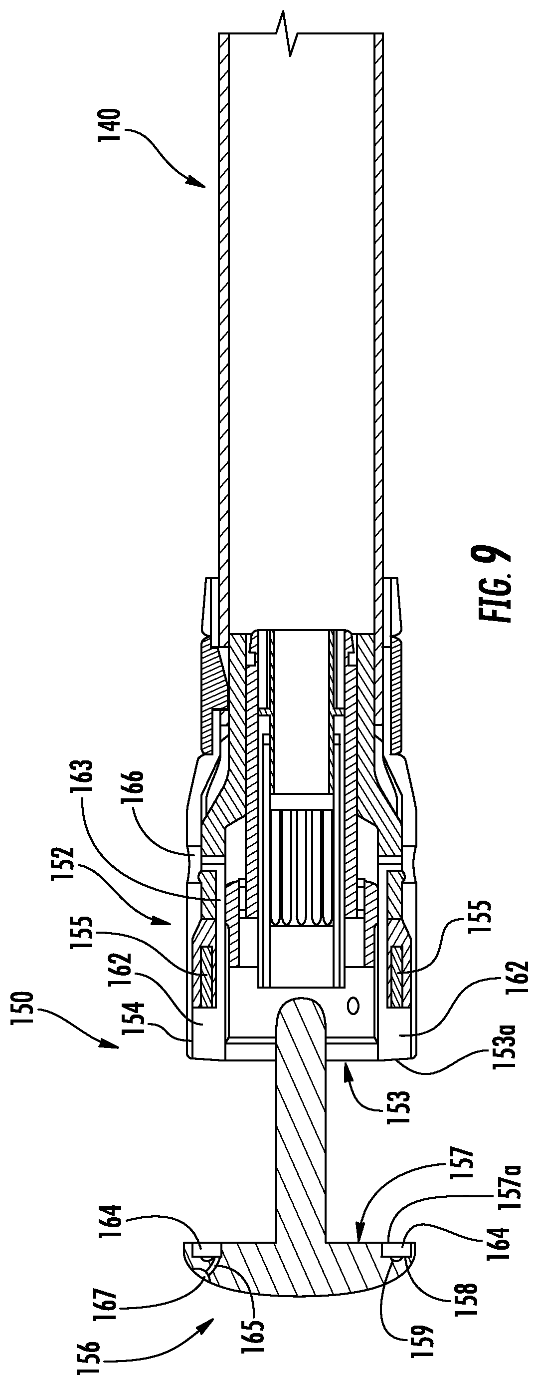
With reference to FIGS. 8 and 9, the first or shell assembly or member 152 has a tissue contacting surface 153 that defines an annular groove 154 with an outer surface of the shell assembly 152. The shell assembly 152 includes an integrated bladder 162 disposed within the annular groove 154 and positioned between a plurality of fasteners 155 and the tissue contacting surface 153. The integrated bladder 162 is defined between an outer film 153a disposed along the tissue contacting surface 153 and an inner film 153b disposed over the plurality of fasteners 155. The shell assembly 152 defines an injection port 166 that is in fluid communication with the integrated bladder 162 via a delivery tube 163.
Additionally or alternatively, the anvil assembly 156 has a tissue contacting surface 157 defines an annular groove 158. The annular groove 158 is positioned between the tissue contacting surface 157 and staple pockets 159 or retainers (not shown) of the anvil assembly 156. The anvil assembly 156 includes an integrated bladder 164 disposed within the annular groove 158. The integrated bladder 164 is defined between an outer film 157a and the staple pockets 159. The distal surface of the anvil assembly 156 may define a second injection port 167 that is in fluid communication with the integrated bladder 164 via a delivery tube 165.
With reference to FIGS. 8-10, the integrated bladders 162, 164 have an unfilled configuration (FIG. 9) and a filled configuration (FIG. 10) which are substantially similar to the unfilled and filled configurations of the integrated bladders 62, 64 detailed above. As shown, the integrated bladders 162, 164 have semi-rigid walls; however, it is contemplated that integrated bladders 162, 164 may have collapsible walls as detailed above with respect to integrated bladders 62, 64.
With reference to FIG. 10 and similar to the integrated bladders 62, 64 as detailed above with respect to the linear end effector 50, the integrated bladders 162, 164 of the circular end effector 150 coat the fasteners 155 and the tissue T as the fasteners 155 are driven through the integrated bladder 162 of the shell assembly 152 to pierce the integrated bladder 162 and to secrete fluid from the integrated bladder 164 of the anvil assembly 156 as the fasteners 155 pierce the integrated bladder 164.
In any of the embodiments disclosed herein, the instrument could have channels for conveying the fluid. In such embodiments, the channels would dispense the fluid whether or not the buttress was present.
While several embodiments of the disclosure have been shown in the drawings, it is not intended that the disclosure be limited thereto, as it is intended that the disclosure be as broad in scope as the art will allow and that the specification be read likewise. Any combination of the above embodiments is also envisioned and is within the scope of the appended claims. Therefore, the above description should not be construed as limiting, but merely as exemplifications of particular embodiments. Those skilled in the art will envision other modifications within the scope of the claims appended hereto.
* * * * *
D00000
D00001
D00002
D00003
D00004
D00005
D00006
D00007
D00008
D00009
XML
uspto.report is an independent third-party trademark research tool that is not affiliated, endorsed, or sponsored by the United States Patent and Trademark Office (USPTO) or any other governmental organization. The information provided by uspto.report is based on publicly available data at the time of writing and is intended for informational purposes only.
While we strive to provide accurate and up-to-date information, we do not guarantee the accuracy, completeness, reliability, or suitability of the information displayed on this site. The use of this site is at your own risk. Any reliance you place on such information is therefore strictly at your own risk.
All official trademark data, including owner information, should be verified by visiting the official USPTO website at www.uspto.gov. This site is not intended to replace professional legal advice and should not be used as a substitute for consulting with a legal professional who is knowledgeable about trademark law.