Suture anchor and associated methods of use
Pilgeram , et al. May 18, 2
U.S. patent number 11,006,945 [Application Number 15/964,206] was granted by the patent office on 2021-05-18 for suture anchor and associated methods of use. This patent grant is currently assigned to Stryker Corporation. The grantee listed for this patent is Stryker Corporation. Invention is credited to Ross Callison, Charles McCartney, Anthony P. Napolitano, Kyle Craig Pilgeram, Harold D. Sampson, Jr..


| United States Patent | 11,006,945 |
| Pilgeram , et al. | May 18, 2021 |
Suture anchor and associated methods of use
Abstract
A method for securing a sleeve in a bore hole in bone. The method includes disposing at least a portion of a length of filament into the bore hole, and implanting the sleeve into the bore hole such that a first pathway extending through first and second ends of the sleeve opens in a direction toward the opening of the bore hole and in a direction toward the base of the bore hole. The method also includes pulling at least a portion of the length of filament through the first pathway of the sleeve, thereby forming a first loop configuration extending from the first end and at least one free end of the length of filament extending from the second end. Also included is passing the at least one free end through the first loop configuration to create a one-way cinch.
| Inventors: | Pilgeram; Kyle Craig (San Jose, CA), McCartney; Charles (Denver, CO), Sampson, Jr.; Harold D. (Lone Tree, CO), Callison; Ross (Denver, CO), Napolitano; Anthony P. (Chappaqua, NY) | ||||||||||
|---|---|---|---|---|---|---|---|---|---|---|---|
| Applicant: |
|
||||||||||
| Assignee: | Stryker Corporation (Kalamazoo,
MI) |
||||||||||
| Family ID: | 1000005557609 | ||||||||||
| Appl. No.: | 15/964,206 | ||||||||||
| Filed: | April 27, 2018 |
Prior Publication Data
| Document Identifier | Publication Date | |
|---|---|---|
| US 20180242966 A1 | Aug 30, 2018 | |
Related U.S. Patent Documents
| Application Number | Filing Date | Patent Number | Issue Date | ||
|---|---|---|---|---|---|
| 14525636 | Oct 28, 2014 | 9986992 | |||
| Current U.S. Class: | 1/1 |
| Current CPC Class: | A61B 17/0485 (20130101); A61F 2/0811 (20130101); A61B 17/0401 (20130101); A61B 2017/0458 (20130101); A61B 2017/0403 (20130101); A61F 2002/0888 (20130101); A61B 2017/0409 (20130101); A61F 2002/0852 (20130101) |
| Current International Class: | A61B 17/04 (20060101); A61F 2/08 (20060101) |
References Cited [Referenced By]
U.S. Patent Documents
| 749624 | January 1904 | McCullough |
| 1308798 | July 1919 | Masland |
| 1624530 | April 1927 | Caruso |
| 2073903 | March 1937 | O'Neil |
| 2250434 | July 1941 | Dugaw |
| 2267925 | December 1941 | Johnston |
| 2382019 | August 1945 | Miller |
| 2461947 | February 1949 | Weber |
| 2494229 | January 1950 | Collison |
| 2515365 | July 1950 | Zublin |
| 2547571 | April 1951 | Ettinger |
| 2773672 | December 1956 | Holmes et al. |
| 2808632 | October 1957 | Cline |
| 2833284 | May 1958 | Springer |
| 3384085 | May 1968 | Hall |
| 3407889 | October 1968 | Hjalsten et al. |
| 3461875 | August 1969 | Hall |
| 3554192 | January 1971 | Isberner |
| 3580256 | May 1971 | Wilkinson et al. |
| 3608095 | September 1971 | Barry |
| 3659597 | May 1972 | Wolfers |
| 3750671 | August 1973 | Hedrick |
| 3810456 | May 1974 | Karman |
| 3845772 | November 1974 | Smith |
| 3867932 | February 1975 | Huene |
| 3892232 | July 1975 | Neufeld |
| 3976079 | August 1976 | Samuels et al. |
| 3981051 | September 1976 | Brumlik |
| 4212569 | July 1980 | Andersson et al. |
| 4265231 | May 1981 | Scheller, Jr. et al. |
| 4328839 | May 1982 | Lyons et al. |
| 4483562 | November 1984 | Schoolman |
| 4489446 | December 1984 | Reed |
| 4541423 | September 1985 | Barber |
| 4594033 | June 1986 | Peetz et al. |
| 4605347 | August 1986 | Jodock et al. |
| 4608972 | September 1986 | Small |
| 4611515 | September 1986 | Marbourg, Jr. |
| 4635738 | January 1987 | Schillinger et al. |
| 4646738 | March 1987 | Trott |
| 4706659 | November 1987 | Matthews et al. |
| 4728231 | March 1988 | Kunimori et al. |
| 4741330 | May 1988 | Hayhurst |
| 4748872 | June 1988 | Brown |
| 4751922 | June 1988 | DiPietropolo |
| 4781182 | November 1988 | Purnell et al. |
| 4823780 | April 1989 | Odensten et al. |
| 4842451 | June 1989 | Dugger |
| 4863471 | September 1989 | Mansat |
| 4872451 | October 1989 | Moore et al. |
| 4946462 | August 1990 | Watanabe |
| 5002546 | March 1991 | Romano |
| 5007911 | April 1991 | Baker |
| 5021059 | June 1991 | Kensey et al. |
| 5030219 | July 1991 | Matsen, III et al. |
| 5037422 | August 1991 | Hayhurst et al. |
| 5037423 | August 1991 | Kenna |
| 5061277 | October 1991 | Carpentier et al. |
| 5064431 | November 1991 | Gilbertson et al. |
| 5122134 | June 1992 | Borzone et al. |
| 5123914 | June 1992 | Cope |
| 5133720 | July 1992 | Greenberg |
| 5139520 | August 1992 | Rosenberg |
| 5141520 | August 1992 | Goble et al. |
| 5163940 | November 1992 | Bourque |
| 5165494 | November 1992 | Barr |
| 5186268 | February 1993 | Clegg |
| 5190548 | March 1993 | Davis |
| 5203595 | April 1993 | Borzone et al. |
| 5203787 | April 1993 | Noblitt et al. |
| RE34293 | June 1993 | Goble et al. |
| 5234435 | August 1993 | Seagrave, Jr. |
| 5259846 | November 1993 | Granger et al. |
| 5269785 | December 1993 | Bonutti |
| 5269809 | December 1993 | Hayhurst et al. |
| 5273380 | December 1993 | Musacchia |
| 5300077 | April 1994 | Howell |
| 5314429 | May 1994 | Goble |
| 5320115 | June 1994 | Kenna |
| 5320626 | June 1994 | Schmieding |
| 5324308 | June 1994 | Pierce |
| 5330468 | July 1994 | Burkhart |
| 5342376 | August 1994 | Ruff |
| 5350383 | September 1994 | Schmieding et al. |
| RE34762 | October 1994 | Goble et al. |
| 5374269 | December 1994 | Rosenberg |
| 5385567 | January 1995 | Goble |
| 5391170 | February 1995 | McGuire et al. |
| 5391171 | February 1995 | Schmieding |
| RE34871 | March 1995 | McGuire et al. |
| 5395188 | March 1995 | Bailey et al. |
| 5403317 | April 1995 | Bonutti |
| 5403348 | April 1995 | Bonutti |
| 5405359 | April 1995 | Pierce |
| 5409494 | April 1995 | Morgan |
| 5417691 | May 1995 | Hayhurst |
| 5423824 | June 1995 | Akerfeldt et al. |
| 5423860 | June 1995 | Lizardi et al. |
| 5437630 | August 1995 | Daniel et al. |
| 5437675 | August 1995 | Wilson |
| 5437677 | August 1995 | Shearer et al. |
| 5441502 | August 1995 | Bartlett |
| 5443482 | August 1995 | Stone et al. |
| 5458604 | October 1995 | Schmieding |
| 5464407 | November 1995 | McGuire |
| 5464425 | November 1995 | Skiba |
| 5464426 | November 1995 | Bonutti |
| 5466243 | November 1995 | Schmieding et al. |
| 5472452 | December 1995 | Trott |
| 5486197 | January 1996 | Le et al. |
| 5488761 | February 1996 | Leone |
| 5496348 | March 1996 | Bonutti |
| 5505736 | April 1996 | Reimels et al. |
| 5520693 | May 1996 | McGuire et al. |
| 5520700 | May 1996 | Beyar et al. |
| 5522846 | June 1996 | Bonutti |
| 5527316 | June 1996 | Stone et al. |
| 5527343 | June 1996 | Bonutti |
| 5529580 | June 1996 | Kusunoki et al. |
| 5531759 | July 1996 | Kensey et al. |
| 5534012 | July 1996 | Bonutti |
| 5540703 | July 1996 | Barker, Jr. et al. |
| 5545178 | August 1996 | Kensey et al. |
| 5548862 | August 1996 | Curtis |
| 5569269 | October 1996 | Hart et al. |
| 5569306 | October 1996 | Thal |
| 5570706 | November 1996 | Howell |
| 5571111 | November 1996 | Aboczky |
| 5573542 | November 1996 | Stevens |
| 5575819 | November 1996 | Amis |
| 5584617 | December 1996 | Houser |
| 5584695 | December 1996 | Lal Sachdeva et al. |
| 5584835 | December 1996 | Greenfield |
| 5601550 | February 1997 | Esser |
| 5601557 | February 1997 | Hayhurst |
| 5601561 | February 1997 | Terry et al. |
| 5618314 | April 1997 | Harwin et al. |
| 5645545 | July 1997 | Bryant |
| 5645589 | July 1997 | Li |
| 5647874 | July 1997 | Hayhurst |
| 5649963 | July 1997 | McDevitt |
| 5658289 | August 1997 | Boucher et al. |
| 5658313 | August 1997 | Thal |
| 5662658 | September 1997 | Wenstrom, Jr. |
| 5664914 | September 1997 | Taniguchi |
| 5665110 | September 1997 | Chervitz et al. |
| 5665111 | September 1997 | Ray et al. |
| 5665112 | September 1997 | Thal |
| 5667509 | September 1997 | Westin |
| 5671695 | September 1997 | Schroeder |
| 5674279 | October 1997 | Wright et al. |
| 5681315 | October 1997 | Szabo |
| 5681320 | October 1997 | McGuire |
| 5681352 | October 1997 | Clancy, III et al. |
| 5683401 | November 1997 | Schmieding et al. |
| 5683418 | November 1997 | Luscombe et al. |
| 5683419 | November 1997 | Thal |
| 5690676 | November 1997 | DiPoto et al. |
| 5690677 | November 1997 | Schmieding et al. |
| 5695513 | December 1997 | Johnson et al. |
| 5699657 | December 1997 | Paulson |
| 5702397 | December 1997 | Goble et al. |
| 5707374 | January 1998 | Schmidt |
| 5709708 | January 1998 | Thal |
| 5713905 | February 1998 | Goble et al. |
| 5716397 | February 1998 | Myers |
| 5718717 | February 1998 | Bonutti |
| 5720765 | February 1998 | Thal |
| 5725530 | March 1998 | Popken |
| 5725541 | March 1998 | Anspach, III et al. |
| 5725557 | March 1998 | Gatturna et al. |
| 5728136 | March 1998 | Thal |
| 5732606 | March 1998 | Chiang |
| 5733306 | March 1998 | Bonutti |
| 5733307 | March 1998 | Dinsdale |
| 5749899 | May 1998 | Bardin et al. |
| 5755724 | May 1998 | Yoon |
| 5755731 | May 1998 | Grinberg |
| 5766221 | June 1998 | Benderev et al. |
| 5782862 | July 1998 | Bonutti |
| 5782864 | July 1998 | Lizardi |
| 5782866 | July 1998 | Wenstrom, Jr. |
| 5788699 | August 1998 | Bobst et al. |
| 5797918 | August 1998 | McGuire et al. |
| 5810825 | September 1998 | Huebner |
| 5814056 | September 1998 | Prosst et al. |
| 5820464 | October 1998 | Parlato |
| 5836953 | November 1998 | Yoon |
| 5851208 | December 1998 | Trott |
| 5885294 | March 1999 | Pedlick et al. |
| 5888034 | March 1999 | Greenberg |
| 5891168 | April 1999 | Thal |
| 5895179 | April 1999 | Gschwend et al. |
| 5897574 | April 1999 | Bonutti |
| 5906626 | May 1999 | Carrillo |
| 5908423 | June 1999 | Kashuba et al. |
| 5921986 | July 1999 | Bonutti |
| 5928244 | July 1999 | Tovey et al. |
| 5941139 | August 1999 | Vodehnal |
| 5941883 | August 1999 | Sklar |
| 5947659 | September 1999 | Mays |
| 5948002 | September 1999 | Bonutti |
| 5951559 | September 1999 | Burkhart |
| 5954747 | September 1999 | Clark |
| 5968078 | October 1999 | Grotz |
| 5970697 | October 1999 | Jacobs et al. |
| 5980539 | November 1999 | Kontos |
| 5980558 | November 1999 | Wiley |
| 5980559 | November 1999 | Bonutti |
| 5989252 | November 1999 | Fumex |
| 5993451 | November 1999 | Burkhart |
| 5997541 | December 1999 | Schenk |
| 6007566 | December 1999 | Wenstrom, Jr. |
| 6007567 | December 1999 | Bonutti |
| 6010515 | January 2000 | Swain et al. |
| 6010525 | January 2000 | Bonutti et al. |
| 6019767 | February 2000 | Howell |
| 6024758 | February 2000 | Thal |
| 6030406 | February 2000 | Davis et al. |
| 6045574 | April 2000 | Thal |
| 6053922 | April 2000 | Krause et al. |
| 6068642 | May 2000 | Johnson et al. |
| 6077292 | June 2000 | Bonutti |
| 6083244 | July 2000 | Lubbers et al. |
| 6083522 | July 2000 | Chu et al. |
| 6120511 | September 2000 | Chan |
| 6143017 | November 2000 | Thal |
| 6146385 | November 2000 | Torrie et al. |
| 6152949 | November 2000 | Bonutti |
| 6156039 | December 2000 | Thal |
| 6156056 | December 2000 | Kearns et al. |
| 6159234 | December 2000 | Bonutti et al. |
| 6183461 | February 2001 | Matsuura et al. |
| 6187011 | February 2001 | Torrie |
| 6189422 | February 2001 | Stihl |
| 6210415 | April 2001 | Bester |
| 6224608 | May 2001 | Ciccolella et al. |
| 6245081 | June 2001 | Bowman et al. |
| 6254604 | July 2001 | Howell |
| 6258093 | July 2001 | Edwards et al. |
| 6270501 | August 2001 | Freiberg et al. |
| 6296659 | October 2001 | Foerster |
| 6306138 | October 2001 | Clark et al. |
| 6306159 | October 2001 | Schwartz et al. |
| 6312438 | November 2001 | Adams |
| 6343482 | February 2002 | Endo et al. |
| 6352538 | March 2002 | McGuire et al. |
| 6358253 | March 2002 | Torrie et al. |
| 6364886 | April 2002 | Sklar |
| 6383188 | May 2002 | Kuslich et al. |
| 6416517 | July 2002 | Harder et al. |
| 6419678 | July 2002 | Asfora |
| 6419684 | July 2002 | Heisler et al. |
| 6431801 | August 2002 | Vasudeva et al. |
| 6436100 | August 2002 | Berger |
| 6436124 | August 2002 | Anderson et al. |
| 6440138 | August 2002 | Reiley et al. |
| 6440141 | August 2002 | Philippon |
| 6447518 | September 2002 | Krause et al. |
| 6464713 | October 2002 | Bonutti |
| 6474425 | November 2002 | Truax et al. |
| 6475230 | November 2002 | Bonutti et al. |
| 6478800 | November 2002 | Fraser et al. |
| 6485504 | November 2002 | Johnson et al. |
| 6494272 | December 2002 | Eppink et al. |
| 6500195 | December 2002 | Bonutti |
| RE37963 | January 2003 | Thal |
| 6508830 | January 2003 | Steiner |
| 6511498 | January 2003 | Fumex |
| 6517578 | February 2003 | Hein |
| 6544281 | April 2003 | ElAttrache et al. |
| 6558386 | May 2003 | Cragg |
| 6558390 | May 2003 | Cragg |
| 6569187 | May 2003 | Bonutti et al. |
| 6572635 | June 2003 | Bonutti |
| 6575979 | June 2003 | Cragg |
| 6599310 | July 2003 | Leung et al. |
| 6610080 | August 2003 | Morgan |
| 6635073 | October 2003 | Bonutti |
| 6638279 | October 2003 | Bonutti |
| 6638283 | October 2003 | Thal |
| 6641597 | November 2003 | Burkhart et al. |
| 6660023 | December 2003 | McDevitt et al. |
| 6712822 | March 2004 | Re et al. |
| 6716234 | April 2004 | Grafton et al. |
| 6730092 | May 2004 | Songer |
| 6740090 | May 2004 | Cragg et al. |
| 6746451 | June 2004 | Middleton et al. |
| 6773450 | August 2004 | Leung et al. |
| 6780188 | August 2004 | Clark et al. |
| 6783533 | August 2004 | Green et al. |
| 6790210 | September 2004 | Cragg et al. |
| 6805697 | October 2004 | Helm et al. |
| 6824552 | November 2004 | Robison et al. |
| 6830570 | December 2004 | Frey et al. |
| 6848152 | February 2005 | Genova et al. |
| 6863672 | March 2005 | Reiley et al. |
| 6874978 | April 2005 | Gongola |
| 6878150 | April 2005 | McGuire et al. |
| 6887259 | May 2005 | Lizardi |
| 6893445 | May 2005 | Revie et al. |
| 6899716 | May 2005 | Cragg |
| 6921403 | July 2005 | Cragg et al. |
| 6923811 | August 2005 | Carl et al. |
| 6923814 | August 2005 | Hildebrand et al. |
| 6936052 | August 2005 | Gellman et al. |
| 6955683 | October 2005 | Bonutti |
| 6960214 | November 2005 | Burkinshaw |
| 6984241 | January 2006 | Lubbers et al. |
| 6991636 | January 2006 | Rose |
| 6994719 | February 2006 | Grafton |
| 6994725 | February 2006 | Goble |
| 6995683 | February 2006 | Smithson et al. |
| 7008431 | March 2006 | Simonson |
| 7018144 | March 2006 | Sasagawa et al. |
| 7025770 | April 2006 | McGuire et al. |
| 7029479 | April 2006 | Tallarida et al. |
| 7029490 | April 2006 | Grafton et al. |
| 7041107 | May 2006 | Pohjonen et al. |
| 7048754 | May 2006 | Martin et al. |
| 7056331 | June 2006 | Kaplan et al. |
| 7060073 | June 2006 | Frey et al. |
| 7067132 | June 2006 | Grabstein et al. |
| 7077863 | July 2006 | Schmieding et al. |
| 7087058 | August 2006 | Cragg |
| 7087073 | August 2006 | Bonutti |
| 7204839 | April 2007 | Dreyfuss et al. |
| 7217279 | May 2007 | Reese |
| 7217290 | May 2007 | Bonutti |
| 7225512 | June 2007 | Genova et al. |
| 7235091 | June 2007 | Thornes |
| 7241297 | July 2007 | Shaolian et al. |
| 7258692 | August 2007 | Thelen et al. |
| 7261016 | August 2007 | Miller |
| 7285124 | October 2007 | Foerster |
| 7309338 | December 2007 | Cragg |
| 7326215 | February 2008 | Myers et al. |
| 7331263 | February 2008 | Erickson et al. |
| 7371253 | May 2008 | Leung et al. |
| 7381213 | June 2008 | Lizardi |
| 7488322 | February 2009 | Brunnett et al. |
| 7488329 | February 2009 | Thelen et al. |
| 7494490 | February 2009 | Justin |
| 7500977 | March 2009 | Assell et al. |
| 7503920 | March 2009 | Siegal |
| 7520898 | April 2009 | Re et al. |
| 7563266 | July 2009 | Camino et al. |
| 7578836 | August 2009 | Justin et al. |
| 7585300 | September 2009 | Cha |
| 7601155 | October 2009 | Petersen |
| 7601165 | October 2009 | Stone |
| 7604636 | October 2009 | Walters et al. |
| 7608098 | October 2009 | Stone et al. |
| 7611521 | November 2009 | Lubbers et al. |
| 7621912 | November 2009 | Harms et al. |
| 7621940 | November 2009 | Harms et al. |
| 7624487 | December 2009 | Trull et al. |
| 7651509 | January 2010 | Bojarski et al. |
| 7651515 | January 2010 | Mack et al. |
| 7658751 | February 2010 | Stone et al. |
| 7666189 | February 2010 | Gerber et al. |
| 7678134 | March 2010 | Schmieding et al. |
| 7749250 | July 2010 | Stone et al. |
| 7776049 | August 2010 | Curran et al. |
| 7803173 | September 2010 | Burkhart et al. |
| 7857829 | December 2010 | Kaplan et al. |
| 7857830 | December 2010 | Stone et al. |
| 7875057 | January 2011 | Cook et al. |
| 7875058 | January 2011 | Holmes, Jr. |
| 7879037 | February 2011 | Brunnett et al. |
| 7892235 | February 2011 | Ellis |
| 7892256 | February 2011 | Grafton et al. |
| 7901431 | March 2011 | Shumas |
| 7905903 | March 2011 | Stone et al. |
| 7905904 | March 2011 | Stone et al. |
| 7909547 | March 2011 | Jordan et al. |
| 7909851 | March 2011 | Stone et al. |
| 7913365 | March 2011 | Genova et al. |
| 7914539 | March 2011 | Stone et al. |
| 7918874 | April 2011 | Siegal |
| 7959650 | June 2011 | Kaiser et al. |
| 7963967 | June 2011 | Woods |
| 7981117 | July 2011 | Newton et al. |
| 7981140 | July 2011 | Burkhart |
| 7993369 | August 2011 | Dreyfuss |
| 7996967 | August 2011 | Genova et al. |
| 7996968 | August 2011 | Genova et al. |
| 8002733 | August 2011 | Kraft et al. |
| 8011072 | September 2011 | Genova et al. |
| 8015678 | September 2011 | Genova et al. |
| 8020263 | September 2011 | Genova et al. |
| 8028387 | October 2011 | Genova et al. |
| 8028388 | October 2011 | Genova et al. |
| 8032996 | October 2011 | Trull et al. |
| 8043253 | October 2011 | Kraft et al. |
| 8057500 | November 2011 | Mitusina |
| 8070750 | December 2011 | Wenstrom, Jr. et al. |
| 8083770 | December 2011 | Ruff et al. |
| 8088130 | January 2012 | Kaiser et al. |
| 8100940 | January 2012 | Leung et al. |
| 8109700 | February 2012 | Jordan et al. |
| 8114088 | February 2012 | Miller |
| 8118834 | February 2012 | Goraltchouk et al. |
| 8118836 | February 2012 | Denham et al. |
| 8123750 | February 2012 | Norton et al. |
| 8128640 | March 2012 | Harris et al. |
| 8128658 | March 2012 | Kaiser et al. |
| 8128669 | March 2012 | Bonutti |
| 8133231 | March 2012 | Martinek et al. |
| 8137382 | March 2012 | Denham et al. |
| 8147514 | April 2012 | Bonutti |
| 8162997 | April 2012 | Struhl |
| 8172846 | May 2012 | Brunnett et al. |
| 8216273 | July 2012 | Goraltchouk et al. |
| 8231654 | July 2012 | Kaiser et al. |
| 8231674 | July 2012 | Albertorio et al. |
| 8241305 | August 2012 | Stone |
| 8246652 | August 2012 | Ruff |
| 8267959 | September 2012 | Fallman |
| 8273106 | September 2012 | Stone et al. |
| 8292921 | October 2012 | Stone et al. |
| 8298262 | October 2012 | Stone et al. |
| 8303604 | November 2012 | Stone et al. |
| 8312942 | November 2012 | Ho et al. |
| 8317825 | November 2012 | Stone |
| 8337525 | December 2012 | Stone et al. |
| 8343187 | January 2013 | Lamson et al. |
| 8361113 | January 2013 | Stone et al. |
| 8366713 | February 2013 | Long et al. |
| 8394129 | March 2013 | Morgenstern Lopez et al. |
| 8398678 | March 2013 | Baker et al. |
| 8409253 | April 2013 | Stone et al. |
| 8439976 | May 2013 | Albertorio et al. |
| 8460338 | June 2013 | Goraltchouk et al. |
| 8460379 | June 2013 | Albertorio et al. |
| 8469998 | June 2013 | Sojka et al. |
| 8512340 | August 2013 | Easley et al. |
| 8518087 | August 2013 | Lopez et al. |
| 8562645 | October 2013 | Stone et al. |
| 8591578 | November 2013 | Albertorio et al. |
| 8597333 | December 2013 | Morgenstern Lopez et al. |
| 8623051 | January 2014 | Bojarski et al. |
| 8663324 | March 2014 | Schmieding et al. |
| 8801800 | August 2014 | Bagga et al. |
| 8814905 | August 2014 | Sengun et al. |
| 8821543 | September 2014 | Hernandez et al. |
| 8821544 | September 2014 | Sengun et al. |
| 8821545 | September 2014 | Sengun |
| 9370350 | June 2016 | Norton |
| 9445803 | September 2016 | Marchand et al. |
| 9451938 | September 2016 | Overes et al. |
| 2001/0002436 | May 2001 | Bowman et al. |
| 2002/0019635 | February 2002 | Wenstrom et al. |
| 2002/0183758 | December 2002 | Middleton et al. |
| 2002/0188301 | December 2002 | Dallara et al. |
| 2003/0032961 | February 2003 | Pelo et al. |
| 2003/0176919 | September 2003 | Schmieding |
| 2003/0195565 | October 2003 | Bonutti |
| 2003/0220646 | November 2003 | Thelen et al. |
| 2003/0233098 | December 2003 | Markworth |
| 2004/0010264 | January 2004 | Acker et al. |
| 2004/0010287 | January 2004 | Bonutti |
| 2004/0030346 | February 2004 | Frey et al. |
| 2004/0073227 | April 2004 | Dreyfuss et al. |
| 2004/0073306 | April 2004 | Eichhorn et al. |
| 2004/0092933 | May 2004 | Shaolian et al. |
| 2004/0149093 | August 2004 | Tang |
| 2004/0193168 | September 2004 | Long et al. |
| 2004/0193217 | September 2004 | Lubbers et al. |
| 2004/0208717 | October 2004 | Greenhalgh |
| 2004/0260300 | December 2004 | Gorensek et al. |
| 2004/0267277 | December 2004 | Zannis et al. |
| 2005/0015153 | January 2005 | Goble et al. |
| 2005/0033362 | February 2005 | Grafton |
| 2005/0038427 | February 2005 | Perriello et al. |
| 2005/0070906 | March 2005 | Clark et al. |
| 2005/0080400 | April 2005 | Corcoran et al. |
| 2005/0137600 | June 2005 | Jacobs et al. |
| 2005/0137601 | June 2005 | Assell et al. |
| 2005/0143741 | June 2005 | Timmermans et al. |
| 2005/0177168 | August 2005 | Brunnett et al. |
| 2005/0187537 | August 2005 | Loeb et al. |
| 2005/0203527 | September 2005 | Carrison et al. |
| 2005/0228399 | October 2005 | Kubo et al. |
| 2005/0251159 | November 2005 | Ewers et al. |
| 2005/0251208 | November 2005 | Elmer et al. |
| 2005/0261604 | November 2005 | Stephens et al. |
| 2005/0283156 | December 2005 | Schmieding et al. |
| 2005/0288710 | December 2005 | Fallin et al. |
| 2006/0001518 | January 2006 | Hayashi et al. |
| 2006/0004369 | January 2006 | Patel et al. |
| 2006/0015108 | January 2006 | Bonutti |
| 2006/0015110 | January 2006 | Pepper |
| 2006/0074434 | April 2006 | Wenstrom et al. |
| 2006/0079904 | April 2006 | Thal |
| 2006/0100631 | May 2006 | Sullivan et al. |
| 2006/0155329 | July 2006 | Grafton et al. |
| 2006/0178748 | August 2006 | Dinger et al. |
| 2006/0189993 | August 2006 | Stone |
| 2006/0190042 | August 2006 | Stone et al. |
| 2006/0212055 | September 2006 | Karabey et al. |
| 2006/0247641 | November 2006 | Re et al. |
| 2006/0247642 | November 2006 | Stone et al. |
| 2006/0282085 | December 2006 | Stone et al. |
| 2006/0293689 | December 2006 | Miller et al. |
| 2007/0010843 | January 2007 | Green |
| 2007/0010857 | January 2007 | Sugimoto et al. |
| 2007/0032800 | February 2007 | Ortiz et al. |
| 2007/0093840 | April 2007 | Pacelli et al. |
| 2007/0185532 | August 2007 | Stone et al. |
| 2007/0191853 | August 2007 | Stone |
| 2007/0213734 | September 2007 | Bleich et al. |
| 2007/0213735 | September 2007 | Saadat et al. |
| 2007/0225721 | September 2007 | Thelen et al. |
| 2007/0233151 | October 2007 | Chudik |
| 2007/0255317 | November 2007 | Fanton et al. |
| 2007/0260259 | November 2007 | Fanton et al. |
| 2007/0276392 | November 2007 | Beyar et al. |
| 2007/0288023 | December 2007 | Pellegrino et al. |
| 2007/0288031 | December 2007 | Dreyfuss et al. |
| 2008/0004659 | January 2008 | Burkhart et al. |
| 2008/0009904 | January 2008 | Bourque et al. |
| 2008/0027446 | January 2008 | Stone et al. |
| 2008/0027457 | January 2008 | Dienst et al. |
| 2008/0046009 | February 2008 | Albertorio et al. |
| 2008/0058816 | March 2008 | Philippon et al. |
| 2008/0065080 | March 2008 | Assell et al. |
| 2008/0065092 | March 2008 | Assell et al. |
| 2008/0065114 | March 2008 | Stone et al. |
| 2008/0071282 | March 2008 | Assell et al. |
| 2008/0082127 | April 2008 | Stone et al. |
| 2008/0082128 | April 2008 | Stone |
| 2008/0109037 | May 2008 | Steiner et al. |
| 2008/0114364 | May 2008 | Goldin et al. |
| 2008/0114399 | May 2008 | Bonutti |
| 2008/0132932 | June 2008 | Hoeppner et al. |
| 2008/0140078 | June 2008 | Nelson et al. |
| 2008/0140092 | June 2008 | Stone et al. |
| 2008/0140093 | June 2008 | Stone et al. |
| 2008/0140116 | June 2008 | Bonutti |
| 2008/0147063 | June 2008 | Cauldwell et al. |
| 2008/0147064 | June 2008 | Cauldwell et al. |
| 2008/0147071 | June 2008 | Serra et al. |
| 2008/0154275 | June 2008 | Assell et al. |
| 2008/0161814 | July 2008 | McAllister et al. |
| 2008/0167660 | July 2008 | Moreau et al. |
| 2008/0188854 | August 2008 | Moser |
| 2008/0188935 | August 2008 | Saylor et al. |
| 2008/0243163 | October 2008 | Masseglia et al. |
| 2008/0249481 | October 2008 | Crainich et al. |
| 2008/0255613 | October 2008 | Kaiser et al. |
| 2008/0262544 | October 2008 | Burkhart |
| 2008/0275431 | November 2008 | Stone |
| 2008/0275453 | November 2008 | Lafosse et al. |
| 2008/0306483 | December 2008 | Iannarone |
| 2008/0312689 | December 2008 | Denham et al. |
| 2008/0319478 | December 2008 | Foerster et al. |
| 2009/0012526 | January 2009 | Fletcher |
| 2009/0018654 | January 2009 | Schmieding et al. |
| 2009/0024130 | January 2009 | Lombardo |
| 2009/0054928 | February 2009 | Denham et al. |
| 2009/0062854 | March 2009 | Kaiser et al. |
| 2009/0076514 | March 2009 | Haines |
| 2009/0082805 | March 2009 | Kaiser et al. |
| 2009/0099554 | April 2009 | Forster et al. |
| 2009/0105775 | April 2009 | Mitchell et al. |
| 2009/0131940 | May 2009 | Brunnett et al. |
| 2009/0138015 | May 2009 | Conner et al. |
| 2009/0138042 | May 2009 | Thal |
| 2009/0143784 | June 2009 | Petersen et al. |
| 2009/0149858 | June 2009 | Fanelli et al. |
| 2009/0157081 | June 2009 | Homan et al. |
| 2009/0157124 | June 2009 | Ferragamo et al. |
| 2009/0160112 | June 2009 | Ostrovsky |
| 2009/0171359 | July 2009 | Sterrett |
| 2009/0192468 | July 2009 | Stone |
| 2009/0194446 | August 2009 | Miller et al. |
| 2009/0198258 | August 2009 | Workman |
| 2009/0216238 | August 2009 | Stark |
| 2009/0216243 | August 2009 | Re |
| 2009/0222013 | September 2009 | Graf et al. |
| 2009/0234386 | September 2009 | Dean et al. |
| 2009/0234451 | September 2009 | Manderson |
| 2009/0240104 | September 2009 | Ogdahl et al. |
| 2009/0248029 | October 2009 | Paulos |
| 2009/0265002 | October 2009 | Re et al. |
| 2009/0306671 | December 2009 | McCormack et al. |
| 2009/0306711 | December 2009 | Stone et al. |
| 2009/0312763 | December 2009 | McCormack et al. |
| 2009/0312776 | December 2009 | Kaiser et al. |
| 2009/0312792 | December 2009 | Fallin et al. |
| 2009/0312793 | December 2009 | Huxel et al. |
| 2009/0318961 | December 2009 | Stone et al. |
| 2009/0326538 | December 2009 | Sennett et al. |
| 2010/0049196 | February 2010 | Re |
| 2010/0049202 | February 2010 | Re |
| 2010/0049203 | February 2010 | Re |
| 2010/0057045 | March 2010 | Albritton, IV et al. |
| 2010/0076440 | March 2010 | Pamichev et al. |
| 2010/0082033 | April 2010 | Germain |
| 2010/0087857 | April 2010 | Stone et al. |
| 2010/0121332 | May 2010 | Crainich et al. |
| 2010/0121333 | May 2010 | Crainich et al. |
| 2010/0145384 | June 2010 | Stone et al. |
| 2010/0152739 | June 2010 | Sidebotham et al. |
| 2010/0160962 | June 2010 | Dreyfuss et al. |
| 2010/0185238 | July 2010 | Cauldwell et al. |
| 2010/0185283 | July 2010 | Baird et al. |
| 2010/0191241 | July 2010 | McCormack et al. |
| 2010/0211075 | August 2010 | Stone |
| 2010/0241121 | September 2010 | Logan et al. |
| 2010/0249786 | September 2010 | Schmieding et al. |
| 2010/0262146 | October 2010 | Tulkis |
| 2010/0268275 | October 2010 | Stone et al. |
| 2010/0292731 | November 2010 | Gittings et al. |
| 2010/0292732 | November 2010 | Hirotsuka et al. |
| 2010/0292792 | November 2010 | Stone et al. |
| 2010/0298878 | November 2010 | Leung et al. |
| 2010/0298879 | November 2010 | Leung et al. |
| 2010/0305709 | December 2010 | Metzger et al. |
| 2010/0318122 | December 2010 | Leung et al. |
| 2011/0009902 | January 2011 | Leung et al. |
| 2011/0015674 | January 2011 | Howard et al. |
| 2011/0015675 | January 2011 | Howard et al. |
| 2011/0022083 | January 2011 | DiMatteo et al. |
| 2011/0022084 | January 2011 | Sengun et al. |
| 2011/0046625 | February 2011 | Boileau et al. |
| 2011/0054526 | March 2011 | Stone et al. |
| 2011/0087247 | April 2011 | Fung et al. |
| 2011/0087280 | April 2011 | Albertorio |
| 2011/0087284 | April 2011 | Stone et al. |
| 2011/0093010 | April 2011 | Genova et al. |
| 2011/0098727 | April 2011 | Kaiser et al. |
| 2011/0106089 | May 2011 | Brunnett et al. |
| 2011/0106153 | May 2011 | Stone et al. |
| 2011/0125189 | May 2011 | Stoll, Jr. et al. |
| 2011/0152927 | June 2011 | Deng et al. |
| 2011/0160767 | June 2011 | Stone et al. |
| 2011/0160768 | June 2011 | Stone et al. |
| 2011/0184516 | July 2011 | Baird et al. |
| 2011/0208194 | August 2011 | Steiner et al. |
| 2011/0208239 | August 2011 | Stone et al. |
| 2011/0208240 | August 2011 | Stone et al. |
| 2011/0213416 | September 2011 | Kaiser |
| 2011/0213417 | September 2011 | Foerster et al. |
| 2011/0218538 | September 2011 | Sherman et al. |
| 2011/0218625 | September 2011 | Berelsman et al. |
| 2011/0224799 | September 2011 | Stone |
| 2011/0264138 | October 2011 | Avelar et al. |
| 2011/0264140 | October 2011 | Lizardi et al. |
| 2011/0264141 | October 2011 | Denham et al. |
| 2011/0270278 | November 2011 | Overes et al. |
| 2011/0270293 | November 2011 | Malla et al. |
| 2011/0270306 | November 2011 | Denham et al. |
| 2011/0295279 | December 2011 | Stone et al. |
| 2011/0301708 | December 2011 | Stone et al. |
| 2011/0319896 | December 2011 | Papenfuss et al. |
| 2012/0004672 | January 2012 | Giap et al. |
| 2012/0041485 | February 2012 | Kaiser et al. |
| 2012/0041486 | February 2012 | Stone et al. |
| 2012/0046693 | February 2012 | Denham et al. |
| 2012/0053629 | March 2012 | Reiser et al. |
| 2012/0053630 | March 2012 | Denham et al. |
| 2012/0053641 | March 2012 | Meridew |
| 2012/0059417 | March 2012 | Norton et al. |
| 2012/0059418 | March 2012 | Denham et al. |
| 2012/0071976 | March 2012 | May et al. |
| 2012/0089193 | April 2012 | Stone et al. |
| 2012/0095470 | April 2012 | Kaiser et al. |
| 2012/0095556 | April 2012 | Re et al. |
| 2012/0109142 | May 2012 | Dayan |
| 2012/0109156 | May 2012 | Overes et al. |
| 2012/0109194 | May 2012 | Miller et al. |
| 2012/0116452 | May 2012 | Stone et al. |
| 2012/0123474 | May 2012 | Zajac et al. |
| 2012/0150203 | June 2012 | Brady et al. |
| 2012/0150297 | June 2012 | Denham et al. |
| 2012/0150301 | June 2012 | Gamache et al. |
| 2012/0165866 | June 2012 | Kaiser et al. |
| 2012/0165867 | June 2012 | Denham et al. |
| 2012/0165938 | June 2012 | Denham et al. |
| 2012/0172986 | July 2012 | Stone et al. |
| 2012/0179254 | July 2012 | Saliman |
| 2012/0180291 | July 2012 | Oren et al. |
| 2012/0197271 | August 2012 | Astorino et al. |
| 2012/0203231 | August 2012 | Long et al. |
| 2012/0203288 | August 2012 | Lange et al. |
| 2012/0209325 | August 2012 | Gagliano et al. |
| 2012/0239085 | September 2012 | Schlotterback et al. |
| 2012/0239086 | September 2012 | Reznik et al. |
| 2012/0245585 | September 2012 | Kaiser et al. |
| 2012/0253355 | October 2012 | Murray et al. |
| 2012/0265205 | October 2012 | Steiner et al. |
| 2012/0290002 | November 2012 | Astorino |
| 2012/0290004 | November 2012 | Lombardo et al. |
| 2012/0290006 | November 2012 | Collins et al. |
| 2012/0296345 | November 2012 | Wack et al. |
| 2012/0296427 | November 2012 | Conner et al. |
| 2012/0303046 | November 2012 | Stone et al. |
| 2013/0012962 | January 2013 | Stone |
| 2013/0018416 | January 2013 | Lombardo et al. |
| 2013/0023928 | January 2013 | Dreyfuss |
| 2013/0023929 | January 2013 | Sullivan et al. |
| 2013/0023930 | January 2013 | Stone et al. |
| 2013/0035698 | February 2013 | Stone et al. |
| 2013/0046341 | February 2013 | Stone et al. |
| 2013/0053897 | February 2013 | Brown et al. |
| 2013/0072989 | March 2013 | Overes et al. |
| 2013/0085568 | April 2013 | Smith et al. |
| 2013/0096611 | April 2013 | Sullivan |
| 2013/0096612 | April 2013 | Zajac et al. |
| 2013/0110165 | May 2013 | Burkhart et al. |
| 2013/0116730 | May 2013 | Denham et al. |
| 2013/0131722 | May 2013 | Marchand et al. |
| 2013/0158601 | June 2013 | Stone et al. |
| 2013/0165972 | June 2013 | Sullivan |
| 2013/0178898 | July 2013 | Arnett et al. |
| 2013/0190818 | July 2013 | Norton |
| 2013/0190819 | July 2013 | Norton |
| 2013/0237997 | September 2013 | Arai et al. |
| 2013/0238025 | September 2013 | Howard et al. |
| 2013/0245700 | September 2013 | Choinski |
| 2013/0268000 | October 2013 | Harner et al. |
| 2013/0296931 | November 2013 | Sengun |
| 2013/0317544 | November 2013 | Ferguson et al. |
| 2013/0325063 | December 2013 | Norton et al. |
| 2013/0345749 | December 2013 | Sullivan et al. |
| 2014/0039503 | February 2014 | Pilgeram |
| 2014/0081322 | March 2014 | Sengun et al. |
| 2014/0135835 | May 2014 | Stone et al. |
| 2014/0163679 | June 2014 | Re et al. |
| 2014/0188163 | July 2014 | Sengun |
| 2014/0257382 | September 2014 | McCartney |
| 2014/0364906 | December 2014 | Palese |
| 2713309 | Feb 2011 | CA | |||
| 3131496 | Feb 1983 | DE | |||
| 8903079 | May 1989 | DE | |||
| 4231101 | Mar 1994 | DE | |||
| 4243715 | Jul 1994 | DE | |||
| 19503504 | Mar 1996 | DE | |||
| 153831 | Sep 1985 | EP | |||
| 253526 | Jan 1988 | EP | |||
| 0440371 | Aug 1991 | EP | |||
| 0611551 | Aug 1994 | EP | |||
| 1155776 | Nov 2001 | EP | |||
| 1174584 | Jan 2002 | EP | |||
| 1369089 | Dec 2003 | EP | |||
| 1398455 | Mar 2004 | EP | |||
| 2277457 | Jan 2011 | EP | |||
| 2286742 | Feb 2011 | EP | |||
| 2544607 | Jan 2013 | EP | |||
| 2548519 | Jan 2013 | EP | |||
| 2596755 | May 2013 | EP | |||
| 2662030 | Nov 2013 | EP | |||
| 2662032 | Nov 2013 | EP | |||
| 1166884 | Nov 1958 | FR | |||
| 2606996 | May 1988 | FR | |||
| 2676638 | Nov 1992 | FR | |||
| 2093353 | Sep 1982 | GB | |||
| 9511631 | May 1995 | WO | |||
| 9628100 | Sep 1996 | WO | |||
| 9704908 | Feb 1997 | WO | |||
| 9722301 | Jun 1997 | WO | |||
| 0024327 | May 2000 | WO | |||
| 0044291 | Aug 2000 | WO | |||
| 0128457 | Apr 2001 | WO | |||
| 0160268 | Aug 2001 | WO | |||
| 03007861 | Jan 2003 | WO | |||
| 03086221 | Oct 2003 | WO | |||
| 2004092531 | Oct 2004 | WO | |||
| 2007/010389 | Jan 2007 | WO | |||
| 2008128075 | Oct 2008 | WO | |||
| 2009105880 | Sep 2009 | WO | |||
| 2011112371 | Sep 2011 | WO | |||
| 2012134999 | Oct 2012 | WO | |||
| 2012158583 | Nov 2012 | WO | |||
| 2013006820 | Jan 2013 | WO | |||
Other References
|
Australian Examination Report for Application No. 2013202699 dated Feb. 21, 2014. cited by applicant . BIOMET Sports Medicine: Micromax Flex Suture Anchor, (2008). cited by applicant . Boccaccini, et al., "Composite Surgical Sutures with Bioactive Glass Coating", J Biomed Mater Res Part B: Appl Biomater 67B, pp. 618-626, 2003. cited by applicant . Bretcanu, et al., "Bioactivity of degradable polymer sutures coated with bioactive glass", Journal of Materials Science: Materials in Medicine, vol. 15, 2004, pp. 893-899. cited by applicant . Burkinshaw, U.S. Appl. No. 60/418,545, filed Oct. 15, 2002. cited by applicant . Charles McCartney, U.S. Appl. No. 13/792,982, filed Mar. 11, 2013, titled "Filamentary Fixation Device and Assembly and Method of Assembly, Manufacture and Use". cited by applicant . Chen et al., European Cells and Materials, vol. 16, Supp. 4, p. 7, 2008. cited by applicant . Chen et al., Journal of Orthopaedic Research, pp. 1432-1438, Nov. 2009. cited by applicant . Chen et al., Poster No. 538, 54th Annual Meeting of the Orthopaedic Research Society, San Francisco, CA Mar. 2008. cited by applicant . Cole et al., American Journal of Sports Medicine, vol. XX, No. X, Apr. 2011, 10 pages. cited by applicant . Conmed: Linvatec: Shoulder Restoration System Y-Knot 1.3mm All Suture Anchor, .COPYRGT. 2011 Linvatec Corporation, a subsidiary of ConMed Corporation--CBR 3057 (4 pages). cited by applicant . European Search Report, EP 10173568, dated Nov. 30, 2010. cited by applicant . Extended European Search Report for Application No. EP 12164104 dated Jul. 11, 2012. cited by applicant . Extended European Search Report for Application No. EP14157129 dated Oct. 9, 2014. cited by applicant . Extended European Search Report for Application No. EP14157877 dated Jul. 4, 2016. cited by applicant . Extended European Search Report for Application No. EP14159656 dated Jun. 6, 2014. cited by applicant . HHS Tube, Fort Wayne Metals Research Products Corp., 2009, 2 pages. cited by applicant . Insall et al., The Journal of Bone and Joint Surgery, vol. 49B, No. 2, pp. 211-228, May 1967. cited by applicant . International Search Report and Written Opinion for Application No. PCT/US2012/024303 dated May 24, 2012. cited by applicant . International Search Report and Written Opinion for Application No. PCT/US2014/021231 dated Jun. 25, 2014. cited by applicant . International Search Report PCT/US2010/042264, dated Sep. 30, 2010. cited by applicant . Long et al., U.S. Appl. No. 13/368,730, filed Feb. 8, 2012, titled "Flexible Microdrilling Instrumentation, Kits and Methods". cited by applicant . Marchand et al., U.S. Appl. No. 13/303,849, filed Nov. 23, 2011, titled "Filamentary Suture Anchor". cited by applicant . Medtronic, The VISAO High-Speed Otologic Drill Catalog, 2007, 12 pages. cited by applicant . Partial European Search Report for Application No. EP14151822 dated May 16, 2014. cited by applicant . Partial European Search Report for Appln No. EP12193507 dated Jun. 30, 2017. cited by applicant . Perthes, German Surgery Periodical, vol. 85, Commermorative Publication, pp. 2-18, 1906. cited by applicant . Perthes, Uber Operationen bel habitueller Schulterluxaton, Deutsch Zeitschrift fur Chirurgie, vol. 85, 1906, pp. 199-227 (English translation provided.). cited by applicant . Pilgeram, Kyle Craig, U.S. Appl. No. 13/588,586, filed Aug. 17, 2012, titled "Soft Tissue Fixation Devices and Methods". cited by applicant . Pilgeram, Kyle Craig, U.S. Appl. No. 13/588,592, filed Aug. 17, 2012, titled "Surgical Instruments and Methods of Use". cited by applicant . Pilgeram, Kyle Craig, U.S. Appl. No. 13/783,804, filed Mar. 4, 2013, titled "Knotless Filamentary Fixation Devices, Assemblies and Systems and Methods of Assembly and Use". cited by applicant . Pilgeram, Kyle Craig, U.S. Appl. No. 61/679,336, filed Aug. 3, 2012, titled "Soft Tissue Fixation Device and Methods". cited by applicant . Stamboulis, et al., "Mechanical properties of biodegradable polymer sutures coated with bioactive glass", Journal of Materials Science: Materials in Medicine, vol. 13, 2002, pp. 843-848. cited by applicant . Steiner et al., U.S. Appl. No. 13/085,882, filed Apr. 13, 2011, titled "Flexible ACL Instrumentation, Kit and Method". cited by applicant . Sugaya et al., Journal of Bone and Joint Surgery, vol. 85-A, No. 5, pp. 878-884, May 2003. cited by applicant . U.S. Appl. No. 12/682,324, filed Sep. 7, 2010. cited by applicant . U.S. Appl. No. 13/070,692, filed Mar. 24, 2011. cited by applicant . U.S. Appl. No. 13/182,851, filed Jul. 14, 2011. cited by applicant . U.S. Appl. No. 13/799,773, filed Mar. 13, 2013. cited by applicant. |
Primary Examiner: Ho; Tan-Uyen T
Assistant Examiner: Igboko; Chima U
Attorney, Agent or Firm: Lerner, David, Littenberg, Krumholz & Mentlik, LLP
Parent Case Text
CROSS-REFERENCE TO RELATED APPLICATIONS
This application is a continuation of U.S. application Ser. No. 14/525,636, filed on Oct. 28, 2014, the disclosure of which is incorporated by reference.
Claims
The invention claimed is:
1. A suture anchor insertion assembly, comprising: an inserter having a proximal end, a distal end, and a length extending therebetween, the distal end having an aperture surrounded by a perimeter of the aperture, the perimeter of the aperture including a first portion and a second portion of the inserter, the first and second portions being separable from each other such that in a second configuration, a distance between the first and second portions is further than in a first configuration so that a gap is formed between the first and second portions in the second configuration allowing a filament captured within the aperture to be released from the aperture through the gap; and a bone anchor having a length extending between first and a second ends thereof and an opening extending along the length, the bone anchor being a filamentary sleeve and disposed over a portion of the length of the inserter such that the distal end of the inserter extends from a first end of the bone anchor.
2. The assembly of claim 1, wherein the first and second portions are curved towards each other such that, in the first position, respective distal ends of the first and second portions face each other.
3. The assembly of claim 2, wherein, in the second position, the distal ends of the first and second portions are positioned further apart from each other than in the first position such that the gap is formed between the distal ends.
4. The assembly of claim 1, wherein the inserter includes an elongate shaft and the bone anchor is positioned over the elongate shaft such that the elongate shaft extends through the opening of the bone anchor.
5. The assembly of claim 4, wherein the first and second portions extend from an end of the elongate shaft.
6. The assembly of claim 1, wherein the first and second portions are adapted to pass through the opening of the bone anchor.
7. A suture anchor insertion assembly comprising: an inserter having a proximal end, a distal end, and a length extending therebetween, the distal end having first and second members extending therefrom, the first and second members defining a perimeter of an aperture that extends between the first and second members, the first and second members having a first configuration in which the first and second members form a closed perimeter about the aperture so as to capture a filament within the perimeter, and a second configuration in which the first and second members form an open perimeter about the aperture so as to allow the filament to escape through a gap formed in the open perimeter; and a bone anchor being a filamentary sleeve and having a length extending between first and a second ends thereof and an opening extending along the length of the bone anchor, the inserter extending through the opening of the bone anchor so that the first and second members are positioned closer to the first end of the bone anchor than the second end thereof.
8. The assembly of claim 7, wherein, in the first configuration, the first and second members are continuous with each other, and in the second configuration, the first and second members are discontinuous with each other via the gap.
9. The assembly of claim 7, wherein, in the first configuration, distal ends of the first and second members contact each other, and in the second configuration, the distal ends of the first and second members do not contact each other.
10. The assembly of claim 7, wherein the inserter includes an elongate shaft and the bone anchor is positioned over the elongate shaft such that the elongate shaft extends through the opening of the bone anchor.
11. The assembly of claim 10, wherein the first and second members extend from an end of the elongate shaft.
12. The assembly of claim 7, wherein the first and second members are adapted to pass through the opening of the bone anchor.
13. A method of anchoring soft tissue to bone comprising: capturing a length of filament connected to soft tissue with a distal end of an inserter such that the length of filament extends through an aperture defined by the inserter; inserting the distal end of the inserter into a bone hole in a bone such that the aperture and a bone anchor positioned over a portion of a length of the inserter are positioned within the bone hole; releasing the filament through a gap formed in the distal end of the inserter adjacent to the aperture; and drawing the distal end of the inserter through the bone anchor from a first end to a second end thereof while the bone anchor remains positioned within the bone hole, the drawing step being performed before the releasing step so that a portion of the length of filament is positioned in the opening of the bone anchor.
14. The method of claim 13, wherein the drawings step includes moving an inner member relative to an outer sheath positioned over the inner member, the bone anchor being positioned over the inner member.
15. The method of claim 13, wherein the perimeter of the aperture includes a first portion of the perimeter and a second portion of the perimeter, wherein the gap is formed by the first and second portions of the aperture separating from one another.
16. The method of claim 13, forming the gap between first and second members of the distal end of the inserter, the first and second members defining a perimeter of the aperture.
Description
BACKGROUND OF THE INVENTION
Soft tissue structures, such as fibrocartilage, ligaments and tendons, facilitate connections between multiple anatomic components. Injuries can partially and/or completely sever such structures leading to immobility and/or dysfunction of the anatomic components. In one example, a shoulder injury may tear a portion of the rotator cuff from its connection to bone, leading to instability of the shoulder joint and causing the naturally tensioned tendon to slacken. In another example, a shoulder injury may separate a portion of the glenoid labrum from the underlying bony structure leading to joint instability.
In some instances surgery may be needed to repair or replace the damaged soft tissue, which often involves anchoring the tissue in its natural position until fully healed. Traditionally, this was achieved by tethering the damaged tissue with a filament to a metal or hardened polymer anchoring device fixed to a bony structure. However, in many instances, such traditional anchoring devices tend to be large in diameter, and must include sufficient material, or other additional structures, to withstand pullout forces. The size of such devices may limit implantation locations in the body, as sufficient bone mass is required to accommodate the device.
Recent trends in tissue anchoring have seen the emergence of "soft" devices, also referred to as "filamentary" fixation devices, in which the anchoring device itself may be constructed of filamentary material, such as suture or the like. Despite the many benefits these filamentary fixation devices provide, such devices, to date, cannot be used to perform knotless surgical procedures, that is, surgical procedures using filaments (such as sutures or the like) where the filament is secured without the need of tying knots, such as half hitches or the like. Further, such devices, while generally capable of being anchored in a smaller bone hole than traditional anchoring devices, may still require a hole too large for certain applications.
BRIEF SUMMARY OF THE INVENTION
Generally, the present disclosure relates to devices, systems, methods and kits for knotless tissue anchoring applications, and in particular, to knotless tissue anchoring applications utilizing a device anchored within a minimal bone hole.
In one aspect of the present disclosure, a method for securing a sleeve in a bore hole in bone, the bore hole having an opening, a base and a wall extending between the base and opening. The method includes disposing at least a portion of a length of filament into the bore hole, and implanting the sleeve into the bore hole such that a first pathway extending through first and second ends of the sleeve opens in a direction toward the opening of the bore hole and in a direction toward the base of the bore hole. The method also includes pulling at least a portion of the length of filament through the first pathway of the sleeve, thereby forming a first loop configuration extending from the first end and at least one free end of the length of filament extending from the second end. Further included in the method is passing the at least one free end through the first loop configuration to create a one-way cinch.
In addition, the length of filament may be adapted to apply tension to a tissue in working relationship with the length of filament. The sleeve may be made of filamentary material. Further, the sleeve may include a sidewall and a plurality of fenestrations extending through the sidewall into the first pathway. When the sleeve is implanted in the bore hole, each of the plurality of fenestrations may be disposed adjacent to and open towards the wall of the bore hole.
Further, the method may also include engaging the length of filament with an inserter device prior to the disposing step, and disengaging the inserter device from the length of filament after the pulling step. The inserter device may include a filament engagement element for engaging and retaining the length of filament, and disengaging the inserter device from the first loop configuration may include moving the filament engagement element from a first position to a second position to release the single length of filament.
Continuing with this aspect, the method may include tensioning the at least one free end such that the first loop configuration, with the at least one free end positioned therethrough, travels toward and into the first pathway of the sleeve. Further, the method may include, prior to the pulling step, pulling the at least one free end and the at least a portion of the length of filament into and through a second pathway in the sleeve from the first end of the sleeve, and maneuvering the at least one free end and the at least a portion of the length of filament around a boundary separating the first and second pathways. The boundary may be a tab formed from a portion of the sleeve. Also, the first and second pathways may intersect at at least one location along the length of the sleeve.
In another aspect of the present disclosure, a method for securing a sleeve in a bore hole in bone, the bore hole having a base, an opening, and a wall disposed between the base and opening. The method includes implanting the sleeve into the bore hole. The sleeve has a length defined between a first end and a second end and a first pathway extending along the length of the sleeve. The method also includes passing at least a portion of a length of filament through the first pathway from the second end through the first end such that the at least a portion of the length of filament forms a first loop configuration that extends from the first pathway at the first end and at least one free segment of the length of filament having a free end that extends from the second end. Additionally, the method includes passing the free end of the at least one free segment through the first loop configuration such that the first loop configuration, with the free end positioned therethrough, forms a one-way cinch.
In addition, the first loop configuration and the first end of the sleeve may trap the at least first free segment to form the one-way cinch. The method may also include, prior to the passing steps, engaging the at least a portion of the length of filament with an inserter device. Further, the method may include disengaging the inserter device from the length of filament after the step of passing the at least a portion of the length of filament through the first pathway to form the first loop configuration. Disengaging the inserter device from the first loop configuration may include actuating a filament engagement element to release the length of filament.
Continuing with this aspect, the sleeve may include an outer surface and a plurality of openings extending from the outer surface into the first pathway. When the sleeve is implanted in the bore hole, each of the plurality of openings may be disposed adjacent to and open towards the wall of the bore hole. The sleeve may also include a second pathway juxtaposed with the first pathway. Prior to passing the at least a portion of the length of filament through the first pathway, the method may include passing the free end and the at least a portion of the length of filament through the second pathway from the first end of the sleeve through the second end of the sleeve. The first and second pathways may intersect at at least one location along the length of the sleeve. The sleeve may be made of filamentary material.
In a further aspect of the present disclosure, a method for securing a sleeve in a bore hole in bone, the bore hole having a base, an opening, and a wall disposed between the base and opening. The method includes implanting the sleeve into the bore hole such that a first end of the sleeve is disposed adjacent the opening of the bore hole and a second end of the sleeve is disposed adjacent the base of the bore hole, such that in this position the sleeve stands in a vertical configuration within the bore hole. The method may also include passing a portion of filament into and along a first pathway of the sleeve, maneuvering the portion of filament around a boundary between the first pathway and a second pathway of the sleeve, forming a first loop configuration extending from the first end of the sleeve, passing the portion of filament through the first loop configuration forming a second loop configuration, and tensioning the portion of filament such that the first loop configuration is pulled towards the first end of the sleeve.
In yet another aspect of the present disclosure, a method for securing a sleeve in a bore hole in bone, the bore hole having a base, an opening, and a wall disposed between the base and opening. The method includes implanting a sleeve into the bore hole such that a first end of the sleeve is disposed adjacent the opening of the bore hole and a second end of the sleeve is disposed adjacent the base of the bore hole, such that in this position the sleeve stands in a vertical configuration within the bore hole. The method also includes passing a portion of filament into and through a first pathway of the sleeve such that the portion of filament forms a first loop configuration extending from the first pathway in a first direction and at least one filament free segment extends from the first pathway in a second direction. The at least one filament free segment has a free end. The method further includes passing the at least one free end of the length of filament through the first loop configuration, and tensioning the at least one free end such that the first loop configuration is pulled toward the first end of the sleeve and the first loop configuration and sleeve traps the at least one filament free segment.
BRIEF DESCRIPTION OF THE DRAWINGS
These and other features, aspects, and advantages of the present invention will become better understood with regard to the following description, appended claims, and accompanying drawings where:
FIG. 1A illustrates one embodiment of an inserter device.
FIG. 1B illustrates one embodiment of an anchoring sleeve in a first condition.
FIG. 1C illustrates the anchoring sleeve of FIG. 1B in a second condition.
FIG. 1D illustrates the anchoring sleeve of FIG. 1B in an alternative second condition.
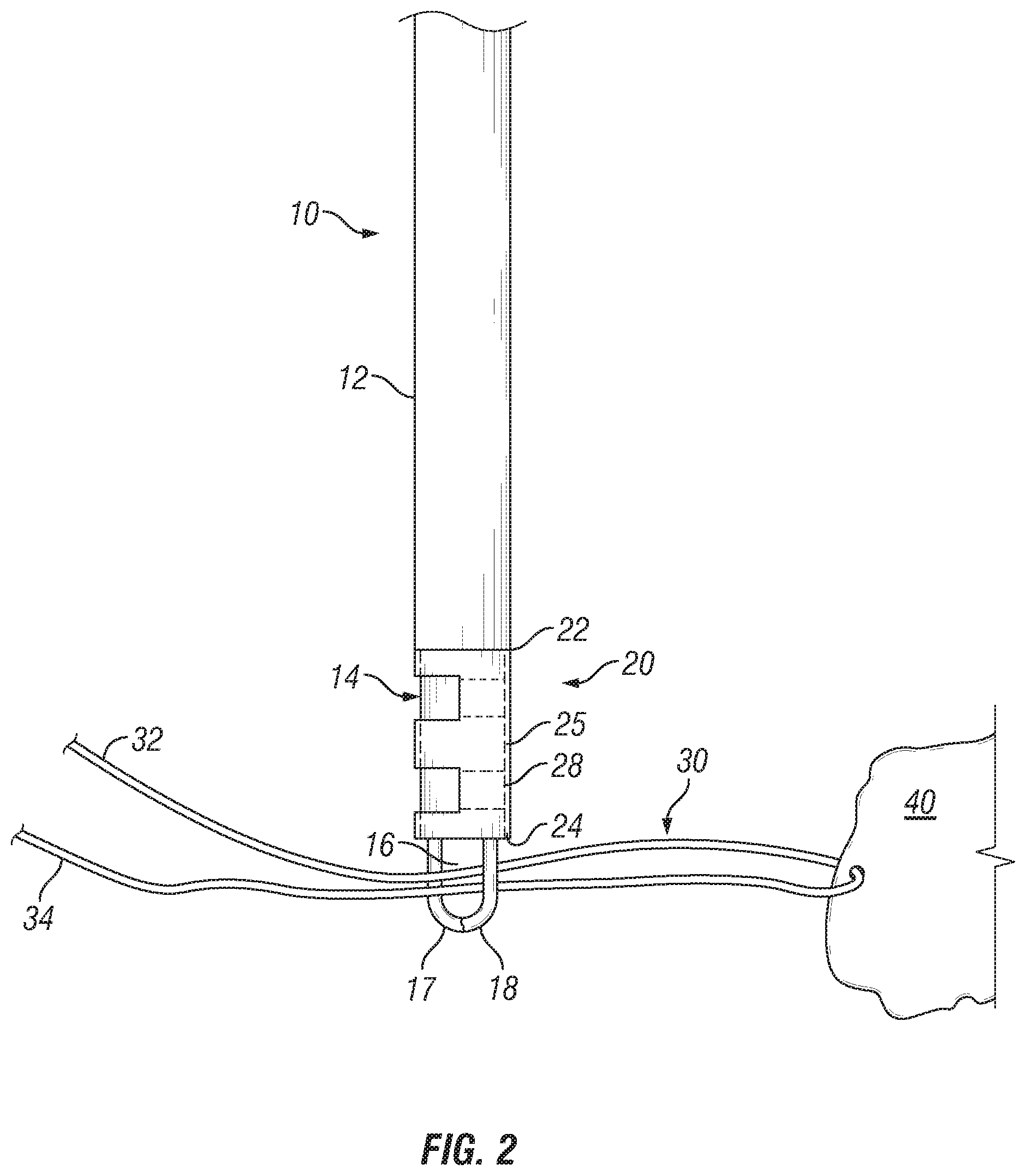
FIG. 2 illustrates a step of one embodiment of a method of use of the inserter and anchoring sleeve of FIGS. 1A and 1B or a method of assembly of an anchoring assembly.
FIG. 3 illustrates another step of the method embodiment of FIG. 2.
FIG. 4 illustrates an additional step of the method embodiment of FIGS. 2 and 3.
FIG. 5 illustrates a further step of the method embodiment of FIGS. 2-4.
FIG. 6 illustrates yet another step of the method embodiment of FIGS. 2-5.
FIG. 7 illustrates a still further step of the method embodiment of FIGS. 2-6.
FIG. 8 illustrates an alternative method of use or assembly.
FIG. 9 illustrates another embodiment of an anchoring sleeve and an alternative method of use or assembly.
FIGS. 10-12 illustrate another embodiment of an inserter device and method of use or assembly.
DETAILED DESCRIPTION
The anchoring devices, assemblies, systems, and associated methods of use of the present invention are intended for use in the repair, reattachment, replacement or otherwise securement of tissue, including both hard tissue (i.e., bone or the like) and soft tissue. Soft tissue may be, for example, meniscus, cartilage, capsule, ligaments and tendons, replacement grafts of any of these soft tissues, or the like. While many of the exemplary methods disclosed herein are directed towards the use of fixation assemblies and systems involving an anchoring sleeve for implantation into a bone hole, other uses, some of which are described herein, are also envisioned. Additionally, the devices, assemblies, systems and methods disclosed herein are contemplated for use in both open surgery and arthroscopic surgery.
As used herein, "proximal" or "proximally" means closer to or towards an operator, e.g., surgeon, while "distal" or "distally" means further from or away from the operator. Also, as used herein, the terms "about," "generally" and "substantially" are intended to mean that slight deviations from absolute are included within the scope of the term so modified.
As used herein, the term "filament" or "filamentary" is defined as a suture or other thread-like material. Such filaments may be constructed of synthetic material (e.g., PLGA, UHMWPE (ultra high molecular weight polyethylene), polyester, PEEK, Nylon, polypropylene, aramids (for example Kevlar.RTM.-based fibers) or the like, or blends thereof), organic material (silk, animal tendon, or the like or blends thereof), or blends of both one or more organic materials and one or more synthetic materials. Alternatively, filaments may include thin metal wires. While any of these materials may be used, it is preferable, and is disclosed herein, that the various filaments or filamentary aspects of the present invention be constructed out of suture, such as UHMWPE, polyester or blends thereof.
The present invention relates to the use of suture anchors to secure such filaments in the anatomy, commonly a bore hole formed in bone. As used herein, "suture anchor" can be any structure suitable for securing a filament to bone. In one embodiment, the suture anchor is an anchoring sleeve or sleeve, and preferably, the anchoring sleeve or sleeve is formed of a filamentary material.
FIGS. 1A-1D depict one embodiment of an anchoring sleeve 20 and an inserter device 10 for inserting sleeve 20 into a bore hole in bone. Sleeve 20 may be made from filamentary material and is generally cylindrical in shape and includes a longitudinal axis defined between a first end 22 and second end 24. The sleeve 20 has an aperture 26 extending through the length of sleeve 20 from the first end 22 to the second end 24, forming a pathway therethrough, and several slits 27 formed in a sidewall 25 of the sleeve 20 in a direction transverse to the longitudinal axis. A pair of slits 27 forms a tab 28 out of the sidewall, which is moveable from a position of alignment with the remainder of the sidewall into a position located within aperture 26. When a tab 28 is positioned within the aperture 26, a fenestration 29 is formed in the sidewall 25 of sleeve 20. Sleeve 20 can have a pair of slits 27 forming one tab 28, or multiple pairs of slits 27 forming two or more tabs 28, and, therefore, two or more fenestrations 29, respectively.
The respective lengths of a pair of slits 27 helps determine the length of each corresponding tab 28, which in turn helps determine how far within the aperture 26 each tab can be located from its initial position aligned with the sidewall, as shown in FIG. 1B. For example, as illustrated, the length of each slit 27 within a pair may be substantially half of the circumference of sleeve 20. In such a configuration, a tab 28 formed by such slits 27 is capable of being pushed into or otherwise positioned into the aperture 26 so that the entire inner surface of the tab 28 can be placed into contact or flush with the entire inner surface of sleeve 20 that is disposed opposite the inner surface of tab 28 (best shown in FIG. 1C). Moreover, in such embodiment, the inner surface of the tab 28 forms an arc having a radius substantially the same as the inner radius of sleeve 20 such that the aperture 26 remains free of obstacles. In an alternative, the tabs 28 may simply be cut and excised from the sleeve, if desired.
The aperture 26 may form a single pathway or be segmented into multiple pathways. As used herein, the term pathway means a route of travel that is defined by a boundary, such as the sleeve sidewall 25 and/or a tab 28 for an item or object, such as a filament, to pass into and/or through the aperture 26. In the embodiment described above in which respective slits 27 have a length substantially half of the circumference of sleeve 20, the aperture 26 may form a single pathway where the tab 28 is either aligned with the sidewall (FIG. 1B) or where the inner surface of the tab 28 fully contacts the inner surface of sleeve 20 opposite the tab 28 (FIG. 1C). In one example where this tab 28 is not pushed or otherwise positioned within the aperture 26 to its full extent, the tab 28 may separate the aperture 26 into a first pathway 21 and a second pathway 23, as best shown in FIG. 1D. In another example, the sidewall 25 itself may provide a boundary separating the aperture 26 into multiple pathways, where, for instance, the sidewall 25 includes fenestrations 29. In such an example, the sidewall 25 between adjacent fenestrations 28 can be inverted and positioned, similar to tab 28, within the aperture 26 to form a boundary separating the aperture 26 into multiple pathways.
In other embodiments, the respective lengths of a pair of slits 27 may be less than half of the circumference of the sleeve 20. In such an embodiment, when a tab 28 formed by such slits 27 is moved to its full extent into the aperture 26, the inner surface of the tab 28 forms an arc having a radius less than the inner radius of sleeve 20. As such, at least a portion of the tab 28 is disposed within the space formed by sleeve 20 without contacting the inner surface of sleeve 20 opposite the inner surface of tab 28, which separates the aperture into at least two pathways (also depicted by FIG. 1D). While it is possible that the respective lengths of a pair of slits 27 can be greater than half of the circumference of the sleeve 20, such lengths are preferably substantially half the length of the circumference or less.
In other embodiments, the sleeve 20 may not have any tabs 28, but rather may have at least one fenestration 29 formed in the sidewall 25. An exemplary anchoring sleeve of this type is the Iconix.RTM. line of filamentary fixation products (Stryker Corporation, Kalamazoo, Mich.). Other configurations are also envisioned, examples of which are disclosed in U.S. application Ser. No. 13/783,804, filed Mar. 4, 2013; Ser. No. 13/303,849, filed Nov. 23, 2011; Ser. No. 13/588,586, filed Aug. 17, 2012; Ser. No. 13/588,592, filed Aug. 17, 2012; and U.S. Pat. Nos. 5,989,252 and 6,511,498, the entireties of which are incorporated by reference herein as if fully set forth herein and all of which are assigned to the same entity as the present invention. In these embodiments, the aperture 26 of the sleeve 20 may form a single pathway. However, the sidewall 25 itself may provide a boundary separating the aperture into multiple pathways, where, for instance, the sidewall includes multiple fenestrations 29. In such an example, the fenestrations allow a portion of the sidewall disposed between each fenestration to depress inwardly to form a boundary separating the aperture 26 into multiple pathways.
The inserter 10 generally includes an outer sheath 12 and inner member 14. The outer sheath 12 may be cylindrical and cannulated so that the inner member 14, which may also be cylindrical, is slidingly received within the outer sheath 12. As such, the outer diameter of the outer sheath 12 is larger than the outer diameter of the inner member 14, which forms a shoulder 13 between the outer sheath 12 and inner member 14. The thickness of a sidewall of the outer sheath 12 may be substantially the same thickness as that of the sidewall 25 of the sleeve 20 such that when sleeve 20 is loaded onto inner member 14, the outer surfaces of sleeve 20 are substantially tangent to the outer surfaces of outer sheath 12.
In some embodiments, the inner member 14 may have a groove extending along its length that is complementary to a tongue extending along the length of the inner surface of the outer sheath 12. Such a tongue and groove interface (not shown) can facilitate longitudinal translation of the inner member 14 relative to the outer sheath 12, while prohibiting relative rotational movement. In other embodiments, longitudinal translation and rotational restraint may be provided by a pin and slot interface. In further embodiments, a spring may bias against the inner member 14 extending from a distal end of the outer sheath 12, which may help prevent incidental relative translational movement between the inner member 14 and outer sheath 14 and also provide operator feedback during use.
The inner member 14 includes an actuating member 15 extending from a distal end. As illustrated in FIGS. 1A and 2-4, the actuating member 15 may be a pair of moveable arms 17, 18 that are moveable from a first position to a second position. In the first position, the arms 17, 18, which may be curved, may clamp together at a distal end of each arm. The curvature of the arms 17, 18 forms an opening 16 between the arms to allow for the passage and containment of a filament, such as a suture (as in FIG. 2, for example). In the second position, as in FIG. 4 for example, the distal end of each arm 17, 18 may be separated by a gap so as to allow a filament disposed within the opening 16 to be released without having to unthread the filament from opening 16. Such actuation may be performed by an operator at the proximal end of the inserter device 10, such as by a lever mechanism (not shown) or the like, which may be particularly useful during an arthroscopic procedure, particularly where both ends of the filament are being used, are connected to other objects, or the like. Of course, if a surgical procedure allows one end of the filament to remain free, the arms 17, 18 need not be actuatable.
FIGS. 2-7 depict one embodiment of a method of use of inserter 10 and sleeve 20, or, alternatively, a method of assembly of an anchoring assembly comprising a working filament 30 and anchoring sleeve 20. Referring to FIG. 2, sleeve 20 may be loaded onto the inserter 10. This may be done during the manufacturing process and delivered to the operating room in a preloaded configuration, or, alternatively, sleeve 20 may be loaded onto inserter 10 in the operating room during or just prior to the procedure. Generally, sleeve 20 is loaded onto inserter 10 by pushing or otherwise placing the tabs 28 into the aperture 26, preferably to their full extent, and then sliding the sleeve 20 over the inner member 14 such that inner member 14 is disposed within aperture 26 or pathway. In some embodiments, the tabs 28 may remain in their initial position aligned with the sidewall 25 as sleeve 20 is slid over the inner member 14. The first end 22 of sleeve 20 preferably contacts the shoulder 13.
Continuing with the discussion of the illustrated embodiment of a method of securing an anchoring sleeve, and filament, in a bore hole, as in FIG. 2, a working filament 30 may be passed through or around a target tissue 40, which may result in first and second free ends 32, 34 of the working filament 30 extending from the target tissue 40, or only a single free end depending on the technique utilized for ensnaring tissue 40, as is known in the art. Where two free ends 32, 24 result from the ensnarement of tissue 40, the free ends may be passed into the opening 16 between arms 17 and 18 either by threading the free ends 32, 34 through the opening 16 or by grabbing the free ends 32, 34 by actuating the arms 17, 18 from the second to the first position. This may be performed either in vivo or external to the patient. Of course, in certain instances, the filament need not be passed through the tissue prior to being positioned through the opening, though in practice, positioning the filament through tissue first would be standard.
Thereafter, the distal end of the inserter 10, with the sleeve 20 and at least a portion of the working suture 30 loaded thereto, is inserted into a bore hole 40 previously formed in bone, as best shown in FIG. 3. Slight tension is preferably applied to the free ends 32, 34 during insertion to help ensure that the working filament 30 does not become tangled or bunched within the bore hole 42. The inserter 10 is continuously pushed into bore hole 42 until the sleeve 20 is completely disposed therein and, preferably, at least a portion of the outer sheath 12 is also disposed within the bore hole 12 to ensure placement of the sleeve 20 within bone. The outer diameter of the sleeve 20 is sized with respect to the diameter of the bore hole 42 to provide a tight fit within the bore hole 42 when inserted. When fully inserted, the sleeve 20 stands upright such that the second end 24 of sleeve 20 is adjacent the base 46 of the bore hole 42 and the first end 22 of sleeve 20 is adjacent the opening 44 of the bore hole 42. As in FIG. 4, a portion of the working filament 30 may be disposed between the second end 24 of sleeve 20 and the base 46 of the bore hole 42.
Once fully inserted into the bore hole 42, the inner member 14 may be retracted within the outer sheath 12 while the outer sheath 12 remains in substantially the same position. As the inner member 14 is retracted, the outer sheath 12 prevents the sleeve 20 from being displaced from the bore hole 42 by the retraction of the inner member 14. Additionally, the friction applied to the inner surfaces of sleeve 20 by the inner member 14 may cause sleeve 20 to buckle or collapse in a longitudinal direction, which, in turn, may cause the outer surface of sleeve 20 to expand outwardly and firmly press against the inner surface of the bore hole 42. It is noted that the corresponding dimensions between the outer sheath 12 and sleeve 20 allow the distal end of the outer sheath 12 to at least partially enter into the bore hole 42 while prohibiting the sleeve 20 from being incidentally removed from the bore hole 42 as inner member 14 is retracted.
As the inner member 14 is retracted within the outer sheath 12, the actuating member 15 pulls at least a portion of the working filament 30 into and through the aperture 26 to form a first loop configuration 36 extending from the first end 22 of sleeve 20. Once, the inner member 14 is fully retracted within the outer sheath 12, the distal end of the outer sheath 12 may be removed from the bore hole 42 and the moveable arms 17, 18 actuated to the second position so that the first loop configuration 36 is released from the actuating member 15, as best seen in FIG. 4. At this point, the routing of the working filament 30 is as such: the working filament 30 extends from the tissue 40 and enters through the opening 44 of the bore hole 26; runs along the outer surface of sleeve 20 towards the base 46 of the hole 42; enters into the second end 24 of sleeve 20 adjacent the base 46 of bore hole 42; extends through the aperture and exits and then reenters the aperture 26 at the first end 22 of sleeve 20 to form the first loop configuration 36; exits the second end 22 of sleeve 20; and runs along the outer surface of sleeve 20 toward the bore hole opening 44, terminating at the first and second free ends 32, 34 exiting from the bore hole 42.
With the free ends 32, 34 extending from the bore hole 42, the free ends 32, 34 are passed through the first loop configuration 36 to form a second loop configuration 38 formed between the first and second ends 22, 24 of sleeve 20. It is noted that when the first loop configuration 36 is first formed by the inserter 10, the first loop configuration 36 may be pulled through an arthroscopic cannula where the operator releases the first loop configuration 36 from the inserter 10 for manipulation by the operator outside of the patient. Such manipulation may include forming the second loop configuration 38 with the free ends 32, 34 outside of the patient.
Once the free ends 32, 34 are passed through the first loop configuration 36, the free ends are tensioned, as shown in FIGS. 5 and 6. As tension is applied to the free ends 32, 34, the first loop configuration 36 contracts and moves towards the aperture 26 of sleeve 20 and the portion of the working filament 30 disposed between the tissue 40 and bore hole 42 tensions the tissue 40, and in some applications, draws tissue 40 closer to the bore hole 42. As tension is continuously applied to free ends 32 and 34, the first loop configuration 36 constricts the portion of the working filament 30 passing therethrough, the second loop configuration 38 cinches down and constricts sleeve 20. The friction applied to the working filament 30 and sleeve 20 caused by the constriction of these loop configurations 36, 38 creates a one-way cinch/one-way locking cleat (best shown in FIG. 6) that allows the working filament 30 to slide toward the operator through the first loop configuration 36, but prevents the slackening of the working filament 30 between the first loop configuration 36 and tissue 40 when the operator removes tension from the free ends 32, 34. Additionally, the constriction of the sleeve 20 by the second loop configuration 38 may axially compress the sleeve 20, which, in turn, helps further expand the outer surfaces of sleeve 20 against inner surface of the bore hole 42, which facilitates firm anchoring of the sleeve 20 to bone, thereby increasing pullout strength. Once the tissue 40 and one-way cinch is sufficiently tensioned, the operator may cut the free ends 32, 34, as illustrated in FIG. 7. While no knots are required to maintain this repair, the surgeon may create one or more knots utilizing the free ends of the filament, as known in the art.
FIG. 8 depicts an alternative routing embodiment of working filament 130 with respect to anchoring sleeve 120. As discussed above, anchoring sleeve 120 is depicted as having two pairs of slits 127 forming two tabs 128a, 128b which do not invert to lie flush against the inner sidewall of the sleeve 120. Anchoring sleeve 120 can have more or less tabs than shown, and is similar to anchoring sleeve 20. Generally, with the sleeve 120 disposed within a bore hole 142 in the orientation previously described, free ends 132, 134 extend from the target tissue 140 and enter through the first end 122 of sleeve 120 into a first pathway 150 defined within the aperture by the tabs 128a, 128b and inner sidewall of sleeve 120. The free ends 132, 134 extend through the first pathway 150 in a first direction toward the second end of sleeve 120 and the base 146 of the bore hole 142. The free ends 132, 134 curve around the second tab 128b and extend through a second pathway 152 defined within aperture 126 also by the tabs 128a, 128b and inner sidewall in a second direction toward the first end 122. Free ends 132, 134 extend from and reenter the first end 122 of sleeve 120 into the second pathway 152 to form a first loop configuration 136 similar to first loop configuration 36. First and second ends 132, 134 then pass back through the second pathway 152 and extend out of the second end of sleeve 120 where the first and second free ends 132, 134 travel along the outside of sleeve 120 toward the opening of the bore hole 142 where the free ends 132, 134 exit through the bore hole 142. The free ends 132, 134 pass through the first loop configuration 136 to form a second loop configuration 138 much like second loop configuration 38.
This routing configuration is similar to the routing configuration previously described with respect to sleeve 20 but differs in that working filament 130 is first routed through the first pathway 150 within the aperture 126 rather than along the outer surface of the sleeve. Such routing is facilitated by the tabs 128a, 128b being disposed within aperture 126 to help define the first and second pathways 150, 152.
In an alternative method of use of inserter 10 and/or method of assembly of an anchoring assembly that includes sleeve 120 and working filament 130, working filament 130 is retrieved after ensnaring the target tissue 140 and passed through the first pathway 150 of sleeve 120 from the first end 122 toward the second end 124 of sleeve 120. The passage of the working filament 130 through the first pathway 150 is preferably performed during the procedure and preferably outside of the patient where the procedure is performed arthroscopically. With the free ends 132, 134 extending through the first pathway 150, the sleeve 120 is loaded onto the inner member 14, which is sized to be positioned through the second pathway 152 such that the first end 122 of sleeve 120 abuts outer sheath 12.
Once sleeve 120 is loaded onto the inner member 14 of inserter 10, the working filament 130 extending from the second end 124 of sleeve 120 is either threaded through the opening 16 between the moveable arms 17, 18 or grabbed by the actuation of the arms 17, 18 from the second to the first position. Thereafter, sleeve 120 is inserted into the bore hole 142 and the inner member 14 is retracted through the first pathway 150 in a similar fashion as previously described to form the first loop configuration 136. The working ends 132, 134 are passed through the first loop configuration 136 to form the second loop configuration 138 and one-way cinch, as shown in FIG. 8.
FIG. 9 depicts another of the many possible sleeve embodiments and working suture routings. Sleeve 220 includes six fenestrations 229a-f, although sleeve 220 could include more or less fenestrations. These fenestrations 229a-f extend through the sidewall 225 of sleeve 220 into an aperture 226 formed therein. Generally, a first group of three fenestrations 229a-c are aligned along the length of the sleeve 220, and another group of three fenestrations 229d-f are aligned along the length of the sleeve in an opposite location from the first group of fenestrations 229a-229c. It is noted that this is merely an example, as sleeve 220 can have a group of two or more fenestrations in various locations around the circumference of sleeve 220. It is also noted that the fenestrations 229a-f in this embodiment are not formed by the positioning of a tab within the aperture 226, rather fenestrations 229a-f may be gaps within the braiding of the sleeve 220 or holes of various shapes formed in the sidewall 225 of sleeve 220.
Generally, with sleeve 220 disposed within a bore hole 242 in bone in an upright orientation as previously described, free ends 232, 234 extend from the target tissue 240 and enter into the bore hole 242 between the sleeve's outer surface and bore hole's inner surface. Free ends 232, 234 enter into the aperture 226 through the first fenestration 229a and run along the inner surface of the sleeve 220 where free ends 232, 234 pass through the second fenestration 229b and extend along the outer surface of sleeve 220. From the outer surface of sleeve 220, free ends 232, 234 extend through the third fenestration 229c where the working filament 230 forms a first loop configuration 236, similar to first loop configurations 36 and 136, such that the first loop configuration 236 extends from the first end 222 of sleeve 210. From the first loop configuration 236, free ends 232, 234 extend through the fourth fenestration 229d and run along the outer surface of sleeve 220 where the ends pass through the fifth fenestration 229e. The free ends 232, 234 extend along the inner surface of sleeve 220 and then pass through the sixth fenestration 229f where the ends run along the outer surface of sleeve 220 and out of the opening 244 of the bore hole and through the first loop configuration 236 to form a second loop configuration 238 and one-way cinch, as previously described.
The sidewall 225 between the second and third fenestrations 229b, 229c and between the fourth and fifth fenestrations 229d, 229e helps to form three separate pathways 250, 252 and 254. In some embodiments, the sidewall 225 between these fenestrations 229b-e may be narrower, that is, has a smaller diameter, than the remainder of sleeve 220. In other embodiments, the sidewall 225 between the second and third fenestrations 29b, 229c and fourth and fifth fenestrations 229d, 229e may act like tabs, such as tabs 28 and 128, formed by these fenestrations 229b-e, wherein such tabs/sidewall can be pushed or otherwise placed within the aperture 226 or merely provide boundaries forming separate routes of travel for the working filament 230.
In a method of use or method of assembly of an anchoring assembly comprised of sleeve 220 and working filament 230, working filament 230 is retrieved after ensnaring the target tissue 240. In arthroscopic procedures, the first and second ends 232, 234 of the working suture 230 may be withdrawn through an arthroplasty cannula for manipulation by the operator outside the patient. The free ends 232, 234 are then routed through the sleeve 220 by first running the free ends 232, 234 along the first pathway 250 by passing the free ends 232, 234 through the first fenestration 229a, along the inner surface of sleeve 220, through second fenestration 229b and then through the third fenestration 229c into a second pathway 252. The free ends 232, 234 are then extended across the second pathway 252 through the fourth fenestration 229d and into the third pathway 254. The free ends 232, 234 are extended along the third pathway 254 through the fifth and sixth apertures 229e and 229f. Generally, the working filament 230 is provided enough slack as it crosses the second pathway 252 to provide room for sleeve 220 to be loaded onto an inserter, such as inserter 10. As discussed in greater detail below, a loader, such as loader 360 in FIG. 10, can be used to route the filament 230 through the various fenestrations as illustrated. The loader may be pre-positioned through the fenestration(s) 229a-f so that the working filament 230 can be loaded into the loader loop, and with tension applied to the loader, pulled through the desired fenestration(s) 229a-f.
Thereafter, sleeve 220 may be loaded onto inserter 10 by sliding the sleeve 220 onto the inner member 14 as previously described. The actuating member 15 may then be actuated to move the arms 17 and 18 from the second to the first position to grab the working filament 230 adjacent the second end of sleeve 220. Sleeve 220 is then inserted into a bore hole 242 and the inner member 14 is retracted into the outer sheath 12, as previously described herein. While the inner member 14 is retracted, tension is applied to the working filament 230 by the actuating member 15, which may pull the third and fourth fenestrations 229c, 229d closer to the second and third fenestrations 229b, 229e, respectively. This may cause the sleeve sidewall 225 about the sleeve's circumference between the second and third fenestrations 229b, 229c and fourth and fifth fenestrations 229d, 229e to collapse and expand outwardly against the inner surface of the bore hole 242 to facilitate a firm anchoring position. In some embodiments, the sleeve sidewall 225 about the sleeve's circumference between the first and second fenestrations 229a, 229b and between the fifth and sixth fenestrations 229e, 229f may also collapse in this manner.
Once the inner member 14 is fully retracted and the first loop configuration 236 is formed, the filament free ends 232, 234 may be passed through the first loop configuration 236 to form a second loop configuration 238 and one-way cinch. Tension is applied to the filament free ends 232, 234, which locks down the one-way cinch, and may also help further collapse the sidewall segments between fenestrations 229a-f to further anchor sleeve 220 in the bore hole 242.
Shifting focus of the description, alternative inserter devices and methods of use are now described. With reference to FIGS. 1-4, in one alternative embodiment (not shown) of inserter 10, the outer sheath 12 and inner member 14 may instead be first and second portions of a monolithic structure, such that the first and second portions are rigidly fixed to each other. In such an embodiment, the outer sheath 12 would be a first portion having a first diameter, and the inner member 14 would be a second portion extending from the first portion and having a second diameter. In one embodiment, the first diameter may be larger than the second diameter such as to form a shoulder, similar to shoulder 13, at the interface between the first and second portions. The differences in these diameters may be such that when sleeve 20 is loaded onto the second portion, the outer surfaces of sleeve 20 are substantially tangent to the outer surfaces of the first portion. In another embodiment, the first and second diameters may be substantially the same.
In one embodiment of using such alternative monolithic inserter device, sleeve 20 may be loaded onto the second portion such that sleeve 20 abuts the shoulder. A working filament, such as working filament 30, may be grasped by the inserter, and then the inserter and sleeve 20 may be inserted into a bore hole in bone, as previously described with regard to inserter 10. However, unlike with inserter 10, the monolithic inserter may simply be pulled out of the bore hole once sleeve 20 is fully inserted into the bore hole. The second portion of inserter may have a highly polished outer surface such that the friction applied by the inner surface of the bore hole against the outer surface of the sleeve 20 is greater than the friction applied to the inner surface of the sleeve 20 as the inserter 10 is removed, which may facilitate the bunching effect as previously described, and also allow the monolithic inserter to be removed without incidental removal of sleeve 20 from the bore hole.
FIGS. 10-12 depict another alternative embodiment of an inserter and method of use and/or method of assembly of an anchoring assembly comprised of sleeve 320 and working filament 330. Similar to inserter 10, inserter 310 includes an outer sheath 312 and inner member 314. The inner member 314 also includes an actuation member 315 that includes first and second arms 317, 318 that are clampable together at their respective distal ends to form an opening 316 for retaining the working filament 330. However, unlike inserter 10, inserter 310 includes an eyelet 319 extending distally from the first or second arm member 317, 318 and a loader 360 that can be passed through the eyelet 319.
The loader 360 may be a thread formed from filamentary material or wire formed from memory metal material, such as a nickel-titanium alloy, also known as Nitinol, or the like. The loader 360 may have an elongate tail 362 and looped head 364 disposed at the end of the elongate tail 362. The looped head 364 may have a diamond, ovular, or circular shape, for example. An example of a Nitinol loader is disclosed in U.S. application Ser. No. 14/104,480, filed on Dec. 12, 2013, the entirety of which is hereby incorporated by reference herein as if fully set forth herein.
In another embodiment of a method of use/assembly, the tail end of the loader 360 is passed into the eyelet 319 such that the tail 362 end extends from one side of the eyelet 319 and the head 364 end extends from the other side of the eyelet 319. Sleeve 320 is then slid over the inner member 314 and over loader 360 such that the head 364 end and tail 362 end extend from the first end 322 of sleeve 320 (best shown in FIG. 10). It is noted that in an arthroscopic procedure, the elongate tail 360 may have sufficient length to be manipulated by an operator outside of the patient through a cannula while the inserter 310 is in use in vivo. Just as with inserter 10, loading of sleeve 320 with inserter 310 can be performed during the manufacturing process and delivered to the operating room in a preloaded configuration or loaded in the operating room during or just prior to the procedure.
A working filament 330 that is coupled to the target tissue (not shown) may have a first and second free ends 332, 334 that may be passed through the opening 316 of the actuating member 315 and between the head end and tail end of the loader. The free ends 332, 334 of the working filament 330 may then be passed through the looped head 364, as shown in FIG. 10, which may be performed outside of the patient.
Thereafter, the distal end of inserter 310, with loader 360, sleeve 320, and working filament 330 engaged thereto, is inserted into a bore hole (not shown) formed in bone. Once the sleeve 320 is fully inserted into the bore hole 320, a first loop configuration 336 is formed in substantially the same manner as previously described with relation to inserter 10 by retracting the inner member 314 into the outer sheath 312. However, unlike the first loop configuration 336 formed by inserter 10, the elongate tail 362 of the loader 360 is positioned through the first loop configuration 336 once the first loop configuration 336 is formed.
With the actuating member 315 still in the first position with the first and second arm members 317, 318 clamped together, the loader 360 is tensioned such that the looped head 364 is drawn into the eyelet 319. In some embodiments, the eyelet 319 may be large enough to allow the free ends 332, 334 to pass into the eyelet 319. In other embodiments, the eyelet 319 may be small enough to prohibit the free ends 332, 334 from entering therein. In either embodiment, once the looped head 364 reaches the eyelet 319, the actuating member 315 may be actuated such that the arms 317, 318 separate. Generally the eyelet 319 is positioned on the arm 317 or 318 disposed on the opposite side of the first loop configuration 336 as the free ends 332, 334. When the arms 317, 318 separate the arm containing the eyelet 319 and looped head 364 begins to pull the free ends 332, 334 through the first loop configuration 336. The inserter 310 may then be pulled away from the bore hole which further pulls the free ends 332, 334 through the first loop configuration 336. The inserter 310 is continued to be pulled until the entirety of the free ends 332, 334 is passed through the first loop configuration 336 to form the second loop configuration 338, as depicted in FIG. 12.
Thereafter, the free ends 332, 334 may be tensioned to form the one-way cinch substantially in the same way as in the method utilizing inserter 20. Inserter device 320 allows for the formation of the one-way cinch near the bore hole, even during arthroscopic procedures, which may facilitate the use of a relatively short working filament as compared to working filament 30 utilized with inserter 10.
Although the invention herein has been described with reference to particular embodiments, it is to be understood that these embodiments are merely illustrative of the principles and applications of the present invention. It is therefore to be understood that numerous modifications may be made to the illustrative embodiments and that other arrangements may be devised without departing from the spirit and scope of the present invention as defined by the appended claims.
* * * * *
D00000
D00001
D00002
D00003
D00004
D00005
D00006
D00007
D00008
XML
uspto.report is an independent third-party trademark research tool that is not affiliated, endorsed, or sponsored by the United States Patent and Trademark Office (USPTO) or any other governmental organization. The information provided by uspto.report is based on publicly available data at the time of writing and is intended for informational purposes only.
While we strive to provide accurate and up-to-date information, we do not guarantee the accuracy, completeness, reliability, or suitability of the information displayed on this site. The use of this site is at your own risk. Any reliance you place on such information is therefore strictly at your own risk.
All official trademark data, including owner information, should be verified by visiting the official USPTO website at www.uspto.gov. This site is not intended to replace professional legal advice and should not be used as a substitute for consulting with a legal professional who is knowledgeable about trademark law.