Apparatus and methods for receiving discharged urine
Newton , et al. April 13, 2
U.S. patent number 10,973,678 [Application Number 15/612,325] was granted by the patent office on 2021-04-13 for apparatus and methods for receiving discharged urine. This patent grant is currently assigned to PUREWICK CORPORATION. The grantee listed for this patent is PUREWICK CORPORATION. Invention is credited to Camille R. Newton, Raymond J. Newton.


| United States Patent | 10,973,678 |
| Newton , et al. | April 13, 2021 |
Apparatus and methods for receiving discharged urine
Abstract
A system suitable for collecting and transporting urine away from the body of a person or animal may include an assembly having a fluid impermeable casing, a fluid permeable membrane, and a fluid permeable support. A reservoir is defined by the fluid permeable support. The fluid permeable membrane can define a cavity. The casing can define an opening such that the cavity is accessible via the opening. The assembly can also include an outlet in fluidic communication with the reservoir. The assembly can be arranged such that a user's penis can be disposed through the opening with the urethral opening disposed within the cavity and such that a fluid can flow into the body from the urethral opening of the user's penis, collect in the reservoir, and flow out of the outlet.
| Inventors: | Newton; Camille R. (Bonsall, CA), Newton; Raymond J. (Bonsall, CA) | ||||||||||
|---|---|---|---|---|---|---|---|---|---|---|---|
| Applicant: |
|
||||||||||
| Assignee: | PUREWICK CORPORATION (El Cajon,
CA) |
||||||||||
| Family ID: | 1000005482716 | ||||||||||
| Appl. No.: | 15/612,325 | ||||||||||
| Filed: | June 2, 2017 |
Prior Publication Data
| Document Identifier | Publication Date | |
|---|---|---|
| US 20180028349 A1 | Feb 1, 2018 | |
Related U.S. Patent Documents
| Application Number | Filing Date | Patent Number | Issue Date | ||
|---|---|---|---|---|---|
| 15238427 | Aug 16, 2016 | 10376407 | |||
| 15221106 | Jul 27, 2016 | 10376406 | |||
| Current U.S. Class: | 1/1 |
| Current CPC Class: | A61F 5/453 (20130101); A61M 1/0023 (20130101); A61M 2210/167 (20130101); A61M 2202/0496 (20130101); A61M 2210/1096 (20130101) |
| Current International Class: | A61F 5/453 (20060101); A61M 1/00 (20060101) |
| Field of Search: | ;604/349 |
References Cited [Referenced By]
U.S. Patent Documents
| 1742080 | December 1929 | Jones |
| 2613670 | October 1952 | Sokolik |
| 2644234 | July 1953 | Earl |
| 2968046 | January 1961 | Duke |
| 3087938 | April 1963 | Hans et al. |
| 3198994 | August 1965 | Hildebrandt et al. |
| 3221742 | December 1965 | Egon |
| 3312981 | April 1967 | McGuire et al. |
| 3349768 | October 1967 | Keane |
| 3366116 | January 1968 | Huck |
| 3400717 | September 1968 | Bruce et al. |
| 3406688 | October 1968 | Bruce |
| 3511241 | May 1970 | Lee |
| 3512185 | May 1970 | Ellis |
| 3520300 | July 1970 | Flower |
| 3613123 | October 1971 | Langstrom |
| 3651810 | March 1972 | Ormerod |
| 3726277 | April 1973 | Hirschman |
| 3998228 | December 1976 | Poidomani |
| 4020843 | May 1977 | Kanall |
| 4022213 | May 1977 | Stein |
| 4200102 | April 1980 | Duhamel et al. |
| 4202058 | May 1980 | Anderson |
| 4233025 | November 1980 | Larson et al. |
| 4246901 | January 1981 | Frosch et al. |
| 4257418 | March 1981 | Hessner |
| 4270539 | June 1981 | Frosch et al. |
| 4352356 | October 1982 | Tong |
| 4360933 | November 1982 | Kimura et al. |
| 4365363 | December 1982 | Windauer |
| 4387726 | June 1983 | Denard |
| 4425130 | January 1984 | Desmarais |
| 4453938 | June 1984 | Brendling |
| 4457314 | July 1984 | Knowles |
| 4526688 | July 1985 | Schmidt, Jr. et al. |
| 4528703 | July 1985 | Kraus |
| 4581026 | April 1986 | Schneider |
| 4610675 | September 1986 | Triunfol |
| 4627846 | December 1986 | Ternstroem |
| 4631061 | December 1986 | Martin |
| 4650477 | March 1987 | Johnson |
| 4692160 | September 1987 | Nussbaumer |
| 4713066 | December 1987 | Komis |
| 4747166 | May 1988 | Kuntz |
| 4752944 | June 1988 | Conrads et al. |
| 4769215 | September 1988 | Ehrenkranz |
| 4772280 | September 1988 | Rooyakkers |
| 4790835 | December 1988 | Elias |
| 4791686 | December 1988 | Taniguchi et al. |
| 4795449 | January 1989 | Schneider et al. |
| 4799928 | January 1989 | Crowley |
| 4804377 | February 1989 | Hanifl et al. |
| 4820297 | April 1989 | Kaufman et al. |
| 4846909 | July 1989 | Klug et al. |
| 4882794 | November 1989 | Stewart, III |
| 4883465 | November 1989 | Brennan |
| 4886508 | December 1989 | Washington |
| 4886509 | December 1989 | Mattsson |
| 4889533 | December 1989 | Beecher |
| 4905692 | March 1990 | More |
| 4955922 | September 1990 | Terauchi |
| 4965460 | October 1990 | Tanaka et al. |
| 5002541 | March 1991 | Conkling et al. |
| 5004463 | April 1991 | Nigay |
| 5031248 | July 1991 | Kemper |
| 5049144 | September 1991 | Payton |
| 5071347 | December 1991 | Mcguire |
| 5084037 | January 1992 | Barnett |
| 5100396 | March 1992 | Zamierowski |
| 5147301 | September 1992 | Ruvio |
| 5195997 | March 1993 | Carns |
| 5203699 | April 1993 | McGuire |
| 5244458 | September 1993 | Takasu |
| 5294983 | March 1994 | Ersoz et al. |
| 5295983 | March 1994 | Kubo |
| 5300052 | April 1994 | Kubo |
| 5382244 | January 1995 | Telang |
| 5423784 | June 1995 | Metz |
| 5466229 | November 1995 | Elson et al. |
| 5478334 | December 1995 | Bernstein |
| 5499977 | March 1996 | Marx |
| D373928 | September 1996 | Green |
| 5618277 | April 1997 | Goulter |
| 5628735 | May 1997 | Skow |
| 5636643 | June 1997 | Argenta et al. |
| 5674212 | October 1997 | Osborn, III et al. |
| 5678564 | October 1997 | Lawrence et al. |
| 5678654 | October 1997 | Uzawa |
| 5687429 | November 1997 | Rahlff |
| 5695485 | December 1997 | Duperret et al. |
| 5752944 | May 1998 | Dann et al. |
| 5772644 | June 1998 | Bark et al. |
| 5827247 | October 1998 | Kay |
| 5827250 | October 1998 | Fujioka et al. |
| 5827257 | October 1998 | Fujioka et al. |
| D401699 | November 1998 | Herchenbach et al. |
| 5865378 | February 1999 | Hollinshead et al. |
| 5887291 | March 1999 | Bellizzi |
| 5894608 | April 1999 | Birbara |
| D409303 | May 1999 | Oepping |
| 5911222 | June 1999 | Lawrence et al. |
| 5957904 | September 1999 | Holland |
| 5972505 | October 1999 | Phillips et al. |
| 6059762 | May 2000 | Boyer et al. |
| 6063064 | May 2000 | Tuckey et al. |
| 6105174 | August 2000 | Karlsten et al. |
| 6113582 | September 2000 | Dwork |
| 6117163 | September 2000 | Bierman |
| 6123398 | September 2000 | Arai et al. |
| 6129718 | October 2000 | Wada et al. |
| 6131964 | October 2000 | Sareshwala |
| 6164569 | December 2000 | Hollinshead et al. |
| 6177606 | January 2001 | Etheredge |
| 6209142 | April 2001 | Mattsson et al. |
| 6248096 | June 2001 | Dwork et al. |
| 6311339 | November 2001 | Kraus |
| 6336919 | January 2002 | Davis et al. |
| 6338729 | January 2002 | Wada et al. |
| 6409712 | June 2002 | Dutari et al. |
| 6416500 | July 2002 | Wada et al. |
| 6475198 | November 2002 | Lipman et al. |
| 6479726 | November 2002 | Cole et al. |
| 6491673 | December 2002 | Palumbo et al. |
| 6508794 | January 2003 | Palumbo et al. |
| 6540729 | April 2003 | Wada et al. |
| 6547771 | April 2003 | Robertson et al. |
| 6569133 | May 2003 | Cheng et al. |
| 6592560 | July 2003 | Snyder et al. |
| 6620142 | September 2003 | Flueckiger |
| 6629651 | October 2003 | Male et al. |
| 6635038 | October 2003 | Scovel |
| 6685684 | February 2004 | Falconer |
| 6702793 | March 2004 | Sweetser et al. |
| 6706027 | March 2004 | Harvie et al. |
| 6732384 | May 2004 | Scott |
| 6740066 | May 2004 | Wolff et al. |
| 6764477 | July 2004 | Chen et al. |
| 6783519 | August 2004 | Samuelsson |
| 6814547 | November 2004 | Childers et al. |
| 6849065 | February 2005 | Schmidt et al. |
| 6857137 | February 2005 | Otto |
| 6885690 | April 2005 | Aggerstam et al. |
| 6888044 | May 2005 | Fell et al. |
| 6912737 | July 2005 | Ernest |
| 6918899 | July 2005 | Harvie |
| 6979324 | December 2005 | Bybordi et al. |
| 7018366 | March 2006 | Easter |
| 7066411 | June 2006 | Male et al. |
| 7125399 | October 2006 | Miskie |
| 7131964 | November 2006 | Harvie |
| 7135012 | November 2006 | Harvie |
| 7141043 | November 2006 | Harvie |
| 7171699 | February 2007 | Ernest et al. |
| 7171871 | February 2007 | Kozak |
| 7179951 | February 2007 | Krishnaswamy-mirle et al. |
| 7181781 | February 2007 | Trabold et al. |
| 7186245 | March 2007 | Cheng et al. |
| 7192424 | March 2007 | Cooper |
| 7220250 | May 2007 | Suzuki et al. |
| 7335189 | February 2008 | Harvie |
| 7358282 | April 2008 | Krueger et al. |
| 7390320 | June 2008 | Machida et al. |
| 7488310 | February 2009 | Yang |
| D591106 | April 2009 | Dominique et al. |
| 7520872 | April 2009 | Biggie et al. |
| D593801 | June 2009 | Wilson et al. |
| 7588560 | September 2009 | Dunlop |
| 7682347 | March 2010 | Parks et al. |
| 7695459 | April 2010 | Gilbert et al. |
| 7695460 | April 2010 | Wada et al. |
| 7699818 | April 2010 | Gilbert |
| 7699831 | April 2010 | Bengtson et al. |
| 7722584 | May 2010 | Tanaka et al. |
| 7727206 | June 2010 | Gorres |
| 7740620 | June 2010 | Gilbert et al. |
| 7749205 | July 2010 | Tazoe et al. |
| 7755497 | July 2010 | Wada et al. |
| 7766887 | August 2010 | Burns, Jr. et al. |
| 7833169 | November 2010 | Hannon |
| 7866942 | January 2011 | Harvie |
| 7871385 | January 2011 | Levinson et al. |
| 7875010 | January 2011 | Frazier et al. |
| 7901389 | March 2011 | Mombrinie |
| 7927320 | April 2011 | Goldwasser et al. |
| 7927321 | April 2011 | Marland |
| 7931634 | April 2011 | Swiecicki et al. |
| 7939706 | May 2011 | Okabe et al. |
| 7947025 | May 2011 | Buglino et al. |
| 7976519 | July 2011 | Bubb et al. |
| 7993318 | August 2011 | Olsson et al. |
| 8028460 | October 2011 | Williams |
| 8128608 | March 2012 | Thevenin |
| 8181651 | May 2012 | Pinel |
| 8211063 | July 2012 | Bierman et al. |
| 8221369 | July 2012 | Parks et al. |
| 8241262 | August 2012 | Mahnensmith |
| 8277426 | October 2012 | Wilcox et al. |
| 8287508 | October 2012 | Sanchez |
| 8303554 | November 2012 | Tsai et al. |
| 8337477 | December 2012 | Parks et al. |
| D674241 | January 2013 | Bickert et al. |
| 8343122 | January 2013 | Gorres |
| 8353074 | January 2013 | Krebs |
| D676241 | February 2013 | Merrill |
| 8388588 | March 2013 | Wada et al. |
| 8425482 | April 2013 | Khoubnazar |
| 8546639 | October 2013 | Wada et al. |
| 8551075 | October 2013 | Bengtson |
| 8568376 | October 2013 | Delattre et al. |
| 8585683 | November 2013 | Bengtson et al. |
| D704330 | May 2014 | Cicatelli |
| D704510 | May 2014 | Mason et al. |
| D705423 | May 2014 | Walsh Cutler |
| 8715267 | May 2014 | Bengtson et al. |
| 8864730 | October 2014 | Conway et al. |
| 8936585 | January 2015 | Carson et al. |
| D729581 | May 2015 | Boroski |
| 9028460 | May 2015 | Medeiros |
| 9173602 | November 2015 | Gilbert |
| 9173799 | November 2015 | Tanimoto et al. |
| 9248058 | February 2016 | Conway et al. |
| 9308118 | April 2016 | Dupree et al. |
| 9480595 | November 2016 | Baham et al. |
| D777941 | January 2017 | Piramoon |
| D804907 | December 2017 | Sandoval |
| D814239 | April 2018 | Arora |
| 10226376 | March 2019 | Sanchez et al. |
| 10335121 | July 2019 | Desai |
| 10376406 | August 2019 | Newton |
| 10390989 | August 2019 | Sanchez et al. |
| 10478356 | November 2019 | Griffin |
| 2001/0054426 | December 2001 | Knudson et al. |
| 2002/0019614 | February 2002 | Woon |
| 2002/0026161 | February 2002 | Grundke |
| 2002/0087131 | July 2002 | Wolff et al. |
| 2002/0189992 | December 2002 | Schmidt et al. |
| 2003/0004436 | January 2003 | Schmidt et al. |
| 2003/0120178 | June 2003 | Heki |
| 2003/0181880 | September 2003 | Schwartz |
| 2003/0195484 | October 2003 | Harvie |
| 2003/0233079 | December 2003 | Parks et al. |
| 2004/0006321 | January 2004 | Cheng et al. |
| 2004/0056122 | March 2004 | Male et al. |
| 2004/0127872 | July 2004 | Petryk et al. |
| 2004/0128749 | July 2004 | Scott |
| 2004/0143229 | July 2004 | Easter |
| 2004/0191919 | September 2004 | Unger et al. |
| 2004/0207530 | October 2004 | Nielsen |
| 2004/0236292 | November 2004 | Tazoe et al. |
| 2004/0254547 | December 2004 | Okabe et al. |
| 2005/0010182 | January 2005 | Parks et al. |
| 2005/0033248 | February 2005 | Machida et al. |
| 2005/0070861 | March 2005 | Okabe et al. |
| 2005/0070862 | March 2005 | Tazoe et al. |
| 2005/0097662 | May 2005 | Leimkuhler et al. |
| 2005/0101924 | May 2005 | Elson et al. |
| 2005/0177070 | August 2005 | Levinson et al. |
| 2005/0197639 | September 2005 | Mombrinie |
| 2005/0277904 | December 2005 | Chase et al. |
| 2005/0279359 | December 2005 | LeBlanc et al. |
| 2006/0004332 | January 2006 | Marx |
| 2006/0015080 | January 2006 | Mahnensmith |
| 2006/0015081 | January 2006 | Suzuki et al. |
| 2006/0155214 | July 2006 | Wightman |
| 2006/0200102 | September 2006 | Cooper |
| 2006/0229576 | October 2006 | Conway et al. |
| 2006/0231648 | October 2006 | Male et al. |
| 2006/0235359 | October 2006 | Marland |
| 2007/0006368 | January 2007 | Key et al. |
| 2007/0038194 | February 2007 | Wada et al. |
| 2007/0117880 | May 2007 | Elson et al. |
| 2007/0135786 | June 2007 | Schmidt et al. |
| 2007/0191804 | August 2007 | Coley |
| 2007/0214553 | September 2007 | Carromba et al. |
| 2007/0266486 | November 2007 | Ramirez |
| 2008/0004576 | January 2008 | Tanaka et al. |
| 2008/0015527 | January 2008 | House |
| 2008/0033386 | February 2008 | Okabe et al. |
| 2008/0091153 | April 2008 | Harvie |
| 2008/0091158 | April 2008 | Yang |
| 2008/0234642 | September 2008 | Patterson et al. |
| 2008/0281282 | November 2008 | Finger et al. |
| 2008/0287894 | November 2008 | Van Den Heuvel et al. |
| 2009/0025717 | January 2009 | Pinel |
| 2009/0056003 | March 2009 | Ivie et al. |
| 2009/0192482 | July 2009 | Dodge, II et al. |
| 2009/0234312 | September 2009 | Otoole et al. |
| 2009/0251510 | October 2009 | Noro et al. |
| 2009/0264840 | October 2009 | Virginio |
| 2009/0270822 | October 2009 | Medeiros |
| 2009/0281510 | November 2009 | Fisher |
| 2010/0004612 | January 2010 | Thevenin |
| 2010/0121289 | May 2010 | Parks et al. |
| 2010/0185168 | July 2010 | Graauw et al. |
| 2010/0198172 | August 2010 | Wada et al. |
| 2010/0211032 | August 2010 | Tsai et al. |
| 2010/0241104 | September 2010 | Gilbert |
| 2010/0263113 | October 2010 | Shelton et al. |
| 2010/0310845 | December 2010 | Bond et al. |
| 2011/0028922 | February 2011 | Kay et al. |
| 2011/0034889 | February 2011 | Smith |
| 2011/0040267 | February 2011 | Wada et al. |
| 2011/0040271 | February 2011 | Rogers et al. |
| 2011/0054426 | March 2011 | Stewart et al. |
| 2011/0060300 | March 2011 | Weig et al. |
| 2011/0077495 | March 2011 | Gilbert |
| 2011/0172620 | July 2011 | Khambatta |
| 2011/0172625 | July 2011 | Wada et al. |
| 2011/0202024 | August 2011 | Cozzens |
| 2012/0035577 | February 2012 | Tomes et al. |
| 2012/0103347 | May 2012 | Wheaton et al. |
| 2012/0165768 | June 2012 | Sekiyama et al. |
| 2012/0165786 | June 2012 | Chappa et al. |
| 2012/0210503 | August 2012 | Anzivino et al. |
| 2012/0245542 | September 2012 | Suzuki et al. |
| 2012/0245547 | September 2012 | Wilcox et al. |
| 2012/0253303 | October 2012 | Suzuki et al. |
| 2012/0330256 | December 2012 | Wilcox et al. |
| 2013/0006206 | January 2013 | Wada et al. |
| 2013/0045651 | February 2013 | Esteves et al. |
| 2013/0053804 | February 2013 | Soerensen et al. |
| 2013/0096523 | April 2013 | Chang et al. |
| 2014/0031774 | January 2014 | Bengtson |
| 2014/0157499 | June 2014 | Suzuki et al. |
| 2014/0182051 | July 2014 | Tanimoto et al. |
| 2014/0196189 | July 2014 | Lee et al. |
| 2014/0348139 | November 2014 | Gomez Martinez |
| 2014/0352050 | December 2014 | Yao et al. |
| 2014/0371628 | December 2014 | Desai |
| 2015/0045757 | February 2015 | Lee et al. |
| 2015/0047114 | February 2015 | Ramirez |
| 2015/0135423 | May 2015 | Sharpe et al. |
| 2015/0157300 | June 2015 | Ealovega et al. |
| 2015/0209194 | July 2015 | Heyman |
| 2015/0359660 | December 2015 | Harvie |
| 2015/0366699 | December 2015 | Nelson |
| 2016/0029998 | February 2016 | Brister et al. |
| 2016/0038356 | February 2016 | Yao et al. |
| 2016/0058322 | March 2016 | Brister et al. |
| 2016/0100976 | April 2016 | Conway et al. |
| 2016/0106604 | April 2016 | Timm |
| 2016/0278662 | September 2016 | Brister et al. |
| 2016/0366699 | December 2016 | Zhang et al. |
| 2016/0367226 | December 2016 | Newton et al. |
| 2016/0367411 | December 2016 | Justiz et al. |
| 2016/0374848 | December 2016 | Sanchez |
| 2017/0007438 | January 2017 | Harvie |
| 2017/0143534 | May 2017 | Sanchez |
| 2017/0189225 | July 2017 | Voorhees et al. |
| 2017/0202692 | July 2017 | Laniado |
| 2017/0216081 | August 2017 | Accosta |
| 2017/0246026 | August 2017 | Laniado |
| 2017/0252014 | September 2017 | Siller Gonzalez et al. |
| 2017/0252202 | September 2017 | Sanchez et al. |
| 2017/0266031 | September 2017 | Sanchez et al. |
| 2017/0312116 | November 2017 | Laniado |
| 2017/0325788 | November 2017 | Ealovega et al. |
| 2017/0333244 | November 2017 | Laniado |
| 2017/0042748 | December 2017 | Griffin |
| 2017/0348139 | December 2017 | Newton et al. |
| 2017/0354532 | December 2017 | Holt |
| 2017/0367873 | December 2017 | Grannum |
| 2018/0008451 | January 2018 | Stroebech |
| 2018/0008804 | January 2018 | Laniado |
| 2018/0028349 | February 2018 | Newton et al. |
| 2018/0049910 | February 2018 | Newton |
| 2018/0064572 | March 2018 | Wiltshire |
| 2018/0200101 | July 2018 | Su |
| 2018/0228642 | August 2018 | Davis et al. |
| 2019/0038451 | February 2019 | Harvie |
| 2019/0142624 | May 2019 | Sanchez et al. |
| 2019/0224036 | July 2019 | Sanchez et al. |
| 2019/0314190 | October 2019 | Sanchez et al. |
| 2019/0365561 | December 2019 | Newton et al. |
| 2020/0046544 | February 2020 | Godinez et al. |
| 2020/0085610 | March 2020 | Cohn et al. |
| 1533755 | Oct 2004 | CN | |||
| 1602825 | Apr 2005 | CN | |||
| 1720888 | Jan 2006 | CN | |||
| 101262836 | Sep 2008 | CN | |||
| 202184840 | Apr 2012 | CN | |||
| 103717180 | Apr 2014 | CN | |||
| 107847384 | Mar 2018 | CN | |||
| 9407554.9 | May 1995 | DE | |||
| 4443710 | Jun 1995 | DE | |||
| 102011103783 | Dec 2012 | DE | |||
| 9600118 | Nov 1996 | DK | |||
| 0032138 | Jul 1981 | EP | |||
| 0066070 | Dec 1982 | EP | |||
| 0119143 | Nov 1988 | EP | |||
| 0610638 | Aug 1994 | EP | |||
| 0613355 | Sep 1994 | EP | |||
| 1382318 | Jan 2004 | EP | |||
| 2180907 | May 2010 | EP | |||
| 2380532 | Oct 2011 | EP | |||
| 2879534 | Mar 2017 | EP | |||
| 3169292 | Nov 2019 | EP | |||
| 1467144 | Mar 1977 | GB | |||
| 2106395 | Apr 1983 | GB | |||
| 2148126 | Jul 1987 | GB | |||
| 2191095 | Dec 1987 | GB | |||
| 2199750 | Jul 1988 | GB | |||
| 2260907 | May 1993 | GB | |||
| 2462267 | Feb 2010 | GB | |||
| 2469496 | Oct 2010 | GB | |||
| S5410596 | May 1979 | JP | |||
| H0267530 | Mar 1990 | JP | |||
| H02103871 | Apr 1990 | JP | |||
| H0460220 | Feb 1992 | JP | |||
| H05123349 | May 1993 | JP | |||
| H11113946 | Apr 1999 | JP | |||
| H11290365 | Oct 1999 | JP | |||
| 2000185068 | Jul 2000 | JP | |||
| 3087938 | Sep 2000 | JP | |||
| 2001054531 | Feb 2001 | JP | |||
| 2001054531 | Feb 2001 | JP | |||
| 2001276107 | Oct 2001 | JP | |||
| 2001276108 | Oct 2001 | JP | |||
| 2004267530 | Sep 2004 | JP | |||
| 2005066325 | Mar 2005 | JP | |||
| 2006026108 | Feb 2006 | JP | |||
| 3123547 | Jun 2006 | JP | |||
| 2006204868 | Aug 2006 | JP | |||
| 3132659 | May 2007 | JP | |||
| 4039641 | Nov 2007 | JP | |||
| 4747166 | May 2011 | JP | |||
| 2012523869 | Oct 2012 | JP | |||
| 2015092945 | May 2015 | JP | |||
| 3198994 | Jul 2015 | JP | |||
| 8101957 | Jul 1981 | WO | |||
| 8804558 | Jun 1988 | WO | |||
| 9104714 | Apr 1991 | WO | |||
| 9104714 | Jun 1991 | WO | |||
| 9220299 | Feb 1993 | WO | |||
| 9309736 | May 1993 | WO | |||
| 9309736 | Jun 1993 | WO | |||
| 9600096 | Jan 1996 | WO | |||
| 9830336 | Jul 1998 | WO | |||
| 0057784 | Oct 2000 | WO | |||
| 0145618 | Jun 2001 | WO | |||
| 0145621 | Jun 2001 | WO | |||
| 03071931 | Sep 2003 | WO | |||
| 03071931 | Feb 2004 | WO | |||
| 2004019836 | Mar 2004 | WO | |||
| 2005089687 | Sep 2005 | WO | |||
| 2005107661 | Nov 2005 | WO | |||
| 2007007845 | Jan 2007 | WO | |||
| 2007042823 | Apr 2007 | WO | |||
| 2008078117 | Jul 2008 | WO | |||
| 2009052496 | Apr 2009 | WO | |||
| 2009101738 | Aug 2009 | WO | |||
| 2010030122 | Jul 2010 | WO | |||
| 2011024864 | Mar 2011 | WO | |||
| 2011132043 | Oct 2011 | WO | |||
| 2013103291 | Jul 2013 | WO | |||
| 2013131109 | Sep 2013 | WO | |||
| 2014041534 | Mar 2014 | WO | |||
| 2015023599 | Feb 2015 | WO | |||
| 2015169403 | Nov 2015 | WO | |||
| 2015170307 | Nov 2015 | WO | |||
| 2016051385 | Apr 2016 | WO | |||
| 2016055989 | Apr 2016 | WO | |||
| 2016071894 | May 2016 | WO | |||
| 2016103242 | Jun 2016 | WO | |||
| 2016116915 | Jul 2016 | WO | |||
| 2016200088 | Dec 2016 | WO | |||
| 2017209779 | Dec 2017 | WO | |||
| 2017210524 | Dec 2017 | WO | |||
| 2018022414 | Feb 2018 | WO | |||
| 2018056953 | Mar 2018 | WO | |||
| 2018138513 | Aug 2018 | WO | |||
| 2018144463 | Aug 2018 | WO | |||
| 2018152156 | Aug 2018 | WO | |||
| 2018235065 | Dec 2018 | WO | |||
| 2019212949 | Nov 2019 | WO | |||
| 2019212954 | Nov 2019 | WO | |||
Other References
|
Corrected International Search Report and Written Opinion for International Application No. PCT/US2017/043025 dated Jan. 11, 2018. cited by applicant . International Search Report and Written Opinion for International Application No. PCT/US2017/043025 dated Oct. 18, 2017. cited by applicant . "Male Urinary Pouch External Collection Device", http://www.hollister.com/en/products/Continence-Care-Products/Urine-Colle- ctors/Urine-Collection-Accessories/Male-Urinary-Pouch-External-Collection-- Device, last accessed Feb. 8, 2018. cited by applicant . "Step by Step How Ur24 WorksHome", http://medicalpatentur24.com, last accessed Dec. 6, 2017, Aug. 30, 2017, 4 pages. cited by applicant . Advisory Action for U.S. Appl. No. 14/722,613 dated Mar. 4, 2019. cited by applicant . Advisory Action for U.S. Appl. No. 14/952,591 dated Jun. 1, 2018. cited by applicant . Advisory Action for U.S. Appl. No. 15/238,427 dated Apr. 10, 2019. cited by applicant . AMXDmax In-Flight Bladder Relief; Omni Medical 2015; Omni Medical Systems, Inc. cited by applicant . Corrected Notice of Allowability for U.S. Appl. No. 15/221,106 dated Jul. 2, 2019. cited by applicant . Final Office Action for U.S. Appl. No. 14/722,613 dated Nov. 29, 2018. cited by applicant . Final Office Action for U.S. Appl. No. 14/947,759 dated Apr. 8, 2016. cited by applicant . Final Office Action for U.S. Appl. No. 14/952,591 dated Feb. 23, 2018. cited by applicant . Final Office Action for U.S. Appl. No. 14/952,591 dated Nov. 1, 2019. cited by applicant . Final Office Action for U.S. Appl. No. 15/171,968 dated Feb. 14, 2020. cited by applicant . Final Office Action for U.S. Appl. No. 15/171,968 dated Mar. 19, 2019. cited by applicant . Final Office Action for U.S. Appl. No. 15/221,106 dated Jan. 23, 2019. cited by applicant . Final Office Action for U.S. Appl. No. 15/238,427 dated Jan. 2, 2019. cited by applicant . Final Office Action for U.S. Appl. No. 15/260,103 dated Feb. 14, 2019. cited by applicant . Final Office Action for U.S. Appl. No. 29/624,661 dated Feb. 18, 2020. cited by applicant . International Search Report and Written Opinion for International Application No. PCT/US2018/015968 dated Apr. 6, 2018. cited by applicant . International Search Report and Written Opinion for International Patent Application No. PCT/US16/49274, dated Dec. 1, 2016. cited by applicant . International Search Report and Written Opinion from International Application No. PCT/US2017/035625 dated Aug. 15, 2017. cited by applicant . International Search Report and Written Opinion from International Application No. PCT/US2019/029608 dated Sep. 3, 2019. cited by applicant . International Search Report and Written Opinion from International Application No. PCT/US2019/029609 dated Sep. 3, 2019. cited by applicant . International Search Report and Written Opinion from International Application No. PCT/US2019/029610 dated Sep. 3, 2019. cited by applicant . International Search Report and Written Opinion from International Application No. PCT/US2019/029611 dated Jul. 3, 2019. cited by applicant . International Search Report and Written Opinion from International Application No. PCT/US2019/029613 dated Jul. 3, 2019. cited by applicant . International Search Report and Written Opinion from International Application No. PCT/US2019/029614 dated Sep. 26, 2019. cited by applicant . International Search Report and Written Opinion from International Application No. PCT/US2019/029616 dated Aug. 30, 2019. cited by applicant . Issue Notification for U.S. Appl. No. 15/221,106 dated Jul. 24, 2019. cited by applicant . Issue Notification for U.S. Appl. No. 15/238,427 dated Jul. 24, 2019. cited by applicant . Issue Notification for U.S. Appl. No. 15/260,103 dated Aug. 7, 2019. cited by applicant . Issue Notification for U.S. Appl. No. 15/611,587 dated Feb. 20, 2019. cited by applicant . Non-Final Office Action for U.S. Appl. No. 14/722,613 dated Jun. 13, 2019. cited by applicant . Non-Final Office Action for U.S. Appl. No. 14/947,759, dated Mar. 17, 2016. cited by applicant . Non-Final Office Action for U.S. Appl. No. 14/952,591 dated Aug. 1, 2017. cited by applicant . Non-Final Office Action for U.S. Appl. No. 14/952,591 dated Mar. 20, 2020. cited by applicant . Non-Final Office Action for U.S. Appl. No. 14/952,591 dated Mar. 21, 2019. cited by applicant . Non-Final Office Action for U.S. Appl. No. 14/952,591 dated Sep. 28, 2018. cited by applicant . Non-Final Office Action for U.S. Appl. No. 15/171,968 dated Jun. 2018. cited by applicant . Non-Final Office Action for U.S. Appl. No. 15/171,968 dated Aug. 20, 2019. cited by applicant . Non-Final Office Action for U.S. Appl. No. 15/221,106 dated Jun. 5, 2018. cited by applicant . Non-Final Office Action for U.S. Appl. No. 15/238,427 dated Aug. 8, 2018. cited by applicant . Non-Final Office Action for U.S. Appl. No. 15/260,103 dated Sep. 26, 2018. cited by applicant . Non-Final Office Action for U.S. Appl. No. 15/611,587 dated Dec. 29, 2017. cited by applicant . Non-Final Office Action for U.S. Appl. No. 15/611,587 dated Jul. 13, 2018. cited by applicant . Non-Final Office Action for U.S. Appl. No. 29/624,661 dated Jul. 18, 2019. cited by applicant . Notice of Allowance for U.S. Appl. No. 15/221,106 dated May 1, 2019. cited by applicant . Notice of Allowance for U.S. Appl. No. 15/238,427 dated May 23, 2019. cited by applicant . Notice of Allowance for U.S. Appl. No. 15/260,103 dated Jun. 7, 2019. cited by applicant . Notice of Allowance for U.S. Appl. No. 15/611,587 dated Dec. 21, 2018. cited by applicant . U.S. Appl. No. 15/171,968, filed Jun. 2, 2016. cited by applicant . U.S. Appl. No. 15/221,106, filed Jul. 27, 2016. cited by applicant . U.S. Appl. No. 16/369,676, filed Mar. 29, 2019. cited by applicant . U.S. Appl. No. 16/433,773, filed Jun. 6, 2019. cited by applicant . U.S. Appl. No. 16/449,039, filed Jun. 21, 2019. cited by applicant . U.S. Appl. No. 16/452,145, filed Jun. 25, 2019. cited by applicant . U.S. Appl. No. 16/452,258, filed Jun. 25, 2019. cited by applicant . U.S. Appl. No. 16/478,180, filed Jul. 16, 2019. cited by applicant . U.S. Appl. No. 62/452,437, filed Jan. 31, 2017. cited by applicant . U.S. Appl. No. 62/665,297, filed May 1, 2018. cited by applicant . U.S. Appl. No. 62/665,302, filed May 1, 2018. cited by applicant . U.S. Appl. No. 62/665,317, filed May 1, 2018. cited by applicant . U.S. Appl. No. 62/665,321, filed May 1, 2018. cited by applicant . U.S. Appl. No. 62/665,331, filed May 1, 2018. cited by applicant . U.S. Appl. No. 62/665,335, filed May 1, 2018. cited by applicant . U.S. Appl. No. 62/994,912, filed Mar. 26, 2020. cited by applicant . Defendant and Counterclaim Plaintiff Sage Products, LLC's Answer, Defenses, and Counterclaims to Plaintiff's Amended Complaint, Nov. 1, 2019. cited by applicant . Parmar, "10 Finalists Chosen for Dare-to-Dream Medtech Design Challenge (PureWick)," Design Services, Nov. 10, 2014 (3 pages). cited by applicant . Purewick, "Incontinence Relief for Women" Presentation, (7 pages), Sep. 23, 2015. cited by applicant . Pytlik, "Super Absorbent Polymers," University of Buffalo http://www.courses.sens.buffalo.edu/ce435/Diapers/Diapers.html, accessed on Feb. 17, 2017. cited by applicant . Non-Final Office Action for U.S. Appl. No. 15/171,968 dated May 11, 2020. cited by applicant . Notice of Allowance for U.S. Appl. No. 29/624,661 dated May 14, 2020. cited by applicant . U.S. Appl. No. 63/011,445, filed Apr. 17, 2020. cited by applicant . U.S. Appl. No. 63/011,487, filed Apr. 17, 2020. cited by applicant . U.S. Appl. No. 63/011,571, filed Apr. 17, 2020. cited by applicant . U.S. Appl. No. 63/011,657, filed Apr. 17, 2020. cited by applicant . U.S. Appl. No. 63/011,760, filed Apr. 17, 2020. cited by applicant . U.S. Appl. No. 63/012,347, filed Apr. 20, 2020. cited by applicant . U.S. Appl. No. 63/012,384, filed Apr. 20, 2020. cited by applicant . Final Office Action for U.S. Appl. No. 14/952,591 dated Nov. 27, 2020. cited by applicant . International Search Report and Written Opinion from International Application No. PCT/US2020/023572 dated Jul. 6, 2020. cited by applicant . International Search Report and Written Opinion from International Application No. PCT/US2020/040860 dated Oct. 2, 2020. cited by applicant . International Search Report and Written Opinion from International Application No. PCT/US2020/041242 dated Nov. 17, 2020. cited by applicant . International Search Report and Written Opinion from International Application No. PCT/US2020/041249 dated Oct. 2, 2020. cited by applicant . International Search Report and Written Opinion from International Application No. PCT/US2020/042262 dated Oct. 14, 2020. cited by applicant . International Search Report and Written Opinion from International Application No. PCT/US2020/043059 dated Oct. 6, 2020. cited by applicant . International Search Report and Written Opinion from International Application No. PCT/US2020/044024 dated Nov. 12, 2020. cited by applicant . International Search Report and Written Opinion from International Application No. PCT/US2020/046914 dated Dec. 1, 2020. cited by applicant . Non-Final Office Action for U.S. Appl. No. 16/899,956 dated Oct. 16, 2020. cited by applicant . Non-Final Office Action for U.S. Appl. No. 16/904,868 dated Nov. 25, 2020. cited by applicant . Non-Final Office Action for U.S. Appl. No. 16/905,400 dated Dec. 2, 2020. cited by applicant . Non-Final Office Action for U.S. Appl. No. 29/694,002 dated Jun. 24, 2020. cited by applicant . Notice of Allowance for U.S. Appl. No. 15/171,968 dated Nov. 6, 2020. cited by applicant . Notice of Allowance for U.S. Appl. No. 29/624,661 dated Jul. 10, 2020. cited by applicant . Notice of Allowance for U.S. Appl. No. 29/624,661 dated Sep. 29, 2020. cited by applicant . Notice of Allowance for U.S. Appl. No. 29/694,002 dated Oct. 16, 2020. cited by applicant . U.S. Appl. No. 15/260,103, filed Sep. 8, 2016. cited by applicant . U.S. Appl. No. 15/611,587, filed Jun. 1, 2017. cited by applicant . U.S. Appl. No. 16/904,868, filed Jun. 18, 2020. cited by applicant . U.S. Appl. No. 16/905,400, filed Jun. 18, 2020. cited by applicant . U.S. Appl. No. 17/051,550, filed Oct. 29, 2020. cited by applicant . U.S. Appl. No. 17/051,554, filed Oct. 29, 2020. cited by applicant . U.S. Appl. No. 17/051,585, filed Oct. 29, 2020. cited by applicant . U.S. Appl. No. 17/051,600, filed Oct. 29, 2020. cited by applicant . U.S. Appl. No. 17/088,272, filed Nov. 3, 2020. cited by applicant . U.S. Appl. No. 29/741,751, filed Jul. 15, 2020. cited by applicant . U.S. Appl. No. 62/853,889, filed May 29, 2019. cited by applicant . U.S. Appl. No. 62/873,045, filed Jul. 11, 2019. cited by applicant . U.S. Appl. No. 62/873,048, filed Jul. 11, 2019. cited by applicant . U.S. Appl. No. 62/876,500, filed Jul. 19, 2019. cited by applicant . U.S. Appl. No. 62/889,149, filed Aug. 20, 2019. cited by applicant . U.S. Appl. No. 63/061,241, filed Aug. 5, 2020. cited by applicant . U.S. Appl. No. 63/061,244, filed Aug. 5, 2020. cited by applicant . U.S. Appl. No. 63/061,834, filed Aug. 6, 2020. cited by applicant . U.S. Appl. No. 63/064,017, filed Aug. 11, 2020. cited by applicant . U.S. Appl. No. 63/064,126, filed Aug. 11, 2020. cited by applicant . U.S. Appl. No. 63/071,438, filed Aug. 28, 2020. cited by applicant . U.S. Appl. No. 63/074,051, filed Sep. 3, 2020. cited by applicant . U.S. Appl. No. 63/074,066, filed Sep. 3, 2020. cited by applicant . U.S. Appl. No. 63/076,032, filed Sep. 9, 2020. cited by applicant . U.S. Appl. No. 63/076,474, filed Sep. 10, 2020. cited by applicant . U.S. Appl. No. 63/076,477, filed Sep. 10, 2020. cited by applicant . U.S. Appl. No. 63/082,261, filed Sep. 23, 2020. cited by applicant . U.S. Appl. No. 63/088,506, filed Oct. 7, 2020. cited by applicant . U.S. Appl. No. 63/088,511, filed Oct. 7, 2020. cited by applicant . U.S. Appl. No. 63/094,464, filed Oct. 21, 2020. cited by applicant . U.S. Appl. No. 63/094,594, filed Oct. 21, 2020. cited by applicant . U.S. Appl. No. 63/094,608, filed Oct. 21, 2020. cited by applicant . U.S. Appl. No. 63/094,626, filed Oct. 21, 2020. cited by applicant . U.S. Appl. No. 63/109,066, filed Nov. 3, 2020. cited by applicant . U.S. Appl. No. 63/112,417, filed Nov. 11, 2020. cited by applicant . U.S. Appl. No. 63/119,161, filed Nov. 30, 2020. cited by applicant . U.S. Appl. No. 63/094,498, filed Oct. 21, 2020. cited by applicant . Sage's Initial Invalidity Contentions Regarding U.S. Pat. No. 8,287,508; U.S. Pat. No. 10,226,375; and U.S. Pat. No. 10,390,989, May 29, 2020, 193 pages. cited by applicant . Sage's Supplemental and Initial Invalidity Contentions Regarding U.S. Pat. No. 8,287,508; U.S. Pat. No. 10,226,375; U.S. Pat. No. 10,390,989 and Initial Invalidity Contentions Regarding U.S. Pat. No. 10,376,407, Aug. 21, 2020, 277 pages. cited by applicant . Excerpts from the 508 (U.S. Pat. No. 8,278,508) Patent's Prosecution History, 2020, 99 pages. cited by applicant . Plaintiff's Opening Claim Construction Brief, Case No. 19-1508-MN, Oct. 16, 2020, 26 pages. cited by applicant . Plaintiff's Identification of Claim Terms and Proposed Constructions, Case No. 19-1508-MN, 3 pages. cited by applicant . PureWick's Response to Interrogatory No. 9 in PureWick, LLC v. Sage Products, LLC, Case No. 19-1508-MN, Mar. 23, 2020, 6 pages. cited by applicant . Sage's Preliminary Identification of Claim Elements and Proposed Constructions for U.S. Pat. No. 8,287,508, U.S. Pat. No. 10,226,376, U.S. Pat. No. 10,390,989 and U.S. Pat. No. 10,376,407, Case No. 19-1508-MN, 7 pages. cited by applicant . Corrected Certificate of Service, Case No. IPR2020-01426, U.S. Pat. No. 8,287,508, 2020, 2 pages. cited by applicant . Declaration of Diane K. Newman Curriculum Vitae, Petition for Interparties Review, 2020, pp. 1-199. cited by applicant . "3 Devices Take Top Honors in Dare-To-Dream Medtech Design Contest", R+D Digest, Nov. 2013, 1 page. cited by applicant . "Advanced Mission Extender Device (AMDX) Products", Omni Medical Systems, Inc., 15 pages. cited by applicant . "AMXDX--Advanced Mission Extender Device Brochure", Omni Medical, Omni Brochure--http://www.omnimedicalsys.com/uploads/AMXDFixedWing.pdf, 2 pages. cited by applicant . "External Urine Management for Female Anatomy", https://www.stryker.com/us/en/sage/products/sage-primafit.html, Jul. 2020, 4 pages. cited by applicant . "High Absorbancy Cellulose Acetate Electrospun Nanofibers for Feminine Hygiene Application", https://www.sciencedirect.com/science/article/abs/pii/S2352940716300701?v- ia%3Dihub, Jul. 2016, 3 pages. cited by applicant . "How Period Panties Work", www.shethinx.com/pages/thinx-itworks, 2020, 10 pages. cited by applicant . "Hydrogel properties of electrospun polyvinylpyrrolidone and polyvinylpyrrolidone/poly(acrylic acid) blend nanofibers", https://pubs.rsc.org/en/content/articlelanding/2015/ra/c5ra07514a#!divAbs- tract, 2015, 5 pages. cited by applicant . "In Flight Bladder Relief", Omni Medical, Omni Presentation https://www.omnimedicalsys.com/uploads/AMXDmax_HSD.pdf, 14 pages. cited by applicant . "Making Women's Sanitary Products Safer and Cheaper", https://www.elsevier.com/connect/making-womens-sanitary-products-safer-an- d-cheaper, Sep. 2016, 10 pages. cited by applicant . "Novel Nanofibers Make Safe and Effective Absorbent for Sanitary Products", https://www.materialstoday.com/nanomaterials/news/nanofibers-make-safe-an- d-effective-absorbent/, Oct. 2016, 3 pages. cited by applicant . "Research and Development Work Relating to Assistive Technology 2005-06", British Department of Health, Nov. 2006, 40 pages. cited by applicant . "Underwear that absorbs your period", Thinx!, https://www.shethinx.com/pages/thinx-it-works last accessed Jun. 24, 2020, 7 pages. cited by applicant . Hollister, Female Urinary and Pouch and Male Urinary Pouch Brochure, 2011, 1 page. cited by applicant . Hollister, "Retracted Penis Pouch by Hollister", Vitality Medical.com, https://www.vitalitymedical.com/hollister-retracted-penis-pouch.html last accessed Jun. 24, 2020, 6 pages. cited by applicant . Macaulay, et al., "A Noninvasive Continence Management System: Development and Evaluation of a Novel Toileting Device for Women", The Wound, Ostomy and Continence Nurses Society, vol. 34 No. 6, 2007, pp. 641-648. cited by applicant . Newman, et al., "The Urinary Incontinence Sourcebook", Petition for Interparties Review, 1997, 23 pages. cited by applicant . Sachtman, Noah, "New Relief for Pilots? It Depends", Wired, https://www.wired.com/2008/05/pilot-relief/, 2008, 2 pages. cited by applicant . International Search Report and Written Opinion from International Application No. PCT/US2020/055680 dated Dec. 15, 2020. cited by applicant . Non-Final Office Action for U.S. Appl. No. 17/088,272 dated Jan. 25, 2021. cited by applicant . Notice of Allowance for U.S. Appl. No. 29/694,002 dated Jan. 29, 2021. cited by applicant . U.S. Appl. No. 62/949,187, filed Dec. 17, 2019. cited by applicant . U.S. Appl. No. 62/956,756, filed Jan. 3, 2020. cited by applicant . U.S. Appl. No. 62/956,767, filed Jan. 3, 2020. cited by applicant . U.S. Appl. No. 62/956,770, filed Jan. 3, 2020. cited by applicant . U.S. Appl. No. 63/134,287, filed Jan. 6, 2021. cited by applicant . U.S. Appl. No. 63/134,450, filed Jan. 6, 2021. cited by applicant . U.S. Appl. No. 63/134,631, filed Jan. 7, 2021. cited by applicant . U.S. Appl. No. 63/134,632, filed Jan. 7, 2021. cited by applicant . U.S. Appl. No. 63/134,754, filed Jan. 7, 2021. cited by applicant . Sage's Second Supplemental Invalidity Contentions Regarding U.S. Pat. Nos. 8,287,508, 10,226,375, 10,390,989, and 10,376,407, 292 pages. cited by applicant . "AMXD Control Starter Kit Brochure", https://www.omnimedicalsys.com/index.php?page=products, Omni Medical, 8 pages. cited by applicant . "User & Maintenance Guide", Omni Medical, 2007, 16 pages. cited by applicant . "Winners Announced for Dare-to-Dream Medtech Design Challenge", https://www.mddionline.com/design-engineering/winners-announced-dare-drea- m-medtech-design-challenge, MD&DI, 2014, 4 pages. cited by applicant . Newton, et al., "Measuring Safety, Effectiveness and Ease of Use of PureWick in the Management of Urinary Incontinence in Bedbound Women: Case Studies", Jan. 8, 2016, 11 pages. cited by applicant . Notice of Allowance for U.S. Appl. No. 15/171,968 dated Feb. 16, 2021. cited by applicant . Notice to File Missing Parts for U.S. Appl. No. 17/179,116 dated Mar. 3, 2021. cited by applicant . U.S. Appl. No. 63/147,013, filed Feb. 8, 2021. cited by applicant . U.S. Appl. No. 63/147,299, filed Feb. 9, 2021. cited by applicant . U.S. Appl. No. 63/148,723, filed Feb. 12, 2021. cited by applicant . U.S. Appl. No. 63/154,248, filed Feb. 26, 2021. cited by applicant . U.S. Appl. No. 63/155,395. filed Mar. 2, 2021. cited by applicant . Decision Granting Institution of Inter Partes Review for U.S. Pat. No. 8,287,508, Case No. 2020-01426, 39 pages, Feb. 17, 2021. cited by applicant. |
Primary Examiner: Mensh; Andrew J
Attorney, Agent or Firm: Dorsey & Whitney LLP
Parent Case Text
CROSS-REFERENCE TO RELATED APPLICATIONS
This application is a continuation-in-part of and claims priority to and the benefit of U.S. patent application Ser. No. 15/221,106, filed Jul. 27, 2016, entitled "Male Urine Collection Device Using Wicking Material," the disclosure of which is incorporated herein by reference in its entirety.
This application is also a continuation-in-part of and claims priority to and the benefit of U.S. patent application Ser. No. 15/238,427, filed Aug. 16, 2016, entitled "Using Wicking Material to Collect Urine From a Male for Transport," the disclosure of which is incorporated herein by reference in its entirety.
Claims
The invention claimed is:
1. An apparatus comprising: a fluid impermeable casing defining an opening, an interior region, and a fluid outlet; a fluid permeable support disposed within the interior region; a fluid permeable membrane disposed on the support and covering at least a portion of the support, the fluid permeable membrane at least partially defining a cavity; a reservoir positioned within the interior region, the reservoir being an open chamber within the interior region devoid of the fluid impermeable casing, the fluid permeable support, and the fluid permeable membrane; a tube having a first end in fluid communication with the reservoir and extending through the fluid outlet to a second, fluid discharge end, the apparatus configured to be disposed with a user's penis disposed through the opening and with the urethral opening of the penis disposed within the cavity, to receive urine discharged from the urethral opening through the membrane, the support, and into the reservoir, and to have the received urine withdrawn from the reservoir via the tube and out of the fluid discharge end of the tube.
2. The apparatus of claim 1, wherein the support is ring-shaped.
3. The apparatus of claim 1, wherein the reservoir is elongated.
4. The apparatus of claim 1, wherein the reservoir is ring-shaped.
5. The apparatus of claim 1, wherein the support has a first end and a second end, the support arranged such that the first end and the second end are adjacent and the support surrounds the cavity.
6. The apparatus of claim 1, wherein the membrane is sleeve-shaped and disposed around the support.
7. The apparatus of claim 1, wherein the casing includes a bottom surface and at least one sidewall, the opening defined opposite the bottom surface.
8. The apparatus of claim 7, wherein the support and the membrane form a chamber assembly, and the at least one sidewall is convex to receive a portion of the chamber assembly.
9. The apparatus of claim 1, further comprising a cushion assembly disposed in the interior region for receiving the head of the user's penis.
10. The apparatus of claim 9, wherein the cushion assembly includes a membrane layer disposed over a support layer.
11. The apparatus of claim 1, further comprising a source of vacuum fluidically coupled to the fluid outlet, wherein the first end of the tube is in direct fluid communication with the reservoir.
12. The apparatus of claim 1, wherein the support is formed of spun plastic.
13. The apparatus of claim 1, further comprising a fluid receptacle fluidically coupled to the fluid outlet.
14. A method comprising: disposing in operative relationship with the urethral opening of a male user a urine collecting apparatus that includes: a fluid impermeable casing defining an opening, an interior region, and a fluid outlet; a fluid permeable support disposed within the interior region; a fluid permeable membrane disposed on the support and covering at least the portion of the support, the fluid permeable membrane at least partially defining a cavity; a reservoir positioned within the interior region, the reservoir being an open chamber within the interior region devoid of the fluid impermeable casing, the fluid permeable support, and the fluid permeable membrane; a tube having a first end disposed in the reservoir and extending through the fluid outlet to a second, fluid discharge end, the operative relationship includes the user's penis being disposed through the opening in the casing with the urethral opening of the penis disposed within the cavity; allowing urine discharged from the urethral opening to be received through the membrane, the support, and into the reservoir; and allowing the received urine to be withdrawn from the reservoir via the tube and out of the fluid discharge end of the tube.
15. An apparatus comprising: a fluid impermeable casing defining an opening, an interior region, and a fluid outlet; a fluid permeable support disposed within the interior region and having a first side facing the opening and a second side opposite the first side, the second side and the casing collectively defining a reservoir between the second side and the casing, the reservoir being an open chamber within the interior region devoid of the fluid impermeable casing, the fluid permeable support, and a fluid permeable membrane; the fluid permeable membrane disposed on the support between the opening and the first side of the support, the fluid permeable membrane at least partially defining a cavity; a tube having a first end in fluid communication with the reservoir and extending through the fluid outlet to a second, fluid discharge end, the apparatus configured to be disposed with a user's penis disposed through the opening with the urethral opening of the penis disposed within the cavity, to receive urine discharged from the urethral opening through the membrane, the support, and into the reservoir, and to have the received urine withdrawn from the reservoir via the tube and out of the fluid discharge end of the tube.
16. The apparatus of claim 15, wherein the support includes a periphery on the second side, the periphery coupled to the casing to define an edge of the reservoir.
17. The apparatus of claim 15, wherein the casing includes a lip disposed such that the lip defines the opening.
18. The apparatus of claim 15, further comprising a source of vacuum fluidically coupled to the fluid outlet, wherein the first end of the tube is in direct fluid communication with the reservoir.
19. The apparatus of claim 15, wherein the support is formed of spun plastic.
20. The apparatus of claim 15, further comprising: a fluid receptacle fluidically coupled to the fluid outlet.
Description
TECHNICAL FIELD
The present disclosure relates generally to systems, apparatus, and methods for collecting and transporting urine away from the body of a person or animal.
BACKGROUND
The embodiments described herein relate generally to collecting and transporting urine away from the body of a person or animal. In various circumstances, a person or animal may have limited or impaired mobility such that typical urination processes are challenging or impossible. For example, a person may experience or have a disability that impairs mobility. A person may have restricted travel conditions such as those experienced by pilots, drivers, and workers in hazardous areas. Additionally, sometimes urine collection is needed for monitoring purposes or clinical testing.
Urinary catheters, such as a Foley catheter, can be used to address some of these circumstances, such as incontinence. Unfortunately, however, urinary catheters can be uncomfortable, painful, and can lead to complications, such as infections. Additionally, bed pans, which are receptacles used for the toileting of bedridden patients, such as those in a health care facility, are sometimes used. Bed pans, however, can be prone to discomfort, spills, and other hygiene issues.
Males who suffer the most severe consequences of urinary incontinence, such as discomfort, rashes, and sores are typically elderly and often bedbound. They also require continuous assistance to maintain hygiene. Characteristics often found in these patients: they typically lay on their back, the size of the penis often decreases with age, skin rolls containing fat tissue cause the penis to recede, often pointing upward while in a laying position, patients have difficulty reaching the penis and manipulating devices. A urine capture device should be designed with reference to these characteristics.
Available solutions are typically for use while standing up (such as cups and funnels), with a urine discharge port opposite to the distal end of the penis. Other designs such as condom-style catheters are difficult for patients to manipulate, too often they are dimensionally incompatible; and they do not stay on reliably.
Thus, there is a need for a device capable of collecting urine from a person or animal, particularly a male, comfortably and with minimal contamination of the user and/or the surrounding area.
SUMMARY
A system is disclosed that is suitable for collecting and transporting urine away from the body of a person or animal, particularly a male. The disclosed system includes an assembly that may include a fluid impermeable casing, a fluid permeable support, a fluid permeable membrane, and a tube. The fluid impermeable casing can define an opening, an interior region, and a fluid outlet. The fluid permeable support can define a reservoir. The support can be disposed within the interior region. The fluid permeable membrane can be disposed on the support and cover at least a portion of the support. The fluid permeable membrane can at least partially define a cavity. The tube can have a first end disposed in the elongated reservoir and can extend through the fluid outlet to a second, fluid discharge end. The apparatus is configured to be disposed with a user's penis disposed through the opening and with the urethral opening of the penis disposed within the cavity, to receive urine discharged from the urethral opening through the membrane, the support, and into the reservoir, and to have the received urine withdrawn from the reservoir via the tube and out of the fluid discharge end of the tube.
BRIEF DESCRIPTION OF THE DRAWINGS
FIG. 1 is a schematic block diagram of a system, according to an embodiment.
FIG. 2 is a top view of an assembly, according to an embodiment.
FIG. 3 is a cross-sectional view of the assembly of FIG. 2 taken along line 3-3 of FIG. 2.
FIG. 4 is a flowchart illustrating a method of using an assembly to collect urine from a user, according to an embodiment.
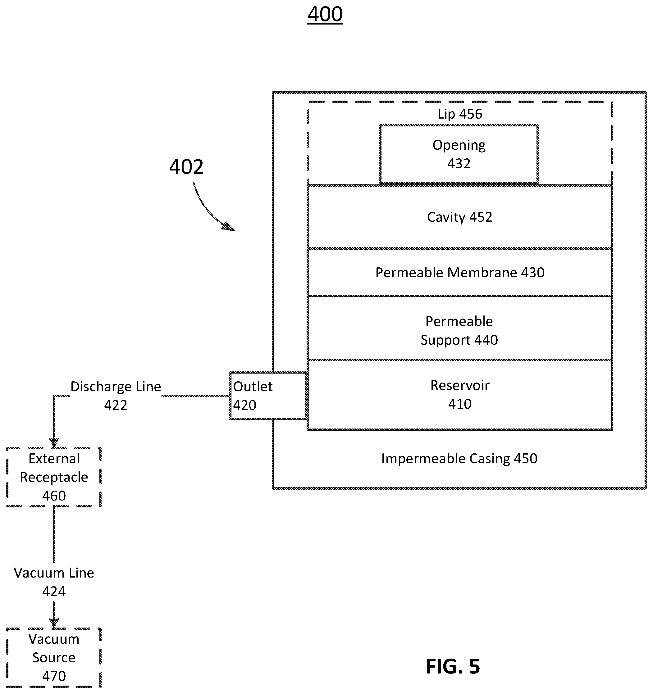
FIG. 5 is a schematic block diagram of a system, according to an embodiment.
FIG. 6 is a top view of an assembly, according to an embodiment.
FIG. 7 is a cross-sectional view of the assembly of FIG. 5 taken along line 7-7 of FIG. 5.
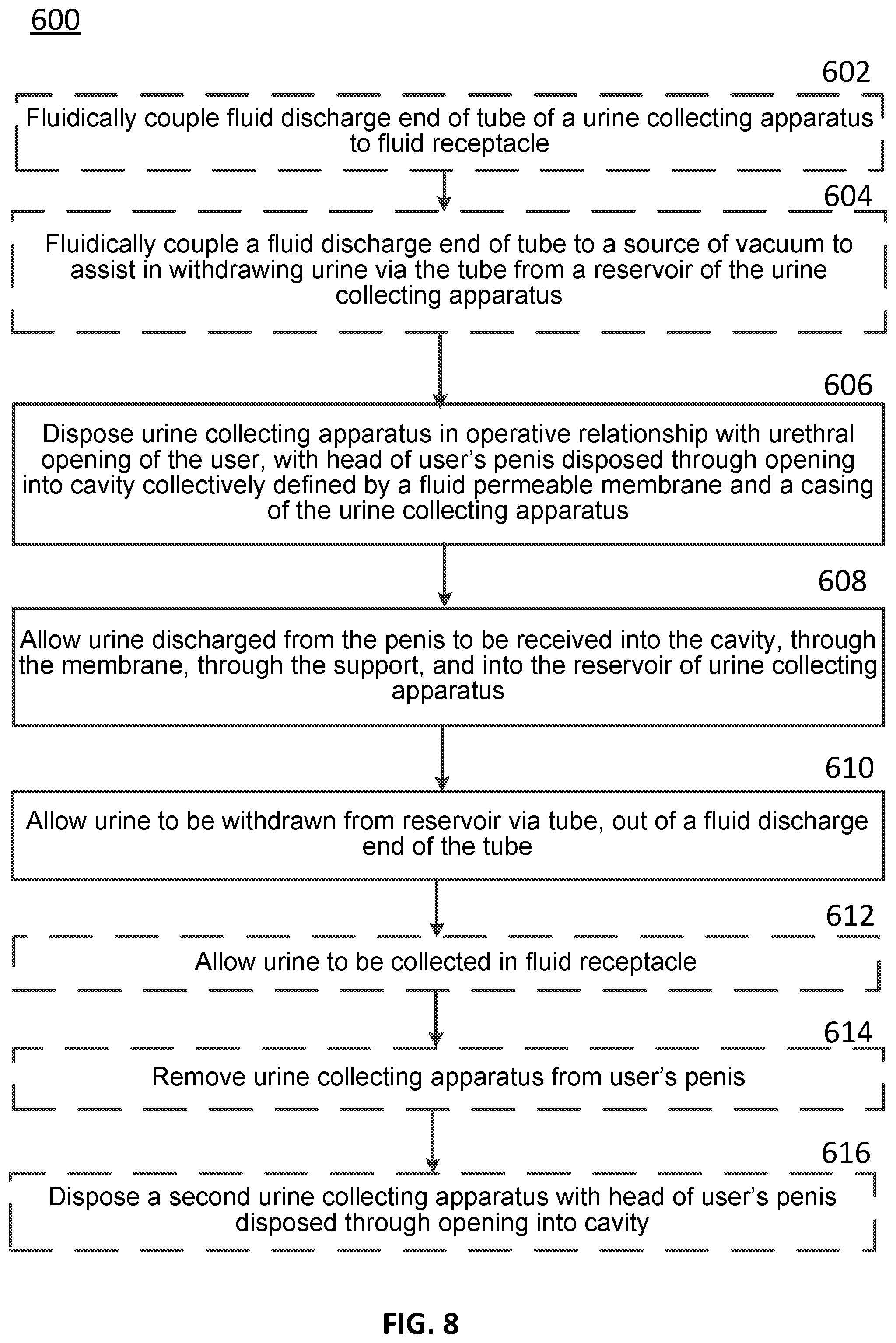
FIG. 8 is a flowchart illustrating a method of using an assembly to collect urine from a user, according to an embodiment.
DETAILED DESCRIPTION
A system is disclosed that is suitable for collecting and transporting urine away from the body of a person or animal, particularly a male. In some embodiments, the disclosed system includes an apparatus that may include a fluid impermeable casing, a fluid permeable support, a fluid permeable membrane, and a tube. The fluid impermeable casing can define an opening, an interior region, and a fluid outlet. The fluid permeable support can define a reservoir. The support can be disposed within the interior region. The fluid permeable membrane can be disposed on the support and cover at least a portion of the support. The fluid permeable membrane can at least partially define a cavity. The tube can have a first end disposed in the elongated reservoir and can extend through the fluid outlet to a second, fluid discharge end. The apparatus is configured to be disposed with a user's penis disposed through the opening and with the urethral opening of the penis disposed within the cavity, to receive urine discharged from the urethral opening through the membrane, the support, and into the reservoir, and to have the received urine withdrawn from the reservoir via the tube and out of the fluid discharge end of the tube.
In some embodiments, a method includes disposing in operative relationship with the urethral opening of a male user, a urine collecting apparatus. The method can include disposing in operative relationship with the urethral opening of a male user a urine collecting apparatus. The urine collecting apparatus can include a fluid impermeable casing, a fluid permeable support, a fluid permeable membrane, and a tube. The fluid impermeable casing can define an opening, an interior region, and a fluid outlet. The fluid permeable support can define a reservoir. The support can be disposed within the interior region. The fluid permeable membrane can be disposed on the support and can cover at least the portion of the support. The fluid permeable membrane can at least partially define a cavity. The tube can have a first end disposed in the elongated reservoir and extending through the fluid outlet to a second, fluid discharge end. The operative relationship can include the user's penis being disposed through the opening in the casing with the urethral opening of the penis disposed within the cavity. Urine discharged from the urethral opening can be allowed to be received through the membrane, the support, and into the reservoir. The received urine can be withdrawn from the reservoir via the tube and out of the fluid discharge end of the tube.
In some embodiments, an apparatus can include a fluid impermeable casing, a fluid permeable support, a fluid permeable membrane, and a tube. The fluid impermeable casing can define an opening, an interior region, and a fluid outlet. The fluid permeable support can be disposed within the interior region and have a first side facing the opening and a second side opposite the first side. The second side and the casing can collectively define a reservoir between the second side and the casing. The fluid permeable membrane can be disposed on the support between the opening and the first side of the support. The fluid permeable membrane and the casing can collectively define a cavity. The tube can have a first end disposed in the reservoir and can extend through the fluid outlet to a second, fluid discharge end. The apparatus can be configured to be disposed with a user's penis disposed through the opening with the urethral opening of the penis disposed within the cavity, to receive urine discharged from the urethral opening through the membrane, the support, and into the reservoir, and to have the received urine withdrawn from the reservoir via the tube and out of the fluid discharge end of the tube.
In some embodiments, a method can include disposing in operative relationship with the urethral opening of a male user a urine collecting apparatus. The urine collecting apparatus can include a fluid impermeable casing, a fluid permeable support, a fluid permeable membrane, and a tube. The fluid impermeable casing can define an opening, an interior region, and a fluid outlet. The fluid permeable support can be disposed within the interior region and have a first side facing the opening and a second side opposite the first side. The second side and the casing can collectively defining a reservoir between the second side and the casing. The fluid permeable membrane can be disposed on the support between the opening and the first side of the support. The fluid permeable membrane and the casing can collectively defining a cavity. The tube can have a first end disposed in the reservoir and can extend through the fluid outlet to a second, fluid discharge end. The operative relationship can include the user's penis being disposed through the opening in the casing with the urethral opening of the penis disposed within the cavity. Urine discharged from the urethral opening can be allowed to be received through the membrane, the support, and into the reservoir. The received urine can be allowed to be withdrawn from the reservoir via the tube and out of the fluid discharge end of the tube.
In some embodiments, a device can be used to so collect urine flowing from the penis of a person or an animal in such a manner that the urine can be readily transported from the device as the urine is being collected. The device can include a chamber assembly in which wicking material is disposed about porous material that is configured to form a chamber in which urine can be collected for transport. The chamber can have a port for receiving a tube so that urine collected within the chamber can be transported from the chamber by being drawn from the chamber when a partial vacuum is applied within the chamber via said received tube. The chamber assembly can be so dimensioned and configured that opposing portions of the assembly can be sufficiently adjacent as to define an opening through the which the head of a penis can be inserted. A layer of impermeable material can be so attached to the chamber assembly as to cover one side of the opening and thereby provide a receptacle for receiving the head of said inserted penis. Urine flowing from said penis can be drawn from the receptacle through the wicking material and the porous material into the chamber when said partial vacuum is applied within the chamber via said tube.
In some embodiments, a device can be used to so collect urine flowing from the penis of a person or an animal in such a manner that the urine can be transported from the device as the urine is being collected. The device can include a flexible layer of porous material, a flexible wicking material disposed on one side of the layer of porous material, and a flexible layer of impermeable material. The flexible layer of impermeable material can be secured to the periphery of the other side of the layer of porous material and so cover the other side of the layer of porous material as to define a chamber between the layer of porous material and the layer of impermeable material, within which chamber urine can be collected for transport. The chamber can have a port for receiving a tube so that urine collected within the chamber can be transported from the chamber by being drawn from the chamber when a partial vacuum is applied within the chamber via said received tube. The combination of the wicking material, the layer of porous material, and the layer of impermeable material can be so dimensioned and configured as to provide a receptacle for receiving the head of a penis. Urine flowing from said penis can be drawn from the receptacle through the wicking material and the porous material into the chamber when said partial vacuum is applied within the chamber via said received tube.
As used in this specification, the singular forms "a," "an" and "the" include plural referents unless the context clearly dictates otherwise. Thus, for example, the term "a member" is intended to mean a single member or a combination of members, "a material" is intended to mean one or more materials, or a combination thereof.
The embodiments described herein can be formed or constructed of one or more biocompatible materials. Examples of suitable biocompatible materials include metals, ceramics, or polymers. Examples of suitable metals include pharmaceutical grade stainless steel, gold, titanium, nickel, iron, platinum, tin, chromium, copper, and/or alloys thereof. Examples of polymers include nylons, polyesters, polycarbonates, polyacrylates, polymers of ethylene-vinyl acetates and other acyl substituted cellulose acetates, non-degradable polyurethanes, polystyrenes, polyvinyl chloride, polyvinyl fluoride, poly(vinyl imidazole), chlorosulphonate polyolefins, polyethylene oxide, polyethylene terephthalate (PET), polytetrafluoroethylene (PTFE), and/or blends and copolymers thereof.
FIG. 1 is a schematic block diagram of a system 100. The system 100 includes an assembly 102. The assembly 102 includes a permeable membrane 130, a permeable support 140, and an impermeable casing 150 (also referred to herein as an "impermeable layer"). The permeable membrane 130 and the permeable support 140 can also be collectively referred to as a "chamber assembly." The permeable support 140 defines a reservoir 110 (also referred to herein as a "chamber"). The assembly 102 also includes an outlet 120 (also referred to herein as a "port") in fluidic communication with the reservoir 110. The permeable support 140 and the permeable membrane 130 can be arranged such that the permeable membrane 130 defines a cavity 152. The impermeable casing 150 defines an opening 132 such that the cavity 152 is accessible from the exterior of the assembly 100. The impermeable casing 150 can direct fluid toward the reservoir 110 and/or reduce and/or prevent fluid from exiting the assembly 102 except via the outlet 120. In some implementations, the assembly 102 can be arranged such that a fluid can flow through the opening 132, into the cavity 152, through the permeable membrane 130, through the permeable support 140, into the reservoir 110, and out of the outlet 120. In some implementations, the assembly 102 can be arranged such that a user's penis can be inserted through the opening 132 such that the user's urethral opening is disposed within the cavity 152 and a fluid can flow from the user's urethral opening, into the cavity 152, through the permeable membrane 130, through the permeable support 140, into the reservoir 110, and out of the outlet 120. In some implementations, the system 100 can include a discharge line 122 (also referred to herein as a "received tube"). The discharge line 122 can be fluidically coupled to an external receptacle 160. The external receptacle 160 can be in fluidic communication with a vacuum source 170 via a vacuum line 124. The discharge line 122 and the vacuum line 124 can both include flexible tubing, such as, for example, flexible plastic tubing.
More specifically, the impermeable casing 150 can define an interior region accessible via the opening 132. The permeable membrane 130 and the permeable support 140 (and thus, the reservoir 110) can be disposed within the interior region of the impermeable casing 150. The impermeable casing 150 can be any suitable shape. For example, in some implementations, the impermeable casing 150 can be bowl-shaped. In some implementations, the impermeable casing 150 can include a bottom surface and at least one sidewall. In some implementations, the at least one sidewall can define the opening 132 such that the opening 132 is opposite the bottom surface of the impermeable casing 150 and the interior region of the impermeable casing 150 is bounded (and collectively defined) by the bottom surface, the sidewall, and the opening 132. In some implementations, the impermeable casing 150 includes a top surface and the top surface defines the opening 132 opposite the bottom surface. In some implementations, the sidewall of the impermeable casing 150 is curved and continuous such that the impermeable casing 150 has a round (e.g., circular or ovalular) perimeter. In some implementations, the impermeable casing 150 can have any suitable shape and/or perimeter, such as the shape of an oblong, a square, or a triangle. In some implementations, the one or more sidewalls can be concave such that the one or more sidewalls can receive at least a portion of the permeable membrane 130 and the permeable support 140 as described in more detail below.
In some implementations, the impermeable casing 150 can be disposed around only a portion of the exterior sides of the permeable membrane 130 and/or the permeable support 140. In some implementations, the impermeable casing 150 can cover all of the exterior sides of the chamber assembly (i.e., the permeable membrane 130 and/or permeable support 140). In some implementations, the impermeable casing 150 can be disposed such that the impermeable casing 150 can wrap around the exterior surface of the permeable membrane 130 and/or the permeable support 140 and cover a portion of the interior side or sides of the chamber assembly (i.e., the permeable membrane 130 and/or the permeable support 140). In some implementations, the permeable membrane 130 and the permeable support 140 can be arranged to define a passageway with open ends (e.g., as a ring), and the impermeable casing 150 can be applied to one end and a side of the chamber assembly (i.e., the permeable membrane 130 and the permeable support 140) such that a cavity 152 is defined with the open end and the closed end. In some implementations, the chamber assembly can define the opening 132 rather than the impermeable casing 150. In some implementations, the portion of the impermeable casing 150 closing one end of the cavity 152 and partially defining the cavity 152 can have any suitable shape such that a portion or all of the head of a user's penis can be disposed within the cavity 152. For example, the portion of the impermeable casing 150 closing one end of the cavity 152 can be curved, convex, or flat.
In some implementations, the impermeable casing 150 can be attached to the chamber assembly (i.e., the permeable membrane 130 and the permeable support 140) via an adhesive. In some implementations, the impermeable casing 150 can be attached to the chamber assembly via any suitable retention mechanism, such as, for example, retainer clips or other fasteners. In some implementations, the impermeable casing 150 can be preshaped and the chamber assembly can be inserted into the impermeable casing 150 and retained in a particular shape by the impermeable casing 150. In some implementations, the impermeable casing 150 can be formed by, for example, elongate strips of adhesive tape such that the impermeable casing 150 can maintain the chamber assembly in the configuration defining the cavity 152.
The impermeable layer 150 can be impermeable to fluid, such as, for example, urine. In some implementations, the impermeable layer 150 can have a fluid transportation function and can assist in directing fluid towards the reservoir 110 and/or through the outlet 120 of the reservoir 110. In some implementations, the impermeable layer 150 can be formed as an integral, unitary structure. In other implementations, the impermeable layer 150 can be a multi-piece structure. The impermeable layer 150 can be a pre-molded (e.g., injection or blow molded) component. Alternatively, the impermeable layer 150 can be formed of a material, such as elongate strips of an adhesive tape, wrapped around at least a portion of the reservoir 110, a portion of the permeable support 140, and/or a portion of the permeable membrane 130. In some embodiments, the impermeable layer 150 can be formed of cardboard, pressed paper, and/or coated paper. In some embodiments, the impermeable layer 150 can be flexible.
The permeable membrane 130 can be formed of a material that has permeable properties with respect to liquids such as urine. The permeable properties can be wicking, capillary action, diffusion, or other similar properties or processes, and are referred to herein as "permeable" and/or "wicking." The permeable membrane 130 can have a high absorptive rate and a high permeation rate such that urine can be rapidly absorbed by the permeable membrane 130 and/or transported through the permeable membrane 130. In some implementations, the permeable membrane 130 can be flexible. In some implementations, the permeable membrane 130 can be a ribbed knit fabric. In some implementations, the permeable membrane 130 can be shaped as a tubular sleeve such that the permeable membrane 130 can be disposed around the permeable support 140. In some implementations, the permeable membrane 130 can include and/or have the moisture-wicking characteristic of gauze, felt, terrycloth, thick tissue paper, and/or a paper towel. In some implementations, the permeable membrane 130 can be soft and/or minimally abrasive such that the permeable membrane 130 does not irritate the skin of the user. The permeable membrane 130 can be configured to wick fluid away from the urethral opening and/or the skin of the user such that the dampness of the skin of the user is lessened and infections are prevented. Additionally, the wicking properties of the permeable membrane 130 can help prevent urine from leaking or flowing beyond the assembly (e.g., out of opening 132) onto, for example, a bed. In some implementations, the permeable membrane 130 can be formed of fine denier polyester fibers coated with a thermoplastic water-based binder system. The tensile strength can be, for example, about 45 lbs/inch.sup.2 (measured using an Instron test method). The weight of a permeable membrane can be, for example, about 12 grams (measured using the Mettler Gram Scale). The thickness per ten permeable membranes can be, for example, about 2.5'' (measured using the Gustin-Bacon/Measure-Matic).
The permeable support 140 can be positioned relative to the permeable membrane 130 such that the permeable support 140 maintains the permeable membrane 130 in a particular shape and allows for fluid, such as, for example, urine, to flow through the permeable membrane 130, through the permeable support 140, and into the reservoir 110. In some implementations, the permeable support 140 can be ring-shaped such that, when disposed within the impermeable casing 150, the cavity 152 is defined in the center of the ring-shaped permeable support 140. Said another way, an outer surface of the permeable support 140 on the inner portion of the "ring" can define the cavity 152. When the permeable membrane 130 is disposed on the permeable support 140, the permeable membrane 130 can define a portion of the boundaries of the cavity 152. When the permeable support 140 and the permeable membrane 130 are disposed within the impermeable casing 150, the cavity 152 can be aligned with the opening 132 of the impermeable casing 150. The reservoir 110 can be defined within or by the permeable support 140 such that the reservoir 110 is an elongated, ring-shaped reservoir.
In some implementations, the permeable support 140 can be shaped and/or formed as a complete or continuous ring or circle. In some implementations, the permeable support 140 can be shaped and/or formed as a partial circle and/or in a discontinuous C-shape with spaced ends. In some implementations, the permeable support 140 can be U-shaped. In some implementations, the chamber assembly can be dimensioned and configured such that opposing end portions of the chamber assembly are sufficiently adjacent or proximate as to define an opening through which the head of a penis can be inserted. In some implementations, the permeable support 140 can be formed of a bendable tube having two ends. The bendable tube can be arranged such that the two ends meet (e.g., forming a C-shape) and the permeable support 140 can be secured such that the permeable support 140 has a substantially circular shape. In some implementations, the outlet or port 120 can be positioned at the intersection of the two ends and in fluid communication with the elongated ring-shaped reservoir 110 defined by the permeable support 140. The discharge line 122 can be inserted through the outlet 120 (and thus through the impermeable casing 150 and the permeable support 140) and into fluid communication with the reservoir 110.
In some implementations, the permeable support 140 can be formed as an elongated tube such that the reservoir 110 extends through a portion or through the entire length of the elongated tube. The permeable support 140 can then be arranged and/or bent to form a ring such that the permeable support 140 defines the cavity 152 in the center of the ring. In some implementations, the inner diameter or other dimensions of the permeable support 140 can be sized such that the cavity 152 can receive a penis of a user such that a head of the penis can be partially or fully disposed within the cavity 152 when the penis is disposed within the opening 132 of the impermeable casing 150. Said another way, the shaft of the penis can be disposed within the opening 132 and the head of the penis can be fully disposed within the cavity 152, or the urethral opening of the head of the penis can be disposed within the cavity 152 and the head can be partially disposed within the cavity 152 and partially outside the cavity 152, with the opening 132 surrounding a portion of the head. In some implementations, the cavity 152 can be dimensioned to receive a head of a penis of a user such that urine can be received from the urethral opening of the penis within the cavity 152, by the permeable membrane 130, and/or by the permeable support 140 without urine splashing out of the opening 132.
In some implementations, the permeable support 140 can be configured to maintain the permeable membrane 130 against the skin of a penis of a user and/or near a urethral opening of a user. For example, the permeable support 140 can be shaped and sized such that the cavity 152 is slightly larger than a head or tip of a penis of a user. The permeable support 140 can include a portion having a curved or convex shape in contact with the permeable membrane 130 such that the permeable membrane 130 is also curved or convex. The permeable support 140 can support the permeable membrane 130 such that the permeable membrane 130 can rest against the skin of the head or tip of the penis with the urethral opening directed toward a bottom surface of the impermeable casing 150, and thus creating a comfortable and at least partially enclosed interface for engagement with the area of the body (e.g., the head and/or neck of a penis of a user) near the urethral opening.
In some implementations, the permeable support 140 can be made of a rigid plastic. In some implementations, the permeable support 140 can have any suitable shape and be formed of any suitable material. For example, the permeable support 140 can be flexible. Additionally, the permeable support 140 can be formed of aluminum, a composite of plastic and aluminum, some other metal and/or a composite of plastic and another metal. In some implementations, the permeable support 140 can be formed of a natural material, such as, for example, plant fibers (e.g., Greener Clean manufactured by 3M.RTM.). The natural material can include openings that allow fluid to flow through the natural material. In some embodiments, the permeable support 140 can be cylindrical and can define a lumen. In some embodiments, the permeable support 140 can be formed of perforated coated paper, such as tubular waxed paper.
The permeable support 140 can define one or more openings (e.g., an array of openings) to allow for fluid flow from the permeable membrane 130 to the reservoir 110. In some implementations, the permeable support 140 can be formed as a curved tube or a curved cylinder with one or more openings. In some implementations, the permeable support 140 can include membrane supports (e.g., struts) extending across an opening such that the opening is divided into an array of distinct slot-shaped openings. The membrane supports can be used to support the permeable membrane 130. For example, the membrane supports can maintain the shape of the permeable membrane 130 against the skin of a penis of a user and/or near a urethral opening of a user such that urine flowing from the urethral opening contacts and travels through the permeable membrane 130. In some implementations, the permeable support 140 can define several openings having a variety of shapes, such as a plurality of round openings. In some implementations, the permeable support 140 can be formed as a curved or ring-shaped cylinder of spun plastic (e.g., non-woven permeable nylon and polyester webbing) such that the permeable support 140 can have many openings. For example, a rectangular portion of spun plastic can be folded or rolled into a cylinder shape and then curved into a ring or U-shape for use in the assembly 102. In some implementations, the permeable support 140 can be formed of a porous material. For example, the permeable support 140 can be a porous glass ring-shaped tubular container defining frits. In other implementations, the permeable support 140 can define an opening in a sidewall of the permeable support 140 and the sidewall can be covered by a mesh screen defining many smaller openings. In some embodiments, the reservoir 110 can include any spaces and/or openings defined within the permeable support 140 (e.g., spaces within porous material or defined within spun plastic material).
The reservoir 110 can be any suitable shape and/or have any diameter (or other dimension) suitable for receiving and transporting urine during use of the system 100. In some implementations, the reservoir 110 can be sized such that the reservoir 110 is capable of collecting and temporarily holding a large or small amount of urine until the urine can be removed from the reservoir via the outlet 120. For example, the reservoir 110 can be sized such that the reservoir 110 is configured to hold a small amount of urine as may be released due to incontinence. In some implementations, the reservoir 110 can be sized such that the reservoir 110 is configured to hold a large amount of urine as may be released during voiding of a full bladder. In some implementations, the reservoir 110 can be sized such that the reservoir is configured to collect and hold a small or large amount of urine while the urine is simultaneously removed via, for example, gravity and/or a pump, such as the vacuum source 170. Said another way, the reservoir 110 can function as a sump and be sized such that the reservoir 110 can form a portion of a passageway for urine from the permeable membrane 130, through the permeable support 140, through the reservoir 110, and out of the outlet 120. In a condition where the flow rate of urine into the assembly 102 via the permeable membrane 130 is greater than the flow rate of urine through the discharge line 122, a temporary backup of urine may occur in the reservoir 110. Thus, the reservoir 110 can be sized to contain a volume of fluid that may temporarily accumulate due to the difference in flow rates into and out of the assembly 102. Although the outlet 120 is shown as extending from the side of the reservoir 110, in some implementations, the outlet 120 can extend from the bottom of the reservoir 110.
In some embodiments, the assembly 102 can optionally include a cushion assembly 180. The cushion assembly 180 can include a membrane layer 182 and a support layer 184 (also referred to herein as a "bed of porous material"). The membrane layer 182 can be formed of the same or a similar material as the permeable membrane 130 and can have the same or similar properties as the permeable membrane 130. For example, the membrane layer 182 can be configured to wick fluid (e.g., urine) away from a urethral opening of a user when a urethral opening of a user is position near or in contact with the membrane layer 182. The membrane layer 182 can also be permeable such that fluid (e.g., urine) can flow through the membrane layer 182 and to the permeable membrane 130 and/or the permeable support 140, into the reservoir 110, and through the outlet 120. The support layer 184 can be formed of the same or a similar material as the permeable support 140 and can have the same or similar properties as the permeable support 140. For example, the support layer 184 can be configured to maintain the membrane layer 182 near or in contact with the head of a user's penis when the head of the user's penis is disposed within the cavity 152 of the assembly 102. The support layer 184 can also be permeable such that fluid (e.g., urine) can flow through the membrane layer 182, through the support layer 184, and to the permeable membrane 130 and/or the permeable support 140, into the reservoir 110, and through the outlet 120. The cushion assembly 180 can be arranged within the impermeable casing 150 such that the cushion assembly 180 forms a boundary of the cavity 152 (e.g., the bottom of the cavity 152). The cushion assembly 180 can be positioned along a bottom surface of the impermeable casing 150 such that a user's penis can be placed in contact with the cushion assembly 180 and/or such that urine flowing from a user's urethral opening into the cavity 152 can flow into the cushion assembly 180 thereby reducing splashing. In some implementations, the cushion assembly 180 (and specifically the membrane layer 182) can be disposed within the impermeable casing 150 such that the cushion assembly 180 contacts the permeable membrane 130.
The external receptacle 160, via the discharge line 122, can collect fluid exiting the reservoir 110 through the outlet 120. The external receptacle 160 can be a sealed container. In some implementations, the external receptacle 160 can be disposable. In some implementations, the external receptacle 160 can be configured to be sterilized and reused.
In some implementations, gravity can cause fluid within the reservoir 110 to follow a flow path (i.e., the fluid flow path including the outlet 120 and the discharge line 122) from the reservoir 110 to the external receptacle 160. In some implementations, the vacuum source 170 can assist and/or provide the pressure differential needed to draw fluid voided from the urethral opening of a user into the permeable support 140, into the reservoir 110, and from the reservoir 110 into the external receptacle 160. The vacuum source 170 can be fluidically coupled to the external receptacle 160 via a vacuum line 124 such that gaseous fluid is drawn from the external receptacle 160 via the vacuum line 124. As a result of the decrease in pressure within the external receptacle 160 caused by the drawing of gaseous fluid out of the external receptacle 160, liquid and/or gaseous fluid can be drawn from the reservoir 110, through the outlet 120, through the discharge line 122, and into the external receptacle 160. In some implementations, the vacuum source 170 can apply sufficient suction to capture all or substantially all of the urine voided by a user in a variety of positions (e.g., when a male user is lying on his side or back).
The vacuum source 170 can have a sufficiently high vacuum strength and air volume transport rate such that rapid air and liquid aspiration is maintained over a portion of or the entire permeable membrane 130. In some implementations, the one or more openings of the permeable support 140 are distributed over an area that is slightly larger than the area of the permeable membrane 130 that is configured to be wetted by urine flow in operation. Thus, the partial vacuum created by the vacuum source 170 in combination with the one or more openings of the permeable support 140 and the permeable membrane 130 can draw the urine contacting the permeable membrane 130 into the assembly 102 and, specifically, into the reservoir 110. In some implementations, however, the one or more openings of the permeable support 140 should not be distributed over too large of an area of the permeable support 140 because the partial vacuum strength may be reduced, thereby reducing the urine collection rate and the efficiency of the system 100.
In some implementations, the vacuum source 170 can be a pump that is readily available, inexpensive, relatively quiet, and/or configured to run continuously. For example, the vacuum source 170 can be an aquarium aerator pump. The vacuum line 124 can be attached to the intake port of the aquarium aerator pump (rather than the exhaust port of the aerator) such that gaseous fluid is drawn into the aquarium aerator pump from the external receptacle 160 via the vacuum line 124. In some implementations, the necessary static vacuum of the system 100 is about 3-10 feet of water (10%-30% of one atmosphere; 80-250 mm Hg) with a free-flow rate of about 10-100 cubic centimeters per second. In some implementations, the necessary static vacuum of the system 100 is higher or lower depending on the size of the user and the expected rate of urine flow from the user and/or through the system 100. In some implementations, the discharge line 122 can be about 0.25'' in diameter and the vacuum source 170 can be configured to cause about 500 cubic centimeters of urine to flow through the discharge line 122 to the external receptacle 160 over the duration of a typical urination event for a user, which may typically range from 10 to 20 seconds but may be shorter or longer, e.g., 5 to 90 seconds. In some implementations, the vacuum source 170 can include a wall-mounted vacuum system, such as is found in hospitals. In some implementations, a wall-mounted vacuum system can be configured to apply a vacuum of, for example, about 20 mm Hg to about 40 mm Hg. In some implementations, the vacuum source 170 can be powered by electrical AC or DC power. For example, in mobile applications when the user is away from an AC power source, such as when the user is using the system 100 during transportation via a wheel chair or motor vehicle, the vacuum source 170 can be powered by DC power.
In some implementations, urine collected by any of the systems and/or assemblies described herein can be sampled for analysis using urine strips. Urine test strips can be used to test a variety of health measures. Urine test strips can be configured to change color in response to being wetted with urine to indicate a particular measurement (i.e., the colors can correspond to known measurement scales). In some implementations, a urine test strip (not shown) can be inserted into the discharge line 122 such that urine flowing from the outlet 120 to the external receptacle 160 contacts the urine test strip. The discharge line 122 can be transparent such that data on the urine test strip can be read through a wall of the discharge line 122. In some implementations, the urine test strip can be disposed within the external receptacle 160 such that urine flowing into the external receptacle 160 contacts the urine test strip. The external receptacle 160 can be at least partially transparent such that the urine test strip can be read through a wall of the external receptacle 160.
In some implementations, a camera, such as a camera built into a portable communication device (e.g., a smartphone, an iPhone, or the like) can be used to read the data on the urine test strip. The camera can capture an image of the test strip and the image can be processed using, for example, a smartphone application. The data read from the urine test strip can be sent to a clinician for analysis and/or sent to a cloud-based address for physician access.
In some implementations, the system 100 can include a scale (not shown). For example, the scale can be disposed underneath the external receptacle 160 such that the scale is configured to measure the weight of fluid (e.g., urine) in the external receptacle 160. The data indicating the weight of the fluid that has been delivered to the external receptacle 160 via the discharge line 122 can be measured at different time intervals and processed to determine how much urine, for example, has been voided by a user of the system 100.
Although described as being intended for use by an adult male, in some implementations the system 100 can be used in adult, pediatric, male, female, and veterinary applications for animals of different species and sizes. In female applications, the assembly 102 can be placed between the legs or labia of the user and held snugly against the external urethra by the pressure of friction from the user's body, by the pressure of the legs or by such means as an undergarment, elastic strips, and/or adhesive tape. In male applications, the assembly 102 can be placed such that a penis of a user is disposed within the assembly 102 (e.g., within the cavity 152 formed within the assembly 102). A male user can use the assembly 102 in any suitable position, such as, for example, while lying on his back, lying on his side, sitting, or standing. In some implementations, the head of the penis of the male user can be placed in contact with the permeable membrane 130 and/or the membrane layer 182 during urination. In some implementations, the head of the penis of the male user can be disposed at least partially within the cavity 452, but not placed in contact with the permeable membrane 430 and/or the membrane layer 182 during urination.
FIG. 2 is a top view of an assembly 202. FIG. 3 is a cross-sectional view of the assembly 202 taken along line 3-3 in FIG. 2. The assembly 202 includes a permeable membrane 230, a permeable support 240, and a cushion assembly 280. The permeable membrane 230 and the permeable support 240 can also be collectively referred to as a "chamber assembly." The permeable membrane 230, the permeable support 240, and the cushion assembly 280 are disposed within an impermeable casing 250 (also referred to herein as an "impermeable layer"). The permeable membrane 230, the permeable support 240, the cushion assembly 280, and the impermeable casing 250 can be the same or similar in structure and/or function to the permeable membrane 130, the permeable support 140, the cushion assembly 180, and the impermeable casing 150 described above with reference to the system 100. For example, the permeable support 240 defines a reservoir 210 (also referred to herein as a "channel"). The impermeable casing 250 defines an opening 232 (also referred to herein as a "port"). The assembly 202 also includes an outlet 220 in fluidic communication with the reservoir 210.
The permeable support 240 and the permeable membrane 230 can be arranged such that the permeable support 240 and/or the permeable membrane 230 collectively define a cavity 252 within the permeable membrane 230. The impermeable casing 250 can direct fluid toward the reservoir 210 and/or reduce and/or prevent fluid from exiting the assembly 202 except via the outlet 220. In some implementations, the assembly 202 can be arranged such that a fluid can flow through the opening 232, into the cavity 252, through the permeable membrane 230, through the permeable support 240, into the reservoir 210, and out of the outlet 220. In some implementations, the assembly 202 can be arranged such that a user's penis can be inserted through the opening 232 such that the user's urethral opening is disposed within the cavity 252 and a fluid can flow from the user's urethral opening, into the cavity 252, through the permeable membrane 230, through the permeable support 240, into the reservoir 210, and out of the outlet 220. A discharge line 222 (e.g., a tube) (also referred to herein as a "received tube") can extend through the outlet 220. A first end (not shown) of the discharge line 222 can be positioned within the reservoir 210, and the discharge line 222 can extend through the permeable support 240, the permeable membrane 230, and the impermeable casing 250 such that fluid in the reservoir 210 can be transported away from the assembly 202 via the discharge line 222. A second end of the discharge line 222 can be fluidically coupled to an external receptacle (e.g., external receptacle 160). The external receptacle can be in fluidic communication with a vacuum source (e.g., vacuum source 170) via a vacuum line (e.g., vacuum line 124). The discharge line 222 and the vacuum line can both include flexible tubing, such as, for example, flexible plastic tubing.
More specifically, the impermeable casing 250 can define an interior region accessible via the opening 232. The permeable membrane 230 and the permeable support 240 (and thus, the reservoir 210) can be disposed within the interior region of the impermeable casing 250. The impermeable casing 250 can be any suitable shape. For example, in some implementations, the impermeable casing 250 can be bowl-shaped. As shown in FIG. 3, the impermeable casing 250 can include a bottom surface and a sidewall. The sidewall can define the opening 232 such that the opening 232 is opposite the bottom surface of the impermeable casing 250 and the interior region of the impermeable casing 250 is bounded (and collectively defined) by the bottom surface, the sidewall, and the opening 232. The sidewall of the impermeable casing 250 can be curved and continuous such that the impermeable casing 250 has a round (e.g., circular or ovalular) perimeter. The sidewall can be concave such that the one or more sidewalls can receive at least a portion of the permeable membrane 230 and the permeable support 240 as shown in FIG. 3.
The impermeable layer 250 can be impermeable to fluid, such as, for example, urine. In some implementations, the impermeable layer 250 can have a fluid transportation function and can assist in directing fluid towards the reservoir 210 and/or through the outlet 220 of the reservoir 210. In some implementations, the impermeable layer 250 can be formed as an integral, unitary structure. In other implementations, the impermeable layer 250 can be a multi-piece structure. The impermeable layer 250 can be a pre-molded (e.g., injection or blow molded) component. Alternatively, the impermeable layer 250 can be formed of a material, such as elongate strips of an adhesive tape, wrapped around at least a portion of the reservoir 210, a portion of the permeable support 240, and/or a portion of the permeable membrane 230. In some embodiments, the impermeable layer 250 can be formed of cardboard, pressed paper, and/or coated paper. In some embodiments, the impermeable layer 250 can be flexible.
The permeable membrane 230 can be formed of a material that has permeable properties with respect to liquids such as urine. The permeable properties can be wicking, capillary action, diffusion, or other similar properties or processes, and are referred to herein as "permeable" and/or "wicking." The permeable membrane 230 can have a high absorptive rate and a high permeation rate such that urine can be rapidly absorbed by the permeable membrane 230 and/or transported through the permeable membrane 230. In some implementations, the permeable membrane 230 can be flexible. In some implementations, the permeable membrane 230 can be a ribbed knit fabric. In some implementations, the permeable membrane 230 can be shaped as a tubular sleeve such that the permeable membrane 230 can be disposed around the permeable support 240. In some implementations, the permeable membrane 230 can include and/or have the moisture-wicking characteristic of gauze, felt, terrycloth, thick tissue paper, and/or a paper towel. In some implementations, the permeable membrane 230 can be soft and/or minimally abrasive such that the permeable membrane 230 does not irritate the skin of the user. The permeable membrane 230 can be configured to wick fluid away from the urethral opening and/or the skin of the user such that the dampness of the skin of the user is lessened and infections are prevented. Additionally, the wicking properties of the permeable membrane 230 can help prevent urine from leaking or flowing beyond the assembly (e.g., out of opening 232) onto, for example, a bed. In some implementations, the permeable membrane 230 can be formed of fine denier polyester fibers coated with a thermoplastic water-based binder system. The tensile strength can be, for example, about 45 lbs/inch.sup.2 (measured using an Instron test method). The weight of a permeable membrane can be, for example, about 12 grams (measured using the Mettler Gram Scale). The thickness per ten permeable membranes can be, for example, about 2.5'' (measured using the Gustin-Bacon/Measure-Matic).
The permeable support 240 can be positioned relative to the permeable membrane 230 such that the permeable support 240 maintains the permeable membrane 230 in a particular shape and allows for fluid, such as, for example, urine, to flow through the permeable membrane 230, through the permeable support 240, and into the reservoir 210. As shown in FIG. 2, the permeable support 240 can be ring-shaped such that, when the permeable membrane 230 is disposed on the permeable support 240 and the permeable support 240 is disposed within the impermeable casing 250, the cavity 252 is defined in the center of the ring-shaped permeable support 240 and permeable membrane 230. Said another way, an outer surface of the permeable membrane 230 on the inner portion of the "ring" can define the cavity 252. As shown in FIGS. 2 and 3, the cavity 252 can be aligned with the opening 232 of the impermeable casing 250. The reservoir 210 can be defined within the permeable support 240 such that the reservoir 210 is an elongated, ring-shaped reservoir.
In some implementations, the permeable support 240 can be shaped and/or formed as a complete or continuous ring or circle. In some implementations, the permeable support 240 can be shaped and/or formed as a partial circle. In some implementations, the chamber assembly can be dimensioned and configured such that opposing end portions of the chamber assembly are sufficiently adjacent or proximate as to define an opening through which the head of a penis can be inserted. In some implementations, the permeable support 240 can be formed of a bendable tube having two ends. The bendable tube can be arranged such that the two ends meet (e.g., forming a C-shape) and the permeable support 240 can be secured such that the permeable support 240 has a substantially circular shape. In some implementations, the outlet or port 220 can be positioned at the intersection of the two ends and in fluid communication with the elongated ring-shaped reservoir 210 defined by the permeable support 240. The discharge line 222 can be inserted through the outlet 220 (and thus through the impermeable casing 250 and the permeable support 240) and into fluid communication with the reservoir 210.
In some implementations, the permeable support 240 can be formed as an elongated tube such that the reservoir 210 extends through a portion or through the entire length of the elongated tube. The permeable support 240 can then be arranged and/or bent to form a ring such that the permeable support 240 defines the cavity 252 in the center of the ring. In some implementations, the inner diameter or other dimensions of the permeable support 240 can be sized such that the cavity 252 can receive a penis of a user such that a head of the penis can be partially or fully disposed within the cavity when the penis is disposed within the opening 232 of the impermeable casing 250. Said another way, the shaft of the penis can be disposed within the opening 232 and the head of the penis can be fully disposed within the cavity 252, or the urethral opening of the head of the penis can be disposed within the cavity 252 and the head can be partially disposed within the cavity 252 and partially outside the cavity 252, with the opening 232 surrounding a portion of the head. In some implementations, the cavity 252 can be dimensioned to receive a head of a penis of a user such that urine can be received from the urethral opening of the penis within the cavity 252, by the permeable membrane 230, and/or by the permeable support 240 without urine splashing out of the opening 232.
In some implementations, the permeable support 240 can be configured to maintain the permeable membrane 230 against the skin of a penis of a user and/or near a urethral opening of a user. For example, the permeable support 240 can be shaped and sized such that the cavity 252 is slightly larger than a head or tip of a penis of a user. The permeable support 240 can include a portion having a curved or convex shape in contact with the permeable membrane 230 such that the permeable membrane 230 is also curved or convex. The permeable support 240 can support the permeable membrane 230 such that the permeable membrane 230 can rest against the skin of the head or tip of the penis with the urethral opening directed toward a bottom surface of the impermeable casing 250, and thus creating a comfortable and at least partially enclosed interface for engagement with the area of the body (e.g., the head and/or neck of a penis of a user) near the urethral opening.
In some implementations, the permeable support 240 can be made of a rigid plastic. In some implementations, the permeable support 240 can have any suitable shape and be formed of any suitable material. For example, the permeable support 240 can be flexible. Additionally, the permeable support 240 can be formed of aluminum, a composite of plastic and aluminum, some other metal and/or a composite of plastic and another metal. In some implementations, the permeable support 240 can be formed of a natural material, such as, for example, plant fibers (e.g., Greener Clean manufactured by 3M.RTM.). The natural material can include openings that allow fluid to flow through the natural material. In some embodiments, the permeable support 240 can be cylindrical and can define a lumen. In some embodiments, the permeable support 240 can be formed of perforated coated paper, such as tubular waxed paper.
The permeable support 240 can define one or more openings (e.g., an array of openings) to allow for fluid flow from the permeable membrane 230 to the reservoir 210. In some implementations, the permeable support 240 can be formed as a curved tube or a curved cylinder with one or more openings. In some implementations, the permeable support 240 can include membrane supports (e.g., struts) extending across an opening such that the opening is divided into an array of distinct slot-shaped openings. The membrane supports can be used to support the permeable membrane 230. For example, the membrane supports can maintain the shape of the permeable membrane 230 against the skin of a penis of a user and/or near a urethral opening of a user such that urine flowing from the urethral opening contacts and travels through the permeable membrane 230. In some implementations, the permeable support 240 can define several openings having a variety of shapes, such as a plurality of round openings. In some implementations, the permeable support 240 can be formed as a curved or ring-shaped cylinder of spun plastic (e.g., non-woven permeable nylon and polyester webbing) such that the permeable support 240 can have many openings. For example, a rectangular portion of spun plastic can be folded or rolled into a cylinder shape and then curved into a ring for use in the assembly 202. In some implementations, the permeable support 240 can be formed of a porous material. For example, the permeable support 240 can be a porous glass ring-shaped tubular container defining frits. In other implementations, the permeable support 240 can define an opening in a sidewall of the permeable support 240 and the sidewall can be covered by a mesh screen defining many smaller openings. In some embodiments, the reservoir 210 can include any spaces and/or openings defined within the permeable support 240 (e.g., spaces within porous material or defined within spun plastic material).
The reservoir 210 can be any suitable shape and/or have any diameter (or other dimension) suitable for receiving and transporting urine during use of a system including the assembly 202. In some implementations, the reservoir 210 can be sized such that the reservoir 210 is capable of collecting and temporarily holding a large or small amount of urine until the urine can be removed from the reservoir via the outlet 220. For example, the reservoir 210 can be sized such that the reservoir 210 is configured to hold a small amount of urine as may be released due to incontinence. In some implementations, the reservoir 210 can be sized such that the reservoir 210 is configured to hold a large amount of urine as may be released during voiding of a full bladder. In some implementations, the reservoir 210 can be sized such that the reservoir is configured to collect and hold a small or large amount of urine while the urine is simultaneously removed via, for example, gravity and/or a pump, such as the vacuum source 270. Said another way, the reservoir 210 can function as a sump and be sized such that the reservoir 210 can form a portion of a passageway for urine from the permeable membrane 230, through the permeable support 240, through the reservoir 210, and out of the outlet 220. In a condition where the flow rate of urine into the assembly 202 via the permeable membrane 230 is greater than the flow rate of urine through the discharge line 222, a temporary backup of urine may occur in the reservoir 210. Thus, the reservoir 210 can be sized to contain a volume of fluid that may temporarily accumulate due to the difference in flow rates into and out of the assembly 202.
Although the outlet 220 is shown as extending from the side of the reservoir 210, in some implementations, the outlet 220 can extend from the bottom of the reservoir 210.
The cushion assembly 280 can include a membrane layer 282 and a support layer 284 (also referred to herein as a "bed of porous material"). The membrane layer 282 can be formed of the same or a similar material as the permeable membrane 230 and can have the same or similar properties as the permeable membrane 230. For example, the membrane layer 282 can be configured to wick fluid (e.g., urine) away from a urethral opening of a user when a urethral opening of a user is position near or in contact with the membrane layer 282. The membrane layer 282 can also be permeable such that fluid (e.g., urine) can flow through the membrane layer 282 and to the permeable membrane 230 and/or the permeable support 240, into the reservoir 210, and through the outlet 220. The support layer 284 can be formed of the same or a similar material as the permeable support 240 and can have the same or similar properties as the permeable support 240. For example, the support layer 284 can be configured to maintain the membrane layer 282 near or in contact with the head of a user's penis when the head of the user's penis is disposed within the cavity 252 of the assembly 202. The support layer 284 can also be permeable such that fluid (e.g., urine) can flow through the membrane layer 282, through the support layer 284, and to the permeable membrane 230 and/or the permeable support 240, into the reservoir 210, and through the outlet 220. The cushion assembly 280 can be arranged within the impermeable casing 250 such that the cushion assembly 280 forms a boundary of the cavity 252 (e.g., the bottom of the cavity 252). The cushion assembly 280 can be positioned along a bottom surface of the impermeable casing 250 such that a user's penis can be placed in contact with the cushion assembly 280 and/or such that urine flowing from a user's urethral opening into the cavity 252 can flow into the cushion assembly 280 thereby reducing splashing. In some implementations, the cushion assembly 280 (and specifically the membrane layer 282) can be disposed within the impermeable casing 250 such that the cushion assembly 280 contacts the permeable membrane 230.
FIG. 4 is a flowchart illustrating a method of using an assembly to collect urine from a user, according to an embodiment. The method 300 optionally includes, at 302, fluidically coupling a discharge end of a tube of a urine collecting apparatus to a fluid receptacle. The method 300 optionally further includes, at 304, fluidically coupling the discharge end of the tube of the urine collecting apparatus to a source of vacuum.
The method 300 further includes, at 306, disposing the urine collecting apparatus in operative relationship with the urethral opening of the user, with a head of a penis of a male user (e.g. human or animal) disposed through an opening and into a cavity at least partially defined by a membrane of the urine collecting apparatus. The urine collecting apparatus can be the same or similar in structure and/or function to any of the urine collecting apparatus described herein, such as, for example, the assembly 102 in FIG. 1 and/or the assembly 202 in FIG. 2. For example, the urine collecting apparatus can include a fluid impermeable casing, a fluid permeable support, a fluid permeable membrane, and a tube. The fluid impermeable casing can define an opening, an interior region, and a fluid outlet. The fluid permeable support can define a reservoir. The fluid permeable support can also be disposed within the interior region of the fluid impermeable casing. The fluid permeable membrane can be disposed on the support and cover at least a portion of the support. The fluid permeable membrane can at least partially define a cavity aligned with the opening defined in the fluid impermeable casing. The tube can have a first end disposed in the elongated reservoir and extend through the fluid outlet to a second, fluid discharge end. The assembly can be arranged such that a fluid can flow into the cavity from the urethral opening of the user's penis, flow through the fluid permeable membrane and the fluid permeable support, collect in the reservoir, and flow out of the outlet.
The method 300 also includes, at 308, allowing urine discharged from the penis to be received into the cavity, through the membrane, through the support, and into the reservoir.
The method 300 also includes, at 310, allowing the received urine to be withdrawn from the reservoir via the tube and out of the fluid discharge end of the tube.
The method 300 optionally includes, at 312, allowing the withdrawn urine to be collected in the fluid receptacle.
The method 300 optionally includes, at 314, removing the urine collecting apparatus from the penis of the user. Thus, the urine collecting apparatus can capture and transport urine from a user without having to attach a catheter to the urethral opening of the user's penis. In some implementations, the urine can flow against gravity during collection.
Finally, the method 300 optionally includes, at 316, disposing a second urine collecting apparatus in operative relationship with the urethral opening of the user, with the head of the penis of the user disposed through the opening and into the cavity of the urine collecting apparatus.
FIG. 5 is a schematic block diagram of a system 400. The system 400 includes an assembly 402. The assembly 402 includes a permeable membrane 430, a permeable support 440, and an impermeable casing 450 (also referred to herein as an "impermeable layer"). The permeable support 440 and the impermeable casing 450 collectively define a reservoir 410 (also referred to herein as a "chamber"). The assembly 402 also includes an outlet 420 (also referred to herein as a "port") in fluidic communication with the reservoir 410. The permeable support 440 and the permeable membrane 430 can be arranged such that the permeable membrane 430 defines a cavity 452 within the impermeable casing 450. The impermeable casing 450 defines an opening 432 such that the cavity 452 is accessible from an exterior of the assembly 402. The impermeable casing 450 can direct fluid toward the reservoir 410 and/or reduce and/or prevent fluid from exiting the assembly 402 except via the outlet 420. In some implementations, the assembly 402 can be arranged such that a fluid can flow through the opening 432, into the cavity 452, through the permeable membrane 430, through the permeable support 440, into the reservoir 410, and out of the outlet 420. In some implementations, the assembly 402 can be arranged such that a user's penis can be inserted through the opening 432 such that the user's urethral opening is disposed within the cavity 452 and a fluid can flow from the user's urethral opening, into the cavity 452, through the permeable membrane 430, through the permeable support 440, into the reservoir 410, and out of the outlet 420. In some implementations, the system 400 can include a discharge line 422 (also referred to herein as a "received tube"). The discharge line 422 can be fluidically coupled to an external receptacle 460. The external receptacle 460 can be in fluidic communication with a vacuum source 470 via a vacuum line 424. The discharge line 422 and the vacuum line 424 can both include flexible tubing, such as, for example, flexible plastic tubing.
More specifically, the impermeable casing 450 can define an interior region accessible via the opening 432. The permeable membrane 430 and the permeable support 440 can be disposed within the interior region of the impermeable casing 450. The impermeable casing 450 can be any suitable shape. For example, in some implementations, the impermeable casing 450 can be bowl-shaped. In some implementations, the impermeable casing 450 can include a bottom surface and at least one sidewall. In some implementations, the opening 432 can be opposite a bottom surface of the impermeable casing 450. In some implementations, the opening 432 can be any suitable shape and/or size. In some implementations, the impermeable casing 450 can optionally include a lip 456 such that the opening 432 is bounded and defined at least partially by the lip 456. The lip 456 can partially or completely surround the opening 432. In some implementations, the lip 456 can be shaped and sized such that the lip 456 can reduce the potential of urine flowing out of the opening 432 and/or such that the risk of splashing of urine through the opening 432 is reduced.
In some implementations, the opening 432 has a width and/or length similar in size to the diameter of a user's penis. In some implementations, the opening 432 is larger in width and/or length than the diameter than a user's penis. In some implementations, the opening 432 can be, for example, circular or ovalular. In some implementations, the opening 432 can have any suitable shape. Similarly, the impermeable casing 450 can have any suitable shape and/or perimeter shape, such as the shape of, for example, an oblong, square, triangle, circle, oval, or an irregular shape. For example, the opening 432 (and the impermeable casing 450) can have a rounded or semi-circular first portion and a second portion that tapers from a first side adjacent to the first portion having a first width to a second width smaller than the first width. In some implementations, the shape of the opening 432 can be the same or similar as the perimeter shape of the top of the impermeable casing 450.
In some implementations, the permeable support 440 can have a bottom side with a periphery. The periphery can be secured to the impermeable casing 450. In some implementations, the periphery can be secured (e.g., via adhesive) to a portion of the impermeable casing 450 adjacent a top edge of the impermeable casing. In some implementations, the impermeable casing 450 can extend upward beyond the location to which the periphery of the permeable support 540 is attached. In some implementations, the impermeable casing 450 can be attached to the permeable support 440 via any suitable retention mechanism, such as, for example, retainer clips or other fasteners. In some implementations, the permeable support 440 and the permeable membrane 430 can be placed within the impermeable casing without additional coupling mechanisms.
The impermeable layer 450 can be impermeable to fluid, such as, for example, urine. In some implementations, the impermeable layer 450 can have a fluid transportation function and can assist in directing fluid towards the reservoir 410 and/or through the outlet 420 of the reservoir 410. In some implementations, the impermeable layer 450 can be formed as an integral, unitary structure. In other implementations, the impermeable layer 450 can be a multi-piece structure. The impermeable layer 450 can be a pre-molded (e.g., injection or blow molded) component. Alternatively, the impermeable layer 450 can be formed of a material, such as elongate strips of an adhesive tape, wrapped around at least a portion of the reservoir 410, a portion of the permeable support 440, and/or a portion of the permeable membrane 430. In some embodiments, the impermeable layer 450 can be formed of cardboard, pressed paper, and/or coated paper. In some embodiments, the impermeable layer 450 can be flexible.
The permeable membrane 430 can be formed of a material that has permeable properties with respect to liquids such as urine. The permeable properties can be wicking, capillary action, diffusion, or other similar properties or processes, and are referred to herein as "permeable" and/or "wicking." The permeable membrane 430 can have a high absorptive rate and a high permeation rate such that urine can be rapidly absorbed by the permeable membrane 430 and/or transported through the permeable membrane 430. In some implementations, the permeable membrane 430 can be flexible. In some implementations, the permeable membrane 430 can be a ribbed knit fabric. In some implementations, the permeable membrane 430 can include and/or have the moisture-wicking characteristic of gauze, felt, terrycloth, thick tissue paper, and/or a paper towel. In some implementations, the permeable membrane 430 can be soft and/or minimally abrasive such that the permeable membrane 430 does not irritate the skin of the user. The permeable membrane 430 can be configured to wick fluid away from the urethral opening and/or the skin of the user such that the dampness of the skin of the user is lessened and infections are prevented. Additionally, the wicking properties of the permeable membrane 430 can help prevent urine from leaking or flowing beyond the assembly (e.g., out of opening 432) onto, for example, a bed. In some implementations, the permeable membrane 430 can be formed of fine denier polyester fibers coated with a thermoplastic water-based binder system. The tensile strength can be, for example, about 45 lbs/inch.sup.2 (measured using an Instron test method). The weight of a permeable membrane can be, for example, about 12 grams (measured using the Mettler Gram Scale). The thickness per ten permeable membranes can be, for example, about 2.5'' (measured using the Gustin-Bacon/Measure-Matic).
The permeable support 440 can be positioned relative to the permeable membrane 430 such that the permeable support 440 maintains the permeable membrane 430 in a particular shape and allows for fluid, such as, for example, urine, to flow through the permeable membrane 430, through the permeable support 440, and into the reservoir 410. In some implementations, the permeable membrane 430 can be disposed on a first, upper side of the permeable support 440, and the second, bottom side of the permeable support 440 can define a boundary of the reservoir 410. In some implementations, the permeable support 440 can have a concave shape such that, when disposed within the impermeable casing 450, the cavity 452 has a concave bottom. When the permeable membrane 430 is disposed on the permeable support 440, the permeable membrane 430 can define a portion of the bottom and/or side boundaries of the cavity 452. When the permeable support 440 and the permeable membrane 430 are disposed within the impermeable casing 450, the cavity 452 can be aligned with the opening 432 of the impermeable casing 450. The reservoir 410 can be defined by the permeable support 440 and the impermeable casing 450 such that the reservoir 410 is concave and has any suitable shape and/or dimensions.
In some implementations, the permeable support 440 and/or the permeable membrane 430 can be any suitable shape and/or size. In some implementations, the permeable support 440 and the permeable membrane 430 can have the same or similar shape and dimensions. In some implementations, the permeable support 440 and/or the permeable membrane 430 can be shaped such that the outer perimeter of the permeable support 440 and/or the permeable membrane 430 can be the same or similar to the outer perimeter of the top of the impermeable casing 450 and/or the opening 432. In some implementations, the dimensions of the permeable support 440 and/or the permeable membrane 430 can be sized such that the cavity 452 can receive a penis of a user such that a head of the penis can be partially or fully disposed within the cavity 452 (i.e., the shaft of the penis can be disposed within the opening 432 and the head of the penis can be fully disposed within the cavity 452, or the urethral opening of the head of the penis can be disposed within the cavity 452 and the head can be partially disposed within the cavity 452 and partially outside the cavity 452, with the opening 432 surrounding a portion of the head). In some implementations, the cavity 452 can be dimensioned to receive a head of a penis of a user such that urine can be received from the urethral opening of the penis within the cavity 452, by the permeable membrane 430, and/or by the permeable support 440 without urine splashing out of the opening 432.
In some implementations, the permeable support 440 can be configured to maintain the permeable membrane 430 against the skin of a penis of a user and/or near a urethral opening of a user. For example, the permeable support 440 can be shaped and sized such that the cavity 452 is slightly larger than a head or tip of a penis of a user. The permeable support 440 can include a portion having a curved or convex shape in contact with the permeable membrane 430 such that the permeable membrane 430 is also curved or convex. The permeable support 440 can support the permeable membrane 430 such that the permeable membrane 430 can rest against the skin of the head or tip of the penis with the urethral opening directed toward a bottom surface of the impermeable casing 450, and thus creating a comfortable and at least partially enclosed interface for engagement with the area of the body (e.g., the head and/or neck of a penis of a user) near the urethral opening.
In some implementations, the permeable support 440 can be made of a rigid plastic. In some implementations, the permeable support 440 can have any suitable shape and be formed of any suitable material. For example, the permeable support 440 can be flexible. Additionally, the permeable support 440 can be formed of aluminum, a composite of plastic and aluminum, some other metal and/or a composite of plastic and another metal. In some implementations, the permeable support 440 can be formed of a natural material, such as, for example, plant fibers (e.g., Greener Clean manufactured by 3M.RTM.). The natural material can include openings that allow fluid to flow through the natural material. In some embodiments, the permeable support 440 can be formed of perforated coated paper, such as tubular waxed paper.
The permeable support 440 can define one or more openings (e.g., an array of openings) to allow for fluid flow from the permeable membrane 430 to the reservoir 410. In some implementations, the permeable support 440 can include membrane supports (e.g., struts) extending across an opening such that the opening is divided into an array of distinct slot-shaped openings. The membrane supports can be used to support the permeable membrane 430. For example, the membrane supports can maintain the shape of the permeable membrane 430 against the skin of a penis of a user and/or near a urethral opening of a user such that urine flowing from the urethral opening contacts and travels through the permeable membrane 430. In some implementations, the permeable support 440 can define several openings having a variety of shapes, such as a plurality of round openings. In some implementations, the permeable support 440 can be formed of spun plastic (e.g., non-woven permeable nylon and polyester webbing) such that the permeable support 440 can have many openings. In some implementations, the permeable support 440 can be formed of a porous material. For example, the permeable support 440 can be a porous glass container defining fits. In other implementations, the permeable support 440 can define an opening in the permeable support 440 and the opening can be covered by a mesh screen defining many smaller openings. In some embodiments, the reservoir 410 can include any spaces and/or openings defined within the permeable support 440 (e.g., spaces within porous material or defined within spun plastic material).
The reservoir 410 can be any suitable shape and/or have any diameter (or other dimension) suitable for receiving and transporting urine during use of the system 400. In some implementations, the reservoir 410 can be sized such that the reservoir 410 is capable of collecting and temporarily holding a large or small amount of urine until the urine can be removed from the reservoir via the outlet 420. For example, the reservoir 410 can be sized such that the reservoir 410 is configured to hold a small amount of urine as may be released due to incontinence. In some implementations, the reservoir 410 can be sized such that the reservoir 410 is configured to hold a large amount of urine as may be released during voiding of a full bladder. In some implementations, the reservoir 410 can be sized such that the reservoir is configured to collect and hold a small or large amount of urine while the urine is simultaneously removed via, for example, gravity and/or a pump, such as the vacuum source 470. Said another way, the reservoir 410 can function as a sump and be sized such that the reservoir 410 can form a portion of a passageway for urine from the permeable membrane 430, through the permeable support 440, through the reservoir 410, and out of the outlet 420. In a condition where the flow rate of urine into the assembly 402 via the permeable membrane 430 is greater than the flow rate of urine through the discharge line 422, a temporary backup of urine may occur in the reservoir 410. Thus, the reservoir 410 can be sized to contain a volume of fluid that may temporarily accumulate due to the difference in flow rates into and out of the assembly 402.
Although the outlet 420 is shown as extending from the side of the reservoir 410, in some implementations, the outlet 420 can extend from the bottom of the reservoir 410.
The external receptacle 460, via the discharge line 422, can collect fluid exiting the reservoir 410 through the outlet 420. The external receptacle 460 can be a sealed container. In some implementations, the external receptacle 460 can be disposable. In some implementations, the external receptacle 460 can be configured to be sterilized and reused.
In some implementations, gravity can cause fluid within the reservoir 410 to follow a flow path (i.e., the fluid flow path including the outlet 420 and the discharge line 422) from the reservoir 410 to the external receptacle 460. In some implementations, the vacuum source 470 can assist and/or provide the pressure differential needed to draw fluid voided from the urethral opening of a user into the permeable support 440, into the reservoir 410, and from the reservoir 410 into the external receptacle 460. The vacuum source 470 can be fluidically coupled to the external receptacle 460 via a vacuum line 424 such that gaseous fluid is drawn from the external receptacle 460 via the vacuum line 424. As a result of the decrease in pressure within the external receptacle 460 caused by the drawing of gaseous fluid out of the external receptacle 460, liquid and/or gaseous fluid can be drawn from the reservoir 410, through the outlet 420, through the discharge line 422, and into the external receptacle 460. In some implementations, the vacuum source 470 can apply sufficient suction to capture all or substantially all of the urine voided by a user in a variety of positions (e.g., when a male user is lying on his side or back).
The vacuum source 470 can have a sufficiently high vacuum strength and air volume transport rate such that rapid air and liquid aspiration is maintained over a portion of or the entire permeable membrane 430. In some implementations, the one or more openings of the permeable support 440 are distributed over an area that is slightly larger than the area of the permeable membrane 430 that is configured to be wetted by urine flow in operation. Thus, the partial vacuum created by the vacuum source 470 in combination with the one or more openings of the permeable support 440 and the permeable membrane 430 can draw the urine contacting the permeable membrane 430 into the assembly 402 and, specifically, into the reservoir 410. In some implementations, however, the one or more openings of the permeable support 440 should not be distributed over too large of an area of the permeable support 440 because the partial vacuum strength may be reduced, thereby reducing the urine collection rate and the efficiency of the system 400.
In some implementations, the vacuum source 470 can be the same or similar in structure and or function to the vacuum source 170 described above with respect to the system 100 shown in FIG. 1. In some implementations, urine collected by any of the systems and/or assemblies described herein can be sampled for analysis using urine strips similarly as describe above with respect to the system 100 shown in FIG. 1. In some implementations, the external receptacle 460 can be the same or similar in structure and/or function to the external receptacle 160 described above with respect to the system 100 shown in FIG. 1.
Although described as being intended for use by an adult male, in some implementations the system 400 can be used in adult, pediatric, male, female, and veterinary applications for animals of different species and sizes. In female applications, the assembly 402 can be placed between the legs or labia of the user and held snugly against the external urethra by the pressure of friction from the user's body, by the pressure of the legs or by such means as an undergarment, elastic strips, and/or adhesive tape. In male applications, the assembly 402 can be placed such that a penis of a user is disposed within the assembly 402 (e.g., within a cavity formed within the assembly 402). A male user can use the assembly 402 in any suitable position, such as, for example, while lying on his back, lying on his side, sitting, or standing. In some implementations, the head of the penis of the male user can be placed in contact with the permeable membrane 430 during urination. In some implementations, the head of the penis of the male user can be disposed at least partially within the cavity 452, but not placed in contact with the permeable membrane 430 during urination.
FIG. 6 is a top view of an assembly 502. FIG. 7 is a cross-sectional view of the assembly 502 taken along line 7-7 in FIG. 6. The assembly 502 includes a permeable membrane 530, a permeable support 540, and an impermeable casing 250 (also referred to herein as an "impermeable layer"). The permeable membrane 530 and the permeable support 540 are disposed within the impermeable casing 550. The permeable membrane 530, the permeable support 540, and the impermeable casing 550 can be the same or similar in structure and/or function to the permeable membrane 430, the permeable support 440, and the impermeable casing 450 described above with reference to the system 400. For example, the permeable support 540 and the impermeable casing 550 collectively define a reservoir 510 (also referred to herein as a "chamber"). The impermeable casing 550 defines an opening 532. The assembly 502 also includes an outlet 520 (also referred to herein as a "port") in fluidic communication with the reservoir 510.
The permeable support 540 and the permeable membrane 530 can be arranged such that the impermeable membrane 550 and the permeable support 540 and/or the permeable membrane 530 collectively define a cavity 552 within the permeable membrane 530. The impermeable casing 550 can direct fluid toward the reservoir 510 and/or reduce and/or prevent fluid from exiting the assembly 502 except via the outlet 520. In some implementations, the assembly 502 can be arranged such that a fluid can flow through the opening 532, into the cavity 552, through the permeable membrane 530, through the permeable support 540, into the reservoir 510, and out of the outlet 520. In some implementations, the assembly 502 can be arranged such that a user's penis can be inserted through the opening 532 such that the user's urethral opening is disposed within the cavity 552 and a fluid can flow from the user's urethral opening, into the cavity 552, through the permeable membrane 530, through the permeable support 540, into the reservoir 510, and out of the outlet 520. A discharge line 522 (e.g., a tube) (also referred to herein as a "received tube") can extend through the outlet 520. As shown in FIG. 7, a first end of the discharge line 522 can be positioned within the reservoir 510, and the discharge line 522 can extend through the impermeable casing 550 such that fluid in the reservoir 510 can be transported away from the assembly 502 via the discharge line 522. A second end of the discharge line 522 can be fluidically coupled to an external receptacle (e.g., external receptacle 460). The external receptacle can be in fluidic communication with a vacuum source (e.g., vacuum source 470) via a vacuum line (e.g., vacuum line 424). The discharge line 522 and the vacuum line can both include flexible tubing, such as, for example, flexible plastic tubing.
More specifically, the impermeable casing 550 can define an interior region accessible via the opening 532. The permeable membrane 530 and the permeable support 540 can be disposed within the interior region of the impermeable casing 550. The impermeable casing 550 can be any suitable shape. For example, in some implementations, the impermeable casing 550 can be bowl-shaped. As shown in FIG. 7, the impermeable casing 550 can include a curved or concave bottom surface opposite the opening 532. As shown in FIGS. 6 and 7, the impermeable casing 550 can include a lip 556 surrounding the opening 532. The lip 556 can define the opening 532 such that the opening 532 is opposite the bottom surface of the impermeable casing 550 and the interior region of the impermeable casing 550 is bounded (and collectively defined) by the curved or concave bottom surface of the impermeable casing 550, the lip 556, and the opening 532. The lip 556 can be shaped and sized such that the lip 556 can reduce the potential of urine flowing out of the opening 532 and/or such that the risk of splashing of urine through the opening 532 is reduced. In some implementations, the opening 532 has a width and/or length similar in size to the diameter of a user's penis. In some implementations, the opening 532 is larger in width and/or length than the diameter than a user's penis. In some implementations, the opening 532 can be irregularly shaped. For example, as shown in FIG. 6, the opening 532 (and the impermeable casing 550) can have a rounded or semi-circular first portion and a second portion that tapers from a first side adjacent to the first portion having a first width to a second width smaller than the first width.
As shown in FIG. 7, the permeable support 540 can have a bottom side with a periphery 542. The periphery 542 can be secured (via, e.g., adhesive) to an inner wall of the impermeable casing 550. In some implementations, the periphery 542 can be secured at one or more locations (or continuously along the periphery) such that the reservoir 510 formed by the permeable support 540 and the impermeable casing 550 is a suitable size for collecting and/or transporting urine, and such that the cavity 552 is sufficiently sized for a portion or all of a user's penis to be disposed within the cavity 552. In some implementations, the impermeable casing 550 can be attached to the permeable support 540 via any suitable retention mechanism, such as, for example, retainer clips or other fasteners. In some implementations, the permeable support 540 and the permeable membrane 530 can be placed within the impermeable casing without additional coupling mechanisms.
The impermeable layer 550 can be impermeable to fluid, such as, for example, urine. In some implementations, the impermeable layer 550 can have a fluid transportation function and can assist in directing fluid towards the reservoir 510 and/or through the outlet 520 of the reservoir 510. In some implementations, the impermeable layer 550 can be formed as an integral, unitary structure. In other implementations, the impermeable layer 550 can be a multi-piece structure. The impermeable layer 550 can be a pre-molded (e.g., injection or blow molded) component. Alternatively, the impermeable layer 550 can be formed of a material, such as elongate strips of an adhesive tape, wrapped around at least a portion of the reservoir 510, a portion of the permeable support 540, and/or a portion of the permeable membrane 530. In some embodiments, the impermeable layer 550 can be formed of cardboard, pressed paper, and/or coated paper. In some embodiments, the impermeable layer 550 can be flexible.
The permeable membrane 530 can be formed of a material that has permeable properties with respect to liquids such as urine. The permeable properties can be wicking, capillary action, diffusion, or other similar properties or processes, and are referred to herein as "permeable" and/or "wicking." The permeable membrane 530 can have a high absorptive rate and a high permeation rate such that urine can be rapidly absorbed by the permeable membrane 530 and/or transported through the permeable membrane 530. In some implementations, the permeable membrane 530 can be flexible. In some implementations, the permeable membrane 530 can be a ribbed knit fabric. In some implementations, the permeable membrane 530 can include and/or have the moisture-wicking characteristic of gauze, felt, terrycloth, thick tissue paper, and/or a paper towel. In some implementations, the permeable membrane 530 can be soft and/or minimally abrasive such that the permeable membrane 530 does not irritate the skin of the user. The permeable membrane 530 can be configured to wick fluid away from the urethral opening and/or the skin of the user such that the dampness of the skin of the user is lessened and infections are prevented. Additionally, the wicking properties of the permeable membrane 530 can help prevent urine from leaking or flowing beyond the assembly (e.g., out of opening 532) onto, for example, a bed. In some implementations, the permeable membrane 530 can be formed of fine denier polyester fibers coated with a thermoplastic water-based binder system. The tensile with the Webb direction can be, for example, about 45 lbs/inch.sup.2 measured using an Instron test method. The weight per permeable membrane can be, for example, about 12 grams measured using the Mettle Gram Scale. The thickness per ten permeable membrane can be, for example, about 2.5'', measured using the Gustin-Bacon/Measure-Matic.
The permeable support 540 can be positioned relative to the permeable membrane 530 such that the permeable support 540 maintains the permeable membrane 530 in a particular shape and allows for fluid, such as, for example, urine, to flow through the permeable membrane 530, through the permeable support 540, and into the reservoir 510. In some implementations, the permeable membrane 530 can be disposed on a first, upper side of the permeable support 540, and the second, bottom side of the permeable support 540 can define a boundary of the reservoir 510. As shown in FIG. 7, the permeable support 540 can have a concave shape such that, when the permeable membrane 530 is disposed on the permeable support 540 and the permeable membrane 530 and the permeable support 540 are disposed within the impermeable casing 550, the cavity 552 has a concave bottom. When the permeable support 540 and the permeable membrane 530 are disposed within the impermeable casing 550, the cavity 552 can be aligned with the opening 532 of the impermeable casing 550. The reservoir 510 can be defined by the permeable support 540 and the impermeable casing 550 such that the reservoir 510 is concave and has any suitable shape and/or dimensions.
In some implementations, the permeable support 540 and/or the permeable membrane 530 can be any suitable shape and/or size. In some implementations, the permeable support 540 and the permeable membrane 530 can have the same or similar shape and dimensions. In some implementations, the permeable support 540 and/or the permeable membrane 530 can be shaped such that the outer perimeter of the permeable support 540 and/or the permeable membrane 530 can be the same or similar to the outer perimeter of the top of the impermeable casing 550 and/or the opening 532. In some implementations, the dimensions of the permeable support 540 and/or the permeable membrane 530 can be sized such that the cavity 552 can receive a penis of a user such that a head of the penis can be partially or fully disposed within the cavity 552 (i.e., the shaft of the penis can be disposed within the opening 532 and the head of the penis can be fully disposed within the cavity 552, or the urethral opening of the head of the penis can be disposed within the cavity 552 and the head can be partially disposed within the cavity 552 and partially outside the cavity 552, with the opening 532 surrounding a portion of the head). In some implementations, the cavity 552 can be dimensioned to receive a head of a penis of a user such that urine can be received from the urethral opening of the penis within the cavity 552, by the permeable membrane 530, and/or by the permeable support 540 without urine splashing out of the opening 532.
In some implementations, the permeable support 540 can be configured to maintain the permeable membrane 530 against the skin of a penis of a user and/or near a urethral opening of a user. For example, the permeable support 540 can be shaped and sized such that the cavity 552 is slightly larger than a head or tip of a penis of a user. The permeable support 540 can include a portion having a curved or convex shape in contact with the permeable membrane 530 such that the permeable membrane 530 is also curved or convex. The permeable support 540 can support the permeable membrane 530 such that the permeable membrane 530 can rest against the skin of the head or tip of the penis with the urethral opening directed toward a bottom surface of the impermeable casing 550, and thus creating a comfortable and at least partially enclosed interface for engagement with the area of the body (e.g., the head and/or neck of a penis of a user) near the urethral opening.
In some implementations, the permeable support 540 can be made of a rigid plastic. In some implementations, the permeable support 540 can have any suitable shape and be formed of any suitable material. For example, the permeable support 540 can be flexible. Additionally, the permeable support 540 can be formed of aluminum, a composite of plastic and aluminum, some other metal and/or a composite of plastic and another metal. In some implementations, the permeable support 540 can be formed of a natural material, such as, for example, plant fibers (e.g., Greener Clean manufactured by 3M.RTM.). The natural material can include openings that allow fluid to flow through the natural material. In some embodiments, the permeable support 540 can be formed of perforated coated paper, such as tubular waxed paper.
The permeable support 540 can define one or more openings (e.g., an array of openings) to allow for fluid flow from the permeable membrane 530 to the reservoir 510. In some implementations, the permeable support 540 can include membrane supports (e.g., struts) extending across an opening such that the opening is divided into an array of distinct slot-shaped openings. The membrane supports can be used to support the permeable membrane 530. For example, the membrane supports can maintain the shape of the permeable membrane 530 against the skin of a penis of a user and/or near a urethral opening of a user such that urine flowing from the urethral opening contacts and travels through the permeable membrane 530. In some implementations, the permeable support 540 can define several openings having a variety of shapes, such as a plurality of round openings. In some implementations, the permeable support 540 can be formed of spun plastic (e.g., non-woven permeable nylon and polyester webbing) such that the permeable support 540 can have many openings. In some implementations, the permeable support 540 can be formed of a porous material. For example, the permeable support 540 can be a porous glass container defining frits. In other implementations, the permeable support 540 can define an opening in the permeable support 540 and the opening can be covered by a mesh screen defining many smaller openings. In some embodiments, the reservoir 510 can include any spaces and/or openings defined within the permeable support 540 (e.g., spaces within porous material or defined within spun plastic material).
The reservoir 510 can be any suitable shape and/or have any diameter (or other dimension) suitable for receiving and transporting urine during use of a system including assembly 502. In some implementations, the reservoir 510 can be sized such that the reservoir 510 is capable of collecting and temporarily holding a large or small amount of urine until the urine can be removed from the reservoir via the outlet 520. For example, the reservoir 510 can be sized such that the reservoir 510 is configured to hold a small amount of urine as may be released due to incontinence. In some implementations, the reservoir 510 can be sized such that the reservoir 510 is configured to hold a large amount of urine as may be released during voiding of a full bladder. In some implementations, the reservoir 510 can be sized such that the reservoir is configured to collect and hold a small or large amount of urine while the urine is simultaneously removed via, for example, gravity and/or a pump, such as the vacuum source 570. Said another way, the reservoir 510 can function as a sump and be sized such that the reservoir 510 can form a portion of a passageway for urine from the permeable membrane 530, through the permeable support 540, through the reservoir 510, and out of the outlet 520. In a condition where the flow rate of urine into the assembly 502 via the permeable membrane 530 is greater than the flow rate of urine through the discharge line 522, a temporary backup of urine may occur in the reservoir 510. Thus, the reservoir 510 can be sized to contain a volume of fluid that may temporarily accumulate due to the difference in flow rates into and out of the assembly 502.
FIG. 8 is a flowchart illustrating a method of using an assembly to collect urine from a user, according to an embodiment. The method 600 optionally includes, at 602, fluidically coupling a discharge end of a tube of a urine collecting apparatus to a fluid receptacle. The method 600 optionally further includes, at 604, fluidically coupling the discharge end of the tube of the urine collecting apparatus to a source of vacuum.
The method 600 further includes, at 606, disposing the urine collecting apparatus in operative relationship with the urethral opening of the user, with a head of a penis of a male user (e.g. human or animal) disposed through an opening and into a cavity defined by a fluid permeable membrane and a casing of the urine collecting apparatus. The urine collecting apparatus can be the same or similar in structure and/or function to any of the urine collecting apparatus described herein, such as, for example, the assembly 402 in FIG. 5 and/or the assembly 502 in FIGS. 6 and 7. For example, the urine collecting apparatus can include a fluid impermeable casing, a fluid permeable support, a fluid permeable membrane, and a tube. The fluid impermeable casing can define an opening, an interior region, and a fluid outlet. The fluid permeable support can have a first side and a second side. The second side of the fluid permeable support and the fluid impermeable casing can collectively define a reservoir. The fluid permeable support can also be disposed within the interior region of the fluid impermeable casing. The fluid permeable membrane can be disposed on the first side of the support and cover at least a portion of the support. The fluid permeable membrane and the casing can collectively define the cavity. The tube can have a first end disposed in the elongated reservoir and extend through the fluid outlet to a second, fluid discharge end. The assembly can be arranged such that a fluid can flow into the cavity from the urethral opening of the user's penis, flow through the fluid permeable membrane and the fluid permeable support, collect in the reservoir, and flow out of the outlet.
The method 600 also includes, at 608, allowing urine discharged from the penis to be received into the cavity, through the membrane, through the support, and into the reservoir.
The method 600 also includes, at 610, allowing the received urine to be withdrawn from the reservoir via the tube and out of the fluid discharge end of the tube.
The method 600 optionally includes, at 612, allowing the withdrawn urine to be collected in the fluid receptacle.
The method 600 optionally includes, at 614, removing the urine collecting apparatus from the penis of the user. Thus, the urine collecting apparatus can capture and transport urine from a user without having to attach a catheter to the urethral opening of the user's penis. In some implementations, the urine can flow against gravity during collection.
Finally, the method 600 optionally includes, at 616, disposing a second urine collecting apparatus in operative relationship with the urethral opening of the user, with the head of the penis of the user disposed through the opening and into the cavity of the urine collecting apparatus.
While various embodiments of the system, methods and devices have been described above, it should be understood that they have been presented by way of example only, and not limitation. Where methods and steps described above indicate certain events occurring in certain order, those of ordinary skill in the art having the benefit of this disclosure would recognize that the ordering of certain steps may be modified and such modifications are in accordance with the variations of the invention. Additionally, certain of the steps may be performed concurrently in a parallel process when possible, as well as performed sequentially as described above. The embodiments have been particularly shown and described, but it will be understood that various changes in form and details may be made.
For example, although various embodiments have been described as having particular features and/or combinations of components, other embodiments are possible having any combination or sub-combination of any features and/or components from any of the embodiments described herein. In addition, the specific configurations of the various components can also be varied. For example, the size and specific shape of the various components can be different than the embodiments shown, while still providing the functions as described herein.
* * * * *
References
-
hollister.com/en/products/Continence-Care-Products/Urine-Collectors/Urine-Collection-Accessories/Male-Urinary-Pouch-External-Collection-Device
-
medicalpatentur24.com
-
courses.sens.buffalo.edu/ce435/Diapers/Diapers.html
-
omnimedicalsys.com/uploads/AMXDFixedWing.pdf
-
stryker.com/us/en/sage/products/sage-primafit.html
-
sciencedirect.com/science/article/abs/pii/S2352940716300701?via%3Dihub
-
shethinx.com/pages/thinx-itworks
-
pubs.rsc.org/en/content/articlelanding/2015/ra/c5ra07514a#!divAbstract
-
-
elsevier.com/connect/making-womens-sanitary-products-safer-and-cheaper
-
materialstoday.com/nanomaterials/news/nanofibers-make-safe-and-effective-absorbent
-
-
vitalitymedical.com/hollister-retracted-penis-pouch.htmllast
-
wired.com/2008/05/pilot-relief
-
-
mddionline.com/design-engineering/winners-announced-dare-dream-medtech-design-challenge
D00000
D00001
D00002
D00003
D00004
D00005
D00006
XML
uspto.report is an independent third-party trademark research tool that is not affiliated, endorsed, or sponsored by the United States Patent and Trademark Office (USPTO) or any other governmental organization. The information provided by uspto.report is based on publicly available data at the time of writing and is intended for informational purposes only.
While we strive to provide accurate and up-to-date information, we do not guarantee the accuracy, completeness, reliability, or suitability of the information displayed on this site. The use of this site is at your own risk. Any reliance you place on such information is therefore strictly at your own risk.
All official trademark data, including owner information, should be verified by visiting the official USPTO website at www.uspto.gov. This site is not intended to replace professional legal advice and should not be used as a substitute for consulting with a legal professional who is knowledgeable about trademark law.