Method and casting mold, in particular for use in cold casting methods
Ederer , et al. March 16, 2
U.S. patent number 10,946,556 [Application Number 15/500,258] was granted by the patent office on 2021-03-16 for method and casting mold, in particular for use in cold casting methods. This patent grant is currently assigned to VOXELJET AG. The grantee listed for this patent is Voxeljet AG. Invention is credited to Ingo Ederer, Anton Gruber, Daniel Gunther.


| United States Patent | 10,946,556 |
| Ederer , et al. | March 16, 2021 |
Method and casting mold, in particular for use in cold casting methods
Abstract
The invention relates to a casting mold, in particular for use in cold casting methods, which is produced with the aid of a powder-based layering method, the final casting mold having a treated surface.
| Inventors: | Ederer; Ingo (Geltendorf, DE), Gunther; Daniel (Munich, DE), Gruber; Anton (Aindling, DE) | ||||||||||
|---|---|---|---|---|---|---|---|---|---|---|---|
| Applicant: |
|
||||||||||
| Assignee: | VOXELJET AG (Friedberg,
DE) |
||||||||||
| Family ID: | 1000005422681 | ||||||||||
| Appl. No.: | 15/500,258 | ||||||||||
| Filed: | July 30, 2015 | ||||||||||
| PCT Filed: | July 30, 2015 | ||||||||||
| PCT No.: | PCT/DE2015/000378 | ||||||||||
| 371(c)(1),(2),(4) Date: | January 30, 2017 | ||||||||||
| PCT Pub. No.: | WO2016/019937 | ||||||||||
| PCT Pub. Date: | February 11, 2016 |
Prior Publication Data
| Document Identifier | Publication Date | |
|---|---|---|
| US 20170210037 A1 | Jul 27, 2017 | |
Foreign Application Priority Data
| Aug 2, 2014 [DE] | 10 2014 001 236.5 | |||
| Current U.S. Class: | 1/1 |
| Current CPC Class: | B33Y 80/00 (20141201); B29C 64/153 (20170801); B28B 7/348 (20130101); B28B 7/346 (20130101); B29C 33/3842 (20130101); B29C 33/56 (20130101); B33Y 40/00 (20141201); B33Y 10/00 (20141201); B28B 1/14 (20130101); B29C 33/3807 (20130101); B28B 7/36 (20130101); B28B 7/38 (20130101); B29C 33/38 (20130101) |
| Current International Class: | B29C 33/38 (20060101); B28B 7/34 (20060101); B28B 7/36 (20060101); B29C 33/56 (20060101); B33Y 80/00 (20150101); B28B 7/38 (20060101); B33Y 40/00 (20200101); B29C 64/153 (20170101); B33Y 10/00 (20150101); B28B 1/14 (20060101) |
References Cited [Referenced By]
U.S. Patent Documents
| 3913503 | October 1975 | Becker |
| 4247508 | January 1981 | Housholder |
| 4575330 | March 1986 | Hull |
| 4591402 | May 1986 | Evans et al. |
| 4600733 | July 1986 | Ohashi et al. |
| 4665492 | May 1987 | Masters |
| 4669634 | June 1987 | Leroux |
| 4711669 | December 1987 | Paul et al. |
| 4752352 | June 1988 | Feygin |
| 4752498 | June 1988 | Fudim |
| 4863538 | September 1989 | Deckard |
| 4938816 | July 1990 | Beaman et al. |
| 4944817 | July 1990 | Bourell et al. |
| 5017753 | May 1991 | Deckard |
| 5031120 | July 1991 | Pomerantz et al. |
| 5047182 | September 1991 | Sundback et al. |
| 5053090 | October 1991 | Beaman et al. |
| 5059266 | October 1991 | Yamane et al. |
| 5076869 | December 1991 | Bourell et al. |
| 5120476 | June 1992 | Scholz |
| 5126529 | June 1992 | Weiss et al. |
| 5127037 | June 1992 | Bynum |
| 5132143 | July 1992 | Deckard |
| 5134569 | July 1992 | Masters |
| 5136515 | August 1992 | Helinski |
| 5140937 | August 1992 | Yamane et al. |
| 5147587 | September 1992 | Marcus et al. |
| 5149548 | September 1992 | Yamane et al. |
| 5155324 | October 1992 | Deckard et al. |
| 5156697 | October 1992 | Bourell et al. |
| 5182170 | January 1993 | Marcus et al. |
| 5204055 | April 1993 | Sachs et al. |
| 5216616 | June 1993 | Masters |
| 5229209 | July 1993 | Gharapetian et al. |
| 5248456 | August 1993 | Evans, Jr. et al. |
| 5252264 | October 1993 | Forderhase et al. |
| 5263130 | November 1993 | Pomerantz et al. |
| 5269982 | December 1993 | Brotz |
| 5284695 | February 1994 | Barlow et al. |
| 5296062 | March 1994 | Bourell et al. |
| 5316580 | May 1994 | Deckard |
| 5324617 | June 1994 | Majima et al. |
| 5340656 | August 1994 | Sachs et al. |
| 5342919 | August 1994 | Dickens, Jr. et al. |
| 5352405 | October 1994 | Beaman et al. |
| 5354414 | October 1994 | Feygin |
| 5382308 | January 1995 | Bourell et al. |
| 5387380 | February 1995 | Cima et al. |
| 5398193 | March 1995 | deAngelis |
| 5418112 | May 1995 | Mirle et al. |
| 5427722 | June 1995 | Fouts et al. |
| 5431967 | July 1995 | Manthiram et al. |
| 5433261 | July 1995 | Hinton |
| 5482659 | January 1996 | Sauerhoefer |
| 5490962 | February 1996 | Cima et al. |
| 5503785 | April 1996 | Crump et al. |
| 5506607 | April 1996 | Sanders, Jr. et al. |
| 5518060 | May 1996 | Cleary et al. |
| 5518680 | May 1996 | Cima et al. |
| 5555176 | September 1996 | Menhennett et al. |
| 5573721 | November 1996 | Gillette |
| 5589222 | December 1996 | Thometzek et al. |
| 5597589 | January 1997 | Deckard |
| 5616294 | April 1997 | Deckard |
| 5616631 | April 1997 | Kiuchi et al. |
| 5637175 | June 1997 | Feygin et al. |
| 5639070 | June 1997 | Deckard |
| 5639402 | June 1997 | Barlow et al. |
| 5647931 | July 1997 | Retallick et al. |
| 5658412 | August 1997 | Retallick et al. |
| 5662956 | September 1997 | Knightly |
| 5665401 | September 1997 | Serbin et al. |
| 5717599 | February 1998 | Menhennett et al. |
| 5730925 | March 1998 | Mattes et al. |
| 5740051 | April 1998 | Sanders, Jr. et al. |
| 5747105 | May 1998 | Haubert |
| 5749041 | May 1998 | Lakshminarayan et al. |
| 5753274 | May 1998 | Wilkening et al. |
| 5807437 | September 1998 | Sachs et al. |
| 5837960 | November 1998 | Lewis et al. |
| 5851465 | December 1998 | Bredt |
| 5884688 | March 1999 | Hinton et al. |
| 5902441 | May 1999 | Bredt et al. |
| 5902537 | May 1999 | Almquist et al. |
| 5904889 | May 1999 | Serbin et al. |
| 5934343 | August 1999 | Gaylo et al. |
| 5940674 | August 1999 | Sachs et al. |
| 5943235 | August 1999 | Earl et al. |
| 5989476 | November 1999 | Lockard et al. |
| 5997795 | December 1999 | Danforth |
| 6007318 | December 1999 | Russell et al. |
| 6036777 | March 2000 | Sachs |
| 6042774 | March 2000 | Wilkening et al. |
| 6048188 | April 2000 | Hull et al. |
| 6048954 | April 2000 | Barlow et al. |
| 6112804 | September 2000 | Sachs et al. |
| 6133353 | October 2000 | Bui et al. |
| 6146567 | November 2000 | Sachs et al. |
| 6147138 | November 2000 | Hochsmann et al. |
| 6155331 | December 2000 | Langer et al. |
| 6164850 | December 2000 | Speakman |
| 6165406 | December 2000 | Jang et al. |
| 6169605 | January 2001 | Penn et al. |
| 6175422 | January 2001 | Penn et al. |
| 6193922 | February 2001 | Ederer |
| 6210625 | April 2001 | Matsushita |
| 6216508 | April 2001 | Matsubara et al. |
| 6217816 | April 2001 | Tang |
| 6259962 | July 2001 | Gothait |
| 6270335 | August 2001 | Leyden et al. |
| 6305769 | October 2001 | Thayer et al. |
| 6316060 | November 2001 | Elvidge et al. |
| 6318418 | November 2001 | Grossmann et al. |
| 6335052 | January 2002 | Suzuki et al. |
| 6335097 | January 2002 | Otsuka et al. |
| 6350495 | February 2002 | Schriener et al. |
| 6355196 | March 2002 | Kotnis et al. |
| 6375874 | April 2002 | Russell et al. |
| 6395811 | May 2002 | Nguyen et al. |
| 6401001 | June 2002 | Jang et al. |
| 6403002 | June 2002 | Van Der Geest |
| 6405095 | June 2002 | Jang et al. |
| 6416850 | July 2002 | Bredt et al. |
| 6423255 | July 2002 | Hoechsmann et al. |
| 6446703 | September 2002 | Roder |
| 6460979 | October 2002 | Heinzl et al. |
| 6476122 | November 2002 | Leyden |
| 6485831 | November 2002 | Fukushima et al. |
| 6500378 | December 2002 | Smith |
| 6554600 | April 2003 | Hofmann et al. |
| 6596224 | July 2003 | Sachs et al. |
| 6610429 | August 2003 | Bredt et al. |
| 6616030 | September 2003 | Miller |
| 6658314 | December 2003 | Gothait |
| 6672343 | January 2004 | Perret et al. |
| 6713125 | March 2004 | Sherwood et al. |
| 6722872 | April 2004 | Swanson et al. |
| 6733528 | May 2004 | Abe et al. |
| 6742456 | June 2004 | Kasperchik et al. |
| 6764636 | July 2004 | Allanic et al. |
| 6827988 | December 2004 | Krause et al. |
| 6830643 | December 2004 | Hayes |
| 6838035 | January 2005 | Ederer et al. |
| 6855205 | February 2005 | McQuate et al. |
| 6896839 | May 2005 | Kubo et al. |
| 6972115 | December 2005 | Ballard |
| 6989115 | January 2006 | Russell et al. |
| 7004222 | February 2006 | Ederer et al. |
| 7037382 | May 2006 | Davidson et al. |
| 7048530 | May 2006 | Gaillard et al. |
| 7049363 | May 2006 | Shen |
| 7087109 | August 2006 | Bredt et al. |
| 7120512 | October 2006 | Kramer et al. |
| 7137431 | November 2006 | Ederer et al. |
| 7153463 | December 2006 | Leuterer et al. |
| 7204684 | April 2007 | Ederer et al. |
| 7220380 | May 2007 | Farr et al. |
| 7291002 | November 2007 | Russell et al. |
| 7296990 | November 2007 | Devos et al. |
| 7332537 | February 2008 | Bredt et al. |
| 7348075 | March 2008 | Farr et al. |
| 7378052 | May 2008 | Harryson |
| 7381360 | June 2008 | Oriakhi et al. |
| 7387359 | June 2008 | Hernandez et al. |
| 7402330 | July 2008 | Pfeiffer et al. |
| 7431987 | October 2008 | Pfeiffer et al. |
| 7435072 | October 2008 | Collins et al. |
| 7435368 | October 2008 | Davidson et al. |
| 7455804 | November 2008 | Patel et al. |
| 7455805 | November 2008 | Oriakhi et al. |
| 7497977 | March 2009 | Nielsen et al. |
| 7531117 | May 2009 | Ederer et al. |
| 7550518 | June 2009 | Bredt et al. |
| 7578958 | August 2009 | Patel et al. |
| 7597835 | October 2009 | Marsac |
| 7641461 | January 2010 | Khoshnevis |
| 7665636 | February 2010 | Ederer et al. |
| 7722802 | May 2010 | Pfeiffer et al. |
| 7807077 | May 2010 | Ederer et al. |
| 7736578 | June 2010 | Ederer et al. |
| 7748971 | July 2010 | Hochsmann et al. |
| 7767130 | August 2010 | Elsner et al. |
| 7795349 | September 2010 | Bredt et al. |
| 7799253 | September 2010 | Hoschmann et al. |
| 7879393 | February 2011 | Ederer et al. |
| 7887264 | February 2011 | Naunheimer et al. |
| 7927539 | April 2011 | Ederer |
| 8020604 | September 2011 | Hochsmann et al. |
| 8096262 | January 2012 | Ederer et al. |
| 8186415 | May 2012 | Marutani et al. |
| 8349233 | January 2013 | Ederer et al. |
| 8506870 | August 2013 | Hochsmann et al. |
| 8524142 | September 2013 | Unkelmann et al. |
| 8574485 | November 2013 | Kramer |
| 8715832 | May 2014 | Ederer et al. |
| 8727672 | May 2014 | Ederer et al. |
| 8741194 | June 2014 | Ederer et al. |
| 8911226 | December 2014 | Gunther et al. |
| 8951033 | February 2015 | Hochsmann et al. |
| 8956140 | February 2015 | Hartmann |
| 8956144 | February 2015 | Grasegger et al. |
| 8992205 | March 2015 | Ederer et al. |
| 9174391 | November 2015 | Hartmann et al. |
| 9174392 | November 2015 | Hartmann |
| 9242413 | January 2016 | Hartmann et al. |
| 9321934 | April 2016 | Mogele et al. |
| 9327450 | May 2016 | Hein et al. |
| 9333709 | May 2016 | Hartmann |
| 9358701 | June 2016 | Gnuchtel et al. |
| 2001/0045678 | November 2001 | Kubo et al. |
| 2001/0050031 | December 2001 | Bredt et al. |
| 2002/0015783 | February 2002 | Harvey |
| 2002/0016387 | February 2002 | Shen |
| 2002/0026982 | March 2002 | Bredt et al. |
| 2002/0079601 | June 2002 | Russell et al. |
| 2002/0090410 | July 2002 | Tochimoto et al. |
| 2002/0111707 | August 2002 | Li et al. |
| 2002/0155254 | October 2002 | McQuate et al. |
| 2002/0167100 | November 2002 | Moszner et al. |
| 2003/0004599 | January 2003 | Herbak |
| 2003/0065400 | April 2003 | Beam et al. |
| 2003/0069638 | April 2003 | Barlow et al. |
| 2003/0083771 | May 2003 | Schmidt |
| 2003/0113729 | June 2003 | DaQuino et al. |
| 2003/0114936 | June 2003 | Sherwood et al. |
| 2004/0003738 | January 2004 | Imiolek et al. |
| 2004/0012112 | January 2004 | Davidson et al. |
| 2004/0025905 | February 2004 | Ederer et al. |
| 2004/0026418 | February 2004 | Ederer et al. |
| 2004/0035542 | February 2004 | Ederer et al. |
| 2004/0036200 | February 2004 | Patel et al. |
| 2004/0038009 | February 2004 | Leyden et al. |
| 2004/0045941 | March 2004 | Herzog et al. |
| 2004/0056378 | March 2004 | Bredt et al. |
| 2004/0084814 | May 2004 | Boyd et al. |
| 2004/0094058 | May 2004 | Kasperchik et al. |
| 2004/0104515 | June 2004 | Swanson et al. |
| 2004/0112523 | June 2004 | Crom |
| 2004/0138336 | July 2004 | Bredt et al. |
| 2004/0140078 | July 2004 | Liu |
| 2004/0145088 | July 2004 | Patel et al. |
| 2004/0170765 | September 2004 | Ederer et al. |
| 2004/0187714 | September 2004 | Napadensky et al. |
| 2004/0207123 | October 2004 | Patel et al. |
| 2004/0239009 | December 2004 | Collins et al. |
| 2005/0003189 | January 2005 | Bredt et al. |
| 2005/0017386 | January 2005 | Harrysson |
| 2005/0017394 | January 2005 | Hochsmann et al. |
| 2005/0074511 | April 2005 | Oriakhi et al. |
| 2005/0093194 | May 2005 | Oriakhi et al. |
| 2005/0167872 | August 2005 | Tsubaki et al. |
| 2005/0174407 | August 2005 | Johnson et al. |
| 2005/0179167 | August 2005 | Hachikian |
| 2005/0212163 | September 2005 | Bausinger et al. |
| 2005/0218549 | October 2005 | Farr et al. |
| 2005/0219942 | October 2005 | Wallgren |
| 2005/0280185 | December 2005 | Russell et al. |
| 2005/0283136 | December 2005 | Skarda |
| 2006/0013659 | January 2006 | Pfeiffer et al. |
| 2006/0105102 | May 2006 | Hochsmann et al. |
| 2006/0108090 | May 2006 | Ederer et al. |
| 2006/0159896 | July 2006 | Pfeifer et al. |
| 2006/0175346 | August 2006 | Ederer et al. |
| 2006/0208388 | September 2006 | Bredet et al. |
| 2006/0237159 | October 2006 | Hochsmann |
| 2006/0251535 | November 2006 | Pfeifer et al. |
| 2006/0254467 | November 2006 | Farr et al. |
| 2006/0257579 | November 2006 | Farr et al. |
| 2007/0045891 | March 2007 | Martinoni |
| 2007/0054143 | March 2007 | Otoshi |
| 2007/0057412 | March 2007 | Weiskopf et al. |
| 2007/0065397 | March 2007 | Ito et al. |
| 2007/0126157 | June 2007 | Bredt |
| 2007/0215020 | September 2007 | Miller |
| 2007/0238056 | October 2007 | Baumann et al. |
| 2008/0001331 | January 2008 | Ederer |
| 2008/0018018 | January 2008 | Nielsen et al. |
| 2008/0047628 | February 2008 | Davidson et al. |
| 2008/0138515 | June 2008 | Williams |
| 2008/0187711 | August 2008 | Alam et al. |
| 2008/0233302 | September 2008 | Elsner et al. |
| 2008/0237933 | October 2008 | Hochsmann et al. |
| 2008/0241404 | October 2008 | Allaman et al. |
| 2008/0260945 | October 2008 | Ederer et al. |
| 2008/0299321 | December 2008 | Ishihara |
| 2009/0008055 | January 2009 | Marutani |
| 2009/0011066 | January 2009 | Davidson et al. |
| 2009/0068376 | March 2009 | Philippi et al. |
| 2009/0261497 | October 2009 | Ederer et al. |
| 2010/0007062 | January 2010 | Larsson et al. |
| 2010/0026743 | February 2010 | Van Thillo et al. |
| 2010/0152865 | June 2010 | Jonsson et al. |
| 2010/0212584 | August 2010 | Ederer et al. |
| 2010/0207288 | September 2010 | Enrico |
| 2010/0243123 | September 2010 | Voxeljet |
| 2010/0244301 | September 2010 | Ederer et al. |
| 2010/0247742 | September 2010 | Shi et al. |
| 2010/0272519 | October 2010 | Ederer et al. |
| 2010/0279007 | November 2010 | Briselden et al. |
| 2010/0291314 | November 2010 | Kashani-Shirazi |
| 2010/0323301 | December 2010 | Tang et al. |
| 2011/0049739 | March 2011 | Uckelmann et al. |
| 2011/0059247 | March 2011 | Kuzusako et al. |
| 2011/0177188 | July 2011 | Bredt et al. |
| 2011/0223437 | September 2011 | Ederer et al. |
| 2011/0308755 | December 2011 | Hochsmann |
| 2012/0046779 | February 2012 | Pax et al. |
| 2012/0088023 | April 2012 | Begun |
| 2012/0094026 | April 2012 | Ederer et al. |
| 2012/0097258 | April 2012 | Hartmann et al. |
| 2012/0113439 | May 2012 | Ederer et al. |
| 2012/0126457 | May 2012 | Abe et al. |
| 2012/0189102 | July 2012 | Maurer, Jr. et al. |
| 2012/0291701 | November 2012 | Grasegger et al. |
| 2012/0329943 | December 2012 | Hicks et al. |
| 2013/0000549 | January 2013 | Hartmann et al. |
| 2013/0004610 | January 2013 | Hartmann et al. |
| 2013/0026680 | January 2013 | Ederer et al. |
| 2013/0029001 | January 2013 | Gunther et al. |
| 2013/0092082 | April 2013 | Ederer et al. |
| 2013/0157193 | June 2013 | Moritani et al. |
| 2013/0189434 | July 2013 | Randall et al. |
| 2013/0199444 | August 2013 | Hartmann |
| 2013/0234355 | September 2013 | Hartmann et al. |
| 2013/0302575 | November 2013 | Mogele et al. |
| 2013/0313757 | November 2013 | Kashani-Shirazi |
| 2014/0004329 | January 2014 | Mune |
| 2014/0048980 | February 2014 | Crump et al. |
| 2014/0202381 | July 2014 | Ederer et al. |
| 2014/0202382 | July 2014 | Ederer |
| 2014/0212677 | July 2014 | Gnuchtel et al. |
| 2014/0227123 | August 2014 | Gunster |
| 2014/0236339 | August 2014 | Fagan |
| 2014/0271961 | September 2014 | Khoshnevis |
| 2014/0306379 | October 2014 | Hartmann et al. |
| 2014/0322501 | October 2014 | Ederer et al. |
| 2014/0332997 | November 2014 | Shih |
| 2014/0339745 | November 2014 | Uram |
| 2015/0035191 | February 2015 | McEvoy |
| 2015/0042018 | February 2015 | Gunther et al. |
| 2015/0069659 | March 2015 | Ederer et al. |
| 2015/0110910 | April 2015 | Hartmann et al. |
| 2015/0165574 | June 2015 | Ederer et al. |
| 2015/0174644 | June 2015 | Deters |
| 2015/0210822 | July 2015 | Ederer et al. |
| 2015/0224718 | August 2015 | Ederer et al. |
| 2015/0266238 | September 2015 | Ederer et al. |
| 2015/0273572 | October 2015 | Ederer et al. |
| 2015/0290881 | October 2015 | Ederer et al. |
| 2015/0375418 | December 2015 | Hartmann |
| 2015/0375419 | December 2015 | Gunther et al. |
| 2016/0001507 | January 2016 | Hartmann et al. |
| 2016/0052165 | February 2016 | Hartmann |
| 2016/0052166 | February 2016 | Hartmann |
| 2016/0107386 | April 2016 | Hartmann et al. |
| 2016/0114533 | April 2016 | Grasegger et al. |
| 2016/0263828 | September 2016 | Ederer et al. |
| 2016/0303762 | October 2016 | Gunther |
| 2016/0303798 | October 2016 | Mironets |
| 2016/0311167 | October 2016 | Gunther et al. |
| 2016/0311210 | October 2016 | Gunther et al. |
| 2016/0318251 | November 2016 | Ederer et al. |
| 2016/0368224 | December 2016 | Ooba |
| 2017/0028630 | February 2017 | Ederer et al. |
| 2017/0050378 | February 2017 | Ederer |
| 2017/0050387 | February 2017 | Ederer |
| 2017/0106595 | April 2017 | Gunther et al. |
| 2017/0136524 | May 2017 | Ederer et al. |
| 2017/0151727 | June 2017 | Ederer et al. |
| 2017/0157852 | June 2017 | Ederer et al. |
| 2017/0182711 | June 2017 | Gunther et al. |
| 2017/0197367 | July 2017 | Gunther et al. |
| 2017/0217098 | August 2017 | Hartmann et al. |
| 720255 | May 2000 | AU | |||
| 3221357 | Dec 1983 | DE | |||
| 3930750 | Mar 1991 | DE | |||
| 4102260 | Jul 1992 | DE | |||
| 4305201 | Apr 1994 | DE | |||
| 4 325 573 | Feb 1995 | DE | |||
| 29506204 | Jun 1995 | DE | |||
| 4440397 | Sep 1995 | DE | |||
| 19525307 | Jan 1997 | DE | |||
| 19530295 | Jan 1997 | DE | |||
| 19528215 | Feb 1997 | DE | |||
| 29701279 | May 1997 | DE | |||
| 19545167 | Jun 1997 | DE | |||
| 69031808 | Apr 1998 | DE | |||
| 19853834 | May 2000 | DE | |||
| 69634921 | Dec 2005 | DE | |||
| 201 22 639 | Nov 2006 | DE | |||
| 10 2006 040 305 | Mar 2007 | DE | |||
| 102006029298 | Dec 2007 | DE | |||
| 102007040755 | Mar 2009 | DE | |||
| 102007047326 | Apr 2009 | DE | |||
| 102011053205 | Mar 2013 | DE | |||
| 102015006363 | Dec 2016 | DE | |||
| 102015008860 | Jan 2017 | DE | |||
| 102015011503 | Mar 2017 | DE | |||
| 102015011790 | Mar 2017 | DE | |||
| 0361847 | Apr 1990 | EP | |||
| 1415792 | May 2004 | EP | |||
| 1457590 | Sep 2004 | EP | |||
| 1381504 | Aug 2007 | EP | |||
| 1974838 | Oct 2008 | EP | |||
| 2297516 | Aug 1996 | GB | |||
| S62275734 | Nov 1987 | JP | |||
| 2003136605 | May 2003 | JP | |||
| 2004082206 | Mar 2004 | JP | |||
| 2009202451 | Sep 2009 | JP | |||
| 97/28909 | Aug 1997 | WO | |||
| 01/40866 | Jun 2001 | WO | |||
| 2001/078969 | Oct 2001 | WO | |||
| 2004/014637 | Feb 2004 | WO | |||
| 2006/100166 | Sep 2006 | WO | |||
| 2008/049384 | May 2008 | WO | |||
| 2008/061520 | May 2008 | WO | |||
| 2011/063786 | Jun 2011 | WO | |||
| 2013/075696 | May 2013 | WO | |||
| 2014/131388 | Apr 2014 | WO | |||
| 2014/090207 | Jun 2014 | WO | |||
| 2014/166469 | Oct 2014 | WO | |||
| 2015/078430 | Jun 2015 | WO | |||
| 2015/081926 | Jun 2015 | WO | |||
| 2015/085983 | Jun 2015 | WO | |||
| 2015/090265 | Jun 2015 | WO | |||
| 2015/090567 | Jun 2015 | WO | |||
| 2015/096826 | Jul 2015 | WO | |||
| 2015/149742 | Oct 2015 | WO | |||
| 2015/180703 | Dec 2015 | WO | |||
| 2016/019937 | Feb 2016 | WO | |||
| 2016/019942 | Feb 2016 | WO | |||
| 2016/058577 | Apr 2016 | WO | |||
| 2016/095888 | Jun 2016 | WO | |||
| 2016/101942 | Jun 2016 | WO | |||
| 2016/146095 | Sep 2016 | WO | |||
Other References
|
US 4,937,420 A, 06/1990, Deckard (withdrawn) cited by applicant . International Search Report, Application No. PCT/DE2015/000378, dated Jan. 12, 2015. cited by applicant . Written Opinion of the International Search Authority, Application No. PCT/DE2015/000378, dated Jan. 12, 2015. cited by applicant . Marcus et al., Solid Freedom Fabrication Proceedings, Nov. 1993. cited by applicant . Cima et al., "Computer-derived Microstructures by 3D Printing: Bio- and Structural Materials," SFF Symposium, Austin, TX, 1994. cited by applicant . Marcus, et al., Solid Freeform Fabrication Proceedings, Sep. 1995, p. 130-33. cited by applicant . Gebhart, Rapid Prototyping, pp. 118-119, 1996. cited by applicant . Feature Article--Rapid Tooling--Cast Resin and Sprayed Metal Tooling by Joel Segal, Apr. 2000. cited by applicant . EOS Operating Manual for Laser Sintering Machine with Brief Summary Feb. 22, 2005. cited by applicant . Sachs, E., P. Williams, D. Brancazio, M. Cima, and K. Kremmin, Three dimensional printing: Rapid Tooling and Prototypes Directly from a CAD Model. In Proceedings of Manufacturing International 1990 (Atlanta, GA, Mar. 25-28). ASME, New York, 1990, pp. 131-136. cited by applicant . Sachs et al., "Three-Dimensional Printing: Rapid Tooling and Prototypes Directly from a CAD Model", Massachusetts Institute of Technology, pp. 143-151, Jan. 1990. cited by applicant . Williams, "Feasibility Study of Investment Casting Pattern Design by Means of Three Dimensional Printing", Department of Mechanical Engineering, abstract only; Sep. 25, 2001. cited by applicant . Armin Scharf, "Erster 3D-Endlosdrucker", zwomp.de, http://www.zwomp.de/2012/11/06/voxeljet-endlosdrucker/ dated Nov. 6, 2012. cited by applicant . Voxeljet's VXconcept--Continuous 3D printing for sand casting, You-Tube, Nov. 16, 2011, XP002713379, retrieved from the Internet URL: http://www.youtube.com/watch?v=hgIrNXZjIxU retrieved on Sep. 23, 2013. cited by applicant . Screen shots of URL: http://www.youtube.com/watch?v=hgIrNXZjIxU taken in approximately 5 second intervals on Nov. 12, 2015. cited by applicant . Jacobs et al., 2005 SME Technical Paper, title "Are QuickCast Patterns Suitable for Limited Production?". cited by applicant. |
Primary Examiner: Murata; Austin
Attorney, Agent or Firm: The Dobrusin Law Firm, P.C.
Claims
What is claimed is:
1. A method comprising the steps of: producing a casting molds for use in cold casting methods at temperatures where the casting mold is not destroyed, wherein the casting mold is built with the aid of a powder-based layering method and has a porous molded body, treating a porous surface of the casting mold with a sealant which closes pores of the molded body and seals the surface water-tight, cold casting a part at a temperature where the casting mold is not destroyed, and removing the part from the casting mold; wherein the layering method is a powder bed-based 3D printing method and includes: applying a powder-based layer using a coater, wherein the powder-based layer includes a particle precoated with an activator; and selectively printing a fluid on the powder-based layer with a print head.
2. The method of claim 1, wherein the porosity of the surface is modified by an epoxy resin, a polyurethane, an unsaturated polyester, a phenol/resol resin, an acrylate and/or a polystyrene.
3. The method of claim 1, wherein the porous surface is modified by a black wash or dispersion prior to the step of treating with a sealant, wherein the black wash includes a zirconium oxide, aluminum oxide-, calcium oxide-, titanium oxide-, chalk- or silicic acid-based black wash and the dispersion includes a plastic, cellulose, sugar-, flour and/or salt-based solution.
4. The method of claim 1, wherein the porosity of the sealant includes a grease, an oil, a wax, or a hot water-soluble substance.
5. The method of claim 1, wherein a cold resin binding system is used for the layering method.
6. The method of claim 5, wherein the surface is sealed with a hydrophobic material.
7. The method of claim 5, wherein the porosity of the surface is modified by an infiltrate prior to the step of treating with a sealant.
8. The method of claim 5, wherein the porosity of the surface is modified by an epoxy resin, a polyurethane, an unsaturated polyester, a phenol/resol resin, an acrylate and/or a polystyrene.
9. The method of claim 5, wherein the porosity of the surface is modified by a zirconium oxide-, aluminum oxide-, calcium oxide-, titanium oxide-, chalk- or silicic acid-based black wash prior to the step of treating with a sealant.
10. The method of claim 5, wherein the porosity of the surface is modified or sealed by means of a hot water-soluble substance.
11. The method of claim 1, wherein the cold casting methods is for producing a concrete cast part.
12. The method of claim 1, wherein the cold casting method is for producing a cold-cast polymer component.
13. The method of claim 1, wherein the particle is a sand particle.
14. The method of claim 13, wherein the fluid reacts with the activator on the powder-based layer to form a polymer that binds the sand particles together.
15. A method comprising the steps of: producing a casting molds for use in cold casting methods at temperatures where the casting mold is not destroyed, wherein the casting mold is built with the aid of a powder-based layering method, treating a porous surface of the casting mold, cold casting a part at a temperature where the casting mold is not destroyed, and removing the part from the casting mold; wherein the layering method includes applying a powder-based layer using a coater, wherein the powder-based layer includes a sand particle precoated with an activator; and selectively printing a fluid on the powder-based layer with an ink jet print head; wherein the fluid reacts with the activator on the powder-based layer to form a polymer that binds the sand particles together.
16. The method of claim 15, wherein the casting mold includes a surface modified by an epoxy resin, a polyurethane, an unsaturated polyester, a phenol/resol resin, an acrylate, or a polystyrene, for reducing the porosity of the surface.
17. The method of claim 15, wherein the casting mold includes a surface modified by a black wash or a dispersion, for reducing the porosity of the surface, wherein the black wash includes a zirconium oxide, aluminum oxide, calcium oxide, titanium oxide, a chalk, or a silicic acid, and the dispersion includes a plastic, a cellulose, sugar, flour, or a salt.
Description
CLAIM OF PRIORITY
This application is a national phase filing under 35 USC .sctn. 371 of PCT Application serial number PCT/DE2015/000378 filed on Jul. 30, 2015, and claims priority therefrom. This application further claims priority to German Patent Application Number DE 10 2014 001 236.5 filed on Aug. 2, 2014. PCT Application Number PCT/DE2015/000378 and German Patent Application Number DE 10 2014 001 236.5 are each incorporated herein by reference in its entirety.
FIELD
The present invention relates to a casting mold that is produced with the aid of a powder-based layering method, a use of the casting mold and a method for the production thereof.
BACKGROUND
A method for producing three-dimensional objects from computer data is described in the European patent specification EP 0 431 924 B1. In this method, a particulate material is applied in a thin layer to a platform, and a fluid is selectively printed on the particulate material with the aid of a print head. In the area onto which the fluid is printed, the particles bind to each other, and the area solidifies under the influence of the fluid and, if necessary, an additional hardener. The platform is then lowered by a distance of one layer thickness into a build cylinder and provided with a new layer of particulate material, which is also printed as described above. These steps are repeated until a certain, desired height of the object is reached. A three-dimensional object is thereby produced from the printed and solidified areas.
After it is completed, this object produced from solidified particulate material is embedded in loose particulate material and is subsequently removed therefrom. This is done, for example, using an extractor. This leaves the desired objects, from which powder deposits are removed, for example by manual brushing.
Of the layering techniques, 3D printing based on powdered materials and the supply of fluids with the aid of a print head is the fastest method.
This method may be used to process different particulate materials, including natural biological raw materials, polymers, metals, ceramics and sands (not an exhaustive list).
The strengths of the submitted method lie in the high volume capacity and the cost-effective production. However, the material properties often lag behind those known from conventional production.
For example, a material may be produced which uses sand particles as the base material and is bound by cement. This material is a type of concrete. The strength of a material of this type is, however, much lower than that of conventionally produced concrete, due to its porosity.
Sand particles having other binding systems may also be processed by the powder-based 3D printing process. This includes, among other things, cold resin binding, which is used in foundry practice as well as in 3D printing.
Inorganic binders are also state of the art in this area. These are the most environmentally friendly alternative to cold resin binders in foundry practice.
These materials also do not directly achieve strengths that are relevant, e.g., for construction. In principle, only a few materials may be processed into dense and high-strength materials with the aid of the powder-based 3D printing method. These materials are essentially polymers.
The use of two-stage methods is one way around this limitation in 3D printing. In this case, casting in 3D-printed molds is one option. This method is state of the art in the area of metal casting.
In the area of concrete materials or cold-castable polymers, processing with the use of 3D-printed molds is not common practice for casting methods. On the one hand, this is due to the lack of the breakout and core removal capability, which is due to the absence of the solidity-reducing effect of heat in the cold casting process. On the other hand, an undesirable bonding of the casting material to the mold may build up during cold casting, since a 3D-printed casting mold has a relatively high porosity for cold casting methods, into which the casting material may penetrate.
It is known from the prior art that reusable molds may generally be used for casting concrete parts.
For example, coated wooden boards are used as formwork when casting straight walls. These boards are additionally pretreated with a formwork oil, thereby preventing the concrete from sticking to the multiple-use boards.
To remove the formwork, these boards are usually peeled away from the concrete part by pounding them with a hammer after casting.
More complex shapes made of concrete are often produced with the aid of silicone molds. In this case, the silicone mold is in the form of a negative model. The mold must then be laboriously produced using a model, which acts as a positive mold for the silicone casting. A model of this type may be produced, for example, using conventional techniques, such as milling in wood or plastic or using additive methods. To lend the silicone casting mold the necessary strength, an additional substructure is necessary, which makes the method even more complex. Like with the formwork boards, a mold release agent must frequently be applied to the silicone casting mold prior to casting.
The silicone mold may then be removed after the casting material solidifies by simply pulling the part away from the mold. However, the substructure must first be removed for this purpose.
These two methods cannot be used for molds which have been produced by powder-based 3D printing with the aid of cold resin binder.
Due to the porosity of the molds, conventional mold release agents are unable to prevent the casting material from penetrating the mold. Instead, the mold release agents infiltrate the molded part and enter the interior without having any effect on the surface.
SUMMARY
A number of terms in the invention are explained in greater detail below.
Within the meaning of the invention, "3D printing method" relates to all methods known from the prior art which facilitate the construction of components as three-dimensional molds and are compatible with the method components and devices described.
Within the meaning of the invention, "selective binder application" or "selective binder system application" may take place after each particulate material application or irregularly, depending on the requirements of the molded body and for the purpose of optimizing the production of the molded body, i.e., non-linearly and not in parallel after each particulate material application. "Selective binder application" or "selective binder system application" may thus be set individually and during the course of producing the molded body.
"Molded body" or "component" within the meaning of the invention are all three-dimensional objects that are produced with the aid of the method according to the invention and/or the device according to the invention and which have a nondeformability.
All materials known for powder-based 3D printing, in particular sands, ceramic powders, metal powders, plastics, wood particles, fibrous materials, celluloses and/or lactose powders, may be used as "particulate materials." The particulate material is preferably a dry, free-flowing powder. However, a cohesive, firm powder may also be used.
"Build space" is the geometric place in which the particulate material feedstock grows during the build process by repeated coating with particulate material. The build space is generally delimited by a base, the building platform, by walls and an open cover surface, the build plane.
"Casting material" within the meaning of this invention is any castable material, in particular materials in which no temperatures arise during processing which could weaken a cold resin binding and which thus promote breakout from the mold.
A "concrete material" within the meaning of this invention is a mixture of an additive (e.g., sand and/or gravel or the like) and a hydraulic binder, the mixing water being used up by the solidification reaction. A concrete material is also a possible casting material.
"Porosity" within the meaning of the invention is a labyrinthine structure of cavities which occur between the particles bound in the 3D printing process.
The "seal" acts at the geometric boundary between the printed mold and the cavity to be filled. It superficially closes the pores of the porous molded body.
"Black wash" designates a fluid which contains particles and does not seal the porosity but only reduces the pore diameter on the surface of the mold.
"Hydrostatic pressure" is used as a general term for all pressures which arise by the action of the fluid column of the casting material.
"Low strength" in terms of sealing means that the seal does not resist any strong forces during breakout from the mold.
"Cold casting methods" are understood to be, in particular, casting methods in which the temperature of the casting mold and the core do not reach the decomposition or softening temperature of the molding material before, during and after the casting process. The solidity of the mold is not influenced by the casting process. The opposite thereof would be metal casting methods, in which the mold is, in general, slowly destroyed by the hot casting compound.
The term "treated surface" designates a surface of the casting mold, which is treated in a preferably separate step after the mold is printed and cleaned. This treatment is frequently an application of a substance to the surface and thus also in the areas of the mold or core near the surface. All conceivable methods may be considered for application.
It is desirable from an economical point of view to implement casting molds for cold casting by means of 3D-printed molds, in particular for more complex molds.
The object of the present invention is to provide a casting mold, in particular for use in cold-casting methods, which is produced with the aid of a powder-based layering method, the final casting mold having a treated surface.
The treated surface may, for example, prevent the casting material from penetrating the molded body, due to the hydrostatic pressure or capillary effects.
Moreover, it could also be that the forces are low during the breakout of porous bodies from the mold due to the surface treatment, since the seal may be drawn out of the pores of the porous molded material by the mold breakout process, and air may then subsequently flow through the porous mold.
Preferred specific embodiments are illustrated below.
According to one preferred specific embodiment of the invention, the treated surface (or the surface treatment) comprises a sealing, a coating, a processing and/or another treatment.
The treated surface should preferably have a lower porosity than the casting mold after it is produced.
In another aspect, the invention relates to a use of the casting mold according to the invention to produce cold-cast parts as a lost-wax casting mold and/or as a continuous casting mold.
In particular, the casting molds according to the invention may be used to produce concrete cast parts and/or cold-cast polymer components.
In yet another aspect, the present invention relates to a method for producing casting molds, in particular for use in cold-casting methods, the casting mold being built with the aid of a powder-based layering method, and the surface of the casting mold being treated.
A powder bed-based 3D printing method is preferably used for the layering method, and a cold resin binding system is even more preferably used.
If the surface is additionally sealed with a hydrophobic material, as needed, the penetration of the casting material into the pores of the casting mold may be effectively limited.
Another possibility is to modify the porosity of the surface of the casting mold with the aid of an infiltrate.
This may be done, for example, with the aid of an epoxy resin, a polyurethane, an unsaturated polyester, a phenol/resol resin, an acrylate and/or a polystyrene.
It is furthermore possible to modify the porosity of the surface with the aid of a black wash and/or dispersion, in particular a zirconium oxide-, aluminum oxide-, calcium oxide-, titanium oxide-, chalk- or silicic acid-based black wash and/or a plastic-, cellulose-, sugar-, flour- and/or salt-based solution.
The porosity of the surface may furthermore be modified or sealed with the aid of a grease, oil, wax and/or hot water-soluble substances.
BRIEF DESCRIPTION OF THE DRAWINGS
Brief description of the figures, which represent preferred specific embodiments:
FIG. 1: shows a schematic representation of the components of a powder-based 3D printer in a sectional isometric view;
FIG. 2: shows a representation of a simple cast part without undercuts;
FIG. 3: shows a representation of a complex cast part, including undercuts;
FIG. 4: shows a representation of a set of multiple-use molds for producing the simple cast part;
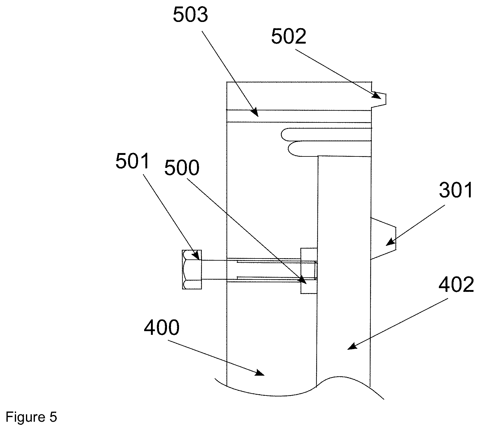
FIG. 5: shows a sectional representation of ejectors and assembly aids for a multiple-use casting mold;
FIG. 6: shows a representation of a set of single-use molds for producing the complex cast part;
FIG. 7: shows a sectional view of a component treated according to the invention;
FIG. 8: shows an illustration of the mold breakout process with a treatment according to the invention.
DETAILED DESCRIPTION
One example of a device for producing a molded part according to the present invention includes a powder coater (101). Particulate material is applied thereby to a building platform (102) and smoothed (FIG. 1). The applied particulate material may be made from a wide range of materials; according to the invention, however, sand is preferred for reasons of its low cost. This sand is precoated, for example, with an activator component. The height of powder layers (107) is determined by the building platform (102). It is lowered after one layer has been applied. During the next coating operation, the resulting volume is filled and the excess smoothed. The result is a nearly perfectly parallel and smooth layer of a defined height.
After a coating process, a fluid is printed onto the layer with the aid of an ink-jet print head (100). The print image corresponds to the section of the component in the present build height of the device. The fluid strikes and slowly diffuses into the particulate material.
The fluid reacts with the activator in the particulate material to form a polymer. The latter binds the particles to each other.
In the next step, the building platform (102) is lowered by the distance of one layer thickness. The steps of layer construction, printing and lowering are now repeated until the desired component (103) is completely produced.
The component (103) is now complete, and it is located in the powder cake (114). In the final step, the component is freed of the loose particulate material and cleaned with compressed air.
A component produced in this manner forms the basis for the present invention. The use of these molds may be divided into two areas: single-use molds and multiple-use molds. According to the present invention, they may be used in cold-casting methods.
FIG. 2 shows a simple cast part (200). It is economical to achieve multiple castings with the aid of one mold. A larger and more complex component is represented, for example, by a sink (300) in FIG. 3. The sink has a bowl-shaped formation (301) in its middle. An opening (303) for the later drain is situated in its center. Another opening (302) for the faucet is situated in the rectangular part of the basin.
As a single-use mold (600), breakout is achieved by destroying the mold. The mold is expediently produced as a thin bowl. The structure is additionally reinforced by means of ribbing to withstand the hydrostatic pressures. FIG. 6 shows a mold of this type. The mold is designed in two parts (600, 601).
FIG. 4 shows a multiple-use mold. It comprises two halves (400, 401), each of which has a thick-walled design, and into which the cavity (402) for the casting material is introduced. A sprue (403) is also provided.
The mold (400, 401; 600, 601) may be produced, for example, from a sand having an average grain size of 140 .mu.m, which was premixed with a hardener for a so-called cold resin in the amount of 0.3 wt %. The binding process preferably takes place with a concentration of cold resin in the range of 1.0 to 2.5 wt %.
After the printing process, the mold may be removed from the loose sand and cleaned.
Different methods may be used to modify the pore size. For example, an infiltration with a two-component polymer is possible. However, the material must be used in such a way that, according to the invention, pores which facilitate easy mold breakout remain on the surface after treatment. For this purpose, the mold is treated, for example, with an adapted seal, which is processed at room temperature and does not develop high strengths.
It is likewise possible to additionally use a black wash from the metal casting field. Smaller particles are applied to the surface in this case. The effective pore cross section is modified thereby. As a result, it is possible to prevent, for example, the mechanically weak seal according to the invention from being pressed into the mold due to high hydrostatic pressures.
Grease may be used as a simple seal according to the invention. The grease may be applied to the mold by spreading or spraying it on. The grease muse be suitably selected for the task. Too heavy a grease may be difficult to process. Too thin a grease or oil infiltrates the mold and thus no longer provides a sealing function.
After spreading or brushing, the grease may be additionally smoothed. A superficial application of heat is suitable for this purpose. This may be done, for example, with a hot air gun or a blowtorch. Thoroughly heating the mold is not desirable, since this may lead to the possibility of leaks in the seal.
The use of wax is also possible according to the invention. The wax is expediently liquefied by heating for processing. The low viscosity must be increased by means of a thickener; for example, polystyrene microgranulates may be used for this purpose. It is also possible to use hydrophobic solvents, such as the alkanes or benzine, to create a wax solution whose viscosity may be effectively adjusted.
A seal made from hot water-soluble polyvinyl alcohol may also be created. This material is dissolved in hot water and applied to the preheated mold. The mixing water of a concrete is unable to attack the seal.
FIG. 7 shows the process on the microscopic level. The molded body is constructed with the aid of particles (700), which are bonded to each other. Fine particles (702) collect on the geometric component boundary (701) in the event of a black-washed component. The seal (703) seals the surface water-tight.
The molds prepared in this manner are subsequently equipped with additional function components.
For example, ejectors (500, 501) may be inserted into multiple-use molds for easier breakout from the mold. Depending on the expected breakout forces, the seat of the ejectors in the printed mold was reinforced in advance, e.g., using an epoxy resin infiltration. The ejectors may be designed as bolts (501), which engage with a nut (500), which may be countersunk into the printed part. A force is then generated between the mold and the cast part by applying a torque to the bolt.
The mold may also be provided with centering pins. These pins minimize the offset between the mold halves and thus ensure a precise cast part.
Some structures known from metal casting molds may be provided directly on the printed part. Thus, centering elements (603) may be implemented, and labyrinth seals (502) may be mounted for a better sealing action between the mold halves.
The reinforcement is inserted into the mold cavity (402) before the molds are closed. It is expediently held at a distance relative to the mold with the aid of plastic or concrete supports. In this state, empty conduits may also be inserted into the mold for later introduction of electric lines or other media.
The assembly of the molds may be facilitated by bores (503) in the molds. Bolts, which apply the compressive forces onto critical mold areas in a targeted manner, may be guided through these bores. Additional plates may also be screwed on, which reinforce the mold against the casting forces.
Casting takes place through mounted sprues (403) or material shafts. Depending on the technique and casting material used, additional ventilation bores (602) may also be introduced. If a vibrator is to be inserted after casting to compress the casting material, an access is provided in the mold. Mold parts (e.g. 601), which are able to float, due to the pressure of the casting material, must be prevented from changing position, e.g. by being weighted down.
After the casting process, the part rests for up to several days, depending on the binding time of the casting material. The demolding process then takes place.
Due to the low strength of the seal, the latter is easily removed from the pores of the mold during breakout (see FIG. 8). This process may be assisted by heating the mold together with the cast part. As a result of the low separating forces, even delicate cast parts may be safely broken out of the mold.
If a single-use mold is used, the mold may be pre-damaged by hitting it with a hammer in a targeted manner. Depending on the wall thickness of the mold, the actual separation process is carried out with the aid of a putty knife or another flat tool. The mold may also be separated from the cast body by means of sand blasting. The selection of the blasting material and the pressure must be adapted according to the hardness of the casting material, so that the casting material is not damaged.
The multiple-use mold is preferably placed in a furnace before breakout and heated overnight to a temperature of, for example, 60.degree. C. Air circulation should be avoided to prevent drying out if concrete is used as the casting material.
After the furnace process, the bond between the mold and cast part is stressed by tightening the bolts on the ejectors. The mold then usually opens with the aid of slight vibrations or hammer blows.
After the casting process, the sealing medium (801) must be removed from the cast part (800). If grease is used, soaps and washing pastes for cleaning oils and greases are helpful. Hand washing paste that includes cleansing particles is particularly preferred in this case.
After casting, the parts are further processed as in the case of conventional production methods. The usual methods such as grinding or sand blasting are used for surface modification.
LIST OF REFERENCE NUMERALS
100 Print head 101 Coater 102 Building platform 103 Component 104 Build container 105 Print head path 106 Coater path 107 Powder layers 108 Direction of building platform movement\ 109 Dosed droplets 110 Powder roll 111 Build space boundary 112 Coater gap 113 Coater stock 114 Powder Cake 200 Simple cast part 300 Complex cast part, sink 301 Bowl-shaped sink area 302 Hole for faucet 303 Hole for drain 400 Casting mold, top box 401 Casting mold, bottom box 402 Cavity for casting material 403 Sprue 500 Nut 501 Bolt 502 Labyrinth seal 503 Bore for assembly bolts 600 Sink mold, bottom box 601 Sink mold, top box 602 Ventilation bores 603 Mold centering element and contact point 604 Mold core for drain 605 Mold core for faucet 606 Mold cores for wall mounting 700 Particle 701 Geometric mold boundary 702 Particle of the black wash 703 Seal 800 Cast part 801 Drawn-out seal
* * * * *
References
D00000
D00001
D00002
D00003
D00004
D00005
D00006
D00007
D00008
XML
uspto.report is an independent third-party trademark research tool that is not affiliated, endorsed, or sponsored by the United States Patent and Trademark Office (USPTO) or any other governmental organization. The information provided by uspto.report is based on publicly available data at the time of writing and is intended for informational purposes only.
While we strive to provide accurate and up-to-date information, we do not guarantee the accuracy, completeness, reliability, or suitability of the information displayed on this site. The use of this site is at your own risk. Any reliance you place on such information is therefore strictly at your own risk.
All official trademark data, including owner information, should be verified by visiting the official USPTO website at www.uspto.gov. This site is not intended to replace professional legal advice and should not be used as a substitute for consulting with a legal professional who is knowledgeable about trademark law.