Methods and systems for controlling a mild hybrid system that powers a transport climate control system
Schumacher , et al. February 23, 2
U.S. patent number 10,926,610 [Application Number 16/176,802] was granted by the patent office on 2021-02-23 for methods and systems for controlling a mild hybrid system that powers a transport climate control system. This patent grant is currently assigned to Thermo King Corporation. The grantee listed for this patent is THERMO KING CORPORATION. Invention is credited to Ryan Wayne Schumacher, Matthew Srnec.


| United States Patent | 10,926,610 |
| Schumacher , et al. | February 23, 2021 |
Methods and systems for controlling a mild hybrid system that powers a transport climate control system
Abstract
Methods and systems for controlling energy source for a mild hybrid system that powers a transport climate control system are provided. The mild hybrid system includes a DC energy source configured to supply a first DC voltage to the transport climate control system. The system also includes an inverter connected to the DC energy source and configured to change the first DC voltage from the DC energy source to a first AC voltage. The system further includes a transformer connected to the inverter and configured to convert the first AC voltage to a second AC voltage. Also the system includes a motor that drives a compressor. The motor is driven by the second AC voltage, the second AC voltage is greater than the first AC voltage.
| Inventors: | Schumacher; Ryan Wayne (Bloomington, MN), Srnec; Matthew (Minnetonka, MN) | ||||||||||
|---|---|---|---|---|---|---|---|---|---|---|---|
| Applicant: |
|
||||||||||
| Assignee: | Thermo King Corporation
(Minneapolis, MN) |
||||||||||
| Family ID: | 1000005375804 | ||||||||||
| Appl. No.: | 16/176,802 | ||||||||||
| Filed: | October 31, 2018 |
Prior Publication Data
| Document Identifier | Publication Date | |
|---|---|---|
| US 20200130473 A1 | Apr 30, 2020 | |
| Current U.S. Class: | 1/1 |
| Current CPC Class: | B60L 50/51 (20190201); B60L 1/003 (20130101); B60H 1/3232 (20130101); B60L 2210/12 (20130101); B60L 2210/20 (20130101); B60L 2210/42 (20130101); B60L 2210/30 (20130101) |
| Current International Class: | B60H 1/32 (20060101); B60L 1/00 (20060101); B60L 50/51 (20190101) |
References Cited [Referenced By]
U.S. Patent Documents
| 3875483 | April 1975 | Farr |
| 5104037 | April 1992 | Karg et al. |
| 6280320 | August 2001 | Paschke et al. |
| 6487869 | December 2002 | Sulc et al. |
| 6518727 | February 2003 | Oomura et al. |
| 6560980 | May 2003 | Gustafson et al. |
| 6600237 | July 2003 | Meissner |
| 6631080 | October 2003 | Trimble et al. |
| 6688125 | February 2004 | Okamoto et al. |
| 6753692 | June 2004 | Toyomura et al. |
| 7011902 | March 2006 | Pearson |
| 7120539 | October 2006 | Krull et al. |
| 7122923 | October 2006 | Lafontaine et al. |
| 7151326 | December 2006 | Jordan |
| 7176658 | February 2007 | Quazi et al. |
| 7206692 | April 2007 | Beesley et al. |
| 7327123 | February 2008 | Faberman et al. |
| 7424343 | September 2008 | Kates |
| 7449798 | November 2008 | Suzuki et al. |
| 7532960 | May 2009 | Kumar |
| 7728546 | June 2010 | Tanaka et al. |
| 7730981 | June 2010 | McCabe et al. |
| 7745953 | June 2010 | Puccetti et al. |
| 7806796 | October 2010 | Zhu |
| 7830117 | November 2010 | Ambrosio et al. |
| 7898111 | March 2011 | Pistel |
| 7900462 | March 2011 | Hegar et al. |
| 8020651 | September 2011 | Zillmer et al. |
| 8030880 | October 2011 | Alston et al. |
| 8170886 | May 2012 | Luff |
| 8214141 | July 2012 | Froeberg |
| 8295950 | October 2012 | Wordsworth et al. |
| 8381540 | February 2013 | Alston |
| 8441228 | May 2013 | Brabee |
| 8476872 | July 2013 | Truckenbrod et al. |
| 8487458 | July 2013 | Steele et al. |
| 8541905 | September 2013 | Brabee |
| 8602141 | December 2013 | Yee et al. |
| 8626367 | January 2014 | Krueger et al. |
| 8626419 | January 2014 | Mitchell et al. |
| 8643216 | February 2014 | Lattin |
| 8643217 | February 2014 | Gietzold et al. |
| 8670225 | March 2014 | Nunes |
| 8723344 | May 2014 | Dierickx |
| 8760115 | June 2014 | Kinser et al. |
| 8764469 | July 2014 | Lamb |
| 8818588 | August 2014 | Ambrosio et al. |
| 8862356 | October 2014 | Miller |
| 8924057 | December 2014 | Kinser et al. |
| 8978798 | March 2015 | Dalum et al. |
| 9030336 | May 2015 | Doyle |
| 9061680 | June 2015 | Dalum |
| 9093788 | July 2015 | Lamb |
| 9102241 | August 2015 | Brabee |
| 9147335 | September 2015 | Raghunathan et al. |
| 9199543 | December 2015 | Brabee |
| 9313616 | April 2016 | Mitchell et al. |
| 9436853 | September 2016 | Meyers |
| 9440507 | September 2016 | Giovanardi et al. |
| 9463681 | October 2016 | Olaleye et al. |
| 9464839 | October 2016 | Rusignuolo et al. |
| 9557100 | January 2017 | Chopko et al. |
| 9562715 | February 2017 | Kandasamy |
| 9694697 | July 2017 | Brabee |
| 9738160 | August 2017 | Bae et al. |
| 9758013 | September 2017 | Steele |
| 9783024 | October 2017 | Connell et al. |
| 9784780 | October 2017 | Loftus et al. |
| 9825549 | November 2017 | Choi et al. |
| 9846086 | December 2017 | Robinson et al. |
| 9893545 | February 2018 | Bean |
| 9931960 | April 2018 | Tabatowski-Bush et al. |
| 9975403 | May 2018 | Rusignuolo et al. |
| 9975446 | May 2018 | Weber et al. |
| 9987906 | June 2018 | Kennedy |
| 10000122 | June 2018 | Wu et al. |
| 10148212 | December 2018 | Schumacher et al. |
| 10240847 | March 2019 | Thomas, Jr. |
| 2002/0113576 | August 2002 | Oomura et al. |
| 2003/0043607 | March 2003 | Vinciarelli et al. |
| 2003/0106332 | June 2003 | Okamoto et al. |
| 2003/0200017 | October 2003 | Capps et al. |
| 2005/0057210 | March 2005 | Ueda et al. |
| 2006/0284601 | December 2006 | Salasoo et al. |
| 2007/0052241 | March 2007 | Pacy |
| 2007/0131408 | June 2007 | Zeigler et al. |
| 2007/0192116 | August 2007 | Levitt |
| 2008/0023965 | January 2008 | Cagliari et al. |
| 2009/0121798 | May 2009 | Levinson |
| 2009/0126901 | May 2009 | Hegar et al. |
| 2009/0178424 | July 2009 | Hwang et al. |
| 2009/0229288 | September 2009 | Alston et al. |
| 2009/0314019 | December 2009 | Fujimoto et al. |
| 2009/0320515 | December 2009 | Bischofberger et al. |
| 2010/0230224 | September 2010 | Hindman |
| 2010/0312425 | December 2010 | Obayashi et al. |
| 2010/0320018 | December 2010 | Gwozdek et al. |
| 2011/0000244 | January 2011 | Reason et al. |
| 2011/0114398 | May 2011 | Bianco |
| 2011/0208378 | August 2011 | Krueger |
| 2011/0224841 | September 2011 | Profitt-Brown et al. |
| 2011/0241420 | October 2011 | Hering et al. |
| 2012/0000212 | January 2012 | Sanders et al. |
| 2012/0116931 | May 2012 | Meyers |
| 2012/0198866 | August 2012 | Zeidner |
| 2013/0000342 | January 2013 | Blasko et al. |
| 2013/0088900 | April 2013 | Park |
| 2013/0158828 | June 2013 | McAlister |
| 2013/0231808 | September 2013 | Flath et al. |
| 2014/0026599 | January 2014 | Rusignuolo et al. |
| 2014/0060097 | March 2014 | Perreault |
| 2014/0265560 | September 2014 | Leehey et al. |
| 2015/0081212 | March 2015 | Mitchell et al. |
| 2015/0188360 | July 2015 | Doane et al. |
| 2015/0231948 | August 2015 | Kennedy |
| 2015/0246593 | September 2015 | Larson et al. |
| 2015/0355288 | December 2015 | Yokoyama et al. |
| 2015/0360568 | December 2015 | Champagne et al. |
| 2016/0011001 | January 2016 | Emory et al. |
| 2016/0035152 | February 2016 | Kargupta |
| 2016/0280040 | September 2016 | Connell et al. |
| 2016/0285416 | September 2016 | Tiwari et al. |
| 2017/0030728 | February 2017 | Baglino et al. |
| 2017/0057323 | March 2017 | Neu et al. |
| 2017/0063248 | March 2017 | Lee |
| 2017/0098954 | April 2017 | Ferguson et al. |
| 2017/0217280 | August 2017 | Larson et al. |
| 2017/0259764 | September 2017 | Da Silva Carvalho et al. |
| 2017/0302200 | October 2017 | Marcinkiewicz |
| 2017/0349078 | December 2017 | Dziuba et al. |
| 2018/0029436 | February 2018 | Zaeri et al. |
| 2018/0029488 | February 2018 | Sjodin |
| 2018/0111441 | April 2018 | Menard et al. |
| 2018/0154723 | June 2018 | Anderson et al. |
| 2018/0170398 | June 2018 | Miller et al. |
| 2018/0201092 | July 2018 | Ahhuja et al. |
| 2018/0203443 | July 2018 | Newman |
| 2018/0222278 | August 2018 | Mizuma |
| 2018/0342876 | November 2018 | Agnew et al. |
| 2018/0342877 | November 2018 | Yoo et al. |
| 2018/0356870 | December 2018 | Rusignuolo |
| 2019/0092122 | March 2019 | Vanous et al. |
| 2019/0184838 | June 2019 | Lee et al. |
| 2019/0255914 | August 2019 | Ikeda et al. |
| 2019/0283541 | September 2019 | Adetola et al. |
| 2020/0086712 | March 2020 | Schumacher et al. |
| 2020/0086744 | March 2020 | Schumacher et al. |
| 2020/0101818 | April 2020 | Holmstrom et al. |
| 2020/0101820 | April 2020 | Wenger et al. |
| 2456117 | Oct 2001 | CN | |||
| 1885660 | Dec 2006 | CN | |||
| 2912069 | Jun 2007 | CN | |||
| 101713577 | May 2010 | CN | |||
| 202038315 | Nov 2011 | CN | |||
| 14539184 | Apr 2015 | CN | |||
| 104734178 | Jun 2015 | CN | |||
| 105711376 | Jun 2016 | CN | |||
| 106184252 | Dec 2016 | CN | |||
| 106766419 | May 2017 | CN | |||
| 106774131 | May 2017 | CN | |||
| 108074466 | May 2018 | CN | |||
| 108931006 | Dec 2018 | CN | |||
| 208306320 | Jan 2019 | CN | |||
| 208650989 | Mar 2019 | CN | |||
| 3817365 | Nov 1989 | DE | |||
| 29715576 | Dec 1997 | DE | |||
| 10138750 | Feb 2003 | DE | |||
| 10200637 | Oct 2003 | DE | |||
| 102011050719 | Dec 2012 | DE | |||
| 0282051 | Sep 1988 | EP | |||
| 1935712 | Jun 2008 | EP | |||
| 2365915 | Sep 2011 | EP | |||
| 2689944 | Jan 2014 | EP | |||
| 2717016 | Sep 2014 | EP | |||
| 3343728 | Jul 2018 | EP | |||
| 3536552 | Sep 2019 | EP | |||
| 3540340 | Sep 2019 | EP | |||
| 2551999 | Jan 2018 | GB | |||
| 2000-158930 | Jun 2000 | JP | |||
| 2007-320352 | Dec 2007 | JP | |||
| 2009-243780 | Oct 2009 | JP | |||
| 2019-145521 | Aug 2019 | JP | |||
| 10-2012-0092834 | Aug 2012 | KR | |||
| 03038988 | May 2003 | WO | |||
| 2011066468 | Jun 2011 | WO | |||
| 2012/138497 | Oct 2012 | WO | |||
| 2013096084 | Jun 2013 | WO | |||
| 2014002244 | Jan 2014 | WO | |||
| 2014058610 | Apr 2014 | WO | |||
| 2014085672 | Jun 2014 | WO | |||
| 2014106060 | Jul 2014 | WO | |||
| 2014106068 | Jul 2014 | WO | |||
| 2016145107 | Sep 2016 | WO | |||
| 2017058660 | Apr 2017 | WO | |||
| 2017172484 | Oct 2017 | WO | |||
| 2017172855 | Oct 2017 | WO | |||
| 2017176682 | Oct 2017 | WO | |||
| 2017176725 | Oct 2017 | WO | |||
| 2017176729 | Oct 2017 | WO | |||
| 2017189485 | Nov 2017 | WO | |||
| 2017218909 | Dec 2017 | WO | |||
| 2017218910 | Dec 2017 | WO | |||
| 2017218912 | Dec 2017 | WO | |||
| 2018/009798 | Jan 2018 | WO | |||
| 2018005957 | Jan 2018 | WO | |||
| 2018009646 | Jan 2018 | WO | |||
| 2018009798 | Jan 2018 | WO | |||
| 2018017818 | Jan 2018 | WO | |||
| 2018029502 | Feb 2018 | WO | |||
| 2018/204591 | Nov 2018 | WO | |||
| 2018204591 | Nov 2018 | WO | |||
| 2018226389 | Dec 2018 | WO | |||
| 2018226649 | Dec 2018 | WO | |||
| 2018226848 | Dec 2018 | WO | |||
| 2018226857 | Dec 2018 | WO | |||
| 2018226862 | Dec 2018 | WO | |||
| 2018226906 | Dec 2018 | WO | |||
| 2018226981 | Dec 2018 | WO | |||
| 2018226986 | Dec 2018 | WO | |||
| 2019051086 | Mar 2019 | WO | |||
| 2019151947 | Aug 2019 | WO | |||
| 2020068446 | Apr 2020 | WO | |||
| 2020068450 | Apr 2020 | WO | |||
| 2020068469 | Apr 2020 | WO | |||
| 2020068475 | Apr 2020 | WO | |||
| 2020068502 | Apr 2020 | WO | |||
| 2020068556 | Apr 2020 | WO | |||
| 2020068641 | Apr 2020 | WO | |||
| 2020068646 | Apr 2020 | WO | |||
| 2020069107 | Apr 2020 | WO | |||
Other References
|
Yang et al., "The Role of Thermal Plume in Person-to-Person Contaminant Cross Transmission", 2017 Winter Conference, Seminar 36; Modeling and Control of the Personal Microenvironment, 5 pages. cited by applicant . "Lamberet Smart Reefer on Solutrans", Zoeken, Jul. 28, 2015, 7 pages, available at: https://iepieleaks.nl/lamberet-smart-reefer-solutrans/. cited by applicant . U.S. Appl. No. 16/178,067, titled "Methods and Systems for Generation and Utilization of Supplemental Stored Energy for Use in Transport Climate Control", filed Nov. 1, 2018, 35 pages. cited by applicant . U.S. Appl. No. 16/565,063, titled "System and Method for Managing Power and Efficiently Sourcing a Variable Voltage for a Transport Climate Control System", filed Sep. 9, 2019, 59 pages. cited by applicant . U.S. Appl. No. 16/574,754, titled "Methods and Systems for Energy Management of a Transport Climate Control System", filed Sep. 18, 2019, 50 pages. cited by applicant . U.S. Appl. No. 16/574,775, titled "Methods and Systems for Power and Load Management of a Transport Climate Control System", filed Sep. 18, 2019, 68 pages. cited by applicant . European Patent Application No. 18382672.6, titled "Methods and Systems for Energy Management of a Transport Climate Control System", filed Sep. 19, 2018, 50 pages. cited by applicant . European Patent Application No. 18382673.4 titled "Methods and Systems for Power and Load Management of a Transport Climate Control System", filed Sep. 19, 2018, 68 pages. cited by applicant . U.S. Appl. No. 16/235,865, titled "Methods and Systems for Preserving Autonomous Operation of a Transport Climate Control System", filed Dec. 28, 2018, 50 pages. cited by applicant . U.S. Appl. No. 16/176,720, titled "Methods and Systems for Augmenting a Vehicle Powered Transport Climate Control System", filed Oct. 31, 2018, 33 pages. cited by applicant . U.S. Appl. No. 16/176,667, titled "Drive Off Protection System and Method for Preventing Drive Off", filed Oct. 31, 2018, 41 pages. cited by applicant . U.S. Appl. No. 16/176,602, titled "Reconfigurable Utility Power Input With Passive Voltage Booster", filed Oct. 31, 2018, 39 pages. cited by applicant . U.S. Appl. No. 16/147,704, titled "Methods and Systems for Monitoring and Displaying Energy Use and Energy Cost of a Transport Vehicle Climate Control System or a Fleet of Transport Vehicle Climate Control Systems", filed Sep. 29, 2018, 33 pages. cited by applicant . U.S. Appl. No. 16/147,708, titled "Methods and Systems for Autonomous Climate Control Optimization of a Transport Vehicle", filed Sep. 29, 2018, 41 pages. cited by applicant . PCT International Application No. PCT/US2018/068136, titled "Methods and Systems for Providing Predictive Energy Consumption Feedback for Powering a Transport Climate Control System", filed Dec. 31, 2018, 34 pages. cited by applicant . PCT International Application No. PCT/US2018/068129, titled "Methods and Systems for Notifying and Mitigating a Suboptimal Event Occurring in a Transport Climate Control System", filed Dec. 31, 2018, 44 pages. cited by applicant . PCT International Application No. PCT/US2018/068139, titled "Methods and Systems for Providing Feedback for a Transport Climate Control System", filed Dec. 31, 2018, 37 pages. cited by applicant . PCT International Application No. PCT/US2018/068142, titled "Methods and Systems for Providing Predictive Energy Consumption Feedback for Powering a Transport Climate Control System Using External Data", filed Dec. 31, 2018, 39 pages. cited by applicant . U.S. Appl. No. 16/236,938, titled "Systems and Methods for Smart Load Shedding of a Transport Vehicle While in Transit", filed Dec. 31, 2018, 39 pages. cited by applicant . U.S. Appl. No. 16/565,110, titled "Transport Climate Control System With a Self-Configuring Matrix Power Converter", filed Sep. 9, 2019, 52 pages. cited by applicant . U.S. Appl. No. 16/565,146, titled "Optimized Power Management for a Transport Climate Control Energy Source", filed Sep. 9, 2019, 53 pages. cited by applicant . U.S. Appl. No. 62/897,833, titled "Optimized Power Distribution to Transport Climate Control Systems Amongst One or More Electric Supply Equipment Stations", filed Sep. 9, 2019, 41 pages. cited by applicant . European Patent Application No. 19382776.3, titled "Mprioritized Power Delivery for Facilitating Transport Climate Control", filed Sep. 9, 2019, 41 pages. cited by applicant . U.S. Appl. No. 16/565,205, titled "Transport Climate Control System With an Accessory Power Distribution Unit for Managing Transport Climate Control Loads", filed Sep. 9, 2019, 54 pages. cited by applicant . U.S. Appl. No. 16/565,235, titled "Interface System for Connecting a Vehicle and a Transport Climate Control System", filed Sep. 9, 2019, 64 pages. cited by applicant . U.S. Appl. No. 16/565,252, titled "Demand-Side Power Distribution Management for a Plurality of Transport Climate Control Systems", filed Sep. 9, 2019, 44 pages. cited by applicant . U.S. Appl. No. 16/565,282, titled "Optimized Power Cord for Transferring Power to a Transport Climate Control System", filed Sep. 9, 2019, 43 pages. cited by applicant . Extended European Search Report, issued in the corresponding European patent application No. EP 19205724.8, dated Mar. 30, 2020, 7 pages. cited by applicant. |
Primary Examiner: Norman; Marc E
Attorney, Agent or Firm: Hamre, Schumann, Mueller & Larson, P.C.
Claims
What is claimed is:
1. A mild hybrid system for powering a transport climate control system, comprising: a DC energy source configured to supply a first DC voltage to the transport climate control system; an inverter connected to the DC energy source and configured to change the first DC voltage from the DC energy source to a first AC voltage; a transformer connected to the inverter and configured to convert the first AC voltage to a second AC voltage; a motor connected to the transformer and configured to drive a compressor of the transport climate control system; an AC to DC converter; a DC to DC buck converter; and a DC load, wherein the motor is driven by the second AC voltage, the second AC voltage is greater than the first AC voltage, wherein the AC to DC converter converts the second AC voltage to a second DC voltage, the DC to DC buck converter converts the second DC voltage down to a third DC voltage.
2. The system of claim 1, further comprising: an AC load connected to the transformer, wherein the AC load is driven by the second AC voltage, and the AC load is one or more of an AC evaporator fan and an AC condenser fan.
3. The system of claim 1, wherein the first DC voltage is 48V.
4. The system of claim 1, wherein the second AC voltage is at least one of 230V and 460V.
5. The system of claim 1, wherein the motor is driven by one of a 230V AC and a 460V AC.
6. A mild hybrid system for powering a transport climate control system, comprising: a DC energy source configured to supply a first DC voltage to the transport climate control system; an inverter connected to the DC energy source and configured to change the first DC voltage from the DC energy source to a first AC voltage; a transformer connected to the inverter and configured to convert the first AC voltage to a second AC voltage; a motor connected to the transformer and configured to drive a compressor of the transport climate control system; an AC to DC to DC buck converter connected to the transformer; and a DC load connected to the AC to DC to DC buck converter, wherein the motor is driven by the second AC voltage, the second AC voltage is greater than the first AC voltage, wherein the AC to DC to DC buck converter converts the second AC voltage down to a second DC voltage supplied to the DC load.
7. The system of claim 6, wherein the second DC voltage drives the DC load, the DC load is one or more of a DC evaporator fan and a DC condenser fan.
8. The system of claim 6, wherein the first DC voltage drives the DC load, the DC load is one or more of a DC evaporator fan and a DC condenser fan, and the first DC voltage is equal to the second DC voltage.
9. A method for managing a mild hybrid system that powers a transport temperature control system, the method comprising: converting, by an inverter, a DC voltage from a DC energy source to a first AC voltage; converting, by a transformer, the first AC voltage to a second AC voltage, the second AC voltage being greater than the first AC voltage; driving a motor by the second AC voltage; driving a compressor of the transport climate control system by the motor, converting, via an AC to DC to DC buck converter, the second AC voltage down to a second DC voltage.
10. The method of claim 9, further comprising: driving an AC load by the second AC voltage, wherein the AC load is at least one of an AC evaporator fan and an AC condenser fan.
11. The method of claim 9, further comprising: driving a DC load by the second DC voltage, wherein the DC load is at least one of a DC evaporator fan and a DC condenser fan.
12. The method of claim 9, further comprising: driving a DC load by the first DC voltage, wherein the DC load is at least one of a DC evaporator fan and a DC condenser fan, and the first DC voltage is equal to the second DC voltage.
13. The method of claim 9, wherein the first DC voltage is 48V.
14. The method of claim 9, wherein the second AC voltage is one of 230V and 460V.
15. The method of claim 9, wherein the motor is driven by one of a 230V AC and a 460V AC.
Description
FIELD
This disclosure relates generally to energy source management for powering a transport climate control system. More specifically, the disclosure relates to methods and systems for managing and controlling a mild hybrid system that powers a transport climate control system.
BACKGROUND
A transport climate control system can include, for example, a transport refrigeration system (TRS) and/or a heating, ventilation and air conditioning (HVAC) system. A TRS is generally used to control an environmental condition (e.g., temperature, humidity, air quality, and the like) within a cargo space of a transport unit (e.g., a truck, a container (such as a container on a flat car, an intermodal container, etc.), a box car, a semi-tractor, a bus, or other similar transport unit). The TRS can maintain environmental condition(s) of the cargo space to maintain cargo (e.g., produce, frozen foods, pharmaceuticals, etc.). In some embodiments, the transport unit can include a HVAC system to control a climate within a passenger space of the vehicle.
SUMMARY
Regulations to reduce emissions (e.g., particulate matter emissions, nitrogen oxide emissions, noise emissions, etc.), for example, from a vehicle prime mover (e.g., a combustion engine such as a diesel engine, etc.), have led to components within the vehicle being electrically driven and the addition of emission reducing components (e.g., emission control devices, an auto start-stop system, etc.) in the space between the vehicle alternator and the prime mover within a vehicle power bay. As such, utility power (shore power) is used more often to charge and/or power the electrified components. For a transport climate control system, factory standard electric standby options (such as 230V/460V motor, etc.) are used frequently to work together with the utility power. Electrification requirements also lead to more usage of a battery pack (e.g., 24V/48V battery pack). High voltage battery packs that match the voltage requirements of the factory standard electric standby options can be cost prohibitive. The embodiments disclosed herein provide a cost effective design to control an energy source for a mild hybrid system that powers a transport climate control system. The mild hybrid system can address issues such as incompatibility of the voltages (e.g., the voltage of the battery pack and the voltage required for a factory standard electric motor, etc.).
In one embodiment, a mild hybrid system for a transport climate control system is provided. The mild hybrid system includes a DC energy source configured to supply a first DC voltage to the transport climate control system. The system also includes an inverter connected to the DC energy source and configured to change the first DC voltage from the DC energy source to a first AC voltage. The system further includes a transformer connected to the inverter and configured to convert the first AC voltage to a second AC voltage. Also the system includes a motor that drives a compressor. The motor is driven by the second AC voltage, the second AC voltage is greater than the first AC voltage.
In another embodiment, a method for managing a mild hybrid system that powers a transport temperature control system is provided. The method includes converting, by an inverter, a DC voltage from a DC energy source to a first AC voltage. The method also includes converting, by a transformer, the first AC voltage to a second AC voltage. The second AC voltage is greater than the first AC voltage. The method further includes driving a motor by the second AC voltage. Also the method includes driving a compressor by the motor.
Other features and aspects will become apparent by consideration of the following detailed description and accompanying drawings.
BRIEF DESCRIPTION OF THE DRAWINGS
References are made to the accompanying drawings that form a part of this disclosure and which illustrate the embodiments in which systems and methods described in this specification can be practiced.
FIG. 1A illustrates a side view of a truck with a front wall mounted vehicle powered transport refrigeration unit, according to one embodiment.
FIG. 1B illustrates a schematic cross sectional side view of a refrigerated transport unit with a multi-temp transport refrigeration system, according to one embodiment.
FIG. 1C illustrates a perspective view of a vehicle with an APU, according to one embodiment.
FIG. 1D illustrates a front perspective view of an APU, according to one embodiment.
FIG. 1E illustrates a side view of a van with a roof mounted vehicle powered transport refrigeration unit, according to one embodiment.
FIG. 2A illustrates a mild hybrid system for powering a transport climate control system, according to one embodiment.
FIG. 2B illustrates a mild hybrid system for powering a transport climate control system, according to another embodiment.
FIG. 2C illustrates a mild hybrid system for powering a transport climate control system, according to yet another embodiment.
FIG. 3 is a flow chart illustrating a method for managing a mild hybrid system that powers a transport temperature control system, according to one embodiment.
Like reference numbers represent like parts throughout.
DETAILED DESCRIPTION
This disclosure relates generally to energy source management for powering a transport climate control system. More specifically, the disclosure relates to methods and systems for managing and controlling a mild hybrid system that powers a transport climate control system.
The embodiments disclosed herein can provide a cost effective design to control an energy source of a mild hybrid system that powers a transport climate control system.
As defined herein, the phrase "mild hybrid" refers to a hybrid system that includes an energy storage system (e.g., a rechargeable energy storage system) that is not capable of providing sufficient energy/power to support operation of the transport climate control system at full capacity by itself.
As defined herein, the phrase "full hybrid" refers to a hybrid system that includes an energy storage system (e.g., a rechargeable energy storage system) that may be capable of providing sufficient energy/power to support operation of the transport climate control system at full capacity by itself.
The embodiments described herein can provide an energy system in which a voltage of a battery pack requires a boost to match the voltage requirements of, for example, factory standard electric standby options.
FIG. 1A depicts a temperature-controlled straight truck 11 that includes a conditioned load space 12 for carrying cargo. A transport refrigeration unit (TRU) 14 is mounted to a front wall 16 of the load space 12. The TRU 14 is controlled via a controller 15 to provide temperature control within the load space 12. The truck 11 further includes a vehicle power bay 18, which houses a prime mover 21, such as a combustion engine (e.g., diesel engine, etc.), that provides power to move the truck 11 and to operate the TRU 14. In some embodiments, the prime mover 21 can work in combination with an optional machine 22 (e.g., an alternator) to operate the TRU 14. In one embodiment, the TRU 14 includes a vehicle electrical system. Also, in some embodiments, the truck 11 can be a hybrid vehicle that is powered by the prime mover 21 in combination with a battery power source or can be an electrically driven truck in which the prime mover 21 is replaced with an electric power source (e.g., a battery power source). While FIG. 1A illustrates a temperature-controlled straight truck 11, it will be appreciated that the embodiments described herein can also apply to any other type of transport unit including, but not limited to, a container (such as a container on a flat car, an intermodal container, etc.), a box car, or other similar transport unit.
FIG. 1B illustrates one embodiment of a MTRS 100 for a TU 125 that can be towed, for example, by a tractor (not shown). The MTRS 100 includes a TRU 110 that provides environmental control (e.g. temperature, humidity, air quality, etc.) within an internal space 150 of the TU 125. The MTRS 100 also includes a MTRS controller 170 and one or more sensors (e.g., Hall effect sensors, current transducers, etc.) that are configured to measure one or more parameters (e.g., ambient temperature, compressor suction pressure, compressor discharge pressure, supply air temperature, return air temperature, humidity, etc.) of the MTRS 100 and communicate parameter data to the MTRS controller 170. The MTRS 100 is powered by a power module 112. The TRU 110 is disposed on a front wall 130 of the TU 125. In other embodiments, it will be appreciated that the TRU 110 can be disposed, for example, on a rooftop 126 or another wall of the TU 125.
In some embodiments, the MTRS 100 can include an undermount unit 113. In some embodiments, the undermount unit 113 can be a TRU that can also provide environmental control (e.g. temperature, humidity, air quality, etc.) within the internal space 150 of the TU 125. The undermount unit 113 can work in combination with the TRU 110 to provide redundancy or can replace the TRU 110. Also, in some embodiments, the undermount unit 113 can be a power module that includes, for example, a generator that can help power the TRU 110.
The programmable MTRS Controller 170 may comprise a single integrated control unit or may comprise a distributed network of TRS control elements. The number of distributed control elements in a given network can depend upon the particular application of the principles described herein. The MTRS controller 170 is configured to control operation of the MTRS 100.
As shown in FIG. 1B, the power module 112 is disposed in the TRU 110. In other embodiments, the power module 112 can be separate from the TRU 110. Also, in some embodiments, the power module 112 can include two or more different power sources disposed within or outside of the TRU 110. In some embodiments, the power module 112 can include one or more of a prime mover, a battery, an alternator, a generator, a solar panel, a fuel cell, etc. Also, the prime mover can be a combustion engine or a microturbine engine and can operate as a two speed prime mover, a variable speed prime mover, etc. The power module 112 can provide power to, for example, the MTRS Controller 170, a compressor (not shown), a plurality of DC (Direct Current) components (not shown), a power management unit (not shown), etc. The DC components can be accessories or components of the MTRS 100 that require DC power to operate. Examples of the DC components can include, for example, DC fan motor(s) for a condenser fan or an evaporator blower (e.g., an Electrically Commutated Motor (ECM), a Brushless DC Motor (BLDC), etc.), a fuel pump, a drain tube heater, solenoid valves (e.g., controller pulsed control valves), etc.
The power module 112 can include a DC power source (not shown) for providing DC electrical power to the plurality of DC components (not shown), the power management unit (not shown), etc. The DC power source can receive mechanical and/or electrical power from, for example, a utility power source (e.g., Utility power, etc.), a prime mover (e.g., a combustion engine such as a diesel engine, etc.) coupled with a generator machine (e.g., a belt-driven alternator, a direct drive generator, etc.), etc. For example, in some embodiments, mechanical energy generated by a diesel engine is converted into electrical energy via a generator machine. The electrical energy generated via the belt driven alternator is then converted into DC electrical power via, for example, a bi-directional voltage converter. The bi-directional voltage converter can be a bi-directional multi-battery voltage converter.
The internal space 150 can be divided into a plurality of zones 152. The term "zone" means a part of an area of the internal space 150 separated by walls 175. It will be appreciated that the invention disclosed herein can also be used in a single zone TRS.
The MTRS 100 for the TU 125 includes the TRU 110 and a plurality of remote evaporator units 180. In some embodiments, an HVAC system can be powered by an Auxiliary Power Unit (APU, see FIGS. 1C and 1D). The APU can be operated when a main prime mover of the TU 125 is turned off such as, for example, when a driver parks the TU 125 for an extended period of time to rest. The APU can provide, for example, power to operate a secondary HVAC system to provide conditioned air to a cabin of the TU 125. The APU can also provide power to operate cabin accessories within the cabin such as a television, a microwave, a coffee maker, a refrigerator, etc. The APU can be a mechanically driven APU (e.g., prime mover driven) or an electrically driven APU (e.g., battery driven).
The tractor includes a vehicle electrical system for supplying electrical power to the electrical loads of the tractor, the MTRS 100, and/or the TU 125.
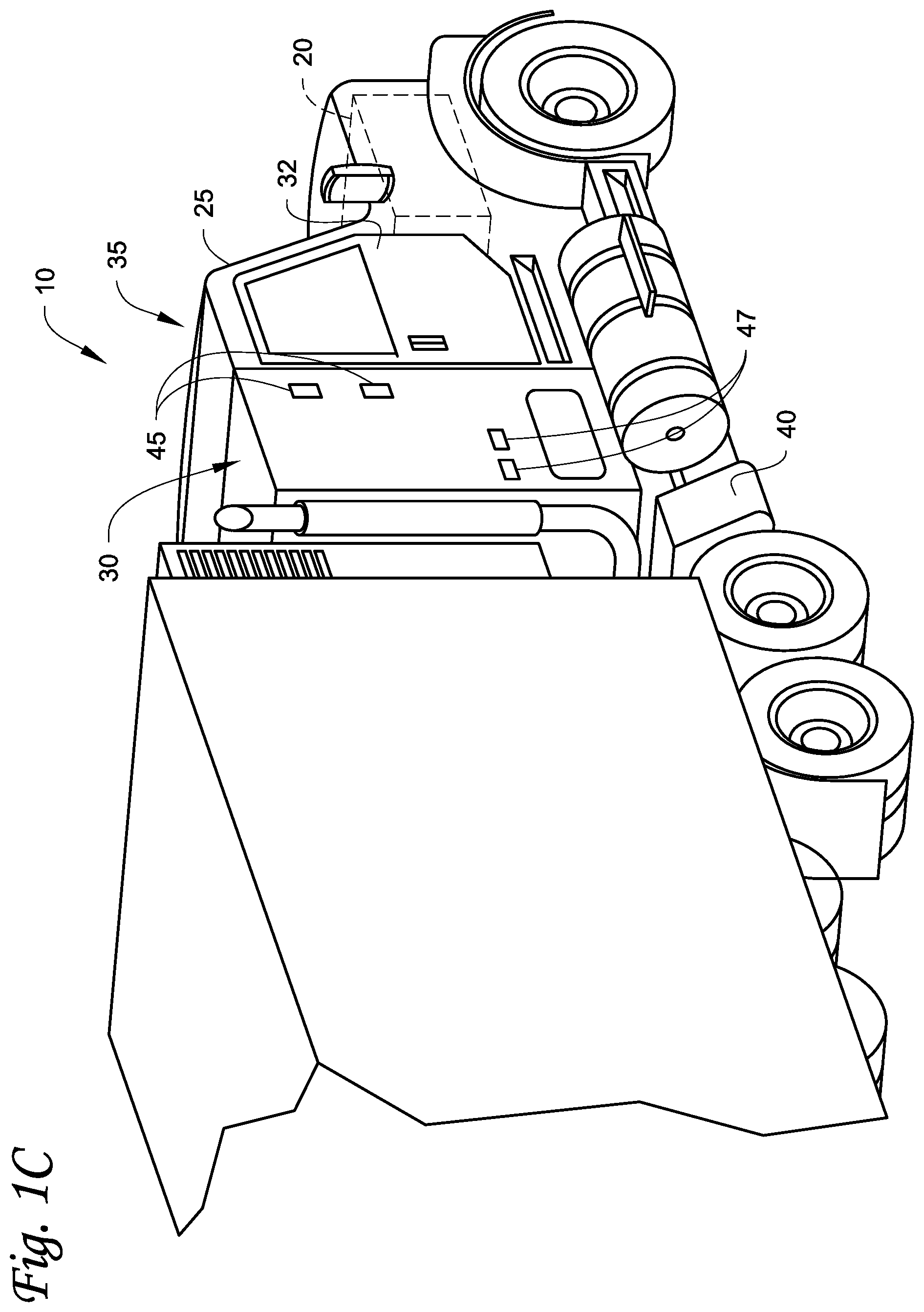
FIG. 1C illustrates a vehicle 10 according to one embodiment. The vehicle 10 is a semi-tractor that is used to transport cargo stored in a cargo compartment (e.g., a container, a trailer, etc.) to one or more destinations. Hereinafter, the term "vehicle" shall be used to represent all such tractors and trucks, and shall not be construed to limit the invention's application solely to a tractor in a tractor-trailer combination. In some embodiments, the vehicle 10 can be, for example, a straight truck, van, etc.
The vehicle 10 includes a primary power source 20, a cabin 25 defining a sleeping portion 30 and a driving portion 35, an APU 40, and a plurality of vehicle accessory components 45 (e.g., electronic communication devices, cabin lights, a primary and/or secondary HVAC system, primary and/or secondary HVAC fan(s), sunshade(s) for a window/windshield of the vehicle 10, cabin accessories, etc.). The cabin 25 can be accessible via a driver side door (not shown) and a passenger side door 32. The cabin 25 can include a primary HVAC system (not shown) that can be configured to provide conditioned air within driving portion 35 and potentially the entire cabin 25, and a secondary HVAC system (not shown) for providing conditioned air within the sleeping portion 30 of the cabin 25. The cabin 25 can also include a plurality of cabin accessories (not shown). Examples of cabin accessories can include, for example, a refrigerator, a television, a video game console, a microwave, device charging station(s), a continuous positive airway pressure (CPAP) machine, a coffee maker, a secondary HVAC system for providing conditioned air to the sleeping portion 30.
The primary power source 20 can provide sufficient power to operate (e.g., drive) the vehicle 10 and any of the plurality of vehicle accessory components 45 and cabin accessory components 47. The primary power source 20 can also provide power to the primary HVAC system and the secondary HVAC system. In some embodiments, the primary power source can be a prime mover such as, for example, a combustion engine (e.g., a diesel engine, etc.).
The APU 40 is a secondary power unit for the vehicle 10 when the primary power source 20 is unavailable. When, for example, the primary power source 20 is unavailable, the APU 40 can be configured to provide power to one or more of the vehicle accessory components, the cabin accessories, the primary HVAC system and the secondary HVAC system. In some embodiments, the APU 40 can be an electric powered APU. In other embodiments, the APU 40 can be a prime mover powered APU. The APU 40 can be attached to the vehicle 10 using any attachment method. In some embodiments, the APU 40 can be turned on (i.e., activated) or off (i.e., deactivated) by an occupant (e.g., driver or passenger) of the vehicle 10. The APU 40 generally does not provide sufficient power for operating (e.g., driving) the vehicle 10. The APU 40 can be controlled by an APU controller 41.
FIG. 1D illustrates an electric APU 140 that can be used with a vehicle (e.g., the vehicle 10 shown in FIG. 1C), according to one embodiment. The APU 140 includes a plurality of energy storage elements 60 each of which is coupled to one of a plurality of converters 70. The converters 70 can provide electric power (e.g., AC or DC power) generated by the APU 140 to one or more vehicle accessory components, cabin accessory components, a primary HVAC system, and a secondary HVAC system. A secondary HVAC system can provide conditioned air to a sleeping portion of a vehicle cabin (e.g., the sleeping portion 30 of the cabin 25 shown in FIG. 1C). The energy storage elements 60 can be, for example, battery packs, fuel cells, etc. In some embodiments, the APU 140 can be turned on or off by an occupant (e.g., driver or passenger) of the vehicle. For example, the occupant can turn on the APU 140 to provide power stored in the energy storage elements 60 when a primary power source of the vehicle is turned off. It will be appreciated that the embodiments described herein can also be used with a prime mover powered APU.
In some embodiments, the APU (e.g., the APU 40 as shown in FIG. 1C and/or the APU 140 as shown in FIG. 1D) includes a vehicle electrical system.
FIG. 1E depicts a temperature-controlled van 80 that includes a conditioned load space 82 (or internal space) for carrying cargo. A transport refrigeration unit (TRU) 85 is mounted to a rooftop 84 of the load space 82. The TRU 85 is controlled via a controller 83 to provide temperature control within the load space 82. The van 80 further includes a vehicle power bay 86, which houses a prime mover 87, such as a combustion engine (e.g., diesel engine, etc.), that provides power to move the van 80 and to operate the TRU 85. In some embodiments, the prime mover 87 can work in combination with an optional machine 88 (e.g., an alternator) to operate the TRU 85. In one embodiment, the TRU 85 includes a vehicle electrical system. Also, in some embodiments, the van 80 can be a hybrid vehicle that is powered by the prime mover 87 in combination with a battery power source or can be an electrically driven truck in which the prime mover 87 is replaced with an electric power source (e.g., a battery power source).
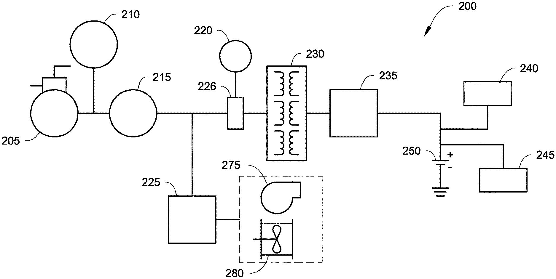
FIG. 2A illustrates a mild hybrid system 200 for powering a transport climate control system, according to one embodiment. The transport climate control system can include, for example, the transport refrigeration unit/system of FIGS. 1A, 1B, and 1E. The mild hybrid system 200 can include, for example, the APU of FIGS. 1C and 1D.
A mild hybrid system generally includes a prime mover (e.g., an internal combustion engine) equipped with an electric machine (for example, a motor/generator in a parallel hybrid configuration) configured to allow the prime mover to be turned off whenever the vehicle, for example, is coasting, braking, or stopped. Mild hybrid systems, as defined herein, do not require the same level of battery power as compared to full hybrid vehicles (which have high voltage battery pack etc.). It will be appreciated that a mild hybrid system can be a lower cost implementation of hybridization approach. Lower cost typically indicates less energy storage. Less energy storage typically makes for lower voltage. As such, less power can be generated from lower cost machines. It will also be appreciated that mild hybrid system can regenerate and provide power for some portions of the operating cycle but might not fit as many as those in the full hybrid system. Full hybrid system typically has a greater quantity of energy storage and generator power available compared with a mild hybrid system. Compared with a full hybrid system, an energy storage system (e.g., a rechargeable energy storage system) of the mild hybrid system is not capable of providing sufficient energy/power to support operation of the transport climate control system at full capacity by itself.
In a mild hybrid system, the energy storage system can be low voltage battery pack(s). In some embodiments, the low voltage battery pack(s) can be rechargeable battery pack(s). The voltage of the battery pack in the mild hybrid system can be, for example, 24V, 48V, 88V, 120V, 200V, etc. Factory standard electric standby options (such as 230 VAC/460 VAC motor, etc.) are used frequently to work together with the utility power. By definition, mild hybrid is a system where the voltage of the energy storage (e.g., battery pack) requires a boost to match the voltage requirements of the electric components (e.g., factory standard electric motor) that need to be driven. For example, the voltage of the energy storage (e.g., battery pack) is 48V and the voltage requirements of the electric component (e.g., factory standard electric motor) to be driven is 230 VAC/460 VAC, the voltage of the energy storage requires a boost to drive the electric component.
High voltage (defined as a voltage that matches the voltage requirements of the electric components to be driven) energy storage can be cost prohibitive. The embodiments disclosed herein provide a cost effective design to control an energy source for a mild hybrid system. However, there are safety reasons not to use high voltage DC for powering a transport climate control system. In some embodiments, high voltage batteries are not always be available. The embodiments disclosed herein provide a cost effective design to control an energy source for a mild hybrid system.
When a low voltage battery (e.g., 48V) is provided in the transport climate control system, in some embodiments, it may be difficult to find a motor (e.g., a low voltage DC motor, such as a 48V Electrically Commutated Motor (ECM)) that can fit in a transport refrigeration unit of the transport climate control system. Factory standard electric motors (e.g., 230 VAC/460 VAC motors that match the voltage of the utility power) are typically readily available. The embodiments disclosed herein can use a drive (e.g., a 48V inverter), and boost the output of the inverter to match the voltage of a factory standard electric motor, to run, for example, the transport climate control system.
In one embodiment, low voltage (in a mild hybrid system) can refer to a voltage greater than 0 VDC but equal to or less than 144 VDC (or greater than 0 VAC but equal to or less than 100 VAC). For example, the low voltage (in a mild hybrid system) can be, for example, 12 VDC, 24 VDC, 48 VDC, etc. In some embodiments, low voltage (in a mild hybrid system) can be 250 VDC or less. It will be appreciated that there are many inverters available that operate in the 12 VDC to 144 VDC range. For example, inverters for things such as golf carts which may not have HV battery pack.
In one embodiment, voltage requirements for an AC machine can be greater than 144 VDC but less than 1200 VDC (or greater than 100 VAC but equal to or less than 1000 VAC). Such voltage requirements typically include normal utility power of 100 VAC-506 VAC (one phase or three phases). Many AC machines are made to operate from utility power. Driving such AC machines from a low voltage network using a low voltage inverter can require a transformer (or auto transformer) to get the needed voltage requirements.
As shown in FIG. 2A, the system 200 includes a compressor 205 and a motor 215 that drives the compressor 205. The motor 215 can be a factory standard electric motor, such as a 230V (or 460V) AC motor. The system 200 further includes a prime mover 210. The prime mover 210 can be an internal combustion engine (e.g., a diesel prime engine). The motor 215 is connected to the compressor 205 to drive the compressor 205. The prime mover 210 is coupled (e.g., mechanically) to the motor 215 and the compressor 205. It will be appreciated that mechanical energy flows from the prime mover 210 to the compressor 205. It will also be appreciated that there can be clutches (not shown) for disconnecting the mechanical coupling. For example, a clutch can be used to disconnect the prime mover 210 and connect the motor 215 to drive the compressor 205. In another embodiment, the motor 215 can have a jack (or through shaft, etc.). The prime mover 210 and the compressor 205 (that are linked) can be connected to one end of the jack and loads (such as fan, etc.) can be connected to the other end of the jack. It will be appreciated that if the prime mover 210 drives the compressor 205, a rotor of the motor can be spinning along as dead load.
Also the system 200 includes a socket 220. The system 200 can connect to a utility power source (not shown) via the socket 220. The utility power source can provide power to drive the motor 215. Further the system 200 includes an AC load 225. The utility power source can provide power to drive the AC load 225.
The system 200 includes an energy storage 250. The energy storage 250 can be a TRU energy storage, a vehicle energy storage, etc. In some embodiments, the energy storage 250 can be a battery pack. The battery pack can be a low voltage battery pack to provide a mild hybrid energy source (e.g., no more than 250V), for example, 24V, 48V, 88V, 120V, 200V, 250V, etc. The system 200 also includes a generator 240. The generator 240 can be, for example, a solar power source. It will be appreciated that the generator 240 can be a high voltage generator. The generator 240 can be configured to charge the energy storage 250.
The system 200 can further include an energy network 245. The energy network 245 can provide power from a vehicle power source (e.g., APU, auxiliary/holdover battery, etc.). The energy network 245 can charge the energy storage 250.
Also the system 200 includes an inverter 235 and a transformer 230. The inverter 235 can invert the DC power from the energy storage 250, the energy network 245, and/or the generator 240 to a first AC power. The transformer 230 can convert the voltage of the first AC power from the inverter 235 to a second AC voltage. The second AC voltage matches the voltage requirements of, for example, the motor 215 and/or the AC load 225. An AC power output from the transformer 230 can drive the motor 215 and/or the AC load 225.
It will be appreciated that in one embodiment when the transformer 230 converts the voltage of the first AC power from the inverter 235 to a second AC voltage, the voltage can be stepped up (e.g., to drive a machine). In another embodiment, the voltage can be stepped down (e.g., to generate power from a machine) when the transformer 230 converts the voltage of the first AC power from the inverter 235 to a second AC voltage.
The socket 220 and the transformer 230 connect to a switch 226. It will be appreciated that a controller (such as the controller of FIGS. 1A-1E) can control the switch 226 so that either power from the utility power source (via the socket 220) or power from the transformer 230 can be used to drive the motor 215 and/or the AC load 225. For example, when the controller determines (via, e.g., a sensor) that a utility power source is connected, the controller can control the switch 226 so that only power from the utility power source (via the socket 220) can be used to drive the motor 215 and/or the AC load 225. When the controller determines (via, e.g., a sensor) that a utility power source is not connected, the controller can control the switch 226 so that power from the transformer 230 can be used to drive the motor 215 and/or the AC load 225.
It will be appreciated that in one embodiment, the prime mover 210 can mechanically drive a generator (not shown). The generator can generate electrical power to drive the motor 215. The motor 215 can mechanically drive the compressor 205.
It will also be appreciated that when the transformer 230 boosts the voltage of the first AC power from the inverter 235 to a second AC voltage, the boost circuit for boosting the voltage is a "passive boost circuit". A "passive boost circuit" refers to a booster circuit that only includes passive elements. A passive element is an electrical component that does not generate power, but instead dissipates, stores, and/or releases power. Passive elements include resistors, capacitors, inductors, transformers (can increase a voltage or current but cannot increase the power), diodes (when they do not have a negative differential resistance) etc. It will also be appreciated that "passive boost circuit" means that the boost circuit does not include any active elements. Active elements are elements that supply power to the circuit. Active elements include, for example, voltage and current sources, generators, transistors, etc. For example, unlike, an active voltage boost circuit, a passive boost circuit does not include transistor(s) or MOSFET(s). In one embodiment, the passive boost circuit can include the inverter 235.
It will be appreciated that transformer(s) are not usually used in a mild hybrid system because they are big (in space), heavy (in weight), and bulky and thus cannot be easily accommodated in the mild hybrid system. In one embodiment, the transformer(s) can be mounted on/under the transport unit (e.g., the transport unit 11 shown in FIG. 1A). Despite the bulkiness of the transformer, compared with a system with a DC-DC booster and then an inverter, and a system with a boosting invertor (which can be cost prohibitive), using transformer(s) in the mild hybrid system 200 can be cost effective (e.g., no extra switches required) and efficient. The embodiments disclosed herein can match the voltage of the energy storage to the voltage requirement level of the AC machine, without the use of a DC-DC boost converter. The transformer 230 enables the voltage from the drive (e.g., the inverter 235) to be at an appropriate level when it reaches the AC machine (e.g., motor 215).
It will also be appreciated that the AC load 225 can be one or more loads of the transport climate control system including, for example, an AC evaporator fan 275, a condenser fan 280, etc.
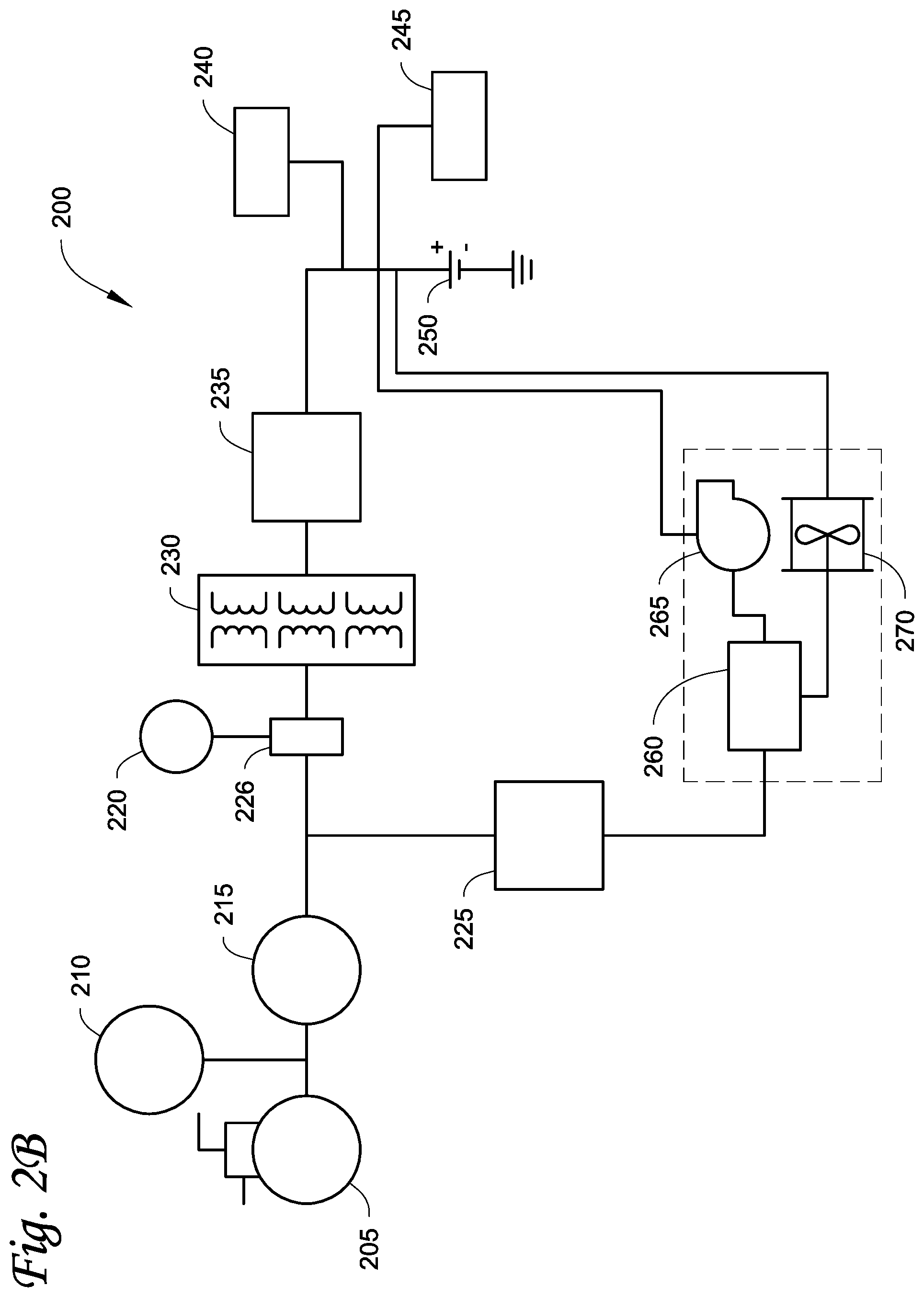
FIG. 2B illustrates a mild hybrid system 200 for powering a transport climate control system, according to another embodiment. It will be appreciated that the elements of FIG. 2B are similar to the elements of FIG. 2A, except as discussed below.
As shown in FIG. 2B, the system 200 can include an AC/DC/DC converter 260. It will be appreciated that the AC load 225 can include the AC/DC/DC converter 260. The system 200 can also include a DC evaporator fan 265 and/or a DC condenser fan 270. The DC power from the energy storage 250, the energy network 245, and/or the generator 240 can drive the DC evaporator fan 265 and/or the DC condenser fan 270.
In one embodiment, the AC/DC/DC converter 260 can include an AC to DC converter (not shown). The AC to DC converter can convert the AC power from the utility power (not shown) or from the transformer 230 to a DC voltage. The AC/DC/DC converter 260 can also include a DC to DC converter (not shown). The DC to DC converter can be a DC to DC buck converter that converts the DC voltage from the AC to DC converter down to a lower DC voltage. The lower DC voltage from the DC to DC buck converter can drive the DC evaporator fan 265 and/or the DC condenser fan 270.
In another embodiment, the AC/DC/DC converter 260 can include an AC to DC to DC buck converter (not shown). The AC to DC to DC buck converter can convert the AC power from the utility power (not shown) or from the transformer 230 to a DC voltage and then convert the DC voltage down to a lower DC voltage. The lower DC voltage can drive the DC evaporator fan 265 and/or the DC condenser fan 270.
FIG. 2C illustrates a mild hybrid system 200 for powering a transport climate control system, according to yet another embodiment. It will be appreciated that the elements of FIG. 2C are similar to the elements of FIGS. 2A and 2B, except as discussed below.
As shown in FIG. 2C, the motor 215 can extract excess power from the prime mover 210, using for example, an inverter (not shown), to drive the generator 240. The generator 240 can be configured to charge the energy storage 250. It will be appreciated that the power generated from the generator 240 can also be used to drive the loads 225 and/or the compressor 205, as described in FIGS. 2A and 2B. It will be appreciated that there can be excess power capacity with the prime mover 210 when the prime mover 210 is running, and there can be a ban on running the prime mover 210 in certain scenarios (e.g., in city areas). In addition, there can be instances where adding additional load on the prime mover 210 can lead to a marginal increase in fuel usage and/or emissions. As such, when the prime mover 210 is running, the excess power can be taken and stored in, for example, the energy storage 250, so that when the vehicle drives into city areas, there can be power available from an emission free source (such as the energy storage 250).
FIG. 3 is a flow chart illustrating a method 300 for managing a mild hybrid system that powers a transport temperature control system, according to one embodiment.
As shown in FIG. 3, the method begins at 310 whereby a device (such as the inverter 235 of FIGS. 2A, 2B, and 2C) converts a DC voltage (e.g., 24V, 48V, 88V, 120V, 200V, etc.) from a DC energy source (such as the energy storage 250 of FIGS. 2A, 2B and 2C) to a first AC voltage (e.g., AC voltage that corresponding to the DC voltage). It will be appreciated that corresponding to the DC voltage to be converted (i.e., the VDC) via the inverter, the converted AC voltage can be at or about VDC/sqrt(2). For example, the converted AC voltage corresponding to a 24 VDC is at or about 24/2.sup.1/2 VAC, the converted AC voltage corresponding to a 48 VDC is at or about 48/2.sup.1/2 VAC, etc. It will further be appreciated that at 310, a DC load can be driven by the first DC voltage. The DC load can be a DC evaporator fan, a DC condenser fan, etc. The method proceeds to 320.
At 320, a transformer (such as the transformer 230 of FIGS. 2A, 2B, and 2C) converts the first AC voltage to a second AC voltage (e.g., 230 VAC, 460 VAC, etc.). The second AC voltage matches the voltage requirements of, for example, the motor 215 and/or the AC load 225 of FIGS. 2A and 2B. The second AC voltage is greater than the first AC voltage. The method proceeds to 330.
At 330, a load (such as the motor 215 of FIGS. 2A, 2B, and 2C, etc.) connected to the transformer is driven by the second AC voltage. It will be appreciated that at 330, an AC load (such as the AC load 225 of FIGS. 2A, 2B, and 2C) connected to the transformer can be driven by the second AC voltage. The AC load can be, for example, an AC evaporator fan, an AC condenser fan, etc. Also, it will be appreciated that in one embodiment at 330, an AC to DC converter can convert the second AC voltage to a second DC voltage. Then a DC to DC buck converter can convert the second DC voltage down to a third DC voltage (e.g., 24V, 48V, 88V, 120V, 200V, etc.). It will also be appreciated that in another embodiment at 330, an AC to DC to DC buck converter can convert the second AC voltage down to a lower DC voltage (e.g., 24V, 48V, 88V, 120V, 200V, etc.). It will be appreciated that the first DC voltage can be equal to the lower third DC voltage. The method proceeds to 340.
At 340, the load (such as the motor 215 of FIGS. 2A, 2B, and 2C, or a fan, etc.) drives a device (such as the compressor 205 of FIGS. 2A and 2B) of the transport climate control system. It will be appreciated that at 340, a DC load can be driven by the third/lower DC voltage. The DC load can be, for example, a DC evaporator fan, a DC condenser fan, etc.
Aspects
It is appreciated that any of aspects 1-9 and 10-18 can be combined.
Aspect 1. A mild hybrid system for powering a transport climate control system, comprising:
a DC energy source configured to supply a first DC voltage to the transport climate control system;
an inverter connected to the DC energy source and configured to change the first DC voltage from the DC energy source to a first AC voltage;
a transformer connected to the inverter and configured to convert the first AC voltage to a second AC voltage; and
a motor connected to the transformer and configured to drive a compressor of the transport climate control system,
wherein the motor is driven by the second AC voltage, the second AC voltage is greater than the first AC voltage.
Aspect 2. The system of aspect 1, further comprising:
an AC load connected to the transformer,
wherein the AC load is driven by the second AC voltage, and the AC load is one or more of an AC evaporator fan and an AC condenser fan.
Aspect 3. The system of aspect 1, further comprising:
an AC to DC converter;
a DC to DC buck converter; and
a DC load,
wherein the AC to DC converter converts the second AC voltage to a second DC voltage, the DC to DC buck converter converts the second DC voltage down to a third DC voltage.
Aspect 4. The system of aspect 1, further comprising:
an AC to DC to DC buck converter connected to the transformer; and
a DC load connected to the AC to DC to DC buck converter,
wherein the AC to DC to DC buck converter converts the second AC voltage down to a second DC voltage supplied to the DC load.
Aspect 5. The system of aspect 4, wherein the second DC voltage drives the DC load, the DC load is one or more of a DC evaporator fan and a DC condenser fan.
Aspect 6. The system of aspect 4, wherein the first DC voltage drives the DC load, the DC load is one or more of a DC evaporator fan and a DC condenser fan, and the first DC voltage is equal to the second DC voltage.
Aspect 7. The system of any one of aspects 1-6, wherein the first DC voltage is 48V.
Aspect 8. The system of any one of aspects 1-7, wherein the second AC voltage is at least one of 230V and 460V.
Aspect 9. The system of any one of aspects 1-8, wherein the motor is driven by one of a 230V AC and a 460V AC.
Aspect 10. A method for managing a mild hybrid system that powers a transport temperature control system, the method comprising:
converting, by an inverter, a DC voltage from a DC energy source to a first AC voltage;
converting, by a transformer, the first AC voltage to a second AC voltage, the second AC voltage being greater than the first AC voltage;
driving a motor by the second AC voltage; and
driving a compressor of the transport climate control system by the motor.
Aspect 11. The method of aspect 10, further comprising:
driving an AC load by the second AC voltage,
wherein the AC load is at least one of an AC evaporator fan and an AC condenser fan.
Aspect 12. The method of aspect 10, further comprising:
converting, via an AC to DC converter, the second AC voltage to a second DC voltage, and
converting, via a DC to DC buck converter, the second DC voltage down to a third DC voltage.
Aspect 13. The method of aspect 10, further comprising:
converting, via an AC to DC to DC buck converter, the second AC voltage down to a second DC voltage.
Aspect 14. The method of aspect 13, further comprising:
driving a DC load by the second DC voltage, wherein the DC load is at least one of a DC evaporator fan and a DC condenser fan.
Aspect 15. The method of aspect 13, further comprising:
driving a DC load by the first DC voltage,
wherein the DC load is at least one of a DC evaporator fan and a DC condenser fan, and the first DC voltage is equal to the second DC voltage.
Aspect 16. The method of any one of aspects 10-15, wherein the first DC voltage is 48V.
Aspect 17. The method of any one of aspects 10-16, wherein the second AC voltage is one of 230V and 460V.
Aspect 18. The method of any one of aspects 10-17, wherein the motor is driven by one of a 230V AC and a 460V AC.
The terminology used in this specification is intended to describe particular embodiments and is not intended to be limiting. The terms "a," "an," and "the" include the plural forms as well, unless clearly indicated otherwise. The terms "comprises" and/or "comprising," when used in this specification, specify the presence of the stated features, integers, steps, operations, elements, and/or components, but do not preclude the presence or addition of one or more other features, integers, steps, operations, elements, and/or components.
With regard to the preceding description, it is to be understood that changes may be made in detail, especially in matters of the construction materials employed and the shape, size, and arrangement of parts without departing from the scope of the present disclosure. This specification and the embodiments described are exemplary only, with the true scope and spirit of the disclosure being indicated by the claims that follow.
* * * * *
References
D00000
D00001
D00002
D00003
D00004
D00005
D00006
D00007
D00008
D00009
XML
uspto.report is an independent third-party trademark research tool that is not affiliated, endorsed, or sponsored by the United States Patent and Trademark Office (USPTO) or any other governmental organization. The information provided by uspto.report is based on publicly available data at the time of writing and is intended for informational purposes only.
While we strive to provide accurate and up-to-date information, we do not guarantee the accuracy, completeness, reliability, or suitability of the information displayed on this site. The use of this site is at your own risk. Any reliance you place on such information is therefore strictly at your own risk.
All official trademark data, including owner information, should be verified by visiting the official USPTO website at www.uspto.gov. This site is not intended to replace professional legal advice and should not be used as a substitute for consulting with a legal professional who is knowledgeable about trademark law.