Load Management For Refrigerated Truck Unit
Adetola; Veronica ; et al.
U.S. patent application number 16/357913 was filed with the patent office on 2019-09-19 for load management for refrigerated truck unit. The applicant listed for this patent is Carrier Corporation. Invention is credited to Veronica Adetola, Yinshan Feng.
| Application Number | 20190283541 16/357913 |
| Document ID | / |
| Family ID | 65904017 |
| Filed Date | 2019-09-19 |

| United States Patent Application | 20190283541 |
| Kind Code | A1 |
| Adetola; Veronica ; et al. | September 19, 2019 |
LOAD MANAGEMENT FOR REFRIGERATED TRUCK UNIT
Abstract
Disclosed is a system for managing power in a transport refrigeration unit (TRU) installed on a trailer, having: a TRU controller configured to execute a range extender mode of operation to manage operations of the TRU and TRU components, wherein the TRU controller: selects a power management strategy from a plurality of demand-side power management strategies; determines, from the selected power management strategy, operational parameters for a TRU; and executes the generated operational parameters.
| Inventors: | Adetola; Veronica; (West Hartford, CT) ; Feng; Yinshan; (Manchester, CT) | ||||||||||
| Applicant: |
|
||||||||||
|---|---|---|---|---|---|---|---|---|---|---|---|
| Family ID: | 65904017 | ||||||||||
| Appl. No.: | 16/357913 | ||||||||||
| Filed: | March 19, 2019 |
Related U.S. Patent Documents
| Application Number | Filing Date | Patent Number | ||
|---|---|---|---|---|
| 62644831 | Mar 19, 2018 | |||
| Current U.S. Class: | 1/1 |
| Current CPC Class: | B60H 1/3202 20130101; B60H 1/00642 20130101; B60H 1/3204 20130101; B60H 2001/3236 20130101; B60H 1/3211 20130101; B60H 2001/327 20130101; B60H 1/00771 20130101; B60H 2001/328 20130101; B60H 1/3232 20130101; B60H 1/00014 20130101; B60H 1/3208 20130101 |
| International Class: | B60H 1/32 20060101 B60H001/32 |
Claims
1. A system for managing power in a transport refrigeration unit (TRU) installed on a trailer, comprising: a TRU controller configured to execute a range extender mode of operation to manage operations of the TRU and TRU components, wherein the TRU controller: selects a power management strategy from a plurality of demand-side power management strategies; determines, from the selected power management strategy, operational parameters for a TRU; and executes the generated operational parameters.
2. The system of claim 1, wherein the TRU components include TRU power supply components and TRU power demand components.
3. The system of claim 2 wherein the TRU power supply components include one or more of a TRU battery and a TRU engine, and the TRU power demand components include one or more of a compressor, an evaporator, a condenser, cargo lights and the TRU controller.
4. The system of claim 3 wherein the plurality of power management strategies include a first strategy of utilizing cargo thermal storage as a flexible power load, a second strategy of reducing a thermal energy delivery rate, and a third strategy of flexibly executing non-critical diagnostics and non-critical TRU system functions.
5. The system of claim 4 wherein the first strategy comprises the TRU controller determining first strategy conditions of pre-cooling cargo at predetermined geographic mission locations where energy is available and reducing cooling set-points between the predetermined mission locations.
6. The system of claim 5 wherein the TRU controller: determines cargo thermal storage capability by direct monitoring with thermal sensors or by inferring from operational data; identifies locations of and transportation times between the predetermined geographic mission locations based on dynamically updated GPS data and pan-mission proximity to electrical grid charging stations; and adjust the amount of TRU power demand for cooling between the predetermined mission locations by applying power load sharing strategies and power removing, reducing and/or peak limiting strategies.
7. The system of claim 6 wherein the TRU controller implements the first strategy conditions and performs one or more of (i) adapting a cooling set-point for the cargo within a predetermined range; and (ii) modifying evaporator fan speed and/or condenser fan speed and/or compressor speed.
8. The system of claim 4 wherein the second strategy comprises the TRU controller performing one or more of (i) limiting an opening of refrigeration cycle cooling valves, including one or more of expansion valves and suction modulation valves, and (ii) modifying TRU fan speed and/or TRU compressor speed.
9. The system of claim 4 wherein the third strategy comprises the TRU controller performing one or more of (i) executing one or more non-critical diagnostic functions ahead of a predetermined schedule or deferring execution of the one or more non-critical diagnostic functions until arriving at a predetermined geographic mission location where energy is available, (ii) executing a defrost cycle based on non-periodic trigger events, and (iii) removing, reducing and/or peak-limiting non-critical power loads.
10. The system of claim 4 wherein the TRU controller executes the range extender mode of operation before and periodically during missions.
11. A method for managing power in a transport refrigeration unit (TRU) installed on a trailer, comprising: a TRU controller configured to execute a range extender mode of operation to manage operations of the TRU and TRU components, wherein the TRU controller: selects a power management strategy from a plurality of demand-side power management strategies; determines, from the selected power management strategy, operational parameters for a TRU; and executes the generated operational parameters.
12. The method of claim 11, wherein the TRU components include TRU power supply components and TRU power demand components.
13. The method of claim 12 wherein the TRU power supply components include one or more of a TRU battery and a TRU engine, and the TRU power demand components include one or more of a compressor, an evaporator, a condenser, cargo lights and the TRU controller.
14. The method of claim 13 wherein the plurality of power management strategies include a first strategy of utilizing cargo thermal storage as a flexible power load, a second strategy of reducing a thermal energy delivery rate, and a third strategy of flexibly executing non-critical diagnostics and non-critical TRU system functions.
15. The method of claim 14 wherein the first strategy comprises the TRU controller determining first strategy conditions of pre-cooling cargo at predetermined geographic mission locations where energy is available and reducing cooling set-points between the predetermined mission locations.
16. The method of claim 15 wherein the TRU controller: determines cargo thermal storage capability by direct monitoring with thermal sensors or by inferring from operational data; identifies locations of and transportation times between the predetermined geographic mission locations based on dynamically updated GPS data and pan-mission proximity to electrical grid charging stations; and adjust the amount of TRU power demand for cooling between the predetermined mission locations by applying power load sharing strategies and power removing, reducing and/or peak limiting strategies.
17. The method of claim 16 wherein the TRU controller implements the first strategy conditions and performs one or more of (i) adapting a cooling set-point for the cargo within a predetermined range; and (ii) modifying evaporator/condenser fan speed and/or compressor speed.
18. The method of claim 14 wherein the second strategy comprises the TRU controller performing one or more of (i) limiting an opening of refrigeration cycle cooling valves, including one or more of expansion valves and suction modulation valves, and (ii) modifying TRU fan speed and/or TRU compressor speed.
19. The method of claim 14 wherein the third strategy comprises the TRU controller performing one or more of (i) executing one or more non-critical diagnostic functions ahead of a predetermined schedule or deferring execution of the one or more non-critical diagnostic functions until arriving at a predetermined geographic mission location where energy is available, (ii) executing a defrost cycle based on non-periodic trigger events, and (iii) removing, reducing and/or peak-limiting non-critical power loads.
20. The method of claim 14 wherein the TRU controller executes the range extender mode of operation before and periodically during missions.
Description
CROSS-REFERENCE TO RELATED APPLICATIONS
[0001] This application claims the benefit of an earlier filing date from U.S. Provisional Application Ser. No. 62/644,831 filed Mar. 19, 2018, which is incorporated herein by reference in its entirety.
BACKGROUND
[0002] Exemplary embodiments pertain to the art of power management and more specifically to power management in a transport refrigeration unit.
[0003] Refrigerated trailers may include a transport refrigeration unit (TRU) to provide proper conditioning for cargo shipped in the trailer. Larger diesel TRU engines may be replaced with efficient smaller engines in a hybrid system architecture, or eliminated in an all-electric design. Multiple complementary power sources in hybrid or engineless TRU should therefore be managed to realize design benefits. In addition to managing supplied energy, a demand-side power draw may be intelligently controlled to extend a service range of an integrated cooling system while maintaining reliability of the cargo.
[0004] For example, a battery powered TRU may possess an onboard rechargeable energy storage system (battery) that can be charged by direct connection to the power supply mains. Such power supply mains may include the Eastern Interconnection electric grid which is part of the Continental United States power transmission grid as well as any grid source or from a distributed generation source on a customer's location site or a delivery location site. The power supply mains may be alternating current (AC) at for example 50 Hz or 60 Hz, or the power may be direct current (DC) from a dispatachable or non-dispatchable source such as a solar grid on site or on a roof of the trailer housing the TRU. The TRU may also execute a power take-off process from the main vehicle engine or from kinetic energy recovered from the vehicle.
BRIEF DESCRIPTION
[0005] Disclosed is a system for managing power in a transport refrigeration unit (TRU) installed on a trailer, comprising: a TRU controller configured to execute a range extender mode of operation to manage operations of the TRU and TRU components, wherein the TRU controller: selects a power management strategy from a plurality of demand-side power management strategies; determines, from the selected power management strategy, operational parameters for a TRU; and executes the generated operational parameters.
[0006] In addition to one or more of the above disclosed features or as an alternative, the TRU components include TRU power supply components and TRU power demand components.
[0007] In addition to one or more of the above disclosed features or as an alternative, the TRU power supply components include one or more of a TRU battery and a TRU engine, and the TRU power demand components include one or more of a compressor, an evaporator, a condenser, cargo lights and the TRU controller.
[0008] In addition to one or more of the above disclosed features or as an alternative, the plurality of power management strategies include a first strategy of utilizing cargo thermal storage as a flexible power load, a second strategy of reducing a thermal energy delivery rate, and a third strategy of flexibly executing non-critical diagnostics and non-critical TRU system functions.
[0009] In addition to one or more of the above disclosed features or as an alternative, the first strategy comprises the TRU controller determining first strategy conditions of pre-cooling cargo at predetermined geographic mission locations where energy is available and reducing cooling set-points between the predetermined mission locations.
[0010] In addition to one or more of the above disclosed features or as an alternative, the TRU controller: determines cargo thermal storage capability by direct monitoring with thermal sensors or by inferring from operational data; identifies locations of and transportation times between the predetermined geographic mission locations based on dynamically updated GPS data and pan-mission proximity to electrical grid charging stations; and adjust the amount of TRU power demand for cooling between the predetermined mission locations by applying power load sharing strategies and power removing, reducing and/or peak limiting strategies.
[0011] In addition to one or more of the above disclosed features or as an alternative, the TRU controller implements the first strategy conditions and performs one or more of (i) adapting a cooling set-point for the cargo within a predetermined range; and (ii) modifying evaporator fan speed and/or condenser fan speed and/or compressor speed.
[0012] In addition to one or more of the above disclosed features or as an alternative, the second strategy comprises the TRU controller performing one or more of (i) limiting an opening of refrigeration cycle cooling valves, including one or more of expansion valves and suction modulation valves, and (ii) modifying TRU fan speed and/or TRU compressor speed.
[0013] In addition to one or more of the above disclosed features or as an alternative, the third strategy comprises the TRU controller performing one or more of (i) executing one or more non-critical diagnostic functions ahead of a predetermined schedule or deferring execution of the one or more non-critical diagnostic functions until arriving at a predetermined geographic mission location where energy is available, (ii) executing a defrost cycle based on non-periodic trigger events, and (iii) removing, reducing and/or peak-limiting non-critical power loads.
[0014] In addition to one or more of the above disclosed features or as an alternative, the TRU controller executes the range extender mode of operation before and periodically during missions.
[0015] Further disclosed is a method for managing power in a transport refrigeration unit (TRU) installed on a trailer, comprising one or more of the above disclosed features.
BRIEF DESCRIPTION OF THE DRAWINGS
[0016] The following descriptions should not be considered limiting in any way. With reference to the accompanying drawings, like elements are numbered alike:
[0017] FIG. 1 is an illustration of components according to an embodiment;
[0018] FIG. 2 is a flowchart according to an embodiment;
[0019] FIG. 3 is a flowchart according to an embodiment;
[0020] FIG. 4 is a flowchart according to an embodiment;
[0021] FIG. 5 is a flowchart according to an embodiment; and
[0022] FIG. 6 is a flowchart according to an embodiment;
DETAILED DESCRIPTION
[0023] A detailed description of one or more embodiments of the disclosed apparatus and method are presented herein by way of exemplification and not limitation with reference to the Figures.
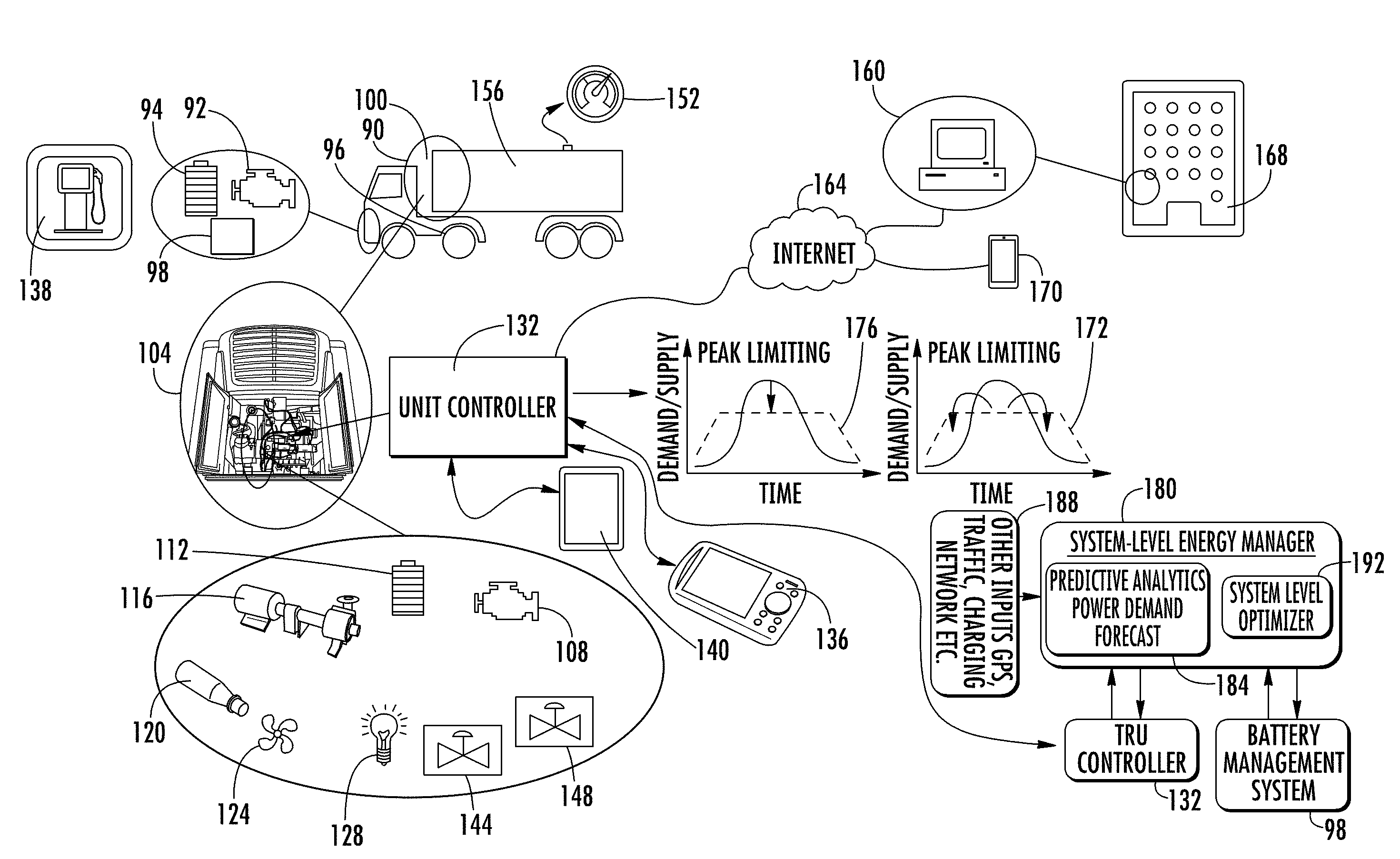
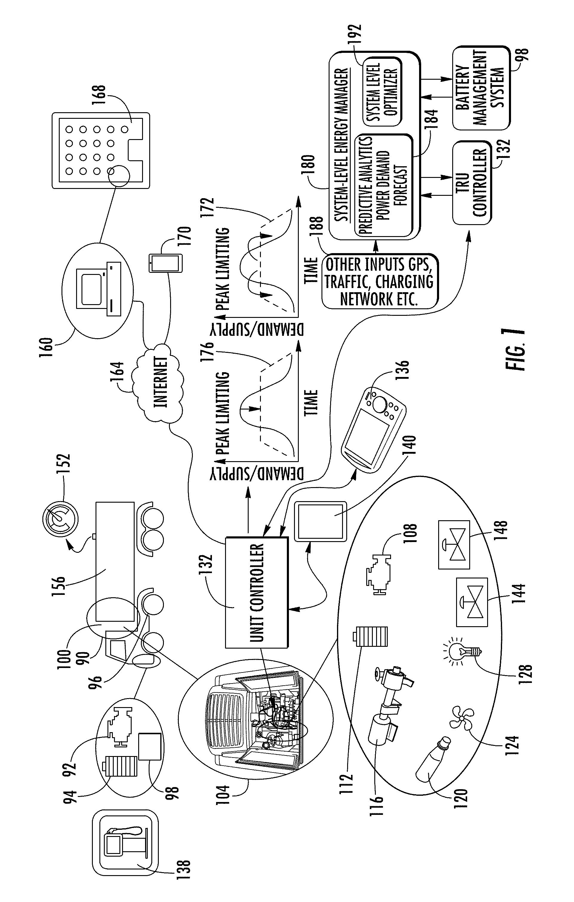
[0024] Turning to FIG. 1, the operational environment of an embodiment may include a trailer 100 having therein a transport refrigeration unit (TRU) 104. The trailer may be hauled by a tractor 90 having a plurality of power supply components. The plurality of trailer power supply components may include one or more of a motor 92, a battery 94 and a power regenerative axle 96. In addition the trailer may have a power controller 98 for controlling the plurality of trailer power supply components.
[0025] The TRU may include a plurality of TRU components, including a plurality of TRU power supply components and a plurality of power demand components. The TRU power supply components may include a TRU engine 108 and a TRU battery 112. The plurality of TRU power demand components may include a compressor 116 which may be a variable compressor. The TRU power demand components may further include an evaporator/condenser 120 with an associated fan 124. In addition, the power demand components may include cargo lights 128.
[0026] The plurality of TRU components may be dynamically controlled by a TRU electronics controller 132. The TRU controller may be onboard the TRU engine or may be a separate component in the TRU. The TRU controller may be capable of communicating with the trailer TRU power controller for controlling the use and distribution of power from the trailer power supply components.
[0027] The TRU controller may be equipped with a service providing dynamically updated Global Positioning Systems (GPS) data 136. Through the GPS the TRU controller may be able to identify best routes, a distance to a service station 138, and the like. It is to be appreciated that for an electrically powered TRU, the service station 138 would be connected to the electric grid. The TRU controller may include a visual interface 140. It is to be appreciate that the TRU controller is also a power sink. The TRU controller may control a plurality of cooling valves including an expansion valve 144 and a suction modulation valve 148.
[0028] In addition, the TRU controller may communicate with a cargo sensor 152 disposed in a cargo storage area 156. The cargo sensor may be, for example, a thermal sensor. The TRU controller may communicate with and be programmed by a central server 160 which may be a fleet central server that manages a fleet of such trailers. Such communications may occur via cellular or other wireless network 164 or a wired network determined at a fleet headquarters 168. Communications may also be with one or more cellular devices 170 in possession of the vehicle operator or maintenance personnel for diagnostic or other operational purposes.
[0029] Turning to FIG. 2, in one embodiment the TRU controller may manage demand-side energy requirements to extend the TRU operational range. The purpose of this process is to adaptively manage power requirements based on power availability, including when power is available and how much power is available. This process may be automatically initiated by the TRU controller. Alternatively, this process may be initiated in response to dynamic communications between the TRU controller and the fleet central server. Yet alternatively, this process may be initiated by the trailer operator via direct interaction with the TRU controller through the on board visual interface or using the mobile device. This decision process could include current and future predictions of energy available from dispatachable or non dispatchable sources such as solar.
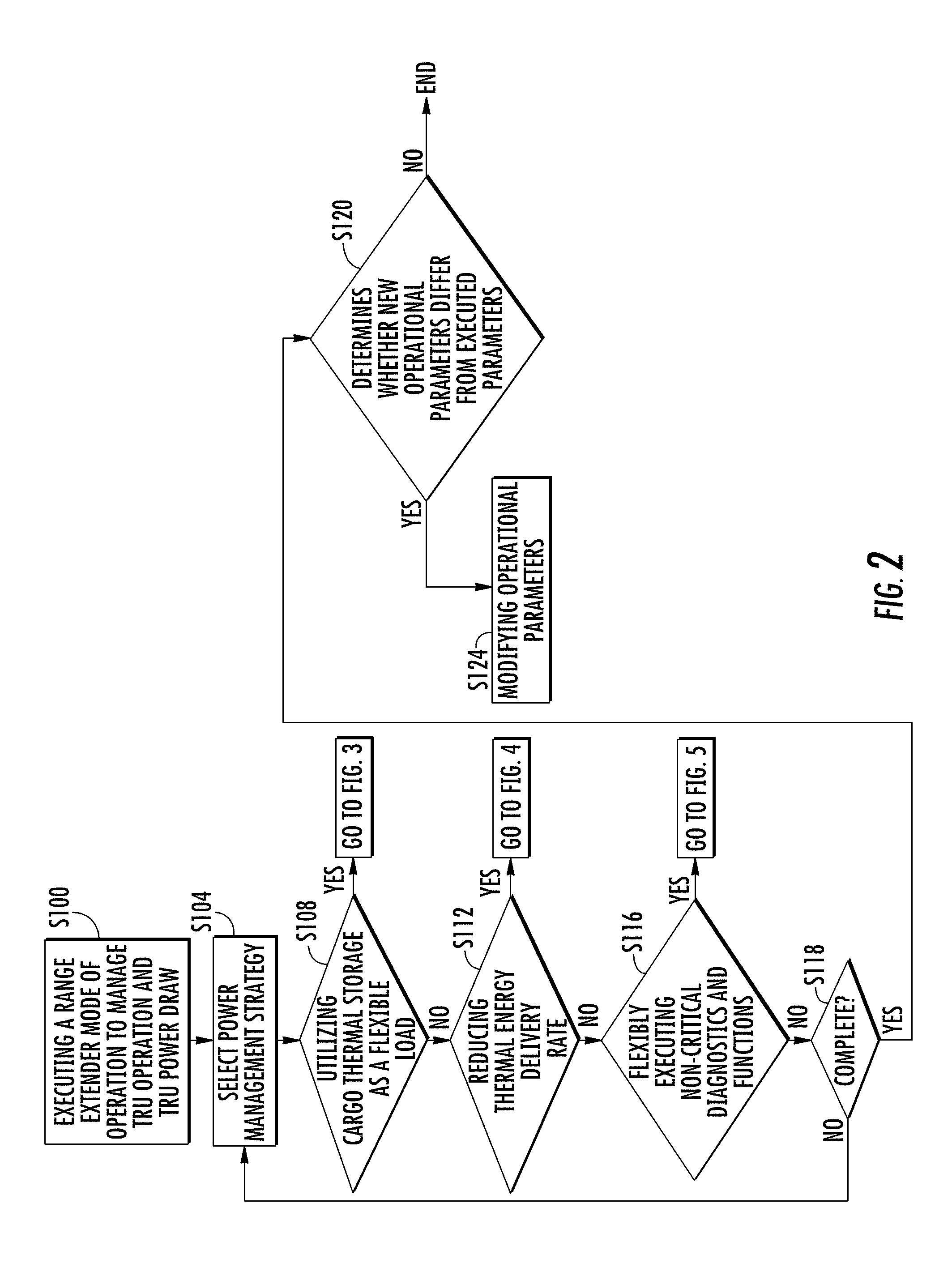
[0030] In managing the energy requirements of the TRU, the TRU controller may perform step S100 of executing a range extender mode of operation to manage TRU operation and power draw. In the range extender mode, the TRU configures a flexible TRU energy consumption management strategy by, for example, accounting for forecasts of required thermal load and specifics of the delivery mission.
[0031] At step S104, the TRU controller performs the step of selecting a power management strategy. At step S108, the TRU controller determines whether to select utilizing cargo thermal storage as a flexible load for the power management strategy, discussed in detail below. At step S112, the TRU controller determines whether to select reducing a thermal energy delivery rate for the power management strategy, discussed in detail below. At step S116, the TRU controller determines whether to select flexibly executing non-critical diagnostics and other functions for the power management strategy, discussed in detail below. The illustrated order of executing steps S108, S112 and 116 is not limiting. At step S118 the TRU controller determines whether the step S104 should be revisited or whether this part of the process is complete.
[0032] If the determination at step S118 is "yes" then the TRU controller performs step S120 of determining if step S100 is being executed during a transport mission and if the newly determined parameters differ from the currently executed parameters. If the determination of S120 is "yes" then the controller performs step S124 of modifying executed operational parameters for the TRU to provide improved load management for the remainder of the mission. If the determination of step S120 is "no" then no change in parameters is executed.
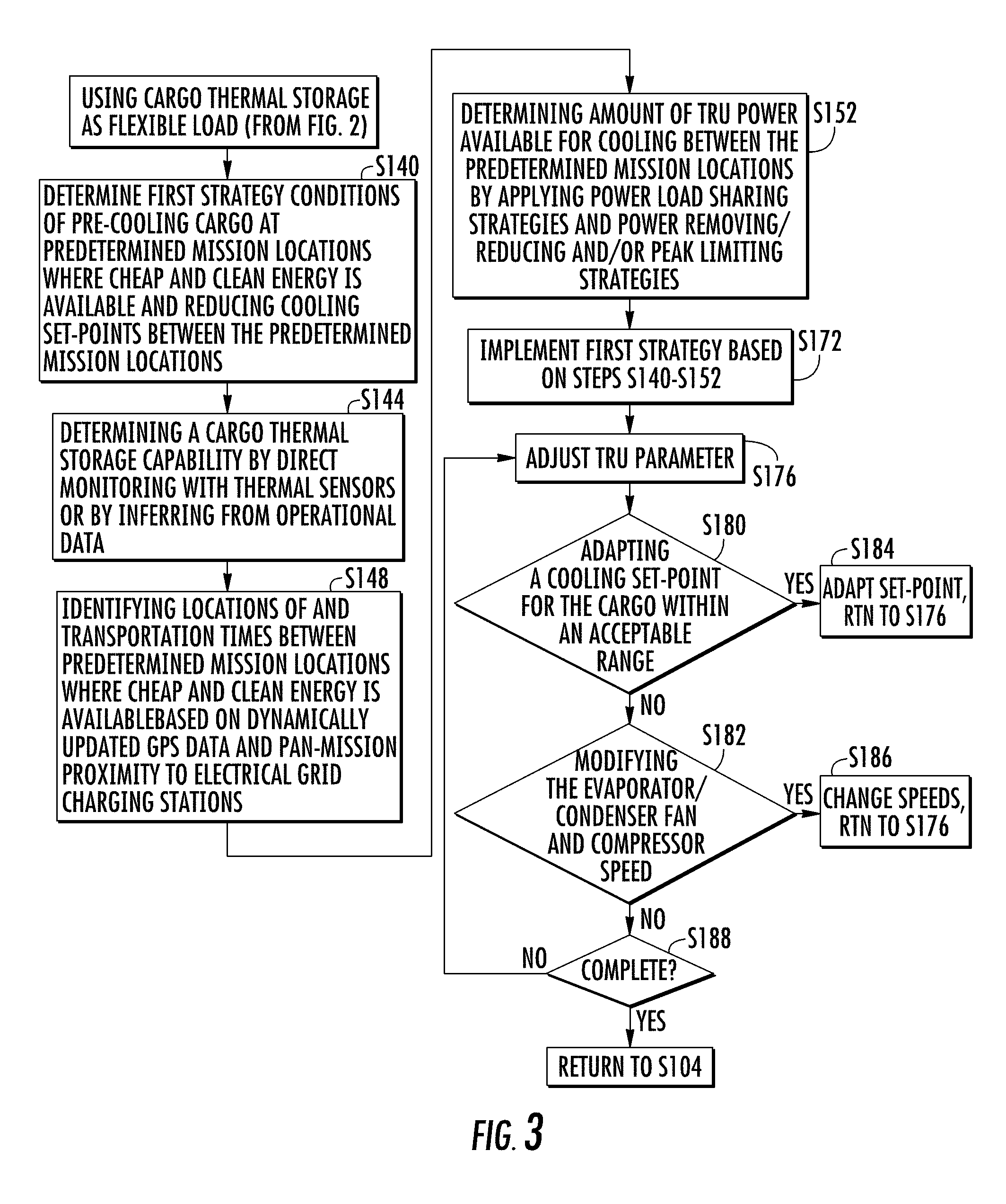
[0033] Turning to FIGS. 1, 2 and 3, if the TRU controller selected "yes" at step S108 then the TRU controller may perform step S140 of determining first strategy conditions of pre-cooling cargo at predetermined geographic mission locations where cheap and clean energy is available and reducing cooling set-points between the predetermined mission locations. At step S144 the TRU controller may determine a cargo thermal storage capability by direct monitoring with thermal sensors or by inferring from operational data. Cargo thermal storage refers to how much heat or cold cargo can store and this may be determined this by how much and how fast cargo loses stored energy. In the absence of a cargo sensor, including for example cargo space air temperature sensors, this can be inferred from the dynamics, for example rise time, of temperature in the storage area.
[0034] At step S148 the TRU controller may identify locations of and transportation times between predetermined mission locations where cheap and clean energy is available based on dynamically updated GPS data and pan-mission proximity to electrical grid charging stations. At step S152 the TRU controller may determine an amount of TRU power available for cooling between the predetermined mission locations by applying power load sharing strategies and power removing, reducing and/or peak limiting strategies. How much power the refrigeration unit will need (demand) is adjusted by modifying operating parameters, for example, changing actuator speeds and cooling set point.
[0035] At step S172 the TRU controller may implement the first strategy based on steps S140-S152. That is, the TRU controller may pre-cool the cargo or reduce cooling until, for example, grid power is available. For either of these options, the TRU controller may execute step S176 of selecting a TRU parameter to adjust. At step S180 the TRU controller may select adapting a cooling set-point for the cargo within an acceptable range for pre-cooling or reduced cooling based on the location in the mission. At step S182 the TRU controller may select modifying the evaporator and/or condenser fan speed and compressor speed for pre-cooling or reduced cooling based on the location in the mission.
[0036] A response of "yes" at step S180 may result in the TRU controller performing step S184 of adapting the cooling set-point while a response of "yes" at step S182 may result in the TRU controller performing step S186 of changing the fan speed and/or compressor speed. The illustrated order of executing steps S180 and S182 is not limiting and upon executing either of these steps the TRU controller returns to step S176. At step S188 the TRU controller may determine whether step S176 should be revisited or whether this part of the process is complete. A determination of "yes" at step S188 may proceed with the TRU controller returning to step S104.
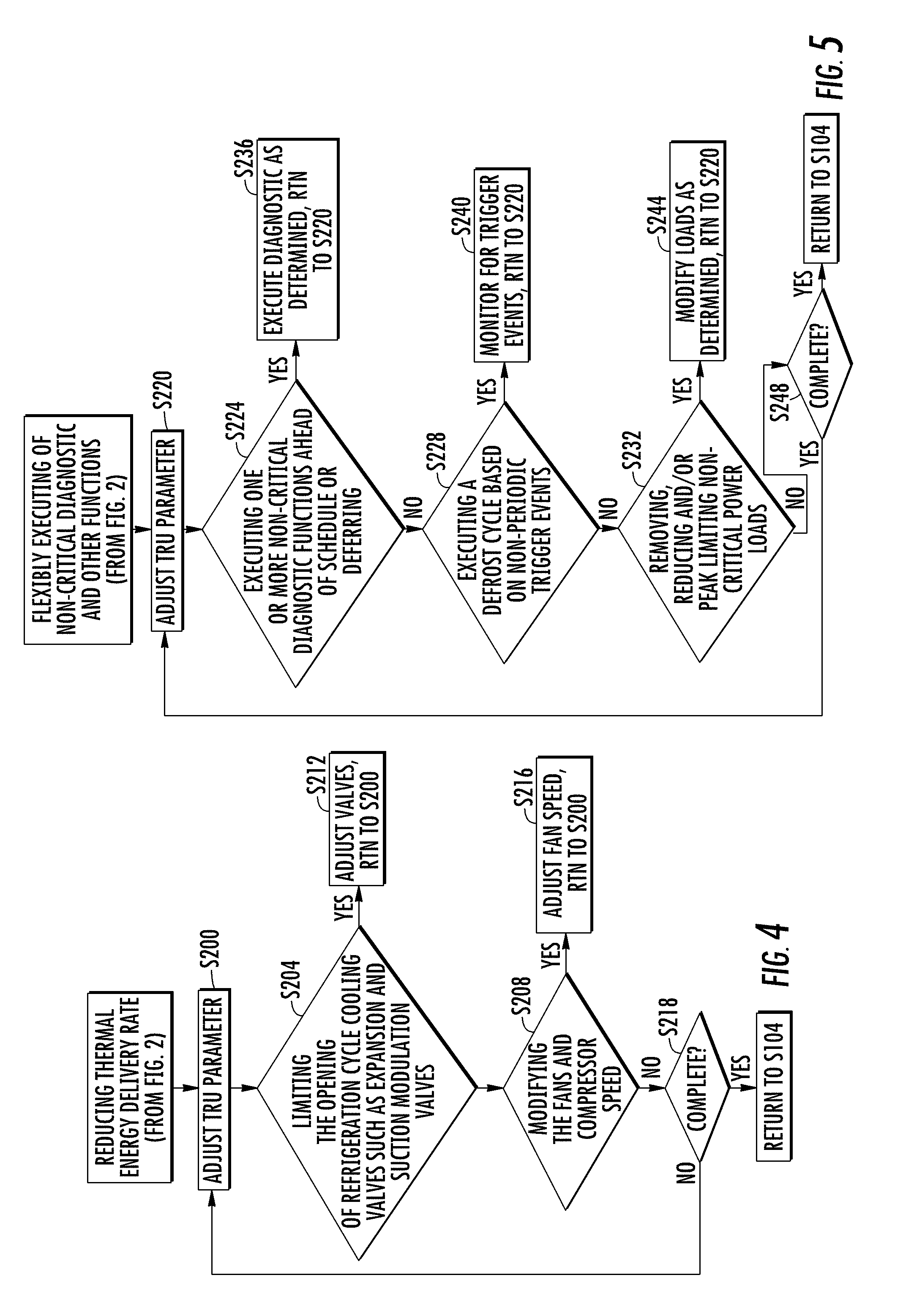
[0037] Turning to FIGS. 1, 2 and 4, if the TRU controller selected "yes" at step S112 then the TRU controller may perform step S200 of selecting a TRU parameter to adjust. At step S204 the TRU controller may select limiting the opening of refrigeration cycle cooling valves such as expansion and suction modulation valves. At step S208 the TRU controller may select modifying the evaporator/condenser fan speed and/or compressor speed. A response of "yes" at step S204 may result in the TRU controller performing step S212 of adjusting the valves. A response of "yes" at step S208 may result in the TRU controller performing step S216 of adjusting the fan speed and/or compressor speed. The illustrated order of executing steps S204 and S208 is not limiting and upon executing any of these steps the TRU controller returns to step S200. At step S218 the TRU controller determines whether step S220 should be revisited or whether this part of the process is complete. A determination of "yes" at step S218 proceeds with the TRU controller returning to step S104.
[0038] Turning to FIGS. 1, 2 and 5, if the TRU controller selected "yes" at step S116 then the TRU controller may perform step S220 of selecting a TRU parameter to adjust. Given the state of the TRU power availability, the TRU controller may perform step S224 of executing one or more non-critical diagnostic functions ahead of a predetermined schedule. At the same step the TRU controller may select deferring execution of such non-critical diagnostic functions until reaching a predetermined geographic mission location where energy is available, that is, a service station or a mission final destination. At step S228 the TRU controller may determine whether to execute a defrost cycle based on non-periodic trigger events rather a periodic approach. At step S232 the TRU controller may determine whether to remove/reduce/peak power limit or adapt non-critical loads such as light dimming and TRU controller display functions.
[0039] A response of "yes" at step S244 may result in the TRU controller performing step S236 of executing the diagnostic as determined, either ahead of the predetermined schedule or at the deferred time. A response of "yes" at step S228 may result in the TRU controller performing step S240 of monitoring for non-periodic trigger events before executing the defrost cycle. A response of "yes" at step S232 may result in the TRU controller performing step S244 of removing, reducing and/or peak limiting power loads as determined. The illustrated order of executing steps S236, S240 and S244 is not limiting and upon executing any of these steps the TRU controller returns to step S220. At step S248 the TRU controller determines whether step S220 should be revisited or whether this part of the process is complete. A determination of "yes" at step S248 proceeds with the TRU controller returning to step S104.
[0040] The above disclosed process may provide an ability to flexibly adjust load power consumption according to an available power supply and to make the TRU operations more resilient and robust to failures. The process may preserve a quality of transported goods during energy limiting conditions.
[0041] Turning now to FIGS. 1 and 6, instead of or in addition to executing the processes identified in FIGS. 2-5, when attempting to manage power systems in the trailer the TRU controller may perform step S260 of executing a first program 180 that functions as a system-level energy manager.
[0042] By executing the first program the TRU controller may perform step S264 of adaptively choosing energy flow parameters based on one or more mission specific parameters and TRU power health, such as state of battery charge and battery health. The mission specific parameters may include one or more of actual and forecasted in-route weather and traffic conditions, driver preferences, in-route proximity to an electrical grid charging station, loaded cargo type, cargo required temperature set-points and airflow, cargo current temperature and refrigeration cycle efficiency. For example, the loaded cargo type may be perishable or unperishable, cargo required temperature set-points are below or above freezing temperatures for loaded cargo, and driver preferences define a minimum duration of time between connecting to an electrical grid charging station. TRU power health includes an observed and a pan-mission anticipated state of TRU power supply components and power demand components. The refrigeration cycle efficiency may be learned from recorded trends/historical data related to the TRU operational mode, outside air temperature, altitude, and cooling/heating load. As a result of executing the first program, the TRU controller may make a holistic decision on how to better coordinate the operation of the TRU and the installed power supply options to meet the goal(s) of the delivery mission.
[0043] In one embodiment, by executing the first program, the TRU controller may perform step S272 of executing a first module 184 that is a predictive analytics module. By executing the first module the TRU controller may perform step S276 of collecting a first dataset of information 188 that is the mission specific information. With this collected dataset of information the TRU controller may perform step S280 of predicting the TRU's cooling power demand.
[0044] In one embodiment, by executing the first program, the TRU controller may perform step S284 of executing a second module 192 that is an online optimization module. By executing the second module, the TRU controller may execute step S288 of generating a power source schedule for the TRU based on the power demand for the specific loaded cargo determined in step S280.
[0045] In addition, by executing the second module, the TRU controller may perform step S288 of coordinating battery usage with the tractor power controller. By performing step S288 the TRU controller may perform step S292 of collecting a second dataset of information. The second dataset of information may include mission specific information for the tractor including predicted vehicle speed cycle. With the first dataset information and the second dataset of information, the TRU controller may perform step S292 of determining an availability of power take-off directly from tractor engine or through the regenerative axle on the tractor.
[0046] At step S296 the TRU controller may determine during a mission whether to re-execute the system-level energy manager. This step may include the TRU executing step S300 of determining whether to adjust a predetermined time interval based on updated mission specific conditions and TRU power health. If the determination at step S300 is "yes" then the TRU controller may perform step S304 of adjusting the period between executing the system-level energy manager. After adjusting the time at step S304, or if the determination at step S300 is "no", then the TRU controller may perform step S308 of determining whether the currently set time interval has elapsed. If the determination at step S308 is "no" then the TRU controller may cycle back to step S296. If the determination at step S308 is "yes" then the TRU controller may cycles back to step S260.
[0047] Using holistic information of the current and predicted behavior of the system to actively manage power flow and the battery operation may enable uninterrupted operation of the TRU while improving the operational efficiency of the integrated system. This approach may also (i) enable prioritization of cleaner energy for operation in urban areas with stricter emission and noise regulations, (ii) minimize fuel consumption and emissions for systems with installed range extenders, that is, with reduced sized engines, to ensure the TRU runs only when it is absolutely necessary, and (iii) minimize operational cost, for example, by optimizing grid charging during peak hour against fuel cost.
[0048] The term "about" is intended to include the degree of error associated with measurement of the particular quantity based upon the equipment available at the time of filing the application. The terminology used herein is for the purpose of describing particular embodiments only and is not intended to be limiting of the present disclosure. As used herein, the singular forms "a", "an" and "the" are intended to include the plural forms as well, unless the context clearly indicates otherwise. It will be further understood that the terms "comprises" and/or "comprising," when used in this specification, specify the presence of stated features, integers, steps, operations, elements, and/or components, but do not preclude the presence or addition of one or more other features, integers, steps, operations, element components, and/or groups thereof.
[0049] While the present disclosure has been described with reference to an exemplary embodiment or embodiments, it will be understood by those skilled in the art that various changes may be made and equivalents may be substituted for elements thereof without departing from the scope of the present disclosure. In addition, many modifications may be made to adapt a particular situation or material to the teachings of the present disclosure without departing from the essential scope thereof. Therefore, it is intended that the present disclosure not be limited to the particular embodiment disclosed as the best mode contemplated for carrying out this present disclosure, but that the present disclosure will include all embodiments falling within the scope of the claims.
* * * * *
D00000
D00001
D00002
D00003
D00004
D00005
XML
uspto.report is an independent third-party trademark research tool that is not affiliated, endorsed, or sponsored by the United States Patent and Trademark Office (USPTO) or any other governmental organization. The information provided by uspto.report is based on publicly available data at the time of writing and is intended for informational purposes only.
While we strive to provide accurate and up-to-date information, we do not guarantee the accuracy, completeness, reliability, or suitability of the information displayed on this site. The use of this site is at your own risk. Any reliance you place on such information is therefore strictly at your own risk.
All official trademark data, including owner information, should be verified by visiting the official USPTO website at www.uspto.gov. This site is not intended to replace professional legal advice and should not be used as a substitute for consulting with a legal professional who is knowledgeable about trademark law.