Expandable light guide for backlight
Dunn February 16, 2
U.S. patent number 10,921,510 [Application Number 16/259,921] was granted by the patent office on 2021-02-16 for expandable light guide for backlight. This patent grant is currently assigned to Manufacturing Resources International, Inc.. The grantee listed for this patent is Manufacturing Resources International, Inc.. Invention is credited to William Dunn.


| United States Patent | 10,921,510 |
| Dunn | February 16, 2021 |
Expandable light guide for backlight
Abstract
Described herein are exemplary embodiments of a light guide assembly for a backlight and backlight assemblies using such light guide assemblies. An exemplary backlight assembly may have a light guide with a pair of opposing edges and a sliding LED subassembly placed along an edge of the light guide and attached to the light guide so that movement of the light guide causes movement of the sliding LED subassembly. In some embodiments, a first slot may be positioned within the light guide where a post extends from the sliding LED subassembly to engage with the first slot in the light guide. In some embodiments, a back pan may be positioned behind the light guide where a post can extend from the back pan to engage with a second slot in the light guide.
| Inventors: | Dunn; William (Alpharetta, GA) | ||||||||||
|---|---|---|---|---|---|---|---|---|---|---|---|
| Applicant: |
|
||||||||||
| Assignee: | Manufacturing Resources
International, Inc. (Alpharetta, GA) |
||||||||||
| Family ID: | 53265168 | ||||||||||
| Appl. No.: | 16/259,921 | ||||||||||
| Filed: | January 28, 2019 |
Prior Publication Data
| Document Identifier | Publication Date | |
|---|---|---|
| US 20190154909 A1 | May 23, 2019 | |
Related U.S. Patent Documents
| Application Number | Filing Date | Patent Number | Issue Date | ||
|---|---|---|---|---|---|
| 14558326 | Dec 2, 2014 | 10191212 | |||
| 61910568 | Dec 2, 2013 | ||||
| Current U.S. Class: | 1/1 |
| Current CPC Class: | G02B 6/0091 (20130101); G02F 1/133615 (20130101) |
| Current International Class: | F21V 8/00 (20060101); G02F 1/13357 (20060101) |
| Field of Search: | ;362/600-634 |
References Cited [Referenced By]
U.S. Patent Documents
| 1812919 | July 1931 | Balder |
| 3510973 | May 1970 | Mazzocco, Sr. |
| 4257084 | March 1981 | Reynolds |
| 4804953 | February 1989 | Castleberry |
| 5040878 | August 1991 | Eichenlaub |
| 5046805 | September 1991 | Simon |
| 5066106 | November 1991 | Sakamoto et al. |
| 5363149 | November 1994 | Furuno et al. |
| 5365354 | November 1994 | Jannson et al. |
| 5381309 | January 1995 | Borchardt |
| 5440324 | August 1995 | Strickling, III et al. |
| 5453855 | September 1995 | Nakamura et al. |
| 5528720 | June 1996 | Winston et al. |
| 5598068 | January 1997 | Shirai |
| 5661578 | August 1997 | Habing et al. |
| 5856854 | January 1999 | Hyun |
| 6027222 | February 2000 | Oki et al. |
| 6166389 | December 2000 | Shie et al. |
| 6307216 | October 2001 | Huh et al. |
| 6400101 | June 2002 | Biebl et al. |
| 6409356 | June 2002 | Nishimura |
| 6419372 | July 2002 | Shaw et al. |
| 6421103 | July 2002 | Yamaguchi |
| 6437673 | August 2002 | Nishida et al. |
| 6446467 | September 2002 | Lieberman et al. |
| 6481130 | November 2002 | Wu |
| 6556258 | April 2003 | Yoshida et al. |
| 6601984 | August 2003 | Yamamoto et al. |
| 6636003 | October 2003 | Rahm et al. |
| 6683639 | January 2004 | Driessen-Olde Scheper et al. |
| 6762815 | July 2004 | Lee |
| 6789921 | September 2004 | Deloy et al. |
| 6805468 | October 2004 | Itoh et al. |
| 6842204 | January 2005 | Johnson |
| 6860628 | March 2005 | Robertson et al. |
| 6936968 | August 2005 | Cross et al. |
| 6949772 | September 2005 | Shimizu et al. |
| 6958743 | October 2005 | Shin et al. |
| 6982686 | January 2006 | Miyachi et al. |
| 7012379 | March 2006 | Chambers et al. |
| 7015650 | March 2006 | McGrath |
| 7018054 | March 2006 | Miyashita et al. |
| 7025474 | April 2006 | Campbell et al. |
| 7038186 | May 2006 | De Brabander et al. |
| 7040794 | May 2006 | Bernard |
| 7045828 | May 2006 | Shimizu et al. |
| 7049761 | May 2006 | Timmermans et al. |
| 7053557 | May 2006 | Cross et al. |
| 7057590 | June 2006 | Lim et al. |
| 7178963 | February 2007 | Ueda et al. |
| 7190416 | March 2007 | Paukshto et al. |
| 7194158 | March 2007 | Schultheis et al. |
| 7210839 | May 2007 | Jung et al. |
| 7218812 | May 2007 | Maxwell et al. |
| 7232250 | June 2007 | Chuang |
| 7250637 | July 2007 | Shimizu et al. |
| 7259403 | August 2007 | Shimizu et al. |
| 7307391 | December 2007 | Shan |
| 7307614 | December 2007 | Vinn |
| 7324080 | January 2008 | Hu et al. |
| 7327416 | February 2008 | Lee et al. |
| 7347706 | March 2008 | Wu et al. |
| 7352940 | April 2008 | Charters et al. |
| 7375381 | May 2008 | Shimizu et al. |
| 7421167 | September 2008 | Charters et al. |
| 7427140 | September 2008 | Ma |
| 7473019 | January 2009 | Laski |
| 7481553 | January 2009 | Kim et al. |
| 7481566 | January 2009 | Han |
| 7510299 | March 2009 | Timmermans et al. |
| 7513637 | April 2009 | Kelly et al. |
| 7542108 | June 2009 | Saito et al. |
| 7546009 | June 2009 | Kukulj et al. |
| 7682047 | March 2010 | Hsu et al. |
| 7738746 | June 2010 | Charters et al. |
| 7781979 | August 2010 | Lys |
| 7795574 | September 2010 | Kennedy et al. |
| 7813694 | October 2010 | Fishman et al. |
| 7853288 | December 2010 | Ma |
| 7982706 | July 2011 | Ichikawa et al. |
| 8021900 | September 2011 | Maxwell et al. |
| 8064744 | November 2011 | Atkins et al. |
| 8120595 | February 2012 | Kukulj et al. |
| 8125163 | February 2012 | Dunn et al. |
| 8194031 | June 2012 | Yao et al. |
| 8233115 | July 2012 | Hadlich et al. |
| 8274626 | September 2012 | Choi et al. |
| 8294168 | October 2012 | Park et al. |
| 8351013 | January 2013 | Dunn et al. |
| 8400430 | March 2013 | Dunn et al. |
| 8508155 | August 2013 | Schuch |
| 8529993 | September 2013 | Charters et al. |
| 8648993 | February 2014 | Dunn et al. |
| 8674390 | March 2014 | Harris et al. |
| 8674963 | March 2014 | Cornish et al. |
| 8803790 | August 2014 | Wasinger et al. |
| 8829815 | September 2014 | Dunn et al. |
| 8842366 | September 2014 | Arnett et al. |
| 9030129 | May 2015 | Dunn et al. |
| 9167655 | October 2015 | Dunn et al. |
| 9348174 | May 2016 | Dunn et al. |
| 9812047 | November 2017 | Schuch et al. |
| 9867253 | January 2018 | Dunn et al. |
| 9924583 | March 2018 | Schuch et al. |
| 10126579 | November 2018 | Dunn et al. |
| 10191212 | January 2019 | Dunn |
| 2001/0009508 | July 2001 | Umemoto et al. |
| 2001/0033726 | October 2001 | Shie et al. |
| 2002/0043012 | April 2002 | Shibata et al. |
| 2002/0126078 | September 2002 | Horibe et al. |
| 2003/0026085 | February 2003 | Ueda et al. |
| 2003/0043312 | March 2003 | Nishida et al. |
| 2003/0227428 | December 2003 | Nose |
| 2004/0062029 | April 2004 | Ato |
| 2004/0113044 | June 2004 | Ishiguchi |
| 2005/0094391 | May 2005 | Campbell et al. |
| 2005/0105303 | May 2005 | Emde |
| 2005/0117323 | June 2005 | King |
| 2005/0140848 | June 2005 | Yoo et al. |
| 2005/0162737 | July 2005 | Whitehead et al. |
| 2005/0265019 | December 2005 | Sommers et al. |
| 2006/0012985 | January 2006 | Archie, Jr. et al. |
| 2006/0055012 | March 2006 | Hsin Chen et al. |
| 2006/0072299 | April 2006 | Lai |
| 2006/0077686 | April 2006 | Han et al. |
| 2006/0082700 | April 2006 | Gehlsen et al. |
| 2006/0087521 | April 2006 | Chu et al. |
| 2006/0092346 | May 2006 | Moon et al. |
| 2006/0092348 | May 2006 | Park |
| 2006/0125418 | June 2006 | Bourgault |
| 2006/0197474 | September 2006 | Olsen |
| 2006/0221612 | October 2006 | Song et al. |
| 2006/0238367 | October 2006 | Tsuchiya |
| 2006/0262079 | November 2006 | Seong et al. |
| 2006/0279946 | December 2006 | Park et al. |
| 2006/0289201 | December 2006 | Kim et al. |
| 2007/0013647 | January 2007 | Lee et al. |
| 2007/0013828 | January 2007 | Cho et al. |
| 2007/0021217 | January 2007 | Wu |
| 2007/0070615 | March 2007 | Joslin et al. |
| 2007/0097321 | May 2007 | Whitehead et al. |
| 2007/0115686 | May 2007 | Tyberghien |
| 2007/0127144 | June 2007 | Gao |
| 2007/0139574 | June 2007 | Ko et al. |
| 2007/0139929 | June 2007 | Yoo et al. |
| 2007/0147037 | June 2007 | Wang |
| 2007/0153515 | July 2007 | Hong et al. |
| 2007/0171353 | July 2007 | Hong |
| 2007/0171623 | July 2007 | Zagar et al. |
| 2007/0171676 | July 2007 | Chang |
| 2007/0177071 | August 2007 | Egi et al. |
| 2007/0195535 | August 2007 | Artwohl et al. |
| 2007/0198638 | August 2007 | Omura et al. |
| 2007/0206158 | September 2007 | Kinoshita et al. |
| 2007/0222910 | September 2007 | Hu |
| 2007/0230218 | October 2007 | Jachim et al. |
| 2007/0268234 | November 2007 | Wakabayashi et al. |
| 2007/0297163 | December 2007 | Kim et al. |
| 2007/0297172 | December 2007 | Furukawa et al. |
| 2008/0019147 | January 2008 | Erchak et al. |
| 2008/0036940 | February 2008 | Song et al. |
| 2008/0043463 | February 2008 | Park et al. |
| 2008/0049164 | February 2008 | Jeon et al. |
| 2008/0068836 | March 2008 | Hatanaka et al. |
| 2008/0089064 | April 2008 | Wang |
| 2008/0101086 | May 2008 | Lee |
| 2008/0106527 | May 2008 | Cornish et al. |
| 2008/0111949 | May 2008 | Shibata et al. |
| 2008/0143916 | June 2008 | Fujino et al. |
| 2008/0151527 | June 2008 | Ueno et al. |
| 2008/0170178 | July 2008 | Kubota et al. |
| 2008/0170400 | July 2008 | Maruyama |
| 2008/0212305 | September 2008 | Kawana et al. |
| 2008/0231196 | September 2008 | Weng et al. |
| 2008/0276507 | November 2008 | Hines |
| 2008/0284942 | November 2008 | Mahama et al. |
| 2009/0002990 | January 2009 | Becker et al. |
| 2009/0009102 | January 2009 | Kahlman et al. |
| 2009/0015755 | January 2009 | Bang et al. |
| 2009/0021461 | January 2009 | Hu et al. |
| 2009/0033612 | February 2009 | Roberts et al. |
| 2009/0058795 | March 2009 | Yamazaki |
| 2009/0061945 | March 2009 | Ma |
| 2009/0085859 | April 2009 | Song |
| 2009/0091634 | April 2009 | Kennedy et al. |
| 2009/0109165 | April 2009 | Park et al. |
| 2009/0135167 | May 2009 | Sakai et al. |
| 2009/0135583 | May 2009 | Hillman et al. |
| 2009/0174840 | July 2009 | Lee et al. |
| 2009/0196069 | August 2009 | Iwasaki |
| 2009/0243501 | October 2009 | Dunn et al. |
| 2009/0244884 | October 2009 | Trulaske, Sr. |
| 2009/0284457 | November 2009 | Botzas et al. |
| 2009/0289580 | November 2009 | Dunn et al. |
| 2010/0039440 | February 2010 | Tanaka et al. |
| 2010/0102735 | April 2010 | Chang et al. |
| 2010/0109553 | May 2010 | Chang et al. |
| 2010/0165240 | July 2010 | Cho et al. |
| 2010/0194296 | August 2010 | Park |
| 2010/0220258 | September 2010 | Dunn et al. |
| 2010/0231563 | September 2010 | Dunn et al. |
| 2010/0307800 | December 2010 | Wee et al. |
| 2010/0313592 | December 2010 | Pae |
| 2011/0007228 | January 2011 | Yoon et al. |
| 2011/0013114 | January 2011 | Dunn et al. |
| 2011/0083460 | April 2011 | Thomas et al. |
| 2011/0102704 | May 2011 | Dunn et al. |
| 2011/0116000 | May 2011 | Dunn et al. |
| 2011/0141724 | June 2011 | Erion |
| 2011/0164434 | July 2011 | Derichs |
| 2011/0205145 | August 2011 | Lin et al. |
| 2011/0242437 | October 2011 | Yoo et al. |
| 2011/0242839 | October 2011 | Dunn et al. |
| 2011/0283199 | November 2011 | Schuch et al. |
| 2012/0050958 | March 2012 | Sanford et al. |
| 2012/0062819 | March 2012 | Dunn et al. |
| 2012/0086344 | April 2012 | Schuch |
| 2012/0098794 | April 2012 | Kleinert et al. |
| 2012/0105424 | May 2012 | Lee et al. |
| 2012/0134139 | May 2012 | Jang et al. |
| 2012/0154712 | June 2012 | Yu et al. |
| 2012/0212520 | August 2012 | Matsui et al. |
| 2012/0212956 | August 2012 | Chen |
| 2012/0242926 | September 2012 | Hsu et al. |
| 2012/0250329 | October 2012 | Suehiro et al. |
| 2012/0274882 | November 2012 | Jung |
| 2012/0299891 | November 2012 | Fujiwara et al. |
| 2012/0314447 | December 2012 | Huang |
| 2012/0327039 | December 2012 | Kukulj |
| 2013/0016080 | January 2013 | Dunn et al. |
| 2013/0016296 | January 2013 | Fujita et al. |
| 2013/0027633 | January 2013 | Park et al. |
| 2013/0063326 | March 2013 | Riegel |
| 2013/0094160 | April 2013 | Narumi |
| 2013/0163277 | June 2013 | Kim et al. |
| 2013/0258659 | October 2013 | Erion |
| 2013/0278868 | October 2013 | Dunn et al. |
| 2014/0016355 | January 2014 | Ajichi |
| 2014/0078407 | March 2014 | Green et al. |
| 2014/0085564 | March 2014 | Hendren et al. |
| 2014/0104538 | April 2014 | Park et al. |
| 2014/0134767 | May 2014 | Ishida et al. |
| 2014/0144083 | May 2014 | Artwohl et al. |
| 2014/0268657 | September 2014 | Dunn et al. |
| 2014/0285477 | September 2014 | Cho et al. |
| 2014/0340375 | November 2014 | Dunn et al. |
| 2014/0361969 | December 2014 | Wasinger et al. |
| 2015/0009653 | January 2015 | Dunn et al. |
| 2015/0153506 | June 2015 | Dunn |
| 2015/0219954 | August 2015 | Kubo |
| 2015/0226996 | August 2015 | Ohashi |
| 2015/0245443 | August 2015 | Dunn et al. |
| 2015/0247968 | September 2015 | Verrat-Debailleul et al. |
| 2015/0346525 | December 2015 | Wolf et al. |
| 2016/0037606 | February 2016 | Dunn et al. |
| 2016/0103275 | April 2016 | Diaz et al. |
| 2016/0238876 | August 2016 | Dunn et al. |
| 2016/0334666 | November 2016 | Liu |
| 2016/0335705 | November 2016 | Williams et al. |
| 2016/0338181 | November 2016 | Schuch et al. |
| 2016/0338182 | November 2016 | Schuch et al. |
| 2016/0351133 | December 2016 | Kim et al. |
| 2016/0358538 | December 2016 | Schuch et al. |
| 2017/0059938 | March 2017 | Brown et al. |
| 2017/0248823 | August 2017 | Dunn et al. |
| 2018/0012566 | January 2018 | Lin et al. |
| 2018/0048849 | February 2018 | Dunn |
| 2018/0061297 | March 2018 | Schuch et al. |
| 2004283319 | May 2005 | AU | |||
| 2007216782 | Sep 2007 | AU | |||
| 2536130 | May 2005 | CA | |||
| 2688214 | Nov 2008 | CA | |||
| 1836179 | Sep 2006 | CN | |||
| 101432647 | May 2007 | CN | |||
| 101048685 | Oct 2007 | CN | |||
| 101339272 | Jan 2009 | CN | |||
| 101351765 | Jan 2009 | CN | |||
| 101681222 | Mar 2010 | CN | |||
| 0313331 | Apr 1989 | EP | |||
| 1678534 | Jul 2006 | EP | |||
| 1805539 | Jul 2007 | EP | |||
| 2156276 | May 2008 | EP | |||
| 1941342 | Jul 2008 | EP | |||
| 153110 | Nov 1920 | GB | |||
| 30/2007 | Feb 2006 | IN | |||
| 03/2009 | May 2008 | IN | |||
| 15/2010 | Dec 2009 | IN | |||
| 11095214 | Apr 1999 | JP | |||
| 2002064842 | Feb 2002 | JP | |||
| 2002209230 | Jul 2002 | JP | |||
| 2004004581 | Jan 2004 | JP | |||
| 2007509372 | Oct 2004 | JP | |||
| 2004325629 | Nov 2004 | JP | |||
| 2005228996 | Aug 2005 | JP | |||
| 2005236469 | Sep 2005 | JP | |||
| 2005-292939 | Oct 2005 | JP | |||
| 2008518251 | Oct 2005 | JP | |||
| 2005-332253 | Dec 2005 | JP | |||
| 2006-198344 | Aug 2006 | JP | |||
| 2007080872 | Mar 2007 | JP | |||
| 2009535723 | May 2007 | JP | |||
| 200876755 | Apr 2008 | JP | |||
| 2008112719 | May 2008 | JP | |||
| 2008256819 | Oct 2008 | JP | |||
| 2009036964 | Feb 2009 | JP | |||
| 2009512898 | Mar 2009 | JP | |||
| 2009231473 | Oct 2009 | JP | |||
| 2010509622 | Mar 2010 | JP | |||
| 2010527100 | Aug 2010 | JP | |||
| 2010282109 | Dec 2010 | JP | |||
| 2011081424 | Apr 2011 | JP | |||
| 2014-71343 | Apr 2014 | JP | |||
| 20-0286961 | Aug 2002 | KR | |||
| 1020070003755 | Feb 2006 | KR | |||
| 20070005637 | Jan 2007 | KR | |||
| 1020070084554 | May 2007 | KR | |||
| 20080013592 | Feb 2008 | KR | |||
| 20080063414 | Jul 2008 | KR | |||
| 20080074972 | Aug 2008 | KR | |||
| 1020090007776 | Jan 2009 | KR | |||
| 20100019997 | Feb 2010 | KR | |||
| 1020050033986 | Apr 2014 | KR | |||
| 101796718 | Nov 2017 | KR | |||
| 200615598 | May 2006 | TW | |||
| 200802054 | Jan 2008 | TW | |||
| 200808925 | Feb 2008 | TW | |||
| 200809285 | Feb 2008 | TW | |||
| 200809287 | Feb 2008 | TW | |||
| 200828093 | Jul 2008 | TW | |||
| 200912200 | Mar 2009 | TW | |||
| 201030376 | Aug 2010 | TW | |||
| 201038114 | Oct 2010 | TW | |||
| WO9608892 | Mar 1996 | WO | |||
| WO2005051054 | Jun 2005 | WO | |||
| WO2005093703 | Oct 2005 | WO | |||
| WO2006001559 | Jan 2006 | WO | |||
| WO2006109237 | Oct 2006 | WO | |||
| WO2007052777 | May 2007 | WO | |||
| WO2005040873 | May 2008 | WO | |||
| WO2008138049 | Nov 2008 | WO | |||
| WO2008152832 | Dec 2008 | WO | |||
| WO2009004574 | Jan 2009 | WO | |||
| WO2010080624 | Jul 2010 | WO | |||
| WO2010129271 | Nov 2010 | WO | |||
| WO2011100429 | Aug 2011 | WO | |||
| WO2011143719 | Nov 2011 | WO | |||
| WO-2014034546 | Mar 2014 | WO | |||
| WO2014158642 | Oct 2014 | WO | |||
| WO2015003130 | Jan 2015 | WO | |||
| WO2018031753 | Feb 2018 | WO | |||
Other References
|
Wikipedia, Gradient-index optics, 2016. cited by applicant . Patrick Frantz & Dean Ia Fernandez, Printed Circuit Boards (PCBs), Feb. 18, 2004, 2 Pages, Version 1.1. cited by applicant . Teravision Corp., LCD-TV Panel Control Board Specification, Nov. 2007, 24 Pages. cited by applicant . Supertex Inc., Constant Off-time, Buck-based LED Drivers Using HV9910, Nov. 2, 2004, 4 Pages. cited by applicant . Grin Tech, Grin Lenses, Aug. 25, 2016, 4 Pages. cited by applicant . Supertex Inc., Universal High Brightness LED Driver, 2007, 8 Pages. cited by applicant . Shigeru Aoyama, Akihiro Funamoto & Koichi Imanaka, Hybrid normal-reverse prism coupler for light-emitting diode backlight systems, Oct. 1, 2006, 6 Pages, vol. 45, No. 28. cited by applicant . Panel-Brite, Inc., High Brightness LED Backlight Technology, Mar. 11, 2009, 1 Page. cited by applicant . RPO, How Digital Waveguide Touch Works, Sep. 15, 2011, 1 Page. cited by applicant . Dave Roos, How Transmissive Film Works, article, 2008, 9 pages. cited by applicant . Schott, Glass made of Ideas--OPALIKA, 2016, 2 pages. cited by applicant . Anandan, LED Backlight: Enhancement of picture quality on LCD screen, Oct. 8-12, 2006, 5 pages. cited by applicant . Lu, Color shift reduction of a multi-domain IPS-LCD using RGB-LED backlight, 2006, 10 pages. cited by applicant . Anandan, M., Progress of LED backlights for LCDs, Journal of the SID, 2008, pp. 287-310, 16/2. cited by applicant. |
Primary Examiner: Carter; William J
Attorney, Agent or Firm: Standley Law Group LLP Standley; Jeffrey S. Gayan; Eric M.
Parent Case Text
CROSS-REFERENCE TO RELATED APPLICATIONS
This application is a continuation of U.S. patent application Ser. No. 14/558,326 filed on Dec. 2, 2014, which claims the benefit of U.S. Provisional Application No. 61/910,568 filed on Dec. 2, 2013, each of which are herein incorporated by reference in their entirety.
Claims
What is claimed is:
1. A light guide assembly for a backlight, comprising: a planar light guide having first and second opposing edges to be illuminated; a plurality of slots in the light guide, each slot having a length that extends parallel to the first and second opposing edges of the light guide; a planar light guide spacer residing rearward of the light guide and associated with the first and second opposing edges of the light guide; a back pan residing rearward of the light guide spacer; first and second L-shaped LED connecting assemblies, each LED connecting assembly having a connecting portion that resides rearward of the light guide and is coupled to the light guide spacer, and a LED mounting portion that extends transversely from the light guide connecting portion to reside adjacent to and parallel with a respective one of the opposing edges of the light guide when the LED connecting assemblies are coupled thereto; and a plurality of slots through the back pan, the slots having a length that extends perpendicular to the slots in the light guide and arranged to receive a portion of posts that couple the light guide spacer to the connecting portions of the LED connecting assemblies; whereby the light guide spacer and the LED connecting assemblies are constrained to move in kind with the light guide during thermal expansion or contraction of the light guide in a direction perpendicular to the length of the slots in the light guide.
2. The light guide assembly of claim 1, wherein the light guide is freely movable relative to the light guide spacer and the LED connecting assemblies in a direction parallel to the length of the slots in the light guide.
3. The light guide assembly of claim 1, wherein the light guide spacer further includes a plurality of coupling elements that extend therefrom into corresponding ones of the slots in the light guide.
4. The light guide assembly of claim 1, wherein the LED mounting portions of the first and second LED connecting assemblies reside at a predetermined, fixed distance from the respective first and second opposing edges edge of the light guide.
5. The light guide assembly of claim 1, further comprising a set of LEDs affixed to the LED mounting portion of each of the LED connecting assemblies.
6. The light guide assembly of claim 5, wherein each set of LEDs is mounted to the LED mounting portion of its respective LED connecting assembly with a substrate therebetween.
7. A light guide assembly for a backlight, comprising: a planar light guide having first and second opposing edges to be illuminated; a plurality of slots in the light guide, each slot having a length that extends parallel to the first and second opposing edges of the light guide; first and second planar light guide spacers residing rearward of the light guide and respectively associated with the first and second opposing edges of the light guide; a back pan residing rearward of the light guide spacers; first and second L-shaped LED connecting assemblies, each LED connecting assembly having a connecting portion that resides rearward of the light guide and is coupled to a respective one of the light guide spacers, and a LED mounting portion that extends transversely from the light guide connecting portion to reside adjacent to and parallel with a respective one of the opposing edges of the light guide when the LED connecting assemblies are coupled thereto; and a plurality of slots through the back pan, the slots having a length that extends perpendicular to the slots in the light guide and arranged to receive a portion of posts that couple each light guide spacer to the connecting portion of a respective one of the LED connecting assemblies; whereby the light guide spacers and the LED connecting assemblies are constrained to move in kind with the light guide during thermal expansion or contraction of the light guide in a direction perpendicular to the length of the slots in the light guide.
8. The light guide assembly of claim 7, wherein the light guide is freely movable relative to the light guide spacers and the LED connecting assemblies in a direction parallel to the length of the slots in the light guide.
9. The light guide assembly of claim 7, wherein each light guide spacer further includes a plurality of coupling elements that extend therefrom into corresponding ones of the slots in the light guide.
10. The light guide assembly of claim 7, wherein the LED mounting portions of the first and second LED connecting assemblies reside at a predetermined, fixed distance from the respective first and second opposing edges edge of the light guide.
11. The light guide assembly of claim 7, further comprising a set of LEDs affixed to the LED mounting portion of each of the LED connecting assemblies.
12. The light guide assembly of claim 11, wherein each set of LEDs is mounted to the LED mounting portion of its respective LED connecting assembly with a substrate therebetween.
Description
TECHNICAL FIELD
Embodiments described herein generally relate to light guides that are configured to account for thermal expansion/contraction and backlight assemblies utilizing such light guides.
BACKGROUND OF THE ART
Backlit displays are used in a number of applications including advertising, entertainment, or informational applications. They are also used in a number of different operating environments including outdoors, direct sunlight, or other applications which may have warm or cool ambient temperatures surrounding the display. Most backlights utilize some form of light guide, which is commonly made of materials which may be affected by changes in temperature. Thermal expansion or contraction of the light guide can cause both mechanical and optical defects in the display.
SUMMARY OF THE EXEMPLARY EMBODIMENTS
Exemplary embodiments provide a backlight assembly where the light guide is permitted to expand and contract without substantially changing the distance between the LEDs and the light guide. A first set of slots may be placed in the light guide and a second set of slots are preferably positioned on the opposite side of the light guide and parallel to the first set of slots. The first set of slots may engage with a post which extends from the back pan. The second set of slots may contain a post which extends from a sliding LED subassembly. The sliding LED subassembly is preferably connected with the light guide so that the LEDs within the subassembly can move with the light guide.
The foregoing and other features and advantages of the present invention will be apparent from the following more detailed description of the particular embodiments, as illustrated in the accompanying drawings.
BRIEF DESCRIPTION OF THE DRAWINGS
A better understanding of an exemplary embodiment will be obtained from a reading of the following detailed description and the accompanying drawings wherein identical reference characters refer to identical parts and in which:
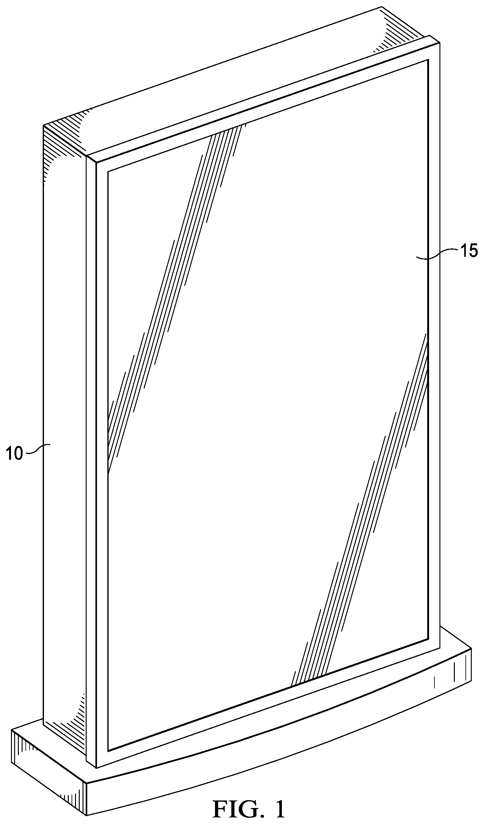
FIG. 1 is a front perspective view of a backlit display.
FIG. 2 is an exploded view of an edge-lit backlight assembly.
FIG. 3 is a side planar view of the edge-lit backlight assembly shown in FIG. 2 where the advertising poster or LCD stack has been removed.
FIG. 4 is a front planar view of the relative positioning of the LEDs in relation to the light guide.
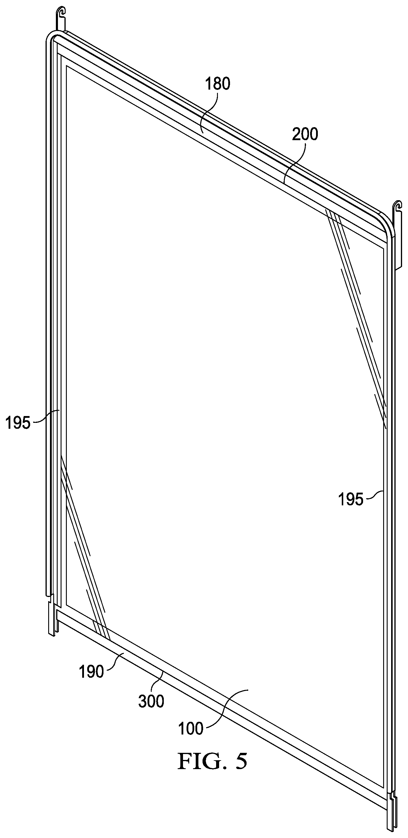
FIG. 5 is a front perspective view of an exemplary backlight assembly where the advertising poster or LCD stack has been removed.
FIG. 6 is a front perspective view of the left top corner of the backlight assembly shown in FIG. 5 where the top bezel has been removed.
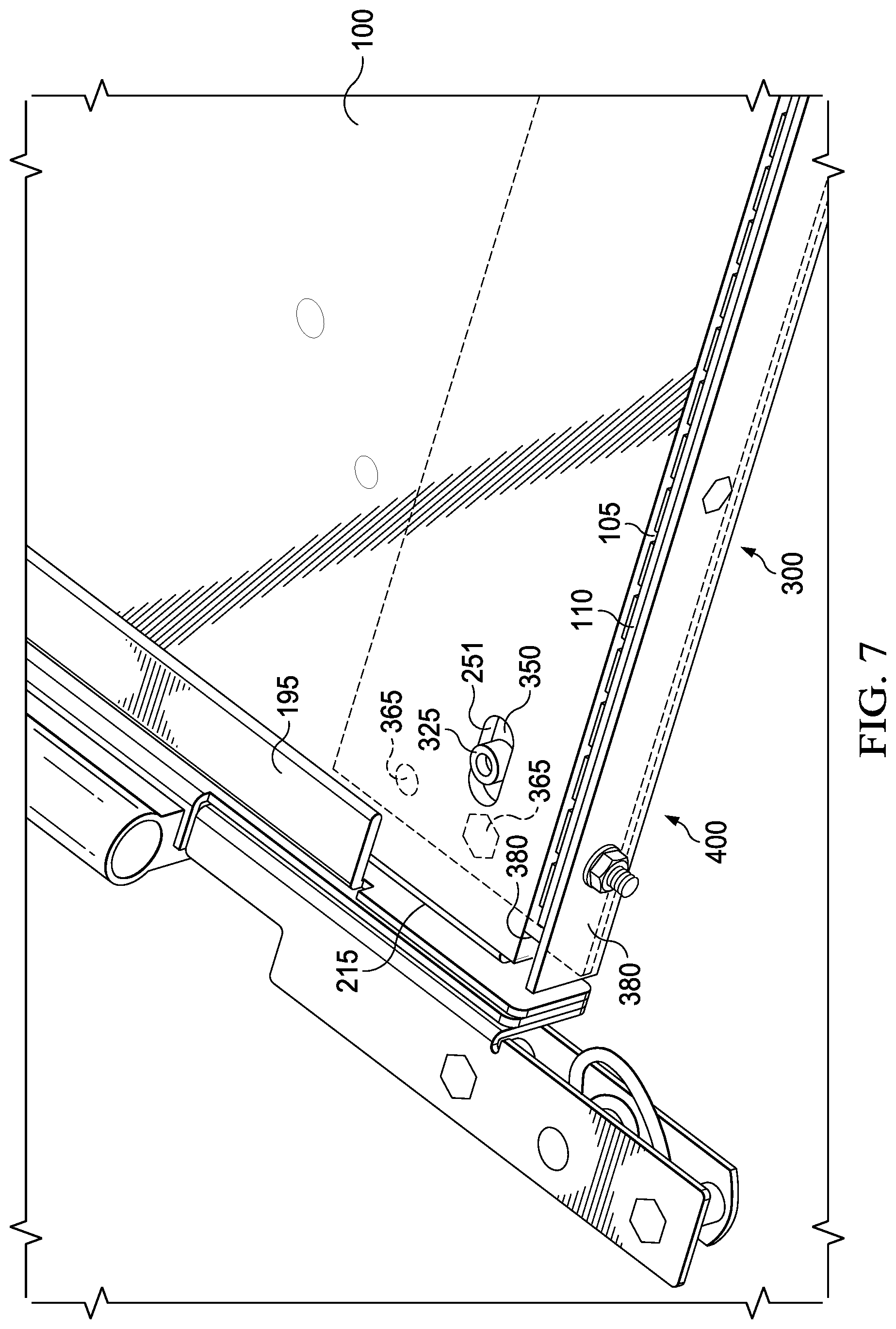
FIG. 7 is a front perspective view of the left bottom corner of the backlight assembly shown in FIG. 5 where the bottom bezel has been removed.
FIG. 8 is the same view as FIG. 7 where the light guide spacer has been removed.
FIG. 9 is a front perspective view of the bottom edge of the backlight assembly shown in FIG. 5 where the bottom bezel and light guide spacer have been removed.
FIG. 10 is a rear perspective view of the left bottom edge of the backlight assembly shown in FIG. 5.
DETAILED DESCRIPTION OF THE EXEMPLARY EMBODIMENTS
The invention is described more fully hereinafter with reference to the accompanying drawings, in which exemplary embodiments of the invention are shown. This invention may, however, be embodied in many different forms and should not be construed as limited to the exemplary embodiments set forth herein. Rather, these embodiments are provided so that this disclosure will be thorough and complete, and will fully convey the scope of the invention to those skilled in the art. In the drawings, the size and relative sizes of layers and regions may be exaggerated for clarity.
The terminology used herein is for the purpose of describing particular embodiments only and is not intended to be limiting of the invention. As used herein, the singular forms "a", "an" and "the" are intended to include the plural forms as well, unless the context clearly indicates otherwise. It will be further understood that the terms "comprises" and/or "comprising," when used in this specification, specify the presence of stated features, integers, steps, operations, elements, and/or components, but do not preclude the presence or addition of one or more other features, integers, steps, operations, elements, components, and/or groups thereof.
Embodiments of the invention are described herein with reference to illustrations that are schematic illustrations of idealized embodiments (and intermediate structures) of the invention. As such, variations from the shapes of the illustrations as a result, for example, of manufacturing techniques and/or tolerances, are to be expected. Thus, embodiments of the invention should not be construed as limited to the particular shapes of regions illustrated herein but are to include deviations in shapes that result, for example, from manufacturing.
Unless otherwise defined, all terms (including technical and scientific terms) used herein have the same meaning as commonly understood by one of ordinary skill in the art to which this invention belongs. It will be further understood that terms, such as those defined in commonly used dictionaries, should be interpreted as having a meaning that is consistent with their meaning in the context of the relevant art and will not be interpreted in an idealized or overly formal sense unless expressly so defined herein.
FIG. 1 is a front perspective view of a backlit display. Here, the backlight and graphic/LCD stack are preferably contained within a housing 10 with a protective transparent sheet 15 placed in front of the graphic/LCD stack. In some embodiments, the protective transparent sheet 15 is glass and may be two sheets of glass laminated together using optical adhesive.
FIG. 2 is an exploded view of an edge-lit backlight assembly. FIG. 3 is a side planar view of the edge-lit backlight assembly shown in FIG. 2 where the advertising poster or LCD stack has been removed.
Here, a lamp and reflector assembly is positioned along the edge of a light guide plate (LGP) such that the light emitted from the lamp and reflector assembly is directed into the LGP. A reflection sheet is preferably placed behind the LGP so that light rays can go through a series of reflections and refractions until exiting the front surface of the LGP and illuminating the advertising poster or LCD stack. Generally, a pair of lamp and reflector assemblies are positioned on opposing edges of the LGP.
As used herein, the term `LCD stack` is defined as any LCD assembly capable of generating an image from backlight illumination. The term `LCD stack` includes any type of LCD design, including but not limited to twisted nematic, in-plane switching, super in-plane switching, TFT dual transistor, fringe field switching and advanced fringe field switching, vertical alignment, advanced super view, and blue phase mode. The various layers and orientation of the layers will vary depending on the particular type of LCD stack and the exemplary embodiments described herein do not require anything specific from the LCD stack other than generating an image.
FIG. 4 is a front planar view of the relative positioning of the LEDs 115 in relation to the light guide 100. The LEDs 115 are preferably mounted to a substrate 110 which is typically some type of printed circuit board (PCB), preferably a metal core PCB. The substrate 110 is preferably positioned so as to produce the desired distance (D) 105 between the edge 101 of the light guide 100 and the LEDs 115. The distance (D) 105 may be selected based on the effectiveness and efficiency of the resulting illumination exiting the front surface of the light guide 100. It is desirable to then maintain this distance (D) 105 even though thermal expansion/contraction of the light guide 100 throughout its lifetime.
FIG. 5 is a front perspective view of an exemplary backlight assembly where the assembly has been removed from the housing 10 and the front protective transparent plate 15 as well as the advertising poster or LCD stack has been removed. The light guide 100 may be surrounded by a top bezel 180 along the top edge 200, bottom bezel 190 along the bottom edge 300, and side bezels 195 along the sides of the backlight assembly. In this embodiment, the LED assemblies are positioned along the top edge 180 and bottom edge 300, but it should be noted that this is not required. In other embodiments the LED assemblies could be positioned along the opposing side vertical edges of the assembly or only along one edge of the assembly, be it top 200, bottom 300, or sides. It should also be noted, that although shown with a `portrait` orientation (where the backlight has a longer vertical dimension than the horizontal dimension) this is not required as the backlight could also be square or could be in the `landscape` orientation (where the backlight has a longer horizontal dimension than the vertical dimension).
FIG. 6 is a front perspective view of the left top corner of the backlight assembly shown in FIG. 5 where the top bezel 180 has been removed. A back pan 215 is preferably fixed within the housing 10 and contains a post 225 which extends forward (towards an intended observer) from the back pan 215 and passes through a slot 250 which is placed within the light guide 100. In this particular embodiment, the distance 105 is provided as the distance between the top edge 101 of the light guide 100 and the LEDs 115. Here, the slot 250 is preferably oriented perpendicular to the distance 105 such that the light guide 100 is fixed within the vertical dimension but is free to move in the horizontal dimension. Some embodiments may use more than one slot 250 in the light guide, with some distributing a plurality of slots across the top edge of the light guide 100.
It should also be noted that some embodiments may utilize clamps rather than the slots shown in the embodiments herein. Thus, a plurality of clamps may be used to hold each LED subassembly at the desired distance from the edge of the light guide, while permitting the light guide itself to move freely within the enclosure. Further, other embodiments may use tabs to hang the light guide vertically while permitting it to expand and contract.
FIG. 7 is a front perspective view of the left bottom corner of the backlight assembly shown in FIG. 5 where the bottom bezel 190 has been removed. Preferably, another slot 251 is placed within the light guide 100, with this slot 251 being placed near the bottom edge of the light guide 100 and is substantially parallel to the slot 250 which is positioned at the top of the light guide 100. A light guide spacer 350 is preferably positioned behind the light guide 100 and contains a post 325 which extends from the light guide spacer 350 forwards (towards an intended observer) and passing through the slot 251. In this way, the light guide 100 can expand/contract in the horizontal dimension without having much effect on the light guide spacer 350. However, when the light guide 100 expands/contracts vertically, through the post 325 it will cause the light guide spacer 350 to move as well.
A connecting assembly 380 is preferably attached to the light guide spacer 350 so that the connecting assembly 380 will move when the light guide spacer 350 moves. The connecting assembly 380 is then preferably connected to another substrate 110 containing a plurality of LEDs 115. In this way, the substrate 110 and LEDs 115 preferably move when the connecting assembly 380 moves. Generally speaking, the light guide spacer 350, connecting assembly 380, substrate 110, and LEDs 115 may be collectively referred to as a sliding LED subassembly, indicated generally as 400. However, it should be noted that other pieces may be included in the sliding LED subassembly 400, and in some embodiments the light guide spacer 350 and connecting assembly 380 may comprise a single piece. In a preferred embodiment, the collective parts of the sliding LED subassembly 400 preferably move together as a unit. As shown and described in this embodiment, the sliding LED subassembly 400 is permitted to move vertically but is constrained from substantially horizontal movement.
A substrate 110 containing a plurality of LEDs 115 is preferably placed adjacent to the bottom edge of the light guide 100 and again is preferably placed to obtain the desired distance 105 from the edge of the light guide 100 to the LEDs 115 on the substrate 110. The slot 251 is again preferably positioned perpendicular to the distance 105. In this embodiment, a pair of posts 365 are used to connect the light guide spacer 350 with the connecting assembly 380, although posts are not required nor is it required that a pair of them are used. Any technique for attaching the light guide spacer 350 to the connecting subassembly 380 would be acceptable (rivets, fasteners, adhesive, welding, etc.) and some embodiments may provide the light guide spacer 350 and connecting assembly 380 as a single unitary piece.
FIG. 8 is the same view as FIG. 7 where the light guide spacer 350 has been removed. The back pan 215 is preferably behind the light guide spacer and may contain a slot 216 to allow the posts 365 (which pass through the slot 216 to connect the light guide spacer 350 with the connecting assembly 380) to slide in a direction perpendicular to the direction of the slot 251 within the light guide 100. Since the substrate 110 containing the LEDs 115 is preferably attached to the connecting assembly 380, the LEDs 115 will move with the connecting assembly 380 which moves with the light guide spacer 350, which moves with the light guide 100 due to the post 325. Therefore, the substrate 110 and LEDs 115 will travel with the light guide 100 as it expands and contracts, thus maintaining the desired distance 105 between the light guide 100 and the LEDs 115.
FIG. 9 is a front perspective view of the bottom edge of the backlight assembly shown in FIG. 5 where the bottom bezel 190 and light guide spacer 350 have been removed. Here, a plurality of slots 216 are distributed across the bottom edge 300 of the backlight assembly, or in this embodiment, across the bottom edge of the back pan 215.
FIG. 10 is a rear perspective view of the left bottom edge of the backlight assembly shown in FIG. 5. The posts 365 are shown connecting the light guide spacer 350 with the connecting assembly 380. As indicated, the sliding LED subassembly 400 (including the substrate 110 and LEDs 115) is permitted to travel back and forth to match the movement of the light guide 100.
Having shown and described a preferred embodiment of the invention, those skilled in the art will realize that many variations and modifications may be made to affect the described invention and still be within the scope of the claimed invention. Additionally, many of the elements indicated above may be altered or replaced by different elements which will provide the same result and fall within the spirit of the claimed invention. It is the intention, therefore, to limit the invention only as indicated by the scope of the claims.
* * * * *
D00000
D00001
D00002
D00003
D00004
D00005
D00006
D00007
D00008
D00009
D00010
XML
uspto.report is an independent third-party trademark research tool that is not affiliated, endorsed, or sponsored by the United States Patent and Trademark Office (USPTO) or any other governmental organization. The information provided by uspto.report is based on publicly available data at the time of writing and is intended for informational purposes only.
While we strive to provide accurate and up-to-date information, we do not guarantee the accuracy, completeness, reliability, or suitability of the information displayed on this site. The use of this site is at your own risk. Any reliance you place on such information is therefore strictly at your own risk.
All official trademark data, including owner information, should be verified by visiting the official USPTO website at www.uspto.gov. This site is not intended to replace professional legal advice and should not be used as a substitute for consulting with a legal professional who is knowledgeable about trademark law.