Fluid exchange devices and related controls, systems, and methods
Procita , et al. February 16, 2
U.S. patent number 10,920,555 [Application Number 16/678,720] was granted by the patent office on 2021-02-16 for fluid exchange devices and related controls, systems, and methods. This patent grant is currently assigned to Flowserve Management Company. The grantee listed for this patent is Flowserve Management Company. Invention is credited to Jason Bandi, Andreas Dreiss, Scott Judge, Tom Knochenhauer, Mark O'Sullivan, Zach Procita, Christopher Shages.


| United States Patent | 10,920,555 |
| Procita , et al. | February 16, 2021 |
Fluid exchange devices and related controls, systems, and methods
Abstract
Pressure exchange devices and related systems may include a valve device configured to selectively place a fluid at a first higher pressure in communication with another fluid at a lower pressure in order to pressurize the another fluid to a second higher pressure. Methods of exchanging pressure between at least two fluid streams may include a pressure exchanger having two low pressure inlets.
| Inventors: | Procita; Zach (Warrington, PA), Bandi; Jason (Irving, TX), O'Sullivan; Mark (Phillipsburg, NJ), Dreiss; Andreas (Hamburg, DE), Judge; Scott (Bethlehem, PA), Shages; Christopher (Bethlehem, PA), Knochenhauer; Tom (Escondido, CA) | ||||||||||
|---|---|---|---|---|---|---|---|---|---|---|---|
| Applicant: |
|
||||||||||
| Assignee: | Flowserve Management Company
(Irving, TX) |
||||||||||
| Family ID: | 70551097 | ||||||||||
| Appl. No.: | 16/678,720 | ||||||||||
| Filed: | November 8, 2019 |
Prior Publication Data
| Document Identifier | Publication Date | |
|---|---|---|
| US 20200149380 A1 | May 14, 2020 | |
Related U.S. Patent Documents
| Application Number | Filing Date | Patent Number | Issue Date | ||
|---|---|---|---|---|---|
| 62758327 | Nov 9, 2018 | ||||
| Current U.S. Class: | 1/1 |
| Current CPC Class: | E21B 43/26 (20130101); F24F 13/00 (20130101); E21B 43/2607 (20200501) |
| Current International Class: | E21B 43/26 (20060101); F24F 13/00 (20060101) |
References Cited [Referenced By]
U.S. Patent Documents
| 1577242 | March 1926 | Andersen |
| 1647189 | November 1927 | Philip et al. |
| 1647734 | November 1927 | Kelly |
| 1769672 | July 1930 | Blair |
| 2365046 | December 1944 | Bottomley |
| 2600836 | June 1952 | Boyd |
| 2615465 | October 1952 | Woodward |
| 3089504 | May 1963 | Crawford |
| 3202108 | August 1965 | Fly |
| 3223173 | December 1965 | Paul, Jr. |
| 3347554 | October 1967 | Jagger et al. |
| 3570510 | March 1971 | Tsutsumi |
| 3583606 | June 1971 | Ewald |
| 3595265 | July 1971 | Cryder et al. |
| 3612361 | October 1971 | Ewald et al. |
| 3661167 | May 1972 | Hussey |
| 3661400 | May 1972 | Weinand |
| 3675825 | July 1972 | Morane |
| 3675935 | July 1972 | Ludwig et al. |
| 3741243 | June 1973 | Deibler et al. |
| 3749291 | July 1973 | Prussin et al. |
| 3756273 | September 1973 | Hengesbach |
| 3776278 | December 1973 | Allen |
| 4024891 | May 1977 | Engel et al. |
| 4123332 | October 1978 | Rotter |
| 4133346 | January 1979 | Smith et al. |
| 4134454 | January 1979 | Taylor |
| 4176063 | November 1979 | Tyler |
| 4234010 | November 1980 | Jenkins et al. |
| 4236547 | December 1980 | Harasewych |
| 4244555 | January 1981 | Maggioni et al. |
| 4308103 | December 1981 | Rotter |
| 4321021 | March 1982 | Pauliukonis |
| 4350176 | September 1982 | Lace |
| 4412632 | November 1983 | Berger et al. |
| 4424917 | January 1984 | Berger et al. |
| 4479356 | October 1984 | Gill |
| 4510963 | April 1985 | Presley et al. |
| 4518006 | May 1985 | Hoffmann et al. |
| 4570853 | February 1986 | Schmied |
| 4579511 | April 1986 | Burns |
| 4586692 | May 1986 | Stephens |
| 4627461 | December 1986 | Gordon |
| 4726530 | February 1988 | Miller et al. |
| 4768542 | September 1988 | Morris |
| 4834193 | May 1989 | Leitko et al. |
| 4999872 | March 1991 | Jentsch |
| 5033557 | July 1991 | Askew |
| 5070817 | December 1991 | Momont |
| 5172918 | December 1992 | Pecht et al. |
| 5232013 | August 1993 | Morris |
| 5234031 | August 1993 | Pickett et al. |
| 5240036 | August 1993 | Morris |
| 5299859 | April 1994 | Tackett et al. |
| 5300041 | April 1994 | Haber et al. |
| 5357995 | October 1994 | King et al. |
| 5797429 | August 1998 | Shumway |
| 5951169 | September 1999 | Oklejas et al. |
| 5992289 | November 1999 | George et al. |
| 6036435 | March 2000 | Oklejas |
| 6126418 | October 2000 | Sinnl |
| 6293245 | September 2001 | Bock |
| RE37921 | December 2002 | Martin et al. |
| 6516897 | February 2003 | Thompson |
| 6540487 | April 2003 | Polizos et al. |
| 6607368 | August 2003 | Ross et al. |
| 6647938 | November 2003 | Gaessler et al. |
| 6659731 | December 2003 | Hauge |
| 7128084 | October 2006 | Long et al. |
| 7201557 | April 2007 | Stover |
| 7306437 | December 2007 | Hauge |
| 7474013 | January 2009 | Greenspan et al. |
| 7670482 | March 2010 | Wietham |
| 7871522 | January 2011 | Stover et al. |
| RE42432 | June 2011 | Stover |
| 7997853 | August 2011 | Pique et al. |
| 8075281 | December 2011 | Martin et al. |
| 8297303 | October 2012 | Desantis et al. |
| 8360250 | January 2013 | Nguyen et al. |
| 8465000 | June 2013 | Bartell et al. |
| 8579603 | November 2013 | Oklejas et al. |
| 8603218 | December 2013 | Montie et al. |
| 8622714 | January 2014 | Andrews |
| 9108162 | August 2015 | Takahashi et al. |
| 9163737 | October 2015 | Andersson |
| 9328743 | May 2016 | Hirosawa et al. |
| 9435354 | September 2016 | Lehner et al. |
| 9440895 | September 2016 | Arluck et al. |
| 9500394 | November 2016 | Manzo |
| 9523261 | December 2016 | Flores et al. |
| 9546671 | January 2017 | Hirosawa et al. |
| 9556736 | January 2017 | Sigurdsson |
| 9587752 | March 2017 | Montague |
| 9604889 | March 2017 | Arluck et al. |
| 9611948 | April 2017 | Andersson |
| 9683574 | June 2017 | Winkler et al. |
| 9695795 | July 2017 | Martin et al. |
| 9739128 | August 2017 | Ghasripoor et al. |
| 9739275 | August 2017 | Robison et al. |
| 9759054 | September 2017 | Gay et al. |
| 9764272 | September 2017 | Martin et al. |
| 9835018 | December 2017 | Krish et al. |
| 9885372 | February 2018 | Arluck et al. |
| 9920774 | March 2018 | Ghasripoor et al. |
| 9945210 | April 2018 | Theodossiou |
| 9945216 | April 2018 | Ghasripoor et al. |
| 9970281 | May 2018 | Ghasripoor et al. |
| 9975789 | May 2018 | Ghasripoor et al. |
| 9976573 | May 2018 | Martin et al. |
| 10001030 | June 2018 | Krish et al. |
| 10006524 | June 2018 | Crump et al. |
| 10024496 | July 2018 | Hauge |
| 10030372 | July 2018 | Di Monte, Sr. |
| 10072675 | September 2018 | McLean et al. |
| 10119379 | November 2018 | Richter et al. |
| 10125796 | November 2018 | Hauge |
| 10138907 | November 2018 | Pinto et al. |
| 10167710 | January 2019 | Ghasripoor et al. |
| 10167712 | January 2019 | Ghasripoor et al. |
| 2002/0025264 | February 2002 | Polizos et al. |
| 2004/0118462 | June 2004 | Baumann |
| 2005/0103386 | May 2005 | Magda |
| 2006/0145426 | July 2006 | Schroeder et al. |
| 2006/0196474 | September 2006 | Magel |
| 2006/0231577 | October 2006 | Powling et al. |
| 2007/0204916 | September 2007 | Clayton et al. |
| 2009/0057084 | March 2009 | Mahawili |
| 2009/0104046 | April 2009 | Martin et al. |
| 2009/0313737 | December 2009 | Richard |
| 2012/0024249 | February 2012 | Fuhrmann et al. |
| 2012/0067825 | March 2012 | Pique et al. |
| 2014/0026608 | January 2014 | Manzo et al. |
| 2014/0048143 | February 2014 | Lehner et al. |
| 2014/0284058 | September 2014 | Watson et al. |
| 2015/0130142 | May 2015 | Zheng et al. |
| 2015/0184540 | July 2015 | Winkler et al. |
| 2015/0292310 | October 2015 | Ghasripoor et al. |
| 2016/0032691 | February 2016 | Richter et al. |
| 2016/0032702 | February 2016 | Gay |
| 2016/0039054 | February 2016 | Ghasripoor et al. |
| 2016/0062370 | March 2016 | Gaines-Germain et al. |
| 2016/0101307 | April 2016 | Montague |
| 2016/0102536 | April 2016 | Knoeller |
| 2016/0138649 | May 2016 | Anderson et al. |
| 2016/0146229 | May 2016 | Martin et al. |
| 2016/0153551 | June 2016 | Schiele et al. |
| 2016/0160849 | June 2016 | Gains-Germain et al. |
| 2016/0160881 | June 2016 | Anderson et al. |
| 2016/0160882 | June 2016 | Morphew |
| 2016/0160887 | June 2016 | Anderson |
| 2016/0160888 | June 2016 | Morphew |
| 2016/0160889 | June 2016 | Hoffman et al. |
| 2016/0160890 | June 2016 | Anderson |
| 2016/0160917 | June 2016 | Deshpande |
| 2016/0377096 | December 2016 | Lehner et al. |
| 2017/0108131 | April 2017 | Andersson |
| 2017/0130743 | May 2017 | Anderson |
| 2017/0191350 | July 2017 | Johns |
| 2017/0254474 | September 2017 | Sauer |
| 2017/0306986 | October 2017 | McLean et al. |
| 2017/0306987 | October 2017 | Theodossiou |
| 2017/0350428 | December 2017 | Martin et al. |
| 2017/0370500 | December 2017 | Haines et al. |
| 2018/0030968 | February 2018 | Verma |
| 2018/0056211 | March 2018 | Seabrook et al. |
| 2018/0087364 | March 2018 | Krish et al. |
| 2018/0094648 | April 2018 | Hoffman et al. |
| 2018/0120197 | May 2018 | Di Monte |
| 2018/0195370 | July 2018 | Theodossiou |
| 2018/0209254 | July 2018 | Ghasripoor |
| 2018/0252239 | September 2018 | Martin et al. |
| 2018/0306672 | October 2018 | Pattom et al. |
| 2018/0347601 | December 2018 | Hoffman et al. |
| 2019/0071340 | March 2019 | Imrie |
| 2020/0149362 | May 2020 | Terwilliger et al. |
| 2020/0149556 | May 2020 | Judge et al. |
| 2020/0149557 | May 2020 | Le Doux, Jr. et al. |
| 2020/0149657 | May 2020 | Christian et al. |
| 2020/0150698 | May 2020 | Judge et al. |
| 101705930 | Feb 2012 | CN | |||
| 102421513 | Apr 2012 | CN | |||
| 206158951 | May 2017 | CN | |||
| 0163897 | Jul 1988 | EP | |||
| 1486706 | Dec 2004 | EP | |||
| 3177429 | Jun 2017 | EP | |||
| 0946494 | Jan 1964 | GB | |||
| 6386657 | Sep 2018 | JP | |||
| 503937 | Jun 2002 | NZ | |||
| 151056 | May 2009 | SG | |||
| 348773 | Aug 1972 | SU | |||
| 02/66816 | Aug 2002 | WO | |||
| 2010/031162 | Nov 2010 | WO | |||
| 2016/022706 | Feb 2016 | WO | |||
| 2016/063194 | Jul 2016 | WO | |||
| 2017/083500 | May 2017 | WO | |||
| 2018/035201 | Feb 2018 | WO | |||
| 2018/085740 | May 2018 | WO | |||
Other References
|
PCT Patent Application No. PCT/US2019/060564, International Search Report dated Feb. 27, 2020, 2 pp. cited by applicant . PCT Patent Application No. PCT/US2019/060564, Written Opinion dated Feb. 27, 2020, 6 pp. cited by applicant . Vorteq Pure Grit, This changes everything, Brochure, Energy Recovery Inc, 8 pages. cited by applicant. |
Primary Examiner: Sayre; James G
Attorney, Agent or Firm: Winchester; Phillips
Parent Case Text
CROSS-REFERENCE TO RELATED APPLICATION
This application claims the benefit of the filing date of U.S. Provisional Patent Application Ser. No. 62/758,327, filed Nov. 9, 2018, for "Fluid Exchange Devices and Related Controls, Systems, and Methods," the disclosure of which is incorporated herein in its entirety by reference.
Claims
What is claimed is:
1. A system for exchanging pressure between at least two fluid streams, the system comprising: a pressure exchange device comprising: at least one tank; at least one high pressure inlet in communication with the at least one tank and for receiving a fluid at a first higher pressure into the at least one tank; at least one low pressure inlet in communication with the at least one tank and for receiving a downhole fluid at a first lower pressure into the at least one tank; at least one high pressure outlet in communication with the at least one tank and for outputting the downhole fluid from the at least one tank at a second higher pressure that is greater than the first lower pressure; at least one low pressure outlet in communication with the at least one tank and for outputting the fluid from the at least one tank at a second lower pressure that is less than the first higher pressure; a valve device comprising a linear valve actuator, wherein the valve actuator is configured to move one or more valve members at variable rates along a stroke of the linear valve actuator in order to selectively fill and empty the at least one tank in communication with the at least one low pressure outlet and the at least one high pressure inlet, the system and the valve device configured to: move the valve actuator at a first higher rate of speed when in communication with a low pressure outlet; move the valve actuator at a second lower rate of speed that is less than the first higher rate of speed when transitioning into communication with the high pressure inlet; selectively place the fluid at the first higher pressure in communication with the downhole fluid at the first lower pressure in order to pressurize the downhole fluid to the second higher pressure; and selectively output the fluid at the second lower pressure from the pressure exchange device through the at least one low pressure outlet; and at least one pump for supplying the fluid at the first higher pressure to the at least one high pressure inlet of the pressure device.
2. The system of claim 1, wherein the at least one low pressure outlet is coupled to the at least one low pressure inlet by a fluid conduit.
3. The system of claim 2, further comprising a blender positioned between the at least one low pressure outlet and the at least one low pressure inlet, the blender configured to modify the fluid at the second lower pressure into the downhole fluid comprising a fracking fluid at the first lower pressure.
4. The system of claim 1, wherein the at least one tank of the pressure exchanger device comprises two tanks coupled to the valve device, and further comprising a piston in each of the two tanks.
5. The system of claim 4, further comprising a control device on each of the tanks, wherein the valve device is configured to alter a position of the one or more valve members in response to the control device detecting a position of the piston in one of the two tanks.
6. The system of claim 4, wherein the at least one high pressure outlet and the at least one low pressure inlet are positioned on a first end of the at least one tank, wherein the valve device is coupled to the at least one tank at a second end of the at least one tank, and wherein the at least one high pressure inlet and the at least one low pressure outlet are positioned on the valve device.
7. The system of claim 1, wherein the at least one tank of the pressure exchanger device comprises two tanks coupled to the valve device.
8. The system of claim 7, wherein the at least one low pressure inlet comprises two low pressure inlets, the at least one low pressure outlet comprises two low pressure outlets, the at least one high pressure outlet comprises two high pressure outlets, and the at least one high pressure inlet comprises only one high pressure inlet.
9. The system of claim 8, wherein the two tanks are in communication with the only one high pressure inlet, and wherein each of the two tanks are in communication with one of the two low pressure inlets, one of the at least two high pressure outlets, and one of the two low pressure outlets.
10. The system of claim 1, wherein the pressure exchanger device comprises at least two pressure exchange devices positioned in a parallel configuration.
11. The system of claim 1, further comprising additional pressure exchange devices, the pressure exchange device and the additional pressure exchange devices being stacked in a parallel configuration with one or more manifolds connecting the pressure exchange device and the additional pressure exchange devices.
12. A system for exchanging pressure between at least two fluid streams, the system comprising: a pressure exchange device comprising: a high pressure inlet for receiving a fluid at a first higher pressure; at least two low pressure inlets for receiving a downhole fluid at a first lower pressure; at least two high pressure outlets for outputting the downhole fluid at a second higher pressure that is greater than the first lower pressure; at least two low pressure outlets for outputting the fluid at a second lower pressure that is less than the first higher pressure; at least two chambers positioned in a parallel configuration, the at least two chambers in fluid communication with the at least two low pressure inlets and the at least two high pressure outlets; a valve device comprising a linear valve actuator, the valve device configured to: selectively place the fluid at the first higher pressure in communication with the downhole fluid at the first lower pressure in the at least two chambers in order to pressurize the downhole fluid to the second higher pressure; and selectively output the fluid at the second lower pressure from the pressure exchange device from the at least two chambers through one of the at least two low pressure outlets; at least one pump for supplying the fluid at the first higher pressure to the high pressure inlet of the pressure device; and additional pressure exchange devices each including at least two additional chambers positioned in a parallel configuration, each of the at least two chambers positioned in the parallel configuration of the pressure exchange device and the at least two additional chambers positioned in the parallel configuration of the additional pressure exchange devices being stacked in a parallel configuration with one or more manifolds connecting the at least two chambers of the pressure exchange device and the at least two additional chambers of the additional pressure exchange devices.
13. The system of claim 12, further comprising additional pressure exchange devices, the pressure exchange device and the additional pressure exchange devices being stacking in a parallel configuration with one or more manifolds connecting the pressure exchange device and the additional pressure exchange devices.
14. A device for exchanging pressure between at least two fluid streams, the device comprising: at least one high pressure inlet for receiving a fluid at a first higher pressure; at least one low pressure inlet for receiving a downhole fluid at a first lower pressure; at least one high pressure outlet for outputting the downhole fluid at a second higher pressure that is greater than the first lower pressure; at least one low pressure outlet for outputting the fluid at a second lower pressure that is less than the first higher pressure; a valve device configured to: selectively place the fluid at the first higher pressure in communication with the downhole fluid at the first lower pressure in order to pressurize the downhole fluid to the second higher pressure; and selectively output the fluid at the second lower pressure from the device through the at least one low pressure outlet; and at least one tank including a piston for separating fluid in the at least one tank, the at least one tank in communication with the at least one high pressure outlet, the at least one low pressure inlet, the at least one high pressure inlet, and the at least one low pressure outlet, wherein the at least one high pressure outlet and the at least one low pressure inlet are positioned on a first end of the at least one tank, wherein the valve device is coupled to the at least one tank at a second end of the at least one tank, and wherein the at least one high pressure inlet and the at least one low pressure outlet are positioned on the valve device; a control device on the at least one tank, wherein the valve device is configured to alter a position of one or more valve members in the valve device in response to the control device detecting a position of the piston in the at least one tank; and wherein the valve device is configured to move at variable rates in order selectively fill and empty at least one tank in communication with the at least one low pressure outlet and the at least one high pressure inlet.
15. The device of claim 14, wherein the valve device is configured to: move at a first higher rate of speed when in communication with the at least one low pressure outlets; and move at a second lower rate of speed that is less than the first higher rate of speed when transitioning between being in communication with the at least one low pressure outlet and being in communication with the at least one high pressure inlet.
16. A method of exchanging pressure between at least two fluid streams, the method comprising: receiving a fluid at a first higher pressure into a pressure exchanger from a high pressure inlet; receiving a downhole fluid at a first lower pressure into the pressure exchanger from a first low pressure inlet; placing the fluid at the first higher pressure in communication with the downhole fluid at the first lower pressure in order to pressurize the downhole fluid to a second higher pressure that is greater than the first lower pressure; outputting the downhole fluid at the second higher pressure; receiving additional fluid at the first higher pressure into the pressure exchanger from the high pressure inlet; receiving additional downhole fluid into the pressure exchanger from a second low pressure inlet; and regulating flow of the additional fluid by moving a valve actuator of a valve device at more than one speed, comprising: moving the valve actuator at a first higher rate of speed when in communication with a low pressure outlet; and moving the valve actuator at a second lower rate of speed that is less than the first higher rate of speed when transitioning into communication with the high pressure inlet.
17. The method of claim 16, further comprising: placing the additional fluid in communication with the additional downhole fluid in order to pressurize the additional downhole fluid to substantially the second higher pressure; and outputting the additional downhole fluid through a high pressure outlet that is separate from another high pressure outlet utilized to output the downhole fluid.
18. The method of claim 16, further comprising monitoring a position of a movable piston for separating fluid in at least one tank of the pressure exchanger.
19. The method of claim 18, further comprising altering a position of one or more valve members in the valve device with the valve actuator in response to a control device detecting a position of the piston in the at least one tank.
20. The method of claim 16, further comprising: after pressuring at least one of the downhole fluid or the additional downhole fluid, outputting a resulting low pressure fluid through at least one of two low pressure fluid outputs; directing the resulting low pressure fluid from both of the two low pressure fluid outputs to a blender; and after directing the resulting low pressure fluid to the blender, directing the resulting low pressure fluid back into the pressure exchanger as another downhole fluid at substantially the first lower pressure.
Description
TECHNICAL FIELD
The present disclosure relates generally to exchange devices. More particularly, embodiments of the present disclosure relate to fluid exchange devices for one or more of exchanging properties (e.g., pressure) between fluids and systems and methods.
BACKGROUND
Industrial processes often involve hydraulic systems including pumps, valves, impellers, etc. Pumps, valves, and impellers may be used to control the flow of the fluids used in the hydraulic processes. For example, some pumps may be used to increase (e.g., boost) the pressure in the hydraulic system, other pumps may be used to move the fluids from one location to another. Some hydraulic systems include valves to control where a fluid flows. Valves may include control valves, ball valves, gate valves, globe valves, check valves, isolation valves, combinations thereof, etc.
Some industrial processes involve the use of caustic fluids, abrasive fluids, and/or acidic fluids. These types of fluids may increase the amount of wear on the components of a hydraulic system. The increased wear may result in increased maintenance and repair costs or require the early replacement of equipment. For example, abrasive, caustic, or acidic fluid may increase the wear on the internal components of a pump such as an impeller, shaft, vanes, nozzles, etc. Some pumps are rebuildable and an operation may choose to rebuild a worn pump replacing the worn parts which may result in extended periods of downtime for the worn pump resulting in either the need for redundant pumps or a drop in productivity. Other operations may replace worn pumps at a larger expense but a reduced amount of downtime.
Well completion operations in the oil and gas industry often involve hydraulic fracturing (often referred to as fracking or fracing) to increase the release of oil and gas in rock formations. Hydraulic fracturing involves pumping a fluid (e.g., frac fluid, fracking fluid, etc.) containing a combination of water, chemicals, and proppant (e.g., sand, ceramics) into a well at high pressures. The high pressures of the fluid increases crack size and crack propagation through the rock formation releasing more oil and gas, while the proppant prevents the cracks from closing once the fluid is depressurized. Fracturing operations use high-pressure pumps to increase the pressure of the fracking fluid. However, the proppant in the fracking fluid increases wear and maintenance on and substantially reduces the operation lifespan of the high-pressure pumps due to its abrasive nature.
BRIEF SUMMARY
Various embodiments may include a system for exchanging pressure between at least two fluid streams. The system may include a pressure exchange device including at least one high pressure inlet, at least one low pressure inlet, at least one high pressure outlet, and at least one low pressure outlet. The at least one high pressure inlet may be configured to receive a fluid at a first higher pressure. The at least one low pressure inlet may be configured to receive a downhole fluid (e.g., fracking fluid, drilling fluid) at a first lower pressure. The at least one high pressure outlet may be configured for outputting the downhole fluid at a second higher pressure that is greater than the first lower pressure. The at least one low pressure outlet may be configured for outputting the fluid at a second lower pressure that is less than the first higher pressure. The pressure exchange device may also include a valve device. The valve device may include a linear valve actuator. The valve device may be configured to selectively place the fluid at the first higher pressure in communication with the downhole fluid at the first lower pressure in order to pressurize the downhole fluid to the second higher pressure; and selectively output the fluid at the second lower pressure from the pressure exchange device through the at least one low pressure outlet. The system may also include at least one pump for supplying the fluid at the first higher pressure to the at least one high pressure inlet of the pressure device.
Another embodiment may include a system for exchanging pressure between at least two fluid streams. The system may include a pressure exchange device including a high pressure inlet, at least two low pressure inlets, at least two high pressure outlets, at least two low pressure outlets, and a valve device. The high pressure inlet may be configured to receive a fluid at a first higher pressure. The at least two low pressure inlets may be configured to receive a downhole fluid (e.g., fracking fluid, drilling fluid) at a first lower pressure. The at least two high pressure outlets may be configured to output the downhole fluid at a second higher pressure that is greater than the first lower pressure. The at least two low pressure outlets may be configure to output the fluid at a second lower pressure that is less than the first higher pressure. The valve device may include a linear valve actuator. The valve device may be configured to selectively place the fluid at the first higher pressure in communication with the downhole fluid at the first lower pressure in order to pressurize the downhole fluid to the second higher pressure, and selectively output the fluid at the second lower pressure from the pressure exchange device through one of the at least two low pressure outlets. The system may also include at least one pump for supplying the fluid at the first higher pressure to the high pressure inlet of the pressure device.
Another embodiment may include a device for exchanging pressure between at least two fluid streams. The device may include at least one high pressure inlet, at least one low pressure inlet, at least one high pressure outlet, and at least one low pressure outlet. The at least one high pressure inlet may be configured for receiving a fluid at a first higher pressure. The at least one low pressure inlet may be configured for receiving a downhole fluid (e.g., fracking fluid, drilling fluid) at a first lower pressure. The at least one high pressure outlet may be configured for outputting the downhole fluid at a second higher pressure that is greater than the first lower pressure. The at least one low pressure outlet may be configured for outputting the fluid at a second lower pressure that is less than the first higher pressure. The device may also include a valve device. The valve device may be configured to selectively place the fluid at the first higher pressure in communication with the downhole fluid at the first lower pressure in order to pressurize the downhole fluid to the second higher pressure. The valve device may also be configured to selectively output the fluid at the second lower pressure from the pressure exchange device through the at least one low pressure outlet. The device may also include at least one tank. The at least one tank may be in communication with the at least on high pressure outlet, the at least one low pressure inlet, the at least one high pressure inlet, and the at least one low pressure inlet. The at least one high pressure outlet and the at least one low pressure inlet may be positioned on a first end of the at least one tank. The at least one high pressure inlet and the at least one low pressure outlet may be positioned on the valve device.
Another embodiment may include a method of exchanging pressure between at least two fluid streams. The method may include receiving a fluid at a first higher pressure into a pressure exchanger from a high pressure inlet and receiving a downhole fluid (e.g., fracking fluid, drilling fluid) at a first lower pressure into the pressure exchanger from a first low pressure inlet. The fluid at the first higher pressure may be placed in communication with the downhole fluid at the first lower pressure in order to pressurize the downhole fluid to a second higher pressure that is greater than the first lower pressure. The downhole fluid may be output at a second higher pressure. The method may also include receiving additional fluid at the first higher pressure into the pressure exchanger from the high pressure inlet, and receiving additional downhole fluid into the pressure exchanger from a second low pressure inlet.
BRIEF DESCRIPTION OF THE DRAWINGS
While the specification concludes with claims particularly pointing out and distinctly claiming what are regarded as embodiments of the present disclosure, various features and advantages of embodiments of the disclosure may be more readily ascertained from the following description of example embodiments of the disclosure when read in conjunction with the accompanying drawings, in which:
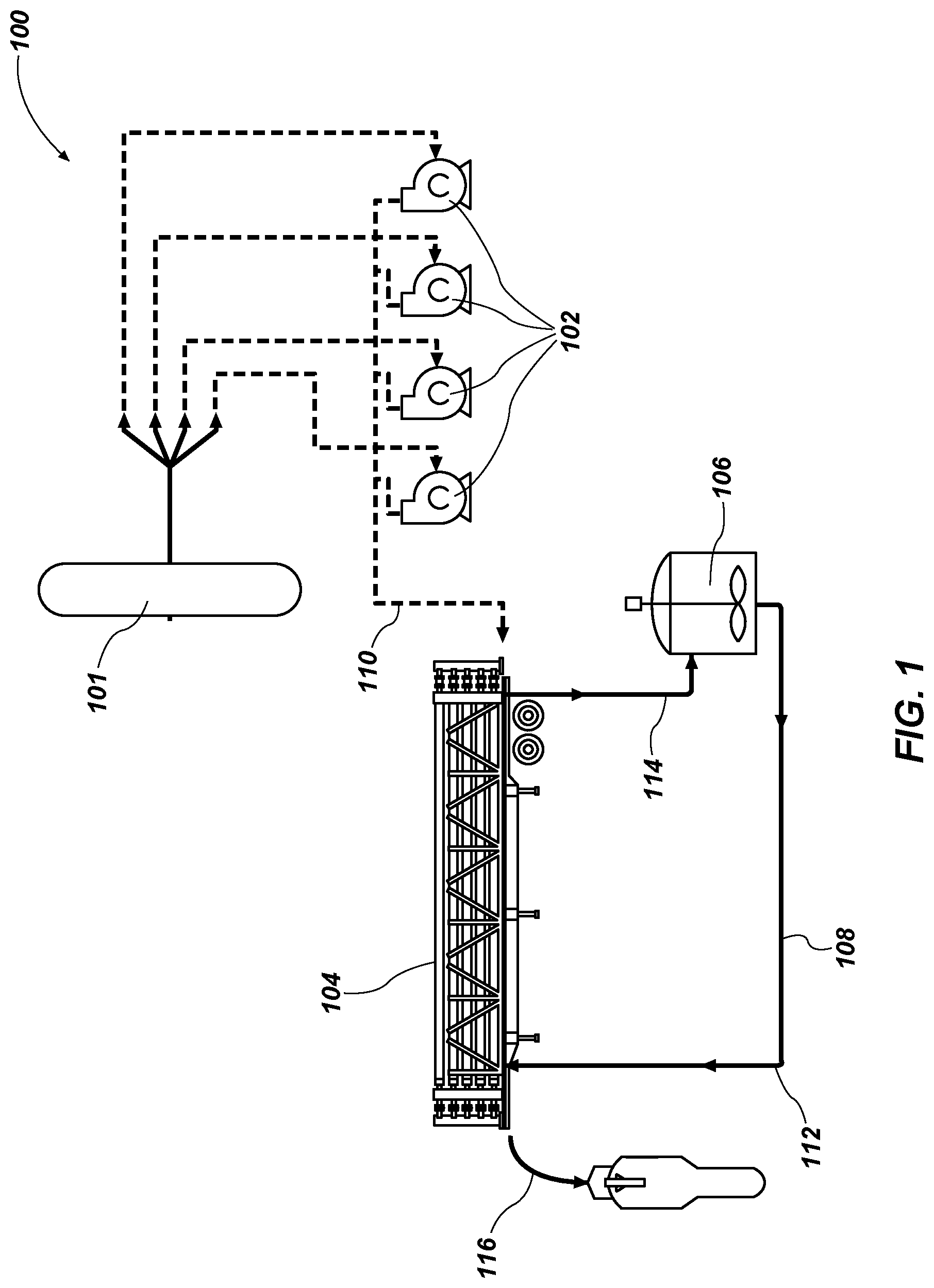
FIG. 1 is schematic view of a hydraulic fracturing system according to an embodiment of the present disclosure;
FIG. 2 is cross-sectional view of a fluid exchanger device according to an embodiment of the present disclosure;
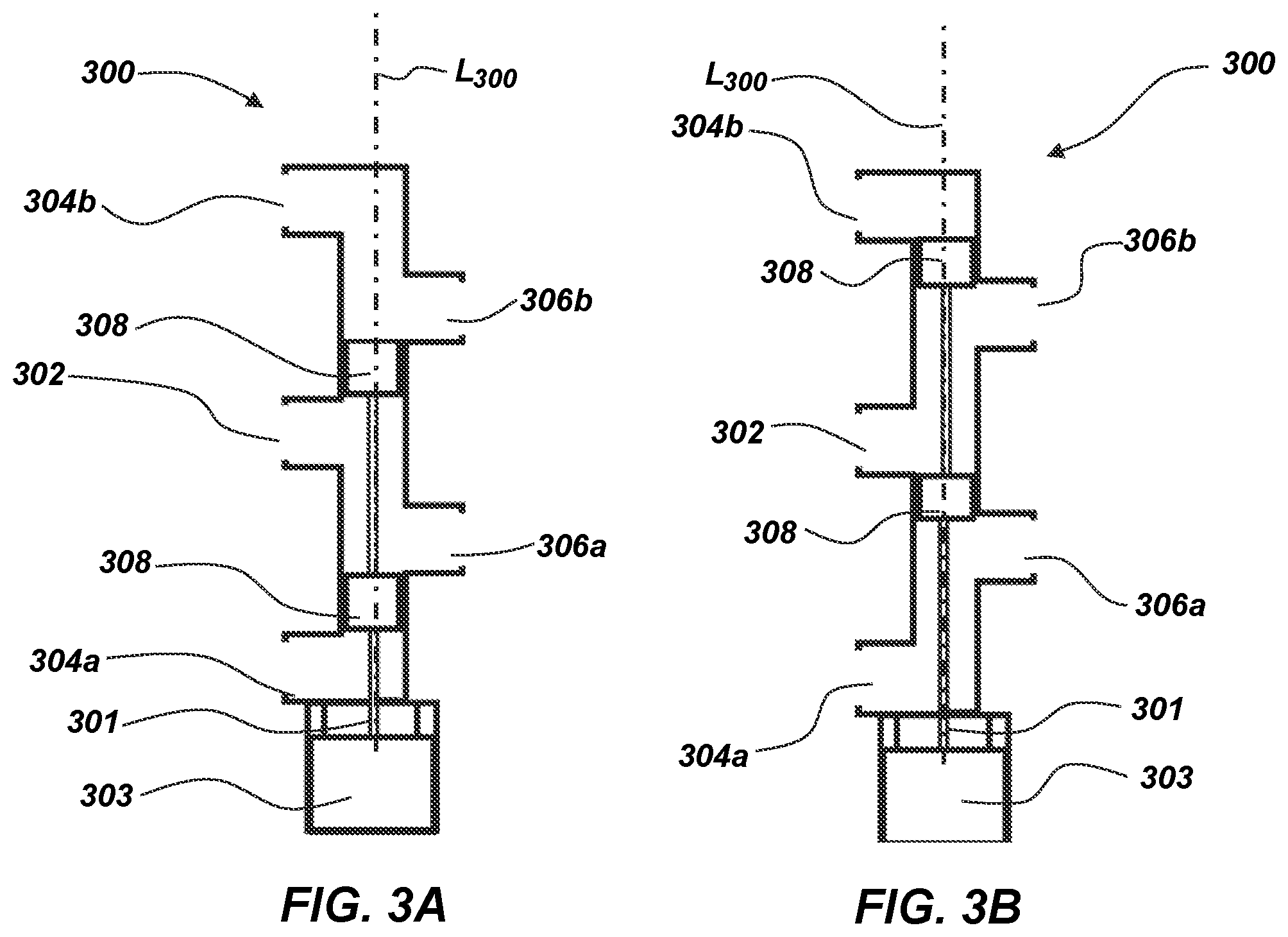
FIG. 3A is a cross-sectional view of a control valve in a first position according to an embodiment of the present disclosure;
FIG. 3B is a cross-sectional view of a control valve in a second position according to an embodiment of the present disclosure; and
FIG. 4 is an isometric view of a modular fluid exchanger device according to an embodiment of the present disclosure.
MODE(S) FOR CARRYING OUT THE INVENTION
The illustrations presented herein are not meant to be actual views of any particular fluid exchanger or component thereof, but are merely idealized representations employed to describe illustrative embodiments. The drawings are not necessarily to scale. Elements common between figures may retain the same numerical designation.
As used herein, relational terms, such as "first," "second," "top," "bottom," etc., are generally used for clarity and convenience in understanding the disclosure and accompanying drawings and do not connote or depend on any specific preference, orientation, or order, except where the context clearly indicates otherwise.
As used herein, the term "and/or" means and includes any and all combinations of one or more of the associated listed items.
As used herein, the terms "vertical" and "lateral" refer to the orientations as depicted in the figures.
As used herein, the term "substantially" or "about" in reference to a given parameter means and includes to a degree that one skilled in the art would understand that the given parameter, property, or condition is met with a small degree of variance, such as within acceptable manufacturing tolerances. For example, a parameter that is substantially met may be at least 90% met, at least 95% met, at least 99% met, or even 100% met.
As used herein, the term "fluid" may mean and include fluids of any type and composition. Fluids may take a liquid form, a gaseous form, or combinations thereof, and, in some instances, may include some solid material. In some embodiments, fluids may convert between a liquid form and a gaseous form during a cooling or heating process as described herein. In some embodiments, the term fluid includes gases, liquids, and/or pumpable mixtures of liquids and solids.
Embodiments of the present disclosure may relate to exchange devices that may be utilized to exchange one or more properties between fluids (e.g., a pressure exchanger). Such exchangers (e.g., pressure exchangers) are sometimes called "flow-work exchangers" or "isobaric devices" and are machines for exchanging pressure energy from a relatively high-pressure flowing fluid system to a relatively low-pressure flowing fluid system.
In some industrial processes, elevated pressures are required in certain parts of the operation to achieve the desired results, following which the pressurized fluid is depressurized. In other processes, some fluids used in the process are available at high-pressures and others at low-pressures, and it is desirable to exchange pressure energy between these two fluids. As a result, in some applications, great improvement in economy can be realized if pressure can be efficiently transferred between two fluids.
In some embodiments, exchangers as disclosed herein may be similar to and include the various components and configurations of the pressure exchangers disclosed in U.S. Pat. No. 5,797,429 to Shumway, issued Aug. 25, 1998, the disclosure of which is hereby incorporated herein in its entirety by this reference.
Although some embodiments of the present disclosure are depicted as being used and employed as a pressure exchanger between two or more fluids, persons of ordinary skill in the art will understand that the embodiments of the present disclosure may be employed in other implementations such as, for example, the exchange of other properties (e.g., temperature, density, etc.) and/or composition between one or more fluids and/or mixing of two or more fluids.
In some embodiments, a pressure exchanger may be used to protect moving components (e.g., pumps, valves, impellers, etc.) in processes were high pressures are needed in a fluid that has the potential to damage the moving components (e.g., abrasive fluid, caustic fluid, acidic fluid, etc.).
For example, pressure exchange devices according to embodiments of the disclosure may be implemented in hydrocarbon related processes, such as, hydraulic fracturing or other drilling operations (e.g., subterranean downhole drilling operations).
As discussed above, well completion operations in the oil and gas industry often involve hydraulic fracturing, drilling operations, or other downhole operations that use high-pressure pumps to increase the pressure of the downhole fluid (e.g., fluid that is intended to be conducted into a subterranean formation or borehole, such as, fracking fluid, drilling fluid, drilling mud). The proppants, chemicals, additives to produce mud, etc. in these fluids often increase wear and maintenance on the high-pressure pumps.
In some embodiments, a hydraulic fracturing system may include a hydraulic energy transfer system that transfers pressure between a first fluid (e.g., a clean fluid, such as a partially (e.g., majority) or substantially proppant free fluid or a pressure exchange fluid) and a second fluid (e.g., fracking fluid, such as a proppant-laden fluid, an abrasive fluid, or a dirty fluid). Such systems may at least partially (e.g., substantially, primarily, entirely) isolate the high-pressure first fluid from the second dirty fluid while still enabling the pressurizing of the second dirty fluid with the high-pressure first fluid and without having to pass the second dirty fluid directly through a pump or other pressurizing device.
While some embodiments discussed herein may be directed to fracking operations, in additional embodiments, the exchanger systems and devices disclosed herein may be utilized in other operations. For example, devices, systems, and/or method disclosed herein may be used in other downhole operations, such as, for example, downhole drilling operations.
FIG. 1 illustrates a system diagram of an embodiment of hydraulic fracturing system 100 utilizing a pressure exchanger between a first fluid stream (e.g., clean fluid stream) and a second fluid stream (e.g., a fracking fluid stream). Although not explicitly described, it should be understood that each component of the system 100 may be directly connected or coupled via a fluid conduit (e.g., pipe) to an adjacent (e.g., upstream or downstream) component. The hydraulic fracturing system 100 may include one or more devices for pressurizing the first fluid stream, such as, for example, frack pumps 102 (e.g., reciprocating pumps, centrifugal pumps, scroll pumps, etc.). The system 100 may include multiple frack pumps 102, such as at least two frack pumps 102, at least four frack pumps 102, at least ten frack pumps 102, at least sixteen frack pumps, or at least twenty frack pumps 102. In some embodiments, the frack pumps 102 may provide relatively and substantially clean fluid at a high pressure to a pressure exchanger 104 from a fluid source 101. In some embodiments, fluid may be provided separately to each pump 102 (e.g., in a parallel configuration). After pressurization in the pumps 102, the high pressure clean fluid 110 may be combined and transmitted to the pressure exchanger 104 (e.g., in a serial configuration).
As used herein, "clean" fluid may describe fluid that is at least partially or substantially free (e.g., substantially entirely or entirely free) of chemicals and/or proppants typically found in a downhole fluid and "dirty" fluid may describe fluid that at least partially contains chemicals and/or proppants typically found in a downhole fluid.
The pressure exchanger 104 may transmit the pressure from the high pressure clean fluid 110 to a low pressure fracking fluid (e.g., fracking fluid 112) in order to provide a high pressure fracking fluid 116. The clean fluid may be expelled from the pressure exchanger 104 as a low pressure fluid 114 after the pressure is transmitted to the low pressure fracking fluid 112. In some embodiments, the low pressure fluid 114 may be an at least partially or substantially clean fluid that substantially lacks chemicals and/or proppants aside from a small amount that may be passed to the low pressure fluid 114 from the fracking fluid 112 in the pressure exchanger 104.
In some embodiments, the pressure exchanger 104 may include one or more pressure exchanger devices (e.g., operating in parallel). In such configurations, the high pressure inputs may be separated and provided to inputs of each of the pressure exchanger devices. The outputs of each of the pressure exchanger devices may be combined as the high pressure fracking fluid exits the pressure exchanger 104. For example, and as discussed below with reference to FIG. 4, the pressure exchanger 104 may include two or more (e.g., three) pressure exchanger devices operating in parallel and oriented in a substantially parallel configuration. As depicted, the pressure exchanger 104 may be provided on a mobile platform (e.g., a truck trailer) that may be relatively easily installed and removed from a fracking well site.
After being expelled from the pressure exchanger 104, the low pressure clean fluid 114 may travel to and be collected in a mixing chamber 106 (e.g., blender unit, mixing unit, etc.). In some embodiments, the low pressure fluid 114 may be converted (e.g., modified, transformed, etc.) to the low pressure fracking fluid 112 in the mixing chamber 106. For example, a proppant may be added to the low pressure clean fluid 114 in the mixing chamber 106 creating a low pressure fracking fluid 112. In some embodiments, the low pressure clean fluid 114 may be expelled as waste.
In many hydraulic fracturing operations, a separate process may be used to heat the fracking fluid 112 before the fracking fluid 112 is discharged downhole (e.g., to ensure proper blending of the proppants in the fracking fluid). In some embodiments, using the low pressure clean fluid 114 to produce the fracking fluid 112 may eliminate the step of heating the fracking fluid. For example, the low pressure clean fluid 114 may be at an already elevated temperature as a result of the fracking pumps 102 pressurizing the high pressure clean fluid 110. After transferring the pressure in the high pressure clean fluid 112 that has been heated by the pumps 102, the now low pressure clean fluid 114 retains at least some of that heat energy as it is passed out of the pressure exchanger 104 to the mixing chamber 106. In some embodiments, using the low pressure clean fluid 114 at an already elevated temperature to produce the fracking fluid may result in the elimination of the heating step for the fracking fluid. In other embodiments, the elevated temperature of the low pressure clean fluid 114 may result in a reduction of the amount of heating required for the fracking fluid.
After the proppant is added to the low pressure now fracking fluid 114, the low pressure fracking fluid 112 may be expelled from the mixing chamber 106. The low pressure fracking fluid 112 may then enter the pressure exchanger 104 on the fracking fluid end through a fluid conduit 108 connected (e.g., coupled) between the mixing chamber 106 and the pressure exchanger 104. Once in the pressure exchanger 104, the low pressure fracking fluid 112 may be pressurized by the transmission of pressure from the high pressure clean fluid 110 through the pressure exchanger 104. The high pressure fracking fluid 116 may then exit the pressure exchanger 104 and be transmitted downhole.
Hydraulic fracturing systems generally require high operating pressures for the high pressure fracking fluid 116. In some embodiments, the desired pressure for the high pressure fracking fluid 116 may be between about 8,000 PSI (55,158 kPa) and about 12,000 PSI (82,737 kPa), such as between about 9,000 PSI (62,052 kPa) and about 11,000 PSI (75,842 kPa), or about 10,000 PSI (68,947 kPa).
In some embodiments, the high pressure clean fluid 110 may be pressurized to a pressure at least substantially the same or slightly greater than the desired pressure for the high pressure fracking fluid 116. For example, the high pressure clean fluid 110 may be pressurized to between about 0 PSI (0 kPa) and about 1000 PSI (6,894 kPa) greater than the desired pressure for the high pressure fracking fluid 116, such as between about 200 PSI (1,379 kPa) and about 700 PSI (4,826 kPa) greater than the desired pressure, or between about 400 PSI (2,758 kPa) and about 600 PSI (4,137 kPa) greater than the desired pressure, to account for any pressure loss during the pressure and exchange process.
FIG. 2 illustrates an embodiment of a pressure exchanger 200. The pressure exchanger 200 may be a linear pressure exchanger in the sense that it is operated by moving or translating an actuation assembly substantially along a linear path. For example, the actuation assembly may be moved linearly to selectively place the low and high pressure fluids in at least partial communication (e.g., indirect communication where the pressure of the high pressure fluid may be transferred to the low pressure fluid) as discussed below in greater detail.
The linear pressure exchanger 200 may include one or more (e.g., two) chambers 202a, 202b (e.g., tanks, collectors, cylinders, tubes, pipes, etc.). The chambers 202a, 202b (e.g., parallel chambers 202a, 202b) may include pistons 204a, 204b configured to substantially maintain the high pressure clean fluid 210 and low pressure clean fluid 214 (e.g., the clean side) separate from the high pressure dirty fluid 216 and the low pressure dirty fluid 212 (e.g., the dirty side) while enabling transfer of pressure between the respective fluids 210, 212, 214, and 216. The pistons 204a, 204b may be sized (e.g., the outer diameter of the pistons 204a, 204b relative to the inner diameter of the chambers 202a, 204b) to enable the pistons 204a, 204b to travel through the chamber 202a, 202b while minimizing fluid flow around the pistons 204a, 204b.
The linear pressure exchanger 200 may include a clean control valve 206 configured to control the flow of high pressure clean fluid 210 and low pressure clean fluid 214. Each of the chambers 202a, 202b may include one or more dirty control valves 207a, 207b, 208a, and 208b configured to control the flow of the low pressure dirty fluid 212 and the high pressure dirty fluid 216.
While the embodiment of FIG. 2 contemplates a linear pressure exchanger 200, other embodiments, may include other types of pressure exchangers that involve other mechanisms for selectively placing the low and high pressure fluids in at least partial communication (e.g., a rotary actuator such as those disclosed in U.S. Pat. No. 9,435,354, issued Sep. 6, 2016, the disclosure of which is hereby incorporated herein in its entirety by this reference, etc.).
In some embodiments, the clean control valve 206, which includes an actuation stem 203 that moves one or more stoppers 308 along (e.g., linearly along) a body 205 of the valve 206, may selectively allow (e.g., input, place, etc.) high pressure clean fluid 210 provided from a high pressure inlet port 302 to enter a first chamber 202a on a clean side 220a of the piston 204a. The high pressure clean fluid 210 may act on the piston 204a moving the piston 204a in a direction toward the dirty side 221a of the piston 204a and compressing the dirty fluid in the first chamber 202a to produce the high pressure dirty fluid 216. The high pressure dirty fluid 216 may exit the first chamber 202a through the dirty discharge control valve 208a (e.g., outlet valve, high pressure outlet). At substantially the same time, the low pressure dirty fluid 212 may be entering the second chamber 202b through the dirty fill control valve 207b (e.g., inlet valve, low pressure inlet). The low pressure dirty fluid 212 may act on the dirty side 221b of the piston 204b moving the piston 204b in a direction toward the clean side 220b of the piston 204b in the second chamber 202b. The low pressure clean fluid 214 may be discharged (e.g., emptied, expelled, etc.) through the clean control valve 206 as the piston 204b moves in a direction toward the clean side 220b of the piston 204b reducing the space on the clean side 220b of the piston 204b within the second chamber 202b. A cycle of the pressure exchanger is completed once each piston 204a, 204b moves the substantial length (e.g., the majority of the length) of the respective chamber 202a, 202b (which "cycle" may be a half cycle with the piston 204a, 204b moving in one direction along the length of the chamber 202a, 202b and a full cycle includes the piston 204a, 204b moving in the one direction along the length of the chamber 202a, 202b and then moving in the other direction to return to substantially the original position). In some embodiments, only a portion of the length may be utilized (e.g., in reduced capacity situations). Upon the completion of a cycle, the actuation stem 203 of the clean control valve 206 may change positions enabling the high pressure clean fluid 210 to enter the second chamber 202b, thereby changing the second chamber 202b to a high pressure chamber and changing the first chamber 202a to a low pressure chamber and repeating the process.
In some embodiments, each chamber 202a, 202b may have a higher pressure on one side of the pistons 204a, 204b to move the piston in a direction away from the higher pressure. For example, the high pressure chamber may experience pressures between about 8,000 PSI (55,158 kPa) and about 13,000 PSI (89,632 kPa) with the highest pressures being in the high pressure clean fluid 210 to move the piston 204a, 204b away from the high pressure clean fluid 210 compressing and discharging the dirty fluid to produce the high pressure dirty fluid 216. The low pressure chamber 202a, 202b may experience much lower pressures, relatively, with the relatively higher pressures in the currently low pressure chamber 202a, 202b still being adequate enough in the low pressure dirty fluid 212 to move the piston 204a, 204b in a direction away from the low pressure dirty fluid 212 discharging the low pressure clean fluid 214. In some embodiments, the pressure of the low pressure dirty fluid 212 may be between about 100 PSI (689 kPa) and about 700 PSI (4,826 kPa), such as between about 200 PSI (1,379 kPa) and about 500 PSI (3,447 kPa), or between about 300 PSI (2,068 kPa) and about 400 PSI (2758 kPa).
Referring back to FIG. 1, in some embodiments, the system 100 may include one or more optional devices (e.g., a pump) to pressurize the low pressure dirty fluid 212 (e.g., to a pressure level that is suitable to move the piston 204a, 204b toward the clean side) as it is being provided into the chambers 202a, 202b.
Referring again to FIG. 2, if any fluid pushes past the piston 204a, 204b (e.g., leak by, blow by, etc.) it will generally tend to flow from the higher pressure fluid to the lower pressure fluid. The high pressure clean fluid 210 may be maintained at the highest pressure in the system such that the high pressure clean fluid 210 may not generally become substantially contaminated. The low pressure clean fluid 214 may be maintained at the lowest pressure in the system. Therefore, it is possible that the low pressure clean fluid 214 may become contaminated by the low pressure dirty fluid 212. In some embodiments, the low pressure clean fluid 214 may be used to produce the low pressure dirty fluid 212 substantially nullifying any detriment resulting from the contamination. Likewise, any contamination of the high pressure dirty fluid 216 by the high pressure clean fluid 210 would have minimal effect on the high pressure dirty fluid 216.
In some embodiments, the dirty control valves 207a, 207b, 208a, 208b may be check valves (e.g., clack valves, non-return valves, reflux valves, retention valves, or one-way valves). For example, one or more of the dirty control valves 207a, 207b, 208a, 208b may be a ball check valve, diaphragm check valve, swing check valve, tilting disc check valve, clapper valve, stop-check valve, lift-check valve, in-line check valve, duckbill valve, etc. In additional embodiments, one or more of the dirty control valves 207a, 207b, 208a, and 208b may be actuated valves (e.g., solenoid valves, pneumatic valves, hydraulic valves, electronic valves, etc.) configured to receive a signal from a controller and open or close responsive the signal.
The dirty control valves 207a, 207b, 208a, 208b may be arranged in opposing configurations such that when the chamber 202a, 202b is in the high pressure configuration the high pressure dirty fluid opens the dirty discharge control valve 208a, 208b while the pressure in the chamber 202a, 202b holds the dirty fill control valve 207a, 207b closed. For example, the dirty discharge control valve 208a, 208b comprises a check valve that opens in a first direction out of the chamber 202a, 202b, while the dirty fill control valve 207a, 207b comprises a check valve that opens in a second, opposing direction into the chamber 202a, 202b.
The dirty discharge control valves 208a, 208b may be connected to a downstream element (e.g., a fluid conduit, a separate or common manifold) such that the high pressure in the downstream element holds the dirty discharge valve 208a, 208b closed in the chamber 202a, 202b that is in the low pressure configuration. Such a configuration enables the low pressure dirty fluid to open the dirty fill control valve 207a, 207b and enter the chamber 202a, 202b.
FIGS. 3A and 3B illustrate a cross sectional view of an embodiment of a clean control valve 300 at two different positions. In some embodiments, the clean control valve 300 may be similar to the control valve 206 discussed above. The clean control valve 300 may be a multiport valve (e.g., 4 way valve, 5 way valve, LinX.RTM. valve, etc.). The clean control valve 300 may have one or more high pressure inlet ports (e.g., one port 302), one or more low pressure outlet ports (e.g., two ports 304a, 304b), and one or more chamber connection ports (e.g., two ports 306a, 306b). The clean control valve 300 may include at least two stoppers 308 (e.g., plugs, pistons, discs, valve members, etc.). In some embodiments, the clean control valve 300 may be a linearly actuated valve. For example, the stoppers 308 may be linearly actuated such that the stoppers 308 move along a substantially straight line (e.g., along a longitudinal axis L.sub.300 of the clean control valve 300).
The clean control valve 300 may include an actuator 303 configured to actuate the clean control valve 300 (e.g., an actuator coupled to a valve stem 301 of the clean control valve 300). In some embodiments, the actuator 303 may be electronic (e.g., solenoid, rack and pinion, ball screw, segmented spindle, moving coil, etc.), pneumatic (e.g., tie rod cylinders, diaphragm actuators, etc.), or hydraulic. In some embodiments, the actuator 303 may enable the clean control valve 300 to move the valve stem 301 and stoppers 308 at variable rates (e.g., changing speeds, adjustable speeds, etc.).
FIG. 3A illustrates the clean control valve 300 in a first position. In the first position, the stoppers 308 may be positioned such that the high pressure clean fluid may enter the clean control valve 300 through the high pressure inlet port 302 and exit into a first chamber through the chamber connection port 306a. In the first position, the low pressure clean fluid may travel through the clean control valve 300 between the chamber connection port 306b and the low pressure outlet port 304b (e.g., may exit through the low pressure outlet port 304b).
FIG. 3B illustrates the clean control valve 300 in a second position. In the second position, the stoppers 308 may be positioned such that the high pressure clean fluid may enter the clean control valve 300 through the high pressure inlet port 302 and exit into a second chamber through the chamber connection port 306b. The low pressure clean fluid may travel through the clean control valve 300 between the chamber connection port 306a and the low pressure outlet port 304a (e.g., may exit through the low pressure outlet port 304a).
Now referring to FIGS. 2, 3A, and 3B, the clean control valve 206 is illustrated in the first position with the high pressure inlet port 302 connected to the chamber connection port 306a providing high pressure clean fluid to the first chamber 202a. Upon completion of the cycle, the clean control valve 206 may move the stoppers 308 to the second position thereby connecting the high pressure inlet port 302 to the second chamber 202b through the chamber connection port 306b.
In some embodiments, the clean control valve 206 may pass through a substantially fully closed position in the middle portion of a stroke between the first position and the second position. For example, in the first position, the stoppers 308 may maintain a fluid pathway between the high pressure inlet port 302 and the chamber connection port 306a and a fluid pathway between the chamber connection port 306b and the low pressure outlet port 304b. In the second position, the stoppers 308 may maintain a fluid pathway between the high pressure inlet port 302 and the chamber connection port 306b and a fluid pathway between the chamber connection port 306a and the low pressure outlet port 304a. Transitioning between the first and second positions may involve at least substantially closing both fluid pathways to change the connection of the chamber connection port 306a from the high pressure inlet port 302 to the low pressure outlet port 304a and to change the connection of the chamber connection port 306b from the low pressure outlet port 306b to the high pressure inlet port 302. The fluid pathways may at least substantially close at a middle portion of the stroke to enable the change of connections. Opening and closing valves, where fluids are operating at high pressures, may result in pressure pulsations (e.g., water hammer) that can result in damage to components in the system when high pressure is suddenly introduced or removed from the system. As a result, pressure pulsations may occur in the middle portion of the stroke when the fluid pathways are closing and opening respectively.
In some embodiments, the actuator 303 may be configured to move the stoppers 308 at variable speeds along the stroke of the clean control valve 206. As the stoppers 308 move from the first position to the second position, the stoppers 308 may move at a high rate of speed while traversing a first portion of the stroke that does not involve newly introducing flow from the high pressure inlet port 302 into the chamber connection ports 306a, 306b. The stoppers 308 may decelerate to a low rate of speed as the stoppers 308 approach a closed position (e.g., when the stoppers 308 block the chamber connection ports 306a, 306b during the transition between the high pressure inlet port 302 connection and the low pressure outlet port 304a, 304b connection) at a middle portion of the stroke. The stoppers 308 may continue at a lower rate of speed, as the high pressure inlet port 302 is placed into communication with one of the chamber connection ports 306a, 306b. After traversing the chamber connection ports 306a, 306b, the stoppers 308 may accelerate to another high rate of speed as the stoppers 308 approach the second position. The low rate of speed in the middle portion of the stroke may reduce the speed that the clean control valve 206 opens and closes enabling the clean control valve to gradually introduce and/or remove the high pressure from the chambers 202a, 202b.
In some embodiments, the motion of the pistons 204a, 204b may be controlled by regulating the rate of fluid flow (e.g., of the incoming fluid) and/or a pressure differential between the clean side 220a, 220b of the pistons 204a, 204b, and the dirty side 221a, 221b of the pistons 204a, 204b at least partially with the movement of the clean control valve 206. In some embodiments, it may be desirable for the piston 204a, 204b in the low pressure chamber 202a, 202b to move at substantially the same speed as the piston 204a, 204b in the high pressure chamber 202a, 202b either by manipulating their pressure differentials in each chamber and/or by controlling the flow rates of the fluid in and out of the chambers 202a, 202b. However, the piston 204a, 204b in the low pressure chamber 202a, 202b may tend to move at a greater speed than the piston 204a, 204b in the high pressure chamber 202a, 202b.
In some embodiments, the rate of fluid flow and/or the pressure differential may be varied to control acceleration and deceleration of the pistons 204a, 204b (e.g., by manipulating and/or varying the stroke of the clean control valve 206 and/or by manipulating the pressure in the fluid streams with one or more pumps). For example, increasing the flow rate and/or the pressure of the high pressure clean fluid 210 when the piston 204a, 204b is near a clean end 224 of the chamber 202a, 202b at the beginning of the high pressure stroke may increase the rate of fluid flow and/or the pressure differential in the chamber 202a, 202b. Increasing the rate of fluid flow and/or the pressure differential may cause the piston 204a, 204b to accelerate to or move at a faster rate. In another example, the flow rate and/or the pressure of the high pressure clean fluid 210 may be decreased when the piston 204a, 204b approaches a dirty end 226 of the chamber 202a, 202b at the end of the high pressure stroke. Decreasing the rate of fluid flow and/or the pressure differential may cause the piston 204a, 204b to decelerate and/or stop before reaching the dirty end of the respective chamber 202a, 202b.
Similar control with the stroke of the clean control valve 206 may be utilized to prevent the piston 204a, 204b from traveling to the furthest extent of the clean end of the chambers 202a, 202b. For example, the clean control valve 206 may close off one of the chamber connection ports 306a, 306b before the piston 204a, 204b contacts the furthest extent of the clean end of the chambers 202a, 202b by preventing any further fluid flow and slowing and/or stopping the piston 204a, 204b. In some embodiments, the clean control valve 206 may open one the chamber connection ports 306a, 306b into communication with the high pressure inlet port 302 before the piston 204a, 204b contacts the furthest extent of the clean end of the chambers 202a, 202b in order to slow, stop, and/or reverse the motion of the piston 204a, 204b.
If the pistons 204a, 204b reach the clean end 224 or dirty end 226 of the respective chambers 202a, 202b the higher pressure fluid may bypass the piston 204a, 204b and mix with the lower pressure fluid. In some embodiments, mixing the fluids may be desirable. For example, if the pistons 204a, 204b reach the dirty end 226 of the respective chambers 202a, 202b during the high pressure stroke, the high pressure clean fluid 210 may bypass the piston 204a, 204b (e.g., by traveling around the piston 204a, 204b or through a valve in the piston 204a, 204b) flushing any residual contaminants from the surfaces of the piston 204a, 204b. In some embodiments, mixing the fluids may be undesirable. For example, if the pistons 204a, 204b reach the clean end 224 of the respective chambers 202a, 202b during the low pressure stroke, the low pressure dirty fluid 212 may bypass the piston 204a, 204b and mix with the low pressure clean fluid contaminating the clean area in the clean control valve 206 with the dirty fluid.
In some embodiments, the system 100 may prevent the pistons 204a, 204b from reaching the clean end 224 of the respective chambers 202a, 202b. For example, the clean control valve 206 may include a control device 207 (e.g., sensor, safety, switch, etc.) to trigger the change in position of the clean control valve 206 on detecting the approach of the piston 204a, 204b to the clean end 224 of the respective chamber 202a, 202b such that the system 100 may utilize the clean control valve 206 to change flow path positions before the piston 204a, 204b reaches the clean end 224 of the chamber 202a, 202b.
In some embodiments, pressure spikes may occur in the fluids. For example, pressure spikes may occur in the high pressure clean fluid 210 when the clean control valve 206 closes or opens. In some embodiments, the chambers 202a, 202b and pistons 204a, 204b may dampen (e.g., reduce, balance, etc.) any pressure spikes in the high pressure clean fluid 210 when transferring pressure from the high pressure clean fluid 210 to the dirty fluid 212 producing the high pressure dirty fluid 216 while minimizing pressure spikes.
In some embodiments, duration of each cycle may correlate to the production of the system 100. For example, in each cycle the pressure exchanger 200 may move a specific amount of dirty fluid defined by the combined capacity of the chambers 202a, 202b. In some embodiments, the pressure exchanger 200 may move between about 40 gallons (75.7 liters) and about 90 gallons (340.7 liters), such as between about 60 gallons (227.1 liters) and about 80 gallons (302.8 liters), or between about 65 gallons (246.1 liters) and about 75 gallons (283.9 liters). For example, in a system with one or more tanks (e.g., two tanks), each tank in the pressure exchanger 200 may move between about 40 gallons (75.7 liters) and about 90 gallons (340.7 liters) (e.g., two about 60 gallon (227.1 liters) tanks that move about 120 gallons (454.2 liters) per cycle).
In some embodiments, the duration of the cycles may be controlled by varying the rate of fluid flow and/or the pressure differential across the pistons 204a, 204b with the clean control valve 206. For example, the flow rate and/or pressure of the high pressure clean fluid 210 may be controlled such that the cycles correspond to a desired flow rate of the dirty fluid 112. In some embodiments, the flow rate and/or the pressure may be controlled by controlling a speed of the frac pumps 102 (FIG. 1) (e.g., through a variable frequency drive (VFD), throttle control, etc.), through a mechanical pressure control (e.g., variable vanes, pressure relief system, bleed valve, etc.), or by changing the position of the clean control valve 206 to restrict flow into or out of the chambers 202a, 202b.
In some embodiments, maximum production may be the desired condition which may use the shortest possible duration of the cycle. In some embodiments, the shortest duration of the cycle may be defined by the speed of the actuator 303 on the clean control valve 206, 300. In some embodiments, the shortest duration of the cycle may be defined by the maximum pressure of the high pressure clean fluid 210. In some embodiments, the shortest duration may be defined by the response time of the clean control valve 206, 300.
Now referring to FIGS. 1 and 2, in some embodiments, the pressure exchanger 104 may be formed from multiple linear pressure exchangers 200 operating in parallel. For example the pressure exchanger 104 may be formed from two or more pressure exchangers (e.g., three, four, five, or more pressure exchangers stacked in a parallel configuration. In some embodiments, the pressure exchanger 104 may be modular such that the number of linear pressure exchangers 200 may be changed by adding or removing sections of linear pressure exchangers based on flow requirements. In some embodiments, an operation may include multiple systems operating in an area and the pressure exchangers 104 for each respective system may be adjusted as needed by adding or removing linear pressure exchangers from other systems in the same area.
FIG. 4 illustrates an embodiment of a pressure exchanger 400, which may be module as the number of the individual pressure exchanger devices 401. In some embodiments, the pressure exchanger 400 may be constructed into or on a mobile platform, such as, for example, a tractor trailer (e.g., semi-trailer, flat-bed trailer, etc.). In some embodiments, the pressure exchanger 400 may include multiple high pressure inlets 402 (e.g., couplings, connections, etc.) configured to connect to a high pressure supply such as high pressure pumps (e.g., frac pumps 102 (FIG. 1)). The high pressure inlets 402 may be connected to a high pressure clean manifold 404. The high pressure clean manifold 404 may be connected to the high pressure inlet port 406 of the clean control valve 408. In some embodiments, the high pressure clean manifold 404 may connect to more than one clean control valves 408 such as at two clean control valves 408, three clean control valves 408, five clean control valves 408, or eight clean control valves. The clean control valve(s) 408 may be connected to chambers 410 in a similar manner to that describe in FIG. 2 above. In some embodiments, the number of chambers 410 may correlate to the number of clean control valves 408. For example, each clean control valve 408 may be associated with two chambers 410. For example, embodiments with three clean control valves 408 may include six chambers 410, embodiments with four clean control valves 408 may include eight chambers 410, embodiments with six clean control valves 408 may include twelve chambers 410, etc.
In some embodiments, the low pressure outlet ports 412a and 412b of the clean control valve 408 may be connected to a low pressure clean manifold. The low pressure clean manifold may include a coupling (e.g., connection, fitting, etc.) configured to connect the low pressure clean manifold to an external device. In some embodiments, the pressure exchanger 400 may include more than one low pressure clean manifolds 414a, 414b. For example, a first low pressure clean manifold 414a may be connected to a first low pressure outlet port 412a of the clean control valve 408 and a second low pressure clean manifold 414b may be connected to a second low pressure outlet port 412b of the clean control valve 408. In some embodiments, the external device may be a mixing chamber configured to mix the low pressure clean fluid with a material to produce the dirty fluid (e.g., fracking fluid) for further processing. In some embodiments, the external device may be a waste tank or a drain line configured to expel the used clean fluid as waste.
In some embodiments, the pressure exchanger 400 may include low pressure inlets 416. The low pressure inlets 416 may be configured to receive a low pressure dirty fluid. In some embodiments, the low pressure inlets 416 may be connected to a low pressure dirty manifold 418. In some embodiments, the low pressure inlets 416 may be connected to at least two low pressure dirty manifolds 419a, 419b. For example, half of the low pressure inlets 416 may be connected to a first low pressure dirty manifold 419a on a first side 420a of the pressure exchanger 400 and the other half of the low pressure inlets 416 may be connected to a second low pressure dirty manifold 419b on a second side 420b of the pressure exchanger 400. In some embodiments, the at least two low pressure dirty manifolds 419a, 419b may be connected to a common low pressure dirty manifold 418 through a fluid conduit 422 (e.g., pipe, manifold, tube, etc.). The low pressure inlets 416 may be connected to the at least two low pressure dirty manifolds 419a, 419b through the common low pressure dirty manifold 418.
In some embodiments, the at least two low pressure dirty manifolds 419a, 419b may be connected to the low pressure inlet ports 424 of the pressure exchanger 400. In some embodiments, the low pressure inlet ports 424 may be valves (e.g., check valves, control valves, etc.). The low pressure inlet ports 424 may be configured to enable the low pressure dirty fluid to enter the chambers 410.
In some embodiments, the chambers 410 may also include high pressure outlet ports 426 (e.g., control valves, check valves, etc.). In some embodiments, the high pressure outlet ports 426 may be configured to release the high pressure dirty fluid from the pressure exchanger 400. In some embodiments, the high pressure outlet ports 426 may be configured to be coupled to an external processing device (e.g. well head, hydraulic system, etc.)
In some embodiments, each clean control valve 408 and the associated chambers 410 may operate independently from the adjacent clean control valves 408 and chambers 410 that may be connected through the high pressure clean manifold 404, low pressure clean manifolds 414a, 414b, or low pressure dirty manifolds 419a, 419b. The independent clean control valves 408 and associated chambers 410 may be arranged such that more than one clean control valve 408 and associated chambers 410 may be included on one tractor trailer (e.g., fit within the footprint of the associated tractor trailer). In some embodiments, the independent clean control valves 408 and chambers 410 may be configured in a substantially vertical stack with the clean control valves 408 in a substantially horizontal orientation. In some embodiments, the independent clean control valves 408 and chambers 410 may be configured in a substantially horizontal stack with the clean control valves 408 in a substantially vertical orientation.
Embodiments of the instant disclosure may provide systems including pressure exchangers that may act to reduce the amount of wear experienced by high pressure pumps, turbines, and valves in systems with abrasive, caustic, or acidic fluids. The reduced wear may enable the systems to operate for longer periods with less down time and costs associated with repair and/or replacement of components of the system resulting in increased revenue or productivity for the systems. In operations, such as fracking operations, where abrasive fluids are used at high temperatures, repairs, replacement, and downtime of components of the system can result in millions of dollars of losses in a single operation. Embodiments of the present disclosure may result in a reduction in wear experienced by the components of systems where abrasive, caustic, or acidic fluids are used at high temperatures. The reduction in wear will generally result in cost reduction and increased revenue production.
While the present disclosure has been described herein with respect to certain illustrated embodiments, those of ordinary skill in the art will recognize and appreciate that it is not so limited. Rather, many additions, deletions, and modifications to the illustrated embodiments may be made without departing from the scope of the disclosure as hereinafter claimed, including legal equivalents thereof. In addition, features from one embodiment may be combined with features of another embodiment while still being encompassed within the scope of the disclosure as contemplated by the inventors.
* * * * *
D00000
D00001
D00002
D00003
D00004
XML
uspto.report is an independent third-party trademark research tool that is not affiliated, endorsed, or sponsored by the United States Patent and Trademark Office (USPTO) or any other governmental organization. The information provided by uspto.report is based on publicly available data at the time of writing and is intended for informational purposes only.
While we strive to provide accurate and up-to-date information, we do not guarantee the accuracy, completeness, reliability, or suitability of the information displayed on this site. The use of this site is at your own risk. Any reliance you place on such information is therefore strictly at your own risk.
All official trademark data, including owner information, should be verified by visiting the official USPTO website at www.uspto.gov. This site is not intended to replace professional legal advice and should not be used as a substitute for consulting with a legal professional who is knowledgeable about trademark law.