Blade holder for food processor
Bouhours , et al. February 16, 2
U.S. patent number 10,919,044 [Application Number 16/160,240] was granted by the patent office on 2021-02-16 for blade holder for food processor. This patent grant is currently assigned to BEABA. The grantee listed for this patent is BEABA. Invention is credited to Rodolphe Bouhours, Dany Gendre, Marie-Gerard Merlet, Laurent Noca, Gilles Ouvrard.
| United States Patent | 10,919,044 |
| Bouhours , et al. | February 16, 2021 |
Blade holder for food processor
Abstract
A blade holder for a food processor, the blade holder including: at least one locking member, at least one blade, a support including at least one shaft, the blade being mounted on the support about the shaft, wherein the blade includes a central portion including a through-opening for the shaft of the support, the central portion of the blade including a first face, on which the support is positioned, and a second face, which is opposite the first face, which is configured to cooperate with a first seal positioned between the locking member and the central portion of the blade.
| Inventors: | Bouhours; Rodolphe (Port, FR), Noca; Laurent (Hauterives, FR), Merlet; Marie-Gerard (Chateau Guibert, FR), Gendre; Dany (Aizenay, FR), Ouvrard; Gilles (La Rohce sur Yon, FR) | ||||||||||
|---|---|---|---|---|---|---|---|---|---|---|---|
| Applicant: |
|
||||||||||
| Assignee: | BEABA (Paris,
FR) |
||||||||||
| Family ID: | 1000005363482 | ||||||||||
| Appl. No.: | 16/160,240 | ||||||||||
| Filed: | October 15, 2018 |
Prior Publication Data
| Document Identifier | Publication Date | |
|---|---|---|
| US 20190111439 A1 | Apr 18, 2019 | |
Foreign Application Priority Data
| Oct 13, 2017 [FR] | 1759600 | |||
| Current U.S. Class: | 1/1 |
| Current CPC Class: | B02C 18/18 (20130101); A47J 43/0722 (20130101); A47J 43/0716 (20130101); B02C 18/12 (20130101) |
| Current International Class: | B02C 18/18 (20060101); A47J 43/07 (20060101); B02C 18/12 (20060101) |
| Field of Search: | ;241/92,282.1-282.2 |
References Cited [Referenced By]
U.S. Patent Documents
| 2530455 | November 1950 | Forss |
| 2585255 | February 1952 | Kochner |
| 2750162 | June 1956 | Kircher |
| 2755900 | July 1956 | Seyfried |
| 2804289 | August 1957 | Schwaneke |
| RE24607 | February 1959 | Seyfried |
| 2940738 | June 1960 | Posener |
| 2992715 | July 1961 | Blachly |
| 3064949 | November 1962 | Dewenter |
| 3368800 | February 1968 | Barnard, Jr. |
| 3421742 | January 1969 | Swanke |
| 3612126 | October 1971 | Emmons |
| 4462694 | July 1984 | Ernster |
| 6960015 | November 2005 | Lee |
| 7641380 | January 2010 | Behar |
| 7909501 | March 2011 | Eden |
| 8056848 | November 2011 | Liang |
| 8690093 | April 2014 | Rukavina |
| 9585519 | March 2017 | Guo |
| 2002/0079393 | June 2002 | Karkos et al. |
| 2003/0214877 | November 2003 | Lin |
| 2005/0099884 | May 2005 | Lee |
| 2011/0096619 | April 2011 | Pryor, Jr. |
| 2012/0027331 | February 2012 | Liang |
| 2013/0264403 | October 2013 | Thai |
| 2014/0239107 | August 2014 | Upston |
| 2015/0023130 | January 2015 | Foxlee |
| 2015/0117137 | April 2015 | Haney |
| 2016/0331181 | November 2016 | Dickson, Jr. |
| 2017/0295998 | October 2017 | Lee |
| 2017/0354940 | December 2017 | Kolar |
| 2018/0008097 | January 2018 | Mehlman |
| 2018/0160855 | June 2018 | Krivos |
| 2018/0168402 | June 2018 | Arnett |
| 2018/0168403 | June 2018 | Boozer |
| 2020/0170447 | June 2020 | Buttner |
| 201404117 | Feb 2010 | CN | |||
| 10 2010 060 270 | May 2012 | DE | |||
| 3 238 584 | Nov 2017 | EP | |||
| 3 289 940 | Mar 2018 | EP | |||
| 2 967 340 | May 2012 | FR | |||
| 2010/099721 | Sep 2010 | WO | |||
Attorney, Agent or Firm: Oliff PLC
Claims
The invention claimed is:
1. Blade holder for a food processor intended at least for preparing food, the blade holder being configured to be positioned removably in a food processor bowl for preparing and/or cooking food, the blade holder comprising: at least one locking member configured to lock the blade holder in the bowl, at least one blade comprising at least one first knife and at least one second knife, a support comprising a shaft extending on a longitudinal axis of the blade holder, the blade being mounted on the support about the shaft, wherein the at least one blade comprises a central portion from which the first knife and the second knife extend radially, the central portion of the at least one blade comprising a through-opening for the shaft of the support, the central portion of the at least one blade comprising a first face, on which the support is positioned, and a second face, which is opposite the first face and which is configured to cooperate with a seal positioned between the locking member and the central portion of the at least one blade.
2. Blade holder according to claim 1, in which the seal is arranged on the second face of the at least one blade and is a lip seal.
3. Blade holder according to claim 1, in which the central portion of the at least one blade is mounted rigidly and permanently on the support.
4. Blade holder according to claim 1, in which the central portion of the at least one blade is overmoulded in the support.
5. Blade holder according to claim 1, in which the support additionally comprises a gripping member arranged on a portion of the support.
6. Blade holder according to claim 1, in which the locking member comprises a lower portion shaped so as to cooperate with a part of the bowl for preparing and/or cooking food.
7. Blade holder according to claim 6, in which the lower portion comprises at least one first deformation and at least one second deformation, each configured to cooperate with a complementary shape provided on the bowl for preparing and/or cooking food, the first deformation and the second deformation each being part of a bayonet locking system.
8. Blade holder according to claim 7, in which the lower portion comprises a third deformation configured to cooperate with a complementary shape provided on the bowl for preparing and/or cooking food, the third deformation being part of the bayonet locking system.
9. Blade holder according to claim 1, additionally comprising a second seal configured to provide leaktightness between the blade holder and the bowl for preparing and/or cooking food.
10. Blade holder according to claim 1, comprising a locking flange configured to block vertical translation of the shaft of the support.
Description
This application claims priority to French Patent Application No. 17/59600 filed Oct. 13, 2017.
The present invention relates to the field of small electrical appliances intended for heating food containers and/or for cooking food and/or for preparing food. The invention applies preferably, although not exclusively, to the field of small electrical appliances for baby and toddler food.
Kitchen appliances such as food processors traditionally comprise a food preparation bowl which can also be used to cook food. For preparing food, the bowl traditionally comprises a blade configured to be driven in rotation by a rotary drive shaft provided in the bottom of the bowl. The blade is arranged on a blade holder which can either be integrated fixedly on the drive shaft or removably by a locking system.
Integrated blade holders have the disadvantage of not being removable, which means that cleaning the blades and the space between the blade holder and the bottom of the bowl is time-consuming and awkward. In addition, since the blade holders are permanent, it is not possible to change the blade in the event of a defect or of wear.
Removable blade holders are generally locked on the bottom of the bowl via a locking nut or a bayonet system. The advantage of these blade holders is that they are easy to change and they can be removed in order to clean the bottom of the bowl. However, these blade holders have the disadvantage of a complex structure, requiring a metallic surface on which the blade rests for friction, and comprise a plurality of seals and components that complicate their assembly.
The object of the invention is to overcome all or some of the aforementioned disadvantages by making available a removable blade holder that has a simplified structure.
To this end, the invention relates to a blade holder for a food processor intended at least for preparing food, the blade holder being configured to be positioned removably in a food processor bowl for preparing and/or cooking food, the blade holder comprising: at least one locking member configured to lock the blade holder in a bowl, at least one blade comprising at least one first knife and at least one second knife, a support comprising at least one shaft extending on a longitudinal axis of the blade holder, the blade being mounted on the support about the shaft, characterized in that the blade comprises a central portion from which the first knife and the second knife extend radially, the central portion of the blade comprising a through-opening for the shaft of the support, the central portion of the blade comprising a first face, on which the support is positioned, and a second face, which is opposite the first face and which is configured to cooperate with a first seal positioned between the locking member and the central portion of the blade.
The structure of the blade holder according to the invention is simplified, especially because the blade comprises a central portion serving as a washer, which makes it possible to do without a metallic surface for friction, and, by virtue of the configuration with a first seal, it is no longer necessary to have a first seal before and after the blade in order to ensure the leaktightness of the blade holder. Advantageously, the central portion of the blade serves as a metallic washer which is resistant to the friction and heat that result from the rotation of the blade holder.
Advantageously, the configuration of the blade with two knives makes it possible to improve the efficacy of cutting of the food in the bowl.
According to an embodiment of the invention, the second knife extends radially from the central portion of the blade in a different direction, preferably the opposite direction to that in which the first knife extends.
According to an embodiment of the invention, the second knife is arranged symmetrically to the second knife with respect to the central portion of the blade. Thus, the cutting of the food is more effective, and this symmetrical configuration balances the blade.
According to an embodiment of the invention, the blade can comprise a plurality of knives, the knives being balanced around the central portion.
According to an embodiment of the invention, the blade is overmoulded or mounted with a force fit on the shaft of the support.
According to an embodiment of the invention, the blade is made of metal, preferably of steel.
According to an embodiment of the invention, the central portion of the blade is mounted rigidly and permanently on the support.
According to an embodiment of the invention, the central portion of the blade is overmoulded in the support.
According to an embodiment of the invention, the support comprises a first portion on which the shaft is provided, said first portion being arranged opposite the second face of the blade in the assembled state of the blade holder.
According to an embodiment of the invention, the support additionally comprises a gripping member arranged on the first portion of the support. The gripping member advantageously allows the blade holder to be manipulated and withdrawn from the bowl without risk of injury.
According to an embodiment of the invention, the gripping member is in the form of a projecting rib, preferably of rectangular shape, extending from the first portion along the longitudinal axis of the blade holder.
According to an embodiment of the invention, the shaft is configured to be rotated with respect to the locking member by a drive shaft in the bowl.
According to an embodiment of the invention, the locking member comprises at least one upper portion comprising a first face shaped to receive the first seal.
According to an embodiment of the invention, the upper portion of the locking member additionally comprises a receiving groove shaped so as to accommodate at least one second seal, said receiving grooves being arranged in a second face of the upper portion, opposite the first face.
According to an embodiment of the invention, the locking member comprises a lower portion shaped so as to cooperate with a part of the bowl for preparing and/or cooking food.
According to an embodiment of the invention, the lower portion comprises at least one first deformation and at least one second deformation, each configured to cooperate with a complementary shape provided on the bowl for preparing and/or cooking food, the first deformation and the second deformation each being part of a bayonet locking system.
According to an embodiment of the invention, the lower portion comprises a third deformation configured to cooperate with a complementary shape provided on the bowl for preparing and/or cooking food, the third deformation being part. Advantageously, the lower portion is shaped so as to lock onto the bowl via a bayonet system of which the first, the second and the third deformation form part. This system makes it possible to secure the blade holder on the bowl and also to remove it easily from the bowl.
According to an embodiment of the invention, the locking member comprises a central portion, positioned between the upper portion and the lower portion.
According to an embodiment of the invention, the first seal is configured to provide the leaktightness between the shaft of the support and the locking member.
According to an embodiment of the invention, the first seal is arranged on the second face of the blade and is a lip seal. Advantageously, the first lip seal makes it possible to adapt to the height tolerances of the bowl.
According to an embodiment of the invention, the blade holder additionally comprises a second seal configured to provide the leaktightness between the blade holder and the bowl for preparing and/or cooking food.
According to an embodiment of the invention, the second seal is a lip seal or an O-ring seal or flat seal.
According to an embodiment of the invention, the locking member comprises a first bore shaped to accommodate the shaft of the support. Alternatively, the locking member can comprise a pain bearing configured to accommodate the shaft of the support.
According to an embodiment of the invention, the locking member comprises a second bore adjacent to the first bore, the second bore being shaped to accommodate a locking flange.
According to an embodiment of the invention, the second bore is provided at least in the lower portion of the locking member.
According to an embodiment of the invention, the blade holder comprises a locking flange configured to block the vertical translation of the shaft of the support.
The invention will be better understood from the following description of embodiments of the present invention that are given as non-limiting examples and that are explained with reference to the attached schematic figures. The attached schematic figures are listed below:
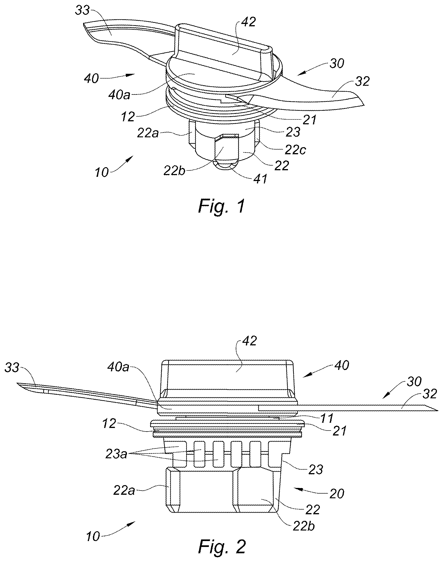
FIG. 1 is a perspective view of the blade holder according to a first embodiment of the invention,
FIG. 2 is a front view of the blade holder according to a second embodiment of the invention,
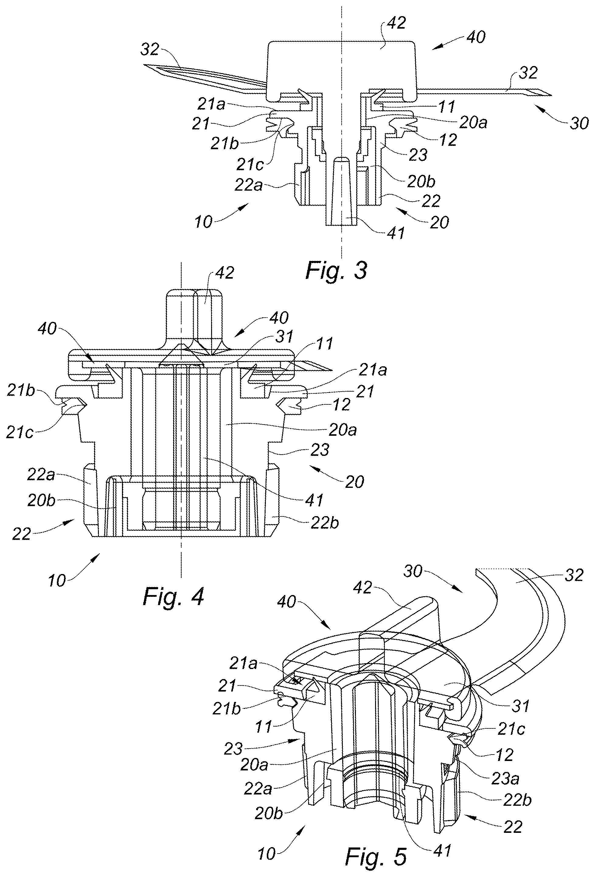
FIG. 3 is a front view, in longitudinal section, of the blade holder shown in FIG. 1,
FIG. 4 is a front sectional view of the blade holder shown in FIG. 2,
FIG. 5 is a perspective view, in longitudinal section, of the blade holder shown in FIG. 2,
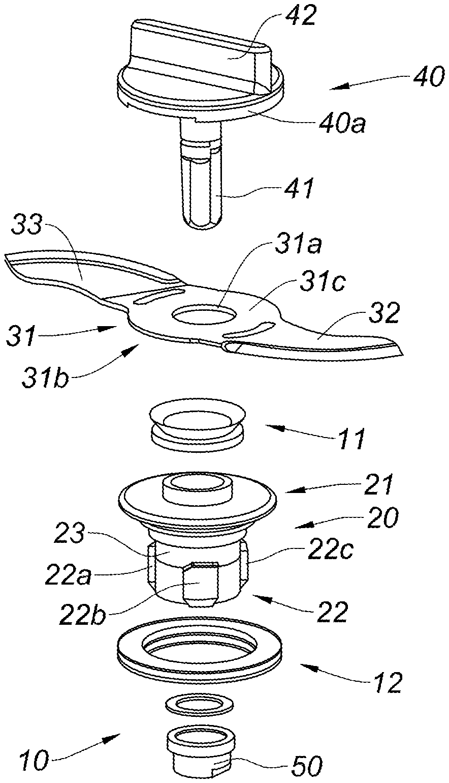
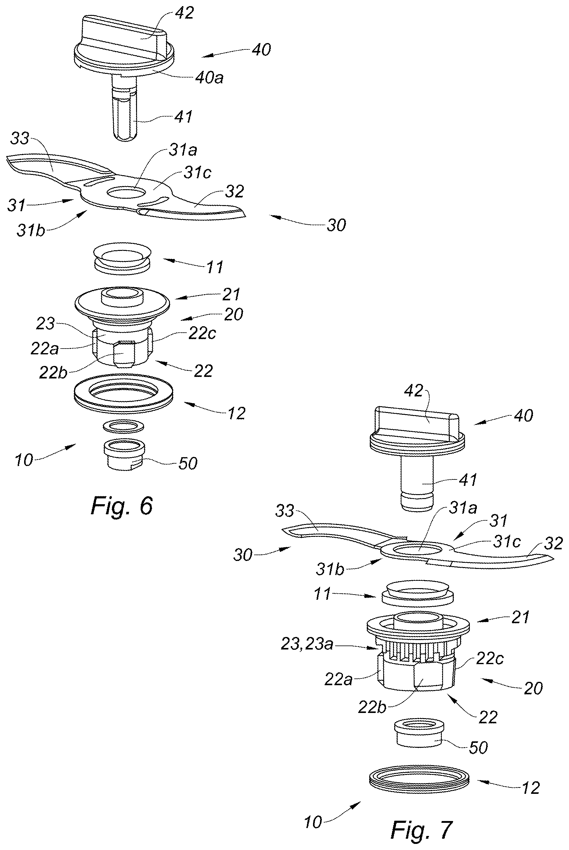
FIG. 6 is an exploded perspective view of the blade holder shown in FIG. 1,
FIG. 7 is an exploded perspective view of the blade holder shown in FIG. 2,
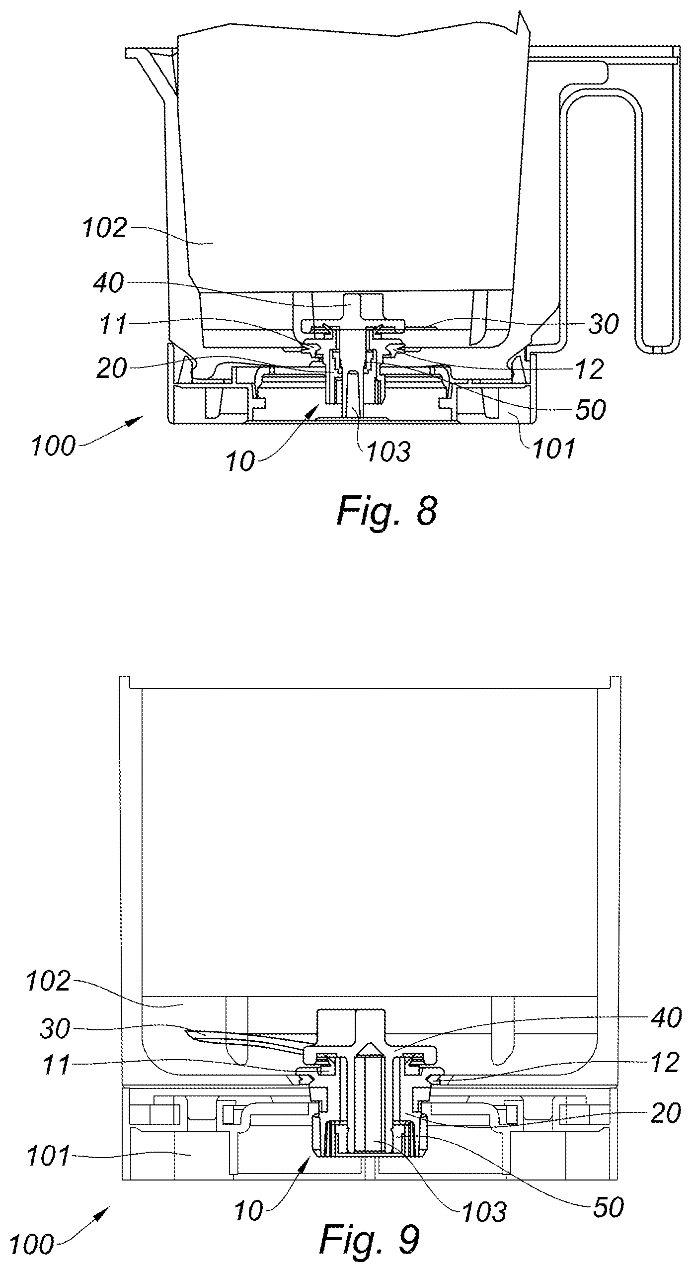
FIG. 8 is a sectional view of a food processor bowl comprising the blade holder according to the first embodiment,
FIG. 9 is a sectional view of a food processor bowl comprising the blade holder according to the second embodiment,
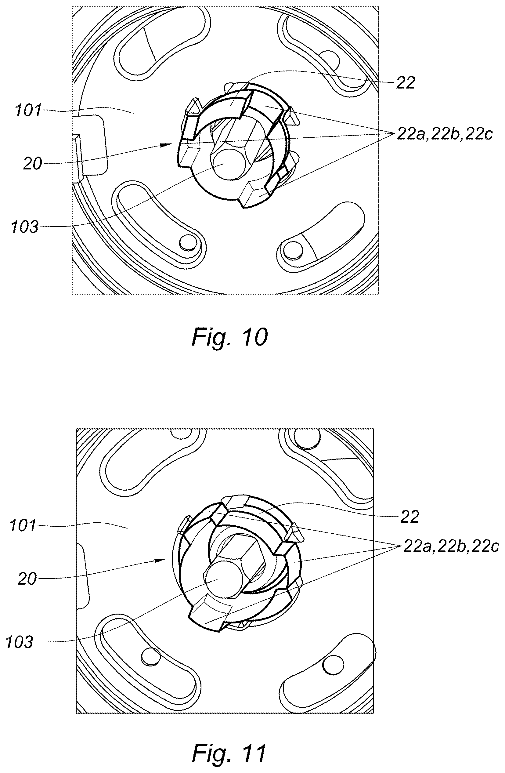
FIG. 10 is a sectional bottom view of the kitchen bowl in which the locking member is in the locked position, and
FIG. 11 is a sectional bottom view of the kitchen bowl in which the locking member is in the unlocked position.
Whichever the embodiment, the blade holder 10 according to the invention is a blade holder 10 for a food processor intended at least for preparing food. More particularly, the blade holder 10 is configured to be positioned removably in a food processor bowl 100 for preparing and/or cooking food, as is illustrated in FIGS. 8 and 9.
Whichever the embodiment, the blade holder 10 comprises at least one locking member 20 configured to lock the blade holder 10 in the bowl 100. The locking member 20 comprises at least one upper portion 21 comprising a first face 21a shaped so as to receive a first lip seal 11, as is illustrated in FIGS. 3, 4 and 5. According to the invention, the first seal 11 is configured to provide the leak tightness between the shaft 41 of the support 40 and the locking member 20.
As can be seen in particular in FIGS. 3, 4 and 5, the upper portion 21 of the locking member 20 additionally comprises a receiving groove 21c shaped to accommodate at least one second seal 12, said receiving groove 21c being arranged at a second face 21b of the upper portion 21, opposite the first face 21a.
Whichever the embodiment, the locking member 20 comprises a lower portion 22 shaped to cooperate with a part of the bowl 100 for preparing and/or cooking food, as is illustrated in FIGS. 8 to 11. As can be seen in particular in FIGS. 6 and 7, and whichever the embodiment, the lower portion 22 comprises at least one first deformation 22a and at least one second deformation 22b, each configured to cooperate with a complementary shape (not shown) provided on the bowl 100 for preparing and/or cooking food, the first deformation 22a and the second deformation 22b each being part of a bayonet locking system. In addition, the lower portion 22 comprises a third deformation 22c configured to cooperate with a complementary shape provided on the bowl 100 for preparing and/or cooking food, as is illustrated in FIGS. 10 and 11.
In the examples shown in FIGS. 6 and 7, and whichever the embodiment, the locking member 20 comprises a central portion 23 positioned between the upper portion 21 and the lower portion 22.
Whichever the embodiment, the locking member 20 comprises a first bore 20a shaped to accommodate the shaft 41 of the support 40, which will be described further below in the description, and a second bore 20b adjacent to the first bore 20a, the second bore 20b being shaped to accommodate a locking flange 50 configured to block the vertical translation of the shaft of the support, as is illustrated in particular in FIGS. 3 to 5, 8 and 9. In a variant not shown, the first bore can be a plain bearing.
Whichever the embodiment, the blade holder 10 additionally comprises at least one blade 30 comprising a central portion 31 from which a first knife 32 extends radially, the central portion 31 comprising a through-opening 31a configured to cooperate with the shaft 41 of a support 40 of the blade holder 10, the central portion 31 comprising a first face 31b, on which the support 40 is positioned, and a second face 31c, which is opposite the first face 31b and which is configured to cooperate with the first seal 11, positioned between the locking member 20 and the central portion 31 of the blade 30. In addition, and as illustrated in particular in FIGS. 1, 2, 3, 6 and 7, the blade 30 comprises a second knife 33 extending radially from the central portion 31 of the blade 30 in a different direction, preferably the opposite direction to that in which the first knife 32 extends.
Whichever the embodiment, the blade holder 10 additionally comprises at least one support 40 comprising at least one shaft 41 on a longitudinal axis X-X of the blade holder 10, the blade 30 being mounted on the support 40 about the shaft 41, as is illustrated in particular in FIGS. 6 and 7. The support 40 comprises a first portion 40a, on which the shaft 41 is provided, said first portion 40a being arranged opposite the second face 31c of the central portion 31 of the blade 30 in the assembled state of the blade holder 10. As can be seen in particular in FIGS. 1 and 2, the support 40 additionally comprises a gripping member 42 arranged on the first portion of the support 40 or, more particularly, the gripping member 42 is mounted on the shaft 41. As can be seen in the examples illustrated, the gripping member 42 is in the form of a projecting rib, preferably of rectangular shape, extending from the first portion 40a of the support 40 along the longitudinal axis X-X of the blade holder 10.
Whichever the embodiment, the shaft 41 is configured to be rotated with respect to the locking member 20 by a drive shaft 103 in the bowl 100, as is shown in FIGS. 8 and 9. Advantageously, the rotation can be effected by the blade holder 10 being mounted with play or else being mounted with a plain bearing.
Whichever the embodiment, the blade holder 10 comprises a second seal 12 configured to provide the leak tightness between the blade holder 10 and the bowl 100 for preparing and/or cooking food, as is illustrated in FIGS. 8 and 9 for example. In the examples illustrated in FIGS. 1 to 9, the second seal is a lip seal.
Of course, the invention is not limited to the embodiments described and shown in the attached figures. Modifications remain possible, especially from the point of view of the set-up of the various elements or by substitution of technical equivalents, without thereby departing from the scope of protection of the invention.
* * * * *
D00000
D00001
D00002
D00003
D00004
D00005
XML
uspto.report is an independent third-party trademark research tool that is not affiliated, endorsed, or sponsored by the United States Patent and Trademark Office (USPTO) or any other governmental organization. The information provided by uspto.report is based on publicly available data at the time of writing and is intended for informational purposes only.
While we strive to provide accurate and up-to-date information, we do not guarantee the accuracy, completeness, reliability, or suitability of the information displayed on this site. The use of this site is at your own risk. Any reliance you place on such information is therefore strictly at your own risk.
All official trademark data, including owner information, should be verified by visiting the official USPTO website at www.uspto.gov. This site is not intended to replace professional legal advice and should not be used as a substitute for consulting with a legal professional who is knowledgeable about trademark law.