Heat pump and water heater
Taras , et al. December 22, 2
U.S. patent number 10,871,314 [Application Number 15/634,434] was granted by the patent office on 2020-12-22 for heat pump and water heater. This patent grant is currently assigned to Climate Master, Inc.. The grantee listed for this patent is Climate Master, Inc.. Invention is credited to Michael S. Privett, Jeremy R. Smith, Michael F. Taras.


| United States Patent | 10,871,314 |
| Taras , et al. | December 22, 2020 |
Heat pump and water heater
Abstract
An embodiment of the instant disclosure comprises a reversible heat pump and water heating system for conditioning a space and heating water. The system comprises a refrigerant circuit that includes a compressor, a source heat exchanger, a space heat exchanger, and an expansion device. A 4-way reversing valve alternates between heating and cooling modes of operation. The system includes a heat exchanger for heating water in the water heating loop, and a 3-way valve that either actuates the refrigerant flow through the water heater heat exchanger or bypasses at least a portion of the refrigerant flow around the water heater heat exchanger. The heat pump system is operable in at least five modes--space heating only, space cooling only, water heating only, and either space heating or space cooling combined with water heating. Use of a modulating 3-way valve allows the amount of the refrigerant flow through the water heating heat exchanger to be adjusted to precisely match space conditioning and water heating demands and stable operation of the heat pump system. Either of the space and source heat exchangers may be bypassed and deactivated to reduce the heat pump system power consumption.
| Inventors: | Taras; Michael F. (Oklahoma City, OK), Privett; Michael S. (Tuttle, OK), Smith; Jeremy R. (Edmond, OK) | ||||||||||
|---|---|---|---|---|---|---|---|---|---|---|---|
| Applicant: |
|
||||||||||
| Assignee: | Climate Master, Inc. (Oklahoma
City, OK) |
||||||||||
| Family ID: | 60893261 | ||||||||||
| Appl. No.: | 15/634,434 | ||||||||||
| Filed: | June 27, 2017 |
Prior Publication Data
| Document Identifier | Publication Date | |
|---|---|---|
| US 20180010829 A1 | Jan 11, 2018 | |
Related U.S. Patent Documents
| Application Number | Filing Date | Patent Number | Issue Date | ||
|---|---|---|---|---|---|
| 62359798 | Jul 8, 2016 | ||||
| Current U.S. Class: | 1/1 |
| Current CPC Class: | F25B 13/00 (20130101); F25B 41/20 (20210101); F25B 6/04 (20130101); F25B 30/02 (20130101); F25B 2339/047 (20130101); F25B 2313/0233 (20130101); F25B 2313/02321 (20130101); F25B 2400/0403 (20130101); F25B 2600/2501 (20130101) |
| Current International Class: | F25B 30/02 (20060101); F25B 13/00 (20060101); F25B 41/04 (20060101); F25B 6/04 (20060101) |
References Cited [Referenced By]
U.S. Patent Documents
| 3460353 | August 1969 | Ogata et al. |
| 3916638 | November 1975 | Schmidt |
| 3938352 | February 1976 | Schmidt |
| 4072187 | February 1978 | Lodge |
| 4173865 | November 1979 | Sawyer |
| 4179894 | December 1979 | Hughes |
| 4299098 | November 1981 | Derosier |
| 4399664 | August 1983 | Derosier |
| 4441901 | April 1984 | Endoh |
| 4493193 | January 1985 | Fisher |
| 4528822 | July 1985 | Glamm |
| 4538418 | September 1985 | Lawrence et al. |
| 4575001 | March 1986 | Oskarsson et al. |
| 4592206 | June 1986 | Yamazaki et al. |
| 4598557 | July 1986 | Robinson et al. |
| 4645908 | February 1987 | Jones |
| 4646538 | March 1987 | Blackshaw et al. |
| 4693089 | September 1987 | Bourne |
| 4727727 | March 1988 | Reedy |
| 4766734 | August 1988 | Dudley |
| 4776180 | October 1988 | Patton et al. |
| 4796437 | January 1989 | James |
| 4798059 | January 1989 | Morita |
| 4835976 | June 1989 | Torrence |
| 4856578 | August 1989 | McCahill |
| 4893476 | January 1990 | Bos et al. |
| 4920757 | May 1990 | Gazes et al. |
| 4924681 | May 1990 | De Vit et al. |
| 4938032 | July 1990 | Mudford |
| 5038580 | August 1991 | Hart |
| 5044425 | September 1991 | Tatsumi et al. |
| 5081848 | January 1992 | Rawlings et al. |
| 5088296 | February 1992 | Hamaoka |
| 5099651 | March 1992 | Fischer |
| 5136855 | August 1992 | Lenarduzzi |
| 5172564 | December 1992 | Reedy |
| 5187944 | February 1993 | Jarosch |
| 5224357 | July 1993 | Galiyano et al. |
| 5305822 | April 1994 | Kogetsu et al. |
| 5309732 | May 1994 | Sami |
| 5323844 | June 1994 | Sumitani et al. |
| 5339890 | August 1994 | Rawlings |
| 5355688 | October 1994 | Rafalovich et al. |
| 5372016 | December 1994 | Rawlings |
| 5438846 | August 1995 | Datta |
| 5461876 | October 1995 | Dressler |
| 5465588 | November 1995 | McCahill et al. |
| 5477914 | December 1995 | Rawlings |
| 5497629 | March 1996 | Rafalovich et al. |
| 5507337 | April 1996 | Rafalovich et al. |
| 5533355 | July 1996 | Rawlings |
| 5564282 | October 1996 | Kaye |
| 5613372 | March 1997 | Beal et al. |
| 5619864 | April 1997 | Reedy |
| 5628200 | May 1997 | Pendergrass |
| 5651265 | July 1997 | Grenier |
| 5669224 | September 1997 | Lenarduzzi |
| 5689966 | November 1997 | Zess et al. |
| 5729985 | March 1998 | Yoshihara et al. |
| 5758514 | June 1998 | Genung et al. |
| 5802864 | September 1998 | Yarbrough et al. |
| 5927088 | July 1999 | Shaw |
| 6032472 | March 2000 | Heinrichs et al. |
| 6070423 | June 2000 | Hebert |
| 6082125 | July 2000 | Savtchenko |
| 6123147 | September 2000 | Pittman |
| 6149066 | November 2000 | Perry et al. |
| 6167715 | January 2001 | Hebert |
| 6227003 | May 2001 | Smolinsky |
| 6253564 | July 2001 | Yarbrough |
| 6347527 | February 2002 | Bailey et al. |
| 6385983 | May 2002 | Sakki et al. |
| 6418745 | July 2002 | Ratliff |
| 6434960 | August 2002 | Rousseau |
| 6474087 | November 2002 | Lifson |
| 6536221 | March 2003 | James |
| 6655164 | December 2003 | Rogstam |
| 6662864 | December 2003 | Burk et al. |
| 6694750 | February 2004 | Lifson et al. |
| 6729151 | May 2004 | Thompson |
| 6751972 | June 2004 | Jungwirth |
| 6804975 | October 2004 | Park |
| 6817205 | November 2004 | Lifson et al. |
| 6826921 | December 2004 | Uselton |
| 6857285 | February 2005 | Hebert |
| 6892553 | May 2005 | Lifson et al. |
| 6915656 | July 2005 | Ratliff |
| 6931879 | August 2005 | Wiggs |
| 6938438 | September 2005 | Lifson et al. |
| 6941770 | September 2005 | Taras et al. |
| 7000423 | February 2006 | Lifson et al. |
| 7059151 | June 2006 | Taras et al. |
| 7114349 | October 2006 | Lifson et al. |
| 7150160 | December 2006 | Herbert |
| 7155922 | January 2007 | Harmon et al. |
| 7185505 | March 2007 | Kamimura |
| RE39597 | May 2007 | Rousseau |
| 7210303 | May 2007 | Zhang et al. |
| 7228707 | June 2007 | Lifson et al. |
| 7234311 | June 2007 | Lifson et al. |
| 7254955 | August 2007 | Otake et al. |
| 7263848 | September 2007 | Bhatti |
| 7272948 | September 2007 | Taras et al. |
| 7275385 | October 2007 | Abel et al. |
| 7325414 | February 2008 | Taras et al. |
| 7484374 | February 2009 | Pham et al. |
| 7617697 | November 2009 | McCaughan |
| 7654104 | February 2010 | Groll et al. |
| 7716943 | May 2010 | Seefeldt |
| 7770405 | August 2010 | Dillon |
| 7823404 | November 2010 | Hanson |
| 7845190 | December 2010 | Pearson |
| 7854137 | December 2010 | Lifson et al. |
| 7856834 | December 2010 | Haley |
| 7913501 | March 2011 | Ellis et al. |
| 7937960 | May 2011 | Matsui |
| 7958737 | June 2011 | Lifson et al. |
| 7975495 | July 2011 | Voorhis et al. |
| 7975506 | July 2011 | James et al. |
| 7997092 | August 2011 | Lifson et al. |
| 8037713 | October 2011 | Haley et al. |
| 8074459 | December 2011 | Murakami et al. |
| 8079228 | December 2011 | Lifson et al. |
| 8079229 | December 2011 | Lifson et al. |
| 8082751 | December 2011 | Wiggs |
| 8136364 | March 2012 | Lifson et al. |
| 8191376 | June 2012 | Fox et al. |
| 8220531 | July 2012 | Murakami et al. |
| 8418482 | April 2013 | Bush et al. |
| 8418486 | April 2013 | Taras et al. |
| 8424326 | April 2013 | Mitra et al. |
| 8459052 | June 2013 | Bush et al. |
| 8528359 | September 2013 | Lifson et al. |
| 8561425 | October 2013 | Mitra et al. |
| 8650893 | February 2014 | Hanson |
| 8733429 | May 2014 | Harrison et al. |
| 8756943 | June 2014 | Chen et al. |
| 8769982 | July 2014 | Ignatiev et al. |
| 8984903 | March 2015 | Itoh et al. |
| 9052125 | June 2015 | Dostal |
| 9562700 | February 2017 | Watanabe |
| 10072856 | September 2018 | Akin et al. |
| 10118462 | November 2018 | Kohigashi et al. |
| 10119738 | November 2018 | Hammond et al. |
| 10345004 | July 2019 | Hern et al. |
| 2003/0221445 | December 2003 | Smolinsky |
| 2006/0010908 | January 2006 | Taras et al. |
| 2006/0218949 | October 2006 | Ellis et al. |
| 2006/0225445 | October 2006 | Lifson et al. |
| 2007/0074536 | April 2007 | Bai |
| 2007/0289319 | December 2007 | Kim et al. |
| 2007/0295477 | December 2007 | Mueller et al. |
| 2008/0016895 | January 2008 | Kim et al. |
| 2008/0041072 | February 2008 | Seefeldt |
| 2008/0173034 | July 2008 | Shaw |
| 2008/0196418 | August 2008 | Lifson et al. |
| 2008/0197206 | August 2008 | Murakami et al. |
| 2008/0209930 | September 2008 | Taras et al. |
| 2008/0256975 | October 2008 | Lifson et al. |
| 2008/0282718 | November 2008 | Beagle |
| 2008/0296396 | December 2008 | Corroy et al. |
| 2008/0302113 | December 2008 | Yin et al. |
| 2008/0302118 | December 2008 | Chen et al. |
| 2008/0302129 | December 2008 | Mosemann et al. |
| 2008/0307813 | December 2008 | Lifson et al. |
| 2009/0107656 | April 2009 | Marois |
| 2009/0208331 | August 2009 | Haley et al. |
| 2009/0294097 | December 2009 | Rini et al. |
| 2009/0314014 | December 2009 | Ericsson |
| 2010/0005831 | January 2010 | Vaisman et al. |
| 2010/0024470 | February 2010 | Lifson et al. |
| 2010/0058781 | March 2010 | Lifson et al. |
| 2010/0064710 | March 2010 | Slaughter |
| 2010/0064722 | March 2010 | Taras |
| 2010/0077788 | April 2010 | Lewis |
| 2010/0114384 | May 2010 | Maxwell |
| 2010/0132399 | June 2010 | Mitra et al. |
| 2010/0199715 | August 2010 | Lifson et al. |
| 2010/0251750 | October 2010 | Lifson et al. |
| 2010/0281894 | November 2010 | Huff |
| 2010/0287969 | November 2010 | Ueda et al. |
| 2010/0326100 | December 2010 | Taras et al. |
| 2011/0023515 | February 2011 | Kopko et al. |
| 2011/0036119 | February 2011 | Fujimoto et al. |
| 2011/0041523 | February 2011 | Taras et al. |
| 2011/0061413 | March 2011 | Setoguchi |
| 2011/0079032 | April 2011 | Taras et al. |
| 2011/0088426 | April 2011 | Lochtefeld |
| 2011/0094248 | April 2011 | Taras et al. |
| 2011/0094259 | April 2011 | Lifson et al. |
| 2011/0132007 | June 2011 | Weyna et al. |
| 2011/0174014 | July 2011 | Scarcella et al. |
| 2011/0203299 | August 2011 | Jing et al. |
| 2011/0209490 | September 2011 | Mijanovic et al. |
| 2011/0259025 | October 2011 | Noh |
| 2011/0289950 | December 2011 | Kim et al. |
| 2011/0289952 | December 2011 | Kim et al. |
| 2012/0011866 | January 2012 | Scarcella et al. |
| 2012/0067965 | March 2012 | Rajasekaran et al. |
| 2012/0103005 | May 2012 | Kopko et al. |
| 2012/0198867 | August 2012 | Ng et al. |
| 2012/0205077 | August 2012 | Zinger et al. |
| 2012/0247134 | October 2012 | Gurin |
| 2012/0291460 | November 2012 | Aoyagi |
| 2013/0014451 | January 2013 | Russell et al. |
| 2013/0031934 | February 2013 | Huff et al. |
| 2013/0098085 | April 2013 | Judge et al. |
| 2013/0104574 | May 2013 | Dempsey |
| 2013/0180266 | July 2013 | Bois |
| 2013/0269378 | October 2013 | Wong |
| 2013/0305756 | November 2013 | Gomes et al. |
| 2014/0013782 | January 2014 | Kopko et al. |
| 2014/0013788 | January 2014 | Kopko et al. |
| 2014/0033753 | February 2014 | Lu et al. |
| 2014/0033755 | February 2014 | Wong |
| 2014/0053585 | February 2014 | Huff |
| 2014/0060101 | March 2014 | Styles et al. |
| 2014/0123689 | May 2014 | Ellis et al. |
| 2014/0245770 | September 2014 | Chen et al. |
| 2014/0260392 | September 2014 | Hawkins |
| 2015/0052937 | February 2015 | Hung |
| 2015/0059373 | March 2015 | Maiello et al. |
| 2015/0204586 | July 2015 | Burg |
| 2017/0010029 | January 2017 | Reytblat et al. |
| 2017/0227250 | August 2017 | Karamanos |
| 2018/0128506 | May 2018 | Taras et al. |
| 2018/0313555 | November 2018 | Henderson |
| 2019/0178509 | June 2019 | Taras et al. |
| 1178268 | Nov 1984 | CA | |||
| 1987397 | Jun 2007 | CN | |||
| 201944952 | Aug 2011 | CN | |||
| 102353126 | Feb 2012 | CN | |||
| 203231582 | Oct 2013 | CN | |||
| 103471275 | Dec 2013 | CN | |||
| 203396155 | Jan 2014 | CN | |||
| 203432025 | Feb 2014 | CN | |||
| 134015 | Mar 1985 | EP | |||
| 1983275 | Oct 2008 | EP | |||
| 2000046417 | Feb 2000 | JP | |||
| 2000274786 | Oct 2000 | JP | |||
| 2000314563 | Nov 2000 | JP | |||
| 2001248931 | Sep 2001 | JP | |||
| 100963221 | Jun 2010 | KR | |||
| 9600370 | Jan 1996 | WO | |||
| 2001/90663 | Nov 2001 | WO | |||
| 2006/033782 | Mar 2006 | WO | |||
| 2008/045086 | Apr 2008 | WO | |||
| 2008/048252 | Apr 2008 | WO | |||
| 2010/005918 | Jan 2010 | WO | |||
| 2010/054498 | May 2010 | WO | |||
| 2010/104709 | Sep 2010 | WO | |||
| 2013/142760 | Sep 2013 | WO | |||
| 2014/031559 | Feb 2014 | WO | |||
| 2014/031708 | Feb 2014 | WO | |||
Other References
|
Honeywell, VFF1, VFF2, VFF3, VFF6 Resilient Seat Butterfly Valves with Flanged Connections Jan. 2013, p. 1, 1st column, last paragraph. (Year: 2013). cited by examiner . International Search Report and Written Opinion issued in International Application No. PCT/US2013/033433 dated Aug. 9, 2013 (11 Pages). cited by applicant . International Preliminary Report on Patentability issued in International Application No. PCT/US2013/033433 dated Sep. 23, 2014 (7 Pages). cited by applicant . Third Party Submission dated Nov. 10, 2014 filed in U.S. Appl. No. 13/848,342 (13 Pages). cited by applicant . Michael F. Taras, "Reheat Which Concept is Best," ASHRAE Journal: 35-40 (Dec. 2004) (7 pages). cited by applicant . "Heat Pump Mechanics" http://www.geo4va.vt.edu/A3/A3.htm#A3sec3c (Accessed Apr. 20, 2011) (19 pages). cited by applicant . "Heat pumps in residential and commercial buildings" http://www.heatpumpcentre.org/en/aboutheatpumps/heatpumpsinresidential/Si- dor/default.aspx (Accessed Apr. 20, 2011) (2 pages). cited by applicant . Korean Intellectual Property Office, International Search Report in International Application No. PCT/US2009/049734 (dated Jan. 20, 2010) (2 pages). cited by applicant . Korean Intellectual Property Office, International Search Report in International Application No. PCT/US2010/026010 (dated Sep. 28, 2010) (2 pages). cited by applicant . Murphy et al., "Air-Source Integrated Heat Pump for Net-Zero-Energy Houses Technology Status Report," Oak Ridge National Laboratory, ORNL-TM-2007-112 (Jul. 2007) (93 pages). cited by applicant . Murphy et al., "Ground-Source Integrated Heat Pump for Net-Zero-Energy Houses Technology Status Report," Oak Ridge National Laboratory, ORNL-TM-2007-177 (Dec. 2007) (78 pages). cited by applicant . "134-XS and 134-S Series Compressors ECOnomizer (EA-12-03-E)," 134-XS and 134-S series--Application and Maintenance Manual, Technical report EA1203E, RefComp Refrigerant Compressors, undated but believed to be publicly available at least as early as Mar. 2014 (4 pages). cited by applicant . B.P. Rasmussen et al., "Model-Driven System Identification of Transcritical Vapor Compression Systems," IEEE Transactions on Control Systems Technology, May 2005, pp. 444-451, vol. 13 (8 pages). cited by applicant . "Economized Vapor Injection (EVI) Compressors," Emerson Climate Technologies Application Engineering Bulletin AE4-1327 R2, Revised Sep. 2006 (9 pages). cited by applicant . Ekaterina Vi Nogradova, "Economizers in Chiller Systems," Bachelor's Thesis, Mikkelin Ammattikorkeakoulu, Nov. 2012 (50 pages). cited by applicant . "Enhanced Vapour Injection (EVI) for ZH*KVE Scroll Compressors," Emerson Climate Technologies--Technical Information, C7.4.3/1107-0512/E, May 2012 (10 pages). cited by applicant . Haraldsson et al., "Measurement of Performance and Evaluation of a Heat Pump with Scroll Compressor EVI and Economizer," Lunds Institute of Technology, 2006 (4 pages). cited by applicant . Lund et al., "Geothermal (Ground-Source Heat Pumps--A World Overview," GHC Bulletin, Sep. 2004 (edited and updated version of the article from Renewal Energy World, (Jul.-Aug. 2003), vol. 6 No. 4) (10 pages). cited by applicant . John P. Elson et al., "Scroll Technology: An Overview of Past, Present and Future Developments," International Compressor Engineering Conference, 2008, Paper 1871 (9 pages). cited by applicant . Tolga N. Aynur, "Variable Refrigerant Flow Systems: A Review, Energy and Buildings," Jan. 2010, pp. 1106-1112, vol. 42 (7 pages). cited by applicant . Wei Yang et al., "The Design Method of U-Bend Geothermal Heat Exchanger of DX-GCHP in Cooling Model," IEEE, 2011, pp. 3635-3637 (English Abstract) (3 pages). cited by applicant. |
Primary Examiner: Jules; Frantz F
Assistant Examiner: Nouketcha; Lionel
Attorney, Agent or Firm: Neal, Gerber & Eisenberg LLP Williams; Thomas E.
Parent Case Text
CROSS-REFERENCE TO RELATED APPLICATIONS
This application claims the benefit of U.S. Provisional Application No. 62/359,798 filed on Jul. 8, 2016, which is incorporated by reference herein in its entirety.
Claims
What is claimed is:
1. A heat pump system for conditioning air in a space, comprising: a variable speed compressor configured to circulate a refrigerant through a refrigerant circuit, the variable speed compressor having a discharge outlet port and an inlet suction port; a refrigerant-to-liquid heat exchanger configured to operate as either a condenser or an evaporator to exchange heat between the refrigerant and a heat exchange liquid; a refrigerant-to-air heat exchanger configured to operate as either a condenser or an evaporator to exchange heat between the refrigerant and the air, the air conditioned thereby for use in the space; a bi-directional expansion valve disposed on the refrigerant circuit and positioned between the refrigerant-to-liquid heat exchanger and the refrigerant-to-air heat exchanger; a desuperheater heat exchanger configured to operate as a condenser to exchange heat between the refrigerant and water to heat the water; a 3-way valve disposed along the refrigerant circuit between the variable speed compressor and the desuperheater heat exchanger, wherein the 3-way valve is connected to a desuperheater bypass circuit to permit the refrigerant to bypass the desuperheater heat exchanger, wherein the 3-way valve is configured to selectively direct the refrigerant from the variable speed compressor to either the desuperheater heat exchanger or the desuperheater bypass circuit; a reversing valve disposed along the refrigerant circuit, the reversing valve including a first port configured to receive the refrigerant from the desuperheater bypass circuit and/or from the desuperheater heat exchanger, a second port connected to the inlet suction port of the variable speed compressor, a third port connected to the refrigerant-to-air heat exchanger, and a fourth port connected to the refrigerant-to-liquid heat exchanger, wherein, in a space cooling mode, the reversing valve is configured to convey the refrigerant from the first port to the fourth port and from the second port to the third port to cause the refrigerant to flow to the refrigerant-to-liquid heat exchanger configured to operate as a condenser, through the bi-directional expansion valve, and to the refrigerant-to-air heat exchanger configured to operate as an evaporator to cool the air for use in the space, and wherein, in a space heating mode, the reversing valve is configured to convey the refrigerant from the first port to the third port and from the second port to the fourth port to cause the refrigerant to flow to the refrigerant-to-air heat exchanger configured to operate as a condenser, through the bi-directional expansion valve, and to the refrigerant-to-liquid heat exchanger configured to operate as an evaporator to heat the air for use in the space.
2. The heat pump system of claim 1, including a fan driven by a variable speed motor, the fan configured to flow air over a portion of the refrigerant-to-air heat exchanger.
3. The heat pump system of claim 1, wherein the bi-directional expansion valve is a fixed orifice valve, a mechanical valve, or an electronic valve.
4. The heat pump system of claim 1, wherein the desuperheater heat exchanger is a second refrigerant-to-liquid heat exchanger configured to exchange heat between the refrigerant in the refrigerant circuit and the water in a water storage loop.
5. The heat pump system of claim 4, including a variable speed water pump for circulating heated water in the water storage loop and through the desuperheater heat exchanger.
6. The heat pump system of claim 1, including a variable speed pump disposed on a source loop for circulating the heat exchange liquid through the refrigerant-to-liquid heat exchanger.
7. The heat pump system of claim 1, including a controller configured to control operation of the variable speed compressor, the reversing valve, the 3-way valve, the bi-directional expansion valve, a first variable speed pump for circulating the water through the desuperheater heat exchanger, and a second variable speed pump for circulating the heat exchange liquid through the refrigerant-to-liquid heat exchanger.
8. The heat pump system of claim 1, wherein the reversing valve and the 3-way valve are configured to alter the flow of the refrigerant to change a mode of operation between the space cooling mode, a space cooling and water heating mode, the space heating mode, a space heating and water heating mode, and a primary water heating mode.
9. The heat pump system of claim 8, wherein to operate in the space cooling mode, the 3-way valve is configured to direct the refrigerant from the variable speed compressor to the reversing valve via the desuperheater bypass circuit; the reversing valve is configured to direct the refrigerant, via the first port and the fourth port, to the refrigerant-to-liquid heat exchanger that is configured to operate as a condenser, the bi-directional expansion valve is configured to receive the refrigerant from the refrigerant-to-liquid heat exchanger, the refrigerant-to-air heat exchanger is configured as an evaporator and receive the refrigerant from the bi-directional expansion valve, and the reversing valve is configured to receive, via the third port, the refrigerant from the refrigerant-to-air heat exchanger and direct, via the second port, the refrigerant to the variable speed compressor.
10. The heat pump system of claim 8, wherein to operate in the space cooling and water heating mode, the 3-way valve is configured to direct the refrigerant from the variable speed compressor to the desuperheater heat exchanger, the reversing valve is configured to receive, via the first port, the refrigerant from the desuperheater heat exchanger and direct, via the fourth port, the refrigerant to the refrigerant-to-liquid heat exchanger that is configured to operate as a condenser, the bi-directional expansion valve is configured to receive the refrigerant from the refrigerant-to-liquid heat exchanger, the refrigerant-to-air heat exchanger is configured to operate as an evaporator and receive the refrigerant from the bi-directional expansion valve, and the reversing valve is configured to receive, via the third port, the refrigerant from the refrigerant-to-air heat exchanger and direct, via the second port, the refrigerant to the variable speed compressor.
11. The heat pump system of claim 8, wherein to operate in the space heating mode, the 3-way valve is configured to direct the refrigerant from the variable speed compressor to the reversing valve via the desuperheater bypass circuit; the reversing valve is configured to direct the refrigerant, via the first port and the third port, to the refrigerant-to-air heat exchanger that is configured to operate as a condenser, the bi-directional expansion valve is configured to receive the refrigerant from the refrigerant-to-air heat exchanger, the refrigerant-to-liquid heat exchanger is configured to operate as an evaporator and receive the refrigerant from the bi-directional expansion valve, and the reversing valve is configured to receive, via the fourth port, the refrigerant from the refrigerant-to-liquid heat exchanger and direct, via the second port, the refrigerant to the variable speed compressor.
12. The heat pump system of claim 8, wherein to operate in the space heating and water heating mode, the 3-way valve is configured to direct the refrigerant from the variable speed compressor to the desuperheater heat exchanger, the reversing valve is configured to receive, via the first port, the refrigerant from the desuperheater heat exchanger and direct, via the third port, the refrigerant to the refrigerant-to-air heat exchanger that is configured to operate as a condenser, the bi-directional expansion valve that is configured to receive the refrigerant from the refrigerant-to-air heat exchanger, the refrigerant-to-liquid heat exchanger is configured to operate as an evaporator and receive the refrigerant from the bi-directional expansion valve, the reversing valve is configured to receive, via the fourth port, the refrigerant from the refrigerant-to-liquid heat exchanger and direct, via the second port, the refrigerant to the variable speed compressor.
13. The heat pump system of claim 8, wherein to operate in the primary water heating mode, the 3-way valve is configured to direct the refrigerant from the variable speed compressor to the desuperheater heat exchanger that is configured to operate as a desuperheater, condenser, and subcooler, the reversing valve is configured to receive, via the first port, the refrigerant from the desuperheater heat exchanger and direct, via the third port, the refrigerant toward the refrigerant-to-air heat exchanger, the bi-directional expansion valve is configured to subsequently receive the refrigerant, the refrigerant-to-liquid heat exchanger is configured to operate as an evaporator and receive the refrigerant from the bi-directional expansion valve, and the reversing valve is configured to receive, via the fourth port, the refrigerant from the refrigerant-to-liquid heat exchanger and direct, via the second port, the refrigerant to the variable speed compressor.
14. The heat pump system of claim 8, including a second 3-way valve connected to a refrigerant-to-liquid heat exchanger bypass circuit to permit the refrigerant to bypass the refrigerant-to-liquid heat exchanger in the space cooling mode and water heating mode.
15. The heat pump system of claim 14, including a third 3-way valve connected to a refrigerant-to-air heat exchanger bypass circuit to permit the refrigerant to bypass the refrigerant-to-air heat exchanger in the space heating and water heating mode and in the water heating mode.
Description
STATEMENT REGARDING FEDERALLY SPONSORED RESEARCH AND DEVELOPMENT
This application is not federally sponsored.
FIELD
The instant disclosure relates generally to heating, ventilation, and air conditioning systems and methods and, more particularly but without limitation, to heat pump systems and control methods.
BACKGROUND
Modern reversible heat pump systems are designed with improved efficiency and reduced energy consumption to comply with the heating, air conditioning, and ventilation industry trends, sustainability initiatives, and governmental regulations to increase efficiency thresholds in both heating and cooling modes of operation. In particular, integration of the water heating option into the heat pump design in commercial and residential applications (in place of electric or gas heaters) is becoming increasingly popular and allows for more efficient energy utilization to reduce an overall building waste heat disposal. However, due to limitations imposed by the system design and operating conditions, the cycle schematics that integrate the water heating option known to date are relatively costly, complex, inflexible in operation, and less reliable. They also employ extra refrigerant charge and often lack desirable control options and features. There exists a need, therefore, to solve these problems.
SUMMARY
A heat pump and water heating system for conditioning a space and heating water is disclosed, comprising: (a) a heat pump refrigerant circuit comprising a refrigerant circuit that fluidly interconnects: (i) a compressor having a discharge outlet and a suction port; (ii) a source heat exchanger; (iii) a space heat exchanger; (iv) an expansion valve positioned between the space heat exchanger and the source heat exchanger; (v) a reversing valve positioned on the discharge side of the compressor and configured to alternately direct refrigerant flow from the discharge outlet of the compressor to the one of the source heat exchanger and the space heat exchanger and to alternately return flow from the other of the source heat exchanger and the space heat exchanger to the suction port of the compressor; (vi) a water heater heat exchanger positioned on the discharge side of the compressor between the compressor and the reversing valve; (vii) a water heating valve on the discharge side of the compressor; (viii) a water heater heat exchanger bypass line connecting the water heating valve and the refrigerant line between the water heater heat exchanger and the reversing valve and configured to alternately direct at least a portion of refrigerant from the discharge outlet of the compressor to one of the bypass line or the water heater heat exchanger; and (b) controls for operating the heat pump and water heating system in response to the space conditioning demands and the water heating demands.
The water heating valve may be a regulating valve and the system controls may operate the regulating valve in response to the water heating demands to adjust the relative amount of refrigerant flow directed through the water heater heat exchanger and the water heater heat exchanger bypass line. The water heating valve may be a rapid cycle valve and the system controls may operate the rapid cycle valve in response to the water heating demands to adjust the relative amount of refrigerant flow directed through the water heater heat exchanger and the water heater heat exchanger bypass line. The water heating valve may be a pulse width modulation valve and the system controls may operate the pulse width modulation modulating valve in response to the water heating demands to adjust the relative amount of refrigerant flow directed through the water heater heat exchanger and the water heater heat exchanger bypass line.
The water heating valve may be a 3-way valve. The water heating valve may be a pair of conventional 2-way valves. The water heating valve may be positioned upstream the water heating heat exchanger with respect to the refrigerant flow. A check valve may be positioned downstream the water heating heat exchanger with respect to refrigerant flow. The water heating valve may be positioned downstream the water heating heat exchanger with respect to refrigerant flow.
The heat pump and water heating system may include a bypass circuit around the source heat exchanger, where the bypass circuit around the source heat exchanger may include a bypass refrigerant line and a bypass valve. The heat pump and water heating system may include a bypass circuit around the space heat exchanger, where the bypass circuit around the space heat exchanger may include a bypass refrigerant line and a bypass valve. The heat pump system may be one of water-to-air, water-to-water, air-to-water, and air-to-air system. The heat pump and water heating system may include air and water circulation devices assisting in heat interaction for space conditioning and water heating, where at least one of the compressor and the water circulating or air circulating devices may be a variable capacity device.
A method is disclosed for operating a heat pump system for conditioning a space and heating water wherein the heat pump system comprises a water heater heat exchanger, a water heater heat exchanger bypass line, and a water heater valve configured to direct refrigerant from the discharge side of the compressor in the heat pump system in selected relative percentages through the water heater heat exchanger and the water heater heat exchanger bypass line. The method includes operating the water heater valve in response to the space conditioning and water heating demands to adjust the selected relative percentages of refrigerant being directed through the water heater heat exchanger and the water heater heat exchanger bypass line.
The selected relative percentages of the refrigerant being directed through the water heater heat exchanger and the water heater heat exchanger bypass line may be in the range from zero percent to one hundred percent. The space conditioning demand may take a priority over water heating demand.
The water heating valve may be a regulating valve, and the method may include operating the regulating valve in response to the water heating demands of the space to adjust the relative amount of refrigerant flow directed through the water heater heat exchanger and the water heater heat exchanger bypass line. The water heating valve may be a rapid cycle valve, and the method may include operating the rapid cycle valve in response to the water heating demands of the space to adjust the relative amount of refrigerant flow directed through the water heater heat exchanger and the water heater heat exchanger bypass line. The water heating valve may be a pulse width modulation valve, and the method may include operating the pulse width modulation valve in response to the water heating demands of the space to adjust the relative amount of refrigerant flow directed through the water heater heat exchanger and the water heater heat exchanger bypass line. The water heating valve may be a 3-way valve. The water heating valve may be a pair of conventional 2-way valves.
The water heating valve may be positioned upstream of the water heating heat exchanger with respect to the refrigerant flow. The check valve may be positioned downstream of the water heating heat exchanger with respect to refrigerant flow. The water heating valve may be positioned downstream of the water heating heat exchanger with respect to refrigerant flow. The heat pump system may include a bypass circuit around the source heat exchanger and the bypass circuit around the source heat exchanger may include a bypass refrigerant line and a bypass valve. The heat pump system may include a bypass circuit around the space heat exchanger and the bypass circuit around the space heat exchanger may include a bypass refrigerant line and a bypass valve. The heat pump system may be one of water-to-air, water-to-water, air-to-water, and air-to-air system. The heat pump system may include air and water circulation devices assisting in heat interaction for space conditioning and water heating and the at least one of the compressor and the water circulating or air circulating devices may be a variable capacity device.
BRIEF DESCRIPTION OF THE DRAWINGS
The accompanying drawings, which are incorporated into and form a part of the specification, illustrate one or more embodiments and, together with this description, serve to explain the principles of the disclosure. The drawings merely illustrate various embodiments of the disclosure and are not to be construed as limiting the scope of the instant disclosure.
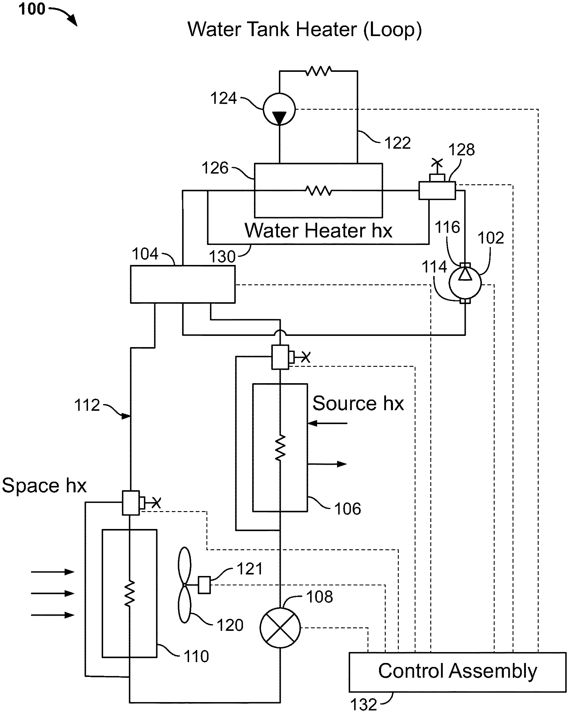
FIG. 1 is a schematic diagram of a heat pump and water heating system constructed in accordance with various embodiments of the instant disclosure.
FIG. 2 is a schematic diagram of the heat pump and water heating circuit of FIG. 1 shown operating in a space cooling mode. The system controls are omitted to simplify the illustration.
FIG. 3 is a schematic diagram of the heat pump and water heating circuit of FIG. 1 shown operating in a space cooling and water heating mode.
FIG. 4 is a schematic diagram of the heat pump and water heating circuit of FIG. 1 shown operating in a space heating mode.
FIG. 5 is a schematic diagram of the heat pump and water heating circuit of FIG. 1 shown operating in a space heating and water heating mode.
FIG. 6 is a schematic diagram of the heat pump and water heating circuit of FIG. 1 shown operating in a water heating mode.
FIG. 7 shows the refrigerant cycles of the system of the present invention graphed onto a P-h (pressure-enthalpy) chart. The cycle designated as "A" illustrates the refrigerant cycle operating without the water heater heat exchanger (WHHX) and the cycle designated as "B" illustrates the refrigerant cycle operating with the water heater heat exchanger.
DETAILED DESCRIPTION OF THE PREFERRED EMBODIMENT(S)
The instant disclosure discloses a heat pump and water heater system having a simplified, reliable, flexible and inexpensive design that provides five distinct modes of operation that can be extended to numerous combinations thereof. In at least one embodiment, this is accomplished in principle by the addition of a water heating heat exchanger and a refrigerant bypass line around the water heating heat exchanger. A three-way valve allows the refrigerant flow through the bypass line to be actuated and controlled. The refrigerant circuit configurations in cooling and heating modes of operation for the conditioned space disclosed herein can integrate water heating with the space conditioning or employ water heating independently from the space conditioning. Furthermore, the system design is not susceptible to the refrigerant charge migration common in conventional systems. The system provides an advantage of requiring a lower refrigerant charge amount (which may be critical for the conversion to the low global warming refrigerants), provides enhanced efficiency in all modes of operation, and allows for an extended operational envelope.
Referring to FIG. 1, the heat pump system 100 comprises a compressor 102, a four-way reversing valve 104, a source heat exchanger 106, an expansion device 108, and a space heat exchanger 110, all interconnected by refrigerant lines designated collectively at 112. The compressor 102 has a suction inlet port 114 and discharge outlet port 116. The compressor 102 compresses refrigerant from a low pressure P.sub.1 to a high pressure P.sub.2 and circulates refrigerant throughout the refrigerant circuit.
The compressor 102 may be a variable capacity compressor, such as a variable speed compressor, a compressor with an integral pulse width modulation option, or a compressor incorporating various unloading options. These types of compressors allow for better control of the operating conditions and manage the thermal load on the heat pump system 100.
The source heat exchanger 106 may be a refrigerant-to-water, refrigerant-to-brine, or refrigerant-to-air heat exchanger and is not limited to any particular heat exchanger type or configuration. The associated fan or pump (not shown) may be of a variable flow type, such as being driven by a variable speed motor, a pulse width-modulated motor, or an ON/OFF cycling motor, to enhance operation and control of the heat pump system 100.
The expansion device 108 may be an electronic expansion valve, a mechanical expansion valve, or a fixed-orifice/capillary tube/accurator. The expansion device 108 may have bi-directional design or may be replaced by a pair of unidirectional expansion devices with the associated check valve bypass options to provide refrigerant re-routing when the flow changes direction throughout the refrigerant cycle.
The space heat exchanger 110 may be a refrigerant-to-air, refrigerant-to-water or refrigerant-to-brine heat exchanger and is not limited to any particular heat exchanger type or configuration. In the case of the exemplary air-to-refrigerant heat exchanger shown in the drawings, the associated air management system may be a fan 120 of any known type and may be equipped with a variable flow capability feature, such as being driven by a variable speed motor 121, to enhance operation and control of the heat pump system 100. Alternately, the motor 121 may be a pulse width modulated motor or an ON/OFF cycling motor. Of course, in the case of a water-to-refrigerant or brine-to-refrigerant heat exchanger, the fan 120 and motor 121 are replaced by a pump and a motor that may incorporate similar variable capacity capability.
The heat pump system 100 includes a water tank heater loop 122 for heating water in the structure (not shown). A pump 124 circulates water through the loop 122 and a water heater heat exchanger (WHHX) 126. The pump 124 may have a variable flow capability, such as being driven by a variable speed motor, pulse width modulated motor, or ON/OFF cycling motor, to better control operating conditions for the heat pump system 100 and water temperature within the water tank (not shown). The water heater heat exchanger 126, which is typically a refrigerant-to-water heat exchanger, is connected in-line between the discharge side of the compressor 102 and the 4-way reversing valve 104. The water heater heat exchanger 126 operates as a desuperheater and a condenser when it is engaged within the active refrigerant circuit of the heat pump system 100.
A 3-way valve 128 interposed between the compressor 102 and water heater heat exchanger 126 allows the system control 132 for the heat pump system 100 to command the operation of the loop 122. A bypass line 130 (WHHX bypass) connects the 3-way valve 128 to the outlet side of the water heater heat exchanger 126 to direct at least a portion of refrigerant around the water heater heat exchanger 126 when the water tank heater loop 122 is not actuated.
In at least one embodiment, the 3-way valve 128 is a modulating type and can be controlled by a stepper motor (not shown) permitting the system control 132 for the heat pump system 100 modulate the percentage of the refrigerant flow directed through the bypass line 130 thus allowing for a better control of operating conditions for the heat pump system 100 and improved operation of the water heater heat exchanger 126.
Alternately, the 3-way valve 128 may be replaced by a pair of conventional valves, such as a pair of rapid cycle solenoid valves, or by a rapid cycle three-way valve. Furthermore, to prevent refrigerant migration while switching between different modes of operation, a check valve (not shown) may be positioned downstream the water heater heat exchanger 126 with respect to the refrigerant flow. Additionally, the 3-way valve 128 may be positioned at the exit of the water heater heat exchanger 126 with respect to the refrigerant flow.
The heat pump system 100 has five distinct modes of operation that are primarily controlled by the 4-way valve 104 and the 3-way valve 128, while augmented by the multiple variable capacity devices, such as compressors, fans and pumps, integrated into the system. These modes of operation are space cooling only, space cooling and water heating, space heating only, space heating and water heating, and water heating only. Additionally, the heat pump system 100 may adjust operation in any of the modes depicted above and exactly match the space conditioning and water heating requirements without excessive ON/OFF cycling that negatively impacts system reliability and fluctuations in operating conditions.
In the space cooling mode of operation depicted in FIG. 2, the refrigerant is compressed in the compressor 102 and discharged from the compressor discharge port 116 into the discharge refrigerant line 112a connecting the compressor 102 to the 3-way valve 128. In the cooling mode of operation, the 3-way valve 128 directs the refrigerant flow through the bypass line 130 around the water heater heat exchanger 126 and refrigerant line 112b connecting the 3-way valve 120 and the 4-way valve 104.
The 4-way valve 104 is configured to connect the refrigerant to the source heat exchanger 106 through the refrigerant line 112c. In this mode, the source heat exchanger 106 is operating as a condenser to desuperheat, condense, and subcool the refrigerant and rejects heat from the refrigerant system to the environment (not shown).
Downstream the source heat exchanger 106, the refrigerant flows through the expansion device 108, where it is expanded from a high pressure to a lower pressure and its temperature is reduced. The refrigerant is then directed to the refrigerant line 112d and the space heat exchanger 110 that is acting as an evaporator and superheater in the cooling mode of operation, while removing heat and reducing humidity in the conditioned space (not shown). Downstream of the space heat exchanger 110, refrigerant line 112e connects the space heat exchanger 110 to the 4-way valve 104, which is configured to direct the refrigerant to the suction port 114 of the compressor 102 through the refrigerant line 112f to complete the refrigerant circuit.
In the space cooling and water heating mode of operation depicted in FIG. 3, the 3-way valve 128 is configured to direct at least a portion of refrigerant through the water heater heat exchanger 126, instead of the bypass refrigerant line 130. In this mode of operation, the water heating heat exchanger 126 may operate as a desuperheater and partial condenser or, alternately, as a desuperheater, condenser, and subcooler. In the former case, the source heat exchanger 106 is used to complete the condensation process and subcool the refrigerant. In the latter case, the source heat exchanger 106 is used to further subcool the refrigerant and improve operational efficiency and dehumidification capability of the heat pump system 100 (see FIG. 7). Alternatively, in the latter case, the source heat exchanger 106 may be bypassed through a bypass line 134 using a 3-way valve 136 (as shown in broken lines) and the water supply for the source heat exchanger 106 may be shut down to reduce input power for the circulating pump (not shown). The 3-way valve 136 may have a variable capability feature and may be utilized as an auxiliary performance control and pressure control device. In all other aspects, this mode of operation is similar to the cooling mode of operation of FIG. 2.
It will be understood that, if the 3-way valve 128 has regulating (modulating) capability, the refrigerant flow between the bypass refrigerant line 130 and the water heating heat exchanger 126 can be adjusted in any proportion from zero to one hundred percent (0%-100%), precisely satisfying the water heating demand typically defined and measured by the temperature transducer integrated into the water tank, reducing a number of ON/OFF cycles, and thus improving system efficiency and reliability. Such flexibility of the 3-way modulating valve 128 may be combined with other variable capacity devices of the heat pump system 100 described above.
In the space heating mode of operation depicted in FIG. 4, the refrigerant is compressed in the compressor 102 and discharged from the compressor discharge port 116 into the discharge refrigerant line 112a connecting the compressor 102 to the 3-way valve 128. In the heating mode of operation, the 3-way valve 128 directs the refrigerant flow through the bypass line 130 around the water heater heat exchanger 126 and refrigerant line 112b connecting the 3-way valve and the 4-way valve 104. The 4-way valve 104 is configured to direct the refrigerant through the refrigerant line 112e to the space heat exchanger 110, which in this mode operates as a condenser to desuperheat, condense, and subcool the refrigerant while heating the conditioned space (not shown). Downstream of the space heat exchanger 110, the refrigerant is directed through the refrigerant line 112d to the expansion device 108 where it is expanded from a high pressure to a lower pressure while its temperature is reduced. The refrigerant is then passed through the source heat exchanger 106 acting as an evaporator and superheater, in the heating mode of operation. Downstream of the source heat exchanger 106, the 4-way valve 104 is configured to direct the refrigerant through the refrigerant line 112f to the suction port 114 of the compressor 102 to complete the refrigerant cycle.
In the space heating and water heating mode of operation depicted in FIG. 5, the 3-way valve 128 is configured to direct at least a portion of refrigerant through the water heater heat exchanger 126, instead of the bypass refrigerant line 130. In this mode of operation, the water heating heat exchanger 126 may operate as a desuperheater and partial condenser or, alternately, as a desuperheater, condenser, and subcooler. In the former case, the space heat exchanger 110 may be used to complete the condensation process and subcool the refrigerant. In the latter case, the space heat exchanger 110 may be used to further subcool the refrigerant to improve operational efficiency of the heat pump system 100 (see FIG. 7). Alternatively, in the latter case, at least a portion of refrigerant flow may bypass the space heat exchanger 110 through bypass line 140 using a 3-way valve 142 (as shown in broken lines in FIG. 6) and the airflow for the source heat exchanger 106 may be adjusted to reduce input power for the for the circulating fan (not shown). The 3-way valve 142 may have a variable capability feature and may be utilized as an auxiliary performance control and pressure control device. In all other aspects, this mode of operation is similar to the heating mode of operation depicted in FIG. 4.
It will be understood that the space heating requirements take the priority over the water heating and that water heating may be supplemented, if required, with a gas or electric heater (not shown). Furthermore, if the 3-way valve 128 has regulating (modulating) capability, the refrigerant flow between the bypass refrigerant line 130 and the water heating heat exchanger 126 can be adjusted in any proportion from zero to one hundred percent (0%-100%) precisely satisfying the water heating demand typically defined and measured by the temperature transducer integrated into the water tank, reducing a number of ON/OFF cycles, and thus improving system efficiency and reliability. Such flexibility of the 3-way modulating valve 128 may be combined with other variable capacity devices of the heat pump system 100 described above.
In the water heating only mode of operation depicted in FIG. 6, the 3-way valve 128 is configured to direct the refrigerant through the water heater heat exchanger 126, instead of the bypass refrigerant line 130. In this mode of operation, the water heating heat exchanger 126 operates as a desuperheater, condenser, and subcooler. In this mode of operation, the airflow or water flow through the space heat exchanger 110 is deactivated. Alternatively, the space heat exchanger 110 may be bypassed through the bypass line 140 using the 3-way valve 142 to reduce the refrigerant side parasitic pressure drop. In all other aspects, this mode of operation is similar to the space heating and water heating mode of operation shown in FIG. 5.
Returning now to FIG. 1, the heat pump system 100 includes the controls 132 operatively connected to the electronic expansion device 108, the fan motor 121 controlling the speed and operation of the fan 120, the 4-way reversing valve 104, the variable speed compressor 102, the three-way valve 128, and the pump motor controlling the speed and operation of the pump 124 in the water heater loop 122. The system controls 132 for the heat pump system 100 will also include various sensors (not shown), such as temperature sensors to report the air temperature in the space, the water temperature of the water in the water tank loop, and temperatures, pressures, flow rates and speed of the various components driven by electric motors, throughout the heat pump system 100.
The control logic will be programmed to selectively operate the water heater heat exchanger loop or/and to at least partially bypass it using the three-way valve 128. The control logic preferably is set up to allow for the space conditioning as the higher priority over water heating. The refrigerant head pressure control, to ensure safe and reliable operation of the system components such as the 4-way reversing valve 104 and compressor 102, can be accomplished by adjusting the compressor speed, fan speed, pump speed, and the amount of refrigerant flowing through the water heater heat exchanger bypass refrigerant lines 130, 134 and 140.
The selective utilization of the water heating heat exchanger 126, in combination with the space heat exchanger 110 or the source heat exchanger 106 and air/water moving devices, such as the fan 120 and the water heater heat exchanger loop pump 124, respectively in the heating and cooling mode of operation, allows for the system performance (capacity and efficiency) optimization and dehumidification capability improvement.
As described above, the heat pump system 100 of the present disclosure offers many advantages and benefits. By way of example, as depicted above and illustrated in the P-h diagram of FIG. 7, when the water heater heat exchanger is included in the active operating circuit of the heat pump system 100, the system efficiency is enhanced, compressor power is reduced, and dehumidification capability is improved. The system provides augmented performance and control as well as offers reduced cost, improved operational flexibility, and enhanced reliability.
The embodiments shown and described above are exemplary. Many details are often found in the art and, therefore, many such details are neither shown nor described herein. It is not claimed that all of the details, parts, elements, or steps described and shown were invented herein. Even though numerous characteristics and advantages of the present disclosure have been described in the drawings and accompanying text, the description is illustrative only. Changes may be made in the details, especially in matters of shape, size, and arrangement of the parts within the principles of the instant disclosure to the full extent indicated by the broad meaning of the terms of the attached claims. The description and drawings of the specific embodiments herein do not point out what an infringement of this patent would be, but rather provide an example of how to use and make the invention as defined by the appended claims. Likewise, the abstract is neither intended to define the invention, which is measured by the appended claims, nor is it intended to be limiting as to the scope of the instant disclosure in any way. Rather, the limits of the invention and the bounds of patent protection are measured by and defined in the following claims.
* * * * *
References
D00000
D00001
D00002
D00003
D00004
D00005
D00006
D00007
XML
uspto.report is an independent third-party trademark research tool that is not affiliated, endorsed, or sponsored by the United States Patent and Trademark Office (USPTO) or any other governmental organization. The information provided by uspto.report is based on publicly available data at the time of writing and is intended for informational purposes only.
While we strive to provide accurate and up-to-date information, we do not guarantee the accuracy, completeness, reliability, or suitability of the information displayed on this site. The use of this site is at your own risk. Any reliance you place on such information is therefore strictly at your own risk.
All official trademark data, including owner information, should be verified by visiting the official USPTO website at www.uspto.gov. This site is not intended to replace professional legal advice and should not be used as a substitute for consulting with a legal professional who is knowledgeable about trademark law.