Refrigerant Vapor Compression System
Taras; Michael F. ; et al.
U.S. patent application number 12/867846 was filed with the patent office on 2010-12-30 for refrigerant vapor compression system. This patent application is currently assigned to Carrier Corporation. Invention is credited to Alexander Lifson, Michael F. Taras.
| Application Number | 20100326100 12/867846 |
| Document ID | / |
| Family ID | 40985810 |
| Filed Date | 2010-12-30 |


| United States Patent Application | 20100326100 |
| Kind Code | A1 |
| Taras; Michael F. ; et al. | December 30, 2010 |
REFRIGERANT VAPOR COMPRESSION SYSTEM
Abstract
A refrigerant vapor compression system includes a first compression device, a refrigerant heat rejection heat exchanger, an expansion device, a refrigerant heat absorption heat exchanger, a second compression device, and a refrigerant-to-refrigerant heat exchanger having first refrigerant flow pass, a second refrigerant flow pass and a third refrigerant flow pass, with the second refrigerant flow pass disposed in heat exchange relationship with each of the first refrigerant flow pass and the third refrigerant flow pass. The second refrigerant flow pass is interdisposed in an economizer circuit. The heat transfer interaction between the first and second refrigerant flow passes functions as a subcooler of refrigerant flowing to the refrigerant heat absorption heat exchanger and the heat transfer interaction between the second and third refrigerant flow passes functions as an intercooler of refrigerant passing from the discharge outlet of the second compression device to the suction inlet of the first compression device.
| Inventors: | Taras; Michael F.; (Fayetteville, NY) ; Lifson; Alexander; (Manlius, NY) |
| Correspondence Address: |
    MARJAMA MULDOON BLASIAK & SULLIVAN LLP
    250 SOUTH CLINTON  STREET, SUITE 300
    SYRACUSE
    NY
    13202
    US
|
| Assignee: | Carrier Corporation Farmington CT |
| Family ID: | 40985810 |
| Appl. No.: | 12/867846 |
| Filed: | February 19, 2008 |
| PCT Filed: | February 19, 2008 |
| PCT NO: | PCT/US08/54268 |
| 371 Date: | August 16, 2010 |
| Current U.S. Class: | 62/115 ; 62/510; 62/513 |
| Current CPC Class: | F25B 2400/072 20130101; F25B 1/10 20130101; F25B 2400/13 20130101; F25B 2400/075 20130101 |
| Class at Publication: | 62/115 ; 62/510; 62/513 |
| International Class: | F25B 1/00 20060101 F25B001/00; F25B 1/10 20060101 F25B001/10; F25B 41/00 20060101 F25B041/00 |
Claims
1. A refrigerant vapor compression system comprising: a first compression device, a refrigerant heat rejection heat exchanger, a primary expansion device, a refrigerant heat absorption heat exchanger, and a second compression device connected in serial refrigerant flow communication in a primary refrigerant circuit with a refrigerant discharge outlet of said second compression device in refrigerant flow communication with a suction inlet of said first compression device; and a common heat exchanger providing an economizer function for cooling refrigerant passing through the primary refrigerant circuit from said refrigerant heat rejection heat exchanger to said primary expansion device and an intercooler function for cooling refrigerant passing through said primary refrigerant circuit from the refrigerant discharge outlet of said second compression device to the refrigerant suction inlet of said first compression device.
2. A refrigerant vapor compression system comprising: a first compression device, a refrigerant heat rejection heat exchanger, a primary expansion device, a refrigerant heat absorption heat exchanger, and a second compression device connected in serial refrigerant flow communication in a primary refrigerant circuit, each of said first and second compression devices having a refrigerant discharge outlet and a refrigerant suction inlet; a refrigerant-to-refrigerant heat exchanger having a first refrigerant flow pass, a second refrigerant flow pass and a third refrigerant flow pass, said first refrigerant flow pass interdisposed in the primary refrigerant circuit between a refrigerant outlet of said refrigerant heat rejection heat exchanger and a refrigerant inlet to said refrigerant heat absorption heat exchanger, said third refrigerant flow pass interdisposed in the primary refrigerant circuit between the refrigerant discharge outlet of said second compression device and the refrigerant suction inlet of said first compression device, said second refrigerant flow pass disposed in heat exchange relationship with at least said first refrigerant flow pass and said third refrigerant flow pass; an economizer refrigerant circuit including an economizer refrigerant line having an inlet in refrigerant flow communication with the primary refrigerant circuit at a location downstream of the refrigerant outlet of said refrigerant heat rejection heat exchanger and upstream of the refrigerant inlet to said refrigerant heat absorption heat exchanger, said second refrigerant flow pass interdisposed in said economizer refrigerant circuit.
3. A refrigerant vapor compression system as recited in claim 2 wherein the economizer refrigerant line of said economizer circuit is in refrigerant flow communication with an intermediate pressure stage of said second compression device.
4. A refrigerant vapor compression system as recited in claim 3 wherein said second compression device comprises a single, multi-stage compressor and the economizer refrigerant line of said economizer refrigerant circuit is in refrigerant flow communication with an intermediate pressure stage of the multi-stage compressor.
5. A refrigerant vapor compression system as recited in claim 2 wherein the economizer refrigerant line of said economizer circuit is in refrigerant flow communication with an intermediate pressure stage of said first compression device.
6. A refrigerant vapor compression system as recited in claim 5 wherein said first compression device comprises a single, multi-stage compressor and the economizer refrigerant line of said economizer refrigerant circuit is in refrigerant flow communication with an intermediate pressure stage of the multi-stage compressor.
7. A refrigerant vapor compression system as recited in claim 2 wherein said second compression device comprises a multi-stage compressor having a first compression stage and a second compression stage disposed in series refrigerant flow relationship, with a refrigerant discharge of said first compression stage in refrigerant flow communication with a refrigerant inlet of said second compression stage, said second pass of said refrigerant-to-refrigerant heat exchanger in refrigerant flow communication with the refrigerant inlet of said second compression stage, and said third pass of said refrigerant-to-refrigerant heat exchanger in refrigerant flow communication with the refrigerant inlet of said first compression device.
8. A refrigerant vapor compression system as recited in claim 2 wherein said first compression device comprises a multi-stage compressor having a first compression stage and a second compression stage disposed in series refrigerant flow relationship, with a refrigerant discharge of said first compression stage in refrigerant flow communication with a refrigerant inlet of said second compression stage, said second pass of said refrigerant-to-refrigerant heat exchanger in refrigerant flow communication with the refrigerant inlet of said second compression stage, and said third pass of said refrigerant-to-refrigerant heat exchanger in refrigerant flow communication with the refrigerant inlet of said first compression stage.
9. A refrigerant vapor compression system as recited in claim 2 further comprising a third compression device having a refrigerant outlet in refrigerant flow communication with a refrigerant inlet to said refrigerant heat rejection heat exchanger and a refrigerant inlet, the second pass of said refrigerant-to-refrigerant heat exchanger in refrigerant flow communication with the refrigerant inlet of said third compression device.
10. A refrigerant vapor compression system as recited in claim 2 further comprising a pre-cooler heat exchanger interdisposed in the primary refrigerant circuit downstream, with respect to refrigerant flow, of the refrigerant outlet of said second compression device and upstream, with respect to refrigerant flow, of said third pass of said refrigerant-to-refrigerant heat exchanger.
11. A refrigerant vapor compression system as recited in claim 10 wherein said pre-cooler heat exchanger is disposed in heat transfer relationship with a secondary fluid being passed in heat transfer relationship with the refrigerant passing through said refrigerant heat rejection heat exchanger.
12. A refrigerant vapor compression system as recited in claim 11 wherein the secondary fluid is ambient air.
13. A refrigerant vapor compression system as recited in claim 10 wherein said pre-cooler heat exchanger shares the same housing structure with the heat rejection heat exchanger.
14. A refrigerant vapor compression system as recited in claim 10 wherein said pre-cooler heat exchanger shares the same heat exchanger core with the heat rejection heat exchanger.
15. A method of operating a refrigerant vapor compression system having a first compression device, a refrigerant heat rejection heat exchanger, a primary expansion device, a refrigerant heat absorption heat exchanger, and a second compression device connected in serial refrigerant flow communication in a primary refrigerant circuit with a refrigerant discharge outlet of said second compression device in refrigerant flow communication with a suction inlet of said first compression device; said method comprising the steps of: passing a first portion of the refrigerant leaving the refrigerant heat rejection heat exchanger through the primary refrigerant circuit to the refrigerant heat absorption heat exchanger; expanding a second portion of the refrigerant downstream of the refrigerant heat rejection heat exchanger to an intermediate pressure; passing said second portion of the refrigerant in heat exchange relationship with said first portion of the refrigerant at a location in the primary refrigerant circuit upstream, with respect to refrigerant flow, of the primary expansion device; and passing said second portion of the refrigerant in heat exchange relationship with the refrigerant flowing through the primary refrigerant circuit from the refrigerant discharge outlet of the second compression device to the refrigerant suction inlet of the first compression device.
16. A method as recited in claim 15 further comprising passing said second portion of the refrigerant in counterflow heat exchange relationship both with said first portion of the refrigerant and with the refrigerant flowing through the primary refrigerant circuit from the second compression device to the first compression device.
17. A method as recited in claim 15 further comprising the step of pre-cooling the refrigerant flowing through the primary refrigerant circuit from the second compression device to the first compression device prior to passing said second portion of the refrigerant in heat exchange relationship with the refrigerant flowing through the primary refrigerant circuit from the second compression device to the first compression device.
Description
FIELD OF THE INVENTION
[0001] This invention relates generally to refrigerant vapor compression systems and, more particularly, to enhancing the performance of a refrigerant vapor compression system.
BACKGROUND OF THE INVENTION
[0002] Refrigerant vapor compression systems are commonly used in transport refrigeration applications for refrigerating the atmosphere within a temperature-controlled cargo space of a truck, trailer, container or the like for transporting perishable or frozen items. Refrigerant vapor compression systems are also commonly used in refrigerating air supplied to display cases, merchandisers, freezer cabinets, cold rooms or other perishable/frozen product storage area in commercial establishments and for conditioning air to be supplied to a climate-controlled comfort zone within a residence, office building, hospital, school, restaurant or other facility.
[0003] Typically, these refrigerant vapor compression systems include a compression device, a refrigerant heat rejection heat exchanger, an expansion device and a refrigerant heat absorption heat exchanger, serially interconnected by various refrigerant lines in refrigerant flow communication in a closed-loop refrigerant circuit, arranged in accord with known refrigerant vapor compression cycles. Commonly, the expansion device, which is disposed in the refrigerant circuit upstream, with respect to refrigerant flow, of the refrigerant heat absorption heat exchanger and downstream, with respect to refrigerant flow, of the refrigerant heat rejection heat exchanger, is a fixed orifice, a capillary tube, a thermostatic expansion valve (TXV) or an electronic expansion valve (EXV).
[0004] In refrigerant vapor compression systems operating in a subcritical cycle, the refrigerant heat rejection heat exchanger functions as a refrigerant vapor condenser. Refrigerant vapor compression systems operating in the subcritical range are commonly charged with fluorocarbon refrigerants such as, but not limited to, hydrochlorofluorocarbons (HCFCs), such as R22, and more commonly hydrofluorocarbons (HFCs), such as R134a, R410A, R404A and R407C. However, greater interest is being shown in "natural" refrigerants, such as carbon dioxide, for use in air conditioning and refrigeration systems, including transport refrigeration systems, instead of HFC refrigerants. However, because carbon dioxide has a low critical temperature, most refrigerant vapor compression systems charged with carbon dioxide as the refrigerant are designed for operation in the transcritical cycle, at least for portion of the time.
[0005] In refrigerant vapor compression systems operating in a transcritical cycle, the pressure and temperature of the refrigerant vapor discharged from the compression device and passing through the refrigerant heat rejection heat exchanger are at supercritical pressure and temperature, that is a pressure and temperature of the refrigerant are above the critical point of the specific refrigerant with which the system is charged. Therefore, the refrigerant heat rejection heat exchanger functions as a refrigerant gas cooler, rather than as a condenser. Having traversed the refrigerant heat rejection heat exchanger, the supercritical pressure refrigerant vapor is expanded to a lower subcritical pressure and lower temperature as the refrigerant vapor traverses the expansion device. Therefore, the refrigerant enters the refrigerant heat absorption heat exchanger as a liquid refrigerant, or more typically, as a mixture of liquid and vapor refrigerant, and the refrigerant heat absorption heat exchanger functions as an evaporator operating at a subcritical refrigerant pressure.
[0006] To improve performance of the refrigerant vapor compression system and to control the temperature of the refrigerant vapor discharged from the final stage of the compressor over a wide range of operating conditions, it is known to equip such systems with an economizer cycle incorporating a refrigerant-to-refrigerant economizer heat exchanger. The economizer heat exchanger is generally disposed in the refrigerant circuit intermediate the heat rejection heat exchanger and the heat absorption heat exchanger, with respect to refrigerant flow. In the economized mode of operation, at least a portion of the refrigerant leaving the heat rejection heat exchanger is diverted from the primary refrigerant circuit, expanded to an intermediate pressure and then passed through the economizer heat exchanger in heat exchange relationship with the main portion of the refrigerant leaving the heat rejection heat exchanger. In this manner, any liquid in the economized expanded refrigerant flow is typically evaporated, and then the economized refrigerant flow is typically superheated, while the refrigerant passing through the primary refrigerant circuit from the heat rejection heat exchanger to the heat absorption heat exchanger is further cooled. Typically, the expanded refrigerant vapor is injected into an intermediate stage in the compression process, either through an injection port or ports opening into an intermediate pressure stage of the compression chamber (or chambers) of a single compressor or, in the case of a multi-stage compressor system, into a refrigerant line extending between the discharge outlet of the upstream compressor and the suction inlet of the downstream compressor.
[0007] U.S. Pat. No. 7,114,349 discloses a refrigerant vapor compression system with a refrigerant-to-refrigerant heat exchanger having a first refrigerant pass, a second refrigerant pass and a third refrigerant pass. The first pass is interdisposed in the primary refrigerant circuit downstream of the condenser, with respect to refrigerant flow, and upstream of the evaporator, with respect to refrigerant flow. The second pass is interdisposed in an economizer circuit refrigerant line downstream, with respect to refrigerant flow, of an economizer expansion device. The third refrigerant pass is interdisposed in the primary refrigerant circuit downstream, with respect to refrigerant flow, of the evaporator and upstream, with respect to refrigerant flow, of the suction inlet to the compressor. The first refrigerant pass is disposed in heat transfer relationship with each of the second refrigerant pass and the third refrigerant pass. The heat transfer interaction between the first refrigerant pass and the third refrigerant pass functions as a high side-to-low side heat exchanger wherein the high pressure, high temperature refrigerant passing through the first refrigerant pass is cooled and the low pressure, lower temperature refrigerant vapor passing through the third refrigerant pass is heated. Additionally, when the refrigerant system is operating in an economized mode, the heat transfer interaction between the first refrigerant pass and the second refrigerant pass functions as an economizer heat exchanger wherein the high pressure, high temperature refrigerant passing through the first refrigerant pass is again cooled and the lower pressure, lower temperature expanded refrigerant vapor or vapor/liquid mixture passing through the second refrigerant pass is heated. After traversing the second refrigerant pass of the refrigerant-to-refrigerant heat exchanger, the expanded refrigerant is injected into an intermediate pressure stage of the compressor or returned to the primary refrigerant circuit at a point downstream, with respect to refrigerant flow, of the evaporator and upstream, with respect to refrigerant flow, of the suction inlet of the compressor.
SUMMARY OF THE INVENTION
[0008] A refrigerant vapor compression system includes a primary refrigerant circuit having a first compression device, a refrigerant heat rejection heat exchanger, an expansion device, a refrigerant heat absorption heat exchanger, and a second compression device connected in serial refrigerant flow communication, with the refrigerant discharge outlet of the second compression device being connected in refrigerant flow communication with the refrigerant inlet of the first compression device, and a common heat exchanger providing an economizer function and an intercooler function. The economizer function serves to cool refrigerant passing through the primary refrigerant circuit from the refrigerant heat rejection heat exchanger to the primary expansion device. The intercooler function serves to cool refrigerant passing through the primary refrigerant circuit from the refrigerant discharge outlet of the second compression device to the refrigerant suction inlet of the first compression device
[0009] In an embodiment, the refrigerant vapor compression system includes a primary refrigerant circuit having a first compression device, a refrigerant heat rejection heat exchanger, an expansion device, a refrigerant heat absorption heat exchanger, and a second compression device connected in serial refrigerant flow communication, with the refrigerant discharge outlet of the second compression device being connected in refrigerant flow communication with the refrigerant inlet of the first compression device, and further includes a refrigerant-to-refrigerant heat exchanger and an economizer circuit. The refrigerant-to-refrigerant heat exchanger has a first refrigerant flow pass, a second refrigerant flow pass and a third refrigerant flow pass, with the second refrigerant flow pass disposed in heat exchange relationship with each of the first refrigerant flow pass and the third refrigerant flow pass. The first refrigerant flow pass is interdisposed in the primary refrigerant circuit downstream, with respect to refrigerant flow, of the refrigerant heat rejection heat exchanger and upstream, with respect to refrigerant flow, of the expansion device. The third refrigerant flow pass is interdisposed in the primary refrigerant circuit between the refrigerant discharge of the second compression device and the refrigerant inlet of the first compression device, both with respect to refrigerant flow. The economizer circuit includes an economizer refrigerant line having an inlet in refrigerant flow communication with the primary refrigerant circuit at a location downstream of the refrigerant outlet of the refrigerant heat rejection heat exchanger, with respect to refrigerant flow, and upstream of the refrigerant inlet to the refrigerant heat absorption heat exchanger, also with respect to refrigerant flow. The second refrigerant flow pass is interdisposed in the economizer refrigerant line. An economizer expansion device is disposed in the refrigerant line upstream, with respect to refrigerant flow of the second refrigerant flow pass.
[0010] In an embodiment, the second compression device comprises a single, multi-stage compressor and the outlet of the economizer refrigerant line is in refrigerant flow communication with an intermediate pressure stage of this second multi-stage compression device. In an embodiment, the second compression device comprises a first compressor and a second compressor disposed in serial refrigerant flow relationship, with the refrigerant discharge of the second compressor being in refrigerant flow communication with the refrigerant suction of the first compressor, and the economizer refrigerant line is in refrigerant flow communication with the refrigerant inlet of the second compressor of the second compression device. In another embodiment, the refrigerant vapor compression system further includes a third compression device disposed in parallel refrigerant flow relationship with the first compression device, with the discharge outlet of the third compression device being in refrigerant flow communication with the refrigerant inlet of the refrigerant heat rejection heat exchanger and the economizer refrigerant line in refrigerant flow communication with the refrigerant inlet of the third compression device.
[0011] In a further embodiment, the refrigerant vapor compression system includes a pre-cooler heat exchanger interdisposed in the primary refrigerant circuit downstream, with respect to refrigerant flow, of the refrigerant outlet of the second compression device and upstream, with respect to refrigerant flow, of the third refrigerant flow pass of the refrigerant-to-refrigerant heat exchanger. The pre-cooler heat exchanger may be disposed in heat transfer relationship with a secondary fluid, such as, for example, ambient air, being passed in heat transfer relationship with the refrigerant passing through the refrigerant heat rejection heat exchanger.
[0012] In an aspect of the invention, a method of operating a refrigerant vapor compression system having a first compression device, a refrigerant heat rejection heat exchanger, a primary expansion device, a refrigerant heat absorption heat exchanger, and a second compression device connected in serial refrigerant flow communication in a primary refrigerant circuit with a refrigerant discharge outlet of said second compression device in refrigerant flow communication with a suction inlet of said first compression device is provided. The method includes the steps of: passing a first portion of the refrigerant leaving the refrigerant heat rejection heat exchanger through the primary expansion device of the primary refrigerant circuit to the refrigerant heat absorption heat exchanger; expanding a second portion of the refrigerant in an economizer expansion device downstream of the refrigerant heat rejection heat exchanger to an intermediate pressure and temperature; passing the second portion of the refrigerant in heat exchange relationship with said first portion of the refrigerant at a location upstream, with respect to refrigerant flow, of the primary expansion device; and passing the second portion of the refrigerant in heat exchange relationship with the refrigerant flowing through the primary refrigerant circuit from the refrigerant discharge outlet of the second compression device to the refrigerant suction inlet of the first compression device.
[0013] In an embodiment, the method includes passing the second portion of the refrigerant in counterflow heat exchange relationship both with the first portion of the refrigerant and with the refrigerant flowing through the primary refrigerant circuit from the second compression device to the first compression device. In an embodiment, the method further includes the step of pre-cooling the refrigerant flowing through the primary refrigerant circuit from the second compression device to the first compression device prior to passing the second portion of the refrigerant in heat exchange relationship with the refrigerant flowing through the primary refrigerant circuit from the second compression device to the first compression device.
BRIEF DESCRIPTION OF THE DRAWINGS
[0014] For a further understanding of the invention, reference will be made to the flowing detailed description of the invention which is to be read in connection with the accompanying drawing, wherein:
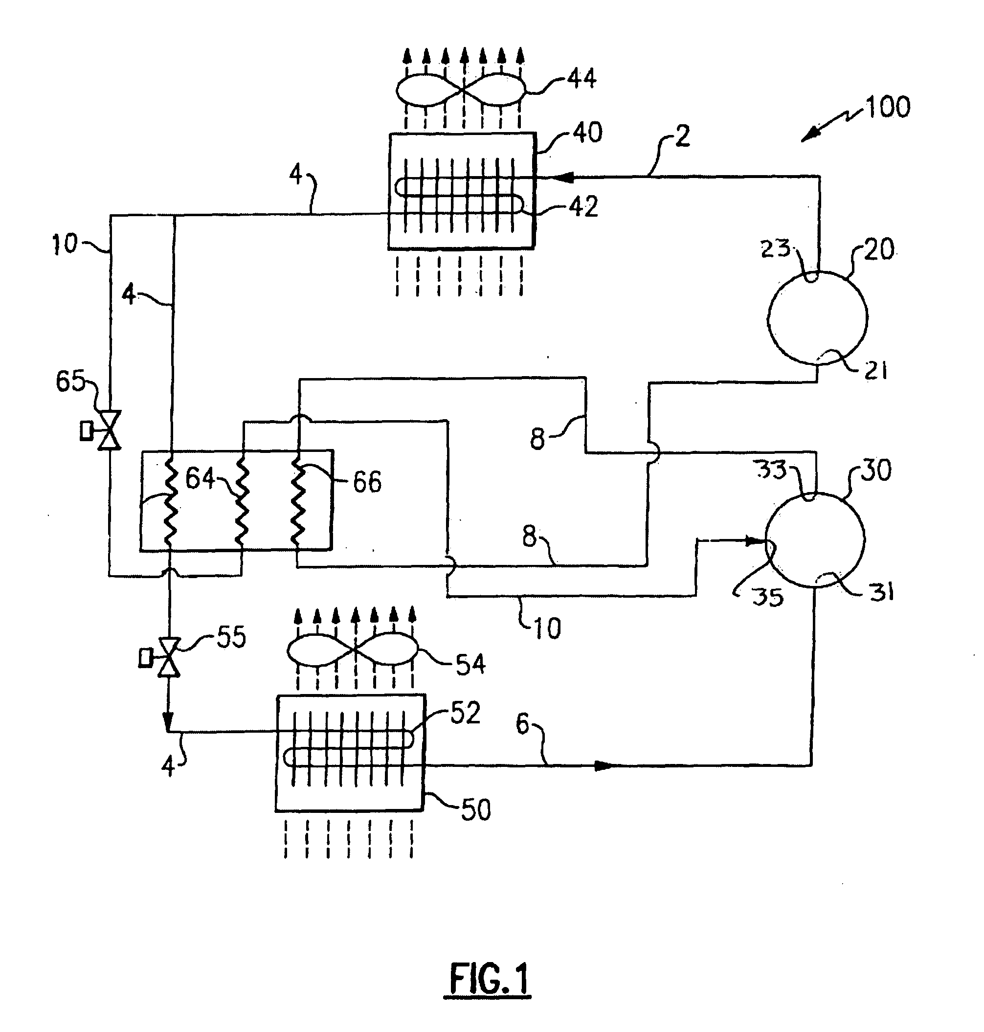
[0015] FIG. 1 is a schematic diagram illustrating a first exemplary embodiment of a vapor compression system in accord with the invention;
[0016] FIG. 2 is a schematic diagram illustrating a second exemplary embodiment of a vapor compression system in accord with the invention;
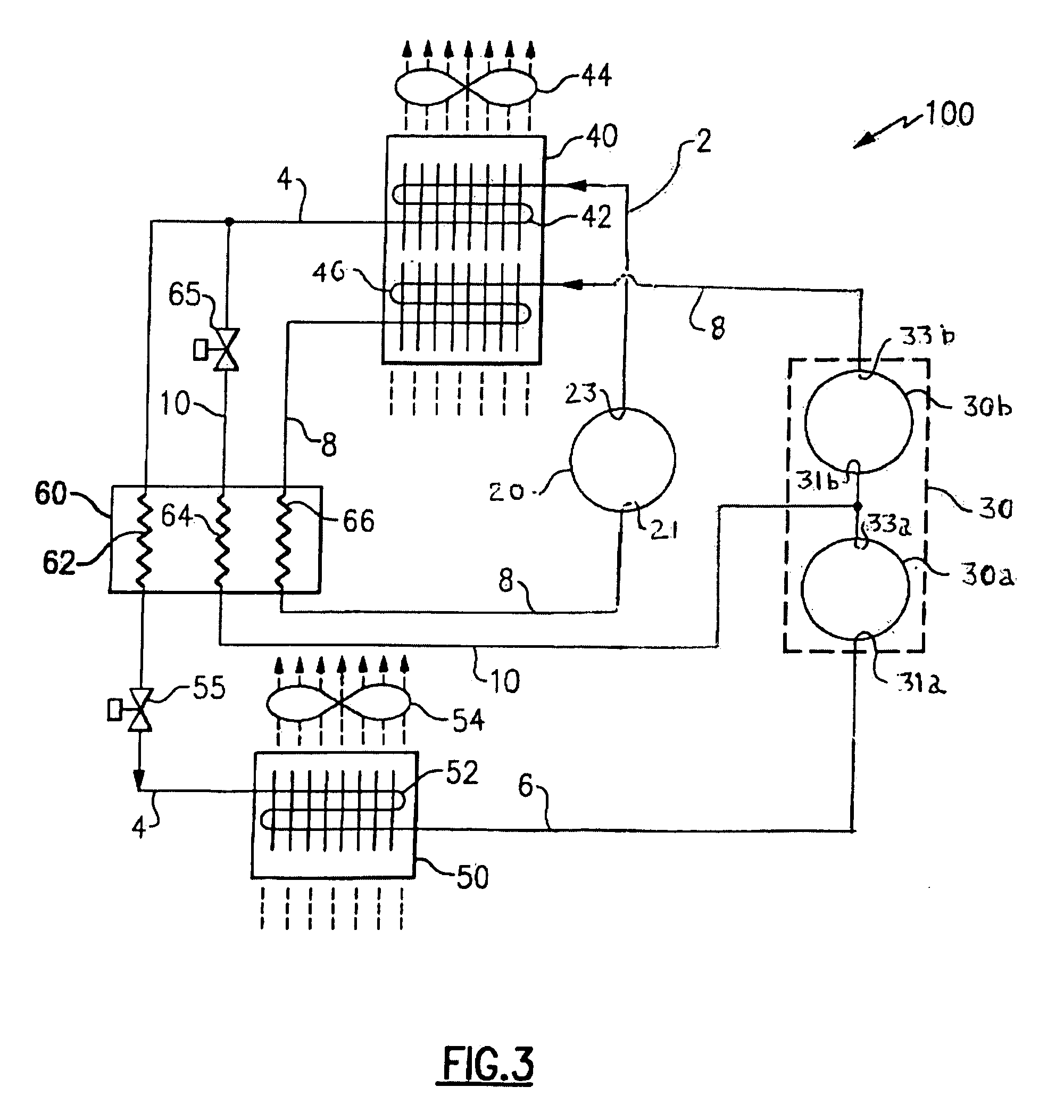
[0017] FIG. 3 is a schematic diagram illustrating a third exemplary embodiment of a vapor compression system in accord with the invention; and
[0018] FIG. 4 is a schematic diagram illustrating a fourth exemplary embodiment of a vapor compression system in accord with the invention.
DETAILED DESCRIPTION OF THE INVENTION
[0019] Referring now to FIGS. 1-4, there are depicted therein several exemplary embodiments of a refrigerant vapor compression system 100 suitable for use in a transport refrigeration applications for refrigerating air supplied to a temperature-controlled cargo space of a truck, trailer, container or the like for transporting perishable and frozen goods; in commercial refrigeration applications for refrigerating air supplied to display cases, merchandisers, freezer cabinets, cold rooms or other perishable and frozen product storage areas in commercial establishments; and in air conditioning applications for residences, office buildings, hospitals, schools, restaurants and other facilities.
[0020] The refrigerant vapor compression system 100 includes a first compression device 20, a refrigerant heat rejection heat exchanger 40, a refrigerant heat absorption heat exchanger 50, and a second compression device 30 connected in serial refrigerant flow communication in a primary refrigerant circuit via refrigerant lines 2, 4, 6 and 8. Each of the first and second compression devices 20, 30 has a refrigerant discharge outlet and a refrigerant suction inlet. The refrigerant line 2 connects the discharge outlet 23 of the first compression device 20 in fluid communication with the inlet to the tube bank 42 of the heat rejection heat exchanger 40. The refrigerant line 4 connects the outlet of the tube bank 42 of the heat rejection heat exchanger 40 in fluid communication with the inlet to the tube bank 52 of the refrigerant heat absorption heat exchanger 50. The refrigerant line 6 connects the outlet of the tank tube 52 of the heat absorption heat exchanger 50 in fluid communication with the refrigerant suction inlet 31 of the second compression device 30. The refrigerant line 8 connects the discharge outlet 33 of the second compression device 30 in fluid communication with the suction inlet 21 of the first compression device 20 to complete the primary refrigerant circuit.
[0021] When the refrigerant vapor compression system 100 is operated in a transcritical vapor compression cycle, the refrigerant vapor discharging from the first compression device 20 through the discharge outlet 23 thereof into the refrigerant line 2 is at a supercritical pressure and temperature. Therefore, the refrigerant heat rejection heat exchanger 40 functions as a gas cooler. The tube bank 42 of the heat rejection heat exchanger 40 may comprise, for example, a finned round tube heat exchanger tube bank, such as for example in a plate fin and round tube heat exchanger, or a corrugated fin and multi-channel flattened tube heat exchanger tube bank, such as for example in a minichannel or microchannel heat exchanger. In traversing the heat rejection heat exchanger 40, the refrigerant passes through the heat exchange tubes of the tube bank 42 in heat exchange relationship with a secondary fluid, typically ambient air, generally outdoor air, being drawn through the tube bank 42 by an air mover 44, such as one or more fans, operatively associated with the tube bank 42 of the heat rejection heat exchanger 40. An expansion valve 55, operatively associated with the heat absorption heat exchanger 50, which functions as an evaporator, is interdisposed in the refrigerant line 4 upstream, with respect to refrigerant flow, of the heat absorption heat exchanger 50 and downstream, with respect to refrigerant flow, of the heat rejection heat exchanger 40.
[0022] The refrigerant leaves the heat rejection heat exchange 40 at a supercritical pressure and lower temperature and passes through the refrigerant line 4 that connects in fluid communication with the inlet to the heat absorption heat exchanger 50. In doing so, the refrigerant traverses through the expansion device 55 interdisposed in the refrigerant line 4 intermediate the heat rejection heat exchanger 40 and the heat absorption heat exchanger 50. The expansion device 55 may be a restriction type expansion device, such as a capillary tube or a fixed plate orifice, a thermostatic expansion valve or an electronic expansion valve. In traversing the expansion device 55, the high pressure refrigerant is expanded to a lower temperature and lower pressure to form a subcritical refrigerant liquid or, more commonly, a subcritical liquid/vapor refrigerant mixture.
[0023] In traversing the heat absorption heat exchanger 50, the refrigerant passes through the heat exchange tubes of the tube bank 52 in heat exchange relationship with air to be conditioned, typically air, at least partially, drawn from and to be returned to a climate-controlled environment, being drawn through the tube bank 52 by an air mover 54, such as one or more fans, operatively associated with the tube bank 52 of the heat absorption heat exchanger 50, whereby the air is cooled, and typically dehumidified, while the refrigerant is evaporated and typically superheated. The tube bank 52 of the heat absorption heat exchanger 50 may comprise, for example, a finned round tube heat exchanger tube bank, such as for example in a plate fin and round tube heat exchanger, or a corrugated fin and multi-channel flattened tube heat exchanger tube bank, such as for example in a minichannel or microchannel heat exchanger. The subcritical pressure refrigerant vapor leaving the heat absorption heat exchanger 50 passes through the refrigerant line 6 to the refrigerant inlet 31 of the second compression device 30.
[0024] The refrigerant vapor compression system 100 further includes a refrigerant-to-refrigerant heat exchanger 60 that functions as both an economizer heat exchanger and a refrigerant intercooler. The refrigerant-to-refrigerant heat exchanger 60 includes a first refrigerant flow pass 62, a second refrigerant flow pass 64 and a third refrigerant flow pass 66. The first refrigerant flow pass 62 is interdisposed in the refrigerant line 4 of the primary refrigerant circuit downstream, with respect to refrigerant flow, of the refrigerant outlet of the refrigerant heat rejection heat exchanger 40 and upstream, with respect to refrigerant flow, of the expansion device 55 disposed upstream, with respect to refrigerant flow, of the refrigerant inlet to the refrigerant heat absorption heat exchanger 50. The third refrigerant flow pass 66 is interdisposed in the refrigerant line 8 of the primary refrigerant circuit between the refrigerant discharge outlet 33 of the second compression device 30 and the refrigerant suction inlet 21 of the first compression device 20.
[0025] The second refrigerant flow pass 64 is interdisposed in an economizer refrigerant line 10 of the economizer refrigerant circuit of the refrigerant vapor compression system 100. The economizer refrigerant line 10 establishes refrigerant flow communication between the refrigerant line 4 of the primary refrigerant circuit and an intermediate pressure stage of the compression process. An economizer circuit expansion device 65 is disposed in the refrigerant line 10 upstream, with respect to refrigerant flow therethrough, of the second pass 64 of the refrigerant-to-refrigerant heat exchanger 60. The economizer refrigerant line 10 may tap a portion of refrigerant from the refrigerant line 4 at a location upstream, with respect to refrigerant flow, of the first refrigerant flow pass 62 of the refrigerant-to-refrigerant heat exchanger 60, as depicted in FIG. 1, or at a location downstream, with respect to refrigerant flow, of the first refrigerant flow pass 62 of the refrigerant-to-refrigerant heat exchanger 60 and upstream, also with respect to refrigerant flow, of the primary expansion valve 55, as depicted in FIG. 2. The economizer refrigerant line 10 delivers refrigerant passing therethrough to an intermediate pressure stage of the compression process, that is, to a location in the compression process having a pressure above the suction inlet pressure at the second compressor 30 and below the discharge pressure at the discharge outlet of the first compressor 20. In the embodiments depicted in FIGS. 1 and 2, the outlet of the economizer refrigerant line 10 opens in fluid flow communication with an intermediate pressure port 35 of the second compressor 30, whereby the economizer refrigerant flow will be injected back into the compression process upstream, with respect to refrigerant flow, of the intercooler circuit 8. However, it is to be understood that the economizer refrigerant line 10 could, if desired, instead be arranged to open in fluid flow communication with an intermediate pressure port of the first compressor 20, whereby the economizer refrigerant flow would be injected back into the compression process downstream of the intercooler circuit 8.
[0026] The high pressure, high temperature refrigerant tapped from the refrigerant line 4 of the primary refrigerant circuit traverses the economizer expansion device 65 as it passes through the economizer refrigerant line 10 prior to traversing the second pass 64 of the refrigerant-to-refrigerant heat exchanger 60. In traversing the economizer expansion device 65, the high pressure, high temperature refrigerant is expanded to an intermediate pressure and temperature, that is a pressure and temperature lower than the refrigerant discharge temperature and pressure, respectively, but higher than the refrigerant suction pressure and temperature, respectively. The second refrigerant flow pass 64 is disposed in heat exchange relationship with each of the first refrigerant flow pass 62 and the third refrigerant flow pass 66. When the refrigerant vapor compression system 100 is operated in a transcritical vapor compression cycle, the refrigerant tapped from the refrigerant line 4 is a single-phase refrigerant at a supercritical pressure and the expanded refrigerant flowing through the economizer refrigerant line 10 downstream of the economizer expansion device 65 is typically a refrigerant liquid/vapor mixture at a subcritical pressure. The economizer expansion device 65 may be a restriction type expansion device, such as a capillary tube or a fixed plate orifice, a thermostatic expansion valve operatively associated with a temperature sensing bulb, or an electronic expansion valve.
[0027] As mentioned above, the second refrigerant flow pass 64 is disposed in heat exchange relationship with each of the first refrigerant flow pass 62 and the third refrigerant flow pass 66. When the refrigerant vapor compression system 100 is operated in a subcritical vapor compression cycle, the refrigerant tapped from the refrigerant line 4 is a liquid at a subcritical pressure and the expanded refrigerant flowing through the economizer refrigerant line 10 downstream of the economizer expansion device 65 is typically a refrigerant liquid/vapor mixture at a lower subcritical pressure. Thus, refrigerant flowing through the second refrigerant flow pass 64 will always be a cooling medium with respect to the refrigerant passing through the first refrigerant flow pass 62 and also with respect to the refrigerant passing through the third refrigerant flow pass 66. It should be noted that the second refrigerant pass 64 may be arranged so as to pass refrigerant through the refrigerant-to-refrigerant heat exchanger in a direction opposite to, i.e. in counterflow to, the flow of refrigerant through the first and third refrigerant passes 62 and 66, as depicted in FIGS. 1 and 2, or in the same direction as, i.e. in parallel flow to, the flow of refrigerant through the first and third refrigerant passes 62 and 66, as depicted in FIGS. 3 and 4. However, it is to be understood that it is more desirable, from a heat transfer effectiveness perspective, to have the second refrigerant flow pass 64 arranged in a counterflow configuration with respect to the first and third refrigerant flow passes 62 and 66.
[0028] Therefore, when the system 100 is operating in an economized mode, the refrigerant-to-refrigerant heat exchanger 60 functions as both a refrigerant intercooler and an economizer heat exchanger. The intercooler function is provided by the heat transfer interaction between the second refrigerant flow pass 64 and the third refrigerant flow pass 66 as the expanded refrigerant passing through the second refrigerant flow pass 64 cools the refrigerant passing through the third refrigerant flow pass 66 from the discharge outlet of the second compression device 30 to the suction inlet of the first compression device 20 via the refrigerant line 8. The economizer function is provided by the heat transfer interaction between the second refrigerant flow pass 64 and the first refrigerant flow pass 62 as the expanded refrigerant passing through the second refrigerant flow pass 64 cools the refrigerant passing through the first refrigerant flow pass 62 from the refrigerant heat rejection heat exchanger 40 to the refrigerant heat absorption line heat exchanger 50 via the refrigerant line 4.
[0029] In the exemplary embodiments of the refrigerant vapor compression system 100 depicted in FIGS. 1 and 2, the first compression device 20 and the second compression device 30 comprise separate compressors connected in series refrigerant flow relationship with the refrigerant discharge outlet 33 of the second compressor 30 connected in refrigerant flow communication with the refrigerant suction inlet 21 of the first compressor 20, with the first compressor 20 operating at a higher pressure than the pressure at which the second compressor 30 operates. As depicted in FIGS. 1 and 2, in these embodiments, the economizer refrigerant line 10 opens in refrigerant flow communication to an intermediate pressure stage of the second, i.e. lower pressure, compressor 30, although, as mentioned above, the economizer refrigerant line 10 can be configured to open in refrigerant flow communication to an intermediate pressure stage of the first, i.e. higher pressure, compressor 20, if desired and feasible. In these embodiments each of the compressors 20 and 30 generally comprises a single stage refrigerant compressor, such as, for example, a scroll compressor, a rotary compressor, a screw compressor, a reciprocating compressor, a centrifugal compressor or the like.
[0030] In the exemplary embodiment of the refrigerant vapor compression system 100 depicted in FIG. 2, refrigerant leaving the discharge outlet 33 of the second compressor 30 transverses a heat exchange tube bank 46 in heat exchange relationship with ambient air, prior to entering the third refrigerant flow pass 66 of the refrigerant-to-refrigerant heat exchanger 60, and then returning to the suction inlet 21 of the first compressor 20. Such arrangement provides pre-cooling of the refrigerant exiting the discharge outlet 33 of the compressor 30 by ambient air, prior to entering the third refrigerant flow pass 66 of the refrigerant-to-refrigerant heat exchanger 60, where it is further cooled by the economized refrigerant flow transverse the second refrigerant flow pass 64. It has to be understood that the pre-cooling heat exchange tube bank 46 can be arranged in sequential configuration or in parallel configuration, with respect to ambient airflow, in relation to the heat rejection heat exchanger tube bank 42. Further, the pre-cooler tube bank 46 can share the same heat exchanger core and/or housing structure with the heat rejection heat exchanger tube bank 42 or can be configured as a separate stand-alone heat exchanger, as well as can utilize the same air moving device 44, as shown in the FIGS. 2-4, or can be associated with a separate dedicated air moving device. As the heat rejection heat exchanger tube bank 42, the heat exchange tube bank 46 may be, for instance, of a round tube and plate fin type or a corrugated fin and flattened tube type.
[0031] In the exemplary embodiment of the refrigerant vapor compression system 100 depicted in FIG. 3, the second compression device 30 comprises a multi-stage compression device having at least a lower pressure compression stage 30a and a higher pressure compression stage 30b with refrigerant flow passing directly from the lower pressure compression stage 30a to the higher pressure compression stage 30b. In this embodiment, the economizer refrigerant line 10 opens in refrigerant flow communication to an intermediate pressure point of the compression process, such as, for example, into the refrigerant passing from the lower pressure stage 30a to the higher pressure stage 30b of the second compression device 30. In this embodiment, the second compression device 30 may comprise a single, multi-stage compressor having at least a first compression stage 30a and a second compression stage 30b, such as, for example, a scroll compressor, or a screw compressor having staged compression pockets, or a reciprocating compressor having at least a first bank of cylinders and a second bank of cylinders, or a pair of single-stage compressors 30a and 30b connected in series refrigerant flow relationship such as, for example, a pair of scroll compressors, screw compressors, centrifugal compressors, reciprocating compressors (or separate cylinders of a single reciprocating compressor) or rotary compressors, with the discharge outlet of the upstream compressor connected in serial refrigerant flow communication with the suction inlet of the downstream compressor. In this embodiment, the first compression device 20 generally comprises a single stage refrigerant compressor, such as, for example, a scroll compressor, a rotary compressor, a screw compressor, a reciprocating compressor, a centrifugal compressor or the like.
[0032] In the exemplary embodiment of the refrigerant vapor compression system 100 depicted in FIG. 4, the economizer refrigerant line 10 opens in refrigerant flow communication to a third compression device 70, rather than into an intermediate pressure stage of the second compression device 30. The third compression device 70 comprises a separate compressor disposed in parallel refrigerant flow relationship with the first compression device 20, that is both the first compression device 20 and the third compression device 70 discharge refrigerant at the same pressure into the refrigerant line 2 of the primary refrigerant circuit. However, the third compression device 70 and the first compression device 20 can share the same compressor housing, as for example, in the case of separate cylinder banks of a reciprocating compressor. Further, the third compression device 70 and the second compression device 30 can be separate parts of the same compressor as well. In this embodiment, the third compression device 70 is in effect part of the economizer circuit. The refrigerant expanded in the economizer expansion device 65 having passed through the second refrigerant flow pass 64 of the economizer heat exchanger 60 as the cooling medium passes through the economizer refrigerant line 10 which connects to the suction inlet 71 of the third compressor 70. In this embodiment, each of the first compression device 20, the second compression device 30 and the third compression device 70 generally comprise a single stage refrigerant compressor, such as, for example, a scroll compressor, a rotary compressor, a screw compressor, a reciprocating compressor, a centrifugal compressor or the like. However, each of the compression devices 20, 30 and 70 may comprise a multi-stage compressor, if desired.
[0033] As mentioned above, as depicted in FIGS. 2-4, the refrigerant vapor compression system 100 may include a pre-cooler heat exchanger tube bank 46 interdisposed in the refrigerant line 8 of the primary refrigerant circuit upstream, with respect to refrigerant flow, of the intercooler, i.e. the third refrigerant flow pass 66 of the refrigerant-to-refrigerant heat exchanger 60. In operation, the refrigerant vapor passing from the refrigerant discharge outlet 33 of the second compression device 30 through the refrigerant line 8 of the primary refrigerant circuit traverses the pre-cooler heat exchanger tube bank 46 to be initially cooled by the air, typically ambient air, also flowing through the refrigerant heat rejection heat exchanger 40, before passing through the third refrigerant flow pass 66 of the refrigerant-to-refrigerant heat exchanger 60 to be further cooled prior to passing to the refrigerant suction inlet 21 of the first compression device 20.
[0034] The present invention is described above with reference to the several embodiments depicted schematically in FIGS. 1-4. These embodiments are exemplary, and not limiting, of refrigerant vapor compression systems embodying the teachings of the invention. Persons skilled in the art will recognize that variations and modifications of these embodiments, including but not limited to rearrangement of the various of the components of refrigerant vapor compression systems, and additional equivalent embodiments of the refrigerant vapor compression system, some of which have been mentioned herein, may be made that embody the teachings of the invention without departing from the spirit and scope of the invention as defined by the following claims.
* * * * *
D00000
D00001
D00002
D00003
D00004
XML
uspto.report is an independent third-party trademark research tool that is not affiliated, endorsed, or sponsored by the United States Patent and Trademark Office (USPTO) or any other governmental organization. The information provided by uspto.report is based on publicly available data at the time of writing and is intended for informational purposes only.
While we strive to provide accurate and up-to-date information, we do not guarantee the accuracy, completeness, reliability, or suitability of the information displayed on this site. The use of this site is at your own risk. Any reliance you place on such information is therefore strictly at your own risk.
All official trademark data, including owner information, should be verified by visiting the official USPTO website at www.uspto.gov. This site is not intended to replace professional legal advice and should not be used as a substitute for consulting with a legal professional who is knowledgeable about trademark law.