Interproximal reduction templates
Grove , et al. October 27, 2
U.S. patent number 10,813,720 [Application Number 15/726,243] was granted by the patent office on 2020-10-27 for interproximal reduction templates. This patent grant is currently assigned to Align Technology, Inc.. The grantee listed for this patent is Align Technology, Inc.. Invention is credited to Bob Grove, Srinivas Kaza.


| United States Patent | 10,813,720 |
| Grove , et al. | October 27, 2020 |
Interproximal reduction templates
Abstract
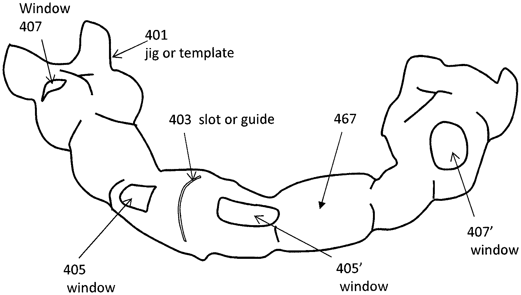
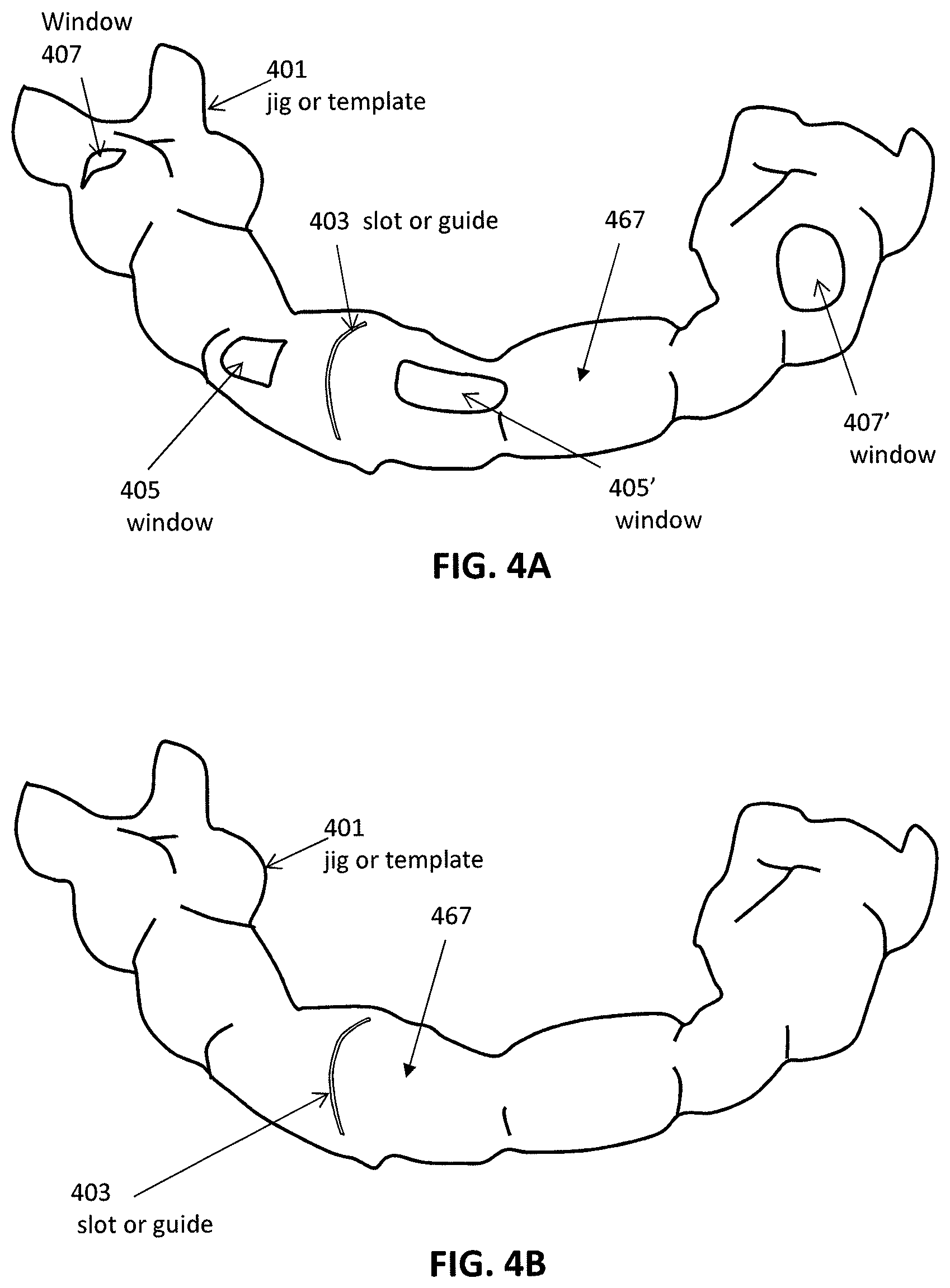
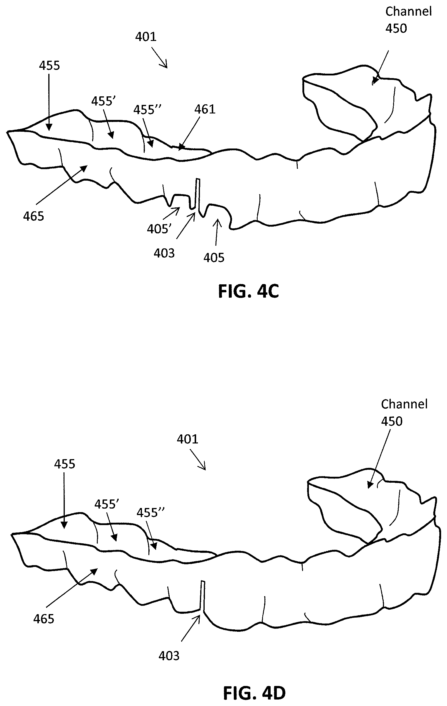
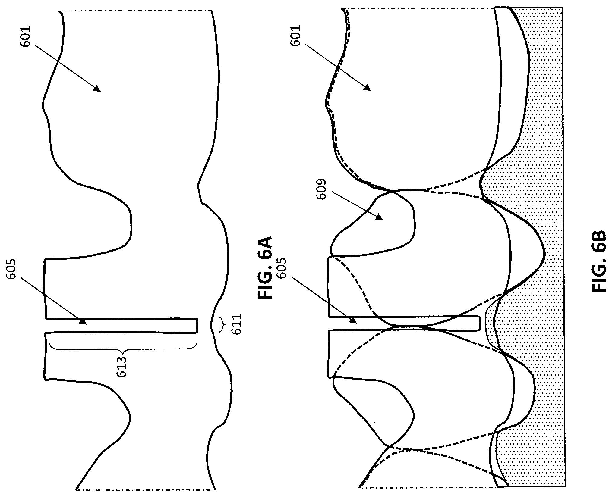
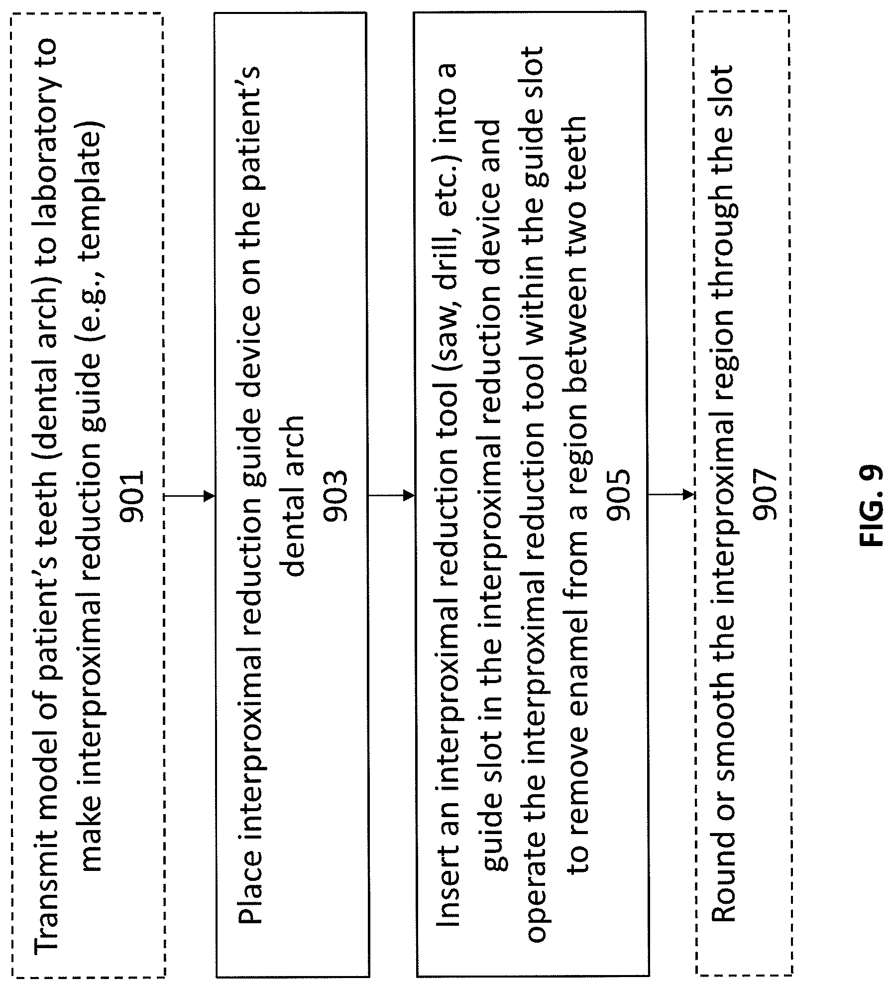
Interproximal reduction guides apparatuses and methods of making and using them are described herein. These interproximal reduction guides apparatuses may include a body that fits over the patient's dental arch and one or more guide slots formed in them configured to limit the motion of an interproximal reduction cutting tool in a defined manner.
| Inventors: | Grove; Bob (San Jose, CA), Kaza; Srinivas (Mountain View, CA) | ||||||||||
|---|---|---|---|---|---|---|---|---|---|---|---|
| Applicant: |
|
||||||||||
| Assignee: | Align Technology, Inc. (San
Jose, CA) |
||||||||||
| Family ID: | 1000005139650 | ||||||||||
| Appl. No.: | 15/726,243 | ||||||||||
| Filed: | October 5, 2017 |
Prior Publication Data
| Document Identifier | Publication Date | |
|---|---|---|
| US 20190105130 A1 | Apr 11, 2019 | |
| Current U.S. Class: | 1/1 |
| Current CPC Class: | A61C 7/125 (20130101); A61C 13/0006 (20130101); A61C 13/0004 (20130101); A61C 1/082 (20130101); A61C 7/02 (20130101); A61C 9/0093 (20130101); A61C 7/002 (20130101); A61C 5/44 (20170201); A61C 13/34 (20130101); A61C 13/0013 (20130101); A61C 3/06 (20130101) |
| Current International Class: | A61C 7/02 (20060101); A61C 7/00 (20060101); A61C 13/00 (20060101); A61C 1/08 (20060101); A61C 5/44 (20170101); A61C 13/34 (20060101); A61C 9/00 (20060101); A61C 7/12 (20060101); A61C 3/06 (20060101) |
References Cited [Referenced By]
U.S. Patent Documents
| 2171695 | September 1939 | Harper |
| 2194790 | March 1940 | Gluck |
| 2467432 | April 1949 | Kesling |
| 2531222 | November 1950 | Kesling |
| 3089487 | May 1963 | Enicks et al. |
| 3092907 | June 1963 | Traiger |
| 3178820 | April 1965 | Kesling |
| 3211143 | October 1965 | Grossberg |
| 3379193 | April 1968 | Monsghan |
| 3385291 | May 1968 | Martin |
| 3407500 | October 1968 | Kesling |
| 3478742 | November 1969 | Bohlmann |
| 3496936 | February 1970 | Gores |
| 3533163 | October 1970 | Kirschenbaum |
| 3556093 | January 1971 | Quick |
| 3600808 | August 1971 | Reeve |
| 3660900 | May 1972 | Andrews |
| 3683502 | August 1972 | Wallshein |
| 3724075 | April 1973 | Kesling |
| 3738005 | June 1973 | Cohen et al. |
| 3797115 | March 1974 | Silverman et al. |
| 3860803 | January 1975 | Levine |
| 3885310 | May 1975 | Northcutt |
| 3916526 | November 1975 | Schudy |
| 3922786 | December 1975 | Lavin |
| 3949477 | April 1976 | Cohen et al. |
| 3950851 | April 1976 | Bergersen |
| 3955282 | May 1976 | McNall |
| 3983628 | October 1976 | Acevedo |
| 4014096 | March 1977 | Dellinger |
| 4055895 | November 1977 | Huge |
| 4094068 | June 1978 | Schinhammer |
| 4117596 | October 1978 | Wallshein |
| 4129946 | December 1978 | Kennedy |
| 4134208 | January 1979 | Pearlman |
| 4139944 | February 1979 | Bergersen |
| 4179811 | December 1979 | Hinz |
| 4179812 | December 1979 | White |
| 4183141 | January 1980 | Dellinger |
| 4195046 | March 1980 | Kesling |
| 4204325 | May 1980 | Kaelble |
| 4253828 | March 1981 | Coles et al. |
| 4255138 | March 1981 | Frohn |
| 4299568 | November 1981 | Crowley |
| 4324546 | April 1982 | Heitlinger et al. |
| 4324547 | April 1982 | Arcan et al. |
| 4348178 | September 1982 | Kurz |
| 4368040 | January 1983 | Weissman |
| 4375965 | March 1983 | Weissman |
| 4419992 | December 1983 | Chorbajian |
| 4433956 | February 1984 | Witzig |
| 4433960 | February 1984 | Garito et al. |
| 4439154 | March 1984 | Mayclin |
| 4449928 | May 1984 | von Weissenfluh |
| 4478580 | October 1984 | Barrut |
| 4500294 | February 1985 | Lewis |
| 4505672 | March 1985 | Kurz |
| 4505673 | March 1985 | Yoshii |
| 4519386 | May 1985 | Sullivan |
| 4523908 | June 1985 | Drisaldi et al. |
| 4526540 | July 1985 | Dellinger |
| 4553936 | November 1985 | Wang |
| 4575330 | March 1986 | Hull |
| 4575805 | March 1986 | Moermann et al. |
| 4591341 | May 1986 | Andrews |
| 4608021 | August 1986 | Barrett |
| 4609349 | September 1986 | Cain |
| 4611288 | September 1986 | Duret et al. |
| 4629424 | December 1986 | Lauks et al. |
| 4638145 | January 1987 | Sakuma et al. |
| 4656860 | April 1987 | Orthuber et al. |
| 4663720 | May 1987 | Duret et al. |
| 4664626 | May 1987 | Kesling |
| 4665621 | May 1987 | Ackerman et al. |
| 4676747 | June 1987 | Kesling |
| 4755139 | July 1988 | Abbatte et al. |
| 4757824 | July 1988 | Chaumet |
| 4763791 | August 1988 | Halverson et al. |
| 4764111 | August 1988 | Knierim |
| 4790752 | December 1988 | Cheslak |
| 4793803 | December 1988 | Martz |
| 4798534 | January 1989 | Breads |
| 4830612 | May 1989 | Bergersen |
| 4836778 | June 1989 | Baumrind et al. |
| 4837732 | June 1989 | Brandestini et al. |
| 4850864 | July 1989 | Diamond |
| 4850865 | July 1989 | Napolitano |
| 4856991 | August 1989 | Breads et al. |
| 4877398 | October 1989 | Kesling |
| 4880380 | November 1989 | Martz |
| 4886451 | December 1989 | Cetlin |
| 4889238 | December 1989 | Batchelor |
| 4890608 | January 1990 | Steer |
| 4932866 | June 1990 | Guis |
| 4935635 | June 1990 | O'Harra |
| 4936862 | June 1990 | Walker et al. |
| 4937928 | July 1990 | van der Zel |
| 4941826 | July 1990 | Loran et al. |
| 4952928 | August 1990 | Carroll et al. |
| 4964770 | October 1990 | Steinbichler et al. |
| 4971557 | November 1990 | Martin |
| 4975052 | December 1990 | Spencer et al. |
| 4983334 | January 1991 | Adell |
| 4997369 | March 1991 | Shafir |
| 5002485 | March 1991 | Aagesen |
| 5011405 | April 1991 | Lemchen |
| 5015183 | May 1991 | Fenick |
| 5017133 | May 1991 | Miura |
| 5018969 | May 1991 | Andreiko et al. |
| 5027281 | June 1991 | Rekow et al. |
| 5035613 | July 1991 | Breads et al. |
| 5037295 | August 1991 | Bergersen |
| 5055039 | October 1991 | Abbatte |
| 5061839 | October 1991 | Matsuno et al. |
| 5083919 | January 1992 | Quachi |
| 5094614 | March 1992 | Wildman |
| 5100316 | March 1992 | Wildman |
| 5103838 | April 1992 | Yousif |
| 5114339 | May 1992 | Guis |
| 5121333 | June 1992 | Riley et al. |
| 5123425 | June 1992 | Shannon et al. |
| 5128870 | July 1992 | Erdman et al. |
| 5130064 | July 1992 | Smalley et al. |
| 5131843 | July 1992 | Hilgers et al. |
| 5131844 | July 1992 | Marinaccio et al. |
| 5139419 | August 1992 | Andreiko et al. |
| 5145364 | September 1992 | Martz et al. |
| 5176517 | January 1993 | Truax |
| 5194003 | March 1993 | Garay et al. |
| 5204670 | April 1993 | Stinton |
| 5222499 | June 1993 | Allen et al. |
| 5224049 | June 1993 | Mushabac |
| 5238404 | August 1993 | Andreiko |
| 5242304 | September 1993 | Truax et al. |
| 5245592 | September 1993 | Kuemmel et al. |
| 5273429 | December 1993 | Rekow et al. |
| 5278756 | January 1994 | Lemchen et al. |
| 5306144 | April 1994 | Hibst et al. |
| 5314335 | May 1994 | Fung |
| 5324186 | June 1994 | Bakanowski |
| 5328362 | July 1994 | Watson et al. |
| 5335657 | August 1994 | Terry et al. |
| 5338198 | August 1994 | Wu et al. |
| 5340309 | August 1994 | Robertson |
| 5342202 | August 1994 | Deshayes |
| 5344315 | September 1994 | Hanson |
| 5368478 | November 1994 | Andreiko et al. |
| 5372502 | December 1994 | Massen et al. |
| D354355 | January 1995 | Hilgers |
| 5382164 | January 1995 | Stern |
| 5395238 | March 1995 | Andreiko et al. |
| 5415542 | May 1995 | Kesling |
| 5431562 | July 1995 | Andreiko et al. |
| 5440326 | August 1995 | Quinn |
| 5440496 | August 1995 | Andersson et al. |
| 5447432 | September 1995 | Andreiko et al. |
| 5449703 | September 1995 | Mitra et al. |
| 5452219 | September 1995 | Dehoff et al. |
| 5454717 | October 1995 | Andreiko et al. |
| 5456600 | October 1995 | Andreiko et al. |
| 5474448 | December 1995 | Andreiko et al. |
| 5487662 | January 1996 | Kipke et al. |
| RE35169 | March 1996 | Lemchen et al. |
| 5499633 | March 1996 | Fenton |
| 5522725 | June 1996 | Jordan et al. |
| 5528735 | June 1996 | Strasnick et al. |
| 5533895 | July 1996 | Andreiko et al. |
| 5540732 | July 1996 | Testerman |
| 5542842 | August 1996 | Andreiko et al. |
| 5543780 | August 1996 | McAuley et al. |
| 5549476 | August 1996 | Stern |
| 5562448 | October 1996 | Mushabac |
| 5570182 | October 1996 | Nathel et al. |
| 5575655 | November 1996 | Darnell |
| 5583977 | December 1996 | Seidl |
| 5587912 | December 1996 | Andersson et al. |
| 5588098 | December 1996 | Chen et al. |
| 5605459 | February 1997 | Kuroda et al. |
| 5607305 | March 1997 | Andersson et al. |
| 5614075 | March 1997 | Andre |
| 5621648 | April 1997 | Crump |
| 5626537 | May 1997 | Danyo et al. |
| 5636736 | June 1997 | Jacobs et al. |
| 5645420 | July 1997 | Bergersen |
| 5645421 | July 1997 | Slootsky |
| 5651671 | July 1997 | Seay et al. |
| 5655653 | August 1997 | Chester |
| 5659420 | August 1997 | Wakai et al. |
| 5683243 | November 1997 | Andreiko et al. |
| 5683244 | November 1997 | Truax |
| 5691539 | November 1997 | Pfeiffer |
| 5692894 | December 1997 | Schwartz et al. |
| 5711665 | January 1998 | Adam et al. |
| 5711666 | January 1998 | Hanson |
| 5725376 | March 1998 | Poirier |
| 5725378 | March 1998 | Wang |
| 5730151 | March 1998 | Summer et al. |
| 5737084 | April 1998 | Ishihara |
| 5740267 | April 1998 | Echerer et al. |
| 5742700 | April 1998 | Yoon et al. |
| 5769631 | June 1998 | Williams |
| 5774425 | June 1998 | Ivanov et al. |
| 5790242 | August 1998 | Stern et al. |
| 5799100 | August 1998 | Clarke et al. |
| 5800162 | September 1998 | Shimodaira et al. |
| 5800174 | September 1998 | Andersson |
| 5813854 | September 1998 | Nikodem |
| 5816800 | October 1998 | Brehm et al. |
| 5818587 | October 1998 | Devaraj et al. |
| 5823778 | October 1998 | Schmitt et al. |
| 5848115 | December 1998 | Little et al. |
| 5857853 | January 1999 | van Nifterick et al. |
| 5866058 | February 1999 | Batchelder et al. |
| 5876199 | March 1999 | Bergersen |
| 5879158 | March 1999 | Doyle et al. |
| 5880961 | March 1999 | Crump |
| 5880962 | March 1999 | Andersson et al. |
| 5882192 | March 1999 | Bergersen |
| 5886702 | March 1999 | Migdal et al. |
| 5890896 | April 1999 | Padial |
| 5904479 | May 1999 | Staples |
| 5934288 | August 1999 | Avila et al. |
| 5957686 | September 1999 | Anthony |
| 5964587 | October 1999 | Sato |
| 5971754 | October 1999 | Sondhi et al. |
| 5975893 | November 1999 | Chishti et al. |
| 5975906 | November 1999 | Knutson |
| 5980246 | November 1999 | Ramsay et al. |
| 5989023 | November 1999 | Summer et al. |
| 6002706 | December 1999 | Stayer et al. |
| 6018713 | January 2000 | Coli et al. |
| 6044309 | March 2000 | Honda |
| 6049743 | April 2000 | Baba |
| 6053731 | April 2000 | Heckenberger |
| 6068482 | May 2000 | Snow |
| 6070140 | May 2000 | Tran |
| 6099303 | August 2000 | Gibbs et al. |
| 6099314 | August 2000 | Kopelman et al. |
| 6102701 | August 2000 | Engeron |
| 6120287 | September 2000 | Chen |
| 6123544 | September 2000 | Cleary |
| 6152731 | November 2000 | Jordan et al. |
| 6154676 | November 2000 | Levine |
| 6183248 | February 2001 | Chishti et al. |
| 6183249 | February 2001 | Brennan et al. |
| 6186780 | February 2001 | Hibst et al. |
| 6190165 | February 2001 | Andreiko et al. |
| 6200133 | March 2001 | Kittelsen |
| 6201880 | March 2001 | Elbaum et al. |
| 6210162 | April 2001 | Chishti et al. |
| 6212435 | April 2001 | Lattner et al. |
| 6213767 | April 2001 | Dixon et al. |
| 6217334 | April 2001 | Hultgren |
| 6227850 | May 2001 | Chishti et al. |
| 6231338 | May 2001 | de Josselin de Jong et al. |
| 6239705 | May 2001 | Glen |
| 6243601 | June 2001 | Wist |
| 6263234 | July 2001 | Engelhardt et al. |
| 6283761 | September 2001 | Joao |
| 6288138 | September 2001 | Yamamoto |
| 6299438 | October 2001 | Sahagian et al. |
| 6309215 | October 2001 | Phan et al. |
| 6313432 | November 2001 | Nagata et al. |
| 6315553 | November 2001 | Sachdeva et al. |
| 6328745 | December 2001 | Ascherman |
| 6332774 | December 2001 | Chikami |
| 6334073 | December 2001 | Levine |
| 6350120 | February 2002 | Sachdeva et al. |
| 6364660 | April 2002 | Durbin et al. |
| 6382975 | May 2002 | Poirier |
| 6386878 | May 2002 | Pavlovskaia et al. |
| 6394802 | May 2002 | Hahn |
| 6402510 | June 2002 | Williams |
| 6402707 | June 2002 | Ernst |
| 6405729 | June 2002 | Thornton |
| 6406292 | June 2002 | Chishti et al. |
| 6409504 | June 2002 | Jones et al. |
| 6413086 | July 2002 | Womack |
| 6414264 | July 2002 | von Falkenhausen |
| 6414708 | July 2002 | Carmeli et al. |
| 6435871 | August 2002 | Inman |
| 6436058 | August 2002 | Krahner et al. |
| 6441354 | August 2002 | Seghatol et al. |
| 6450167 | September 2002 | David et al. |
| 6450807 | September 2002 | Chishti et al. |
| 6462301 | October 2002 | Scott et al. |
| 6470338 | October 2002 | Rizzo et al. |
| 6471511 | October 2002 | Chishti et al. |
| 6471512 | October 2002 | Sachdeva et al. |
| 6471970 | October 2002 | Fanara et al. |
| 6482002 | November 2002 | Jordan et al. |
| 6482298 | November 2002 | Bhatnagar |
| 6496814 | December 2002 | Busche |
| 6496816 | December 2002 | Thiesson et al. |
| 6499026 | December 2002 | Rivette et al. |
| 6499995 | December 2002 | Schwartz |
| 6507832 | January 2003 | Evans et al. |
| 6514074 | February 2003 | Chishti et al. |
| 6515593 | February 2003 | Stark et al. |
| 6516288 | February 2003 | Bagne |
| 6516805 | February 2003 | Thornton |
| 6520772 | February 2003 | Williams |
| 6523009 | February 2003 | Wilkins |
| 6523019 | February 2003 | Borthwick |
| 6524101 | February 2003 | Phan et al. |
| 6526168 | February 2003 | Ornes et al. |
| 6526982 | March 2003 | Strong |
| 6529891 | March 2003 | Heckerman |
| 6529902 | March 2003 | Kanevsky et al. |
| 6532455 | March 2003 | Martin et al. |
| 6535865 | March 2003 | Skaaning et al. |
| 6540512 | April 2003 | Sachdeva et al. |
| 6540707 | April 2003 | Stark et al. |
| 6542593 | April 2003 | Bowman Amuah |
| 6542881 | April 2003 | Meidan et al. |
| 6542894 | April 2003 | Lee et al. |
| 6542903 | April 2003 | Hull et al. |
| 6551243 | April 2003 | Bocionek et al. |
| 6554837 | April 2003 | Hauri et al. |
| 6556659 | April 2003 | Bowman Amuah |
| 6556977 | April 2003 | Lapointe et al. |
| 6560592 | May 2003 | Reid et al. |
| 6564209 | May 2003 | Dempski et al. |
| 6567814 | May 2003 | Bankier et al. |
| 6571227 | May 2003 | Agrafiotis et al. |
| 6572372 | June 2003 | Phan et al. |
| 6573998 | June 2003 | Cohen Sabban |
| 6574561 | June 2003 | Alexander et al. |
| 6578003 | June 2003 | Camarda et al. |
| 6580948 | June 2003 | Haupert et al. |
| 6587529 | July 2003 | Staszewski et al. |
| 6587828 | July 2003 | Sachdeva |
| 6592368 | July 2003 | Weathers |
| 6594539 | July 2003 | Geng |
| 6595342 | July 2003 | Maritzen et al. |
| 6597934 | July 2003 | de Jong et al. |
| 6598043 | July 2003 | Baclawski |
| 6599250 | July 2003 | Webb et al. |
| 6602070 | August 2003 | Miller et al. |
| 6604527 | August 2003 | Palmisano |
| 6606744 | August 2003 | Mikurak |
| 6607382 | August 2003 | Kuo et al. |
| 6611783 | August 2003 | Kelly et al. |
| 6611867 | August 2003 | Bowman Amuah |
| 6613001 | September 2003 | Dworkin |
| 6615158 | September 2003 | Wenzel et al. |
| 6616447 | September 2003 | Rizoiu et al. |
| 6616579 | September 2003 | Reinbold et al. |
| 6621491 | September 2003 | Baumrind et al. |
| 6623698 | September 2003 | Kuo |
| 6624752 | September 2003 | Klitsgaard et al. |
| 6626180 | September 2003 | Kittelsen et al. |
| 6626569 | September 2003 | Reinstein et al. |
| 6626669 | September 2003 | Zegarelli |
| 6633772 | October 2003 | Ford et al. |
| 6640128 | October 2003 | Vilsmeier et al. |
| 6643646 | November 2003 | Su et al. |
| 6647383 | November 2003 | August et al. |
| 6650944 | November 2003 | Goedeke et al. |
| 6671818 | December 2003 | Mikurak |
| 6675104 | January 2004 | Paulse et al. |
| 6678669 | January 2004 | Lapointe et al. |
| 6682346 | January 2004 | Chishti |
| 6685469 | February 2004 | Chishti et al. |
| 6689055 | February 2004 | Mullen et al. |
| 6690761 | February 2004 | Lang et al. |
| 6691110 | February 2004 | Wang et al. |
| 6694234 | February 2004 | Lockwood et al. |
| 6697164 | February 2004 | Babayoff et al. |
| 6697793 | February 2004 | McGreevy |
| 6702765 | March 2004 | Robbins et al. |
| 6702804 | March 2004 | Ritter et al. |
| 6705863 | March 2004 | Phan et al. |
| 6729876 | May 2004 | Chishti et al. |
| 6733289 | May 2004 | Manemann et al. |
| 6736638 | May 2004 | Sachdeva et al. |
| 6739869 | May 2004 | Taub et al. |
| 6744932 | June 2004 | Rubbert et al. |
| 6749414 | June 2004 | Hanson et al. |
| 6769913 | August 2004 | Hurson |
| 6772026 | August 2004 | Bradbury et al. |
| 6790036 | September 2004 | Graham |
| 6802713 | October 2004 | Chishti et al. |
| 6814574 | November 2004 | Abolfathi et al. |
| 6830450 | December 2004 | Knopp et al. |
| 6832912 | December 2004 | Mao |
| 6832914 | December 2004 | Bonnet et al. |
| 6843370 | January 2005 | Tuneberg |
| 6845175 | January 2005 | Kopelman et al. |
| 6885464 | April 2005 | Pfeiffer et al. |
| 6890285 | May 2005 | Rahman et al. |
| 6951254 | October 2005 | Morrison |
| 6976841 | December 2005 | Osterwalder |
| 6978268 | December 2005 | Thomas et al. |
| 6983752 | January 2006 | Garabadian |
| 6984128 | January 2006 | Breining et al. |
| 6988893 | January 2006 | Haywood |
| 7016952 | March 2006 | Mullen et al. |
| 7020963 | April 2006 | Cleary et al. |
| 7036514 | May 2006 | Heck |
| 7040896 | May 2006 | Pavlovskaia et al. |
| 7106233 | September 2006 | Schroeder et al. |
| 7112065 | September 2006 | Kopelman et al. |
| 7121825 | October 2006 | Chishti et al. |
| 7134874 | November 2006 | Chishti et al. |
| 7137812 | November 2006 | Cleary et al. |
| 7138640 | November 2006 | Delgado et al. |
| 7140877 | November 2006 | Kaza |
| 7142312 | November 2006 | Quadling et al. |
| 7155373 | December 2006 | Jordan et al. |
| 7156655 | January 2007 | Sachdeva et al. |
| 7156661 | January 2007 | Choi et al. |
| 7166063 | January 2007 | Rahman et al. |
| 7184150 | February 2007 | Quadling et al. |
| 7191451 | March 2007 | Nakagawa |
| 7192273 | March 2007 | McSurdy |
| 7217131 | May 2007 | Vuillemot |
| 7220122 | May 2007 | Chishti |
| 7220124 | May 2007 | Taub et al. |
| 7229282 | June 2007 | Andreiko et al. |
| 7234937 | June 2007 | Sachdeva et al. |
| 7241142 | July 2007 | Abolfathi et al. |
| 7244230 | July 2007 | Duggirala et al. |
| 7245753 | July 2007 | Squilla et al. |
| 7257136 | August 2007 | Mori et al. |
| 7286954 | October 2007 | Kopelman et al. |
| 7292759 | November 2007 | Boutoussov et al. |
| 7294141 | November 2007 | Bergersen |
| 7302842 | December 2007 | Biester et al. |
| 7320592 | January 2008 | Chishti et al. |
| 7328706 | February 2008 | Barach et al. |
| 7329122 | February 2008 | Scott |
| 7338327 | March 2008 | Sticker et al. |
| D565509 | April 2008 | Fechner et al. |
| 7351116 | April 2008 | Dold |
| 7354270 | April 2008 | Abolfathi et al. |
| 7357637 | April 2008 | Liechtung |
| 7435083 | October 2008 | Chishti et al. |
| 7450231 | November 2008 | Johs et al. |
| 7458810 | December 2008 | Bergersen |
| 7460230 | December 2008 | Johs et al. |
| 7462076 | December 2008 | Walter et al. |
| 7463929 | December 2008 | Simmons |
| 7476100 | January 2009 | Kuo |
| 7500851 | March 2009 | Williams |
| D594413 | June 2009 | Palka et al. |
| 7543511 | June 2009 | Kimura et al. |
| 7544103 | June 2009 | Walter et al. |
| 7553157 | June 2009 | Abolfathi et al. |
| 7561273 | July 2009 | Stautmeister et al. |
| 7577284 | August 2009 | Wong et al. |
| 7596253 | September 2009 | Wong et al. |
| 7597594 | October 2009 | Stadler et al. |
| 7609875 | October 2009 | Liu et al. |
| D603796 | November 2009 | Sticker et al. |
| 7616319 | November 2009 | Woollam et al. |
| 7626705 | December 2009 | Altendorf |
| 7632216 | December 2009 | Rahman et al. |
| 7633625 | December 2009 | Woollam et al. |
| 7637262 | December 2009 | Bailey |
| 7637740 | December 2009 | Knopp |
| 7641473 | January 2010 | Sporbert et al. |
| 7668355 | February 2010 | Wong et al. |
| 7670179 | March 2010 | Muller |
| 7695327 | April 2010 | Bauerle et al. |
| 7698068 | April 2010 | Babayoff |
| 7711447 | May 2010 | Lu et al. |
| 7724378 | May 2010 | Babayoff |
| D618619 | June 2010 | Walter |
| 7728848 | June 2010 | Petrov et al. |
| 7731508 | June 2010 | Borst |
| 7735217 | June 2010 | Borst |
| 7740476 | June 2010 | Rubbert et al. |
| 7744369 | June 2010 | Imgrund et al. |
| 7746339 | June 2010 | Matov et al. |
| 7780460 | August 2010 | Walter |
| 7787132 | August 2010 | Korner et al. |
| 7791810 | September 2010 | Powell |
| 7796243 | September 2010 | Choo-Smith et al. |
| 7806687 | October 2010 | Minagi et al. |
| 7806727 | October 2010 | Dold et al. |
| 7813787 | October 2010 | de Josselin de Jong et al. |
| 7824180 | November 2010 | Abolfathi et al. |
| 7828601 | November 2010 | Pyczak |
| 7841464 | November 2010 | Cinader et al. |
| 7845969 | December 2010 | Stadler et al. |
| 7854609 | December 2010 | Chen et al. |
| 7862336 | January 2011 | Kopelman et al. |
| 7869983 | January 2011 | Raby et al. |
| 7872760 | January 2011 | Ertl |
| 7874836 | January 2011 | McSurdy |
| 7874837 | January 2011 | Chishti et al. |
| 7874849 | January 2011 | Sticker et al. |
| 7878801 | February 2011 | Abolfathi et al. |
| 7878805 | February 2011 | Moss et al. |
| 7880751 | February 2011 | Kuo et al. |
| 7892474 | February 2011 | Shkolnik et al. |
| 7904308 | March 2011 | Arnone et al. |
| 7907280 | March 2011 | Johs et al. |
| 7929151 | April 2011 | Liang et al. |
| 7930189 | April 2011 | Kuo |
| 7947508 | May 2011 | Tricca et al. |
| 7959308 | June 2011 | Freeman et al. |
| 7963766 | June 2011 | Cronauer |
| 7970627 | June 2011 | Kuo et al. |
| 7985414 | July 2011 | Knaack et al. |
| 7986415 | July 2011 | Thiel et al. |
| 7987099 | July 2011 | Kuo et al. |
| 7991485 | August 2011 | Zakim |
| 8017891 | September 2011 | Nevin |
| 8026916 | September 2011 | Wen |
| 8027709 | September 2011 | Arnone et al. |
| 8029277 | October 2011 | Imgrund et al. |
| 8038444 | October 2011 | Kitching et al. |
| 8045772 | October 2011 | Kosuge et al. |
| 8054556 | November 2011 | Chen et al. |
| 8070490 | December 2011 | Roetzer et al. |
| 8075306 | December 2011 | Kitching et al. |
| 8077949 | December 2011 | Liang et al. |
| 8083556 | December 2011 | Stadler et al. |
| D652799 | January 2012 | Mueller |
| 8092215 | January 2012 | Stone-Collonge et al. |
| 8095383 | January 2012 | Arnone et al. |
| 8099268 | January 2012 | Kitching et al. |
| 8099305 | January 2012 | Kuo et al. |
| 8118592 | February 2012 | Tortorici |
| 8126025 | February 2012 | Takeda |
| 8136629 | March 2012 | Kelly |
| 8144954 | March 2012 | Quadling et al. |
| 8160334 | April 2012 | Thiel et al. |
| 8172569 | May 2012 | Matty et al. |
| 8197252 | June 2012 | Harrison |
| 8201560 | June 2012 | Dembro |
| 8215312 | July 2012 | Garabadian et al. |
| 8240018 | August 2012 | Walter et al. |
| 8275180 | September 2012 | Kuo |
| 8279450 | October 2012 | Oota et al. |
| 8292617 | October 2012 | Brandt et al. |
| 8294657 | October 2012 | Kim et al. |
| 8296952 | October 2012 | Greenberg |
| 8297286 | October 2012 | Smernoff |
| 8306608 | November 2012 | Mandelis et al. |
| 8314764 | November 2012 | Kim et al. |
| 8332015 | December 2012 | Ertl |
| 8354588 | January 2013 | Sticker et al. |
| 8366479 | February 2013 | Borst et al. |
| 8401826 | March 2013 | Cheng et al. |
| 8419428 | April 2013 | Lawrence |
| 8433083 | April 2013 | Abolfathi et al. |
| 8439672 | May 2013 | Matov et al. |
| 8465280 | June 2013 | Sachdeva et al. |
| 8477320 | July 2013 | Stock et al. |
| 8488113 | July 2013 | Thiel et al. |
| 8517726 | August 2013 | Kakavand et al. |
| 8520922 | August 2013 | Wang et al. |
| 8520925 | August 2013 | Duret et al. |
| 8523565 | September 2013 | Matty et al. |
| 8545221 | October 2013 | Stone-Collonge et al. |
| 8556625 | October 2013 | Lovely |
| 8570530 | October 2013 | Liang |
| 8573224 | November 2013 | Thornton |
| 8577212 | November 2013 | Thiel |
| 8601925 | December 2013 | Coto |
| 8639477 | January 2014 | Chelnokov et al. |
| 8650586 | February 2014 | Lee et al. |
| 8675706 | March 2014 | Seurin et al. |
| 8723029 | May 2014 | Pyczak et al. |
| 8738394 | May 2014 | Kuo |
| 8743923 | June 2014 | Geske et al. |
| 8753114 | June 2014 | Vuillemot |
| 8767270 | July 2014 | Curry et al. |
| 8768016 | July 2014 | Pan et al. |
| 8771149 | July 2014 | Rahman et al. |
| 8839476 | September 2014 | Adachi |
| 8843381 | September 2014 | Kuo et al. |
| 8856053 | October 2014 | Mah |
| 8870566 | October 2014 | Bergersen |
| 8874452 | October 2014 | Kuo |
| 8878905 | November 2014 | Fisker et al. |
| 8899976 | December 2014 | Chen et al. |
| 8936463 | January 2015 | Mason et al. |
| 8944812 | February 2015 | Kou |
| 8948482 | February 2015 | Levin |
| 8956058 | February 2015 | Rosch |
| 8992216 | March 2015 | Karazivan |
| 9004915 | April 2015 | Moss et al. |
| 9022792 | May 2015 | Sticker et al. |
| 9039418 | May 2015 | Rubbert |
| 9084535 | July 2015 | Girkin et al. |
| 9084657 | July 2015 | Matty et al. |
| 9108338 | August 2015 | Sirovskiy et al. |
| 9144512 | September 2015 | Wagner |
| 9192305 | November 2015 | Levin |
| 9204952 | December 2015 | Lampalzer |
| 9211166 | December 2015 | Kuo et al. |
| 9214014 | December 2015 | Levin |
| 9220580 | December 2015 | Borovinskih et al. |
| 9241774 | January 2016 | Li et al. |
| 9242118 | January 2016 | Brawn |
| 9261358 | February 2016 | Atiya et al. |
| 9277972 | March 2016 | Brandt et al. |
| 9336336 | May 2016 | Deichmann et al. |
| 9351810 | May 2016 | Moon |
| 9375300 | June 2016 | Matov et al. |
| 9403238 | August 2016 | Culp |
| 9408743 | August 2016 | Wagner |
| 9414897 | August 2016 | Wu et al. |
| 9433476 | September 2016 | Khardekar et al. |
| 9439568 | September 2016 | Atiya et al. |
| 9444981 | September 2016 | Bellis et al. |
| 9463287 | October 2016 | Lorberbaum et al. |
| 9492243 | November 2016 | Kuo |
| 9500635 | November 2016 | Islam |
| 9506808 | November 2016 | Jeon et al. |
| 9510918 | December 2016 | Sanchez |
| 9545331 | January 2017 | Ingemarsson-Matzen |
| 9566132 | February 2017 | Stone-Collonge et al. |
| 9584771 | February 2017 | Mandelis et al. |
| 9589329 | March 2017 | Levin |
| 9675427 | June 2017 | Kopelman |
| 9675430 | June 2017 | Verker et al. |
| 9693839 | July 2017 | Atiya et al. |
| 9730769 | August 2017 | Chen et al. |
| 9744006 | August 2017 | Ross |
| 9820829 | November 2017 | Kuo |
| 9830688 | November 2017 | Levin |
| 9844421 | December 2017 | Moss et al. |
| 9848985 | December 2017 | Yang et al. |
| 9861451 | January 2018 | Davis |
| 9936186 | April 2018 | Jesenko et al. |
| 10123853 | November 2018 | Moss et al. |
| 10154889 | December 2018 | Chen et al. |
| 10159541 | December 2018 | Bindayel |
| 10172693 | January 2019 | Brandt et al. |
| 10195690 | February 2019 | Culp |
| 10231801 | March 2019 | Korytov et al. |
| 10238472 | March 2019 | Levin |
| 10258432 | April 2019 | Webber |
| 2001/0002310 | May 2001 | Chishti et al. |
| 2001/0032100 | October 2001 | Mahmud et al. |
| 2001/0038705 | November 2001 | Rubbert et al. |
| 2001/0041320 | November 2001 | Phan |
| 2002/0004727 | January 2002 | Knaus et al. |
| 2002/0007284 | January 2002 | Schurenberg et al. |
| 2002/0010568 | January 2002 | Rubbert et al. |
| 2002/0015934 | February 2002 | Rubbert et al. |
| 2002/0025503 | February 2002 | Chapoulaud et al. |
| 2002/0026105 | February 2002 | Drazen |
| 2002/0028417 | March 2002 | Chapoulaud et al. |
| 2002/0035572 | March 2002 | Takatori et al. |
| 2002/0064752 | May 2002 | Durbin et al. |
| 2002/0064759 | May 2002 | Durbin et al. |
| 2002/0087551 | July 2002 | Hickey et al. |
| 2002/0107853 | August 2002 | Hofmann et al. |
| 2002/0188478 | December 2002 | Breeland et al. |
| 2002/0192617 | December 2002 | Phan et al. |
| 2003/0000927 | January 2003 | Kanaya et al. |
| 2003/0009252 | January 2003 | Pavlovskaia et al. |
| 2003/0019848 | January 2003 | Nicholas et al. |
| 2003/0021453 | January 2003 | Weise et al. |
| 2003/0035061 | February 2003 | Iwaki et al. |
| 2003/0049581 | March 2003 | Deluke |
| 2003/0057192 | March 2003 | Patel |
| 2003/0059736 | March 2003 | Lai et al. |
| 2003/0060532 | March 2003 | Subelka et al. |
| 2003/0068598 | April 2003 | Vallittu et al. |
| 2003/0095697 | May 2003 | Wood et al. |
| 2003/0101079 | May 2003 | McLaughlin |
| 2003/0103060 | June 2003 | Anderson et al. |
| 2003/0120517 | June 2003 | Eida et al. |
| 2003/0139834 | July 2003 | Nikolskiy et al. |
| 2003/0144886 | July 2003 | Taira |
| 2003/0172043 | September 2003 | Guyon et al. |
| 2003/0190575 | October 2003 | Hilliard |
| 2003/0192867 | October 2003 | Yamazaki et al. |
| 2003/0207224 | November 2003 | Lotte |
| 2003/0215764 | November 2003 | Kopelman et al. |
| 2003/0224311 | December 2003 | Cronauer |
| 2003/0224313 | December 2003 | Bergersen |
| 2003/0224314 | December 2003 | Bergersen |
| 2004/0002873 | January 2004 | Sachdeva |
| 2004/0009449 | January 2004 | Mah et al. |
| 2004/0013994 | January 2004 | Goldberg et al. |
| 2004/0019262 | January 2004 | Perelgut |
| 2004/0029078 | February 2004 | Marshall |
| 2004/0038168 | February 2004 | Choi et al. |
| 2004/0054304 | March 2004 | Raby |
| 2004/0054358 | March 2004 | Cox et al. |
| 2004/0058295 | March 2004 | Bergersen |
| 2004/0068199 | April 2004 | Echauz et al. |
| 2004/0078222 | April 2004 | Khan et al. |
| 2004/0080621 | April 2004 | Fisher et al. |
| 2004/0094165 | May 2004 | Cook |
| 2004/0107118 | June 2004 | Harnsberger et al. |
| 2004/0133083 | July 2004 | Comaniciu et al. |
| 2004/0152036 | August 2004 | Abolfathi |
| 2004/0158194 | August 2004 | Wolff et al. |
| 2004/0166463 | August 2004 | Wen et al. |
| 2004/0167646 | August 2004 | Jelonek et al. |
| 2004/0170941 | September 2004 | Phan et al. |
| 2004/0193036 | September 2004 | Zhou et al. |
| 2004/0197728 | October 2004 | Abolfathi et al. |
| 2004/0214128 | October 2004 | Sachdeva et al. |
| 2004/0219479 | November 2004 | Malin et al. |
| 2004/0220691 | November 2004 | Hofmeister et al. |
| 2004/0229185 | November 2004 | Knopp |
| 2004/0259049 | December 2004 | Kopelman et al. |
| 2005/0003318 | January 2005 | Choi et al. |
| 2005/0023356 | February 2005 | Wiklof et al. |
| 2005/0031196 | February 2005 | Moghaddam et al. |
| 2005/0037312 | February 2005 | Uchida |
| 2005/0038669 | February 2005 | Sachdeva et al. |
| 2005/0040551 | February 2005 | Biegler et al. |
| 2005/0042569 | February 2005 | Plan et al. |
| 2005/0042577 | February 2005 | Kvitrud et al. |
| 2005/0048433 | March 2005 | Hilliard |
| 2005/0074717 | April 2005 | Cleary et al. |
| 2005/0089822 | April 2005 | Geng |
| 2005/0100333 | May 2005 | Kerschbaumer et al. |
| 2005/0108052 | May 2005 | Omaboe |
| 2005/0131738 | June 2005 | Morris |
| 2005/0144150 | June 2005 | Ramamurthy et al. |
| 2005/0171594 | August 2005 | Machan et al. |
| 2005/0171630 | August 2005 | Dinauer et al. |
| 2005/0181333 | August 2005 | Karazivan et al. |
| 2005/0186524 | August 2005 | Abolfathi et al. |
| 2005/0186526 | August 2005 | Stewart et al. |
| 2005/0216314 | September 2005 | Secor |
| 2005/0233276 | October 2005 | Kopelman |
| 2005/0239013 | October 2005 | Sachdeva |
| 2005/0244781 | November 2005 | Abels et al. |
| 2005/0244791 | November 2005 | Davis et al. |
| 2005/0271996 | December 2005 | Sporbert et al. |
| 2006/0056670 | March 2006 | Hamadeh |
| 2006/0057533 | March 2006 | McGann |
| 2006/0063135 | March 2006 | Mehl |
| 2006/0078842 | April 2006 | Sachdeva et al. |
| 2006/0084024 | April 2006 | Farrell |
| 2006/0093982 | May 2006 | Wen |
| 2006/0098007 | May 2006 | Rouet et al. |
| 2006/0099545 | May 2006 | Lia et al. |
| 2006/0099546 | May 2006 | Bergersen |
| 2006/0110698 | May 2006 | Robson |
| 2006/0111631 | May 2006 | Kelliher et al. |
| 2006/0115785 | June 2006 | Li et al. |
| 2006/0137813 | June 2006 | Robrecht et al. |
| 2006/0147872 | July 2006 | Andreiko |
| 2006/0154198 | July 2006 | Durbin et al. |
| 2006/0154207 | July 2006 | Kuo |
| 2006/0173715 | August 2006 | Wang |
| 2006/0183082 | August 2006 | Quadling et al. |
| 2006/0188834 | August 2006 | Hilliard |
| 2006/0188848 | August 2006 | Tricca et al. |
| 2006/0194163 | August 2006 | Tricca et al. |
| 2006/0199153 | September 2006 | Liu et al. |
| 2006/0204078 | September 2006 | Orth et al. |
| 2006/0223022 | October 2006 | Solomon |
| 2006/0223023 | October 2006 | Lai et al. |
| 2006/0223032 | October 2006 | Fried et al. |
| 2006/0223342 | October 2006 | Borst et al. |
| 2006/0234179 | October 2006 | Wen et al. |
| 2006/0257815 | November 2006 | De Dominicis |
| 2006/0275729 | December 2006 | Fornoff |
| 2006/0275731 | December 2006 | Wen et al. |
| 2006/0275736 | December 2006 | Wen et al. |
| 2006/0277075 | December 2006 | Salwan |
| 2006/0290693 | December 2006 | Zhou et al. |
| 2006/0292520 | December 2006 | Dillon et al. |
| 2007/0031775 | February 2007 | Andreiko |
| 2007/0046865 | March 2007 | Umeda et al. |
| 2007/0053048 | March 2007 | Kumar et al. |
| 2007/0054237 | March 2007 | Neuschafer |
| 2007/0065768 | March 2007 | Nadav |
| 2007/0087300 | April 2007 | Willison et al. |
| 2007/0087302 | April 2007 | Reising et al. |
| 2007/0106138 | May 2007 | Beiski et al. |
| 2007/0122592 | May 2007 | Anderson et al. |
| 2007/0128574 | June 2007 | Kuo et al. |
| 2007/0141525 | June 2007 | Cinader, Jr. |
| 2007/0141526 | June 2007 | Eisenberg et al. |
| 2007/0143135 | June 2007 | Lindquist et al. |
| 2007/0168152 | July 2007 | Matov et al. |
| 2007/0172112 | July 2007 | Paley et al. |
| 2007/0172291 | July 2007 | Yokoyama |
| 2007/0178420 | August 2007 | Keski-Nisula et al. |
| 2007/0183633 | August 2007 | Hoffmann |
| 2007/0184402 | August 2007 | Boutoussov et al. |
| 2007/0185732 | August 2007 | Hicks et al. |
| 2007/0192137 | August 2007 | Ombrellaro |
| 2007/0199929 | August 2007 | Rippl et al. |
| 2007/0215582 | September 2007 | Roeper et al. |
| 2007/0218422 | September 2007 | Ehrenfeld |
| 2007/0231765 | October 2007 | Phan et al. |
| 2007/0238065 | October 2007 | Sherwood et al. |
| 2007/0239488 | October 2007 | DeRosso |
| 2007/0263226 | November 2007 | Kurtz et al. |
| 2008/0013727 | January 2008 | Uemura |
| 2008/0020350 | January 2008 | Matov et al. |
| 2008/0045053 | February 2008 | Stadler et al. |
| 2008/0050693 | February 2008 | Fischer |
| 2008/0057461 | March 2008 | Cheng et al. |
| 2008/0057467 | March 2008 | Gittelson |
| 2008/0057479 | March 2008 | Grenness |
| 2008/0059238 | March 2008 | Park et al. |
| 2008/0090208 | April 2008 | Rubbert |
| 2008/0094389 | April 2008 | Rouet et al. |
| 2008/0113317 | May 2008 | Kemp et al. |
| 2008/0115791 | May 2008 | Heine |
| 2008/0118882 | May 2008 | Su |
| 2008/0118886 | May 2008 | Liang et al. |
| 2008/0141534 | June 2008 | Hilliard |
| 2008/0171934 | July 2008 | Greenan et al. |
| 2008/0176448 | July 2008 | Muller et al. |
| 2008/0233530 | September 2008 | Cinader |
| 2008/0242144 | October 2008 | Dietz |
| 2008/0248443 | October 2008 | Chishti et al. |
| 2008/0254403 | October 2008 | Hilliard |
| 2008/0268400 | October 2008 | Moss et al. |
| 2008/0306724 | December 2008 | Kitching et al. |
| 2009/0014013 | January 2009 | Magnin |
| 2009/0029310 | January 2009 | Pumphrey et al. |
| 2009/0030290 | January 2009 | Kozuch et al. |
| 2009/0030347 | January 2009 | Cao |
| 2009/0040740 | February 2009 | Muller et al. |
| 2009/0061379 | March 2009 | Yamamoto et al. |
| 2009/0061381 | March 2009 | Durbin et al. |
| 2009/0075228 | March 2009 | Kaneko et al. |
| 2009/0087050 | April 2009 | Gandyra |
| 2009/0098502 | April 2009 | Andreiko |
| 2009/0099445 | April 2009 | Burger |
| 2009/0103579 | April 2009 | Ushimaru et al. |
| 2009/0105523 | April 2009 | Kassayan et al. |
| 2009/0130620 | May 2009 | Yazdi et al. |
| 2009/0136890 | May 2009 | Kang et al. |
| 2009/0136893 | May 2009 | Zegarelli |
| 2009/0148809 | June 2009 | Kuo et al. |
| 2009/0170050 | July 2009 | Marcus |
| 2009/0181346 | July 2009 | Orth |
| 2009/0191502 | July 2009 | Cao et al. |
| 2009/0210032 | August 2009 | Beiski et al. |
| 2009/0218514 | September 2009 | Klunder et al. |
| 2009/0246726 | October 2009 | Chelnokov et al. |
| 2009/0281433 | November 2009 | Saadat et al. |
| 2009/0286195 | November 2009 | Sears et al. |
| 2009/0298017 | December 2009 | Boerjes et al. |
| 2009/0305540 | December 2009 | Stadler et al. |
| 2009/0316966 | December 2009 | Marshall et al. |
| 2009/0317757 | December 2009 | Lemchen |
| 2010/0015565 | January 2010 | Carrillo Gonzalez et al. |
| 2010/0019170 | January 2010 | Hart et al. |
| 2010/0028825 | February 2010 | Lemchen |
| 2010/0045902 | February 2010 | Ikeda et al. |
| 2010/0062394 | March 2010 | Jones et al. |
| 2010/0068676 | March 2010 | Mason et al. |
| 2010/0086890 | April 2010 | Kuo |
| 2010/0138025 | June 2010 | Morton et al. |
| 2010/0142789 | June 2010 | Chang et al. |
| 2010/0145664 | June 2010 | Hultgren et al. |
| 2010/0145898 | June 2010 | Malfliet et al. |
| 2010/0152599 | June 2010 | DuHamel et al. |
| 2010/0165275 | July 2010 | Tsukamoto et al. |
| 2010/0167225 | July 2010 | Kuo |
| 2010/0179789 | July 2010 | Sachdeva et al. |
| 2010/0193482 | August 2010 | Ow et al. |
| 2010/0196837 | August 2010 | Farrell |
| 2010/0216085 | August 2010 | Kopelman |
| 2010/0217130 | August 2010 | Weinlaender |
| 2010/0231577 | September 2010 | Kim et al. |
| 2010/0268363 | October 2010 | Karim et al. |
| 2010/0268515 | October 2010 | Vogt et al. |
| 2010/0279243 | November 2010 | Cinader et al. |
| 2010/0280798 | November 2010 | Pattijn |
| 2010/0281370 | November 2010 | Rohaly et al. |
| 2010/0303316 | December 2010 | Bullis et al. |
| 2010/0312484 | December 2010 | DuHamel et al. |
| 2010/0327461 | December 2010 | Co et al. |
| 2011/0007920 | January 2011 | Abolfathi et al. |
| 2011/0012901 | January 2011 | Kaplanyan |
| 2011/0045428 | February 2011 | Boltunov et al. |
| 2011/0056350 | March 2011 | Gale et al. |
| 2011/0081625 | April 2011 | Fuh |
| 2011/0091832 | April 2011 | Kim et al. |
| 2011/0102549 | May 2011 | Takahashi |
| 2011/0102566 | May 2011 | Zakian et al. |
| 2011/0104630 | May 2011 | Matov et al. |
| 2011/0136072 | June 2011 | Li et al. |
| 2011/0136090 | June 2011 | Kazemi |
| 2011/0143300 | June 2011 | Villaalba |
| 2011/0143673 | June 2011 | Landesman et al. |
| 2011/0159452 | June 2011 | Huang |
| 2011/0164810 | July 2011 | Zang et al. |
| 2011/0207072 | August 2011 | Schiemann |
| 2011/0212420 | September 2011 | Vuillemot |
| 2011/0220623 | September 2011 | Beutler |
| 2011/0235045 | September 2011 | Koerner et al. |
| 2011/0269092 | November 2011 | Kuo et al. |
| 2011/0316994 | December 2011 | Lemchen |
| 2012/0028210 | February 2012 | Hegyi et al. |
| 2012/0029883 | February 2012 | Heinz et al. |
| 2012/0040311 | February 2012 | Nilsson |
| 2012/0064477 | March 2012 | Schmitt |
| 2012/0081786 | April 2012 | Mizuyama et al. |
| 2012/0086681 | April 2012 | Kim et al. |
| 2012/0115107 | May 2012 | Adams |
| 2012/0129117 | May 2012 | McCance |
| 2012/0147912 | June 2012 | Moench et al. |
| 2012/0150494 | June 2012 | Anderson et al. |
| 2012/0166213 | June 2012 | Arnone et al. |
| 2012/0172678 | July 2012 | Logan et al. |
| 2012/0281293 | November 2012 | Gronenborn et al. |
| 2012/0295216 | November 2012 | Dykes et al. |
| 2012/0322025 | December 2012 | Ozawa et al. |
| 2013/0029284 | January 2013 | Teasdale |
| 2013/0071811 | March 2013 | Groscurth |
| 2013/0081272 | April 2013 | Johnson et al. |
| 2013/0089828 | April 2013 | Borovinskih |
| 2013/0095446 | April 2013 | Andreiko et al. |
| 2013/0103176 | April 2013 | Kopelman et al. |
| 2013/0110469 | May 2013 | Kopelman |
| 2013/0163627 | June 2013 | Seurin et al. |
| 2013/0201488 | August 2013 | Ishihara |
| 2013/0204599 | August 2013 | Matov et al. |
| 2013/0209952 | August 2013 | Kuo et al. |
| 2013/0235165 | September 2013 | Gharib et al. |
| 2013/0252195 | September 2013 | Popat |
| 2013/0266326 | October 2013 | Joseph et al. |
| 2013/0278396 | October 2013 | Kimmel |
| 2013/0280671 | October 2013 | Brawn et al. |
| 2013/0286174 | October 2013 | Urakabe |
| 2013/0293824 | November 2013 | Yoneyama et al. |
| 2013/0323664 | December 2013 | Parker |
| 2013/0323671 | December 2013 | Dillon et al. |
| 2013/0323674 | December 2013 | Hakomori et al. |
| 2013/0325431 | December 2013 | See et al. |
| 2013/0337412 | December 2013 | Kwon |
| 2014/0061974 | March 2014 | Tyler |
| 2014/0081091 | March 2014 | Abolfathi et al. |
| 2014/0093160 | April 2014 | Porikli et al. |
| 2014/0106289 | April 2014 | Kozlowski |
| 2014/0122027 | May 2014 | Andreiko et al. |
| 2014/0136222 | May 2014 | Arnone et al. |
| 2014/0142902 | May 2014 | Chelnokov et al. |
| 2014/0178829 | June 2014 | Kim |
| 2014/0259488 | September 2014 | Rosenberg |
| 2014/0265034 | September 2014 | Dudley |
| 2014/0272774 | September 2014 | Dillon et al. |
| 2014/0280376 | September 2014 | Kuo |
| 2014/0294273 | October 2014 | Jaisson |
| 2014/0313299 | October 2014 | Gebhardt et al. |
| 2014/0329194 | November 2014 | Sachdeva et al. |
| 2014/0342301 | November 2014 | Fleer et al. |
| 2014/0350354 | November 2014 | Stenzler et al. |
| 2014/0363778 | December 2014 | Parker |
| 2015/0002649 | January 2015 | Nowak et al. |
| 2015/0004553 | January 2015 | Li et al. |
| 2015/0021210 | January 2015 | Kesling |
| 2015/0079531 | March 2015 | Heine |
| 2015/0094564 | April 2015 | Tashman et al. |
| 2015/0097315 | April 2015 | DeSimone et al. |
| 2015/0097316 | April 2015 | DeSimone et al. |
| 2015/0102532 | April 2015 | DeSimone et al. |
| 2015/0132708 | May 2015 | Kuo |
| 2015/0140502 | May 2015 | Brawn et al. |
| 2015/0150501 | June 2015 | George et al. |
| 2015/0164335 | June 2015 | Van Der Poel et al. |
| 2015/0164682 | June 2015 | Remmers |
| 2015/0173856 | June 2015 | Iowe et al. |
| 2015/0182303 | July 2015 | Abraham et al. |
| 2015/0216626 | August 2015 | Ranjbar |
| 2015/0216716 | August 2015 | Anitua Aldecoa |
| 2015/0230885 | August 2015 | Wucher |
| 2015/0238280 | August 2015 | Wu et al. |
| 2015/0238283 | August 2015 | Tanugula et al. |
| 2015/0306486 | October 2015 | Logan et al. |
| 2015/0320320 | November 2015 | Kopelman et al. |
| 2015/0320532 | November 2015 | Matty et al. |
| 2015/0325044 | November 2015 | Lebovitz |
| 2015/0338209 | November 2015 | Knuttel |
| 2015/0351638 | December 2015 | Amato |
| 2015/0374469 | December 2015 | Konno et al. |
| 2016/0000332 | January 2016 | Atiya et al. |
| 2016/0003610 | January 2016 | Lampert et al. |
| 2016/0042509 | February 2016 | Andreiko et al. |
| 2016/0051345 | February 2016 | Levin |
| 2016/0064898 | March 2016 | Atiya et al. |
| 2016/0067013 | March 2016 | Morton et al. |
| 2016/0081768 | March 2016 | Kopelman et al. |
| 2016/0081769 | March 2016 | Kimura et al. |
| 2016/0095668 | April 2016 | Kuo et al. |
| 2016/0100924 | April 2016 | Wilson et al. |
| 2016/0106520 | April 2016 | Borovinskih et al. |
| 2016/0120621 | May 2016 | Li et al. |
| 2016/0135924 | May 2016 | Choi et al. |
| 2016/0135925 | May 2016 | Mason et al. |
| 2016/0163115 | June 2016 | Furst |
| 2016/0217708 | July 2016 | Levin et al. |
| 2016/0220105 | August 2016 | Durent |
| 2016/0220200 | August 2016 | Sandholm et al. |
| 2016/0225151 | August 2016 | Cocco et al. |
| 2016/0228213 | August 2016 | Tod et al. |
| 2016/0242871 | August 2016 | Morton et al. |
| 2016/0246936 | August 2016 | Kahn |
| 2016/0287358 | October 2016 | Nowak et al. |
| 2016/0296303 | October 2016 | Parker |
| 2016/0302885 | October 2016 | Matov et al. |
| 2016/0310236 | October 2016 | Kopelman |
| 2016/0328843 | November 2016 | Graham et al. |
| 2016/0338799 | November 2016 | Wu et al. |
| 2016/0346063 | December 2016 | Schulhof et al. |
| 2016/0367339 | December 2016 | Khardekar et al. |
| 2017/0007365 | January 2017 | Kopelman et al. |
| 2017/0007366 | January 2017 | Kopelman et al. |
| 2017/0007367 | January 2017 | Li et al. |
| 2017/0007368 | January 2017 | Boronkay |
| 2017/0020633 | January 2017 | Stone-Collonge et al. |
| 2017/0049311 | February 2017 | Borovinskih et al. |
| 2017/0049326 | February 2017 | Alfano et al. |
| 2017/0056131 | March 2017 | Alauddin et al. |
| 2017/0065373 | March 2017 | Martz |
| 2017/0071705 | March 2017 | Kuo |
| 2017/0086943 | March 2017 | Mah |
| 2017/0100209 | April 2017 | Wen |
| 2017/0100212 | April 2017 | Sherwood et al. |
| 2017/0100213 | April 2017 | Kuo |
| 2017/0100214 | April 2017 | Wen |
| 2017/0105815 | April 2017 | Matov et al. |
| 2017/0135792 | May 2017 | Webber |
| 2017/0135793 | May 2017 | Webber et al. |
| 2017/0156821 | June 2017 | Kopelman et al. |
| 2017/0165032 | June 2017 | Webber et al. |
| 2017/0215739 | August 2017 | Miyasato |
| 2017/0251954 | September 2017 | Lotan et al. |
| 2017/0258555 | September 2017 | Kopelman |
| 2017/0265970 | September 2017 | Verker |
| 2017/0319054 | November 2017 | Miller et al. |
| 2017/0319296 | November 2017 | Webber et al. |
| 2017/0325690 | November 2017 | Salah et al. |
| 2017/0340411 | November 2017 | Akselrod |
| 2017/0340415 | November 2017 | Choi et al. |
| 2018/0000563 | January 2018 | Shanjani et al. |
| 2018/0000565 | January 2018 | Shanjani et al. |
| 2018/0028063 | February 2018 | Elbaz et al. |
| 2018/0028064 | February 2018 | Elbaz et al. |
| 2018/0028065 | February 2018 | Elbaz et al. |
| 2018/0055602 | March 2018 | Kopelman et al. |
| 2018/0071054 | March 2018 | Ha |
| 2018/0071055 | March 2018 | Kuo |
| 2018/0085059 | March 2018 | Lee |
| 2018/0085208 | March 2018 | Winter |
| 2018/0096465 | April 2018 | Levin |
| 2018/0168788 | June 2018 | Fernie |
| 2018/0228359 | August 2018 | Meyer et al. |
| 2018/0318043 | November 2018 | Li et al. |
| 2018/0368944 | December 2018 | Sato |
| 2019/0026599 | January 2019 | Salah et al. |
| 2019/0046296 | February 2019 | Kopelman et al. |
| 2019/0046297 | February 2019 | Kopelman et al. |
| 2019/0069975 | March 2019 | Cam et al. |
| 2019/0076216 | March 2019 | Moss et al. |
| 2019/0090983 | March 2019 | Webber et al. |
| 2019/0152152 | May 2019 | O'Leary |
| 2019/0159877 | May 2019 | Sanders |
| 2019/0209267 | July 2019 | Massoels |
| 2019/0314119 | October 2019 | Kopelman |
| 517102 | Nov 1977 | AU | |||
| 3031677 | Nov 1977 | AU | |||
| 5598894 | Jun 1994 | AU | |||
| 1121955 | Apr 1982 | CA | |||
| 1655732 | Aug 2005 | CN | |||
| 1655733 | Aug 2005 | CN | |||
| 102017658 | Apr 2011 | CN | |||
| 103889364 | Jun 2014 | CN | |||
| 204092220 | Jan 2015 | CN | |||
| 105496575 | Apr 2016 | CN | |||
| 105997274 | Oct 2016 | CN | |||
| 2749802 | May 1978 | DE | |||
| 3526198 | Feb 1986 | DE | |||
| 4207169 | Sep 1993 | DE | |||
| 69327661 | Jul 2000 | DE | |||
| 102005043627 | Mar 2007 | DE | |||
| 202010017014 | Mar 2011 | DE | |||
| 102011051443 | Jan 2013 | DE | |||
| 202012011899 | Jan 2013 | DE | |||
| 102014225457 | Jun 2016 | DE | |||
| 0428152 | May 1991 | EP | |||
| 490848 | Jun 1992 | EP | |||
| 541500 | May 1993 | EP | |||
| 714632 | May 1997 | EP | |||
| 774933 | Dec 2000 | EP | |||
| 731673 | May 2001 | EP | |||
| 1941843 | Jul 2008 | EP | |||
| 2437027 | Apr 2012 | EP | |||
| 2447754 | May 2012 | EP | |||
| 1989764 | Jul 2012 | EP | |||
| 2332221 | Nov 2012 | EP | |||
| 2596553 | Dec 2013 | EP | |||
| 2612300 | Feb 2015 | EP | |||
| 2848229 | Mar 2015 | EP | |||
| 463897 | Jan 1980 | ES | |||
| 2455066 | Apr 2014 | ES | |||
| 2369828 | Jun 1978 | FR | |||
| 2867377 | Sep 2005 | FR | |||
| 2930334 | Oct 2009 | FR | |||
| 1550777 | Aug 1979 | GB | |||
| 53-058191 | May 1978 | JP | |||
| 4028359 | Jan 1992 | JP | |||
| 08-508174 | Sep 1996 | JP | |||
| 09-19443 | Jan 1997 | JP | |||
| 2003245289 | Sep 2003 | JP | |||
| 2000339468 | Sep 2004 | JP | |||
| 2005527320 | Sep 2005 | JP | |||
| 2005527321 | Sep 2005 | JP | |||
| 2006043121 | Feb 2006 | JP | |||
| 2007151614 | Jun 2007 | JP | |||
| 2007260158 | Oct 2007 | JP | |||
| 2007537824 | Dec 2007 | JP | |||
| 2008067732 | Mar 2008 | JP | |||
| 2008523370 | Jul 2008 | JP | |||
| 04184427 | Nov 2008 | JP | |||
| 2009000412 | Jan 2009 | JP | |||
| 2009018173 | Jan 2009 | JP | |||
| 2009078133 | Apr 2009 | JP | |||
| 200910386 | May 2009 | JP | |||
| 2009205330 | Sep 2009 | JP | |||
| 2010017726 | Jan 2010 | JP | |||
| 2011087733 | May 2011 | JP | |||
| 2012045143 | Mar 2012 | JP | |||
| 2013007645 | Jan 2013 | JP | |||
| 2013192865 | Sep 2013 | JP | |||
| 201735173 | Feb 2017 | JP | |||
| 10-20020062793 | Jul 2002 | KR | |||
| 10-20070108019 | Nov 2007 | KR | |||
| 10-20090065778 | Jun 2009 | KR | |||
| 10-1266966 | May 2013 | KR | |||
| 10-2016-041632 | Apr 2016 | KR | |||
| 10-2016-0071127 | Jun 2016 | KR | |||
| 10-1675089 | Nov 2016 | KR | |||
| 480166 | Mar 2002 | TW | |||
| WO91/004713 | Apr 1991 | WO | |||
| WO92/03102 | Mar 1992 | WO | |||
| WO94/010935 | May 1994 | WO | |||
| WO96/23452 | Aug 1996 | WO | |||
| WO98/032394 | Jul 1998 | WO | |||
| WO98/044865 | Oct 1998 | WO | |||
| WO01/08592 | Feb 2001 | WO | |||
| WO01/85047 | Nov 2001 | WO | |||
| WO02/017776 | Mar 2002 | WO | |||
| WO02/062252 | Aug 2002 | WO | |||
| WO02/095475 | Nov 2002 | WO | |||
| WO03/003932 | Jan 2003 | WO | |||
| WO2006/096558 | Sep 2006 | WO | |||
| WO2006/100700 | Sep 2006 | WO | |||
| WO2006/133548 | Dec 2006 | WO | |||
| WO2007/019709 | Feb 2007 | WO | |||
| WO2007/071341 | Jun 2007 | WO | |||
| WO2007/103377 | Sep 2007 | WO | |||
| WO2008/115654 | Sep 2008 | WO | |||
| WO2009/016645 | Feb 2009 | WO | |||
| WO2009/085752 | Jul 2009 | WO | |||
| WO2009/089129 | Jul 2009 | WO | |||
| WO2009/146788 | Dec 2009 | WO | |||
| WO2009/146789 | Dec 2009 | WO | |||
| WO2010/059988 | May 2010 | WO | |||
| WO2010/123892 | Oct 2010 | WO | |||
| WO2012/007003 | Jan 2012 | WO | |||
| WO2012/064684 | May 2012 | WO | |||
| WO2012/074304 | Jun 2012 | WO | |||
| WO2012/078980 | Jun 2012 | WO | |||
| WO2012/083968 | Jun 2012 | WO | |||
| WO2012/140021 | Oct 2012 | WO | |||
| WO2013/058879 | Apr 2013 | WO | |||
| WO2014/068107 | May 2014 | WO | |||
| WO2014/091865 | Jun 2014 | WO | |||
| WO2014/143911 | Sep 2014 | WO | |||
| WO2015/015289 | Feb 2015 | WO | |||
| WO2015/063032 | May 2015 | WO | |||
| WO2015/112638 | Jul 2015 | WO | |||
| WO2015/176004 | Nov 2015 | WO | |||
| WO2016/004415 | Jan 2016 | WO | |||
| WO2016/042393 | Mar 2016 | WO | |||
| WO2016/061279 | Apr 2016 | WO | |||
| WO2016/084066 | Jun 2016 | WO | |||
| WO2016/099471 | Jun 2016 | WO | |||
| WO2016/113745 | Jul 2016 | WO | |||
| WO2016/116874 | Jul 2016 | WO | |||
| WO2016/200177 | Dec 2016 | WO | |||
| WO2017/006176 | Jan 2017 | WO | |||
| WO2017/182654 | Oct 2017 | WO | |||
| WO2018/057547 | Mar 2018 | WO | |||
| WO2018/085718 | May 2018 | WO | |||
| WO2018/232113 | Dec 2018 | WO | |||
| WO2019/018784 | Jan 2019 | WO | |||
Other References
|
US 8,553,966 B1, 10/2013, Alpern et al. (withdrawn) cited by applicant . Arakawa et al; Mouthguard biosensor with telemetry system for monitoring of saliva glucose: A novel cavitas sensor; Biosensors and Bioelectronics; 84; pp. 106-111; Oct. 2016. cited by applicant . O'Leary et al.; U.S. Appl. No. 16/195,701 entitled "Orthodontic retainers," filed Nov. 19, 2018. cited by applicant . Shanjani et al., U.S. Appl. No. 16/206,894 entitled "Sensors for monitoring oral appliances," filed Nov. 28, 2019. cited by applicant . Shanjani et al., U.S. Appl. No. 16/231,906 entitled "Augmented reality enhancements for dental practitioners." Dec. 24, 2018. cited by applicant . Kopleman et al., U.S. Appl. No. 16/220,381 entitled "Closed loop adaptive orthodontic treatment methods and apparatuses," Dec. 14, 2018. cited by applicant . Begole et al.; A Computer System for the Analysis of Dental Casts; The Angle Orthodontist; 51(3); pp. 252-258; Jul. 1981. cited by applicant . Biggerstaff; Computerized Diagnostic Setups and Simulations; Angle Orthodontist; 40(1); pp. 28-36; Jan. 1970. cited by applicant . Blu et al.; Linear interpolation revitalized; IEEE Transactions on Image Processing; 13(5); pp. 710-719; May 2004. cited by applicant . Dummer et al.; Computed Radiography Imaging Based on High-Density 670 nm VCSEL Arrays; International Society for Optics and Photonics; vol. 7557; p. 75570H; 7 pages; (Author Manuscript); Feb. 24, 2010. cited by applicant . Gao et al.; 3-D element Generation for Multi-Connected Complex Dental and Mandibular Structure; IEEE Proceedings International Workshop in Medical Imaging and Augmented reality; pp. 267-271; Jun. 12, 2001. cited by applicant . Kamada et.al.; Case Reports on Tooth Positioners Using LTV Vinyl Silicone Rubber; J. Nihon University School of Dentistry; 26(1); pp. 11-29; (year of pub. sufficiently earlier than effective US filing date and any foreign priority date) 1984. cited by applicant . Kamada et.al.; Construction of Tooth Positioners with LTV Vinyl Silicone Rubber and Some Case KJ Reports; J. Nihon University School of Dentistry; 24(1); pp. 1-27; (year of pub. sufficiently earlier than effective US filing date and any foreign priority date) 1982. cited by applicant . Kanazawa et al.; Three-Dimensional Measurements of the Occlusal Surfaces of Upper Molars in a Dutch Population; Journal of Dental Research; 63(11); pp. 1298-1301; Nov. 1984. cited by applicant . Kochanek; Interpolating Splines with Local Tension, Continuity and Bias Control; Computer Graphics; 18(3); pp. 33-41; Jan. 1, 1984. cited by applicant . Kunii et al.; Articulation Simulation for an Intelligent Dental Care System; Displays; 15(3); pp. 181-188; Jul. 1994. cited by applicant . Nishiyama et al.; A New Construction of Tooth Repositioner by LTV Vinyl Silicone Rubber; The Journal of Nihon University School of Dentistry; 19(2); pp. 93-102 (year of pub. sufficiently earlier than effective US filing date and any foreign priority date) 1977. cited by applicant . Richmond et al.; The Development of the PAR Index (Peer Assessment Rating): Reliability and Validity.; The European Journal of Orthodontics; 14(2); pp. 125-139; Apr. 1992. cited by applicant . Sturman; Interactive Keyframe Animation of 3-D Articulated Models; Proceedings Graphics Interface '84; vol. 86; pp. 35-40; May-Jun. 1984. cited by applicant . Van Der Linden; A New Method to Determine Tooth Positions and Dental Arch Dimensions; Journal of Dental Research; 51(4); p. 1104; Jul.-Aug. 1972. cited by applicant . Van Der Zel; Ceramic-Fused-to-Metal Restorations with a New CAD/CAM System; Quintessence International; 24(A); pp. 769-778; (year of pub. sufficiently earlier than effective US filing date and any foreign priority date); 1993. cited by applicant . Verstreken et al.; An Image-Guided Planning System for Endosseous Oral Implants; IEEE Transactions on Medical Imaging; 17(5); pp. 842-852; Oct. 1998. cited by applicant . Williams; Dentistry and CAD/CAM: Another French Revolution; J. Dent. Practice Admin.; 4(1); pp. 2-5 Jan./Mar. 1987. cited by applicant . Xia et al.; Three-Dimensional Virtual-Reality Surgical Planning and Soft-Tissue Prediction for Orthognathic Surgery; IEEE Transactions on Information Technology in Biomedicine; 5(2); pp. 97-107; Jun. 2001. cited by applicant . Yamany et al.; A System for Human Jaw Modeling Using Intra-Oral Images; Proc. of the 20th Annual Conf. of the IEEE Engineering in Medicine and Biology Society; vol. 2; pp. 563-566; Oct. 1998. cited by applicant . Cramer; U.S. Appl. No. 15/937,569 entitled "Apparatuses and methods assisting in dental therapies," filed Mar. 27, 2018. cited by applicant . Cramer et al.; U.S. Appl. No. 15/942,341 entitled "Orthodontic appliances including at least partially un-erupted teeth and method of forming them," filed Mar. 30, 2018. cited by applicant . Align Technology; Align technology announces new teen solution with introduction of invisalign teen with mandibular advancement; 2 pages; retrieved from the internet (http://investor.aligntech.com/static-files/eb4fa6bb-3e62-404f-b74d-32059- 366a01b); Mar. 6, 2017. cited by applicant . Alves et al.; New trends in food allergens detection: toward biosensing strategies; Critical Reviews in Food Science and Nutrition; 56(14); pp. 2304-2319; doi: 10.1080/10408398.2013.831026; Oct. 2016. cited by applicant . CSI Computerized Scanning and Imaging Facility; What is a maximum/minimum intensity projection (MIP/MinIP); 1 page; retrived from the internet (http://csi.whoi.edu/content/what-maximumminimum-intensity-projection-mip- minip); Jan. 4, 2010. cited by applicant . Di Muzio et al.; Minimum intensity projection (MinIP); 6 pages; retrieved from the internet (https://radiopaedia.org/articles/minimum-intensity-projection-minip) on Sep. 6, 2018. cited by applicant . Ellias et al.; Proteomic analysis of saliva identifies potential biomarkers for orthodontic tooth movement; The Scientific World Journal; vol. 2012; Article ID 647240; dio:10.1100/2012/647240; 7 pages; (year of pub. sufficiently earlier than effective US filing date and any foreign priority date) 2012. cited by applicant . Florez-Moreno; Time-related changes in salivary levels of the osteotropic factors sRANKL and OPG through orthodontic tooth movement; American Journal of Orthodontics and Dentofacial Orthopedics; 143(1); pp. 92-100; Jan. 2013. cited by applicant . Sirona Dental Systems GmbH, CEREC 3D, Manuel utiiisateur, Version 2.0X (in French); 114 pages; (English translation of table of contents included); (year of pub. sufficiently earlier than effective US filing date and any foreign priority date); 2003. cited by applicant . Vadapalli; Minimum intensity projection (MinIP) is a data visualization; 7 pages; retrieved from the internet (https://prezi.com/tdmttnmv2knw/minimum-intensity-projection-minip-is-a-d- ata-visualization/) on Sep. 6, 2018. cited by applicant . Watson et al.; Pressures recorded at te denture base-mucosal surface interface in complete denture wearers; Journal of Oral Rehabilitation 14(6); pp. 575-589; Nov. 1987. cited by applicant . Wolf; Three-dimensional structure determination of semi-transparent objects from holographic data; Optics Communications; 1(4); pp. 153-156; Sep. 1969. cited by applicant . Riley et al.; U.S. Appl. No. 16/003,841 entitled Palatal expander with skeletal anchorage devices, filed Jun. 8, 2018. cited by applicant . Shanjani et al.; U.S. Appl. No. 16/019,037 entitled "Biosensor performance indicator for intraoral appliances," filed Jun. 26, 2018. cited by applicant . Sato et al.; U.S. Appl. No. 16/041,606 entitled "Palatal contour anchorage," filed Jul. 20, 2018. cited by applicant . Xue et al.; U.S. Appl. No. 16/010,087 entitled "Automatic detection of tooth type and eruption status," filed Jun. 15, 2018. cited by applicant . Sato et al.; U.S. Appl. No. 16/048,054 entitled "Optical coherence tomography for orthodontic aligners," filed Jul. 27, 2018. cited by applicant . Miller et al.; U.S. Appl. No. 16/038,088 entitled "Method and apparatuses for interactive ordering of dental aligners," filed Jul. 17, 2018. cited by applicant . Moalem et al.; U.S. Appl. No. 16/046,897 entitled Tooth shading, transparency and glazing, filed Jul. 26, 2018. cited by applicant . Nyukhtikov et al.; U.S. Appl. No. 15/998,883 entitled "Buccal corridor assessment and computation," filed Aug. 15, 2018. cited by applicant . beautyworlds.com; Virtual plastic surgery--beautysurge.com announces launch of cosmetic surgery digital imaging services; 5 pages; retrieved from the internet (http://www.beautyworlds.com/cosmossurgdigitalimagning.htm); Mar. 2004. cited by applicant . Berland; The use of smile libraries for cosmetic dentistry; Dental Tribunne: Asia pacfic Edition; pp. 16-18; Mar. 29, 2006. cited by applicant . Bookstein; Principal warps: Thin-plate splines and decomposition of deformations; IEEE Transactions on pattern analysis and machine intelligence; 11(6); pp. 567-585; Jun. 1989. cited by applicant . Cadent Inc.; OrthoCAD ABO user guide; 38 pages; Dec. 21, 2005. cited by applicant . Cadent Inc.; Reviewing and modifying an orthoCAD case; 4 pages; Feb. 14, 2005. cited by applicant . Daniels et al.; The development of the index of complexity outcome and need (ICON); British Journal of Orthodontics; 27(2); pp. 149-162; Jun. 2000. cited by applicant . Dentrix; Dentrix G3, new features; 2 pages; retrieved from the internet (http://www.dentrix.com/g3/new_features/index.asp); on Jun. 6, 2008. cited by applicant . Di Giacomo et al.; Clinical application of sterolithographic surgical guides for implant placement: Preliminary results; Journal Periodontolgy; 76(4); pp. 503-507; Apr. 2005. cited by applicant . Gansky; Dental data mining: potential pitfalls and practical issues; Advances in Dental Research; 17(1); pp. 109-114; Dec. 2003. cited by applicant . Geomagic; Dental reconstruction; 1 page; retrieved from the internet (http://geomagic.com/en/solutions/industry/detal_desc.php) on Jun. 6, 2008. cited by applicant . Gottschalk et al.; OBBTree: A hierarchical structure for rapid interference detection; 12 pages; (http://www.cs.unc.edu/?geom/OBB/OBBT.html); retieved from te internet (https://www.cse.iitk.ac.in/users/amit/courses/RMP/presentations/dslamba/- presentation/sig96.pdf) on Apr. 25, 2019. cited by applicant . gpsdentaire.com; Get a realistic smile simulation in 4 steps with GPS; a smile management software; 10 pages; retrieved from the internet (http://www.gpsdentaire.com/en/preview/) on Jun. 6, 2008. cited by applicant . Karaman et al.; A practical method of fabricating a lingual retainer; Am. Journal of Orthodontic and Dentofacial Orthopedics; 124(3); pp. 327-330; Sep. 2003. cited by applicant . Mantzikos et al.; Case report: Forced eruption and implant site development; The Angle Orthodontist; 68(2); pp. 179-186; Apr. 1998. cited by applicant . Methot; Get the picture with a gps for smile design in 3 steps; Spectrum; 5(4); pp. 100-105; (year of pub. sufficiently earlier than effective US filing date any foreign priority date) 2006. cited by applicant . OrthoCAD downloads; retrieved Jun. 27, 2012 from the internet (www.orthocad.com/download/downloads.asp); 2 pages; Feb. 14, 2005. cited by applicant . Page et al.; Validity and accuracy of a risk calculator in predicting periodontal disease; Journal of the American Dental Association; 133(5); pp. 569-576; May 2002. cited by applicant . Patterson Dental; Cosmetic imaging; 2 pages retrieved from the internet (http://patterson.eaglesoft.net/cnt_di_cosimg.html) on Jun. 6, 2008. cited by applicant . Rose et al.; The role of orthodontics in implant dentistry; British Dental Journal; 201(12); pp. 753-764; Dec. 23, 2006. cited by applicant . Rubin et al.; Stress analysis of the human tooth using a three-dimensional finite element model; Journal of Dental Research; 62(2); pp. 82-86; Feb. 1983. cited by applicant . Sarment et al.; Accuracy of implant placement with a sterolithographic surgical guide; journal of Oral and Maxillofacial Implants; 118(4); pp. 571-577; Jul. 2003. cited by applicant . Smalley; Implants for tooth movement: Determining implant location and orientation: Journal of Esthetic and Restorative Dentistry; 7(2); pp. 62-72; Mar. 1995. cited by applicant . Smart Technology; Smile library II; 1 page; retrieved from the internet (http://smart-technology.net/) on Jun. 6, 2008. cited by applicant . Smile-VISION_The smile-vision cosmetic imaging system; 2 pages; retrieved from the internet (http://www.smile-vision.net/cos_imaging.php) on Jun. 6, 2008. cited by applicant . Szeliski; Introduction to computer vision: Structure from motion; 64 pages; retrieved from the internet (http://robots.stanford.edu/cs223b05/notes/CS%20223-B%20L10%structurefrom- motion1b.ppt, on Feb. 3, 2005. cited by applicant . Vevin et al.; Pose estimation of teeth through crown-shape matching; In Medical Imaging: Image Processing of International Society of Optics and Photonics; vol. 4684; pp. 955-965; May 9, 2002. cited by applicant . Virtual Orthodontics; Our innovative software; 2 pages; (http://www.virtualorthodontics.com/innovativesoftware.html); retrieved from the internet (https://web.archive.org/web/20070518085145/http://www.virtualorthodontic- s.com/innovativesoftware.html); (year of pub. sufficiently earlier than effective US filing date and any foreign priority date) 2005. cited by applicant . Wiedmann; According to the laws of harmony to find the right tooth shape with assistance of the computer; Digital Dental News; 2nd vol.; pp. 0005-0008; (English Version Included); Apr. 2008. cited by applicant . Wong et al.; Computer-aided design/computer-aided manufacturing surgical guidance for placement of dental implants: Case report; Implant Dentistry; 16(2); pp. 123-130; Sep. 2007. cited by applicant . Wong et al.; The uses of orthodontic study models in diagnosis and treatment planning; Hong Knog Dental Journal; 3(2); pp. 107-115; Dec. 2006. cited by applicant . Yaltara Software; Visual planner; 1 page; retrieved from the internet (http://yaltara.com/vp/) on Jun. 6, 2008. cited by applicant . Zhang et al.; Visual speech features extraction for improved speech recognition; 2002 IEEE International conference on Acoustics, Speech and Signal Processing; vol. 2; 4 pages; May 13-17, 2002. cited by applicant . Arnone et al.; U.S. Appl. No. 16/235,449 entitled "Method and system for providing indexing and cataloguing of orthodontic related treatment profiles and options," filed Dec. 28, 2018. cited by applicant . Mason et al.; U.S. Appl. No. 16/374,648 entitled "Dental condition evaluation and treatment," filed Apr. 3, 2019. cited by applicant . Brandt et al.; U.S. Appl. No. 16/235,490 entitled "Dental wire attachment," filed Dec. 28, 2018. cited by applicant . Kou; U.S. Appl. No. 16/270,891 entitled "Personal data file," filed Feb. 8, 2019. cited by applicant . Yamada et al.; Simulation of fan-beam type optical computed-tomography imaging of strongly scattering and weakly absorbing media; Applied Optics; 32(25); pp. 4808-4814; Sep. 1, 1993. cited by applicant . Bandodkar et al.; All-printed magnetically self-healing electrochemical devices; Science Advances; 2(11); 11 pages.; e1601465; Nov. 2016. cited by applicant . Bandodkar et al.; Self-healing inks for autonomous repair of printable electrochemical devices; Advanced Electronic Materials; 1(12); 5 pages; 1500289; Dec. 2015. cited by applicant . Bandodkar et al.; Wearable biofuel cells: a review; Electroanalysis; 28 (6); pp. 1188-1200; Jun. 2016. cited by applicant . Bandodkar et al.; Wearable chemical sensors: present challenges and future prospects; Acs Sensors; 1(5); pp. 464-482; May 11, 2016. cited by applicant . Imani et al.; A wearable chemical-electrophysiological hybrid biosensing system for real-time health and fitness monitoring; Nature Communications; 7; 11650. doi 1038/ncomms11650; 7 pages; May 23, 2016. cited by applicant . Jia et al.; Epidermal biofuel cells: energy harvesting from human perspiration; Angewandle Chemie International Edition; 52(28); pp. 7233-7236; Jul. 8, 2013. cited by applicant . Jia et al.; Wearable textile biofuel cells for powering electronics; Journal of Materials Chemistry A; 2(43); pp. 18184-18189; Oct. 14, 2014. cited by applicant . Jeerapan et al.; Stretchable biofuel cells as wearable textile-based self-powered sensors; Journal of Materials Chemistry A; 4(47); pp. 18342-18353; Dec. 21, 2016. cited by applicant . Kim et al.; Advanced materials for printed wearable electrochemical devices: A review; Advanced Electronic Materials; 3(1); 15 pages; 1600260; Jan. 2017. cited by applicant . Kim et al.; Noninvasive alcohol monitoring using a wearable tatto-based iontophoretic-biosensing system; Acs Sensors; 1(8); pp. 1011-1019; Jul. 22, 2016. cited by applicant . Kim et al.; Non-invasive mouthguard biosensor for continuous salivary monitoring of metabolites; Analyst; 139(7); pp. 1632-1636; Apr. 7, 2014. cited by applicant . Kim et al.; A wearable fingernail chemical sensing platform: pH sensing at your fingertips; Talanta; 150; pp. 622-628; Apr. 2016. cited by applicant . Kim et al.; Wearable salivary uric acid mouthguard biosensor with integrated wireless electronics; Biosensors and Bioelectronics; 74; pp. 1061-1068; 19 pages; (Author Manuscript); Dec. 2015. cited by applicant . Kumar et al.; All-printed, stretchable Zn--Ag2o rechargeable battery via, hyperelastic binder for self-powering wearable electronics; Advanced Energy Materials; 7(8); 8 pages; 1602096; Apr. 2017. cited by applicant . Kumar et al.; Biomarkers in orthodontic tooth movement; Journal of Pharmacy Bioallied Sciences; 7(Suppl 2); pp. S325-S330; 12 pages; (Author Manuscript); Aug. 2015. cited by applicant . Parrilla et al.; A textile-based stretchable multi-ion potentiometric sensor; Advanced Healthcare Materials; 5(9); pp. 996-1001; May 2016. cited by applicant . Windmiller et al.; Wearable electrochemical sensors and biosensors: a review; Electroanalysis; 25(1); pp. 29-46; Jan. 2013. cited by applicant . Zhou et al.; Bio-logic analysis of injury biomarker patterns in human serum samples; Talanta; 83(3); pp. 955-959; Jan. 15, 2011. cited by applicant . Zhou et al.; Biofuel cells for self-powered electrochemical biosensing and logic biosensing: A review; Electroanalysis; 24(2); pp. 197-209; Feb. 2012. cited by applicant . Kopelman et al.; U.S. Appl. No. 16/152,281 entitled "Intraoral appliances for sampling soft-tissue," filed Oct. 4, 2018. cited by applicant . Morton et al.; U.S. Appl. No. 16/177,067 entitled "Dental appliance having selective occlusal loading and controlled intercuspation," filed Oct. 31, 2018. cited by applicant . Akopov et al.; U.S. Appl. No. 16/178,491 entitled "Automatic treatment planning," filed Nov. 1, 2018. cited by applicant . Elbaz et al.; U.S. Appl. No. 16/198,488 entitled "Intraoral scanner with dental diagnostics capabilities," filed Nov. 21, 2018. cited by applicant . Elbaz et al.; U.S. Appl. No. 16/188,262 entitled "Intraoral scanner with dental diagnostics capabilities," filed Nov. 12, 2018. cited by applicant . AADR. American Association for Dental Research; Summary of Activities; Los Angeles, CA; p. 195; Mar. 20-23,(year of pub. sufficiently earlier than effective US filing date and any foreign priority date) 1980. cited by applicant . Alcaniz et aL; An Advanced System for the Simulation and Planning of Orthodontic Treatments; Karl Heinz Hohne and Ron Kikinis (eds.); Visualization in Biomedical Computing, 4th Intl. Conf, VBC '96, Hamburg, Germany; Springer-Verlag; pp. 511-520; Sep. 22-25, 1996. cited by applicant . Alexander et al.; The DigiGraph Work Station Part 2 Clinical Management; J. Clin. Orthod.; pp. 402-407; (Author Manuscript); Jul. 1990. cited by applicant . Allesee Orthodontic Appliance: Important Tip About Wearing the Red White & Blue Active Clear Retainer System; Allesee Orthodontic Appliances-Pro Lab; 1 page; (year of pub. sufficiently earlier than effective US filing date and any foreign priority date); 1998. cited by applicant . Allesee Orthodontic Appliances: DuraClearTM; Porduct information; 1 page; (year of pub. sufficiently earlier than effective US filing date and any foreign priority date) 1997. cited by applicant . Allesee Orthodontic Appliances; The Choice Is Clear: Red, White & Blue . . . The Simple, Affordable, No-Braces Treatment; ( product information for doctors); retrieved from the internet (http://ormco.com/aoa/appliancesservices/RWB/doctorhtml); 5 pages on May 19, 2003. cited by applicant . Allesee Orthodontic Appliances; The Choice Is Clear: Red, White & Blue . . . The Simple, Affordable, No-Braces Treatment; p(roduct information), 6 pages; (year of pub. sufficiently earlier than effective US filing date and any foreign priority date) 2003. cited by applicant . Allesee Orthodontic Appliances; The Choice is Clear: Red, White & Blue . . . The Simple, Affordable, No-Braces Treatment;(Patient Information); retrieved from the internet (http://ormco.com/aoa/appliancesservices/RWB/patients.html); 2 pages on May 19, 2003. cited by applicant . Allesee Orthodontic Appliances; The Red, White & Blue Way to Improve Your Smile; (information for patients), 2 pages; (year of pub. sufficiently earlier than effective US filing date and any foreign priority date) 1992. cited by applicant . Allesee Orthodontic Appliances; You may be a candidate for this invisible no-braces treatment; product information for patients; 2 pages; (year of pub. sufficiently earlier than effective US filing date and any foreign priority date) 2002. cited by applicant . Altschuler et al.; Analysis of 3-D Data for Comparative 3-D Serial Growth Pattern Studies of Oral-Facial Structures; AADR Abstracts, Program and Abstracts of Papers, 57th General Session, IADR Annual Session, Mar. 29, 1979-Apr. 1, 1979, New Orleans Marriot; Journal of Dental Research; vol. 58, Special Issue A, p. 221; Jan. 1979. cited by applicant . Altschuler et al.; Laser Electro-Optic System for Rapid Three-Dimensional (3D) Topographic Mapping of Surfaces; Optical Engineering; 20(6); pp. 953-961; Dec. 1981. cited by applicant . Altschuler et al.; Measuring Surfaces Space-Coded by a Laser-Projected Dot Matrix; SPIE Imaging q Applications for Automated Industrial Inspection and Assembly; vol. 182; pp. 187-191; Oct. 10, 1979. cited by applicant . Altschuler; 3D Mapping of Maxillo-Facial Prosthesis; AADR Abstract #607; 2 pages total, (year of pub. sufficiently earlier than effective US filing date and any foreign priority date) 1980. cited by applicant . Andersson et al.; Clinical Results with Titanium Crowns Fabricated with Machine Duplication and Spark Erosion; Acta Odontologica Scandinavica; 47(5); pp. 279-286; Oct. 1989. cited by applicant . Andrews, The Six Keys to Optimal Occlusion Straight Wire, Chapter 3, L.A. Wells; pp. 13-24; (year of pub. sufficiently earlier than effective US filing date and any foreign priority date) 1989. cited by applicant . Barone et al.; Creation of 3D multi-body orthodontic models by using independent imaging sensors; Sensors; 13(2); pp. 2033-2050; Feb. 5, 2013. cited by applicant . Bartels et al.; An Introduction to Splines for Use in Computer Graphics and Geometric Modeling; Morgan Kaufmann Publishers; pp. 422-425 Jan. 1, 1987. cited by applicant . Baumrind et al, "Mapping the Skull in 3-D," reprinted from J. Calif. Dent. Assoc, 48(2), 11 pages; (year of pub. sufficiently earlier than effective US filing date and any foreign priority date) Fall Issue 1972. cited by applicant . Baumrind et al.; A Stereophotogrammetric System for the Detection of Prosthesis Loosening in Total Hip Arthroplasty; NATO Symposium on Applications of Human Biostereometrics; SPIE; vol. 166; pp. 112-123; Jul. 9-13, 1978. cited by applicant . Baumrind; A System for Cranio facial Mapping Through the Integration of Data from Stereo X-Ray Films and Stereo Photographs; an invited paper submitted to the 1975 American Society of Photogram Symposium on Close-Range Photogram Systems; University of Illinois; pp. 142-166; Aug. 26-30, 1975. cited by applicant . Baumrind; Integrated Three-Dimensional Craniofacial Mapping: Background, Principles, and Perspectives; Seminars in Orthodontics; 7(4); pp. 223-232; Dec. 2001. cited by applicant . Bernard et al; Computerized Diagnosis in Orthodontics for Epidemiological Studies: A ProgressReport; (Abstract Only), J. Dental Res. Special Issue, vol. 67, p. 169, paper presented at International Association for Dental Research 66th General Session, Montreal Canada; Mar. 9-13, 1988. cited by applicant . Bhatia et al.; A Computer-Aided Design for Orthognathic Surgery; British Journal of Oral and Maxillofacial Surgery; 22(4); pp. 237-253; Aug. 1, 1984. cited by applicant . Biggerstaff et al.; Computerized Analysis of Occlusion in the Postcanine Dentition; American Journal of Orthodontics; 61(3); pp. 245-254; Mar. 1972. cited by applicant . Biostar Operation & Training Manual. Great Lakes Orthodontics, Ltd. 199 Fire Tower Drive,Tonawanda, New York. 14150-5890, 20 pages; (year of pub. sufficiently earlier than effective US filing date and any foreign priority date) 1990. cited by applicant . Bourke, Coordinate System Transformation; 1 page; retrived from the Internet (http://astronomy.swin.edu.au/' pbourke/prolection/coords) on Nov. 5, 2004; Jun. 1996. cited by applicant . Boyd et al.; Three Dimensional Diagnosis and Orthodontic Treatment of Complex Malocclusions With the Invisalipn Appliance; Seminars in Orthodontics; 7(4); pp. 274-293; Dec. 2001. cited by applicant . Brandestini et al.; Computer Machined Ceramic Inlays: In Vitro Marginal Adaptation; J. Dent. Res. Special Issue; (Abstract 305); vol. 64; p. 208; (year of pub. sufficiently earlier than effective US filing date and any foreign priority date) 1985. cited by applicant . Brook et al.; An Image Analysis System for the Determination of Tooth Dimensions from Study Casts: Comparison with Manual Measurements of Mesio-distal Diameter; Journal of Dental Research; 65(3); pp. 428-431; Mar. 1986. cited by applicant . Burstone et al.; Precision Adjustment of the Transpalatal Lingual Arch: Computer Arch Form Predetermination; American Journal of Orthodontics; 79(2);pp. 115-133; Feb. 1981. cited by applicant . Burstone; Dr. Charles J. Burstone on the Uses of the Computer in Orthodontic Practice (Part 1); Journal of Clinical Orthodontics; 13(7); pp. 442-453; (interview); Jul. 1979. cited by applicant . Burstone; Dr. Charles J. Burstone on the Uses of the Computer in Orthodontic Practice (Part 2); journal of Clinical Orthodontics; 13(8); pp. 539-551 (interview); Aug. 1979. cited by applicant . Cardinal Industrial Finishes; Powder Coatings; 6 pages; retrieved from the internet (http://www.cardinalpaint.com) on Aug. 25, 2000. cited by applicant . Carnaghan, An Alternative to Holograms for the Portrayal of Human Teeth; 4th Intl. Conf. on Holographic Systems, Components and Applications; pp. 228-231; Sep. 15, 1993. cited by applicant . Chaconas et al,; The DigiGraph Work Station, Part 1, Basic Concepts; Journal of Clinical Orthodontics; 24(6); pp. 360-367; (Author Manuscript); Jun. 1990. cited by applicant . Chafetz et al.; Subsidence of the Femoral Prosthesis, A Stereophotogrammetric Evaluation; Clinical Orthopaedics and Related Research; No. 201; pp. 60-67; Dec. 1985. cited by applicant . Chiappone; Constructing the Gnathologic Setup and Positioner; Journal of Clinical Orthodontics; 14(2); pp. 121-133; Feb. 1980. cited by applicant . Chishti et al.; U.S. Appl. No. 60/050,342 entitled "Procedure for moving teeth using a seires of retainers," filed Jun. 20, 1997. cited by applicant . Cottingham; Gnathologic Clear Plastic Positioner; American Journal of Orthodontics; 55(1); pp. 23-31; Jan. 1969. cited by applicant . Crawford; CAD/CAM in the Dental Office: Does It Work?; Canadian Dental Journal; 57(2); pp. 121-123 Feb. 1991. cited by applicant . Crawford; Computers in Dentistry: Part 1: CAD/CAM: The Computer Moves Chairside, Part 2: F. Duret A Man With a Vision, Part 3: The Computer Gives New Vision--Literally, Part 4: Bytes 'N Bites The Computer Moves From the Front Desk to the Operatory; Canadian Dental Journal; 54(9); pp. 661-666 Sep. 1988. cited by applicant . Crooks; CAD/CAM Comes to USC; USC Dentistry; pp. 14-17; (year of pub. sufficiently earlier than effective US filing date and any foreign priority date) Spring 1990. cited by applicant . Cureton; Correcting Malaligned Mandibular Incisors with Removable Retainers; Journal of Clinical Orthodontics; 30(7); pp. 390-395; Jul. 1996. cited by applicant . Curry et al.; Integrated Three-Dimensional Craniofacial Mapping at the Craniofacial Research InstrumentationLaboratory/University of the Pacific; Seminars in Orthodontics; 7(4); pp. 258-265; Dec. 2001. cited by applicant . Cutting et al.; Three-Dimensional Computer-Assisted Design of Craniofacial Surgical Procedures: Optimization and Interaction with Cephalometric and CT-Based Models; Plastic and Reconstructive Surgery; 77(6); pp. 877-885; Jun. 1986. cited by applicant . DCS Dental AG; The CAD/CAM 'DCS Titan System' for Production of Crowns/Bridges; DSC Production; pp. 1-7; Jan. 1992. cited by applicant . Defranco et al.; Three-Dimensional Large Displacement Analysis of Orthodontic Appliances; Journal of Biomechanics; 9(12); pp. 793-801; Jan. 1976. cited by applicant . Dental Institute University of Zurich Switzerland; Program for International Symposium on Computer Restorations: State of the Art of the CEREC-Method; 2 pages; May 1991. cited by applicant . Dentrac Corporation; Dentrac document; pp. 4-13; (year of pub. sufficiently earlier than effective US filing date and any foreign priority date) 1992. cited by applicant . Dent-X; Dentsim . . . Dent-x's virtual reality 3-D training simulator . . . A revolution in dental education; 6 pages; retrieved from the internet (http://www.dent-x.com/DentSim.htm); on Sep. 24, 1998. cited by applicant . Doyle; Digital Dentistry; Computer Graphics World; pp. 50-52 andp. 54; Oct. 2000. cited by applicant . Duret et al.; CAD/CAM Imaging in Dentistry; Current Opinion in Dentistry; 1(2); pp. 150-154; Apr. 1991. cited by applicant . Duret et al; CAD-CAM in Dentistry; Journal of the American Dental Association; 117(6); pp. 715-720; Nov. 1988. cited by applicant . Duret; The Dental CAD/CAM, General Description of the Project; Hennson International Product Brochure, 18 pages; Jan. 1986. cited by applicant . Duret; Vers Une Prosthese Informatisee; Tonus; 75(15); pp. 55-57; (English translation attached); 23 pages; Nov. 15, 1985. cited by applicant . Economides; The Microcomputer in the Orthodontic Office; Journal of Clinical Orthodontics; 13(11); pp. 767-772; Nov. 1979. cited by applicant . Elsasser; Some Observations on the History and Uses of the Kesling Positioner; American Journal of Orthodontics; 36(5); pp. 368-374; May 1, 1950. cited by applicant . English translation of Japanese Laid-Open Publication No. 63-11148 to inventor T. Ozukuri (Laid-Open on Jan. 18, 1998) pp. 1-7. cited by applicant . Faber et al.; Computerized Interactive Orthodontic Treatment Planning; American Journal of Orthodontics; 73(1); pp. 36-46; Jan. 1978. cited by applicant . Felton et al.; A Computerized Analysis of the Shape and Stability of Mandibular Arch Form; American Journal of Orthodontics and Dentofacial Orthopedics; 92(6); pp. 478-483; Dec. 1987. cited by applicant . Friede et al.; Accuracy of Cephalometric Prediction in Orthognathic Surgery; Journal of Oral and Maxillofacial Surgery; 45(9); pp. 754-760; Sep. 1987. cited by applicant . Futterling et al.; Automated Finite Element Modeling of a Human Mandible with Dental Implants; JS WSCG '98 --Conference Program; 8 pages; retrieved from the Internet (https://dspace5.zcu.cz/bitstream/11025/15851/1/Strasser_98.pdf); on Aug. 21, 2018. cited by applicant . Gim-Alldent Deutschland, "Das DUX System: Die Technik," 3 pages; (English Translation Included); (year of pub. sufficiently earlier than effective US filing date and any foreign priority date); 2002. cited by applicant . Gottleib et al.; JCO Interviews Dr. James A. McNamura, Jr., on the Frankel Appliance: Part 2: Clinical 1-1 Management; Journal of Clinical Orthodontics; 16(6); pp. 390-407; retrieved from the internet (http://www.jco-online.com/archive/print_article.asp?Year=1982&Month=06&A- rticleNum+); 21 pages; Jun. 1982. cited by applicant . Grayson; New Methods for Three Dimensional Analysis of Craniofacial Deformity, Symposium: Computerized Facial Imaging in Oral and Maxillofacial Surgery; American Association of Oral and Maxillofacial Surgeons; 48(8) suppl 1; pp. 5-6; Sep. 13, 1990. cited by applicant . Guess et al.; Computer Treatment Estimates in Orthodontics and Orthognathic Surgery; Journal of Clinical Orthodontics; 23(4); pp. 262-268; 11 pages; (Author Manuscript); Apr. 1989. cited by applicant . Heaven et al.; Computer-Based Image Analysis of Artificial Root Surface Caries; Abstracts of Papers #2094; Journal of Dental Research; 70:528; (Abstract Only); Apr. 17-21, 1991. cited by applicant . Highbeam Research; Simulating stress put on jaw. (ANSYS Inc.'s finite element analysis software); 2 pages; retrieved from the Internet (http://static.highbeam.eom/t/toolingampproduction/november011996/simulat- ingstressputonfa . . . ); on Nov. 5, 2004. cited by applicant . Hikage; Integrated Orthodontic Management System for Virtual Three-Dimensional Computer Graphic Simulation and Optical Video Image Database for Diagnosis and Treatment Planning; Journal of Japan KA Orthodontic Society; 46(2); pp. 248-269; 56 pages; (English Translation Inclused); Feb. 1987. cited by applicant . Hoffmann et al.; Role of Cephalometry for Planning of Jaw Orthopedics and Jaw Surgery Procedures; Informatbnen, pp. 375-396; (English Abstract Included); Mar. 1991. cited by applicant . Hojjatie et al.; Three-Dimensional Finite Element Analysis of Glass-Ceramic Dental Crowns; Journal of Biomechanics; 23(11); pp. 1157-1166; Jan. 1990. cited by applicant . Huckins; CAD-CAM Generated Mandibular Model Prototype from MRI Data; AAOMS, p. 96; (Abstract Only); (year of pub. sufficiently earlier than effective US filing date and any foreign priority date) 1999. cited by applicant . JCO Interviews; Craig Andreiko , DDS, MS on the Elan and Orthos Systems; Interview by Dr. Larry W. White; Journal of Clinical Orthodontics; 28(8); pp. 459-468; 14 pages; (Author Manuscript); Aug. 1994. cited by applicant . JCO Interviews; Dr. Homer W. Phillips on Computers in Orthodontic Practice, Part 2; Journal of Clinical Orthodontics; 17(12); pp. 819-831; 19 pages; (Author Manuscript); Dec. 1983. cited by applicant . Jerrold; The Problem, Electronic Data Transmission and the Law; American Journal of Orthodontics and Dentofacial Orthopedics; 113(4); pp. 478-479; 5 pages; (Author Manuscript); Apr. 1998. cited by applicant . Jones et al.; An Assessment of the Fit of a Parabolic Curve to Pre- and Post-Treatment Dental Arches; British Journal of Orthodontics; 16(2); pp. 85-93; May 1989. cited by applicant . Kesling et al.; The Philosophy of the Tooth Positioning Appliance; American Journal of Orthodontics and Oral surgery; 31(6); pp. 297-304; Jun. 1945. cited by applicant . Kesling; Coordinating the Predetermined Pattern and Tooth Positioner with Conventional Treatment; American Journal of Orthodontics and Oral Surgery; 32(5); pp. 285-293; May 1946. cited by applicant . Kleeman et al.; The Speed Positioner; J. Clin. Orthod.; 30(12); pp. 673-680; Dec. 1996. cited by applicant . Kuroda et al.; Three-Dimensional Dental Cast Analyzing System Using Laser Scanning; American Journal of Orthodontics and Dentofacial Orthopedics; 110(4); pp. 365-369; Oct. 1996. cited by applicant . Laurendeau et al.; A Computer-Vision Technique for the Acquisition and Processing of 3-D Profiles of 7 Dental Imprints: An Application in Orthodontics; IEEE Transactions on Medical Imaging; 10(3); pp. 453-461; Sep. 1991. cited by applicant . Leinfelder et al.; A New Method for Generating Ceramic Restorations: a CAD-CAM System; Journal of the American Dental Association; 118(6); pp. 703-707; Jun. 1989. cited by applicant . Manetti et al.; Computer-Aided Cefalometry and New Mechanics in Orthodontics; Fortschr Kieferorthop; 44; pp. 370-376; 8 pages; (English Article Summary Included); (year of pub. sufficiently earlier than effective US filing date and any foreign priority date) 1983. cited by applicant . McCann; Inside the ADA; J. Amer. Dent. Assoc, 118:286-294; Mar. 1989. cited by applicant . McNamara et al.; Invisible Retainers; J. Clin Orthod.; pp. 570-578; 11 pages; (Author Manuscript); Aug. 1985. cited by applicant . McNamara et al.; Orthodontic and Orthopedic Treatment in the Mixed Dentition; Needham Press; pp. 347-353; Jan. 1993. cited by applicant . Moermann et al, Computer Machined Adhesive Porcelain Inlays: Margin Adaptation after Fatigue Stress; IADR Abstract 339; J. Dent. Res.; 66(a):763; (Abstract Only); (year of pub. sufficiently earlier than effective US filing date and any foreign priority date) 1987. cited by applicant . Moles; Correcting Mild Malalignments--As Easy As One, Two, Three; AOA/Pro Corner; 11(2); 2 pages; (year of pub. sufficiently earlier than effective US filing date and any foreign priority date) 2002. cited by applicant . Mormann et al.; Marginale Adaptation von adhasuven Porzellaninlays in vitro; Separatdruck aus:Schweiz. Mschr. Zahnmed.; 95; pp. 1118-1129; 8 pages; (Macine Translated English Abstract); (year of pub. sufficiently earlier than effective US filing date and any foreign priority date); 1985. cited by applicant . Nahoum; The Vacuum Formed Dental Contour Appliance; N. Y. State Dent. J.; 30(9); pp. 385-390; Nov. 1964. cited by applicant . Nash; CEREC CAD/CAM Inlays: Aesthetics and Durability in a Single Appointment; Dentistry Today; 9(8); pp. 20, 22-23 and 54; Oct. 1990. cited by applicant . Ogawa et al.; Mapping, profiling and clustering of pressure pain threshold (PPT) in edentulous oral muscosa; Journal of Dentistry; 32(3); pp. 219-228; Mar. 2004. cited by applicant . Ogimoto et al.; Pressure-pain threshold determination in the oral mucosa; Journal of Oral Rehabilitation; 29(7); pp. 620-626; Jul. 2002. cited by applicant . Paul et al.; Digital Documentation of Individual Human Jaw and Tooth Forms for Applications in Orthodontics; Oral Surgery and Forensic Medicine Proc. of the 24th Annual Conf. of the IEEE Industrial Electronics Society (IECON '98); vol. 4; pp. 2415-2418; Sep. 4, 1998. cited by applicant . Pinkham; Foolish Concept Propels Technology; Dentist, 3 pages , Jan./Feb. 1989. cited by applicant . Pinkham; Inventor's CAD/CAM May Transform Dentistry; Dentist; pp. 1 and 35, Sep. 1990. cited by applicant . Ponitz; Invisible retainers; Am. J. Orthod.; 59(3); pp. 266-272; Mar. 1971. cited by applicant . Procera Research Projects; Procera Research Projects 1993 ' Abstract Collection; 23 pages; (year of pub. sufficiently earlier than effective US filing date and any foreign priority date) 1993. cited by applicant . Proffit et al.; The first stage of comprehensive treatment alignment and leveling; Contemporary Orthodontics, 3rd Ed.; Chapter 16; Mosby Inc.; pp. 534-537; (year of pub. sufficiently earlier than effective US filing date and any foreign priority date) 2000. cited by applicant . Proffit et al.; The first stage of comprehensive treatment: alignment and leveling; Contemporary Orthodontics; (Second Ed.); Chapter 15, MosbyYear Book; St. Louis, Missouri; pp. 470-533 Oct. 1993. cited by applicant . Raintree Essix & ARS Materials, Inc., Raintree Essix, Technical Magazine Table of contents and Essix Appliances, 7 pages; retrieved from the internet (http://www.essix.com/magazine/defaulthtml) on Aug. 13, 1997. cited by applicant . Redmond et al.; Clinical Implications of Digital Orthodontics; American Journal of Orthodontics and Dentofacial Orthopedics; 117(2); pp. 240-242; Feb. 2000. cited by applicant . Rekow et al.; CAD/CAM for Dental Restorations--Some of the Curious Challenges; IEEE Transactions on Biomedical Engineering; 38(4); pp. 314-318; Apr. 1991. cited by applicant . Rekow et al.; Comparison of Three Data Acquisition Techniques for 3-D Tooth Surface Mapping; Annual International Conference of the IEEE Engineering in Medicine and Biology Society; 13(1); pp. 344-345 (year of pub. sufficiently earlier than effective US filing date and any foreign priority date) 1991. cited by applicant . Rekow; A Review of the Developments in Dental CAD/CAM Systems; Current Opinion in Dentistry; 2; pp. 25-33; Jun. 1992. cited by applicant . Rekow; CAD/CAM in Dentistry: A Historical Perspective and View of the Future; Journal Canadian Dental Association; 58(4); pp. 283, 287-288; Apr. 1992. cited by applicant . Rekow; Computer-Aided Design and Manufacturing in Dentistry: A Review of the State of the Art; Journal of Prosthetic Dentistry; 58(4); pp. 512-516; Dec. 1987. cited by applicant . Rekow; Dental CAD-CAM Systems: What is the State of the Art?; The Journal of the American Dental Association; 122(12); pp. 43-48; Dec. 1991. cited by applicant . Rekow; Feasibility of an Automated System for Production of Dental Restorations, Ph.D. Thesis; Univ. of Minnesota, 250 pages, Nov. 1988. cited by applicant . Richmond et al.; The Development of a 3D Cast Analysis System; British Journal of Orthodontics; 13(1); pp. 53-54; Jan. 1986. cited by applicant . Richmond; Recording the Dental Cast in Three Dimensions; American Journal of Orthodontics and Dentofacial Orthopedics; 92(3); pp. 199-206; Sep. 1987. cited by applicant . Rudge; Dental Arch Analysis: Arch Form, A Review of the Literature; The European Journal of Orthodontics; 3(4); pp. 279-284; Jan. 1981. cited by applicant . Sakuda et al.; Integrated Information-Processing System in Clinical Orthodontics: An Approach with Use of a Computer Network System; American Journal of Orthodontics and Dentofacial Orthopedics; 101(3); pp. 210-220; 20 pages; (Author Manuscript) Mar. 1992. cited by applicant . Schellhas et al.; Three-Dimensional Computed Tomography in Maxillofacial Surgical Planning; Archives of Otolaryngology--Head and Neck Surgery; 114(4); pp. 438-442; Apr. 1988. cited by applicant . Schroeder et al; Eds. The Visual Toolkit, Prentice Hall PTR, New Jersey; Chapters 6, 8 & 9, (pp. 153-210,309-354, and 355-428; (year of pub. sufficiently earlier than effective US filing date and any foreign priority date) 1998. cited by applicant . Shilliday; Minimizing finishing problems with the mini-positioner; American Journal of Orthodontics; 59(6); pp. 596-599; Jun. 1971. cited by applicant . Shimada et al.; Application of optical coherence tomography (OCT) for diagnosis of caries, cracks, and defects of restorations; Current Oral Health Reports; 2(2); pp. 73-80; Jun. 2015. cited by applicant . Siemens; Cerec--Computer-Reconstruction, High Tech in der Zahnmedizin; 15 pagesl; (Includes Machine Translation); (year of pub. sufficiently earlier than effective US filing date and any foreign priority date); 2004. cited by applicant . Sinclair; The Readers' Corner; Journal of Clinical Orthodontics; 26(6); pp. 369-372; 5 pages; retrived from the internet (http://www.jco-online.com/archive/print_article.asp?Year=1992&Month=06&A- rticleNum=); Jun. 1992. cited by applicant . Stoll et al.; Computer-aided Technologies in Dentistry; Dtsch Zahna'rztl Z 45, pp. 314-322; (English Abstract Included); (year of pub. sufficiently earlier than effective US filing date and any foreign priority date) 1990. cited by applicant . The American Heritage, Stedman's Medical Dictionary; Gingiva; 3 pages; retrieved from the interent (http://reference.com/search/search?q=gingiva) on Nov. 5, 2004. cited by applicant . The Dental Company Sirona: Cerc omnicam and cerec bluecam brochure: The first choice in every case; 8 pages; (year of pub. sufficiently earlier than effective US filing date and any foreign priority date) 2014. cited by applicant . Thorlabs; Pellin broca prisms; 1 page; retrieved from the internet (www.thorlabs.com); Nov. 30, 2012. cited by applicant . Tiziani et al.; Confocal principle for macro and microscopic surface and defect analysis; Optical Engineering; 39(1); pp. 32-39; Jan. 1, 2000. cited by applicant . Truax; Truax Clasp-Less(TM) Appliance System; The Functional Orthodontist; 9(5); pp. 22-24, 26-8; Sep.-Oct. 1992. cited by applicant . Tru-Tatn Orthodontic & Dental Supplies, Product Brochure, Rochester, Minnesota 55902, 16 pages; (year of pub. sufficiently earlier than effective US filing date and any foreign priority date) 1996. cited by applicant . U.S. Department of Commerce, National Technical Information Service, Holodontography: An Introduction to Dental Laser Holography; School of Aerospace Medicine Brooks AFB Tex; Mar. 1973, 40 pages; Mar. 1973. cited by applicant . U.S. Department of Commerce, National Technical Information Service; Automated Crown Replication Using Solid Photography SM; Solid Photography Inc., Melville NY,; 20 pages; Oct. 1977. cited by applicant . Van Der Linden et al.; Three-Dimensional Analysis of Dental Casts by Means of the Optocom; Journal of Dental Research; 51(4); p. 1100; Jul.-Aug. 1972. cited by applicant . Van Hilsen et al.; Comparing potential early caries assessment methods for teledentistry; BMC Oral Health; 13(16); doi: 10.1186/1472-6831-13-16; 9 pages; Mar. 2013. cited by applicant . Varady et al.; Reverse Engineering of Geometric Models An Introduction; Computer-Aided Design; 29(4); pp. 255-268; 20 pages; (Author Manuscript); Apr. 1997. cited by applicant . Warunek et al.; Physical and Mechanical Properties of Elastomers in Orthodonic Positioners; American Journal of Orthodontics and Dentofacial Orthopedics; 95(5); pp. 388-400; 21 pages; (Author Manuscript); May 1989. cited by applicant . Warunek et.al.; Clinical Use of Silicone Elastomer Applicances; JCO; 23 (10); pp. 694-700; Oct. 1989. cited by applicant . Wells; Application of the Positioner Appliance in Orthodontic Treatment; American Journal of Orthodontics; 58(4); pp. 351-366; Oct. 1970. cited by applicant . Williams; The Switzerland and Minnesota Developments in CAD/CAM; Journal of Dental Practice Administration; 4(2); pp. 50-55; Apr./Jun. 1987. cited by applicant . Wishan; New Advances in Personal Computer Applications for Cephalometric Analysis, Growth Prediction, Surgical Treatment Planning and Imaging Processing; Symposium: Computerized Facial Imaging in Oral and Maxilofacial Surgery; p. 5; Presented on Sep. 13, 1990. cited by applicant . WSCG'98--Conference Program, The Sixth International Conference in Central Europe on Computer Graphics and Visualization '98; pp. 1-7; retrieved from the Internet on Nov. 5, 2004, (http://wscg.zcu.cz/wscg98/wscg98.htm); Feb. 9-13, 1998. cited by applicant . Yamamoto et al.; Optical Measurement of Dental Cast Profile and Application to Analysis of Three-Dimensional Tooth Movement in Orthodontics; Front. Med. Biol. Eng., 1(2); pp. 119-130; (year of pub. sufficiently earlier than effective US filing date and any foreign priority date); 1988. cited by applicant . Yamamoto et al.; Three-Dimensional Measurement of Dental Cast Profiles and Its Applications to Orthodontics; Conf. Proc. IEEE Eng. Med. Biol. Soc.; 12(5); pp. 2052-2053; Nov. 1990. cited by applicant . Yoshii; Research on a New Orthodontic Appliance: The Dynamic Positioner (D.P.); 111. The General Concept of the D.P. Method and Its Therapeutic Effect, Part 1, Dental and Functional Reversed Occlusion Case Reports; Nippon Dental Review; 457; pp. 146-164; 43 pages; (Author Manuscript); Nov. 1980. cited by applicant . Yoshii; Research on a New Orthodontic Appliance: The Dynamic Positioner (D.P.); I. The D.P. Concept and Implementation of Transparent Silicone Resin (Orthocon); Nippon Dental Review; 452; pp. 61-74; 32 pages; (Author Manuscript); Jun. 1980. cited by applicant . Yoshii; Research on a New Orthodontic Appliance: The Dynamic Positioner (D.P.); II. The D.P. Manufacturing Procedure and Clinical Applications; Nippon Dental Review; 454; pp. 107-130; 48 pages; (Author Manuscript); Aug. 1980. cited by applicant . Yoshii; Research on a New Orthodontic Appliance: The Dynamic Positioner (D.P.); III--The General Concept of the D.P. Method and Its Therapeutic Effect, Part 2. Skeletal Reversed Occlusion Case Reports; Nippon Dental Review; 458; pp. 112-129; 40 pages; (Author Manuscript); Dec. 1980. cited by applicant . Bernabe et al.; Are the lower incisors the best predictors for the unerupted canine and premolars sums? An analysis of peruvian sample; The Angle Orthodontist; 75(2); pp. 202-207; Mar. 2005. cited by applicant . Collins English Dictionary; Teeth (definition); 9 pages; retrieved from the internet (https:www.collinsdictionary.com/us/dictionary/english/teeth) on May 13, 2019. cited by applicant . Dental Monitoring; Basics: How to put the cheek retractor?; 1 page (Screenshot); retrieved from the interenet (https://www.youtube.com/watch?v=6K1HXw4Kq3c); May 27, 2016. cited by applicant . Dental Monitoring; Dental monitoring tutorial; 1 page (Screenshot); retrieved from the internet (https:www.youtube.com/watch?v=Dbe3udOf9_c); Mar. 18, 2015. cited by applicant . dictionary.com; Plural (definition); 6 pages; retrieved from the internet ( https://www.dictionary.com/browse/plural#) on May 13, 2019. cited by applicant . dictionary.com; Quadrant (definition); 6 pages; retrieved from the internet ( https://www.dictionary.com/browse/quadrant?s=t) on May 13, 2019. cited by applicant . Ecligner Selfie; Change your smile; 1 page (screenshot); retrieved from the internet (https:play.google.com/store/apps/details?id=parklict.ecligner); on Feb. 13, 2018. cited by applicant . Martinelli et al.; Prediction of lower permanent canine and premolars width by correlation methods; The Angle Orthodontist; 75(5); pp. 805-808; Sep. 2005. cited by applicant . Nourallah et al.; New regression equations for prediciting the size of unerupted canines and premolars in a contemporary population; The Angle Orthodontist; 72(3); pp. 216-221; Jun. 2002. cited by applicant . Paredes et al.; A new, accurate and fast digital method to predict unerupted tooth size; The Angle Orthodontist; 76(1); pp. 14-19; Jan. 2006. cited by applicant . Levin; U.S. Appl. No. 16/282,431 entitled "Estimating a surface texture of a tooth," filed Feb. 2, 2019. cited by applicant . Chen et al.; U.S. Appl. No. 16/223,019 entitled "Release agent receptacle," filed Dec. 17, 2018. cited by applicant . Farooq et al.; Relationship between tooth dimensions and malocclusion; JPMA: The Journal of the Pakistan Medical Association; 64(6); pp. 670-674; Jun. 2014. cited by applicant . Newcombe; DTAM: Dense tracking and mapping in real-time; 8 pages; retrieved from the internet (http://www.doc.ic.ac.uk/ajd/Publications/newcombe_etal_iccv2011.pdf; on Dec. 2011. cited by applicant . ormco.com; Increasing clinical performance with 3D interactive treatment planning and patient-specific appliances; 8 pages; retrieved from the internet (http://www.konsident.com/wp-content/files_mf/1295385693http_orm- co.com_index_cmsfilesystemaction_fileOrmcoPDF_whitepapers.pdf) on Feb. 27, 2019. cited by applicant . Video of DICOM to Surgical Guides; [Copy Not Enclosed], Can be viewed at <URL:https://youtu.be/47KtOmCEFQk; Published Apr. 4, 2016. cited by applicant . Sabina et al., U.S. Appl. No. 16/258,516 entitled "Diagnostic intraoral scanning" filed Jan. 25, 2019. cited by applicant . Sabina et al., U.S. Appl. No. 16/258,523 entitled "Diagnostic intraoral tracking" filed Jan. 25, 2019. cited by applicant . Sabina et al., U.S. Appl. No. 16/258,527 entitled "Diagnostic intraoral methods and apparatuses" filed Jan. 25, 2019. cited by applicant . Li et al.; U.S. Appl. No. 16/171,159 entitled "Alternative bite adjustment structures," filed Oct. 25, 2018. cited by applicant . Culp; U.S. Appl. No. 16/236,220 entitled "Laser cutting," filed Dec. 28, 2018. cited by applicant . Culp; U.S. Appl. No. 16/265,287 entitled "Laser cutting," filed Feb. 1, 2019. cited by applicant . Doruk et al.; The role of the headgear timer in extraoral co-operation; European Journal of Orthodontics; 26; pp. 289-291; Jun. 1, 2004. cited by applicant . Friedrich et al; Measuring system for in vivo recording of force systems in orthodontic treatment-concept and analysis of accuracy; J. Biomech.; 32(1); pp. 81-85; (Abstract Only) Jan. 1999. cited by applicant . Grest, Daniel; Marker-Free Human Motion Capture in Dynamic Cluttered Environments from a Single View-Point, PhD Thesis; 171 pages; Dec. 2007. cited by applicant . Invisalign; You were made to move. There's never been a better time to straighten your teeth with the most advanced clear aligner in the world; Product webpage; 2 pages; retrieved from the internet (www.invisalign.com/) on Dec. 28, 2017. cited by applicant . Kumar et al.; Rapid maxillary expansion: A unique treatment modality in dentistry; J. Clin. Diagn. Res.; 5(4); pp. 906-911; Aug. 2011. cited by applicant . Nedelcu et al.; "Scanning Accuracy and Precision in 4 Intraoral Scanners: An In Vitro Comparison Based on 3-Dimensional Analysis"; J. Prosthet. Dent.; 112(6); pp. 1461-1471; Dec. 2014. cited by applicant . Sahm et al.; "Micro-Electronic Monitoring of Functional Appliance Wear"; Eur J Orthod.; 12(3); pp. 297-301; Aug. 1990. cited by applicant . Sahm; Presentation of a wear timer for the clarification of scientific questions in orthodontic orthopedics; Fortschritte der Kieferorthopadie; 51 (4); pp. 243-247; (Translation Included) Jul. 19990. cited by applicant . Schafer et al.; "Quantifying patient adherence during active orthodontic treatment with removable appliances using microelectronic wear-time documentation"; Eur J Orthod.; 37(1)pp. 1-8; doi:10.1093/ejo/cju012; Jul. 3, 2014. cited by applicant . Thera Mon; "Microsensor"; "2 pages"; retrieved from the interent (www.english.thera-mon.com/the-product/transponder/index.html); on Sep. 19, 2016. cited by applicant . Wikipedia; Palatal expansion; 3 pages; retrieved from the internet (https://en.wikipedia.org/wiki/Palatal_expansion) on Mar. 5, 2018. cited by applicant . Wireless Sensor Networks Magazine; Embedded Teeth for Oral Activity Recognition; 2 pages; retrievedon Sep. 19, 2016 from the internet (www.wsnmagazine.com/embedded-teeth/); Jul. 29, 2013. cited by applicant . Witt et al.; The wear-timing measuring device in orthodontics-cui bono? Reflections on the state-of-the-art in wear-timing measurement and compliance research in orthodontics; Fortschr Kieferorthop.; 52(3); pp. 117-125; (Translation Included) Jun. 1991. cited by applicant . Carrier et al.; U.S. Appl. No. 15/803,718 entitled "Methods and apparatuses for dental images," filed Nov. 3, 2017. cited by applicant . Kuo; U.S. Appl. No. 15/829,504 entitled "Dental appliance features for speech enhancement," filed Dec. 1, 2017. cited by applicant . Atiya et al.; U.S. Appl. No. 15/859,010 entitled "Compact confocal dental scanning apparatus," filed Dec. 29, 2017. cited by applicant . Shanjani et al.; U.S. Appl. No. 15/831,159 entitled "Palatal expanders and methods of expanding a palate," filed Dec. 4, 2017. cited by applicant . Wu et al.; U.S. Appl. No. 15/831,262 entitled "Methods and apparatuses for customizing a rapid palatal expander," filed Dec. 4, 2017. cited by applicant. |
Primary Examiner: Lucchesi; Nicholas D
Attorney, Agent or Firm: Shay Glenn LLP
Claims
What is claimed is:
1. An interproximal reduction guide device, the device comprising: a body configured to fit over at least a portion of a patient's dental arch, wherein the body further comprises a lingual surface, a buccal surface, and an occlusal surface; and a guide slot extending through the body from the occlusal surface and partially into the buccal and lingual surfaces, wherein the guide slot is configured to limit the motion of an interproximal reduction tool inserted into the guide slot, wherein the guide slot comprises a tapered profile having a larger width through the buccal surface.
2. The device of claim 1, wherein the guide slot is configured to extend in a plane through the body from the occlusal surface and at least partially into the buccal and lingual surfaces.
3. The device of claim 1, further comprising a plurality of cut-out windows through the body into an inner channel configured to hold the patient's teeth, the windows configured to allow visualization of the patient's teeth through the body.
4. The device of claim 1, further comprising a first window through the body into an inner channel configured to hold the patient's teeth, wherein the first window is positioned on a first side of the guide slot and a second window through the body into the inner channel on a second side of the guide slot, wherein the first and second windows are configured to allow visualization of the patient's teeth when the body is worn over the patient's teeth.
5. The device of claim 1, wherein the body comprises a plurality of guide slots.
6. The device of claim 1, wherein the body comprises a material that is configured to resist cutting by the interproximal reduction tool.
7. An interproximal reduction guide device, the device comprising: a body configured to fit over at least a portion of the patient's dental arch, the body comprising an inner channel forming a plurality of chambers configured to conform to an outer surface of a patient's teeth, wherein the body further comprises a lingual surface, a buccal surface, and an occlusal surface; a guide slot extending in a plane through the body from the occlusal surface and at least partially into the buccal and lingual surfaces, and into the inner channel between two of the plurality of chambers, wherein the guide slot is configured to limit the motion of an interproximal reduction tool inserted into the guide slot; a plurality of windows through the body into the inner channel, configured to allow visualization of the patient's teeth within the body.
8. The device of claim 7, wherein the guide slot comprises a tapered profile having a larger width through the buccal surface.
9. The device of claim 7, wherein the guide slot is configured to have an hourglass profile having a narrower width region midway down either or both the buccal and lingual surfaces.
10. The device of claim 7, wherein the plurality of windows comprises a first window through the body into an inner channel configured to hold the patient's teeth, wherein the first window is positioned on a first side of the guide slot and a second window through the body into the inner channel on a second side of the guide slot, wherein the first and second windows are configured to allow visualization of the patient's teeth when the body is worn over the patient's teeth.
11. The device of claim 7, wherein the body comprises a plurality of guide slots.
12. The device of claim 7, wherein the body comprises a material that is configured to resist cutting by the interproximal reduction tool.
13. A method of enlarging a patient's interproximal space, the method comprising: placing an interproximal reduction guide device onto the patient's dental arch so that that the patient's teeth are secured within an inner channel of the interproximal reduction guide device; inserting an interproximal reduction tool into a guide slot in the interproximal reduction device; and operating the interproximal reduction tool within the guide slot to remove enamel from a region between two teeth, wherein the guide slot limits the movement of the interproximal reduction tool.
14. The method of claim 13, further comprising confirming that the interproximal reduction guide device is secured over the patient's teeth by observing the patient's teeth through one or more windows through the interproximal reduction guide device.
15. The method of claim 13, further comprising smoothing the interproximal region between two teeth through the guide slot.
16. The method of claim 13, further comprising repeating the steps of inserting the interproximal reduction tool and operating the interproximal reduction tool within each of a plurality of different guide slots of the interproximal reduction guide device.
17. The method of claim 13, wherein inserting the interproximal reduction tool into the guide slot comprises inserting the interproximal reduction tool into an hourglass-shaped profile of the guide slot, the guide slot having a narrower width region midway down either or both the buccal and lingual surfaces.
18. The method of claim 13, wherein inserting the interproximal reduction tool into the guide slot comprises inserting the interproximal reduction tool into an a tapered profile of the guide slot, the guide slot having a larger width through the buccal surface.
19. An interproximal reduction guide device, the device comprising: a body configured to fit over at least a portion of a patient's dental arch, wherein the body further comprises a lingual surface, a buccal surface, and an occlusal surface; and a guide slot extending through the body from the occlusal surface and partially into the buccal and lingual surfaces, wherein the guide slot is configured to limit the motion of an interproximal reduction tool inserted into the guide slot, wherein the guide slot is configured to have an hourglass profile having a narrower width region midway down either or both the buccal and lingual surfaces.
20. The device of claim 19, further comprising a plurality of cut-out windows through the body into an inner channel configured to hold the patient's teeth, the windows configured to allow visualization of the patient's teeth through the body.
21. The device of claim 19, further comprising a first window through the body into an inner channel configured to hold the patient's teeth, wherein the first window is positioned on a first side of the guide slot and a second window through the body into the inner channel on a second side of the guide slot, wherein the first and second windows are configured to allow visualization of the patient's teeth when the body is worn over the patient's teeth.
Description
CROSS REFERENCE TO RELATED APPLICATIONS
None.
INCORPORATION BY REFERENCE
All publications and patent applications mentioned in this specification are herein incorporated by reference in their entirety to the same extent as if each individual publication or patent application was specifically and individually indicated to be incorporated by reference.
FIELD
The apparatuses (e.g., devices, systems, etc.) and methods described herein generally related generally to the field of dental treatment. More particularly, described herein are interproximal reduction templates and methods for making and using them.
BACKGROUND
Many dental treatments involve repositioning misaligned teeth and changing bite configurations for improved cosmetic appearance and dental function. Orthodontic repositioning can be accomplished, for example, through a dental process that uses one or more removable positioning appliances for realigning teeth. Repositioning a patient's teeth may result in residual crowding of adjacent teeth due to insufficient space within the patient's mouth. This residual crowding can impede complete tooth alignment. In some situations it may be possible to remove a small portion of a tooth, or portions of two adjacent teeth, in order to make the teeth fit within the space available. The removal of material causing the overlap of the crowded teeth must be treated by the treatment professional by removing material from the surface of one or more teeth in a process called interproximal reduction (IPR). During an IPR procedure, a small amount of enamel thickness on the surface of the teeth is removed to reduce the mesial-distal width and space requirements for the tooth.
However, it may be difficult to create clean, and accurate cutting of tooth surfaces at interproximal areas while avoiding over-cutting, under-cutting and damage to adjacent tissues. For example, a the treatment professional may inaccurately remove material from the surface of the tooth resulting in an undesired tooth shape, a tooth surface that does not fit properly against another tooth, and may potentially have to perform additional IPR procedures and/or other procedures to fix the overlap or newly created underlap.
Described herein are apparatuses and methods that may address these concerns.
SUMMARY OF THE DISCLOSURE
The present invention relates to apparatuses and methods for modifying the interproximal space between a patient's teeth, including interproximal reduction. In particular, described herein are templates, which may also be referred to as jigs, guides, forms, support, or the like, which direct a dental profession in modifying the tissue (e.g., teeth), for example, as part of an interproximal reduction procedure.
For example, described herein are templates that are configured to specifically fit over a patient's existing teeth (e.g., upper and/or lower arch) and act as a guide for removing tissue and/or shaping one or more interproximal spaces between the patient's teeth. The templates may be formed of a material that resists removal, allowing preferential removal of dental tissue. For example, any of the interproximal reduction guide devices descried herein may be formed of a resilient material, such as zirconium or porcelain, that provides a rigid guide for the cutting instrument and that may reduce or eliminate flexing of the cutting tool, such as an interproximal reduction (IPR) disc or similar cutting instrument. The guide may permit clean and equal cutting of tooth structures designated during a treatment process, including in particular a digitally planned treatment process. The interproximal reduction devices described herein may be formed by any appropriate manner, including additive manufacturing (e.g., 3D printing) processes. Alternatively or additionally, the interproximal reduction guide devices described herein may be formed by milling.
Typically, the interproximal reduction guide devices descried herein fit over, and in some cases sit completely over, the occlusal surfaces of the patient's teeth and provide a guide for the interproximal reduction (IPR) cutting, filing or drilling tool, such as an IPR disc, at pre-determined interproximal regions in the patient's dental arch. Any of these apparatuses may also include one or more windows through the interproximal reduction guide apparatus (e.g., interproximal reduction guide device) though which the teeth may be visualized, allowing the dental practitioner to confirm the fit. These inspection windows may be positioned on either side of the interproximal region to be reduced in the interproximal reduction guide device; this may allow the dental practitioner to confirm that the template (interproximal reduction guide device) is seated correctly on the patient's dentition.
The interproximal reduction guide apparatuses described herein may be designed using a model, including a digital model, a three-dimensional surface mode, and/or a physical model of the patient's teeth (e.g., dental arch). The guide maybe configured to fit securely over the patient's teeth and to provide one or more guide slots that have a width and depth that limits a cutter (e.g., an IPR cutting disc) of a generic or predetermined size to cutting a predetermined amount, depth and shape from the interproximal region, which may avoid gingival abrasion and parallel surfaces of interproximal contact. In general, the guide slots can be at any angle (e.g., any angle tangential to the plane of the teeth), including 90 degrees+/-about 45 degrees (e.g., +/-about 40 degrees, +/-about 35 degrees, +/-about 30 degrees, +/-about 25 degrees, +/-about 20 degrees, +/-about 15 degrees, +/-about 10 degrees, etc.). Any of the apparatuses described herein may have one or more guide slots (e.g., 2, 3, 4, 5, 6, 7, 8, 9, 10, 11, 12, etc.).
For example, described herein are interproximal reduction guide devices having: a body configured to fit over the patient's dental arch, the body comprising an inner channel forming a plurality of chambers configured to conform to an outer surface of a patient's teeth, wherein the body further comprises a lingual surface, a buccal surface, and an occlusal surface; and a guide slot extending through the body from the occlusal surface and at least partially into the buccal and lingual surfaces, and into the inner channel between two of the plurality of chambers, wherein the guide slot is configured to limit the motion of an interproximal reduction tool inserted into the guide slot.
The body may be customized to the patient's teeth.
The guide slot may be configured to extend in a plane through the body from the occlusal surface and at least partially into the buccal and lingual surfaces. The guide slot may be a slit or cut-out region that is typically narrow (e.g., has a length much larger than the width). The width is typically wider than the width of the cutting tool (e.g., an IPR disc), and/or may have a variable (e.g., hourglass, v-shaped, etc.) profile. For example, the guide slot may have a tapered profile having a larger diameter width through the buccal surface. The guide slot may have an hourglass profile having a narrower diameter width region midway down the buccal and lingual surfaces. The base of the guide slot (e.g., closest to the gingiva when worn) may be reinforced, and/or the entire guide slot may be reinforced, including thickened, coated, or framed in a material that resists cutting of the cutting tool.
Any of the interproximal reduction guide devices described herein may include one or more widows through the body (e.g., the occlusal surface of the body) to allow visualization. For example, any of these devices may include a plurality of windows through the body into the inner channel, configured to allow visualization of the patient's teeth within the body. Any of these apparatuses may include a first window through the body into the inner channel on a first side of the guide slot and a second window through the body into the inner channel on a second side of the guide slot, wherein the first and second windows are configured to allow visualization of the patient's teeth within the body.
One or more, e.g., a plurality, of guide slots may be included. In general, the body may comprise a material that resists cutting by the interproximal tool. For example, the body may be formed of zirconium or porcelain, or any other material that will resist cutting by the cutting tool.
For example, described herein are interproximal reduction guide device comprising: a body configured to fit over the patient's dental arch, the body comprising an inner channel forming a plurality of chambers configured to conform to an outer surface of a patient's teeth, wherein the body further comprises a lingual surface, a buccal surface, and an occlusal surface; a guide slot extending in a plane through the body from the occlusal surface and at least partially into the buccal and lingual surfaces, and into the inner channel between two of the plurality of chambers, wherein the guide slot is configured to limit the motion of an interproximal reduction tool inserted into the guide slot; a plurality of windows through the body into the inner channel, configured to allow visualization of the patient's teeth within the body.
Also described herein are methods of forming an interproximal reduction guide (e.g., an interproximal reduction guide device). For example, a method of forming an interproximal reduction guide may include: receiving a model of the patient's dental arch; generating an interproximal reduction guide from the model of the patient's dental arch, wherein the interproximal reduction guide comprises a body forming an inner channel comprising a plurality of chambers configured to conform to an outer surface of the patient's teeth, further wherein the body comprises a guide slot extending in a plane through the body from an occlusal surface and at least partially into a buccal surface and a lingual surface, between two of the plurality of chambers, wherein the guide slot is configured to limit the motion of an interproximal reduction tool inserted into the guide slot; and providing the interproximal reduction guide to a physician.
In any of the methods described herein, generating may include generating the interproximal reduction guide from a digital model of the patient's dental arch. The digital model (e.g., a scan of the patient's dentition) may be used to determine interproximal spacing by manipulating the model, and this manipulated model may be used to generate the interproximal reduction guide device by determining where and how big (depth, width, etc.) the interproximal cuts should be made to reduce the interproximal spacing. In some variations, internal structures (e.g., enamel thickness, dentin locations, dental carries, etc.) may be used to plan the interproximal reductions to be made and therefore the configuration of the interproximal reduction guide device. Thus, any of the methods described herein may include scanning the patient's teeth and determining an interproximal spacing, including internal scanning, such as x-rays (including three-dimensional X-rays), direct and/or indirect structured light, lasers, destructive scanning, computer-aided tomographic images or data sets, magnetic resonance images, intra-oral scanning technology, photographic reconstruction, and/or other imaging techniques.
Generating may also include forming the interproximal reduction guide from a stiff material that is configured to resist cutting by the interproximal reduction tool (e.g., ceramic, zirconium, porcelain, etc.).
Generating may include forming a plurality of windows through the body into the inner channel to allow visualization of the patient's teeth within the body. The one or more windows, including windows on either side of a guide slot, and/or may be through the occlusal surface (and may be limited to the occlusal surface and/or the occlusal surface and the uppermost portion of the lingual and/or buccal sides). The windows may be directly fabricated or may be cut out from the body. As mentioned above, generating may include fabricating the interproximal reduction guide by one or more of: milling and three-dimensional (3D) printing.
In general, any of these methods may include forming the guide slot through the body, including forming the guide slot so that the guide slot has a tapered profile having a larger diameter width through the buccal surface. Generating may comprise forming a plurality of guide slots through the body.
Also described herein are methods of treating a patient using any of the interproximal reduction guides described. For example, a method of treating a patient may be a method of enlarging a patient's interproximal space, and may include: placing an interproximal reduction guide device onto the patient's dental arch so that that the patient's teeth are secured within an inner channel of the interproximal reduction guide device; inserting an interproximal reduction tool into a guide slot in the interproximal reduction device; and operating the interproximal reduction tool within the guide slot to remove enamel from a region between two teeth, wherein the guide slot limits the movement of the interproximal reduction tool.
Any of these methods may also include confirming that the interproximal reduction guide device is secured over the patient's teeth by observing the patient's teeth through one or more windows through the interproximal reduction guide device.
The methods may also include smoothing the interproximal region between two teeth through the guide slot. Smoothing may be performed through the guide slot using the same tool used to cut the teeth, or using a different tool. The guide slot may be configured to allow smoothing, for example, by including a tapered guide slot, as described above.
BRIEF DESCRIPTION OF THE DRAWINGS
The novel features of the invention are set forth with particularity in the claims that follow. A better understanding of the features and advantages of the present invention will be obtained by reference to the following detailed description that sets forth illustrative embodiments, in which the principles of the invention are utilized, and the accompanying drawings of which:
FIGS. 1A and 1B show examples of poor interproximal reduction, as may be performed currently in the absence of any of the interproximal reduction guide apparatuses described herein. FIG. 1A shows excessive removal of tooth surface in an image of a patient's tooth taken from above, while FIG. 1B shows a poor interproximal reduction that resulted in a gouged area of a patient's teeth.
FIG. 2A is another example of a poor interproximal reduction, having a tapered contour likely due to flexing of the IPR cutting tool (disc). FIGS. 2B and 2C illustrate interproximal regions that may be widened by interproximal reduction.
FIGS. 3A-3B illustrate a prototype interproximal reduction guide apparatus, shown worn on a model of a patient's teeth. The model interproximal reduction guide device includes a guide slot extending through the body from the occlusal surface and at least partially into the buccal and lingual surfaces. This example also includes a plurality of windows through the body showing a portion of the occlusal surface through the window. FIG. 3A shows a lateral perspective view of the prototype interproximal reduction guide apparatus, while FIG. 3B shows a more frontal perspective view of the prototype interproximal reduction guide apparatus.
FIGS. 4A-4B illustrate examples of interproximal reduction guide apparatuses. In FIG. 4A, the apparatus includes both the body region that is configured to conform (on the inner, tooth-facing surface) to the patient's current dentition, so that it may seat snugly over the teeth. The interproximal reduction guide apparatus in FIG. 4A includes a single slot or guide (guide slot) that extends through the occlusive surface and down toward the gingiva through the buccal and lingual surfaces (though a minimum region, e.g., of diameter greater than 0.5 mm, 1 mm, 1.5 mm, 2 mm, etc.) is left on the body between the gingiva and the slot. The example interproximal reduction guide apparatus shown in FIG. 4A also includes a plurality of windows passing though the body, allowing visualization of the surfaces of teeth (e.g., occlusal, lingual, and/or buccal), including teeth on either side of the interproximal region to be cut. These windows may allow the dental practitioner to confirm that the prototype interproximal reduction guide apparatus is properly and fully seated in the chamber(s) formed by the body of the device to hold the teeth. The interproximal reduction guide apparatus shown in FIG. 4B is similar to FIG. 4A, but does not include the windows.
FIGS. 4C and 4D illustrate top front perspective views of examples of interproximal reduction guide apparatuses. In FIG. 4C, the apparatus includes a body region that is configured to conform (on the inner, tooth-facing surface) to the patient's current dentition, showing an inner channel region (channel) forming a plurality of chambers configured to conform to an outer surface of a patient's teeth, so that it may seat snugly over the teeth. The interproximal reduction guide apparatus in FIG. 4C includes a slot or guide (guide slot) that extends through the occlusive surface and down toward the gingiva through the buccal and/or lingual surfaces. In FIG. 4C, the slot is shown extending down the buccal side. In some variations the slot may extend completely down one or the other of the buccal and lingual sides, leaving a minimum region on the body between the gingiva and the slot. The example interproximal reduction guide apparatus shown in FIG. 4C also includes a plurality of windows though the body, allowing visualization of the surfaces of teeth (e.g., occlusal, lingual, and/or buccal), including teeth on either side of the interproximal region to be cut. The interproximal reduction guide apparatus shown in FIG. 4D is similar to FIG. 4C, but does not include the windows.
FIG. 5 is a side perspective view of a method of using an interproximal reduction guide apparatus to treat a patient's teeth. In this example, the interproximal reduction guide apparatus includes a guide slot into which a cutting tool (e.g., rotary IPR disc) can be inserted to reduce the interproximal region as permitted by the guide. The sides of the guide slot limit the cutting by the cutting tool.
FIG. 6A shows another partial front view of an interproximal reduction guide apparatus, showing a guide slot and a pair of adjacent windows. In FIG. 6B the interproximal reduction guide apparatus of FIG. 6A is shown properly seated on a patient's teeth (e.g., the lower dental arch). The proper seating may be confirmed by visualizing the teeth in the windows on either side of the guide slot. A tool (e.g., IPR disc) may be used to remove the IPR portion of the teeth visible in the slot.
FIGS. 7A-7B illustrate another example of an interproximal reduction guide apparatus similar to that shown in FIGS. 6A and 6B. In FIG. 7A, the interproximal reduction guide apparatus is shown by itself, in a front view including a guide slot. In this example, the guide slot is tapered, having a roughly hourglass shape. This middle tapered region may allow tilting of the IPR tool to shape the IPR reduction slightly.
FIG. 8 is a flow chart schematically illustrates one method of forming an interproximal reduction guide apparatus.
FIG. 9 is a flow chart schematically illustrating a method of treating a patient with an interproximal reduction guide apparatus as described herein.
DETAILED DESCRIPTION
In general, described herein are methods and apparatuses for reducing a patient's interproximal dental region in a controlled and precise manner. Embodiments may include interproximal reduction (IPR) guides or templates, as well as methods of using and making them, including computing device related, system, and method embodiments for interproximal reduction.
Reference is made herein to the accompanying drawings that form a part hereof, and in which is shown by way of illustration how a number of embodiments of the disclosure may be practiced. These embodiments are described in sufficient detail to enable those of ordinary skill in the art to practice a number of embodiments of this disclosure, and it is to be understood that other embodiments may be utilized and that changes may be made without departing from the scope of the present disclosure. Elements shown in the various embodiments herein can be added, exchanged, and/or eliminated so as to provide a number of additional embodiments of the present disclosure. The proportion and the relative scale of the elements provided in the figures are intended to illustrate the embodiments of the present disclosure, and should not be taken in a limiting sense. As used herein, "a", "at least one", "a number of" something can refer to one or more such things.
The methods and apparatuses described herein may be used in any dental procedure (including an orthodontics and orthognathic procedures). Dental treatment professionals, such as a clinician, dentist or orthodontist, may select a treatment plan for a patient's teeth based upon experience with certain types of physical features and/or appliances. A dental treatment plan can include orthodontic treatment planning functions and/or appliances. Interproximal reduction (IPR) procedures may be done at the end of a dental treatment, in the midst of a dental treatment, or more preferably at the start (or before starting) a dental treatment. A treatment professional can establish a treatment plan having a target position for a number of teeth of a particular patient. With this target position in mind, a first tooth and a second tooth needing IPR can be identified and IPR can be virtually planned at a point during the process of moving the teeth to the target position that is desirable for performing IPR.
FIGS. 1A-1B and 2A show examples of IPR performed as is currently typical in the art. In general, a dental professional may use an IPR cutting tool, such as an IPR cutting disc, e.g., diamond disc, to cut between the patient's teeth. Depending on the steadiness of their hand, as well as their manual dexterity, the dental professional may typically cut based on the amount that they feel, by visual observation, to be a sufficient amount. However these techniques typically lack precision, and may lead to poor reductions. For example, FIG. 1A shows an example of an IPR in which an excessive amount of tooth surface was removed, leaving a lip or edge on the patient's tooth 105. Similarly, in FIG. 1B, the IPR resulted in a poor final contact; interproximal contact is not made between these two teeth, due to a gouged area on the mesial surface of the bicuspid 107.
FIG. 2A shows an IPR having an undesirable tapered shape 203, resulting in interproximal contact at the gingiva 205. In this example, flexing of the diamond disc (IPR disc) created a tapered interproximal contour. Thus, the contact for these teeth, even after orthodontic correction, will likely be at the gingival area and not in normal interproximal contact surface. A digital representation of the teeth, as shown in FIGS. 2B and 2C (showing lingual and occlusal sides of the teeth, respectively) may instead be used to plan IPR.
Digital dental models from a scan of a patient's dentition can be provided with computer-aided design and/or manufacturing systems, including tooth-treatment systems. A digital dental model representing an initial tooth arrangement may be obtained in a variety of ways. For example, the patient's teeth may be imaged to obtain digital data using direct and/or indirect structured light, X-rays, three-dimensional X-rays, lasers, destructive scanning, computer-aided tomographic images or data sets, magnetic resonance images, intra-oral scanning technology, photographic reconstruction, and/or other imaging techniques. The digital dental model can include an entire mouth tooth arrangement, some, but not all teeth in the mouth, and/or it can include a single tooth.
A positive model and/or negative impression of the patient's teeth or a tooth may be scanned using an X-ray, laser scanner, destructive scanner, structured light, and/or other range acquisition system to produce the initial digital dental model. The data set produced by the range acquisition system may be converted to other formats to be compatible with the software which is used for manipulating images within the data set, as described herein.
Interproximal Reduction Guides
In general, an interproximal reduction apparatus (e.g., device, system, etc.) may include a rigid or flexible (or semi-rigid) body that fits over the patient's dental arch. The body typically includes an inner channel forming a plurality of chambers that is configured to conform to an outer surface of a patient's teeth. This channel is therefore typically customized to the patient's teeth, and may be generated from a model of the patient's dentition (e.g., a digital model or a physical model). The body includes a lingual surface, a buccal surface, and an occlusal surface that correspond to the portion of the body that will contact the lingual, buccal and occlusal surface of the patient's teeth when the body is worn over the patient's teeth.
The interproximal reduction apparatus also typically includes one or more guide slots extending through the body from the occlusal surface (e.g., top) and at least partially into the buccal and lingual surfaces, and into the inner channel between two of the plurality of chambers, corresponding to an interproximal space between two of the patient's teeth. The guide slot is configured to limit the motion of an interproximal reduction tool inserted into the guide slot.
Generally, at least the region around the guide slot may be resistant to cutting by the IPR cutting tool. In some variation the entire interproximal reduction apparatus is formed of a material that is strong enough to resist cutting by the IPR cutting tool. For example, the material around the cutting slot and/or the entire interproximal reduction apparatus may be formed of a material that is more resistant to cutting than the teeth (e.g. than enamel). The interproximal reduction apparatus and/or at least the region around the guide slot of the interproximal reduction apparatus may be made out of a ceramic, e.g., a zirconium, a porcelain, etc. As described herein, the apparatus may include regions (including coatings, layers, reinforcements, frames, etc.) having different mechanical properties, which may provide stiffer, stronger, or more resistant to cutting than other regions. For example, the bulk of the body of the apparatus may be formed of a relatively flexible material allowing the device to be easily applied over the patient's teeth; the region surrounding the guide slot may be reinforced and/or formed out of a material that is stiffer and/or more resistant to cutting. In some variations, other regions of the body of the apparatus may also be reinforced to limit flexing or dislodging the body of the apparatus from the teeth during cutting. For example, a perimeter of the body may include a reinforcing band extending all or partially around.
The body region may extend over the entire dental arch, or it may extend over just a portion of the patient's dental arch. Typically, interproximal reduction apparatus will hold onto the dental arch securely, to prevent moving when cutting. Thus, the interproximal reduction apparatus may be configured to fit snugly onto the patient's teeth, to avoid dislodging. In addition, the interproximal reduction apparatus may include one or more indicators for indicating that the interproximal reduction apparatus is secured properly on the patient's teeth. For example, any of the interproximal reduction apparatuses described herein may include one or more windows through the interproximal reduction apparatus body, particularly over at least a portion of the occlusal surface to allow the dental practitioner to confirm that the interproximal reduction apparatus is fully seated on the patient's teeth. In particular, the interproximal reduction apparatus may include windows through the body (e.g., the occlusal surface) on either side of the guide slots.
FIGS. 3A and 3B illustrate prototype interproximal reduction apparatuses attached over a model of a patient's teeth. In FIG. 3A, the interproximal reduction apparatus fouls a template that has at least one slot (guide slot) formed through the body that is placed over the teeth. The slot extends in a plane from the occlusal surface, between two chambers of the channel (corresponding to the interproximal region between adjacent teeth) and partway down the buccal and lingual sides. The distance that the slot extends down the buccal and lingual sides may be equal, or it may be unequal (e.g., the guide slot may extend further down the lingual side than the buccal side or further down the buccal side). The guide slot may guide the reduction tool(s) to cut appropriate designed IPR from treatment. The guide slot may be configured to prevent jamming of the IPR cutting tool, and may generally have a minimum width that is larger than the maximum width of the cutting blade (e.g., disc) of the IPR cutting tool. As will be described in further detail, below, the width may be constant (e.g., forming a uniform slot) or may be different along the length (e.g. forming a V, an inverted V, an hourglass, etc.), depending on the shape of the IPR to be performed.
As mentioned above, the guide slot may extend partially down the lingual and/or buccal sides, leaving a minimum separation distance between the end of the guide slot and the gingival-facing edge of the body of the apparatus. Alternatively, one of the lingual or buccal sides of the guide slots may extend completely down to the edge of the apparatus. In general, the length of the slot extending down (through) the lingual side may be different from the length of the slot extending down (through) the buccal side.
In FIG. 3A, the interproximal reduction apparatus includes a body 301 showing a single guide slot 303 cut through the occlusal surface 307 and down the buccal 309 and lingual 311 sides. In the prototype apparatus shown in FIG. 3A, the body includes a plurality of windows 313 through the body, showing portions of the occlusal surface of the patient's teeth when the device is worn. The dental professional may confirm that that the device is worn when the occlusal surface reaches the top (e.g., extends through) the widows. Multiple windows may be placed along the length of the body to allow confirmation that it is fully seated.
FIG. 3B shows another example of the prototype interproximal reduction apparatus body 301, having a guide slot 303 that is also flanked by two windows 313, 313' through the occlusal surface of the apparatus.
Another illustration of an interproximal reduction apparatus is shown in FIG. 4A, showing the outer surface of the interproximal reduction apparatus body 401. As in FIG. 3A, this example also includes a plurality of windows 407, 407', 405, 405', and a guide slot 403. In this example, the guide slot 403 is also flanked by to pair of windows 405, 405', as shown. This interproximal reduction apparatus is also configured to fit over substantially all of the patient's dental arch. The guide slot 403 passes through the buccal surface 467. The example interproximal reduction apparatus shown in FIG. 4B is similar to the interproximal reduction apparatus shown in FIG. 4A, but does not include the windows. Alternatively or additionally, another indicator of contact, such as one or more contact sensors) may be used.
FIGS. 4C and 4D illustrate another example of an interproximal reduction apparatus, shown from the bottom side. In FIG. 4C, the body of the apparatus is configured to fit over at least a portion of the patient's dental arch (in this example, the entire upper dental arch). In FIG. 4C, the body includes an inner cavity (e.g., channel 450) that has a plurality of connected, adjacent chambers 455, 455', 455'' that are each configured to substantially conform to an outer surface of the patient's teeth so that the device may be worn snugly over the patient's teeth. The body also includes a pair of buccal openings (windows 405, 405') that allow the user to visually confirm that the device is snugly fit over the teeth.
In general, the inner cavity or channel does not necessary have to be continuous; for example, there channel may be discontinuous where there is a gap in the teeth, etc. The apparatus may be configured to fit over just a portion of the dental arch (e.g., just the left and/or right molars, just the left and/or right incisors, just the left and/or right canines, the front teeth, the left-side teeth, or any combination of these). In this example, the body 401 includes a lingual surface 461, a buccal surface 465, and an occlusal surface (not visible). In this example, the guide slot 403 extends through the body 401 from the occlusal surface and at least partially into the buccal and lingual surfaces, and passes into the inner channel between two of the plurality of chambers, and the guide slot limits the motion of an interproximal reduction tool inserted into the guide slot. The guide slot may be configured to limit the motion of the IPR tool, for example, by having at least a peripheral region that is more difficult to cut than the enamel, so that the tool preferentially cuts the enamel.
Similarly, FIG. 4D shows another example of an interproximal reduction apparatus (e.g., shown as a device) that includes a body 401 configured to fit snugly onto the patient's teeth and conform to the outer surface of the teeth. In this example, as shown in FIG. 4C, the body includes an inner opening forming a cavity or channel 455 having a plurality of adjacent chambers 455, 455', 455'' that conform to the teeth so that the body can fit snugly onto the teeth. In the example shown in FIG. 4D, the interproximal reduction device does not include windows, as described above.
In operation, the guide slots typically guide and limit the cutting by an IPR cutting tool. For example, FIG. 5 shows a side view of an interproximal reduction apparatus 501, show by the dashed line, worn on a patient's teeth 503, in which the interproximal reduction apparatus has a single planar slot 505 extending from the occlusal surface partially down the buccal and lingual sides of the body of the interproximal reduction apparatus. The interproximal reduction apparatus also include windows 507, 507' showing the seating of the patient's teeth. An IPR cutting tool (e.g., diamond disk) 509 is shown in the guide slot 505, removing tooth material. The guide slot limits the movement of the IPR cutting tool, preventing it from cutting the wrong place or into the gingiva, etc. The plane of the IPR cutting tool fits into the plane of the guide slot formed into the body of the interproximal reduction apparatus.
FIG. 6A shows another example of an interproximal reduction apparatus 601, not connected to a patient's teeth. This example, similar to that shown in FIG. 5, shows a guide slot 605 that has a width 611 and a height 613, where the width is much smaller than the height. The width of the slot in this example is constant, though, as described below in reference to FIG. 7A-7B, it may have a varying profile. FIG. 6B shows the apparatus of FIG. 6A applied to a patient's teeth 609. The width of the guide slot may be any appropriate width (e.g., the guide slot may have a maximum width of between 0.1 mm and 5 mm (e.g., between 0.5 mm and 3 mm, less than 5 mm, less than 4 mm, less than 3 mm, less than 2 mm, less than 1 mm, etc.). The maximum width may refer to the width of the guide slot along either or both the lingual and buccal sides.
In general, in any of the apparatuses described herein, the dimension and position of the guide slot may be determined, e.g., by a dental professional, based on the esthetic considerations for the teeth. For example, the size of the guide slot (minimum width, shape, etc.) may be selected based on how much of the tooth (e.g., the enamel) to remove in one or both adjacent teeth. The center position of the guide slot on the body of the apparatus may be slightly offset from the separation between the teeth to be reduced, so that more reduction is done one tooth relative to the adjacent tooth. The apparatuses described herein may be particularly useful in this regard, as they may make such asymmetric reductions both relatively easier and more precise than freehand reductions. For example, the guide slot 605 shown in FIG. 6B is offset from the existing space between the two adjacent teeth.
The portion of the interproximal reduction apparatus 701 shown in FIG. 7A also includes a guide slot 705, however this guide slot has a width that is not constant down the length of the slot. Although the slot still forms a plane that cuts through the body of the interproximal reduction apparatus, the width of the slot on the lingual and buccal sides of the interproximal reduction apparatus is tapered to form an hourglass shape. This tapered shape will allow the IPR cutting tool to insert into the slot, but will also permit the cutting tool to tilt in a prescribed angle (e.g., an angle prescribed by the profile of the guide slot). This may allow the space between the teeth 709 to be shaped.
As mentioned above the interproximal reduction apparatuses described herein may be formed as part of a treatment plan. See, e.g., U.S. Pat. No. 9,433,476, herein incorporated by reference in its entirety. For example, FIG. 8 outlines one example of a method of forming an interproximal reduction guide apparatus. In this example, the method may first include receiving a model of the patient's teeth 801 (e.g., the patient's dental arch), typically in a processor that may allow manipulation and visualization (e.g., display) of a three-dimensional model of the patient's teeth. This model may be used to plan a treatment for the teeth, including an orthodontic or other dental treatment, such as aligning or moving the teeth. Where it is determined that the teeth spacing should be adjusted by interproximal reduction, e.g., to improve clearance and/or spacing between the teeth, the processor (as part of a system, for example) may determine where and how much IPR should be performed on the patient's teeth.
Once the practitioner determines, on the model, where and how much IPR will be performed, an interproximal reduction guide apparatus may be generated 803. The interproximal reduction guide apparatus may, as described above, act as a template, and is generated from the model of the patient's dental arch. The interproximal reduction guide typically includes a body forming an inner channel comprising a plurality of chambers configured to conform to an outer surface of the patient's teeth. Thus, the body of the interproximal reduction guide apparatus is configured specifically to fit snugly to the patient's dental arch, based on the model (e.g., scan) of the patient's teeth. The method also includes forming one or more guide slots into the body 805. Note that the step of generating the model and forming the guide slots may be a single step, for example, when the interproximal reduction guide apparatus is generated by a 3D printing technique. Alternatively, the guide slot may be cut into the body. The guide slots typically extend in a plane through the body of the interproximal reduction guide apparatus from an occlusal surface and at least partially into a buccal surface and a lingual surfaces, between two of the plurality of chambers. The guide slot is configured to limit the motion of an interproximal reduction tool inserted into the guide slot. Once the apparatus is formed, it may be delivered to the dental professional 807 (e.g., provided to a physician, dentist, orthodontist, etc.), who may then use it as part of a dental procedure.
In practice, interproximal reduction may be performed during any part of a treatment plan, before, during and/or after moving the teeth via an orthodontic appliance, including (but not limited to) an aligner. For example, a dental practitioner may prefer to perform IPR at the beginning of a treatment processed, or a few stages into the treatment process (e.g., after the teeth have begun to be repositioned). In some variations, the IPR apparatus may be used to perform IPR after moving the teeth to a position that provides greater access to the interproximal region. Thus, in general, the apparatuses described herein may be configured to fit snugly over the patient's teeth corresponding to the position of the patient's teeth when the IPR is to be performed. This position may be determined by scanning directly or may be inferred base on the projected/predicted position for the treatment plan. In any of the variations described herein, the scan may be a scan of the patient's teeth and/or a scan derived from an impression of the patient's teeth (e.g., a model of the patient's teeth). In some variations, multiple apparatuses may be used. For example, a first interproximal reduction apparatus, having a first guide slot (or first set of guide slots) may be used. Multiple interproximal reduction guide devices may be used for a single treatment stage (e.g., reducing the same teeth from different angles, or other reducing additional teeth), and/or multiple interproximal reduction guide devices may be used at different stages.
FIG. 9 schematically illustrates one method in which the interproximal reduction guide apparatus may be used. In FIG. 9, the method shown is a method of enlarging a patient's interproximal space by interproximal reduction, using an interproximal reduction guide apparatus. As an optional first step, the method may include transmitting a model of the patient's dentition (e.g., dental arch) to a laboratory to make the interproximal reduction guide, as just described 901. Once the interproximal reduction guide is received by the dental professional, the dental professional may place the interproximal reduction guide onto the patient's teeth so that the patient's teeth are secured within an inner channel of the interproximal reduction guide device 903. The physician may verify that the device is securely on the teeth as mentioned above, e.g., by observing the occlusal surface of the teeth through one or more windows in the device. Thereafter, an interproximal reduction tool may be inserted into a guide slot in the interproximal reduction device 905 and operated within the guide slot to remove enamel from a region between two teeth. Optionally, the tooth may be smoothed or rounded through the guide slot 907 using the same IPR cutting tool or a different tool.
Any of the methods (including user interfaces) described herein may be automated or semi-automated, including being implemented as software, hardware or firmware, and may be described as a non-transitory computer-readable storage medium storing a set of instructions capable of being executed by a processor (e.g., computer, tablet, smartphone, etc.), that when executed by the processor causes the processor to control perform any of the steps, including but not limited to: displaying, communicating with the user, analyzing, modifying parameters (including timing, frequency, intensity, etc.), determining, alerting, or the like.
When a feature or element is herein referred to as being "on" another feature or element, it can be directly on the other feature or element or intervening features and/or elements may also be present. In contrast, when a feature or element is referred to as being "directly on" another feature or element, there are no intervening features or elements present. It will also be understood that, when a feature or element is referred to as being "connected", "attached" or "coupled" to another feature or element, it can be directly connected, attached or coupled to the other feature or element or intervening features or elements may be present. In contrast, when a feature or element is referred to as being "directly connected", "directly attached" or "directly coupled" to another feature or element, there are no intervening features or elements present. Although described or shown with respect to one embodiment, the features and elements so described or shown can apply to other embodiments. It will also be appreciated by those of skill in the art that references to a structure or feature that is disposed "adjacent" another feature may have portions that overlap or underlie the adjacent feature.
Terminology used herein is for the purpose of describing particular embodiments only and is not intended to be limiting of the invention. For example, as used herein, the singular forms "a", "an" and "the" are intended to include the plural forms as well, unless the context clearly indicates otherwise. It will be further understood that the terms "comprises" and/or "comprising," when used in this specification, specify the presence of stated features, steps, operations, elements, and/or components, but do not preclude the presence or addition of one or more other features, steps, operations, elements, components, and/or groups thereof. As used herein, the term "and/or" includes any and all combinations of one or more of the associated listed items and may be abbreviated as "/".
Spatially relative terms, such as "under", "below", "lower", "over", "upper" and the like, may be used herein for ease of description to describe one element or feature's relationship to another element(s) or feature(s) as illustrated in the figures. It will be understood that the spatially relative terms are intended to encompass different orientations of the device in use or operation in addition to the orientation depicted in the figures. For example, if a device in the figures is inverted, elements described as "under" or "beneath" other elements or features would then be oriented "over" the other elements or features. Thus, the exemplary term "under" can encompass both an orientation of over and under. The device may be otherwise oriented (rotated 90 degrees or at other orientations) and the spatially relative descriptors used herein interpreted accordingly. Similarly, the terms "upwardly", "downwardly", "vertical", "horizontal" and the like are used herein for the purpose of explanation only unless specifically indicated otherwise.
Although the terms "first" and "second" may be used herein to describe various features/elements (including steps), these features/elements should not be limited by these terms, unless the context indicates otherwise. These terms may be used to distinguish one feature/element from another feature/element. Thus, a first feature/element discussed below could be termed a second feature/element, and similarly, a second feature/element discussed below could be termed a first feature/element without departing from the teachings of the present invention.
Throughout this specification and the claims which follow, unless the context requires otherwise, the word "comprise", and variations such as "comprises" and "comprising" means various components can be co-jointly employed in the methods and articles (e.g., compositions and apparatuses including device and methods). For example, the term "comprising" will be understood to imply the inclusion of any stated elements or steps but not the exclusion of any other elements or steps.
In general, any of the apparatuses and methods described herein should be understood to be inclusive, but all or a sub-set of the components and/or steps may alternatively be exclusive, and may be expressed as "consisting of" or alternatively "consisting essentially of" the various components, steps, sub-components or sub-steps.
As used herein in the specification and claims, including as used in the examples and unless otherwise expressly specified, all numbers may be read as if prefaced by the word "about" or "approximately," even if the term does not expressly appear. The phrase "about" or "approximately" may be used when describing magnitude and/or position to indicate that the value and/or position described is within a reasonable expected range of values and/or positions. For example, a numeric value may have a value that is +/-0.1% of the stated value (or range of values), +/-1% of the stated value (or range of values), +/-2% of the stated value (or range of values), +/-5% of the stated value (or range of values), +/-10% of the stated value (or range of values), etc. Any numerical values given herein should also be understood to include about or approximately that value, unless the context indicates otherwise. For example, if the value "10" is disclosed, then "about 10" is also disclosed. Any numerical range recited herein is intended to include all sub-ranges subsumed therein. It is also understood that when a value is disclosed that "less than or equal to" the value, "greater than or equal to the value" and possible ranges between values are also disclosed, as appropriately understood by the skilled artisan. For example, if the value "X" is disclosed the "less than or equal to X" as well as "greater than or equal to X" (e.g., where X is a numerical value) is also disclosed. It is also understood that the throughout the application, data is provided in a number of different formats, and that this data, represents endpoints and starting points, and ranges for any combination of the data points. For example, if a particular data point "10" and a particular data point "15" are disclosed, it is understood that greater than, greater than or equal to, less than, less than or equal to, and equal to 10 and 15 are considered disclosed as well as between 10 and 15. It is also understood that each unit between two particular units are also disclosed. For example, if 10 and 15 are disclosed, then 11, 12, 13, and 14 are also disclosed.
Although various illustrative embodiments are described above, any of a number of changes may be made to various embodiments without departing from the scope of the invention as described by the claims. For example, the order in which various described method steps are performed may often be changed in alternative embodiments, and in other alternative embodiments one or more method steps may be skipped altogether. Optional features of various device and system embodiments may be included in some embodiments and not in others. Therefore, the foregoing description is provided primarily for exemplary purposes and should not be interpreted to limit the scope of the invention as it is set forth in the claims.
The examples and illustrations included herein show, by way of illustration and not of limitation, specific embodiments in which the subject matter may be practiced. As mentioned, other embodiments may be utilized and derived there from, such that structural and logical substitutions and changes may be made without departing from the scope of this disclosure. Such embodiments of the inventive subject matter may be referred to herein individually or collectively by the term "invention" merely for convenience and without intending to voluntarily limit the scope of this application to any single invention or inventive concept, if more than one is, in fact, disclosed. Thus, although specific embodiments have been illustrated and described herein, any arrangement calculated to achieve the same purpose may be substituted for the specific embodiments shown. This disclosure is intended to cover any and all adaptations or variations of various embodiments. Combinations of the above embodiments, and other embodiments not specifically described herein, will be apparent to those of skill in the art upon reviewing the above description.
* * * * *
References
-
investor.aligntech.com/static-files/eb4fa6bb-3e62-404f-b74d-32059366a01b
-
csi.whoi.edu/content/what-maximumminimum-intensity-projection-mipminip
-
radiopaedia.org/articles/minimum-intensity-projection-minip
-
prezi.com/tdmttnmv2knw/minimum-intensity-projection-minip-is-a-data-visualization
-
beautyworlds.com/cosmossurgdigitalimagning.htm
-
dentrix.com/g3/new_features/index.asp
-
geomagic.com/en/solutions/industry/detal_desc.php
-
cs.unc.edu/?geom/OBB/OBBT.html
-
cse.iitk.ac.in/users/amit/courses/RMP/presentations/dslamba/presentation/sig96.pdf
-
gpsdentaire.com/en/preview
-
patterson.eaglesoft.net/cnt_di_cosimg.html
-
smart-technology.net
-
smile-vision.net/cos_imaging.php
-
robots.stanford.edu/cs223b05/notes/CS%20223-B%20L10%structurefrommotion1b.ppt
-
virtualorthodontics.com/innovativesoftware.html
-
yaltara.com/vp
-
ormco.com/aoa/appliancesservices/RWB/doctorhtml
-
-
astronomy.swin.edu.au
-
cardinalpaint.com
-
dent-x.com/DentSim.htm
-
dspace5.zcu.cz/bitstream/11025/15851/1/Strasser_98.pdf
-
jco-online.com/archive/print_article.asp?Year=1982&Month=06&ArticleNum
-
static.highbeam.eom/t/toolingampproduction/november011996/simulatingstressputonfa
-
essix.com/magazine/defaulthtml
-
-
reference.com/search/search?q=gingiva
-
wscg.zcu.cz/wscg98/wscg98.htm
-
youtube.com/watch?v=6K1HXw4Kq3c
-
dictionary.com/browse/plural
-
-
doc.ic.ac.uk/ajd/Publications/newcombe_etal_iccv2011.pdf
-
konsident.com/wp-content/files_mf/1295385693http_ormco.com_index_cmsfilesystemaction_fileOrmcoPDF_whitepapers.pdf
-
youtu.be/47KtOmCEFQk
-
en.wikipedia.org/wiki/Palatal_expansion
D00000
D00001
D00002
D00003
D00004
D00005
D00006
D00007
D00008
D00009
D00010
XML
uspto.report is an independent third-party trademark research tool that is not affiliated, endorsed, or sponsored by the United States Patent and Trademark Office (USPTO) or any other governmental organization. The information provided by uspto.report is based on publicly available data at the time of writing and is intended for informational purposes only.
While we strive to provide accurate and up-to-date information, we do not guarantee the accuracy, completeness, reliability, or suitability of the information displayed on this site. The use of this site is at your own risk. Any reliance you place on such information is therefore strictly at your own risk.
All official trademark data, including owner information, should be verified by visiting the official USPTO website at www.uspto.gov. This site is not intended to replace professional legal advice and should not be used as a substitute for consulting with a legal professional who is knowledgeable about trademark law.