Surgical instrument with increased actuation force
Beira September 29, 2
U.S. patent number 10,786,272 [Application Number 15/756,037] was granted by the patent office on 2020-09-29 for surgical instrument with increased actuation force. This patent grant is currently assigned to Distalmotion SA. The grantee listed for this patent is DistalMotion SA. Invention is credited to Ricardo Daniel Rita Beira.


View All Diagrams
| United States Patent | 10,786,272 |
| Beira | September 29, 2020 |
Surgical instrument with increased actuation force
Abstract
A surgical instrument with improved end-effector gripping force. The instrument comprises a shaft, which may be inserted into a body of a patient. The articulated end-effector is mounted on the distal extremity of the instrument shaft and comprises a plurality of links interconnected by a plurality of joints, whose movements are remotely actuated by the surgeon's hands. This remote actuation is accomplished through mechanical transmission, mainly along flexible elements, which are able to deliver motion from a set of actuation elements, placed at a proximal extremity of the shaft, to the instrument's articulated end-effector. The articulated end-effector further comprises one or more cam-and-follower mechanisms that are able to amplify the force transmitted by the flexible elements so that the actuation force at the instrument jaws is maximized and the tension on the transmission elements minimized, thus increasing the fatigue resistance and life of the instrument.
| Inventors: | Beira; Ricardo Daniel Rita (Lausanne, CH) | ||||||||||
|---|---|---|---|---|---|---|---|---|---|---|---|
| Applicant: |
|
||||||||||
| Assignee: | Distalmotion SA (Epalinges,
CH) |
||||||||||
| Family ID: | 1000005080645 | ||||||||||
| Appl. No.: | 15/756,037 | ||||||||||
| Filed: | August 29, 2016 | ||||||||||
| PCT Filed: | August 29, 2016 | ||||||||||
| PCT No.: | PCT/IB2016/001286 | ||||||||||
| 371(c)(1),(2),(4) Date: | February 27, 2018 | ||||||||||
| PCT Pub. No.: | WO2017/037532 | ||||||||||
| PCT Pub. Date: | March 09, 2017 |
Prior Publication Data
| Document Identifier | Publication Date | |
|---|---|---|
| US 20180242991 A1 | Aug 30, 2018 | |
Related U.S. Patent Documents
| Application Number | Filing Date | Patent Number | Issue Date | ||
|---|---|---|---|---|---|
| 62211019 | Aug 28, 2015 | ||||
| Current U.S. Class: | 1/1 |
| Current CPC Class: | A61B 17/3201 (20130101); A61B 17/3478 (20130101); A61B 17/29 (20130101); A61B 34/71 (20160201); A61B 17/320016 (20130101); A61B 2017/2913 (20130101); A61B 2017/2933 (20130101); A61B 2017/2937 (20130101); A61B 2017/00323 (20130101); A61B 2017/2919 (20130101); A61B 2017/00314 (20130101); A61B 2017/2918 (20130101); A61B 2017/2934 (20130101); A61B 2017/00367 (20130101); A61B 2034/305 (20160201) |
| Current International Class: | A61B 17/29 (20060101); A61B 17/34 (20060101); A61B 17/3201 (20060101); A61B 17/32 (20060101); A61B 34/00 (20160101); A61B 17/00 (20060101); A61B 34/30 (20160101) |
References Cited [Referenced By]
U.S. Patent Documents
| 2764301 | September 1956 | Goertz et al. |
| 2771199 | November 1956 | Jelatis |
| 2774488 | December 1956 | Goertz |
| 2846084 | August 1958 | Goertz et al. |
| 3065863 | November 1962 | Saunders, Jr. |
| 3095096 | June 1963 | Chesley |
| 3212651 | October 1965 | Specht et al. |
| 3261480 | July 1966 | Haaker et al. |
| 3297172 | January 1967 | Haaker et al. |
| 3391801 | July 1968 | Haaker |
| 3425569 | February 1969 | Haaker |
| 4221516 | September 1980 | Haaker et al. |
| 4756655 | July 1988 | Jameson |
| 5147357 | September 1992 | Rose et al. |
| 5176352 | January 1993 | Braun |
| 5207114 | May 1993 | Salisbury et al. |
| 5209747 | May 1993 | Knoepfler |
| 5304203 | April 1994 | El-Mallawany et al. |
| 5308358 | May 1994 | Bond et al. |
| 5330502 | July 1994 | Hassler et al. |
| 5368606 | November 1994 | Marlow et al. |
| 5383888 | January 1995 | Zvenyatsky et al. |
| 5484435 | January 1996 | Fleenor et al. |
| 5599151 | February 1997 | Daum et al. |
| 5603723 | February 1997 | Aranyi et al. |
| 5631973 | May 1997 | Green |
| 5649955 | July 1997 | Hashimoto |
| 5649956 | July 1997 | Jensen et al. |
| 5710870 | January 1998 | Ohm et al. |
| 5716352 | February 1998 | Viola et al. |
| 5735874 | April 1998 | Measamer et al. |
| 5784542 | July 1998 | Ohm et al. |
| 5792045 | August 1998 | Adair |
| 5797900 | August 1998 | Madhani et al. |
| 5810716 | September 1998 | Mukherjee et al. |
| 5810805 | September 1998 | Sutcu et al. |
| 5828813 | October 1998 | Ohm |
| 5908436 | June 1999 | Cuschieri et al. |
| 5931832 | August 1999 | Jensen |
| 5951587 | September 1999 | Qureshi et al. |
| 5976122 | November 1999 | Madhani et al. |
| 6026701 | February 2000 | Reboulet |
| 6132368 | October 2000 | Cooper |
| 6197017 | March 2001 | Brock et al. |
| 6206903 | March 2001 | Ramans |
| 6233504 | May 2001 | Das et al. |
| 6281651 | August 2001 | Haanpaa et al. |
| 6312435 | November 2001 | Wallace et al. |
| 6331181 | December 2001 | Tierney et al. |
| 6358249 | March 2002 | Chen et al. |
| 6361534 | March 2002 | Chen et al. |
| 6364879 | April 2002 | Chen et al. |
| 6371952 | April 2002 | Madhani et al. |
| 6394998 | May 2002 | Wallace et al. |
| 6435794 | August 2002 | Springer |
| 6459926 | October 2002 | Nowlin et al. |
| 6491701 | December 2002 | Tierney et al. |
| 6554844 | April 2003 | Lee et al. |
| 6587750 | July 2003 | Gerbi et al. |
| 6594552 | July 2003 | Nowlin et al. |
| 6671581 | December 2003 | Niemeyer et al. |
| 6699177 | March 2004 | Wang et al. |
| 6786896 | September 2004 | Madhani et al. |
| 6788999 | September 2004 | Green |
| 6799065 | September 2004 | Niemeyer |
| 6840938 | January 2005 | Morley et al. |
| 6850817 | February 2005 | Green |
| 6852107 | February 2005 | Wang et al. |
| 6879880 | April 2005 | Nowlin et al. |
| 6902560 | June 2005 | Morley et al. |
| 6913613 | July 2005 | Schwarz et al. |
| 6951535 | October 2005 | Ghodoussi et al. |
| 6991627 | January 2006 | Madhani et al. |
| 6994708 | February 2006 | Manzo |
| 7048745 | May 2006 | Tierney et al. |
| 7083571 | August 2006 | Wang et al. |
| 7090637 | August 2006 | Danitz et al. |
| 7101363 | September 2006 | Nishizawa et al. |
| 7204836 | April 2007 | Wagner et al. |
| 7232440 | June 2007 | Dumbauld et al. |
| 7241289 | July 2007 | Braun |
| 7306597 | December 2007 | Manzo |
| 7316681 | January 2008 | Madhani et al. |
| 7338513 | March 2008 | Lee et al. |
| 7364582 | April 2008 | Lee |
| 7373219 | May 2008 | Nowlin et al. |
| 7398707 | July 2008 | Morley et al. |
| 7481824 | January 2009 | Boudreaux et al. |
| 7549998 | June 2009 | Braun |
| 7594912 | September 2009 | Cooper et al. |
| 7608039 | October 2009 | Todd |
| 7615002 | November 2009 | Rothweiler et al. |
| 7615067 | November 2009 | Lee et al. |
| 7674255 | March 2010 | Braun |
| 7699855 | April 2010 | Anderson et al. |
| 7756036 | July 2010 | Druke et al. |
| 7819894 | October 2010 | Mitsuishi et al. |
| 7824401 | November 2010 | Manzo et al. |
| 7828798 | November 2010 | Buysse et al. |
| 7833156 | November 2010 | Williams et al. |
| 7890211 | February 2011 | Green |
| 7914521 | March 2011 | Wang et al. |
| 7976458 | July 2011 | Stefanchik et al. |
| 8048084 | November 2011 | Schneid |
| 8105320 | January 2012 | Manzo |
| 8114017 | February 2012 | Bacher |
| 8137263 | March 2012 | Marescaux et al. |
| 8142447 | March 2012 | Cooper et al. |
| 8224485 | July 2012 | Unsworth |
| 8246617 | August 2012 | Welt et al. |
| 8267958 | September 2012 | Braun |
| 8287469 | October 2012 | Stefanchik et al. |
| 8292889 | October 2012 | Cunningham et al. |
| 8306656 | November 2012 | Schaible et al. |
| 8308738 | November 2012 | Nobis et al. |
| 8332072 | December 2012 | Schaible et al. |
| 8336751 | December 2012 | Scirica |
| 8347754 | January 2013 | Veltri et al. |
| 8353898 | January 2013 | Lutze et al. |
| 8357161 | January 2013 | Mueller |
| 8382742 | February 2013 | Hermann et al. |
| 8388516 | March 2013 | Sholev |
| 8403832 | March 2013 | Cunningham et al. |
| 8414475 | April 2013 | Sholev |
| 8418904 | April 2013 | Wenchell et al. |
| 8423186 | April 2013 | Itkowitz et al. |
| 8435171 | May 2013 | Sholev |
| 8496152 | July 2013 | Viola |
| 8518024 | August 2013 | Williams et al. |
| 8523900 | September 2013 | Jinno et al. |
| 8540748 | September 2013 | Murphy et al. |
| 8562592 | October 2013 | Conlon et al. |
| 8568444 | October 2013 | Cunningham |
| 8579176 | November 2013 | Smith et al. |
| 8591397 | November 2013 | Berkelman et al. |
| 8597280 | December 2013 | Cooper |
| 8602287 | December 2013 | Yates et al. |
| 8603077 | December 2013 | Cooper et al. |
| 8617203 | December 2013 | Stefanchik et al. |
| 8663270 | March 2014 | Donnigan et al. |
| 8668689 | March 2014 | Dumbauld et al. |
| 8668702 | March 2014 | Awtar et al. |
| 8690755 | April 2014 | Sholev |
| 8696666 | April 2014 | Sanai et al. |
| 8709000 | April 2014 | Madhani et al. |
| 8761930 | June 2014 | Nixon |
| 8768509 | July 2014 | Unsworth |
| 8792688 | July 2014 | Unsworth |
| 8801752 | August 2014 | Fortier et al. |
| 8816628 | August 2014 | Nowlin et al. |
| 8818560 | August 2014 | Kishi |
| 8821480 | September 2014 | Burbank |
| 8827135 | September 2014 | Amid et al. |
| 8828046 | September 2014 | Stefanchik et al. |
| 8845517 | September 2014 | Russo |
| 8845622 | September 2014 | Paik et al. |
| 8870049 | October 2014 | Amid et al. |
| 8870867 | October 2014 | Walberg et al. |
| 8887979 | November 2014 | Mastri et al. |
| 8894674 | November 2014 | Balanev et al. |
| 8919348 | December 2014 | Williams et al. |
| 8930027 | January 2015 | Schaible et al. |
| 8945098 | February 2015 | Seibold et al. |
| 8961499 | February 2015 | Paik et al. |
| 8961514 | February 2015 | Garrison |
| 8968187 | March 2015 | Kleyman et al. |
| 8989844 | March 2015 | Cinquin et al. |
| 8992564 | March 2015 | Jaspers |
| 9023015 | May 2015 | Penna |
| 9033998 | May 2015 | Schaible et al. |
| 9044238 | June 2015 | Orszulak |
| 9084606 | July 2015 | Greep |
| 9113860 | August 2015 | Viola |
| 9113861 | August 2015 | Martin et al. |
| 9149339 | October 2015 | Unsworth |
| 9204939 | December 2015 | Frimer et al. |
| 9216013 | December 2015 | Scirica et al. |
| 9295379 | March 2016 | Sholev |
| 9307894 | April 2016 | Von Grunberg et al. |
| 9333040 | May 2016 | Shellenberger et al. |
| 9345545 | May 2016 | Shellenberger et al. |
| 9360934 | June 2016 | Ruiz Morales et al. |
| 9421003 | August 2016 | Williams et al. |
| 9474580 | October 2016 | Hannaford et al. |
| 9480531 | November 2016 | Von Grunberg |
| 9492240 | November 2016 | Itkowitz et al. |
| 9504456 | November 2016 | Frimer et al. |
| 9603672 | March 2017 | Shellenberger et al. |
| 9669542 | June 2017 | Karguth et al. |
| 9696700 | July 2017 | Beira et al. |
| 9757204 | September 2017 | Frimer et al. |
| 9757206 | September 2017 | Frimer et al. |
| 9763741 | September 2017 | Alvarez et al. |
| 9795282 | October 2017 | Sholev et al. |
| 9795454 | October 2017 | Seeber et al. |
| 9877794 | January 2018 | Csiky |
| D816243 | April 2018 | Barber |
| 9937013 | April 2018 | Frimer et al. |
| 9943372 | April 2018 | Sholev et al. |
| 10028792 | July 2018 | Frimer et al. |
| 10039609 | August 2018 | Frimer et al. |
| 10052157 | August 2018 | Frimer et al. |
| 10064691 | September 2018 | Frimer et al. |
| 10071488 | September 2018 | Robinson et al. |
| 10092164 | October 2018 | Sholev et al. |
| 10092359 | October 2018 | Beira et al. |
| 10092365 | October 2018 | Seeber |
| 10136956 | November 2018 | Seeber |
| 10201392 | February 2019 | Frimer et al. |
| 10265129 | April 2019 | Beira |
| 10325072 | June 2019 | Beira |
| 10363055 | July 2019 | Beira et al. |
| 10413374 | September 2019 | Chassot et al. |
| 10510447 | December 2019 | Beira et al. |
| 2002/0040217 | April 2002 | Jinno |
| 2002/0049367 | April 2002 | Irion et al. |
| 2002/0072736 | June 2002 | Tierney et al. |
| 2002/0082612 | June 2002 | Moll |
| 2003/0013949 | January 2003 | Moll |
| 2003/0155747 | August 2003 | Bridges |
| 2003/0208186 | November 2003 | Moreyra |
| 2004/0049205 | March 2004 | Lee et al. |
| 2004/0116906 | June 2004 | Lipow |
| 2004/0236316 | November 2004 | Danitz et al. |
| 2004/0253079 | December 2004 | Sanchez |
| 2005/0096502 | May 2005 | Khalili |
| 2005/0204851 | September 2005 | Morley et al. |
| 2005/0240078 | October 2005 | Kwon et al. |
| 2006/0043698 | March 2006 | Bridges |
| 2006/0079884 | April 2006 | Manzo et al. |
| 2006/0178559 | August 2006 | Kumar et al. |
| 2006/0183975 | August 2006 | Saadat et al. |
| 2006/0219065 | October 2006 | Jinno et al. |
| 2006/0235436 | October 2006 | Anderson et al. |
| 2006/0253109 | November 2006 | Chu |
| 2007/0088340 | April 2007 | Brock et al. |
| 2007/0137371 | June 2007 | Devengenzo et al. |
| 2007/0156123 | July 2007 | Moll et al. |
| 2007/0208375 | September 2007 | Nishizawa et al. |
| 2007/0299387 | December 2007 | Williams et al. |
| 2008/0039255 | February 2008 | Jinno et al. |
| 2008/0046122 | February 2008 | Manzo et al. |
| 2008/0058776 | March 2008 | Jo et al. |
| 2008/0071208 | March 2008 | Voegele et al. |
| 2008/0103492 | May 2008 | Morley et al. |
| 2008/0177285 | July 2008 | Brock et al. |
| 2008/0243106 | October 2008 | Coe et al. |
| 2008/0287926 | November 2008 | El Kheir |
| 2008/0314181 | December 2008 | Schena |
| 2009/0030449 | January 2009 | Kawai et al. |
| 2009/0036902 | February 2009 | Dimaio et al. |
| 2009/0198253 | August 2009 | Omori |
| 2009/0216248 | August 2009 | Uenohara et al. |
| 2009/0216249 | August 2009 | Jinno et al. |
| 2009/0247821 | October 2009 | Rogers |
| 2009/0248039 | October 2009 | Cooper et al. |
| 2009/0275994 | November 2009 | Phan et al. |
| 2009/0299141 | December 2009 | Downey et al. |
| 2010/0004508 | January 2010 | Naito et al. |
| 2010/0011900 | January 2010 | Burbank |
| 2010/0023025 | January 2010 | Zeiner et al. |
| 2010/0082041 | April 2010 | Prisco |
| 2010/0094130 | April 2010 | Ninomiya et al. |
| 2010/0121347 | May 2010 | Jaspers |
| 2010/0160929 | June 2010 | Rogers et al. |
| 2010/0160940 | June 2010 | Lutze et al. |
| 2010/0170519 | July 2010 | Romo et al. |
| 2010/0225209 | September 2010 | Goldberg et al. |
| 2010/0305595 | December 2010 | Hermann |
| 2010/0318099 | December 2010 | Itkowitz et al. |
| 2010/0318101 | December 2010 | Choi |
| 2010/0324551 | December 2010 | Gerhardt |
| 2010/0331859 | December 2010 | Omori |
| 2011/0087236 | April 2011 | Stokes et al. |
| 2011/0087238 | April 2011 | Wang et al. |
| 2011/0213346 | September 2011 | Morley et al. |
| 2011/0230867 | September 2011 | Hirschfeld et al. |
| 2011/0275901 | November 2011 | Shelton, IV |
| 2011/0276084 | November 2011 | Shelton, IV |
| 2011/0290854 | December 2011 | Timm et al. |
| 2011/0301419 | December 2011 | Craft et al. |
| 2012/0010628 | January 2012 | Cooper et al. |
| 2012/0027762 | February 2012 | Schofield |
| 2012/0031114 | February 2012 | Mueller et al. |
| 2012/0049623 | March 2012 | Nakayama |
| 2012/0095298 | April 2012 | Stefanchik et al. |
| 2012/0116163 | May 2012 | Lutze et al. |
| 2012/0132018 | May 2012 | Tang et al. |
| 2012/0143173 | June 2012 | Steege et al. |
| 2012/0158014 | June 2012 | Stefanchik et al. |
| 2012/0191245 | July 2012 | Fudaba et al. |
| 2012/0209292 | August 2012 | Devengenzo et al. |
| 2012/0232339 | September 2012 | Csiky |
| 2012/0253326 | October 2012 | Kleyman |
| 2012/0277762 | November 2012 | Lathrop et al. |
| 2012/0283745 | November 2012 | Goldberg et al. |
| 2012/0289973 | November 2012 | Prisco et al. |
| 2012/0289974 | November 2012 | Rogers et al. |
| 2012/0296341 | November 2012 | Seibold et al. |
| 2013/0123805 | May 2013 | Park et al. |
| 2013/0144274 | June 2013 | Stefanchik et al. |
| 2013/0172713 | July 2013 | Kirschenman |
| 2013/0172906 | July 2013 | Olson et al. |
| 2013/0245643 | September 2013 | Woodard et al. |
| 2013/0245647 | September 2013 | Martin et al. |
| 2013/0282027 | October 2013 | Woodard et al. |
| 2013/0303408 | November 2013 | Indermuhle |
| 2013/0304083 | November 2013 | Kaercher et al. |
| 2013/0304084 | November 2013 | Beira |
| 2014/0005681 | January 2014 | Gee et al. |
| 2014/0018447 | January 2014 | McGovern et al. |
| 2014/0018780 | January 2014 | Hirscheld |
| 2014/0052152 | February 2014 | Au et al. |
| 2014/0076088 | March 2014 | Berkelman et al. |
| 2014/0114481 | April 2014 | Ogawa et al. |
| 2014/0142595 | May 2014 | Awtar et al. |
| 2014/0166023 | June 2014 | Kishi |
| 2014/0180308 | June 2014 | Von Grunberg |
| 2014/0188091 | July 2014 | Vidal et al. |
| 2014/0188159 | July 2014 | Steege |
| 2014/0195010 | July 2014 | Beira et al. |
| 2014/0200561 | July 2014 | Ingmanson et al. |
| 2014/0207150 | July 2014 | Rosa et al. |
| 2014/0230595 | August 2014 | Butt et al. |
| 2014/0249546 | September 2014 | Shvartsberg et al. |
| 2014/0263541 | September 2014 | Leimbach et al. |
| 2014/0263553 | September 2014 | Leimbach et al. |
| 2014/0276950 | September 2014 | Smaby et al. |
| 2014/0276951 | September 2014 | Hourtash et al. |
| 2014/0276956 | September 2014 | Crainich et al. |
| 2014/0277017 | September 2014 | Leimbach |
| 2014/0350570 | November 2014 | Lee |
| 2015/0057499 | February 2015 | Erden et al. |
| 2015/0057702 | February 2015 | Edmondson et al. |
| 2015/0060517 | March 2015 | Williams |
| 2015/0066018 | March 2015 | Doll et al. |
| 2015/0105821 | April 2015 | Ward et al. |
| 2015/0142018 | May 2015 | Sniffin et al. |
| 2015/0150575 | June 2015 | Hartoumbekis et al. |
| 2015/0230869 | August 2015 | Shim et al. |
| 2015/0250547 | September 2015 | Fukushima et al. |
| 2015/0265355 | September 2015 | Prestel et al. |
| 2016/0022365 | January 2016 | Jensen et al. |
| 2016/0051274 | February 2016 | Howell et al. |
| 2016/0151115 | June 2016 | Karguth et al. |
| 2016/0220314 | August 2016 | Huelman et al. |
| 2016/0346053 | December 2016 | Beira |
| 2016/0374766 | December 2016 | Schuh |
| 2017/0020615 | January 2017 | Koenig et al. |
| 2017/0245954 | August 2017 | Beira |
| 2017/0265951 | September 2017 | Grover et al. |
| 2017/0273749 | September 2017 | Grover et al. |
| 2017/0308667 | October 2017 | Beira et al. |
| 2017/0360522 | December 2017 | Beira |
| 2017/0367778 | December 2017 | Beira |
| 2018/0000472 | January 2018 | Beira |
| 2018/0000544 | January 2018 | Beira |
| 2018/0000550 | January 2018 | Beira |
| 2018/0028269 | February 2018 | Morel et al. |
| 2018/0055583 | March 2018 | Schuh et al. |
| 2018/0110576 | April 2018 | Kopp et al. |
| 2018/0125519 | May 2018 | Beira et al. |
| 2018/0125592 | May 2018 | Beira |
| 2018/0242991 | August 2018 | Beira |
| 2018/0353252 | December 2018 | Chassot et al. |
| 2018/0360548 | December 2018 | Marshall et al. |
| 2019/0133698 | May 2019 | Beira et al. |
| 2019/0239968 | August 2019 | Beira et al. |
| 2019/0328473 | October 2019 | Chassot et al. |
| 101584594 | Nov 2009 | CN | |||
| 101637402 | Feb 2010 | CN | |||
| 101732093 | Jun 2010 | CN | |||
| 103717355 | Apr 2014 | CN | |||
| 43 03 311 | Aug 1994 | DE | |||
| 19652792 | May 1999 | DE | |||
| 10314827 | Apr 2004 | DE | |||
| 10314828 | Jul 2004 | DE | |||
| 10 2012 222 755 | Jun 2014 | DE | |||
| 10 2014 205 036 | Sep 2015 | DE | |||
| 10 2014 205 159 | Sep 2015 | DE | |||
| 0 595 291 | May 1994 | EP | |||
| 0 621 009 | Oct 1994 | EP | |||
| 0 677 275 | Oct 1995 | EP | |||
| 0 776 739 | Jun 1997 | EP | |||
| 1 254 642 | Nov 2002 | EP | |||
| 1 279 371 | Dec 2004 | EP | |||
| 1 886 630 | Feb 2008 | EP | |||
| 1 889 579 | Feb 2008 | EP | |||
| 2 058 090 | May 2009 | EP | |||
| 1 977 677 | Aug 2009 | EP | |||
| 2 095 778 | Sep 2009 | EP | |||
| 1 889 583 | Apr 2011 | EP | |||
| 2 377 477 | May 2012 | EP | |||
| 2 473 119 | Jul 2012 | EP | |||
| 2 305 144 | Oct 2012 | EP | |||
| 2 044 893 | Jul 2013 | EP | |||
| 2 653 110 | Oct 2013 | EP | |||
| 2 679 192 | Jan 2014 | EP | |||
| 2 736 680 | Jun 2014 | EP | |||
| 2 777 561 | Sep 2014 | EP | |||
| 2 783 643 | Oct 2014 | EP | |||
| 2 837 340 | Feb 2015 | EP | |||
| 2 837 354 | Feb 2015 | EP | |||
| 2 554 131 | Aug 2015 | EP | |||
| 2 979 657 | Feb 2016 | EP | |||
| 0 834 244 | May 1960 | GB | |||
| 0 969 899 | Sep 1964 | GB | |||
| 2004-041580 | Feb 2004 | JP | |||
| 2007-290096 | Nov 2007 | JP | |||
| 2008-104620 | May 2008 | JP | |||
| 2009-018027 | Jan 2009 | JP | |||
| 20110032444 | Mar 2011 | KR | |||
| 20130031403 | Mar 2013 | KR | |||
| WO-82/00611 | Mar 1982 | WO | |||
| WO-97/43942 | Nov 1997 | WO | |||
| WO-98/25666 | Jun 1998 | WO | |||
| WO-03/067341 | Aug 2003 | WO | |||
| WO-03/086219 | Oct 2003 | WO | |||
| WO-2004/052171 | Jun 2004 | WO | |||
| WO-2005/009482 | Feb 2005 | WO | |||
| WO-2005/046500 | May 2005 | WO | |||
| WO-2006/086663 | Apr 2006 | WO | |||
| WO-2007/133065 | Nov 2007 | WO | |||
| WO-2008/130235 | Oct 2008 | WO | |||
| WO-2009/091497 | Jul 2009 | WO | |||
| WO-2009/095893 | Aug 2009 | WO | |||
| WO-2009/145572 | Dec 2009 | WO | |||
| WO-2009/157719 | Dec 2009 | WO | |||
| WO-2010/019001 | Feb 2010 | WO | |||
| WO-2010/030114 | Mar 2010 | WO | |||
| WO-2010/050771 | May 2010 | WO | |||
| WO-2010/083480 | Jul 2010 | WO | |||
| WO-2010/096580 | Aug 2010 | WO | |||
| WO-2010/130817 | Nov 2010 | WO | |||
| WO-2011/025818 | Mar 2011 | WO | |||
| WO-2011/027183 | Mar 2011 | WO | |||
| WO-2011/123669 | Oct 2011 | WO | |||
| WO-2012/020386 | Feb 2012 | WO | |||
| WO-2012/049623 | Apr 2012 | WO | |||
| WO-2013/007784 | Jan 2013 | WO | |||
| WO-2013/014621 | Jan 2013 | WO | |||
| WO-2014/012780 | Jan 2014 | WO | |||
| WO-2014/018447 | Jan 2014 | WO | |||
| WO-2014/067804 | May 2014 | WO | |||
| WO-2014/094716 | Jun 2014 | WO | |||
| WO-2014/094717 | Jun 2014 | WO | |||
| WO-2014/094718 | Jun 2014 | WO | |||
| WO-2014/094719 | Jun 2014 | WO | |||
| WO-2014/145148 | Sep 2014 | WO | |||
| WO-2014/156221 | Oct 2014 | WO | |||
| WO-2014/201010 | Dec 2014 | WO | |||
| WO-2014/201538 | Dec 2014 | WO | |||
| WO-2015/081946 | Jun 2015 | WO | |||
| WO-2015/081947 | Jun 2015 | WO | |||
| WO-2015/088647 | Jun 2015 | WO | |||
| WO-2015/088655 | Jun 2015 | WO | |||
| WO-2015/111475 | Jul 2015 | WO | |||
| WO-2015/113933 | Aug 2015 | WO | |||
| WO-2015/129383 | Aug 2015 | WO | |||
| WO-2015/139674 | Sep 2015 | WO | |||
| WO-2015/175200 | Nov 2015 | WO | |||
| WO-2016/030767 | Mar 2016 | WO | |||
| WO-2016/083189 | Jun 2016 | WO | |||
| WO-2016/097861 | Jun 2016 | WO | |||
| WO-2016/097864 | Jun 2016 | WO | |||
| WO-2016/097868 | Jun 2016 | WO | |||
| WO-2016/097871 | Jun 2016 | WO | |||
| WO-2016/097873 | Jun 2016 | WO | |||
| WO-2016/154173 | Sep 2016 | WO | |||
| WO-2016/162751 | Oct 2016 | WO | |||
| WO-2016/162752 | Oct 2016 | WO | |||
| WO-2016/183054 | Nov 2016 | WO | |||
| WO-2016/189284 | Dec 2016 | WO | |||
| WO-2017/015599 | Jan 2017 | WO | |||
| WO-2017/064301 | Apr 2017 | WO | |||
| WO-2017/064303 | Apr 2017 | WO | |||
| WO-2017/064305 | Apr 2017 | WO | |||
| WO-2017/064306 | Apr 2017 | WO | |||
| WO-2017/220978 | Dec 2017 | WO | |||
| WO-2018/142112 | Aug 2018 | WO | |||
| WO-2018/162921 | Sep 2018 | WO | |||
Other References
|
US 9,232,978 B2, 01/2016, Shellenberger et al. (withdrawn) cited by applicant . Communication Relating to the Results of the Partial International Search dated May 28, 2019 in Int'l PCT Patent Appl. Serial No. PCT/IB2019/050961. cited by applicant . International Search Report & Written Opinion dated Jul. 10, 2018 in Int'l PCT Patent Appl. Serial No. PCT/IB2018/053272. cited by applicant . Abbott, et al., "Design of an Endoluminal NOTES Robotic System," IEEE/RSJ International Conference on Intelligent Robots and Systems, San Diego, CA, pp. 410-416 (2007). cited by applicant . Aesculap Surgical Technologies, Aesculap.RTM. Caiman.RTM., Advanced Bipolar Seal and Cut Technology Brochure, 6 pages (retrieved Aug. 31, 2015). cited by applicant . Arata, et al., "Development of a dexterous minimally-invasive surgical system with augmented force feedback capability," IEEE/RSJ International Conference on Intelligent Robots and Systems, pp. 3207-3212 (2005). cited by applicant . avu o{hacek over (g)}lu, et al., "Laparoscopic Telesurgical Workstation," IEEE Transactions on Robotics and Automation,(15)4:728-739 (1999). cited by applicant . Charles, et al., Dexterity-enhanced Telerobotic Microsurgery, Advanced Robotics, ICAR '97. Proceedings, 8th Int'l Conference (1997). cited by applicant . Dachs, et al., "Novel Surgical Robot Design: Minimizing the Operating Envelope Within the Sterile Field," 28th International Conference, IEEE Engineering in Medicine Biology Society, New York, pp. 1505-1508 (2006). cited by applicant . Dario, et al., "Novel Mechatronic Tool for Computer-Assisted Arthroscopy," IEEE Transactions on Information Technology in Biomedicine, 4(1):15-29 (Mar. 2000). cited by applicant . Focacci, et al., "Lightweight Hand-held Robot for Laparoscopic Surgery," IEEE International Conference on Robotics & Automation, Rome, Italy, pp. 599-604 (2007). cited by applicant . Guthart, et al., "The Intuitive.TM. Telesurgery System: Overview and Application," IEEE International Conference on Robotics & Automation, San Francisco, CA, pp. 618-621 (2000). cited by applicant . Ikuta, et al., "Development of Remote Microsurgery Robot and New Surgical Procedure for Deep and Narrow Space," IEEE International Conference on Robotics & Automation, Taipei, Taiwan, pp. 1103-1108 (2003). cited by applicant . Ikuta, et al., "Hyper Redundant Miniature Manipulator `Hyper Finger` for Remote Minimally Invasive Surgery in Deep Area," IEEE International Conference on Robotics & Automation, Taipei, Taiwan, pp. 1098-1102 (2003). cited by applicant . International Search Report & Written Opinion dated Feb. 2, 2017 in Int'l PCT Patent Appl. Serial No. PCT/IB2016/001286. cited by applicant . International Search Report & Written Opinion dated Jan. 18, 2013 in Int'l PCT Patent Appl. Serial No. PCT/IB2012/053786. cited by applicant . Ishii, et al., "Development of a New Bending Mechanism and Its Application to Robotic Forceps Manipulator," IEEE International Conference on Robotics & Automation, Rome, Italy, pp. 238-243 (2007). cited by applicant . International Search Report & Written Opinion dated Feb. 17, 2016 in Int'l PCT Patent Appl. Serial No. PCT/IB2015/002095. cited by applicant . International Search Report & Written Opinion dated May 23, 2016 in Int'l PCT Patent Appl. Serial No. PCT/IB2015/002524. cited by applicant . International Search Report & Written Opinion dated Mar. 23, 2012 in Int'l PCT Patent Appl. Serial No. PCT/IB2011/054476. cited by applicant . International Search Report & Written Opinion dated Mar. 30, 2015 in Int'l PCT Patent Appl. Serial No. PCT/EP2015/051473. cited by applicant . International Search Report & Written Opinion dated Apr. 26, 2016 in Int'l PCT Patent Appl. Serial No. PCT/IB2015/002512. cited by applicant . International Search Report & Written Opinion dated May 24, 2016 in Int'l PCT Patent Appl. Serial No. PCT/IB2015/002487. cited by applicant . International Search Report & Written Opinion dated Jun. 10, 2016 in Int'l PCT Patent Appl. Serial No. PCT/IB2015/002533. cited by applicant . International Search Report & Written Opinion dated Jun. 13, 2016 in Int'l PCT Patent Appl. Serial No. PCT/IB2015/002493. cited by applicant . International Search Report & Written Opinion dated Aug. 25, 2016 in Int'l PCT Patent Appl. Serial No. PCT/IB2016/000542. cited by applicant . International Search Report & Written Opinion dated Sep. 2, 2016 in Int'l PCT Patent Appl. Serial No. PCT/IB2016/000543. cited by applicant . Kobayashi, et al., "Small Occupancy Robotic Mechanisms for Endoscopic Surgery," International Conference on Medical Image Computing and Computer assisted Interventions, pp. 75-82 (2002). cited by applicant . Lang, et al., Intra-operative robotics: NeuroArm., Acta Neurochir Suppl, 109:231-236 (2011). cited by applicant . Mayer, et al., "The Endo[PA]R System for Minimally Invasive Robotic Surgery," IEEE/RSJ International Conference on Intelligent Robots and Systems, Sendai, Japan, pp. 3637-3642 (2004). cited by applicant . Mitsuishi, et al., "Development of a Remote Minimally Invasive Surgical System with Operational Environment Transmission Capability," IEEE International Conference on Robotics & Automation, Taipei, Taiwan, pp. 2663-2670 (2003). cited by applicant . Mitsuishi, et al., Master-slave robotic platform and its feasibility study for micro-neurosurgery, Int. J. Med. Robot., 9(2):180-9 (2013). cited by applicant . Morita, et al., Microsurgical robotic system for the deep surgical field: development of a prototype and feasibility studies in animal and cadaveric models, J. Neurosurg., 103(2):320-7 (2005). cited by applicant . Nakamura, et al., "Multi-DOF Forceps Manipulator System for Laparoscopic Surgery-Mechanism miniaturized & Evaluation of New Interface," 4th International Conference on Medical Image Computing and Computer assisted Interventions (MICCAI2001), pp. 606-613 (2001). cited by applicant . Peirs, et al., "Design of an advanced tool guiding system for robotic surgery," IEEE International Conference on Robotics & Automation, Taipei, Taiwan, pp. 2651-2656 (2003). cited by applicant . Salle, et al., "Optimal Design of High Dexterity Modular MIS Instrument for Coronary Artery Bypass Grafting," IEEE International Conference on Robotics & Automation, New Orleans, LA, pp. 1276-1281 (2004). cited by applicant . Seibold, et al., "Prototype of Instrument for Minimally Invasive Surgery with 6-Axis Force Sensing Capability," IEEE International Conference on Robotics & Automation, Barcelona, Spain, pp. 496-501 (2005). cited by applicant . Simaan et al., "Dexterous System for Laryngeal Surgery: Multi-Backbone Bending Snake-like Slaves for Teleoperated Dexterous Surgical Tool Manipulation," IEEE International Conference on Robotics & Automation, New Orleans, LA, pp. 351-357 (2004). cited by applicant . Stryker.RTM., Endoscopy, Take a Look Around, Ideal Eyes.TM. FFD122 HD, Articulating Laparoscope Brochure, 2 pages (2009). cited by applicant . Swiss Search Report dated Jun. 4, 2012 in Swiss Patent Application No. CH 00702/12. cited by applicant . Tavakoli, et al., "Force Reflective Master-Slave System for Minimally Invasive Surgery," IEEE/RSJ International Conference on Intelligent Robots and Systems, Las Vegas, NV, pp. 3077-3082 (2003). cited by applicant . Taylor, et al., "Steady-Hand Robotic System for Microsurgical Augmentation," The International Journal of Robotics Research, 18(12):1201-1210 (1999). cited by applicant . www.cttc.co/technologies/maestro-non-robotic-dexterous-laproscopic-instrum- ent-writs-providing-seven-degrees, "Maestro: Non-Robotic Dexterous Laproscopic Instrument With a Wrist Providing Seven Degrees of Freedom", accessed Nov. 12, 2015, 4 pages. cited by applicant . Yamashita, et al., "Development of Endoscopic Forceps Manipulator Using Multi-Slider Linkage Mechanisms," The 1st Asian Symposium on Computer Aided Surgery-Robotic and Image-Guided Surgery, Ibaraki, Japan, 4 pages (2005). cited by applicant . Zeus, "Robotic Surgical System" available at http://allaboutroboticsurgery.com/zeusrobot.html. cited by applicant. |
Primary Examiner: Jackson; Gary
Assistant Examiner: Gupta; Anant A
Attorney, Agent or Firm: Eversheds Sutherland (US) LLP Bolten; Christopher C. Heng; Albert K.
Parent Case Text
CROSS-REFERENCE TO RELATED APPLICATIONS
This application is a national phase of International PCT Patent Application No. PCT/IB2016/001286, filed Aug. 29, 2016, which claims priority to U.S. Provisional Patent Application No. 62/211,019, filed Aug. 28, 2015, the entire contents of each of which are incorporated herein by reference.
Claims
What is claimed is:
1. An articulated surgical instrument comprising: a proximal extremity; a longitudinal instrument shaft; a distal end-effector comprising one or more links and joints; flexible mechanical transmissions connecting the proximal extremity and the distal end-effector and passing through the instrument shaft; and a cam-and-follower operably connected to the distal end-effector, the cam-and-follower comprising a cam and a follower geometry rotatably connected to the cam, the cam comprising a spiral profile, and the follower geometry fixed to the distal end-effector, wherein the cam-and-follower increases an actuation force achieved at the distal end-effector while reducing tension on the flexible mechanical transmissions.
2. The articulated surgical instrument of claim 1, wherein rotation of the cam by the flexible mechanical transmissions is configured to drive movement of the follower geometry.
3. The articulated surgical instrument of claim 1, wherein the flexible mechanical transmissions are cables.
4. The articulated surgical instrument of claim 1, wherein the flexible mechanical transmissions are metal ropes.
5. The articulated surgical instrument of claim 4, wherein the metal ropes are constructed of tungsten.
6. The articulated surgical instrument of claim 1, wherein variances in any of spiral pitch, initial spiral radius and spiral angle influence a degree of increased actuation force at the distal end effector.
7. The articulated surgical instrument of claim 1, wherein the one or more links and joints provide at least 2 orientational degrees of freedom and at least one actuation degree of freedom.
8. The articulated surgical instrument of claim 7, wherein the at least 2 orientational degrees of freedom provide for rotations of at least 90 degrees around end effector joints and wherein the rotations are perpendicular to each other.
9. The articulated surgical instrument of claim 1, wherein the follower geometry is in contact with the spiral profile geometry of the cam.
10. The articulated surgical instrument of claim 2, wherein rotation of the cam by the flexible mechanical transmissions is configured to drive movement of the follower geometry with a force higher than the tension on the flexible mechanical transmissions driving the rotation.
11. The articulated surgical instrument of claim 1, wherein the cam-and-follower increases fatigue performance of the articulated surgical instrument.
12. The articulated surgical instrument of claim 1, wherein the cam-and-follower increases usage cycles of the articulated surgical instrument.
13. The articulated surgical instrument of claim 1, wherein the cam-and-follower decreases overall friction of the articulated surgical instrument.
14. A method of actuating an end-effector of an articulated surgical instrument, the method comprising: actuating flexible mechanical transmissions to rotate a cam comprising a spiral profile of the articulated surgical instrument, the cam in rotatable contact with a follower geometry fixed to the end-effector to thereby drive movement of the follower geometry and actuate the end-effector, wherein the cam and follower geometry increases an actuation force achieved at the end-effector while reducing tension on the flexible mechanical transmissions.
15. The method of claim 14, wherein actuating the flexible mechanical transmissions to rotate the cam drives movement of the follower geometry with a force higher than the tension on the flexible mechanical transmissions driving the rotation.
16. The method of claim 14, wherein actuating the flexible mechanical transmissions to rotate the cam to thereby drive movement of the follower geometry actuates the end-effector in at least 2 orientational degrees of freedom and at least one actuation degree of freedom.
17. The method of claim 14, wherein the flexible mechanical transmissions comprise at least one of cables or metal ropes.
18. The method of claim 14, further comprising varying any of spiral pitch, initial spiral radius and spiral angle to influence a degree of increased actuation force at the end-effector.
Description
FIELD OF THE INVENTION
The present invention relates to the field of remotely actuated mechanical systems, more particularly to endoscopic or minimally invasive mechanisms, and most particularly to remotely actuated minimally invasive surgical instruments. More specifically, this invention relates to minimally invasive articulated surgical instruments such as graspers, needle holders, and scissors, wherein the orientation of end-effectors in relation to the instrument shaft is able to be controlled. Most specifically, the invention relates to mechanisms wherein the actuation and orientation of the instrument's distal end-effector is remotely performed, from the proximal to the distal extremity of the instrument shaft, by mechanical transmission elements.
BACKGROUND OF THE INVENTION
Open surgery is still the standard technique for most surgical procedures. It has been used by the medical community for several decades and consists of performing surgical tasks by making a relatively long incision in the abdomen or other body cavity or area, through which traditional surgical tools are inserted. However, due to the long incision, this approach is extremely invasive for the patient, resulting in substantial blood loss during the surgery and long and painful recovery periods in an in-patient setting.
In order to provide an alternative to the invasiveness of open surgery, laparoscopy, a minimally invasive technique, was developed. Instead of a single long incision, one or more smaller incisions are made in the patient through which long and thin surgical instruments and endoscopic cameras are inserted. Because of the low degree of invasiveness, laparoscopic techniques reduce blood loss and pain while also shortening hospital stays. When performed by experienced surgeons, these techniques can attain clinical outcomes similar to open surgery. However, despite the above-mentioned advantages, laparoscopy requires advanced surgical skills to manipulate the rigid and long instrumentation through small incisions in the patient. As such, adoption rates for minimally invasive techniques in complex procedures are lower than would be desirable.
Traditionally, laparoscopic instruments, such as graspers, dissectors, scissors and other tools, have been mounted on straight shafts. These shafts are inserted through small incisions into the patient's body and, because of that, their range of motion inside the body is reduced. The entry incision acts as a point of rotation, decreasing the freedom for positioning, actuating, articulating and orientating the instruments inside the patient. Also, the use of straight-shafted instruments prevents bending or articulation inside the surgical space. Therefore, due to the challenges facing traditional minimally invasive instrumentation, laparoscopic procedures are mainly limited to use in simple surgeries, while only a small minority of surgeons is able to use them in complex procedures.
Accordingly, there is a clear need for providing distal articulations to effector elements of laparoscopic instruments, allowing the distal end-effector elements to be articulated with respect to the longitudinal axis of the instrument shaft. This enables the surgeon to reach the tissue of interest at a full range of angles, including oblique angles, with respect to the longitudinal axis of the shaft. In addition, the instrument should be able to fully operate its effector elements at such angulations.
Although several articulated "wristed" instruments have been proposed using rigid mechanical transmission (U.S. Pat. Nos. 5,330,502, 7,819,894, 7,674,255), flexible mechanical transmission is considered by many to exhibit better performance characteristics in terms of weight, friction and other attributes(WO9743942, U.S. Pat. Nos. 6,394,998, 6,554,844).
When metallic ropes are used with a suitable strand construction, flexible mechanical transmission can provide a fairly good axial stiffness with an acceptable radial (bending) flexibility. However, the life of the metallic ropes used in instruments employing flexible mechanical transmission is strongly affected by the value of the maximum tension to which they are exposed during their normal use. When metallic ropes are passed around pulleys, their constituent strands are forced to rub against each other, increasing the friction on the overall system, thus impacting mechanical transmission and causing the ropes to wear during several cycles of utilization. Therefore, the higher the tension on the ropes, the higher the friction on the system and the shorter the life of the instrument. Metallic ropes in pulley-driven systems can also be subject to stretching over time, thus resulting in a progressive reduction in actuation force at the end-effector over time. These considerations relating to friction, cable wear and cable stretching must be acknowledged in view of the mechanical constraints of cable-driven mechanical systems with pulleys, in which the force applied to system cables is not necessarily reflected at the end effector, typically being reduced as a function of the number of pulleys and links in the system. This phenomenon is described in greater detail in the following paragraphs with reference to a prior disclosure by the present applicants.
In the present applicants' previous disclosure, a cable-driven surgical instrument 120, has a main shaft 121 that allows the passage of flexible elements 124, 125, 126 that are able to transmit motion to three different end-effector links 127, 128, 129, from the proximal hub 123 at the articulated end-effector 122 of the instrument 120 (FIGS. 23 and 24 hereto).
As can be seen in FIGS. 25 and 26 hereto, the distal end-effector members 128, 129 are operatively connected to flexible members 125 and 126 so that they can be independently rotated in both directions along the distal axis 130. Contact between the flexible elements and the distal end-effector elements is made by way of the end effector pulleys 128a, 129a (FIG. 27 hereto), which are part of (or rigidly attached to) the end-effector links 128, 129. Then, by the combination of rotations of the two distal end-effector links 128, 129, it is possible to actuate the surgical instrument 120 in order to accomplish its function (FIG. 28 hereto).
An issue with the aforementioned system is related to the fact that the actuation forces applied at the tip of the instrument jaws are only a fraction of the forces to which the cables are exposed. This phenomenon is explained in FIG. 29 hereto, comprising a free body diagram of one of the distal end-effector members 129, applying a force F, measured at a point two thirds of the way to the distal end of its blade length, on a body 131. By considering the equilibrium of torques at the axis of rotation 130 and, for instance, a ratio of L/R=3 (wherein L is the distance from the axis of rotation 130 to the point of measurement of the applied force F and R is the radius of the effector pulley 129a), the tension T in the cable will be three times higher than the force F at the tip. This limitation can be problematic when high gripping forces are required at the distal end-effector tip of the instrument jaws 128, 129 (for instance, in needle holders). In cases such as these where high gripping forces are required, it is possible that enough force simply cannot be applied to the cables to achieve the necessary gripping force or, in the alternative, sufficient force can be applied but the resulting strain on the cables is too high, resulting in unacceptable wear or stretching as discussed above. Using the example of a needle holder, the forces applied at the proximal end of the instrument (provided by the hand of the user of by an actuator) have to be extremely high in order to avoid undesired movements of the needle (if sufficient force can be applied to avoid undesired movements), which can negatively impact the life of the instrument.
Accordingly, an aim of the present invention is to overcome the aforementioned drawbacks of known devices in certain articulated instrument applications by providing a new articulated end-effector mechanism, preferably to be used in a cable-driven surgical instrument. The new articulated end-effector mechanism should be capable of providing enough force to the instrument's distal jaws, especially when high actuation forces at the distal extremity of the instrument jaws are required and the usable life of the instrument has to be maximized. In addition, another aim of the present invention is to reduce the input forces required to actuate the instrument, resulting in more comfort to the user (if the instrument is fully mechanical) or less power required from the actuators (if the instrument if robotic).
SUMMARY OF THE INVENTION
Theses aims and other advantages are achieved by a new articulated end-effector mechanism, designed to be used at the distal extremity of a surgical instrument shaft, in the form of, for example, a needle holder, scissor or grasper. The shaft defines the longitudinal axis of the instrument and is able to move according to the mobility constraints imposed by a body incision, which include a rotational movement about its own axis. This rotation also causes the rotation of the end-effector, mounted on the distal extremity of the shaft. Thus, the instrument shaft has the combined function of positioning the end-effector within the interior of the patient's body and allowing the passage of the different mechanical elements that are able to actuate the different distal end-effector articulations, by transmitting motion from the proximal extremity of the instrument shaft, to the distal end-effector articulations. These distal articulations of the end-effector are able to (1) actuate the surgical instrument in order to accomplish its function (for example, grasping or cutting) and (2) provide orientation motions between the end effector and the instrument shaft.
The actuation movement of each distal jaw of the end-effector is originated by an input movement on the proximal extremity of the instrument shaft, which is connected to a cam-and-follower mechanism, placed on the instrument's end-effector, by flexible transmission elements passing through the instrument shaft. This cam-and-follower mechanism is then able to transmit, and amplify, the force to a distal end-effector link (or jaw) by direct contact.
This mechanism is intended to be used primarily in surgical procedures, where the instruments with articulated end-effectors are passing through incisions into a patient's body. It is also adapted for any suitable remote actuated application requiring a dexterous manipulation with high stiffness and precision such as, but in no way limited to, assembly manipulation, manipulation in narrow places, manipulation in dangerous or difficult environments, and manipulation in contaminated or sterile environments.
BRIEF DESCRIPTION OF FIGURES
The invention will be better understood according to the following detailed description of several embodiments with reference to the attached drawings, in which:
FIG. 1 shows a perspective view of a surgical instrument including an articulated end-effector according to an embodiment of the invention;
FIG. 2 shows a perspective view of an articulated end-effector of a surgical instrument according to an embodiment of the invention;
FIG. 3 shows the articulated end-effector of FIG. 2 in a first active position;
FIG. 4 shows the articulated end-effector of FIG. 2 in a second active position;
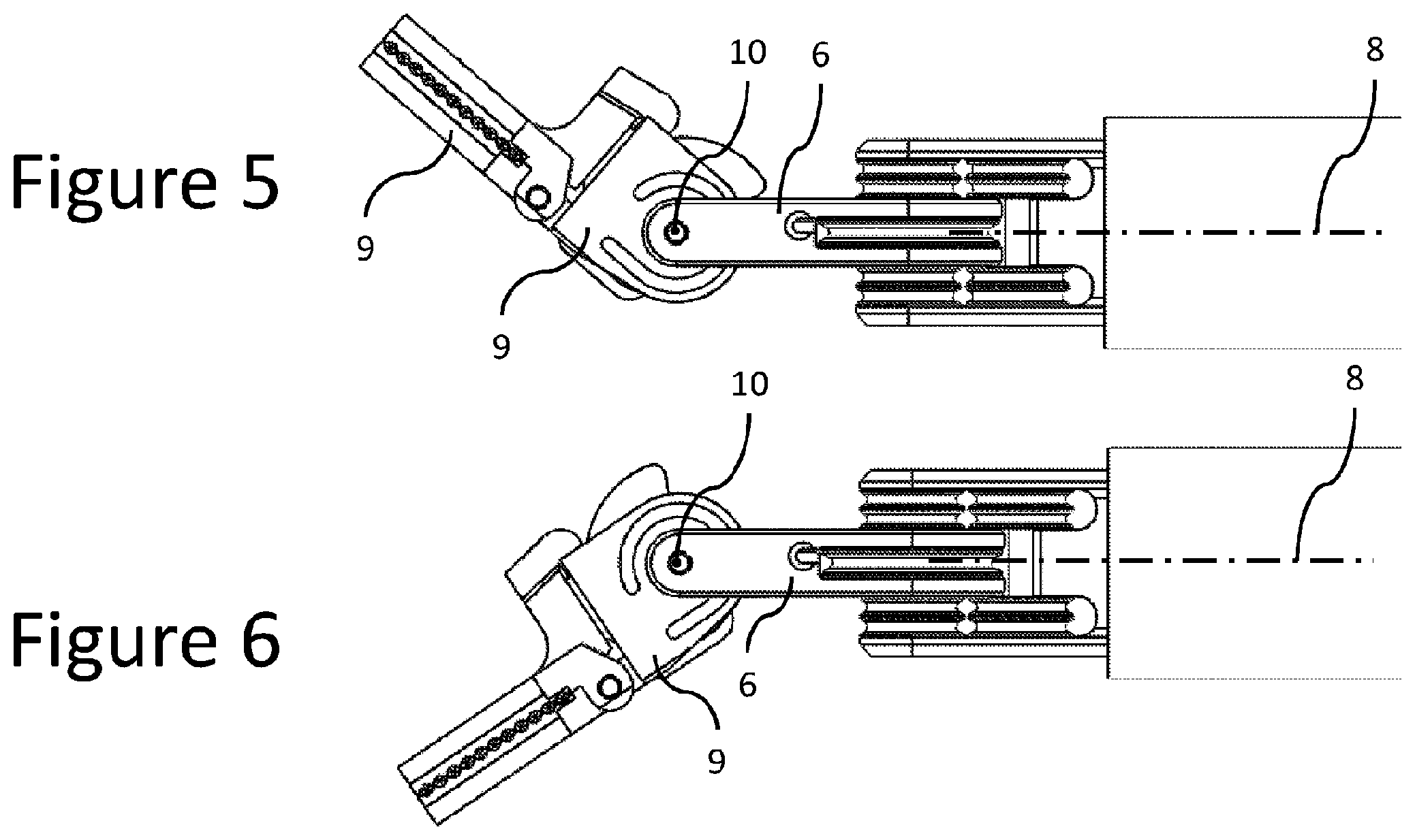
FIG. 5 shows the articulated end-effector of FIG. 2 in a third active position;
FIG. 6 shows the articulated end-effector of FIG. 2 in a fourth active position;
FIG. 7 shows the articulated end-effector of FIG. 2 in a sixth active position;
FIG. 8 shows the articulated end-effector of FIG. 2 in a seventh active position;
FIG. 9 shows a perspective view of the surgical instrument of FIG. 1 with a schematic cutout of an outer tube of the longitudinal shaft of the surgical instrument, through which is it possible to see the different flexible mechanical transmission elements;
FIG. 10 shows actuation topology for a distal end-effector link according to an embodiment of the invention;
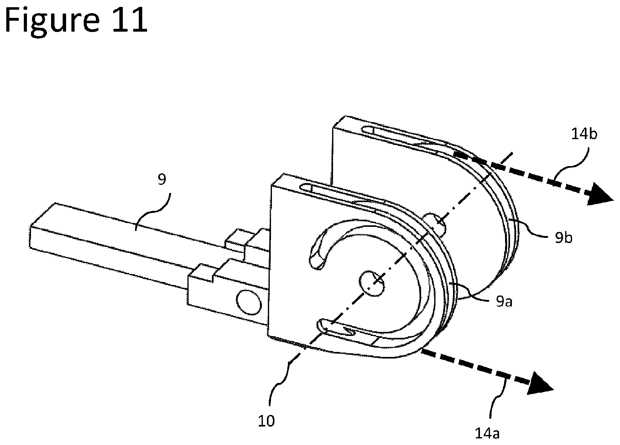
FIG. 11 shows actuation topology for a second end-effector link according to an embodiment of the invention;
FIG. 12 shows actuation topology for a cam element of a cam-and-follower mechanism according to an embodiment of the invention;
FIG. 13 shows a side view of a cam-and-follower mechanism actuating a distal articulation of an instrument's end-effector according to an embodiment of the invention;
FIG. 14 shows the cam-and-follower mechanism of FIG. 13 in a first active position;
FIG. 15 shows the cam-and-follower mechanism of FIG. 13 in a second active position;
FIG. 16 illustrates the phenomenon of force amplification of a cam-and-follower mechanism with a single-pitch spiral-profile cam element according to an embodiment of the invention;
FIG. 17 illustrates the phenomenon of force amplification of a cam-and-follower mechanism with a dual-pitch spiral-profile cam element according to an embodiment of the invention;
FIG. 18 shows a perspective view of two cam elements (reverse and actuation) rigidly attached, according to an embodiment of the invention;
FIG. 19 shows a reverse cam-and-follower mechanism in a first active position according to the embodiment shown in FIG. 18;
FIG. 20 shows a reverse cam-and-follower mechanism in a second active position according to the embodiment shown in FIG. 19;
FIGS. 21 and 22 show an embodiment of the current invention with a spring element to reverse the actuation movement, in two different working positions;
FIG. 23 shows a perspective view of a surgical instrument previously disclosed by Applicants;
FIG. 24 shows a perspective view of an articulated end-effector of the surgical instrument shown in FIG. 23;
FIG. 25 shows the actuation topology for a first distal end-effector link of the surgical instrument shown in FIG. 23;
FIG. 26 shows the actuation topology for a second distal end-effector link of the surgical instrument shown in FIG. 23;
FIG. 27 shows a perspective views of the two distal end-effector links of the surgical instrument shown in FIG. 23;
FIG. 28 shows the articulated end-effector of the surgical instrument shown in FIG. 23 achieving an actuation by the movement of the distal end-effector links;
FIG. 29 shows a free body diagram of one of the distal end-effector members of the surgical instrument shown in FIG. 23.
DETAILED DESCRIPTION OF THE INVENTION
With general reference to FIG. 1, a surgical instrument 1 for minimally invasive surgical procedures, with an articulated end-effector constructed in accordance with an embodiment of the present invention, is described herein. This instrument 1 includes a main shaft 2 with a distal end-effector 3 and a proximal extremity 4 or head. Referring to FIG. 2, the end-effector 3 is connected to the distal extremity 20 of the main shaft 2 by a proximal joint, which allows the rotation of a proximal end-effector link 6 around a proximal axis 7 in such a manner that the orientation of the proximal end-effector link 6 with respect to the main shaft axis 8 can be changed.
Referring to FIG. 2, a second end-effector link 9 is rotatably connected to the proximal end-effector link 6 by a second end-effector joint, which is represented by the second end-effector axis 10. This second end-effector axis 10 is substantially perpendicular and non-intersecting with the proximal axis 7 and substantially intersects the main shaft axis 8.
Referring to FIG. 2, the distal end-effector link 11 is rotatably connected to the second end-effector link 9 by a distal end-effector joint, which is represented by the distal end-effector axis 12. This distal end-effector axis 12 is substantially parallel to the second end-effector axis 10 and perpendicular and non-intersecting with the proximal end-effector axis 7.
By actuating the proximal joint, the proximal end-effector link 6 can be angulated over the proximal axis 7, in the range of up to .+-.90.degree., with respect to the plane containing the main shaft axis 8 and the proximal axis 7, thus providing a first orientational degree of freedom for the end effector 3. FIGS. 3 and 4 show a surgical instrument 1 according to an embodiment of the present invention with different angular displacements at the proximal joint.
By actuating the second end-effector joint, the second end-effector link 9 can be angulated, substantially up to .+-.90.degree., over the second end-effector axis 10, with respect to the plane containing the main shaft axis 8 and the second end-effector axis 10, thus providing a second orientational degree of freedom for the end effector 3 that is perpendicular to the aforementioned first orientational degree of freedom. FIGS. 5 and 6 show a surgical instrument 1 according to an embodiment of the present invention with different angular displacements at the second end-effector joint.
By actuating the distal end-effector joint, the distal end-effector link 11 can be angulated, over the distal end-effector axis 12, so that the surgical instrument is actuated in order to accomplish its function (for instance as a needle holder, scissors or forceps), thus providing an actuation degree of freedom at the end effector 3. FIGS. 7 and 8 show the surgical instrument 1 with different angular displacements at the distal end-effector joint.
With reference to FIG. 9, the main shaft 2 allows the passage of flexible elements 13, 14, 15 that are able to deliver motion to the different end-effector links 6, 9, 11, from the proximal extremity 4 or head of the instrument shaft 2. The flexible elements 13, 14, 15, may optionally take the form of metal ropes or cables which may be constructed of tungsten, steel or any other metal suitable for surgical applications.
As can be seen in FIG. 10, the flexible element 13 comprises two different segments, 13a, 13b, which form a closed cable loop between the proximal end-effector link 6 and an input element at the proximal extremity 4 of the instrument shaft 2. The proximal end-effector link 6 is operatively connected to the flexible members 13a and 13b so that it can be independently rotated in both directions along the proximal axis 7. The contact between the flexible elements 13a, 13b and the proximal end-effector link 6 is made in a grooved pulley 16, which is rigidly attached or operably connected to the proximal end-effector link 6.
As can be seen in FIG. 11, the flexible element 14 comprises two different segments, 14a, 14b, which form a closed cable loop between the proximal end-effector link 6 and an input element at the proximal extremity 4 of the instrument shaft 2. The second end-effector link 9 is operatively connected to the flexible members 14a and 14b so that it can be independently rotated in both directions along the second end-effector axis 10. The contact between the flexible elements 14a, 14b and the second end-effector link 9 is made in the grooved surfaces 9a, 9b, which have a pulley-like geometry and are part of the second end-effector link 9.
In order to increase the actuation (or gripping) force at the distal jaws 9, 11, while decreasing the tension in the flexible transmission elements, a cam-and-follower mechanism is used at the instrument's articulated end-effector 3. It comprises a cam element 17 (FIG. 12), having 2 grooved surfaces 17a, 17a, with pulley-like geometry, to which the flexible members 15a and 15b are attached, so that it can be independently rotated in both directions along the second end-effector axis 10. Rigidly attached or operably connected to these pulley-like geometries 17a, 17b (or components), a cam-profile geometry 17c (or component) is also able to rotate in both directions along the second end-effector axis 10. Another element of the cam-and-follower mechanism is the follower geometry 11a (or component), which is part of (or rigidly attached to) the distal end-effector link 11 (FIG. 13). By being in contact with the cam-profile geometry 17c of the cam element 17, the follower geometry 11a (and therefore, necessarily, the distal end-effector link 11) is driven to rotate against the second end-effector element 9 when the cam element 17 is rotating (shown in counterclockwise rotation in FIGS. 14 and 15). This movement of the distal jaws 9, 11 moving against each other corresponds to the actuation of the surgical instrument 1, wherein the actuation force can be maximized by a careful selection of the profile of the cam element 17.
In some embodiments of the current invention, by way of example but not limitation, the cam element 17 may have a spiral profile (FIG. 16), whose rotation is able to drive the movement of the follower geometry 11a or component with a force that is much higher than the tension in the flexible element 15 that is driving the rotation. As a consequence, the instrument will be able to deliver high actuation forces at the jaws, while keeping the tension in the cables at more minimal values, which increases the fatigue performance and available usage cycles of the instrument and decreases the overall friction in the system.
This aforementioned force multiplication phenomenon can be better understood with the example of the wedge analogy of FIG. 16. With reference to the above embodiment, the rotation of the spiral cam element 17 so that the point of contact with the follower geometry 11a or component is traveling from point A to point B, is equivalent to driving along a y vector a follower geometry 11a or component by moving a wedge along an x vector and having the point of contact travelling from point A to point B. The angle .alpha. of the wedge is optimally a function of the pitch of the spiral and its initial radius. The smaller the angle of the wedge, the higher the multiplication of forces, from cable tension to actuation force. Thus, variation of the wedge angle (by varying spiral pitch and initial spiral radius) can be used to ultimately control the degree of force multiplication and, consequently, the degree of reduction in cable tension.
FIG. 17 shows an alternate embodiment of the current invention, where the cam profile 17a comprises different spiral profiles (from A to C and from C to B), with different pitches p1, p2. In the same way, in other embodiments of the current invention, a wide variety of shapes and profiles can be used in the cam element 17 to drive the follower geometry 11a to move according to different movement and force patterns.
In a further alternate embodiment, and in order to reverse the movement of the jaws, a second cam-and-follower mechanism can be used. FIG. 18 shows how a reverse cam element 18 can be fixed to the actuation cam element 17 so that both cam profiles are able to rotate about the same axis 10. By being in contact with the cam element 18, the follower geometry 11b (and therefore the distal end-effector link 11) is driven to rotate away from the second end-effector element 9 when the cam element is rotating (shown rotating in a clockwise direction in FIGS. 19 and 20).
In yet another embodiment of the current invention, the reverse movement can be achieved not by a second cam-and-follower mechanism but by a spring element 19, which is able to rotate (about the axis 12) the distal end-effector link 11 back to its open position, when the cam element 17 rotates back (shown rotating clockwise in FIGS. 21 and 22) and the follower geometry 11a loses contact with the cam-profile geometry 17c of the cam element 17.
While this invention has been shown and described with reference to particular embodiments thereof, one of skill in the art will readily realise that various changes in form and details will be possible without departing from the spirit and scope of the invention as defined by the appended claims. Solely by way of example, one of skill in the art will understand that various geometries are possible for the cam-and-follower elements and that various angles are possible for the wedge element, thus impacting the force multiplication effect of the inventive system.
* * * * *
References
D00000
D00001
D00002
D00003
D00004
D00005
D00006
D00007
D00008
D00009
D00010
D00011
D00012

D00013

D00014

D00015

D00016

D00017

D00018

D00019

D00020

D00021

D00022

D00023

XML
uspto.report is an independent third-party trademark research tool that is not affiliated, endorsed, or sponsored by the United States Patent and Trademark Office (USPTO) or any other governmental organization. The information provided by uspto.report is based on publicly available data at the time of writing and is intended for informational purposes only.
While we strive to provide accurate and up-to-date information, we do not guarantee the accuracy, completeness, reliability, or suitability of the information displayed on this site. The use of this site is at your own risk. Any reliance you place on such information is therefore strictly at your own risk.
All official trademark data, including owner information, should be verified by visiting the official USPTO website at www.uspto.gov. This site is not intended to replace professional legal advice and should not be used as a substitute for consulting with a legal professional who is knowledgeable about trademark law.