Articulated hand-held instrument
Beira , et al.
U.S. patent number 10,363,055 [Application Number 15/564,194] was granted by the patent office on 2019-07-30 for articulated hand-held instrument. This patent grant is currently assigned to DistalMotion SA. The grantee listed for this patent is DistalMotion SA. Invention is credited to Ricardo Daniel Rita Beira, Michael Urs Friedrich.


View All Diagrams
| United States Patent | 10,363,055 |
| Beira , et al. | July 30, 2019 |
Articulated hand-held instrument
Abstract
An articulated hand-held medical instrument is provided. The instrument is primarily intended to be used in minimally invasive surgical procedures. The articulated instrument comprises a master-slave architecture whereby user hand movements on a proximal handle element are replicated on a distal end-effector. The proximal handle comprises a number of handle links joined by handle joints that correspond to a number of end-effector links joined by end-effector joints. The articulated hand-held medical instrument can be used in standard laparoscopic procedures in various port arrangements and through the use of standard equipment such as trocars, and movements inside the patient's body may be tracked using available endoscopic cameras.
| Inventors: | Beira; Ricardo Daniel Rita (Lausanne, CH), Friedrich; Michael Urs (Bern, CH) | ||||||||||
|---|---|---|---|---|---|---|---|---|---|---|---|
| Applicant: |
|
||||||||||
| Assignee: | DistalMotion SA (Epalinges,
CH) |
||||||||||
| Family ID: | 56289537 | ||||||||||
| Appl. No.: | 15/564,194 | ||||||||||
| Filed: | April 11, 2016 | ||||||||||
| PCT Filed: | April 11, 2016 | ||||||||||
| PCT No.: | PCT/IB2016/000542 | ||||||||||
| 371(c)(1),(2),(4) Date: | October 03, 2017 | ||||||||||
| PCT Pub. No.: | WO2016/162751 | ||||||||||
| PCT Pub. Date: | October 13, 2016 |
Prior Publication Data
| Document Identifier | Publication Date | |
|---|---|---|
| US 20180125519 A1 | May 10, 2018 | |
Related U.S. Patent Documents
| Application Number | Filing Date | Patent Number | Issue Date | ||
|---|---|---|---|---|---|
| 62280736 | Jan 20, 2016 | ||||
| 62145454 | Apr 9, 2015 | ||||
| Current U.S. Class: | 1/1 |
| Current CPC Class: | A61B 17/29 (20130101); A61B 34/71 (20160201); A61B 17/2909 (20130101); A61B 17/00234 (20130101); A61B 2090/0813 (20160201); A61B 2017/0046 (20130101); A61B 2017/291 (20130101); A61B 2017/00424 (20130101); A61B 2017/2927 (20130101); A61B 2017/00738 (20130101); A61B 2017/2948 (20130101); A61B 2017/2929 (20130101) |
| Current International Class: | A61B 17/29 (20060101); A61B 34/00 (20160101); A61B 17/00 (20060101); A61B 90/00 (20160101) |
| Field of Search: | ;606/1,130,205 |
References Cited [Referenced By]
U.S. Patent Documents
| 2764301 | September 1956 | Goertz et al. |
| 2771199 | November 1956 | Jelatis |
| 2774488 | December 1956 | Goertz |
| 2846084 | August 1958 | Goertz et al. |
| 3065863 | November 1962 | Saunders, Jr. |
| 3095096 | June 1963 | Chesley |
| 3212651 | October 1965 | Specht et al. |
| 3261480 | July 1966 | Haaker et al. |
| 3297172 | January 1967 | Haaker et al. |
| 3391801 | July 1968 | Haaker |
| 3425569 | February 1969 | Haaker |
| 4221516 | September 1980 | Haaker et al. |
| 4756655 | July 1988 | Jameson |
| 5147357 | September 1992 | Rose et al. |
| 5176352 | January 1993 | Braun |
| 5207114 | May 1993 | Salisbury et al. |
| 5209747 | May 1993 | Knoepfler |
| 5304203 | April 1994 | El-Mallawany et al. |
| 5308358 | May 1994 | Bond et al. |
| 5330502 | July 1994 | Hassler et al. |
| 5368606 | November 1994 | Marlow et al. |
| 5383888 | January 1995 | Zvenyatsky et al. |
| 5484435 | January 1996 | Fleenor et al. |
| 5599151 | February 1997 | Daum et al. |
| 5603723 | February 1997 | Aranyi et al. |
| 5631973 | May 1997 | Green |
| 5649956 | July 1997 | Jensen et al. |
| 5710870 | January 1998 | Ohm et al. |
| 5716352 | February 1998 | Viola et al. |
| 5735874 | April 1998 | Measamer et al. |
| 5784542 | July 1998 | Ohm et al. |
| 5797900 | August 1998 | Madhani et al. |
| 5810716 | September 1998 | Mukherjee et al. |
| 5810805 | September 1998 | Sutcu et al. |
| 5828813 | October 1998 | Ohm |
| 5908436 | June 1999 | Cuschieri et al. |
| 5951587 | September 1999 | Qureshi et al. |
| 5976122 | November 1999 | Madhani et al. |
| 6026701 | February 2000 | Reboulet |
| 6132368 | October 2000 | Cooper |
| 6197017 | March 2001 | Brock et al. |
| 6206903 | March 2001 | Ramans |
| 6233504 | May 2001 | Das et al. |
| 6281651 | August 2001 | Haanpaa et al. |
| 6312435 | November 2001 | Wallace et al. |
| 6331181 | December 2001 | Tierney et al. |
| 6358249 | March 2002 | Chen et al. |
| 6361534 | March 2002 | Chen et al. |
| 6364879 | April 2002 | Chen et al. |
| 6371952 | April 2002 | Madhani et al. |
| 6394998 | May 2002 | Wallace et al. |
| 6435794 | August 2002 | Springer |
| 6459926 | October 2002 | Nowlin et al. |
| 6491701 | December 2002 | Tierney et al. |
| 6554844 | April 2003 | Lee et al. |
| 6587750 | July 2003 | Gerbi et al. |
| 6594552 | July 2003 | Nowlin et al. |
| 6671581 | December 2003 | Niemeyer et al. |
| 6699177 | March 2004 | Wang et al. |
| 6786896 | September 2004 | Madhani et al. |
| 6788999 | September 2004 | Green |
| 6840938 | January 2005 | Morley et al. |
| 6850817 | February 2005 | Green |
| 6852107 | February 2005 | Wang et al. |
| 6879880 | April 2005 | Nowlin et al. |
| 6902560 | June 2005 | Morley et al. |
| 6951535 | October 2005 | Ghodoussi et al. |
| 6991627 | January 2006 | Madhani et al. |
| 6994708 | February 2006 | Manzo |
| 7048745 | May 2006 | Tierney et al. |
| 7083571 | August 2006 | Wang et al. |
| 7090637 | August 2006 | Danitz et al. |
| 7101363 | September 2006 | Nishizawa et al. |
| 7204836 | April 2007 | Wagner et al. |
| 7232440 | June 2007 | Dumbauld et al. |
| 7306597 | December 2007 | Manzo |
| 7316681 | January 2008 | Madhani et al. |
| 7338513 | March 2008 | Lee et al. |
| 7364582 | April 2008 | Lee |
| 7373219 | May 2008 | Nowlin et al. |
| 7398707 | July 2008 | Morley et al. |
| 7481824 | January 2009 | Boudreaux et al. |
| 7594912 | September 2009 | Cooper et al. |
| 7608039 | October 2009 | Todd |
| 7615002 | November 2009 | Rothweiler et al. |
| 7615067 | November 2009 | Lee et al. |
| 7674255 | March 2010 | Braun |
| 7699855 | April 2010 | Anderson et al. |
| 7756036 | July 2010 | Druke et al. |
| 7819894 | October 2010 | Mitsuishi et al. |
| 7824401 | November 2010 | Manzo et al. |
| 7828798 | November 2010 | Buysse et al. |
| 7890211 | February 2011 | Green |
| 7914521 | March 2011 | Wang et al. |
| 7976458 | July 2011 | Stefanchik et al. |
| 8048084 | November 2011 | Schneid |
| 8105320 | January 2012 | Manzo |
| 8114017 | February 2012 | Bacher |
| 8137263 | March 2012 | Marescaux et al. |
| 8142447 | March 2012 | Cooper et al. |
| 8224485 | July 2012 | Unsworth |
| 8287469 | October 2012 | Stefanchik et al. |
| 8292889 | October 2012 | Cunningham et al. |
| 8306656 | November 2012 | Schaible et al. |
| 8308738 | November 2012 | Nobis et al. |
| 8332072 | December 2012 | Schaible et al. |
| 8336751 | December 2012 | Scirica |
| 8347754 | January 2013 | Veltri et al. |
| 8353898 | January 2013 | Lutze et al. |
| 8357161 | January 2013 | Mueller |
| 8382742 | February 2013 | Hermann et al. |
| 8403832 | March 2013 | Cunningham et al. |
| 8418904 | April 2013 | Wenchell et al. |
| 8423186 | April 2013 | Itkowitz et al. |
| 8496152 | July 2013 | Viola |
| 8523900 | September 2013 | Jinno et al. |
| 8540748 | September 2013 | Murphy et al. |
| 8562592 | October 2013 | Conlon et al. |
| 8568444 | October 2013 | Cunningham |
| 8579176 | November 2013 | Smith et al. |
| 8591397 | November 2013 | Berkelman et al. |
| 8603077 | December 2013 | Cooper et al. |
| 8617203 | December 2013 | Stefanchik et al. |
| 8663270 | March 2014 | Donnigan et al. |
| 8668689 | March 2014 | Dumbauld et al. |
| 8668702 | March 2014 | Awtar et al. |
| 8696666 | April 2014 | Sanai et al. |
| 8709000 | April 2014 | Madhani et al. |
| 8761930 | June 2014 | Nixon |
| 8768509 | July 2014 | Unsworth |
| 8792688 | July 2014 | Unsworth |
| 8801752 | August 2014 | Fortier et al. |
| 8816628 | August 2014 | Nowlin et al. |
| 8818560 | August 2014 | Kishi |
| 8821480 | September 2014 | Burbank |
| 8828046 | September 2014 | Stefanchik et al. |
| 8845517 | September 2014 | Russo |
| 8845622 | September 2014 | Paik et al. |
| 8870867 | October 2014 | Walberg et al. |
| 8887979 | November 2014 | Mastri et al. |
| 8894674 | November 2014 | Balanev et al. |
| 8930027 | January 2015 | Schaible et al. |
| 8945098 | February 2015 | Seibold et al. |
| 8961499 | February 2015 | Paik et al. |
| 8961514 | February 2015 | Garrison |
| 8968187 | March 2015 | Kleyman et al. |
| 8989844 | March 2015 | Cinquin et al. |
| 8992564 | March 2015 | Jaspers |
| 9023015 | May 2015 | Penna |
| 9033998 | May 2015 | Schaible et al. |
| 9044238 | June 2015 | Orszulak |
| 9084606 | July 2015 | Greep |
| 9113861 | August 2015 | Martin et al. |
| 9149339 | October 2015 | Unsworth |
| 9307894 | April 2016 | Von Grunberg et al. |
| 9474580 | October 2016 | Hannaford et al. |
| 9480531 | November 2016 | Von Grunberg |
| 9492240 | November 2016 | Itkowitz et al. |
| 9696700 | July 2017 | Beira et al. |
| 10071488 | September 2018 | Robinson et al. |
| 10092359 | October 2018 | Beira et al. |
| 10265129 | April 2019 | Beira |
| 2002/0040217 | April 2002 | Jinno |
| 2002/0049367 | April 2002 | Irion et al. |
| 2002/0072736 | June 2002 | Tierney et al. |
| 2003/0155747 | August 2003 | Bridges |
| 2003/0208186 | November 2003 | Moreyra |
| 2004/0049205 | March 2004 | Lee et al. |
| 2004/0116906 | June 2004 | Lipow |
| 2004/0236316 | November 2004 | Danitz et al. |
| 2004/0253079 | December 2004 | Sanchez |
| 2005/0096502 | May 2005 | Khalili |
| 2005/0204851 | September 2005 | Morley et al. |
| 2005/0240078 | October 2005 | Kwon et al. |
| 2006/0043698 | March 2006 | Bridges |
| 2006/0178559 | August 2006 | Kumar et al. |
| 2006/0183975 | August 2006 | Saadat et al. |
| 2006/0219065 | October 2006 | Jinno et al. |
| 2006/0235436 | October 2006 | Anderson et al. |
| 2006/0253109 | November 2006 | Chu |
| 2007/0088340 | April 2007 | Brock et al. |
| 2007/0137371 | June 2007 | Devengenzo et al. |
| 2007/0156123 | July 2007 | Moll et al. |
| 2007/0208375 | September 2007 | Nishizawa et al. |
| 2007/0299387 | December 2007 | Williams et al. |
| 2008/0039255 | February 2008 | Jinno et al. |
| 2008/0046122 | February 2008 | Manzo et al. |
| 2008/0058776 | March 2008 | Jo et al. |
| 2008/0071208 | March 2008 | Voegele et al. |
| 2008/0103492 | May 2008 | Morley et al. |
| 2008/0177285 | July 2008 | Brock et al. |
| 2008/0243106 | October 2008 | Coe et al. |
| 2008/0314181 | December 2008 | Schena |
| 2009/0036902 | February 2009 | Dimaio et al. |
| 2009/0198253 | August 2009 | Omori |
| 2009/0216248 | August 2009 | Uenohara et al. |
| 2009/0216249 | August 2009 | Jinno et al. |
| 2009/0247821 | October 2009 | Rogers |
| 2009/0248039 | October 2009 | Cooper et al. |
| 2009/0299141 | December 2009 | Downey et al. |
| 2010/0004508 | January 2010 | Naito et al. |
| 2010/0011900 | January 2010 | Burbank |
| 2010/0023025 | January 2010 | Zeiner et al. |
| 2010/0094130 | April 2010 | Ninomiya et al. |
| 2010/0121347 | May 2010 | Jaspers |
| 2010/0160929 | June 2010 | Rogers et al. |
| 2010/0160940 | June 2010 | Lutze et al. |
| 2010/0170519 | July 2010 | Romo et al. |
| 2010/0225209 | September 2010 | Goldberg et al. |
| 2010/0305595 | December 2010 | Hermann |
| 2010/0318099 | December 2010 | Itkowitz et al. |
| 2010/0318101 | December 2010 | Choi |
| 2010/0331859 | December 2010 | Omori |
| 2011/0087236 | April 2011 | Stokes et al. |
| 2011/0087238 | April 2011 | Wang et al. |
| 2011/0213346 | September 2011 | Morley et al. |
| 2011/0230867 | September 2011 | Hirschfeld et al. |
| 2011/0275901 | November 2011 | Shelton, IV |
| 2011/0276084 | November 2011 | Shelton, IV |
| 2011/0290854 | December 2011 | Timm et al. |
| 2011/0301419 | December 2011 | Craft et al. |
| 2012/0027762 | February 2012 | Schofield |
| 2012/0031114 | February 2012 | Mueller et al. |
| 2012/0049623 | March 2012 | Nakayama |
| 2012/0095298 | April 2012 | Stefanchik et al. |
| 2012/0116163 | May 2012 | Lutze et al. |
| 2012/0132018 | May 2012 | Tang et al. |
| 2012/0143173 | June 2012 | Steege et al. |
| 2012/0158014 | June 2012 | Stefanchik et al. |
| 2012/0191245 | July 2012 | Fudaba et al. |
| 2012/0209292 | August 2012 | Devengenzo et al. |
| 2012/0253326 | October 2012 | Kleyman |
| 2012/0277762 | November 2012 | Lathrop et al. |
| 2012/0283745 | November 2012 | Goldberg et al. |
| 2012/0289973 | November 2012 | Prisco et al. |
| 2012/0289974 | November 2012 | Rogers et al. |
| 2012/0296341 | November 2012 | Seibold et al. |
| 2013/0123805 | May 2013 | Park et al. |
| 2013/0144274 | June 2013 | Stefanchik et al. |
| 2013/0172713 | July 2013 | Kirschenman |
| 2013/0245643 | September 2013 | Woodard et al. |
| 2013/0245647 | September 2013 | Martin et al. |
| 2013/0282027 | October 2013 | Woodard et al. |
| 2013/0303408 | November 2013 | Indermuhle |
| 2013/0304083 | November 2013 | Kaercher et al. |
| 2013/0304084 | November 2013 | Epfl |
| 2014/0005681 | January 2014 | Gee et al. |
| 2014/0018447 | January 2014 | McGovern et al. |
| 2014/0018780 | January 2014 | Hirscheld |
| 2014/0076088 | March 2014 | Berkelman et al. |
| 2014/0114481 | April 2014 | Ogawa et al. |
| 2014/0142595 | May 2014 | Awtar et al. |
| 2014/0166023 | June 2014 | Kishi |
| 2014/0180308 | June 2014 | Von Grunberg |
| 2014/0188091 | July 2014 | Vidal et al. |
| 2014/0188159 | July 2014 | Steege |
| 2014/0195010 | July 2014 | Epfl |
| 2014/0200561 | July 2014 | Ingmanson et al. |
| 2014/0207150 | July 2014 | Rosa et al. |
| 2014/0230595 | August 2014 | Butt et al. |
| 2014/0249546 | September 2014 | Shvartsberg et al. |
| 2014/0263541 | September 2014 | Leimbach et al. |
| 2014/0263553 | September 2014 | Leimbach et al. |
| 2014/0276950 | September 2014 | Smaby et al. |
| 2014/0276951 | September 2014 | Hourtash et al. |
| 2014/0276956 | September 2014 | Crainich et al. |
| 2014/0350570 | November 2014 | Lee |
| 2015/0057499 | February 2015 | Erden et al. |
| 2015/0057702 | February 2015 | Edmondson et al. |
| 2015/0060517 | March 2015 | Williams |
| 2015/0066018 | March 2015 | Doll et al. |
| 2015/0105821 | April 2015 | Ward et al. |
| 2015/0113933 | April 2015 | Markt |
| 2015/0142018 | May 2015 | Sniffin et al. |
| 2015/0150575 | June 2015 | Hartoumbekis et al. |
| 2015/0250547 | September 2015 | Fukushima et al. |
| 2015/0265355 | September 2015 | Prestel et al. |
| 2016/0022365 | January 2016 | Jensen et al. |
| 2016/0051274 | February 2016 | Howell et al. |
| 2016/0151115 | June 2016 | Karguth et al. |
| 2016/0346053 | December 2016 | Beira |
| 2016/0374766 | December 2016 | Schuh |
| 2017/0245954 | August 2017 | Beira |
| 2017/0273749 | September 2017 | Grover et al. |
| 2017/0308667 | October 2017 | Beira et al. |
| 2017/0360522 | December 2017 | Beira |
| 2017/0367778 | December 2017 | Beira |
| 2018/0000472 | January 2018 | Beira |
| 2018/0000544 | January 2018 | Beira |
| 2018/0000550 | January 2018 | Beira |
| 2018/0055583 | March 2018 | Schuh et al. |
| 2018/0125519 | May 2018 | Beira et al. |
| 2018/0125592 | May 2018 | Beira |
| 2018/0242991 | August 2018 | Beira |
| 2018/0353252 | December 2018 | Chassot et al. |
| 101584594 | Nov 2009 | CN | |||
| 101637402 | Feb 2010 | CN | |||
| 101732093 | Jun 2010 | CN | |||
| 103717355 | Apr 2014 | CN | |||
| 43 03 311 | Aug 1994 | DE | |||
| 19652792 | May 1999 | DE | |||
| 10314827 | Apr 2004 | DE | |||
| 10314828 | Jul 2004 | DE | |||
| 10 2012 222 755 | Jun 2014 | DE | |||
| 10 2014 205 036 | Sep 2015 | DE | |||
| 10 2014 205 159 | Sep 2015 | DE | |||
| 0 595 291 | May 1994 | EP | |||
| 0 621 009 | Oct 1994 | EP | |||
| 0 677 275 | Oct 1995 | EP | |||
| 0 776 739 | Jun 1997 | EP | |||
| 1 254 642 | Nov 2002 | EP | |||
| 1 279 371 | Dec 2004 | EP | |||
| 1 886 630 | Feb 2008 | EP | |||
| 1 889 579 | Feb 2008 | EP | |||
| 2 058 090 | May 2009 | EP | |||
| 1 977 677 | Aug 2009 | EP | |||
| 2 095 778 | Sep 2009 | EP | |||
| 1 889 583 | Apr 2011 | EP | |||
| 2 377 477 | May 2012 | EP | |||
| 2 473 119 | Jul 2012 | EP | |||
| 2 305 144 | Oct 2012 | EP | |||
| 2 044 893 | Jul 2013 | EP | |||
| 2 653 110 | Oct 2013 | EP | |||
| 2 679 192 | Jan 2014 | EP | |||
| 2 736 680 | Jun 2014 | EP | |||
| 2 777 561 | Sep 2014 | EP | |||
| 2 783 643 | Oct 2014 | EP | |||
| 2 837 340 | Feb 2015 | EP | |||
| 2 837 354 | Feb 2015 | EP | |||
| 2 554 131 | Aug 2015 | EP | |||
| 2 979 657 | Feb 2016 | EP | |||
| 0 969 899 | Sep 1964 | GB | |||
| 2004-041580 | Feb 2004 | JP | |||
| 2007-290096 | Nov 2007 | JP | |||
| 2008-104620 | May 2008 | JP | |||
| 2009-018027 | Jan 2009 | JP | |||
| 20110032444 | Mar 2011 | KR | |||
| 20130031403 | Mar 2013 | KR | |||
| WO-82/00611 | Mar 1982 | WO | |||
| WO-97/43942 | Nov 1997 | WO | |||
| WO-98/25666 | Jun 1998 | WO | |||
| WO-03/067341 | Aug 2003 | WO | |||
| WO-03/086219 | Oct 2003 | WO | |||
| WO-2004/052171 | Jun 2004 | WO | |||
| WO-2005/009482 | Feb 2005 | WO | |||
| WO-2005/046500 | May 2005 | WO | |||
| WO-2006/086663 | Apr 2006 | WO | |||
| WO-2007/133065 | Nov 2007 | WO | |||
| WO-2008/130235 | Oct 2008 | WO | |||
| WO-2009/091497 | Jul 2009 | WO | |||
| WO-2009/095893 | Aug 2009 | WO | |||
| WO-2009/145572 | Dec 2009 | WO | |||
| WO-2009/157719 | Dec 2009 | WO | |||
| WO-2010/019001 | Feb 2010 | WO | |||
| WO-2010/030114 | Mar 2010 | WO | |||
| WO-2010/050771 | May 2010 | WO | |||
| WO-2010/083480 | Jul 2010 | WO | |||
| WO-2010/096580 | Aug 2010 | WO | |||
| WO-2010/130817 | Nov 2010 | WO | |||
| WO-2011/027183 | Mar 2011 | WO | |||
| WO-2011/123669 | Oct 2011 | WO | |||
| WO-2012/020386 | Feb 2012 | WO | |||
| WO-2012/049623 | Apr 2012 | WO | |||
| WO-2013/007784 | Jan 2013 | WO | |||
| WO-2013/014621 | Jan 2013 | WO | |||
| WO-2013/014621 | Jan 2013 | WO | |||
| WO-2014/012780 | Jan 2014 | WO | |||
| WO-2014/018447 | Jan 2014 | WO | |||
| WO-2014/067804 | May 2014 | WO | |||
| WO-2014/094716 | Jun 2014 | WO | |||
| WO-2014/094717 | Jun 2014 | WO | |||
| WO-2014/094718 | Jun 2014 | WO | |||
| WO-2014/094719 | Jun 2014 | WO | |||
| WO-2014/145148 | Sep 2014 | WO | |||
| WO-2014/156221 | Oct 2014 | WO | |||
| WO-2014/201010 | Dec 2014 | WO | |||
| WO-2014/201538 | Dec 2014 | WO | |||
| WO-2015/081946 | Jun 2015 | WO | |||
| WO-2015/081947 | Jun 2015 | WO | |||
| WO-2015/088647 | Jun 2015 | WO | |||
| WO-2015/088655 | Jun 2015 | WO | |||
| WO-2015/111475 | Jul 2015 | WO | |||
| WO-2015/113933 | Aug 2015 | WO | |||
| WO-2015/129383 | Aug 2015 | WO | |||
| WO-2015/139674 | Sep 2015 | WO | |||
| WO-2015/175200 | Nov 2015 | WO | |||
| WO-2016/030767 | Mar 2016 | WO | |||
| WO-2016/083189 | Jun 2016 | WO | |||
| WO-2016/097861 | Jun 2016 | WO | |||
| WO-2016/097864 | Jun 2016 | WO | |||
| WO-2016/097868 | Jun 2016 | WO | |||
| WO-2016/097871 | Jun 2016 | WO | |||
| WO-2016/097873 | Jun 2016 | WO | |||
| WO-2016/162751 | Oct 2016 | WO | |||
| WO-2016/162752 | Oct 2016 | WO | |||
| WO-2016/183054 | Nov 2016 | WO | |||
| WO-01/6189284 | Dec 2016 | WO | |||
| WO-2016/189284 | Dec 2016 | WO | |||
| WO-2017/015599 | Jan 2017 | WO | |||
| WO-2017/064301 | Apr 2017 | WO | |||
| WO-2017/064303 | Apr 2017 | WO | |||
| WO-2017/064305 | Apr 2017 | WO | |||
| WO-2017/064306 | Apr 2017 | WO | |||
Other References
|
US. Appl. No. 13/878,924, filed May 17, 2013. cited by applicant . U.S. Appl. No. 14/233,184 / U.S. Pat. No. 9,696,700, filed Jan. 16, 2014 / Jul. 4, 2017. cited by applicant . U.S. Appl. No. 15/116,509, filed Aug. 3, 2016. cited by applicant . U.S. Appl. No. 15/506,659, filed Feb. 24, 2017. cited by applicant . U.S. Appl. No. 15/536,539, filed Jun. 15, 2017. cited by applicant . U.S. Appl. No. 15/536,562, filed Jun. 15, 2017. cited by applicant . U.S. Appl. No. 15/536,568, filed Jun. 15, 2017. cited by applicant . U.S. Appl. No. 15/536,573, filed Jun. 15, 2017. cited by applicant . U.S. Appl. No. 15/536,576, filed Jun. 15, 2017. cited by applicant . U.S. Appl. No. 15/564,193, filed Oct. 3, 2017. cited by applicant . U.S. Appl. No. 15/633,611, filed Jun. 26, 2017. cited by applicant . International Search Report & Written Opinion dated Jul. 10, 2018 in Int'l PCT Patent Appl. Serial No. PCT/IB2018/053272. cited by applicant . Abbott, et al., "Design of an Endoluminal NOTES Robotic System," IEEE/RSJ International Conference on Intelligent Robots and Systems, San Diego, CA, pp. 410-416 (2007). cited by applicant . Aesculap Surgical Technologies, Aesculap.RTM. Caiman.RTM., Advanced Bipolar Seal and Cut Technology Brochure, 6 pages (retrieved Aug. 31, 2015). cited by applicant . Arata, et al., "Development of a dexterous minimally-invasive surgical system with augmented force feedback capability," IEEE/RSJ International Conference on Intelligent Robots and Systems, pp. 3207-3212 (2005). cited by applicant . avuo{hacek over (g)}lu, et al., "Laparoscopic Telesurgical Workstation," IEEE Transactions on Robotics and Automation,(15)4:728-739 (1999). cited by applicant . Charles, et al., Dexterity-enhanced Telerobotic Microsurgery, Advanced Robotics, ICAR '97. Proceedings, 8th Int'l Conference (1997). cited by applicant . Dachs, et al., "Novel Surgical Robot Design: Minimizing the Operating Envelope Within the Sterile Field," 28th International Conference, IEEE Engineering in Medicine Biology Society, New York, pp. 1505-1508 (2006). cited by applicant . Dario, et al., "Novel Mechatronic Tool for Computer-Assisted Arthroscopy," IEEE Transactions on Information Technology in Biomedicine, 4(1):15-29 (Mar. 2000). cited by applicant . Focacci, et al., "Lightweight Hand-held Robot for Laparoscopic Surgery," IEEE International Conference on Robotics & Automation, Rome, Italy, pp. 599-604 (2007). cited by applicant . Guthart, et al., "The Intuitive.TM. Telesurgery System: Overview and Application," IEEE International Conference on Robotics & Automation, San Francisco, CA, pp. 618-621 (2000). cited by applicant . Ikuta, et al., "Development of Remote Microsurgery Robot and New Surgical Procedure for Deep and Narrow Space," IEEE International Conference on Robotics & Automation, Taipei, Taiwan, pp. 1103-1108 (2003). cited by applicant . Ikuta, et al., "Hyper Redundant Miniature Manipulator `Hyper Finger` for Remote Minimally Invasive Surgery in Deep Area," IEEE International Conference on Robotics & Automation, Taipei, Taiwan, pp. 1098-1102 (2003). cited by applicant . International Search Report & Written Opinion dated Feb. 2, 2017 in Int'l PCT Patent Appl. Serial No. PCT/IB2016/001286. cited by applicant . International Search Report & Written Opinion dated Jan. 18, 2013 in Int'l PCT Patent Appl Serial No. PCT/IB2012/053786. cited by applicant . International Search Report dated Jan. 18, 2013 in Int'l PCT Patent Appl Serial No. PCT/IB2012/053786. cited by applicant . International Search Report dated Mar. 23, 2012 in Int'l PCT Patent Appl Serial No. PCT/IB2011/054476. cited by applicant . Ishii, et al., "Development of a New Bending Mechanism and Its Application to Robotic Forceps Manipulator," IEEE International Conference on Robotics & Automation, Rome, Italy, pp. 238-243 (2007). cited by applicant . International Search Report & Written Opinion dated Feb. 17, 2016 in Int'l PCT Patent Appl Serial No. PCT/IB2015/002095. cited by applicant . International Search Report & Written Opinion dated May 23, 2016 in Int'l PCT Patent Appl Serial No. PCT/IB2015/002524. cited by applicant . International Search Report & Written Opinion dated Mar. 23, 2012 in Int'l PCT Patent Appl Serial No. PCT/IB2011/054476. cited by applicant . International Search Report & Written Opinion dated Mar. 30, 2015 in Int'l PCT Patent Appl Serial No. PCT/EP2015/051473. cited by applicant . International Search Report & Written Opinion dated Apr. 26, 2016 in Int'l PCT Patent Appl Serial No. PCT/IB2015/002512. cited by applicant . International Search Report & Written Opinion dated May 24, 2016 in Int'l PCT Patent Appl Serial No. PCT/IB2015/002487. cited by applicant . International Search Report & Written Opinion dated Jun. 10, 2016 in Int'l PCT Patent Appl Serial No. PCT/IB2015/002533. cited by applicant . International Search Report & Written Opinion dated Jun. 13, 2016 in Int'l PCT Patent Appl Serial No. PCT/IB2015/002493. cited by applicant . International Search Report & Written Opinion dated Aug. 25, 2016 in Int'l PCT Patent Appl Serial No. PCT/IB2016/000542. cited by applicant . International Search Report & Written Opinion dated Sep. 2, 2016 in Int'l PCT Patent Appl Serial No. PCT/IB2016/000543. cited by applicant . Kobayashi, et al., "Small Occupancy Robotic Mechanisms for Endoscopic Surgery," International Conference on Medical Image Computing and Computer assisted Interventions, pp. 75-82 (2002). cited by applicant . Lang, et al., Intra-operative robotics: NeuroArm., Acta Neurochir Suppl, 109:231-236 (2011). cited by applicant . Mayer, et al., "The Endo[PA]R System for Minimally Invasive Robotic Surgery," IEEE/RSJ International Conference on Intelligent Robots and Systems, Sendai, Japan, pp. 3637-3642 (2004). cited by applicant . Mitsuishi, et al., "Development of a Remote Minimally Invasive Surgical System with Operational Environment Transmission Capability," IEEE International Conference on Robotics & Automation, Taipei, Taiwan, pp. 2663-2670 (2003). cited by applicant . Mitsuishi, et al., Master-slave robotic platform and its feasibility study for micro-neurosurgery, Int. J. Med. Robot., 9(2):180-9 (2013). cited by applicant . Morita, et al., Microsurgical robotic system for the deep surgical field: development of a prototype and feasibility studies in animal and cadaveric models, J. Neurosurg., 103(2):320-7 (2005). cited by applicant . Nakamura, et al., "Multi-DOF Forceps Manipulator System for Laparoscopic Surgery-Mechanism miniaturized & Evaluation of New Interface," 4th International Conference on Medical Image Computing and Computer assisted Interventions (MICCAI2001), pp. 606-613 (2001). cited by applicant . Peirs, et al., "Design of an advanced tool guiding system for robotic surgery," IEEE International Conference on Robotics & Automation, Taipei, Taiwan, pp. 2651-2656 (2003). cited by applicant . Salle, et al., "Optimal Design of High Dexterity Modular MIS Instrument for Coronary Artery Bypass Grafting," IEEE International Conference on Robotics & Automation, New Orleans, LA, pp. 1276-1281 (2004). cited by applicant . Seibold, et al., "Prototype of Instrument for Minimally Invasive Surgery with 6-Axis Force Sensing Capability," IEEE International Conference on Robotics & Automation, Barcelona, Spain, pp. 496-501 (2005). cited by applicant . Simaan et al., "Dexterous System for Laryngeal Surgery: Multi-Backbone Bending Snake-like Slaves for Teleoperated Dexterous Surgical Tool Manipulation," IEEE International Conference on Robotics & Automation, New Orleans, LA, pp. 351-357 (2004). cited by applicant . Stryker.RTM., Endoscopy, Take a Look Around, Ideal Eyes.TM. FFD122 HD, Articulating Laparoscope Brochure, 2 pages (2009). cited by applicant . Swiss Search Report dated Jun. 4, 2012 in Swiss Patent Application No. CH 00702/12. cited by applicant . Tavakoli, et al., "Force Reflective Master-Slave System for Minimally Invasive Surgery," IEEE/RSJ International Conference on Intelligent Robots and Systems, Las Vegas, NV, pp. 3077-3082 (2003). cited by applicant . Taylor, et al., "Steady-Hand Robotic System for Microsurgical Augmentation," The International Journal of Robotics Research, 18(12):1201-1210 (1999). cited by applicant . www.cttc.co/technologies/maestro-non-robotic-dexterous-laproscopic-instrum- ent-writs-providing-seven-degrees, "Maestro: Non-Robotic Dexterous Laproscopic Instrument With a Wrist Providing Seven Degrees of Freedom", accessed Nov. 12, 2015, 4 pages. cited by applicant . Yamashita, et al., "Development of Endoscopic Forceps Manipulator Using Multi-Slider Linkage Mechanisms," The 1st Asian Symposium on Computer Aided Surgery-Robotic and Image-Guided Surgery, Ibaraki, Japan, 4 pages (2005). cited by applicant . Zeus, "Robotic Surgical System" available at http://allaboutroboticsurgery.com/zeusrobot.html. cited by applicant. |
Primary Examiner: Shi; Katherine M
Attorney, Agent or Firm: Foley & Lardner LLP Bolten; Christopher C. Pisano; Nicola A.
Parent Case Text
CROSS-REFERENCE TO RELATED APPLICATIONS
This application is a national phase of International PCT Patent Application No. PCT/IB2016/000542, filed Apr. 11, 2016, which claims priority to U.S. Provisional Patent Application Nos. 62/280,736, filed Jan. 20, 2016, and 62/145,454, filed Apr. 9, 2015, the entire contents of each of which are incorporated herein by reference.
Claims
The invention claimed is:
1. A handheld surgical instrument comprising: an instrument shaft having a proximal end and a distal end; an articulated handle; an articulated end effector connected to the distal end of the instrument shaft; a structural frame having a proximal end mounted on the articulated handle and a distal end coupled to the proximal end of the instrument shaft, the structural frame comprising three joints, each of the three joints having an axis that intersects at a remote center of motion of the handheld surgical instrument, the remote center of motion configured to be coincident to a central point of a user's wrist; and a flexible mechanical transmission system connecting the articulated handle to the articulated end effector such that motion applied to the articulated handle is reproduced at the articulated end effector, wherein the articulated end effector comprises at least three orientation or actuation degrees of freedom, and wherein the flexible mechanical transmission system follows a continuous path from a proximal end of the articulated handle to the distal end of the articulated handle and then from the proximal to the distal end of the structural frame and then from the proximal to the distal end of the instrument shaft and then from a proximal end of the articulated end-effector to a distal end of the articulated end effector.
2. The handheld surgical instrument of claim 1, wherein the flexible mechanical transmission system comprises a system of cables and pulleys disposed at the articulated handle and articulated end effector.
3. The handheld surgical instrument of claim 2, wherein the flexible mechanical transmission system comprises a closed loop configuration.
4. The handheld surgical instrument of claim 3, wherein at least one of the cables of the system of cables and pulleys runs from a driving pulley coupled to the articulated handle, through a plurality of guiding pulleys, to a driven pulley coupled to the articulated end effector.
5. The handheld surgical instrument of claim 1, wherein the handle comprises a joystick-like or pistol-grip-like shape.
6. The handheld surgical instrument of claim 1, wherein a geometry of the structural frame allows alignment of the human user's wrist with the remote center of motion of the handheld surgical instrument.
7. The handheld surgical instrument of claim 6, wherein the geometry of the structural frame allows the articulated handle a full range of movement without colliding with the instrument shaft.
8. The handheld surgical instrument of claim 1, wherein the articulated handle comprises a plurality of handle links connected by a corresponding plurality of handle joints and wherein the articulated end effector comprises a plurality of end-effector links connected by a corresponding plurality of end effector joints, and wherein the number of handle links is equal to the number of end-effector links.
9. The handheld surgical instrument of claim 1, wherein the handle comprises a scissors-like or needle-holder-like configuration.
10. The handheld surgical instrument of claim 1, wherein the at least three degrees of freedom of the articulated end effector comprise at least two orientational degrees of freedom and at least one actuation degree of freedom.
11. The handheld surgical instrument of claim 10, wherein at least two of the orientational degrees of freedom have a serial kinematic disposition.
12. The handheld surgical instrument of claim 10, wherein the at least one actuation degree of freedom is disposed in parallel to the orientational degrees of freedom.
13. The handheld surgical instrument of claim 1, wherein the flexible mechanical transmission system comprises cables made from steel or tungsten.
14. A method for performing a minimally invasive, remotely actuated surgical procedure using the handheld surgical instrument of claim 1, the method comprising: positioning the user's hand at the articulated handle such that the remote center of motion of the handheld surgical instrument is coincident with the central point of the user's wrist; laparoscopically introducing the articulated end effector into a patient to a desired location for the surgical procedure; and actuating the articulated handle such that motion applied to the articulated handle is reproduced at the articulated end effector in at least one orientation or actuation degrees of freedom via the flexible mechanical transmission system for performing the surgical procedure.
15. The method of claim 14, wherein the motion reproduced at the articulated end effector comprises a composed movement of rotation and translation.
16. The method of claim 14, wherein the at least one orientation or actuation degrees of freedom comprises at least two orientational degrees of freedom and at least one actuation degree of freedom.
17. The method of claim 14, wherein a geometry of the structural frame allows the user to articulate the articulated handle in a full range of movement without colliding with the instrument shaft.
18. A handheld surgical instrument comprising: an instrument shaft having a proximal end and a distal end; an articulated handle; an articulated end effector connected to the distal end of the instrument shaft; a structural frame having a proximal end mounted on the articulated handle and a distal end coupled to the proximal end of the instrument shaft, the structural frame comprising three joints, each of the three joints having an axis that intersects at a remote center of motion of the handheld surgical instrument, the remote center of motion configured to be coincident to a central point of a user's wrist; and a flexible mechanical transmission system connecting the articulated handle to the articulated end effector such that motion applied to the articulated handle is reproduced at the articulated end effector, wherein the articulated end effector comprises at least three orientation or actuation degrees of freedom, and wherein the articulated handle comprises a plurality of handle links connected by a corresponding plurality of handle joints and wherein the articulated end effector comprises a plurality of end-effector links connected by a corresponding plurality of end effector joints, and wherein the number of handle links is equal to the number of end-effector links.
19. The handheld surgical instrument of claim 18, wherein motion applied to a particular handle link is reproduced at the corresponding end-effector link.
20. A handheld surgical instrument comprising: an instrument shaft having a proximal end and a distal end; an articulated handle; an articulated end effector connected to the distal end of the instrument shaft; a structural frame having a proximal end mounted on the articulated handle and a distal end coupled to the proximal end of the instrument shaft, the structural frame comprising three joints, each of the three joints having an axis that intersects at a remote center of motion of the handheld surgical instrument, the remote center of motion configured to be coincident to a central point of a user's wrist; and a flexible mechanical transmission system connecting the articulated handle to the articulated end effector such that motion applied to the articulated handle is reproduced at the articulated end effector, wherein the articulated end effector comprises at least three orientation or actuation degrees of freedom, wherein the flexible mechanical transmission system comprises a system of cables and pulleys disposed at the articulated handle and articulated end effector and the flexible mechanical transmission system comprises a closed loop configuration, and wherein at least one of the cables of the system of cables and pulleys runs from a driving pulley coupled to the articulated handle, through a plurality of guiding pulleys, to a driven pulley coupled to the articulated end effector.
Description
FIELD OF THE INVENTION
The present invention relates to the field of remotely actuated mechanical systems, more particularly to surgical instruments, and most particularly to articulated hand-held surgical instruments. More specifically, this invention relates to articulated hand-held surgical instruments primarily designed to be used in minimally invasive surgical procedures. The inventive surgical instruments are designed to be used in a full range of minimally invasive surgical procedures and with standard equipment, such as trocars and endoscopic cameras. The articulated hand-held surgical instruments are designed to provide greater reach, range of motion and dexterity than that accessible with the use of standard laparoscopic instruments.
BACKGROUND OF THE INVENTION
Open surgery is still the standard technique for most surgical procedures. It has been used by the medical community for several decades and consists of performing the surgical tasks through a long incision in the abdomen, through which traditional surgical tools are inserted. However, due to the long incision, this approach is extremely invasive for the patients, resulting in substantial blood loss during the surgery and long and painful recovery periods at the hospital.
In order to reduce the invasiveness of open surgery, laparoscopy, a minimally invasive technique, was developed. Instead of a single long incision, four to five small incisions are made in the patient through which appropriately sized surgical instruments and endoscopic cameras are inserted. Because of the low invasiveness, this technique reduces blood loss and shortens hospital stays and pain. When performed by experienced surgeons, this technique can attain clinical outcomes similar to open surgery. However, despite the above-mentioned advantages, laparoscopy requires extremely advanced surgical skills to manipulate the rigid and long instrumentation. The entry incision acts as a point of rotation, decreasing the surgeon's freedom for positioning and orientating the instruments inside the patient. The movements of the surgeon's hand about this incision are inverted and scaled-up relative to the instrument tip ("fulcrum effect"), which removes dexterity, sensibility and magnifies the tremors of the surgeon's hands. In addition, these long and straight instruments force surgeons to work in a uncomfortable posture, which can be tremendously tiring during several hours of operation and result in stress and discomfort for hands, arms and body. Therefore, due to these drawbacks of laparoscopic instrumentation, these minimally invasive techniques are mainly limited to use in simple surgeries, while only a small minority of surgeons is able to use them in complex procedures.
To overcome these limitations, surgical robotic systems were developed to provide an easier-to-use approach to complex minimally invasive surgeries. By means of a computerized robotic interface, these systems enable the performance of remote laparoscopy wherein the surgeon sits at a console manipulating two master manipulators to perform the operation through several small incisions. Like laparoscopy, the robotic approach is also minimally invasive, bringing several advantages over open surgery in terms of pain, blood loss, and recovery time. In addition, it also offers better ergonomy for the surgeon compared to open and laparoscopic techniques. However, although being technically easier, robotic surgery brings several negative aspects. A major disadvantage of these systems is related to the extremely high complexity of existing robotic devices, which are composed of complex mechanical and electronic systems, leading to huge costs of acquisition and maintenance, which are not affordable for the majority of surgical departments worldwide. Another drawback of these systems comes from the fact that current surgical robots are very large, competing for precious space within the operating room environment and significantly increasing preparation time. Access to the patient is thus impaired, which, together with a lack of force-feedback, raises safety concerns.
In addition to robotic systems, several hand-held laparoscopic instruments are known. These instruments provide access to the surgical field without the need for an expensive and cumbersome robotic system, but they often provide poor ergonomy to the user.
There are known examples of hand-held, articulated surgical instruments. However, they present significant drawbacks in their designs. For example, one known articulated instrument (ref) must be attached to the user's forearm by a frame, making its use cumbersome and likely tiring, given that every movement must involve the user moving his entire forearm, which needs to be geometrically aligned with the instrument's shaft. Other known articulated instruments (refs) require the manipulation of knobs or similar elements on the device handle to produce corresponding movements in an end-effector. Such arrangement does not allow for a natural replication of user hand movements.
Accordingly, an aim of the present invention is to provide an articulated hand-held medical instrument that allows for a natural replication of user hand movements on the instrument handle at an end effector. The instrument is to allow for good ergonomy and ease of use as compared to known hand-held articulated instruments.
SUMMARY OF THE INVENTION
Theses aims and other advantages are achieved by a new articulated hand-held medical instrument. The articulated hand-held medical instrument of the present invention is primarily intended to be used in minimally invasive surgical procedures.
The articulated hand-held medical instrument comprises a frame, a proximal handle and a distal end-effector. The proximal handle is joined to the distal end-effector by an instrument tube and a structural frame. The instrument tube may optionally be introduced to the patient's body during a minimally invasive surgical procedure through a trocar or other standard piece of equipment.
The proximal handle of the articulated hand-held surgical instrument is made up of a series of handle links connected by handle joints. The distal end-effector element is generally made up of a number of end-effector links connected by end-effector joints. Mechanical transmission means transmit user motions performed on the proximal handle to the distal end-effector. In this way, the articulated hand-held surgical instrument has a master-slave architecture allowing for the replication of user hand movements on the proximal handle at the distal end-effector. Taken in conjunction with the multiple links and degrees of freedom, this architecture allows for greater dexterity and ergonomy than that accessible with standard laparoscopic instruments.
BRIEF DESCRIPTION OF FIGURES
The invention will be better understood according to the following detailed description of several embodiments with reference to the attached drawings, in which:
FIG. 1 shows a perspective view of the articulated instrument according to an embodiment of the present invention.
FIG. 2 shows a detailed perspective view of the articulated instrument according to an embodiment of the present invention;
FIG. 3 shows a detailed side view of the articulated instrument according to an embodiment of the present invention;
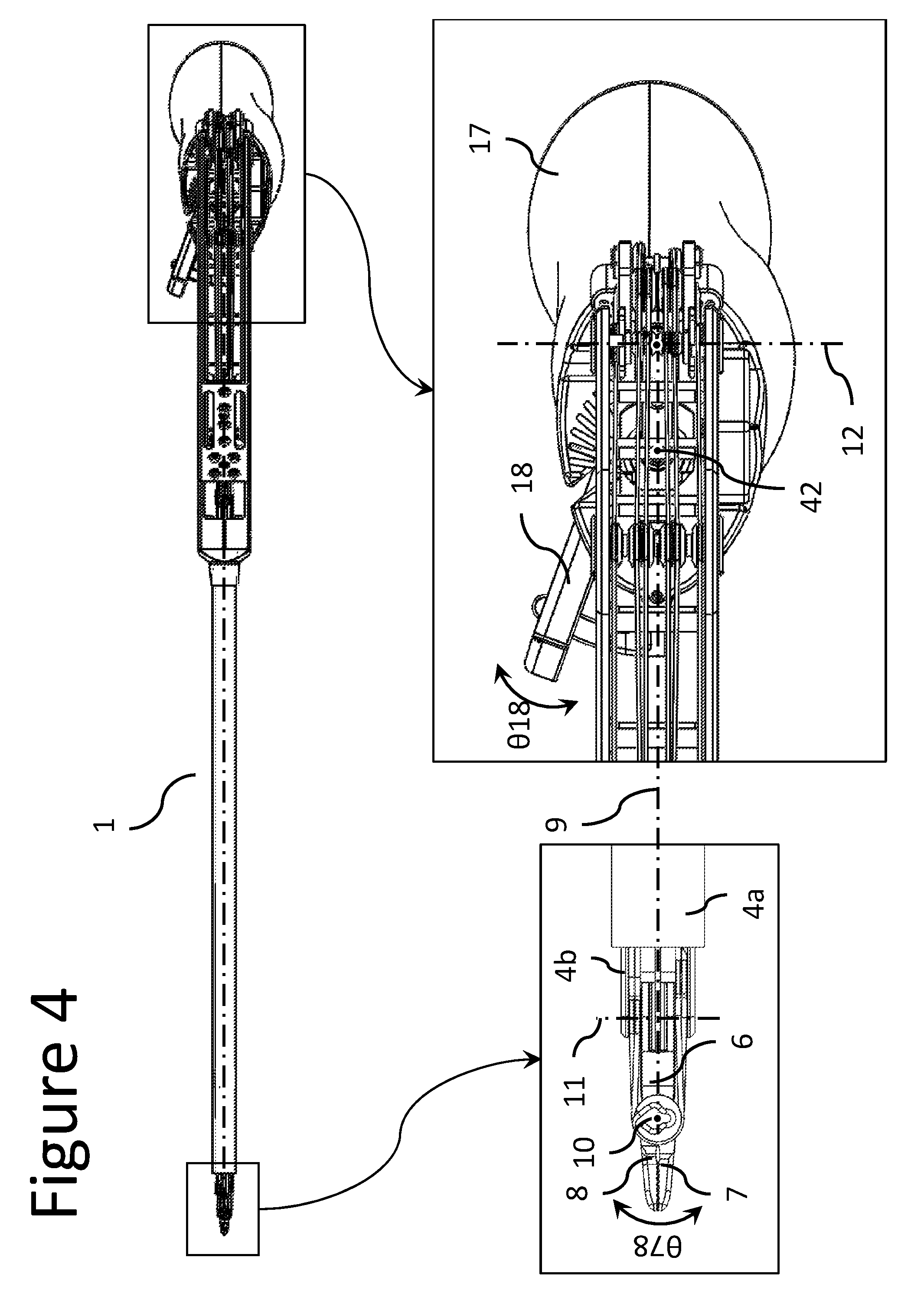
FIG. 4 shows a detailed top view of the articulated instrument according to an embodiment of the present invention;
FIG. 5 shows the distal end-effector of the articulated instrument according to an embodiment of the present invention in a first active position;
FIG. 6 shows the distal end-effector of the articulated instrument according to an embodiment of the present invention in a second active position;
FIG. 7 shows the distal end-effector of the articulated instrument according to an embodiment of the present invention in a third active position;
FIG. 8 shows the distal end-effector of the articulated instrument according to an embodiment of the present invention in a fourth active position;
FIG. 9 shows the distal end-effector of the articulated instrument according to an embodiment of the present invention in a fifth active position;
FIG. 10 shows a simplified path of a flexible transmission system actuating a distal end-effector articulation of the articulated instrument according to an embodiment of the present invention;
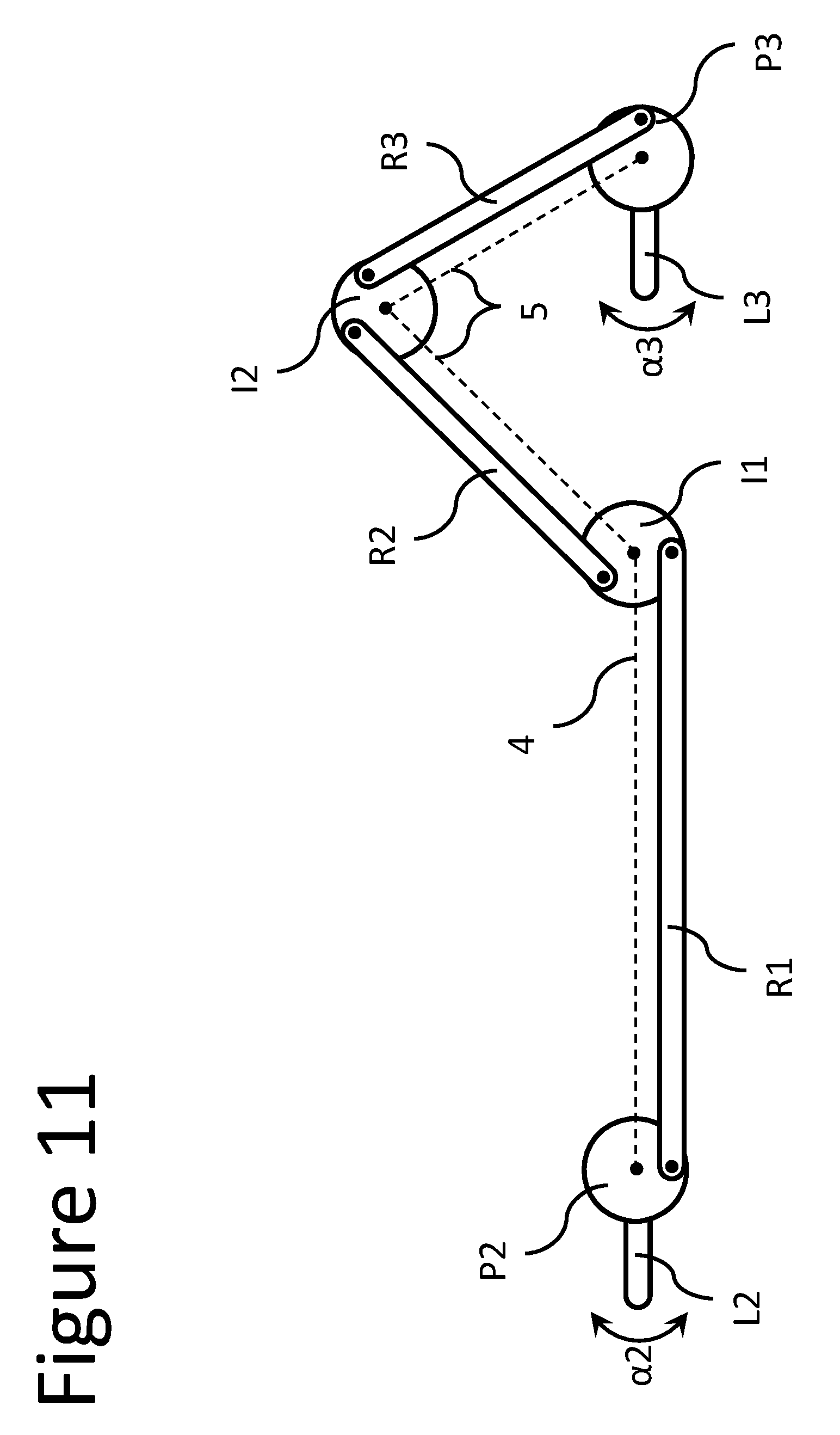
FIG. 11 shows a simplified path of a rigid transmission system actuating a distal end-effector articulation of the articulated instrument according to a different embodiment of the present invention;
FIG. 12 shows the articulated instrument according to an embodiment of the present invention in a first active position;
FIG. 13 shows the articulated instrument according to an embodiment of the present invention in a second active position;
FIG. 14 shows the articulated instrument according to an embodiment of the present invention in a third active position;
FIG. 15 illustrates the actuation of the two distal end-effector links of the articulated instrument according to an embodiment of the present invention;
FIG. 16 shows a schematic side view of the articulated instrument, according to an embodiment of the current invention;
FIG. 17 shows a perspective view of a clamp system used in the proximal handle of the articulated instrument, according to an embodiment of the current invention;
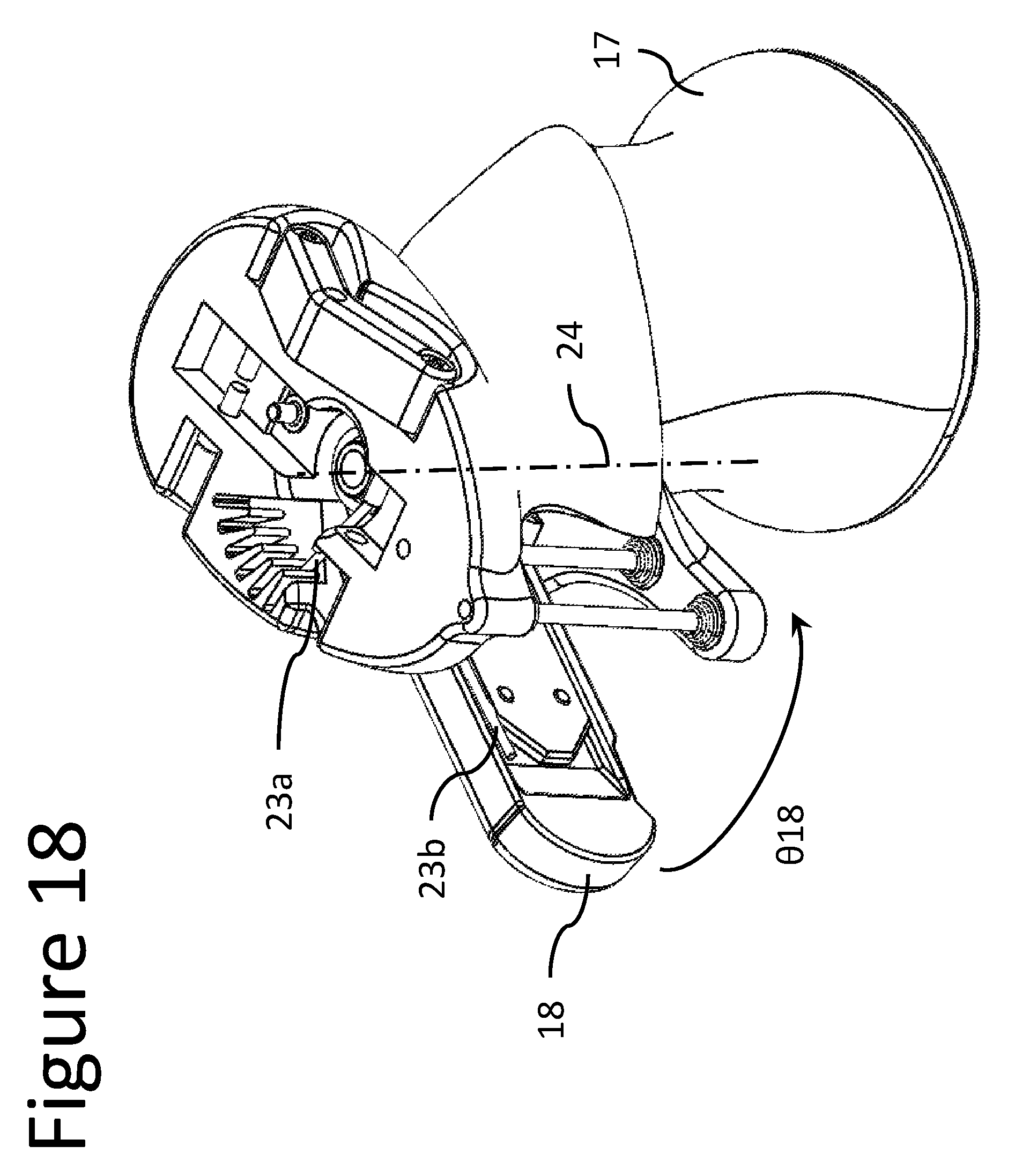
FIG. 18 shows a perspective view of a spring system used in the proximal handle of the articulated instrument, according to an embodiment of the current invention;
FIG. 19 shows a procedure through which an external tube of an instrument shaft can be assembled and disassembled on the articulated instrument according to an embodiment of the present invention;
FIG. 20 shows a distal part of an articulated instrument detached from the proximal part of the articulated instrument according to an embodiment of the present invention;
FIG. 21 shows a distal part of an articulated instrument detached from the proximal part of the articulated instrument according to another embodiment of the present invention;
FIG. 22 shows a detachable distal part of an articulated instrument according to an embodiment of the present invention;
FIG. 23 shows the rotational elements of an interface portion of a distal part of the articulated instrument according to an embodiment of the present invention;
FIG. 24 shows the rotational kinematics of an interface portion of a distal part of the articulated instrument according to an embodiment of the present invention;
FIG. 25 shows schematically the sterile interface between the distal and proximal parts of the articulated instrument according to an embodiment of the current invention;
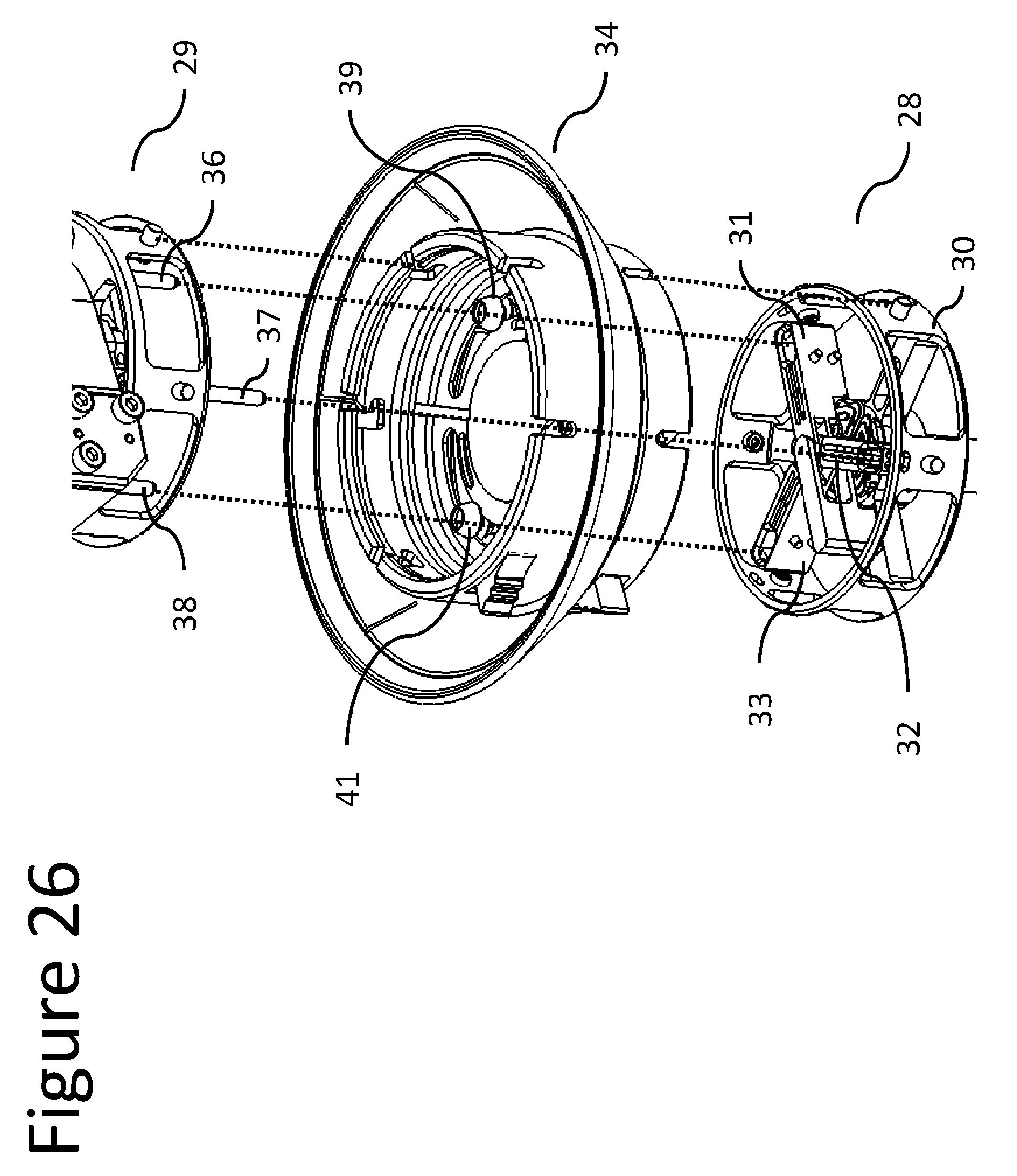
FIG. 26 shows a perspective view of a rigid connector composing a sterile interface operationally mounted between the distal and proximal parts of the articulated instrument according to an embodiment of the current invention;
FIG. 27 illustrates the actuation of the two distal end-effector links of the articulated instrument according to an embodiment of the present invention;
FIG. 28 shows an alternative kinematics of the articulated instrument according to an embodiment of the present invention;
FIG. 29 shows an alternative kinematics of the articulated instrument according to an embodiment of the present invention;
FIG. 30 shows an alternative kinematics of the articulated instrument according to an embodiment of the present invention;
FIG. 31 shows an alternative kinematics of the articulated instrument according to an embodiment of the present invention.
FIG. 32 shows a kinematic model of an embodiment of the present invention displaying the position of the user's wrist joint relative to that of a centre of rotation of the handle.
FIGS. 33 and 34 show alternative kinematic models of embodiments of the present invention displaying alignment of the user's wrist joint relative to the centre of rotation of the handle.
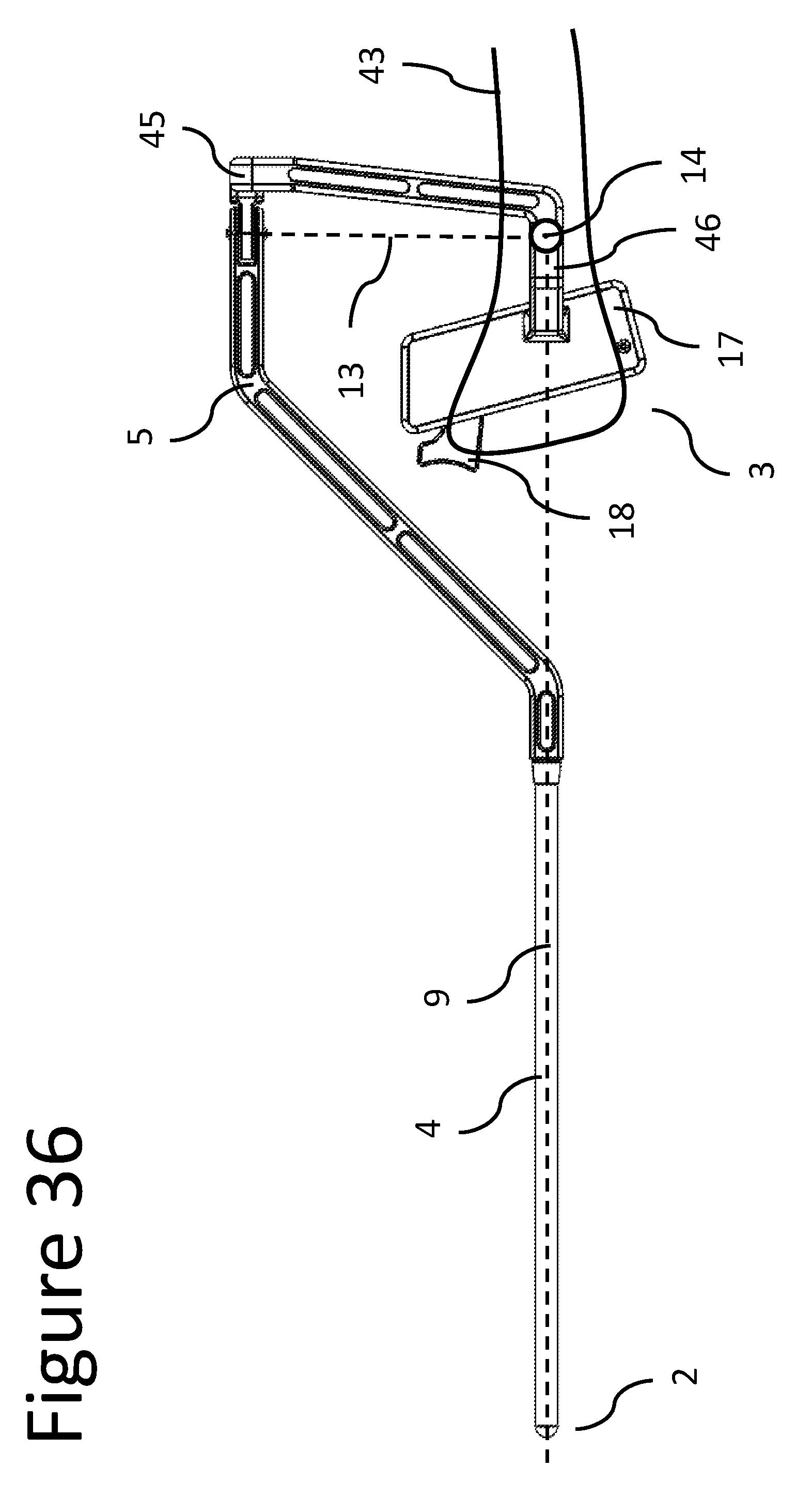
FIGS. 35, 36 and 37 show embodiments of the present invention where the user's wrist is in alignment with the centre of rotation of the handle.
FIGS. 38 and 39 show kinematic models of embodiments of the present invention including a wrist alignment concept in accordance with the invention.
FIGS. 40 and 41 show representative handle links that may be used in accordance with embodiments of the present invention.
FIG. 42 shows a schematic view of a cable rooting method to maintain a closed loop with a constant length, shown at the joint level, in accordance with various embodiments of the present invention;
FIG. 43 shows a schematic view of another cable rooting method to maintain a closed loop with a constant length, shown at the level of equivalent handle/end-effector joints, in accordance with various embodiments of the present invention;
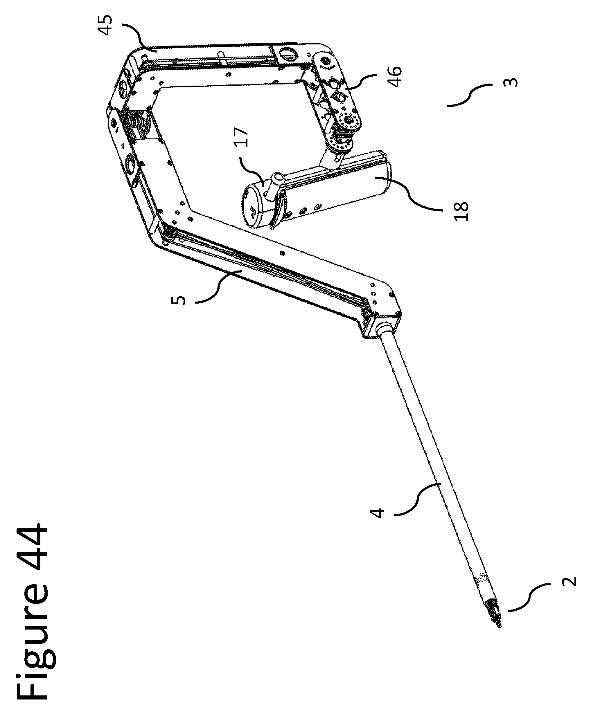
FIGS. 44, 45 and 46 show different views, with main dimensions, of a detailed design of an embodiment of the present invention.
FIGS. 47, 48 and 49 show the mechanical transmission elements of the different degrees-of-freedom of the instrument, in accordance with various embodiments of the present invention.
FIGS. 50 and 51 show detailed views of the instrument's actuation system, in accordance with various embodiments of the present invention.
DETAILED DESCRIPTION OF THE INVENTION
The articulated instrument 1 of FIG. 1, according to an embodiment of the present invention, is intended to be used in minimally invasive surgical procedures.
One of the key features of this type of articulated instrument 1 lies in its master-slave architecture, which enables the replication of the user hand movements, on a proximal handle 3 (the master), by a distal end-effector 2 (the slave) inside the patient's body.
According to FIGS. 1, 2, 3 and 4, the articulated instrument 1 comprises: i) a proximal handle 3 having a number of handle links 15, 17, 18 interconnected by a plurality of handle joints, represented by rotations over the axes 12, 13, 42; a ii) a frame 5, structurally connecting the proximal handle 3 to the distal portion of the articulated instrument 1; iii) a distal end-effector 2 having a number of end-effector links 6, 7, 8 interconnected by a plurality of end-effector joints, corresponding to the handle links, and represented by rotations over the axes 11 and 10; and iv) an instrument shaft 4, connecting the distal end of the frame 5 to the distal end-effector 2. More particularly, the kinematic chain formed by the plurality of articulated end-effector links 6, 7, 8 and corresponding end-effector joints 11, 10 of the end-effector 2, may be substantially identical to the kinematic chain formed by the plurality of articulated handle links 15, 17, 18 and corresponding handle joints 12, 13, 42 of the proximal handle 3. As can be seen in FIG. 2, in some embodiments of the present invention, the axes 9, 12, and 13 are perpendicular to each other and intersection at a central rotation point 14, which is kinematically equivalent to a spherical joint.
Referring to FIGS. 2, 3 and 4, the end-effector 2 is connected to the distal extremity of the instrument shaft 4 by a proximal end-effector joint, which allows the rotation of the proximal end-effector link 6 by the proximal axis 11 in such a manner that the orientation of the proximal end-effector link 6 with respect to the main axis 9 of the instrument shaft 4 can be changed. The distal end-effector links 7, 8 are pivotally connected to the proximal end-effector link 6 by two distal joints, having coincident axes of rotation, which are represented by the distal axis 10. This distal axis 10 is substantially perpendicular and non-intersecting with the proximal axis 11 and substantially intersects the main axis 9 of the instrument shaft 9. FIGS. 5 to 7 show the end-effector 2 with different angular displacements at the proximal end-effector link 6.
By actuating the two distal joints, the two distal end-effector links 7, 8 can be angulated over the distal axis 10, with respect to the plane containing the main axis 9 and the distal axis 10, by the angles .theta.7, .theta.8. Consequently, through the combination of rotations .theta.7 and .theta.8, it is possible to operate the surgical instrument 1, in such a manner as to provide orientation motions between the end effector and the instrument shaft 4 (FIG. 8) and to accomplish its "open/close" function (FIG. 9).
The articulated instrument 1 further comprises mechanical transmission systems arranged to kinematically connect the distal end-effector 2 with the proximal handle 3 such that the movement (angle of joint) applied on each handle joint of the proximal handle 3 is reproduced by the corresponding end-effector joint of the distal end-effector 2.
For each degree of freedom of the articulated instrument 1, different types of mechanical transmission can be used. In order to minimize the system's overall friction and inertia, certain embodiments of the current invention may use a mechanical transmission in the form of pulley-routed flexible elements, where each driven pulley of the distal end-effector 2 is connected to the respective driving pulley of the proximal handle 2, by a closed cable loop transmission. As can be seen in FIG. 10, the action of the user creating a rotation .alpha.3 on a general handle link L3 produces a rotation .alpha.3 on the handle pulley P3, which is directly connected to the handle link L3. Then, the mechanical transmission system, composed by the closed cable loop comprising cables C1 and C2, passes by the frame 5 and the instrument shaft 4 and is able to kinematically connect the handle pulley P3 to the end-effector pulley P2 (a system of idle pulleys I1, I2 is used to guide the cables C1, C2 on their path). As a result, the user actuation .alpha.3 on the handle link L3 is reproduced by the rotation .alpha.2 of the handle link L2. Depending of the use of amplification elements, .alpha.2 may be smaller, bigger or the same as .alpha.3.
The transmission of the movement between each handle pulley and the corresponding end-effector pulley in the aforementioned embodiments, by using this kind of mechanical transmission, may present certain drawbacks pertaining to kinematic and dynamic coupling between the driven and the driving pulleys. Furthermore, the adoption of a closed loop cable transmission requires that the overall length of the cable route must be kept constant, for all possible handle/end-effector configurations, independently of the motion performed by the driving pulleys of the articulated handle 2. In this sense, the aforementioned embodiments of the present invention will be operational but may not accommodate all possible use cases.
Therefore, cables must be routed through joint idler pulleys while maintaining constant cable length. The basics of the cable routing method used in this invention is illustrated in FIG. 42 for the general case of having both cables La and Lb, composing the closed loop L, being routed through a general pivot joint. The cables La and Lb are wrapped around a set of pulleys, Im, called the "joint idler pulleys," which are concentric with the joint's axis of rotation. To maintain constant cable length of the closed loop, cables La, Lb must remain in contact with the joint idler pulleys at all times. In this way, if the joint angle .theta.j is reduced, the length of the superior segment of La, in contact with the idler pulley Im will decrease and the inferior segment of Lb will increase, by the same value, guaranteeing the constant length of the cable closed loop. In addition, in order to keep a permanent contact between the cables La and Lb with the idler pulleys Im, auxiliary pulleys Ap and Ad may be added.
Another solution to keep a constant cable length of the closed loop consists in compensating the length change not at the joint level but between the equivalent idler pulleys Im and Is of respective handle and end-effector as schematically shown in FIG. 43. In this case, both cables La, Lb are passing under Im and Is and, when the joint angle .theta.j, .theta.'j, is changed, the constant length of the closed loop is guaranteed because the increase/reduction of .theta.s is compensated by the reduction/increase of .theta.m.
In a different embodiment, as is conceptually illustrated in FIG. 11, the mechanical transmission may comprise rigid elements R1, R2, R3, instead of flexible elements C1, C2, to transmit motion between the handle link L3 and the end-effector link L2. Other embodiments can be achieved by combining flexible elements with rigid elements and/or geared components.
FIGS. 12 to 14 show the articulated instrument 1 with different angular displacements at the proximal handle link 15 (and therefore, proximal end-effector link 6). The geometry of frame 5 allows for the movement of the handle 3 in its full range of motion.
In the preferred embodiment of the current invention, the actuation .theta.18 of the handle link 18 is able to produce simultaneous rotations .theta.7, .theta.8 on both the end-effector links 7, 8, with a certain movement amplification ratio. However, as shown in FIG. 15, a second distal handle link 18' may exist, so that its actuation .theta.18' can actuate the end-effector link 7 by a rotation .theta.7 and the actuation .theta.18 of the handle link 18 is actuating uniquely the end-effector link 8 by a rotation .theta.8.
In a different embodiment of the current invention, as shown in FIG. 27, the axis 42, around which the handle link 18 is able to rotate .theta.18 might be not parallel to the axis 10 around which the distal end-effector links 7, 8 are moving .theta.7, .theta.8, providing a different ergonomic position to the user. FIGS. 28 to 31 show alternative kinematics of the articulated instrument 1 according to different embodiments of the present invention.
In another embodiment of the current invention, the handle link 18 may be replaced by another handle link 19, whose axis of rotation 20 is perpendicular and non-intersecting with the axis 13 (FIG. 16), providing a different ergonomy to the user.
As can be seen in FIG. 17, a clamp element 21 may be used on the handle 3 in order to block the movement of the handle link 18 when it is brought to the "closed" position. This is particularly useful when the end-effector comprises a needle holder instrument and the user wants to apply high and constant gripping forces on needles when performing suturing tasks. Therefore, when the handle link 18 is brought .theta.18 to its "closed" position, its movement is blocked by a wedge/step geometry 21a (actuated by a system of miniature springs 22) of the clamp element 21 (FIG. 17). Then, in order to unlock the movement of the handle link 18, the user should press the clamp element 21 downwards, so that the handle link 18 can pass back through the wedge/step geometry 21a of the clamp element 21.
In another embodiment, the handle 3 may be provided with a spring element 23 that can bring the handle link 18 to an "opened" default position (FIG. 18) and apply a resistance torque when the handle link 18 is moving towards a "closing" direction.
As can be seen in FIG. 19, the external tube 4a, composing the instrument shaft 4, can be easily and individually detached and attached to the articulated instrument 1 after each procedure. Referring to FIG. 19, the internal structural element 4b is fixed directly to the frame 5 and the external tube 4a can be connected and disconnected from the internal structural element 4b by threaded surfaces or any other attachment mechanism. Therefore, with this architecture, the external tube 4a can be removed from the articulated instrument 1, without the need to disassemble other parts of the system, like the articulated end-effector 2 or the mechanical transmission elements 25, which remain completely operational without the external tube 4a. This feature facilitates tremendously the procedure to effectively clean and sterilize the articulated instrument 1, which can easily be performed by the hospital staff.
Towards a more distal region of the instrument shaft 4, the external tube 4a is in contact with a sealing element 24, which fills the gap between the internal surface of the external tube 4a and the internal structural element 4b. This sealing element 24 has little channels through which the transmission elements 25 can pass, guaranteeing the air-tightness of the articulated instrument 1.
In order to farther facilitate the cleaning and sterilization procedure, the distal part of the articulated instrument 1 may be able to be easily attached and detached to the proximal part of the articulated instrument 1. In one possible embodiment of the current invention, the attachment/detachment between the distal 26 and the proximal 27 parts of the articulated instrument 1 can be done between the frame 5 and the handle 3 (FIG. 20). However, in another embodiment of the current invention, the attachment/detachment between the distal 28 and the proximal 29 parts of the articulated instrument 1 can be done between the instrument shaft 4 and the frame 5 (FIG. 21).
In the above mentioned embodiment, the detachable distal instrument 28 may be provided with a distal articulated end-effector 2, a proximal hub 30 and the instrument shaft 4, through which different mechanical elements 25 may pass, delivering motion to the different end-effector links 6, 7, 8 (FIG. 22) from the proximal hub 30.
With reference to FIGS. 23 and 24, the movement is transmitted to each one of the three distal articulations of the articulated instrument 1 by a rotating element 31, 32, 33, which is able to rotate about the axis 9 and is connected to one of the transmission elements 25. As a result, when the rotating element 31, 32, 33 rotates a certain angle .theta.1, .theta.2, .theta.3 about the axis 9, a rotation .alpha.1, .alpha.2, .alpha.3 is transmitted to the respective end-effector link 6, 7, 8.
Since the distal part 28 of the surgical instrument 1 is partially entering the patient's body, it has to be sterile, just like the area in the vicinity of the patient. On the other hand, the proximal part 29 of the articulated instrument 1 may not be sterile and therefore should be separated from the sterile instrument portions 28 by a sterile interface 43 which protects the sterile area from the non-sterile components 29 of the articulated instrument 1 (FIG. 25).
The sterile interface 43 comprises two main components: a flexible sleeve 35, which covers the moving links of the proximal part 29 of the articulated instrument 1 and a rigid connector 35, which i) guarantees that the sterile distal part 28 of the articulated instrument 1 is not directly touching the non-sterile components of the proximal part 29, ii) enables attachment/detachment between the distal 28 and the proximal 29 parts of the articulated instrument 1, and iii) ensures the connection/disconnection of the mechanical transmission systems that deliver motion to the end-effector links 6, 7, 8.
FIG. 26 shows how the rigid connector 34 can be disposed and operationally mounted between the proximal hub 30 and the proximal part 29 of the articulated instrument 1. In order to connect/disconnect the mechanical transmission systems that deliver motion to the end-effector links 6, 7, 8, three cylindrical elements 36, 37, 38, from the proximal part 29 of the articulated instrument 1, are inserted on three miniature cups 39, 40, 41 of the rigid connector 34, which are then inserted on the rotating elements 31, 32, 33. In this way, it can be guaranteed that the sterile surgical instrument 28 is not directly touching non-sterile components.
In other embodiments of the current invention, the movement of some of the three cylindrical elements 36, 37, 38, from the proximal part 29 of the articulated instrument 1, may be constrained so that some degrees-of-freedom of the end-effector 2 can be locked/unlocked in their range of movement, allowing for instance the use of the articulated instrument 1 as a standard laparoscopic instrument, with a single degree-of-freedom at the end-effector.
The articulated hand-held medical instrument of the present invention is designed to be used in a full range of minimally invasive surgical procedures in combination with standard laparoscopic equipment. For example, the inventive instrument may optionally be inserted through a trocar and its movements inside the patient's body may be tracked with an available endoscopic camera. In addition, the articulated hand-held medical instrument may be used in a range of port arrangements in minimally invasive surgical procedures.
The articulated instrument 1 can assume other kinematics, like the kinematic models shown in FIGS. 28 to 31.
As illustrated in FIG. 32, in most of the embodiments (and kinematic models) described up to this point, the central rotation point 14 of the articulated handle 3 is not coincident with the central wrist point 43 of the user 44. However, these positional offsets .DELTA.x, .DELTA.y (and possibly .DELTA.z) can create positional mismatches (also known as "parasitic movements") between the movements applied to the handle 3 and the movements generated at the end-effector 2. In particular, a pure rotation performed by the user's hand at the handle 3 might create a composed movement, of rotation plus a translation, of the end-effector 2. Therefore, in order to compensate for that, the central rotation point 14 and the central wrist point 43 have to be aligned. In order to achieve this, other kinematic models (like the ones of FIGS. 33, 38 and 39) can be used on the articulated instrument 1 of the current invention so that the central rotation point 14 is located in the free space and not within the structure of the moving links 5, 45, 46 (this kinematic feature may also be designated by Remote Center of Motion, RCM). In some of these embodiments, like the one of FIGS. 35, 36 and 37, there are three revolute joints whose axes 9, 12, 13 intersect at the RCM. Thus, the kinematics of the articulated instrument 1 can be set so that the central rotation point 14 (or RCM) is substantially coincident to the central wrist point 44 of the user 43. FIGS. 36 and 37 show a side and top view of this alignment.
FIGS. 38 and 39 show two additional embodiments of the current invention using two different kinematic models. The articulated instrument 1 of FIG. 38 uses a double parallelogram mechanism 47 to achieve its RCM, where the central rotation point 14 is set to be substantially coincident to the central wrist point 44 of the user 43. The articulated instrument 1 of FIG. 39 uses a spherical mechanism, having a circular track 49 as the movement base, whose center is aligned with the axis 9 of the instrument shaft 4. Mounted on the circular track 49, a radial sliding element 50 comprises a collinear rotational joint 51 and is always aligned with the RCM (the central rotation point 14) at the center of the circular track 49.
In order to provide an ergonomic manipulation and gripping functionality to the user, the handle 3 of the articulated instrument 1 may be compatible with handle links 17 and 18 of multiple shapes and sizes. Therefore, while in the embodiment of FIG. 40, the handle links 17 and 18 may have a joystick-like or pistol-grip-like shape, in the embodiment shown in FIG. 41, the handle links 17 and 18 have a scissors-like or needle-holder-like configuration.
FIGS. 44 to 46 show three different views (with main dimensions) of a possible embodiment of the current invention. These figures show a detailed design version of the embodiment of FIGS. 35 to 37, with the kinematic model of FIGS. 33 and 34.
In order to be as light in weight as possible, the articulated instrument 1 may be, in the main, constructed of aluminum components, although the invasive part of the instrument should be mainly constructed of medical grade stainless steel and polymers. The mechanical transmission is essentially constructed of tungsten ropes, although steel or polymeric ropes could also be used in some specific situations, depending on the target number of cleaning and sterilization cycles that the instrument should support.
The mechanical transmission elements for each one of the three degrees of freedom of the instrument are shown are shown in FIG. 47 to FIG. 49, as described in more detail below.
FIG. 48 shows the transmission of motion between the handle 3 and end-effector 2 for the proximal degree of freedom. Joints around the axes 11 and 13 are connected by a cable 52 in a single closed loop configuration (in some embodiments, it may comprise two segments of cable 52a and 52b) which runs from a driving pulley C13 connected to the proximal handle link 45 and passing through 3 sets of guiding pulleys G1, G2 and G3 up to a driven pulley C6, connected to the proximal end-effector link 6. The sets of guiding pulleys are used to shape the path of the transmission cables to the geometry of the frame 5 or handle links.
FIG. 49 shows the transmission of motion between the handle 3 and end-effector 2 for a first distal degree of freedom. Joints around the axes 10 and 12 are connected by a cable 53 in a single closed loop configuration (in some embodiments, it may comprise two segments of cable 53a and 53b) which runs from a driving pulley C12 up to a driven pulley C10, connected to the proximal end-effector link 7. On their path from the driving pulley C12 to the driven pulley C6, the closed loop cable 53 passes through 6 sets of guiding pulleys G1, G2, G3, G4, G5, G6 and a set of joint idle pulleys JIP. Although this degree-of-freedom is driven by pulley C12, the closed cable loop is not directly attached to it. Instead they are attached to a distal actuation pulley 55, which couples the movement of the two distal degrees-of-freedom (shown in FIGS. 8 and 9) so that they perform the actuation of the instrument in parallel. The motion transmission between the handle 3 and end-effector 2 for the second distal degree of freedom is analogous, with a similar arrangement of cable loops and pulleys.
Attached to the distal actuation pulley 55, there is an actuation shaft 56 (FIGS. 50 and 51), which transmits the actuation input movement from the handle link 18. Handle link 18 is rigidly attached to an actuation link 57, which is connected by a linkage system 58 to the actuation shaft 56. A spring system 59 is permanently acting on the linkage system 58, bringing the actuation link 57 to a default open position. When brought to its maximum closed position, the actuation link 57 can be temporarily blocked by a spring-actuated ratcheting mechanism 60, which can be deactivated by pressing up the thumb trigger 61.
While this invention has been shown and described with reference to particular embodiments thereof, it will be understood by those skilled in the art that various changes in form and details may be made therein without departing from the spirit and scope of the invention as defined by the appended claims.
* * * * *
References
D00000
D00001
D00002
D00003
D00004
D00005
D00006
D00007
D00008
D00009
D00010
D00011
D00012

D00013
D00014

D00015

D00016

D00017

D00018

D00019

D00020

D00021
D00022

D00023

D00024

D00025

D00026

D00027

D00028

D00029

D00030

D00031
D00032

D00033

D00034

D00035

D00036

D00037
D00038

D00039

D00040

D00041

D00042

D00043

P00001

P00002

XML
uspto.report is an independent third-party trademark research tool that is not affiliated, endorsed, or sponsored by the United States Patent and Trademark Office (USPTO) or any other governmental organization. The information provided by uspto.report is based on publicly available data at the time of writing and is intended for informational purposes only.
While we strive to provide accurate and up-to-date information, we do not guarantee the accuracy, completeness, reliability, or suitability of the information displayed on this site. The use of this site is at your own risk. Any reliance you place on such information is therefore strictly at your own risk.
All official trademark data, including owner information, should be verified by visiting the official USPTO website at www.uspto.gov. This site is not intended to replace professional legal advice and should not be used as a substitute for consulting with a legal professional who is knowledgeable about trademark law.