Autonomous, ambulatory analyte monitor or drug delivery device
Aceti , et al. Sept
U.S. patent number 10,772,550 [Application Number 15/466,684] was granted by the patent office on 2020-09-15 for autonomous, ambulatory analyte monitor or drug delivery device. This patent grant is currently assigned to Intuity Medical, Inc.. The grantee listed for this patent is Intuity Medical, Inc.. Invention is credited to John Gregory Aceti, Christopher Carter Gregory, Sterling Eduard McBride, Richard Morgan Moroney, III, Peter John Zanzucchi.


View All Diagrams
| United States Patent | 10,772,550 |
| Aceti , et al. | September 15, 2020 |
Autonomous, ambulatory analyte monitor or drug delivery device
Abstract
The invention relates to analyte monitoring/drug (pharmaceutical agent) delivery device. The invention is suited for monitoring various blood constituents such as glucose. The device has a housing that at least partially encloses a plurality of microneedles disposed on a carrier and an electronics portion. Each microneedle is in fluid communication with a corresponding microchannel. Each microneedle is individually addressable. That is, each microneedle can be extended and retracted individually via an actuator. The electronics portion includes a processor and associated circuitry (e.g., memory, supporting electronics and the like), a motor or the like, a sensor, a power supply (e.g., battery) and optionally an interface. In general, the processor controls the operation of the device and is data communication with the actuator, motor, sensor and interface. The invention provides for autonomous operation, that is, without intervention of the user. The invention can optionally provide for calibration without intervention of the user. The invention can also provide for semi-continuous monitoring for day and night time. The invention can provide for up to four, or more, weeks of operation. The invention can provide for a device that is relative small in size, and therefore unobtrusive. The invention can also provide for device with remote control and interactive electronics. The invention may be also used for the delivery of various pharmaceutical agents including high potency drugs to minimize patient intervention and minimize discomfort.
| Inventors: | Aceti; John Gregory (West Windsor, NJ), McBride; Sterling Eduard (Princeton, NJ), Moroney, III; Richard Morgan (Princeton, NJ), Gregory; Christopher Carter (Newtown, PA), Zanzucchi; Peter John (Princeton Junction, NJ) | ||||||||||
|---|---|---|---|---|---|---|---|---|---|---|---|
| Applicant: |
|
||||||||||
| Assignee: | Intuity Medical, Inc. (Fremont,
CA) |
||||||||||
| Family ID: | 1000005052153 | ||||||||||
| Appl. No.: | 15/466,684 | ||||||||||
| Filed: | March 22, 2017 |
Prior Publication Data
| Document Identifier | Publication Date | |
|---|---|---|
| US 20170319121 A1 | Nov 9, 2017 | |
Related U.S. Patent Documents
| Application Number | Filing Date | Patent Number | Issue Date | ||
|---|---|---|---|---|---|
| 13669366 | Nov 5, 2012 | 9603562 | |||
| 11311667 | Nov 6, 2012 | 8303518 | |||
| 10131268 | Feb 28, 2006 | 7004928 | |||
| 60355195 | Feb 8, 2002 | ||||
| Current U.S. Class: | 1/1 |
| Current CPC Class: | A61B 5/150969 (20130101); A61B 5/15163 (20130101); A61B 5/150755 (20130101); A61B 5/150503 (20130101); A61B 5/14514 (20130101); A61B 5/14532 (20130101); A61B 5/150389 (20130101); A61B 5/155 (20130101); A61B 5/681 (20130101); A61B 5/6833 (20130101); A61B 5/15119 (20130101); A61B 5/157 (20130101); A61B 5/15153 (20130101); A61B 5/15123 (20130101); A61B 5/150022 (20130101); A61B 5/15109 (20130101); A61B 5/15087 (20130101); A61B 5/15146 (20130101); A61B 5/14546 (20130101); A61M 37/0015 (20130101); G01N 33/491 (20130101); A61B 5/150213 (20130101); A61B 5/1411 (20130101); A61B 5/150076 (20130101); A61B 5/150526 (20130101); A61B 5/1455 (20130101); A61B 5/150984 (20130101); A61M 2230/201 (20130101); A61B 2560/0412 (20130101); A61M 2037/0023 (20130101); A61M 2037/0038 (20130101); A61M 2209/088 (20130101); A61B 2560/0443 (20130101) |
| Current International Class: | A61B 5/00 (20060101); A61M 37/00 (20060101); G01N 33/49 (20060101); A61B 5/157 (20060101); A61B 5/151 (20060101); A61B 5/1455 (20060101); A61B 5/155 (20060101); A61B 5/15 (20060101); A61B 5/145 (20060101) |
References Cited [Referenced By]
U.S. Patent Documents
| 842690 | January 1907 | Oswalt |
| D137874 | May 1944 | Partridge |
| 2749797 | March 1950 | Harks |
| 3092465 | June 1963 | Adams, Jr. |
| 3310002 | March 1967 | Wilburn |
| 3620209 | November 1971 | Kravitz |
| 3623475 | November 1971 | Sanz et al. |
| 3626929 | December 1971 | Sanz et al. |
| 3630957 | December 1971 | Rey |
| D223165 | March 1972 | Komendat |
| 3723064 | March 1973 | Liotta |
| 3741197 | June 1973 | Sanz et al. |
| 3961898 | June 1976 | Neeley et al. |
| 3992158 | November 1976 | Przybylowicz et al. |
| 4014328 | March 1977 | Cluff et al. |
| 4042335 | August 1977 | Clement |
| 4057394 | November 1977 | Genshaw |
| 4109655 | August 1978 | Chacornac |
| 4253083 | February 1981 | Imamura |
| 4254083 | March 1981 | Columbus |
| 4258001 | March 1981 | Pierce et al. |
| 4260257 | April 1981 | Neeley et al. |
| 4289459 | September 1981 | Neeley et al. |
| 4321397 | March 1982 | Nix et al. |
| 4350762 | September 1982 | DeLuca et al. |
| 4394512 | July 1983 | Batz |
| 4414975 | November 1983 | Ryder et al. |
| 4416279 | November 1983 | Lindner et al. |
| 4418037 | November 1983 | Katsuyama et al. |
| 4422941 | December 1983 | Vaughan, Jr. et al. |
| 4429700 | February 1984 | Thees et al. |
| 4475901 | October 1984 | Kraegen |
| 4627445 | December 1986 | Garcia et al. |
| 4637403 | January 1987 | Garcia et al. |
| 4637406 | January 1987 | Guinn et al. |
| 4653513 | March 1987 | Dombrowski |
| 4661319 | April 1987 | Lape |
| 4702261 | October 1987 | Cornell et al. |
| 4711250 | December 1987 | Gilbaugh, Jr. et al. |
| 4737458 | April 1988 | Batz et al. |
| 4767415 | August 1988 | Duffy |
| 4774192 | September 1988 | Terminiello et al. |
| 4787398 | November 1988 | Garcia et al. |
| 4790979 | December 1988 | Terminiello et al. |
| 4794926 | January 1989 | Munsch et al. |
| 4815843 | March 1989 | Tiefenthaler et al. |
| 4829470 | May 1989 | Wang |
| 4844095 | July 1989 | Chiodo et al. |
| 4846785 | July 1989 | Cassou et al. |
| 4887306 | December 1989 | Hwang et al. |
| 4920977 | May 1990 | Haynes |
| 4929426 | May 1990 | Bodai et al. |
| 4929462 | May 1990 | Moorman et al. |
| 4930525 | June 1990 | Palestrant |
| 4935346 | June 1990 | Phillips |
| 4953552 | September 1990 | De Marzo |
| 4966646 | October 1990 | Zdeblick |
| 4983178 | January 1991 | Schnell |
| 4995402 | February 1991 | Smith |
| 5029583 | July 1991 | Meserol |
| 5035704 | July 1991 | Lambert et al. |
| 5049487 | September 1991 | Phillips et al. |
| 5050617 | September 1991 | Columbus et al. |
| 5059394 | October 1991 | Phillips et al. |
| 5077199 | December 1991 | Basagni et al. |
| 5094943 | March 1992 | Siedel et al. |
| 5110724 | May 1992 | Hewett |
| 5114350 | May 1992 | Hewett |
| 5116759 | May 1992 | Klainer et al. |
| 5131404 | July 1992 | Neeley et al. |
| 5141868 | August 1992 | Shanks et al. |
| 5145565 | September 1992 | Kater et al. |
| 5146437 | September 1992 | Boucheron |
| 5153416 | October 1992 | Neeley |
| 5164575 | November 1992 | Neeley et al. |
| 5166498 | November 1992 | Neeley |
| 5174291 | December 1992 | Schoonen et al. |
| 5176632 | January 1993 | Bernardi |
| 5179005 | January 1993 | Phillips et al. |
| 5183741 | February 1993 | Arai et al. |
| 5196302 | March 1993 | Kidwell |
| 5208163 | May 1993 | Charlton et al. |
| 5213966 | May 1993 | Vuorinen et al. |
| 5217480 | June 1993 | Habar et al. |
| 5218966 | June 1993 | Yamasawa |
| 5223219 | June 1993 | Subramanian et al. |
| 5228972 | July 1993 | Osaka et al. |
| 5234818 | August 1993 | Zimmermann et al. |
| 5241969 | September 1993 | Carson et al. |
| 5251126 | October 1993 | Kahn et al. |
| D341848 | November 1993 | Bigelow et al. |
| 5269800 | December 1993 | Davis, Jr. |
| 5275159 | January 1994 | Griebel |
| 5278079 | January 1994 | Gubinski et al. |
| 5279294 | January 1994 | Anderson et al. |
| 5288646 | February 1994 | Lundsgaard et al. |
| 5299571 | April 1994 | Mastrototaro |
| 5301686 | April 1994 | Newman |
| 5302513 | April 1994 | Mike et al. |
| 5304468 | April 1994 | Phillips et al. |
| 5306623 | April 1994 | Kiser et al. |
| 5308767 | May 1994 | Terashima |
| 5314441 | May 1994 | Cusack et al. |
| 5320607 | June 1994 | Ishibashi |
| 5354537 | October 1994 | Moreno |
| 5360595 | November 1994 | Bell et al. |
| 5368047 | November 1994 | Suzuki et al. |
| 5383512 | January 1995 | Jarvis |
| 5390671 | February 1995 | Lord et al. |
| 5395388 | March 1995 | Schraga |
| 5399316 | March 1995 | Yamada |
| 5401110 | March 1995 | Neeley |
| 5402798 | April 1995 | Swierczek et al. |
| 5426032 | June 1995 | Phillips et al. |
| 5441513 | August 1995 | Roth |
| 5451350 | September 1995 | Macho et al. |
| 5458140 | October 1995 | Eppstein et al. |
| 5460777 | October 1995 | Kitajima et al. |
| 5460968 | October 1995 | Yoshida et al. |
| 5482473 | January 1996 | Lord et al. |
| 5506200 | April 1996 | Hirschkoff et al. |
| 5507288 | April 1996 | Bocker et al. |
| 5508200 | April 1996 | Tiffany et al. |
| 5510266 | April 1996 | Bonner et al. |
| 5514152 | May 1996 | Smith |
| 5525518 | June 1996 | Lundsgaard et al. |
| 5527892 | June 1996 | Borsotti et al. |
| 5563042 | October 1996 | Phillips et al. |
| 5568806 | October 1996 | Cheney, II et al. |
| 5569287 | October 1996 | Tezuka et al. |
| 5575403 | November 1996 | Charlton et al. |
| 5577499 | November 1996 | Teves |
| 5582184 | December 1996 | Erickson et al. |
| 5586553 | December 1996 | Halili et al. |
| 5591139 | January 1997 | Lin et al. |
| 5593838 | January 1997 | Zanzucchi et al. |
| 5611809 | March 1997 | Marshall et al. |
| 5624458 | April 1997 | Lipscher |
| 5630986 | May 1997 | Charlton et al. |
| 5632410 | May 1997 | Moulton et al. |
| 5636632 | June 1997 | Bommannan et al. |
| 5647851 | July 1997 | Pokras |
| 5658515 | August 1997 | Lee et al. |
| 5660791 | August 1997 | Brenneman |
| 5670031 | September 1997 | Hintsche et al. |
| 5676850 | October 1997 | Reed et al. |
| 5680858 | October 1997 | Hansen et al. |
| 5681484 | October 1997 | Zanzucchi et al. |
| 5682233 | October 1997 | Brinda |
| 5697901 | December 1997 | Eriksson |
| 5700695 | December 1997 | Yassinzadeh et al. |
| 5701181 | December 1997 | Boiarski |
| 5701910 | December 1997 | Powles et al. |
| D389761 | January 1998 | Thomas |
| 5705018 | January 1998 | Hartley |
| 5708247 | January 1998 | McAleer |
| 5708787 | January 1998 | Nakano et al. |
| 5715417 | February 1998 | Gardien et al. |
| 5730753 | March 1998 | Morita |
| 5735273 | April 1998 | Kurnik et al. |
| 5736103 | April 1998 | Pugh |
| 5741211 | April 1998 | Renirie et al. |
| 5746217 | May 1998 | Erickson et al. |
| 5746720 | May 1998 | Stouder, Jr. |
| 5757666 | May 1998 | Schreiber et al. |
| 5759364 | June 1998 | Charlton et al. |
| 5766066 | June 1998 | Ranniger |
| 5771890 | June 1998 | Tamada |
| 5797693 | August 1998 | Jaeger |
| 5800420 | September 1998 | Gross et al. |
| 5801057 | September 1998 | Smart et al. |
| 5807375 | September 1998 | Gross et al. |
| 5820570 | October 1998 | Erickson et al. |
| 5827183 | October 1998 | Kurnik et al. |
| 5840020 | November 1998 | Heinonen et al. |
| 5841126 | November 1998 | Fossum et al. |
| 5843692 | December 1998 | Phillips et al. |
| 5846837 | December 1998 | Thym et al. |
| 5851215 | December 1998 | Mawhirt et al. |
| 5854074 | December 1998 | Charlton et al. |
| D403975 | January 1999 | Douglas et al. |
| 5855801 | January 1999 | Lin et al. |
| 5856195 | January 1999 | Charlton et al. |
| 5858194 | January 1999 | Bell |
| 5866281 | February 1999 | Guckel et al. |
| 5871494 | February 1999 | Simons et al. |
| 5879310 | March 1999 | Sopp et al. |
| 5879326 | March 1999 | Godshall et al. |
| 5879367 | March 1999 | Latterell et al. |
| 5885839 | March 1999 | Lingane et al. |
| 5945678 | March 1999 | Yanagisawa |
| 5891053 | April 1999 | Sesekura |
| 5893870 | April 1999 | Talen et al. |
| D411621 | June 1999 | Eisenbarth et al. |
| 5911711 | June 1999 | Pelkey |
| 5911737 | June 1999 | Lee et al. |
| 5912139 | June 1999 | Iwata et al. |
| 5925021 | July 1999 | Castellano et al. |
| 5928207 | July 1999 | Pisano et al. |
| 5930873 | August 1999 | Wyser |
| 5938679 | August 1999 | Freeman et al. |
| 5951492 | September 1999 | Douglas et al. |
| 5951493 | September 1999 | Douglas et al. |
| 5951521 | September 1999 | Mastrototaro et al. |
| 5954685 | September 1999 | Tierney |
| 5962215 | October 1999 | Douglas et al. |
| 5968760 | October 1999 | Phillips et al. |
| 5968765 | October 1999 | Grage et al. |
| 5968836 | October 1999 | Matzinger et al. |
| 5971941 | October 1999 | Simons et al. |
| 5972294 | October 1999 | Smith et al. |
| 5986754 | November 1999 | Harding |
| 5989409 | November 1999 | Kurnik et al. |
| 5993189 | November 1999 | Mueller et al. |
| D417504 | December 1999 | Love et al. |
| 6001067 | December 1999 | Shults et al. |
| 6005545 | December 1999 | Nishida et al. |
| 6010463 | January 2000 | Lauks et al. |
| 6010519 | January 2000 | Mawhirt et al. |
| 6014135 | January 2000 | Fernandes |
| 6014577 | January 2000 | Henning et al. |
| 6023629 | February 2000 | Tamada |
| 6027459 | February 2000 | Shain et al. |
| 6030827 | February 2000 | Davis et al. |
| 6032059 | February 2000 | Henning et al. |
| 6036924 | March 2000 | Simons et al. |
| 6041253 | March 2000 | Kost et al. |
| 6045753 | April 2000 | Loewy et al. |
| 6048352 | April 2000 | Douglas et al. |
| 6050988 | April 2000 | Zuck |
| 6056701 | May 2000 | Duchon et al. |
| 6056734 | May 2000 | Jacobsen et al. |
| 6058321 | May 2000 | Swayze et al. |
| 6059815 | May 2000 | Lee et al. |
| 6061128 | May 2000 | Zweig et al. |
| 6063039 | May 2000 | Cunningham et al. |
| 6066243 | May 2000 | Anderson |
| 6071251 | June 2000 | Cunningham et al. |
| 6071294 | June 2000 | Simons et al. |
| 6077660 | June 2000 | Wong et al. |
| 6080116 | June 2000 | Erickson et al. |
| 6083196 | July 2000 | Trautman et al. |
| 6086544 | July 2000 | Hibner et al. |
| 6090790 | July 2000 | Eriksson |
| 6091975 | July 2000 | Daddona et al. |
| 6093156 | July 2000 | Cunningham et al. |
| 6097831 | August 2000 | Wieck et al. |
| 6099484 | August 2000 | Douglas et al. |
| 6100107 | August 2000 | Lei et al. |
| 6102933 | August 2000 | Lee et al. |
| 6103033 | August 2000 | Say et al. |
| 6103197 | August 2000 | Werner |
| 6106751 | August 2000 | Talbot et al. |
| 6118126 | September 2000 | Zanzucchi |
| 6120676 | September 2000 | Heller et al. |
| 6123861 | September 2000 | Santini, Jr. et al. |
| 6126899 | October 2000 | Woudenberg et al. |
| 6132449 | October 2000 | Lum et al. |
| 6139562 | October 2000 | Mauze et al. |
| 6142939 | November 2000 | Eppstein et al. |
| 6152942 | November 2000 | Brenneman et al. |
| 6162639 | December 2000 | Douglas |
| 6172743 | January 2001 | Kley et al. |
| 6175752 | January 2001 | Say et al. |
| 6176865 | January 2001 | Mauze et al. |
| 6183434 | February 2001 | Eppstein et al. |
| 6183489 | February 2001 | Douglas et al. |
| 6187210 | February 2001 | Lebouiz et al. |
| 6192891 | February 2001 | Gravel et al. |
| 6193873 | February 2001 | Ohara et al. |
| 6200296 | March 2001 | Dibiasi et al. |
| 6206841 | March 2001 | Cunningham et al. |
| 6214626 | April 2001 | Meller et al. |
| 6219574 | April 2001 | Cormier et al. |
| 6228100 | May 2001 | Schraga |
| 6230051 | May 2001 | Cormier et al. |
| 6231531 | May 2001 | Lum et al. |
| 6241862 | June 2001 | McAleer et al. |
| 6242207 | June 2001 | Douglas et al. |
| 6245215 | June 2001 | Douglas et al. |
| 6251083 | June 2001 | Yum et al. |
| 6251260 | June 2001 | Heller et al. |
| 6254586 | July 2001 | Mann et al. |
| 6255061 | July 2001 | Mori et al. |
| 6256533 | July 2001 | Yuzhakov et al. |
| 6268162 | July 2001 | Phillips et al. |
| 6271045 | August 2001 | Douglas et al. |
| 6272364 | August 2001 | Kurnik |
| 6283926 | September 2001 | Cunningham et al. |
| 6289230 | September 2001 | Chaiken et al. |
| 6298254 | October 2001 | Tamada |
| 6299578 | October 2001 | Kurnik et al. |
| 6299757 | October 2001 | Feldman et al. |
| 6306104 | October 2001 | Cunningham et al. |
| 6309351 | October 2001 | Kurnik et al. |
| D450711 | November 2001 | Istvan et al. |
| 6312612 | November 2001 | Sherman et al. |
| 6312812 | November 2001 | Hauser et al. |
| 6312888 | November 2001 | Wong et al. |
| 6315738 | November 2001 | Nishikawa et al. |
| 6322808 | November 2001 | Trautman et al. |
| 6329161 | December 2001 | Heller et al. |
| 6331266 | December 2001 | Powell et al. |
| 6332871 | December 2001 | Douglas et al. |
| 6334856 | January 2002 | Allen et al. |
| 6350273 | February 2002 | Minagawa et al. |
| 6352514 | March 2002 | Douglas et al. |
| 6356776 | March 2002 | Berner et al. |
| 6358265 | March 2002 | Thorne, Jr. et al. |
| 6364890 | April 2002 | Lum et al. |
| 6375626 | April 2002 | Allen et al. |
| 6375627 | April 2002 | Mauze et al. |
| 6379969 | April 2002 | Mauze et al. |
| 6391005 | May 2002 | Lum et al. |
| 6391645 | May 2002 | Huang et al. |
| 6402704 | June 2002 | McMorrow |
| 6409679 | June 2002 | Pyo |
| 6428664 | August 2002 | BhulLar et al. |
| 6449608 | September 2002 | Morita et al. |
| 6455324 | September 2002 | Douglas |
| 6493069 | December 2002 | Nagashimada et al. |
| 6500134 | December 2002 | Cassone |
| 6520973 | February 2003 | McGarry |
| 6530892 | March 2003 | Kelly |
| 6537243 | March 2003 | Henning et al. |
| 6540675 | April 2003 | Aceti et al. |
| 6544475 | April 2003 | Douglas et al. |
| 6549796 | April 2003 | Sohrab |
| 6555061 | April 2003 | Leong et al. |
| 6558624 | May 2003 | Lemmon et al. |
| 6579690 | June 2003 | Bonnecaze et al. |
| 6589260 | July 2003 | Schmelzeisen-Redeker et al. |
| 6591125 | July 2003 | Buse et al. |
| 6602205 | August 2003 | Erickson et al. |
| 6612111 | September 2003 | Hodges et al. |
| 6616616 | September 2003 | Fritz et al. |
| 6626874 | September 2003 | Duchamp |
| 6656167 | December 2003 | Numao et al. |
| 6679852 | January 2004 | Schmelzeisen-Redeker et al. |
| 6706000 | March 2004 | Perez et al. |
| 6706049 | March 2004 | Moerman |
| 6706159 | March 2004 | Moerman et al. |
| 6707554 | March 2004 | Miltner et al. |
| 6740800 | May 2004 | Cunningham |
| 6743635 | June 2004 | Neel et al. |
| 6748275 | June 2004 | Lattner et al. |
| 6753187 | June 2004 | Cizdziel et al. |
| 6766817 | July 2004 | da Silva |
| 6793633 | September 2004 | Douglas et al. |
| 6830669 | December 2004 | Miyazaki et al. |
| 6836678 | December 2004 | Tu |
| 6837858 | January 2005 | Cunningham et al. |
| 6847451 | January 2005 | Pugh |
| 6849052 | February 2005 | Uchigaki et al. |
| 6875327 | April 2005 | Miyazaki et al. |
| 6896850 | May 2005 | Subramanian et al. |
| 6918404 | July 2005 | Dias da Silva |
| 6919960 | July 2005 | Hansen et al. |
| 6923764 | August 2005 | Aceti et al. |
| 6936476 | August 2005 | Anderson et al. |
| D511214 | November 2005 | Sasano et al. |
| 6988996 | January 2006 | Roe et al. |
| 7004928 | February 2006 | Aceti et al. |
| 7011630 | March 2006 | Desai et al. |
| 7025774 | April 2006 | Freeman et al. |
| D519868 | May 2006 | Sasano et al. |
| 7052652 | May 2006 | Zanzucchi et al. |
| 7066586 | June 2006 | Da Silva |
| 7066890 | June 2006 | Lam et al. |
| 7141058 | November 2006 | Briggs et al. |
| 7156809 | January 2007 | Quy |
| 7192061 | March 2007 | Martin |
| D540343 | April 2007 | Cummins |
| 7223365 | May 2007 | Von Der Goltz |
| 7225008 | May 2007 | Ward et al. |
| 7226461 | June 2007 | Boecker et al. |
| 7258673 | August 2007 | Racchini et al. |
| D551243 | September 2007 | Young |
| 7270970 | September 2007 | Anderson et al. |
| 7297151 | November 2007 | Boecker et al. |
| 7299081 | November 2007 | Mace et al. |
| 7343188 | March 2008 | Sohrab |
| 7344507 | March 2008 | Briggs et al. |
| 7379167 | May 2008 | Mawhirt et al. |
| 7427377 | September 2008 | Zanzucchi et al. |
| D580068 | November 2008 | Shigesada et al. |
| D580558 | November 2008 | Shigesada et al. |
| D599373 | September 2009 | Kobayashi et al. |
| D601257 | September 2009 | Berininger et al. |
| 7585278 | September 2009 | Aceti et al. |
| D601444 | October 2009 | Jones et al. |
| D601578 | October 2009 | Poulet et al. |
| 7682318 | March 2010 | Alden et al. |
| D622393 | August 2010 | Gatrall et al. |
| 7780631 | August 2010 | Lum et al. |
| 7803123 | September 2010 | Perez et al. |
| 7850621 | December 2010 | Briggs et al. |
| 7879058 | February 2011 | Ikeda |
| 7887494 | February 2011 | Emery et al. |
| D642191 | July 2011 | Barnett et al. |
| 7988644 | August 2011 | Freeman et al. |
| 8012103 | September 2011 | Escutia et al. |
| 8012104 | September 2011 | Escutia et al. |
| 8105849 | January 2012 | McDevitt et al. |
| D654926 | February 2012 | Lipman et al. |
| 8173439 | May 2012 | Petrich et al. |
| 8184273 | May 2012 | Dosmann et al. |
| 8231832 | July 2012 | Zanzucchi et al. |
| 8251920 | August 2012 | Vreeke et al. |
| 8298255 | October 2012 | Conway et al. |
| 8303518 | November 2012 | Aceti et al. |
| 8360993 | January 2013 | Escutia et al. |
| 8360994 | January 2013 | Escutia et al. |
| 8372015 | February 2013 | Escutia et al. |
| 8376959 | February 2013 | Deck |
| 8382681 | February 2013 | Escutia et al. |
| 8391940 | March 2013 | Matzinger et al. |
| D691174 | October 2013 | Lipman et al. |
| 8574168 | November 2013 | Freeman et al. |
| 8702624 | April 2014 | Alden |
| 8795201 | August 2014 | Escutia et al. |
| 8801631 | August 2014 | Escutia et al. |
| 8919605 | December 2014 | Lipman et al. |
| 8969097 | March 2015 | Emery et al. |
| 9060723 | June 2015 | Escutia et al. |
| 9060727 | June 2015 | Saikley et al. |
| 9095292 | August 2015 | Zanzucchi et al. |
| 9149215 | October 2015 | Werner et al. |
| 9366636 | June 2016 | Emery et al. |
| 9380974 | July 2016 | Litherland et al. |
| 9603562 | March 2017 | Aceti et al. |
| 9636051 | May 2017 | Emery et al. |
| 9782114 | October 2017 | Reynolds et al. |
| 9833183 | December 2017 | Escutia et al. |
| 9839384 | December 2017 | Escutia et al. |
| 9897610 | February 2018 | Lipman et al. |
| 10226208 | March 2019 | Emery et al. |
| 10330667 | June 2019 | Lipman et al. |
| 10383556 | August 2019 | Lipman et al. |
| 10433780 | October 2019 | Escutia et al. |
| 10441205 | October 2019 | Litherland et al. |
| 2001/0001034 | May 2001 | Douglas |
| 2001/0027277 | October 2001 | Klitmose |
| 2001/0027328 | October 2001 | Lum et al. |
| 2001/0053891 | December 2001 | Ackley |
| 2002/0002326 | January 2002 | Causey, III et al. |
| 2002/0002344 | January 2002 | Douglas et al. |
| 2002/0004640 | January 2002 | Conn et al. |
| 2002/0006355 | January 2002 | Whitson |
| 2002/0016568 | February 2002 | Lebel et al. |
| 2002/0020688 | February 2002 | Sherman et al. |
| 2002/0022934 | February 2002 | Vogel et al. |
| 2002/0023852 | February 2002 | Mcivor et al. |
| 2002/0042594 | April 2002 | Lum et al. |
| 2002/0045243 | April 2002 | Laska et al. |
| 2002/0052618 | May 2002 | Haar et al. |
| 2002/0087056 | July 2002 | Aceti et al. |
| 2002/0136667 | September 2002 | Subramanian et al. |
| 2002/0137998 | September 2002 | Smart et al. |
| 2002/0160520 | October 2002 | Orloff et al. |
| 2002/0168290 | November 2002 | Yuzhakov et al. |
| 2002/0169394 | November 2002 | Eppstein et al. |
| 2002/0169411 | November 2002 | Sherman et al. |
| 2002/0177761 | November 2002 | Orloff et al. |
| 2002/0177764 | November 2002 | Sohrab |
| 2002/0183102 | December 2002 | Withers et al. |
| 2002/0188223 | December 2002 | Perez et al. |
| 2002/0198444 | December 2002 | Uchigaki et al. |
| 2003/0012693 | January 2003 | Otillar et al. |
| 2003/0028087 | February 2003 | Yuzhakov et al. |
| 2003/0028125 | February 2003 | Yuzhakov et al. |
| 2003/0039587 | February 2003 | Niermann |
| 2003/0060730 | March 2003 | Perez |
| 2003/0083685 | May 2003 | Freeman et al. |
| 2003/0083686 | May 2003 | Freeman et al. |
| 2003/0105961 | June 2003 | Zatloukal et al. |
| 2003/0116596 | June 2003 | Terasawa |
| 2003/0135166 | July 2003 | Gonnelli |
| 2003/0135333 | July 2003 | Aceti |
| 2003/0143746 | July 2003 | Sage |
| 2003/0153844 | August 2003 | Smith et al. |
| 2003/0153900 | August 2003 | Aceti et al. |
| 2003/0175987 | September 2003 | Verdonk et al. |
| 2003/0206302 | November 2003 | Pugh |
| 2003/0207441 | November 2003 | Eyster et al. |
| 2003/0208113 | November 2003 | Mault et al. |
| 2003/0211617 | November 2003 | Jones |
| 2003/0211619 | November 2003 | Olson et al. |
| 2003/0212344 | November 2003 | Yuzhakov et al. |
| 2003/0212345 | November 2003 | McAllister et al. |
| 2003/0212347 | November 2003 | Sohrab |
| 2003/0216628 | November 2003 | Bortz et al. |
| 2004/0010207 | January 2004 | Flaherty et al. |
| 2004/0030353 | February 2004 | Schmelzeisen-Redeker et al. |
| 2004/0039303 | February 2004 | Wurster et al. |
| 2004/0049219 | March 2004 | Briggs et al. |
| 2004/0059256 | March 2004 | Perez |
| 2004/0072357 | April 2004 | Stiene et al. |
| 2004/0073140 | April 2004 | Douglas |
| 2004/0092842 | May 2004 | Boecker et al. |
| 2004/0092995 | May 2004 | Boecker et al. |
| 2004/0094432 | May 2004 | Neel et al. |
| 2004/0096959 | May 2004 | Stiene et al. |
| 2004/0097796 | May 2004 | Berman et al. |
| 2004/0098009 | May 2004 | Boecker et al. |
| 2004/0102803 | May 2004 | Boecker et al. |
| 2004/0122339 | June 2004 | Roe et al. |
| 2004/0132167 | July 2004 | Rule et al. |
| 2004/0138588 | July 2004 | Saikley et al. |
| 2004/0155084 | August 2004 | Brown |
| 2004/0157339 | August 2004 | Burke et al. |
| 2004/0178218 | September 2004 | Schomakers et al. |
| 2004/0186394 | September 2004 | Roe et al. |
| 2004/0191119 | September 2004 | Zanzucchi et al. |
| 2004/0202576 | October 2004 | Aceti et al. |
| 2004/0230216 | November 2004 | Levaughn et al. |
| 2004/0232180 | November 2004 | Badillo |
| 2004/0236251 | November 2004 | Roe et al. |
| 2004/0238675 | December 2004 | Banaszkiewicz et al. |
| 2004/0242982 | December 2004 | Sakata et al. |
| 2004/0249253 | December 2004 | Racchini et al. |
| 2004/0259180 | December 2004 | Burke et al. |
| 2005/0004494 | January 2005 | Perez et al. |
| 2005/0010134 | January 2005 | Douglas et al. |
| 2005/0015020 | January 2005 | LeVaughn et al. |
| 2005/0027182 | February 2005 | Siddiqui et al. |
| 2005/0038680 | February 2005 | McMahon |
| 2005/0070819 | March 2005 | Poux et al. |
| 2005/0096686 | May 2005 | Allen |
| 2005/0106713 | May 2005 | Phan et al. |
| 2005/0109386 | May 2005 | Marshall |
| 2005/0159678 | July 2005 | Taniike et al. |
| 2005/0187532 | August 2005 | Thurau et al. |
| 2005/0192492 | September 2005 | Cho et al. |
| 2005/0202567 | September 2005 | Zanzucchi et al. |
| 2005/0202733 | September 2005 | Yoshimura et al. |
| 2005/0209518 | September 2005 | Sage, Jr. et al. |
| 2005/0215872 | September 2005 | Berner et al. |
| 2005/0215923 | September 2005 | Wiegel |
| 2005/0234494 | October 2005 | Conway et al. |
| 2005/0245844 | November 2005 | Mace et al. |
| 2005/0255001 | November 2005 | Padmaabhan et al. |
| 2005/0277972 | December 2005 | Wong et al. |
| 2006/0008389 | January 2006 | Sacherer et al. |
| 2006/0036134 | February 2006 | Tarassenko et al. |
| 2006/0052724 | March 2006 | Roe |
| 2006/0064035 | March 2006 | Wang et al. |
| 2006/0094985 | May 2006 | Aceti et al. |
| 2006/0117616 | June 2006 | Jones et al. |
| 2006/0122536 | June 2006 | Haar et al. |
| 2006/0135873 | June 2006 | Karo et al. |
| 2006/0155317 | July 2006 | List |
| 2006/0161078 | July 2006 | Schraga |
| 2006/0178600 | August 2006 | Kennedy et al. |
| 2006/0189908 | August 2006 | Kennedy |
| 2006/0204399 | September 2006 | Freeman et al. |
| 2006/0229533 | October 2006 | Hoenes et al. |
| 2006/0241517 | October 2006 | Fowler et al. |
| 2006/0257993 | November 2006 | Mcdevitt et al. |
| 2006/0259102 | November 2006 | Slatkine |
| 2006/0281187 | December 2006 | Emery et al. |
| 2007/0016104 | January 2007 | Jansen et al. |
| 2007/0017824 | January 2007 | Rippeth et al. |
| 2007/0033074 | February 2007 | Nitzan et al. |
| 2007/0060842 | March 2007 | Alvarez-Icaza et al. |
| 2007/0078313 | April 2007 | Emery et al. |
| 2007/0078358 | April 2007 | Escutia et al. |
| 2007/0083131 | April 2007 | Escutia et al. |
| 2007/0093786 | April 2007 | Goldsmith et al. |
| 2007/0112281 | May 2007 | Olson |
| 2007/0179404 | August 2007 | Escutia et al. |
| 2007/0179405 | August 2007 | Emery et al. |
| 2007/0253531 | November 2007 | Okuzawa et al. |
| 2007/0255181 | November 2007 | Alvarez-Icaza et al. |
| 2007/0255302 | November 2007 | Koeppel et al. |
| 2008/0004601 | January 2008 | Jennewine et al. |
| 2008/0012701 | January 2008 | Kass et al. |
| 2008/0046831 | February 2008 | Imai et al. |
| 2008/0077048 | March 2008 | Escutia et al. |
| 2008/0119702 | May 2008 | Reggiardo |
| 2008/0139910 | June 2008 | Mastrototaro |
| 2008/0194934 | August 2008 | Ray et al. |
| 2008/0269625 | October 2008 | Halperin et al. |
| 2009/0054810 | February 2009 | Zanzucchi et al. |
| 2009/0156923 | June 2009 | Power et al. |
| 2009/0292489 | November 2009 | Burke et al. |
| 2009/0301899 | December 2009 | Hodges et al. |
| 2010/0010374 | January 2010 | Escutia et al. |
| 2010/0021947 | January 2010 | Emery et al. |
| 2010/0021948 | January 2010 | Lipman et al. |
| 2010/0095229 | April 2010 | Dixon et al. |
| 2010/0174211 | July 2010 | Frey et al. |
| 2010/0185120 | July 2010 | Sacherer et al. |
| 2010/0217155 | August 2010 | Poux et al. |
| 2010/0331650 | December 2010 | Batman et al. |
| 2011/0098599 | April 2011 | Emery et al. |
| 2011/0105872 | May 2011 | Chickering, III et al. |
| 2011/0201909 | August 2011 | Emery et al. |
| 2011/0294152 | December 2011 | Lipman et al. |
| 2012/0166090 | June 2012 | Lipman et al. |
| 2012/0296179 | November 2012 | Zanzucchi et al. |
| 2013/0110516 | May 2013 | Abulhaj et al. |
| 2013/0158430 | June 2013 | Aceti et al. |
| 2013/0158432 | June 2013 | Escutia et al. |
| 2013/0172698 | July 2013 | Reynolds et al. |
| 2013/0274568 | October 2013 | Escutia et al. |
| 2013/0274579 | October 2013 | Richter et al. |
| 2014/0316301 | October 2014 | Escutia et al. |
| 2014/0336480 | November 2014 | Escutia et al. |
| 2014/0376762 | December 2014 | Lipman et al. |
| 2015/0037898 | February 2015 | Baldus et al. |
| 2015/0153351 | June 2015 | Lipman et al. |
| 2015/0212006 | July 2015 | Emery et al. |
| 2016/0038066 | February 2016 | Escutia et al. |
| 2016/0367178 | December 2016 | Emery et al. |
| 2017/0095188 | April 2017 | Emery et al. |
| 2017/0354355 | December 2017 | Emery et al. |
| 2018/0008178 | January 2018 | Escutia et al. |
| 2018/0214059 | August 2018 | Escutia et al. |
| 2018/0296143 | October 2018 | Anderson et al. |
| 2018/0310865 | November 2018 | Escutia et al. |
| 2019/0025318 | January 2019 | Lipman et al. |
| 2019/0104976 | April 2019 | Reynolds et al. |
| 2019/0209064 | July 2019 | Emery et al. |
| 2019/0391129 | December 2019 | Lipman et al. |
| 2201530 | Sep 1997 | CA | |||
| 2513465 | Aug 2004 | CA | |||
| 19705091 | Feb 1999 | DE | |||
| 19922413 | Nov 2000 | DE | |||
| 10302501 | Aug 2004 | DE | |||
| 0103426 | Mar 1984 | EP | |||
| 0256806 | Feb 1988 | EP | |||
| 0396016 | Nov 1990 | EP | |||
| 0396016 | Nov 1990 | EP | |||
| 0397424 | Nov 1990 | EP | |||
| 0255338 | Feb 1998 | EP | |||
| 0849584 | Jun 1998 | EP | |||
| 1266607 | Dec 2002 | EP | |||
| 1266607 | Dec 2002 | EP | |||
| 1369688 | Oct 2003 | EP | |||
| 1369688 | Oct 2003 | EP | |||
| 1360934 | Nov 2003 | EP | |||
| 1360934 | Nov 2003 | EP | |||
| 1486766 | Dec 2004 | EP | |||
| 1486766 | Dec 2004 | EP | |||
| 1529489 | May 2005 | EP | |||
| 1529489 | May 2005 | EP | |||
| 1769735 | Apr 2007 | EP | |||
| 63-305841 | Dec 1988 | JP | |||
| H0363570 | Mar 1991 | JP | |||
| 03093189 | Apr 1991 | JP | |||
| 7-67861 | Mar 1995 | JP | |||
| 7-213925 | Aug 1995 | JP | |||
| 9-168530 | Jun 1997 | JP | |||
| 9-266889 | Oct 1997 | JP | |||
| 9-294737 | Nov 1997 | JP | |||
| 9-313465 | Dec 1997 | JP | |||
| 10-024028 | Jan 1998 | JP | |||
| 10-505258 | May 1998 | JP | |||
| 10-318970 | Dec 1998 | JP | |||
| 11-056822 | Mar 1999 | JP | |||
| 11-281779 | Oct 1999 | JP | |||
| 2000-116629 | Apr 2000 | JP | |||
| 2000-126161 | May 2000 | JP | |||
| 2000-168754 | Jun 2000 | JP | |||
| 2000-254111 | Sep 2000 | JP | |||
| 2001-159618 | Jun 2001 | JP | |||
| 2001-515203 | Sep 2001 | JP | |||
| 2001-305096 | Oct 2001 | JP | |||
| 2001-330581 | Nov 2001 | JP | |||
| 2002-502045 | Jan 2002 | JP | |||
| 2002-085384 | Mar 2002 | JP | |||
| 2002-514453 | May 2002 | JP | |||
| 2002-168862 | Jun 2002 | JP | |||
| 2003-507719 | Feb 2003 | JP | |||
| 2003-108679 | Apr 2003 | JP | |||
| 2003-180417 | Jul 2003 | JP | |||
| 2004-000598 | Jan 2004 | JP | |||
| 2004-500948 | Jan 2004 | JP | |||
| 2004-117339 | Apr 2004 | JP | |||
| 2004-202256 | Jul 2004 | JP | |||
| 2004-209266 | Jul 2004 | JP | |||
| 2004-519302 | Jul 2004 | JP | |||
| 2004-522500 | Jul 2004 | JP | |||
| 2004-528936 | Sep 2004 | JP | |||
| 2005-009238 | Feb 2005 | JP | |||
| 2005-503538 | Feb 2005 | JP | |||
| 2005-087613 | Apr 2005 | JP | |||
| 3638958 | Apr 2005 | JP | |||
| 2005-525149 | Aug 2005 | JP | |||
| 2005-237938 | Sep 2005 | JP | |||
| 2005-525846 | Sep 2005 | JP | |||
| 2005-527254 | Sep 2005 | JP | |||
| 2006-506185 | Feb 2006 | JP | |||
| 2006-512969 | Apr 2006 | JP | |||
| 2006-512974 | Apr 2006 | JP | |||
| 2006-516723 | Jul 2006 | JP | |||
| 2006-521555 | Sep 2006 | JP | |||
| 2006-527013 | Nov 2006 | JP | |||
| 2007-014381 | Jan 2007 | JP | |||
| 2007-054407 | Mar 2007 | JP | |||
| 2007-067698 | Mar 2007 | JP | |||
| 2007-521031 | Aug 2007 | JP | |||
| 2007-311196 | Nov 2007 | JP | |||
| 2007-537804 | Dec 2007 | JP | |||
| 2008-125813 | Jun 2008 | JP | |||
| WO-1986/05966 | Oct 1986 | WO | |||
| WO-1988/00812 | Feb 1988 | WO | |||
| WO-1988/07666 | Oct 1988 | WO | |||
| WO-1991/14212 | Sep 1991 | WO | |||
| WO-1994/13203 | Jun 1994 | WO | |||
| WO-1995/10223 | Apr 1995 | WO | |||
| WO-1995/10223 | Apr 1995 | WO | |||
| WO-1996/04857 | Feb 1996 | WO | |||
| WO-1996/07907 | Mar 1996 | WO | |||
| WO-1996/14026 | May 1996 | WO | |||
| WO-1996/25088 | Aug 1996 | WO | |||
| WO-1997/04707 | Feb 1997 | WO | |||
| WO-1997/15227 | May 1997 | WO | |||
| WO-1997/29847 | Aug 1997 | WO | |||
| WO-1997/30344 | Aug 1997 | WO | |||
| WO-1997/41421 | Nov 1997 | WO | |||
| WO-1997/42888 | Nov 1997 | WO | |||
| WO-1997/43962 | Nov 1997 | WO | |||
| WO-1998/00193 | Jan 1998 | WO | |||
| WO-1998/31275 | Jul 1998 | WO | |||
| WO-1998/35225 | Aug 1998 | WO | |||
| WO-1999/12008 | Mar 1999 | WO | |||
| WO-1999/23492 | May 1999 | WO | |||
| WO-1999/44508 | Sep 1999 | WO | |||
| WO-1999/56954 | Nov 1999 | WO | |||
| WO-1999/58051 | Nov 1999 | WO | |||
| WO-1999/156954 | Nov 1999 | WO | |||
| WO-1999/62576 | Dec 1999 | WO | |||
| WO-2000/009184 | Feb 2000 | WO | |||
| WO-2000/013573 | Mar 2000 | WO | |||
| WO-2000/14269 | Mar 2000 | WO | |||
| WO-2000/14535 | Mar 2000 | WO | |||
| WO-2000/18449 | Apr 2000 | WO | |||
| WO-2000/18449 | Apr 2000 | WO | |||
| WO-2000/19185 | Apr 2000 | WO | |||
| WO-2000/36400 | Jun 2000 | WO | |||
| WO-2000/42422 | Jul 2000 | WO | |||
| WO-2000/074763 | Dec 2000 | WO | |||
| WO-2000/78208 | Dec 2000 | WO | |||
| WO-2001/13795 | Mar 2001 | WO | |||
| WO-2001/16575 | Mar 2001 | WO | |||
| WO-2001/52727 | Jul 2001 | WO | |||
| WO-2001/064105 | Sep 2001 | WO | |||
| WO-2001/064105 | Sep 2001 | WO | |||
| WO-2001/72220 | Oct 2001 | WO | |||
| WO-2001/80728 | Nov 2001 | WO | |||
| WO-2001/85233 | Nov 2001 | WO | |||
| WO-2001/85233 | Nov 2001 | WO | |||
| WO-2001/91634 | Dec 2001 | WO | |||
| WO-2001/91634 | Dec 2001 | WO | |||
| WO-2002/00101 | Jan 2002 | WO | |||
| WO-2002/00101 | Jan 2002 | WO | |||
| WO-2002/49507 | Jun 2002 | WO | |||
| WO-2002/49509 | Jun 2002 | WO | |||
| WO-2002/49509 | Jun 2002 | WO | |||
| WO-2002/078533 | Oct 2002 | WO | |||
| WO-2002/078533 | Oct 2002 | WO | |||
| WO-2002/082052 | Oct 2002 | WO | |||
| WO-2002/082052 | Oct 2002 | WO | |||
| WO-2002/093144 | Nov 2002 | WO | |||
| WO-2002/100251 | Dec 2002 | WO | |||
| WO-2002/100251 | Dec 2002 | WO | |||
| WO-2002/101359 | Dec 2002 | WO | |||
| WO-2002/101359 | Dec 2002 | WO | |||
| WO-2003/030984 | Apr 2003 | WO | |||
| WO-2003/066128 | Aug 2003 | WO | |||
| WO-2003/066128 | Aug 2003 | WO | |||
| WO-2003/070099 | Aug 2003 | WO | |||
| WO-2003/071940 | Sep 2003 | WO | |||
| WO-2003/071940 | Sep 2003 | WO | |||
| WO-2004/045375 | Jun 2004 | WO | |||
| WO-2004/045375 | Jun 2004 | WO | |||
| WO-2004/062499 | Jul 2004 | WO | |||
| WO-2004/062500 | Jul 2004 | WO | |||
| WO-2004/062500 | Jul 2004 | WO | |||
| WO-2004/064636 | Aug 2004 | WO | |||
| WO-2004/085995 | Oct 2004 | WO | |||
| WO-2004/085995 | Oct 2004 | WO | |||
| WO-2004/091693 | Oct 2004 | WO | |||
| WO-2004/091693 | Oct 2004 | WO | |||
| WO-2004/105827 | Dec 2004 | WO | |||
| WO-2004/105827 | Dec 2004 | WO | |||
| WO-2005/006939 | Jan 2005 | WO | |||
| WO-2005/006939 | Jan 2005 | WO | |||
| WO-2005/009238 | Feb 2005 | WO | |||
| WO-2005/013824 | Feb 2005 | WO | |||
| WO-2005/016125 | Feb 2005 | WO | |||
| WO-2005/018709 | Mar 2005 | WO | |||
| WO-2005/018709 | Mar 2005 | WO | |||
| WO-2005/018710 | Mar 2005 | WO | |||
| WO-2005/018710 | Mar 2005 | WO | |||
| WO-2005/084543 | Sep 2005 | WO | |||
| WO-2005/084546 | Sep 2005 | WO | |||
| WO-2005/084546 | Sep 2005 | WO | |||
| WO-2005/085991 | Sep 2005 | WO | |||
| WO-2005/090969 | Sep 2005 | WO | |||
| WO-2005/112763 | Dec 2005 | WO | |||
| WO-2006/138226 | Dec 2006 | WO | |||
| WO-2006/138226 | Dec 2006 | WO | |||
| WO-2007/041062 | Apr 2007 | WO | |||
| WO-2007/041062 | Apr 2007 | WO | |||
| WO-2007/041063 | Apr 2007 | WO | |||
| WO-2007/041063 | Apr 2007 | WO | |||
| WO-2007/041244 | Apr 2007 | WO | |||
| WO-2007/041244 | Apr 2007 | WO | |||
| WO-2007/041287 | Apr 2007 | WO | |||
| WO-2007/041287 | Apr 2007 | WO | |||
| WO-2007/041355 | Apr 2007 | WO | |||
| WO-2007/041355 | Apr 2007 | WO | |||
| WO-2007/108519 | Sep 2007 | WO | |||
| WO-2007/112034 | Oct 2007 | WO | |||
| WO-2007/112034 | Oct 2007 | WO | |||
| WO-2008/027319 | Mar 2008 | WO | |||
| WO-2008/027319 | Mar 2008 | WO | |||
| WO-2008/062648 | May 2008 | WO | |||
| WO-2009/145920 | Dec 2009 | WO | |||
| WO-2009/148624 | Dec 2009 | WO | |||
| WO-2009/148626 | Dec 2009 | WO | |||
| WO-2011/065981 | Jun 2011 | WO | |||
| WO-2011/162823 | Dec 2011 | WO | |||
| WO-2013/020103 | Feb 2013 | WO | |||
| WO-2014/205412 | Dec 2014 | WO | |||
| WO-2018/191700 | Oct 2018 | WO | |||
Other References
|
ADA (Jan. 1994). "Self-Monitoring of Blood Glucose," Consensus Statement Diabetes Care 17(1):81-86. cited by applicant . ADA Consensus Development Panel. (Jan.-Feb. 1987). "Consensus Statement on Self-Monitoring of Blood Glucose," Diabetes Care 10(1):95-99. cited by applicant . Georgia Institute of Technology (Jun. 23, 1998). Taking the "Ouch" Out of Needles: Arrays of "Microneedles" Offer New Techniques for Drug Delivery, Science Daily, located at <http:www.sciencedaily.com/releases/1998/06/980623045850.htm>, last visited Jan. 14, 2014, 3 pages. cited by applicant . Anonymous. (Sep. 30, 1993). "The Effect of Intensive Treatment of Diabetes on the Development and Progression of Long-Term Complications in Insulin-Dependent Diabetes Mellitus." The New England Journal of Medicine 329(14):977-986. cited by applicant . Beregszaszi, M. et al. (Jul. 1997). "Nocturnal Hypoglycemia in Children and Adolescents with Insulin-Dependent Diabetes Mellitus: Prevalence and Risk Factors," J. Pediatrics 131(1 Pt. 1):27-33. cited by applicant . Brazzle, J. et al. Active Microneedles with Integrated Functionality, Solid-State Sensor and Actuator Workshop, Hilton Head Island, South Carolina, Jun. 4-8, 2000, Technical Digest, 199-202. cited by applicant . Burge, M.R., (Aug. 2001). "Lack of Compliance with Home Blood Glucose Monitoring Predicts Hospitalization in Diabetes", Diabetes Care 24(8): 1502-1503. cited by applicant . Chase, H.P. et al. (Feb. 2001). "Continuous Subcutaneous Glucose Monitoring in Children with Type 1 Diabetes," Pediatrics 107(2):222-226. cited by applicant . Clarke, W.L. et al. (Sep.-Oct. 1981). "Evaluation of a New Reflectance Photometer for Use in Home Blood Glucose Monitoring," Diabetes Care, 4(5):547-550. cited by applicant . Clarke, W.L. et al. (Sep.-Oct. 1987). "Evaluating Clinical Accuracy of Systems for Self-Monitoring of Blood Glucose," Diabetes Care 10(5):622-628. cited by applicant . Collison, M.E. et al. (Sep. 1999). "Analytical Characterization of Electrochemical Biosensor Test Strips for Measurement of Glucose in Low-Volume Interstitial Fluid Samples," Clinical Chemistry 45(9):1665-1673. cited by applicant . Coster, S. et al. (2000). "Monitoring Blood Glucose Control in Diabetes Mellitus: A Systematic Review," Health Technology Assessment 4(12). cited by applicant . Cox, D.J. et al. (Jun. 1997). "Understanding Error Grid Analysis," Diabetes Care 20(6):911-912. cited by applicant . D'Arrigo, T.D. (Mar. 2000). "GlucoWatch Monitor Poised for Approval," Diabetes Forecast, 53(3):43-44. cited by applicant . Hemmerich, K.J. et al. (Apr. 1995)."Guide to Engineering Thermoplastics," Medical Devices and Diagnostic Industry pp. 39-59. cited by applicant . Ishii H. et al., (Aug. 2001). "Seasonal Variation of Glycemic Control in Type 2 Diabetic Patients", Diabetes Care 24(8):1503. cited by applicant . Lee, S-C.(Jun. 1999). "Light Scattering by Closely Spaced Parallel Cylinders Embedded in a Finite Dielectric Slab," Journal of the Optical Society of America A 16(6):1350-1361. cited by applicant . Massey V. et al. (Aug. 1960). "Studies on the Reaction Mechanism of Lipoyl Dehydrogenase" Biochim. Biophys. Acta 48: 33-47. cited by applicant . Medline Plus. (Jun. 17, 2008). , Medical Encyclopedia, Monitor Blood Glucose-Series: Part 1-4, 6 pages. cited by applicant . Neeley, W.E. (1983). "Multilayer Film Analysis for Glucose in 1-mL Samples of Plasma," Clinical Chemistry 29(12):2103-2105. cited by applicant . Neeley, W.E. (1983). "Reflectance Digital Matrix Photometry," Clinical Chemistry 29(6):1038-1041. cited by applicant . Neeley, W.E. (1988). "A Reflectance Photometer with a Square Photodiode Array Detector for Use on Multilayer Dry-Film Slides," Clinical Chemistry 34(11):2367-2370. cited by applicant . Neeley, W.E. et al. (1981). "An Instrument for Digital Matrix Photometry," Clinical Chemistry 27(10):1665-1668. cited by applicant . Pfohl, M. et al. (2000). "Spot Glucose Measurement in Epidermal Interstitial Fluid--An Alternative to Capillary Blood Glucose Estimation," Experimental and Clinical Endocrinology & Diabetes 108(1):1-4. cited by applicant . Princen, H.M. (Jul. 1969). "Capillary Phenomena in Assemblies of Parallel Cylinders, II. Capillary Rise in Systems with More Than Two Cylinders," Journal of Colloid and Interface Science 30(3):359-371. cited by applicant . Princen, H.M. (May 1969). "Capillary Phenomena in Assemblies of Parallel Cylinders, I. Capillary Rise Between Two Cylinders," Journal of Colloid and Interface Science 30(1):69-75. cited by applicant . Rebrin, K. et al. (Sep. 1999). "Subcutaneous Glucose Predicts Plasma Glucose Independent of Insulin: Implications for Continuous Monitoring," American Journal of Physiology 277(3):E561-E571. cited by applicant . Straub F.B. (Mar. 1939). "Isolation and Properties of a flavoprotien from Heart Muscle Tissue", Biochemical Journal 33: 787-792. cited by applicant . Tietz, N.W. (1986). Textbook of Clinical Chemistry, W.B. Saunders Company, pp. 1533 and 1556. cited by applicant . U.S. Precision Lens, Inc. (1983). The Handbook of Plastic Optics, 78 pages. cited by applicant . Wikipedia (2016). "Capillary action," 7 pages. cited by applicant . Yum, S. I. et al. (Nov. 1, 1999). "Capillary Blood Sampling for Self-Monitoring of Blood Glucose," Diabetes Technology & Therapeutics, 1(1):29-37. cited by applicant . Feldman, B. et al. (2000). "FreeStyle.TM.: A Small Volume Electrochemical Glucose Sensor for Home Blood Glucose Testing", Diabetes Technol Ther 2(2):221-229. cited by applicant . Integ. (2000). "LifeGuide.TM. Glucose Meter. No Lancets. No Blood," located at <http://www.integonline.com>, last visited May 1, 2000, 10 pages. cited by applicant . Johnson, R.N. et al. (2001). "Error Detection and Measurement in Glucose Monitors," Clinica Chimica Acta 307:61-67. cited by applicant . Johnson, R.N. et al. (Jan. 1998). "Accuracy of Devices Used for Self-Monitoring of Blood Glucose," Annals of Clinical Biochemistry 35(1):68-74. cited by applicant . Johnson, R.N. et al. (Jan. 1999). "Analytical Error of Home Glucose Monitors: A Comparison of 18 Systems," Annals of Clinical Biochemistry 36(1):72-79. cited by applicant . Kumetrix, Inc. (Dec. 1999). "Painless Blood Glucose Monitoring, Courtesy of the Mosquito," Start-Up pp. 27-28. cited by applicant . Mahler, R.J. et al. (1999). "Clinical Review 102, Type 2 Diabetes Melitus: Update on Diagnosis Pathophysiology, and Treatment," The Journal of Clinical Endocrinology and Metabolism 84(4):1165-1171. cited by applicant . McGarraugh, G. et al. (2001). "Physiological Influences on Off-Finger Glucose Testing," Diabetes Technology & Therapeutics 3(3):367-376. cited by applicant . McNichols, R.J. et al. (Jan. 2000). "Optical Glucose Sensing in Biological Fluids: An Overview," Journal of Biomedical Optics, 5(1):5-16. cited by applicant . Otto, E. et al. (2000). "An Intelligent Diabetes Software Prototype: Predicting Blood Glucose Levels and Recommending Regimen Changes," Diabetes Technology and Therapeutics 2(4):569-576. cited by applicant . Rosen, S. (1999). "Road to New-Age Glucose Monitoring Still Rocky," Diagnostic Insight, pp. 4-5, 12-13, 16. cited by applicant . Smart, W.H. et al. (2000). "The Use of Silicon Microfabrication Technology in Painless Glucose Monitoring," Diabetes Technology & Therapeutics 2(4):549-559. cited by applicant . Sonntag, O. (1993). Ektachem. Dry Chemistry, Analysis With Carrier-Bound Reagents, Elsevier Science Publishers, 57 pages. cited by applicant . Spielman, A. et al. (2001). Mosquito: A Natural History of Our Most Persistent and Deadly Foe, First Edition, Hyperion, New York, NY, 3 pages. (Table of Contents Only). cited by applicant . Svedman, C. et al. (Apr. 1999). "Skin Mini-Erosion Technique for Monitoring Metabolites in Interstitial Fluid: Its Feasibility Demonstrated by OGTT Results in Diabetic and Non-Diabetic Subjects," Scand. J. Clin. Lab. Invest. 59(2):115-123. cited by applicant . Trinder, P. (1969). "Determination of Glucose in Blood Using Glucose Oxidase with an Alternate Oxygen Acceptor," Annals of Clinical Biochemistry 6:24-28. cited by applicant . The Diabetes Control and Complications Trial Research Group, The effect of intensive treatment of diabetes on the development and progression of long-term complications in insulin-dependent diabetes melitus: New Engl. J. Med. 1993; 329:977-986. cited by applicant . Extended European Search Report dated Apr. 19, 2011, for EP Application No. 10 18 0848.3 filed Sep. 28, 2010, 5 pages. cited by applicant . Extended European search report dated Apr. 12, 2017, from the European Patent Office for Application No. 16200931.0, filed Sep. 26, 2006, 9 pages. cited by applicant . Extended European search report dated Apr. 23, 2010, from the European Patent Office for Application No. 06815329.5, filed Sep. 26, 2006, 7 pages. cited by applicant . Extended European Search Report dated Apr. 29, 2013 for EP Patent Application No. 12192620.8, filed on Nov. 14, 2012, 8 pages. cited by applicant . Extended European Search Report dated Feb. 2, 2016 for European Patent Application No. 15187274.4, filed on Sep. 29, 2015, 5 pages. cited by applicant . Extended European Search Report dated Feb. 22, 2012, for EP Application No. EP 10 18 1155, filed Sep. 28, 2010, 6 pages. cited by applicant . Extended European Search Report dated Jan. 22, 2013, for EP Application No. 12182900.6, filed on Sep. 29, 2006, 6 pages. cited by applicant . Extended European Search Report dated Jan. 22, 2015, for EP Patent Application 12820723.0, filed on Aug. 3, 2012. 4 pages. cited by applicant . Extended European Search Report dated Jul. 18, 2013, for EP Application No. 06 772 943.4, filed on Jun. 13, 2006, 7 pages. cited by applicant . Extended European Search Report dated Nov. 8, 2016, for EP Application No. 16 167 087.2, filed on Aug. 3, 2012, 6 pages. cited by applicant . International Search Report dated Dec. 3, 2004, for PCT Application No. PCT/US2004/08798, filed on Mar. 24, 2004, 3 pages. cited by applicant . International Search Report dated Aug. 16, 2007 for PCT Application No. PCT/US2006/038163, filed on Sep. 29, 2006, 1 page. cited by applicant . International Search Report dated Aug. 17, 2007 for PCT/US2006/38049, filed on Sep. 29, 2006, 1 page. cited by applicant . International Search Report dated Aug. 20, 2007 for PCT Application No. PCT/US2006/37245, filed on Sep. 26, 2006, 1 page. cited by applicant . International Search Report dated Jan. 16, 2008, for PCT Application No. PCT/US2006/022840, filed on Jun. 13, 2006, 1 page. cited by applicant . International Search Report dated May 2, 2007, for PCT Application No. PCT/US2006/37923, filed on Sep. 9, 2006, 1 page. cited by applicant . International Search Report dated Nov. 14, 2011, for PCT Application No. PCT/US2011/001132, filed on Jun. 24, 2011, 2 pages. cited by applicant . International Search Report dated Oct. 19, 2012 for PCT Application No. PCT/US2012/049629, filed on Aug. 3, 2012, 4 pages. cited by applicant . International Search Report dated Sep. 12, 2002, by the International Searching Authority for PCT/US2001/020447, filed Jun. 27, 2001, 1 page. cited by applicant . International Search Report and Written Opinion of the International Searching Authority issued in International Application No. PCT/US 09/03445 dated Jul. 28, 2009, 6 pages. cited by applicant . Written Opinion dated Dec. 3, 2004, for PCT Application No. PCT/US2004/08798, filed on Mar. 24, 2004, 4 pages. cited by applicant . Written Opinion dated Aug. 16, 2007 for PCT Application No. PCT/US2006/038163, filed on Sep. 29, 2006, 4 pages. cited by applicant . Written Opinion dated Aug. 17, 2007 for PCT/US2006/38049, filed on Sep. 29, 2006, 6 pages. cited by applicant . Written Opinion dated Aug. 20, 2007 for PCT Application No. PCT/US2006/37245, filed on Sep. 26, 2006, 7 pages. cited by applicant . Written Opinion dated May 2, 2007, for PCT Application No. PCT/US2006/37923, filed on Sep. 9, 2006, 5 pages. cited by applicant . Written Opinion dated Nov. 14, 2011, for PCT Application No. PCT/US2011 /001132, filed on Jun. 24, 2011, 6 pages. cited by applicant . Written Opinion dated Oct. 19, 2012 for PCT Application No. PCT/US2012/049629, filed on Aug. 3, 2012, 7 pages. cited by applicant . Written Opinion of the International Searching Authority dated Jan. 16, 2008, for PCT Application No. PCT/US2006/022840, filed on Jun. 13, 2006, 3 pages. cited by applicant . Final Office Action dated Apr. 13, 2016, for U.S. Appl. No. 13/669,366, filed Nov. 5, 2012, 31 pages. cited by applicant . Final Office Action dated Aug. 15, 2013, for U.S. Appl. No. 13/562,129, filed Jul. 30, 2012, 12 pages. cited by applicant . Final Office Action dated Aug. 28, 2014, for U.S. Appl. No. 13/562,129, filed Jul. 30, 2012, 11 pages. cited by applicant . Final Office Action dated Dec. 26, 2014, for U.S. Appl. No. 13/669,366, filed Nov. 5, 2012, 9 pages. cited by applicant . Final Office Action dated Feb. 8, 2017, by the United States Patent and Trademark Office for U.S. Appl. No. 12/457,332, filed Jun. 8, 2009, 11 pages. cited by applicant . Final Office Action dated Jan. 20, 2016 by the United States Patent and Trademark Office for U.S. Appl. No. 12/457,332, filed Jun. 8, 2009, 12 pages. cited by applicant . Final Office Action dated Jan. 22, 2014, for U.S. Appl. No. 13/669,366, filed Nov. 5, 2012, 8 pages. cited by applicant . Final Office Action dated Jun. 30, 2010, for U.S. Appl. No. 11/529,612, filed Sep. 29, 2006, 11 pages. cited by applicant . Final Office Action dated Mar. 27, 2014, by the United States Patent and Trademark Office for U.S. Appl. No. 12/457,332, filed Jun. 8, 2009, 11 pages. cited by applicant . Final Office Action dated May 30, 2007, for U.S. Appl. No. 11/125,107, filed May 10, 2005, 11 pages. cited by applicant . Final Office Action dated May 30, 2013, by the United States Patent and Trademark Office for U.S. Appl. No. 12/457,332, filed Jun. 8, 2009, 10 pages. cited by applicant . Final Office Action dated Nov. 1, 2010, for U.S. Appl. No. 11/311,667, filed Dec. 20, 2005, 9 pages. cited by applicant . Final Office Action dated Nov. 21, 2011, for U.S. Appl. No. 11/311,667, filed Dec. 20, 2005, 8 pages. cited by applicant . Final Office Action dated Apr. 30, 2013, for U.S. Appl. No. 13/168,644, filed Jun. 24, 2011, 10 pages. cited by applicant . Final Office Action dated Aug. 14, 2012, for U.S. Appl. No. 13/037,089, filed Feb. 28, 2011, 14 pages. cited by applicant . Final Office Action dated Jan. 21, 2011, for U.S. Appl. No. 11/529,613, filed Sep. 29, 2006, 7 pages. cited by applicant . Final Office Action dated Jan. 6, 2016, for U.S. Appl. No. 14/321,631, filed Jul. 1, 2014, 9 pages. cited by applicant . Final Office Action dated Jul. 9, 2008, for U.S. Appl. No. 11/529,613, filed Sep. 29, 2006, 19 pages. cited by applicant . Final Office Action dated Jun. 11, 2010, for U.S. Appl. No. 11/529,614, filed Sep. 29, 2006, 16 pages. cited by applicant . Final Office Action dated Mar. 10, 2015, for U.S. Appl. No. 11/529,614, filed Sep. 29, 2006, 24 pages. cited by applicant . Final Office Action dated Mar. 3, 2011, for U.S. Appl. No. 11/239,123, filed Sep. 30, 2005, 25 pages. cited by applicant . Final Office Action dated Mar. 5, 2009, for U.S. Appl. No. 11/239,123, filed Sep. 30, 2005, 17 pages. cited by applicant . Final Office Action dated Nov. 23, 2009, for U.S. Appl. No. 11/529,613, filed Sep. 29, 2006, 20 pages. cited by applicant . Final Office Action dated Oct. 15, 2009, for U.S. Appl. No. 11/239,122, filed Sep. 30, 2005, 13 pages. cited by applicant . Final Office Action dated Sep. 23, 2013, for U.S. Appl. No. 13/037,089, filed Feb. 28, 2011, 14 pages. cited by applicant . Non-Final Office Action dated Apr. 12, 2011, for U.S. Appl. No. 11/311,667, filed Dec. 20, 2005, 7 pages. cited by applicant . Non-Final Office Action dated Aug. 5, 2014, for U.S. Appl. No. 13/669,366, filed Nov. 5, 2012, 8 pages. cited by applicant . Non-Final Office Action dated Dec. 5, 2014, for U.S. Appl. No. 13/562,129, filed Jul. 30, 2012, 7 pages. cited by applicant . Non-Final Office Action dated Jan. 21, 2011, for U.S. Appl. No. 11/529,612, filed Sep. 29, 2006, 9 pages. cited by applicant . Non-Final Office Action dated Jul. 13, 2010, for U.S. Appl. No. 12/222,724, filed Aug. 14, 2008, 11 pages. cited by applicant . Non-Final Office Action dated Jul. 31, 2015, for U.S. Appl. No. 13/669,366, filed Nov. 5, 2012, 16 pages. cited by applicant . Non-Final Office Action dated Mar. 21, 2014, for U.S. Appl. No. 13/562,129, filed Jul. 30, 2012, 12 pages. cited by applicant . Non-Final Office Action dated Mar. 2, 2012, by the United States Patent and Trademark Office for U.S. Appl. No. 12/457,332, filed Jun. 8, 2009, 8 pages. cited by applicant . Non-Final Office Action dated Mar. 25, 2011, for U.S. Appl. No. 12/222,724, filed Aug. 14, 2008, 13 pages. cited by applicant . Non-Final Office Action dated Mar. 5, 2010, for U.S. Appl. No. 11/311,667, filed Dec. 20, 2005, 8 pages. cited by applicant . Non-Final Office Action dated May 14, 2008, for U.S. Appl. No. 11/529,612, filed Sep. 29, 2006, 9 pages. cited by applicant . Non-Final Office Action dated May 16, 2013, for U.S. Appl. No. 13/669,366, filed Nov. 5, 2012, 8 pages. cited by applicant . Non-Final Office Action dated May 5, 2005, for U.S. Appl. No. 10/131,268, filed Apr. 23, 2002, 8 pages. cited by applicant . Non-Final Office Action dated Nov. 2, 2006, for U.S. Appl. No. 11/125,107, filed May 10, 2005, 10 pages. cited by applicant . Non-Final Office Action dated Nov. 26, 2012, for U.S. Appl. No. 13/562,129, filed Jul. 30, 2012, 9 pages. cited by applicant . Non-Final Office Action dated Oct. 14, 2009, for U.S. Appl. No. 11/529,612, filed Sep. 29, 2006, 10 pages. cited by applicant . Non-Final Office Action dated Oct. 3, 2008, for U.S. Appl. No. 10/722,074, filed Nov. 24, 2003, 10 pages. cited by applicant . Non-Final Office Action dated Apr. 8, 2015, for U.S. Appl. No. 13/566,886, filed Aug. 3, 2012, 11 pages. cited by applicant . Non-Final Office Action dated Dec. 17, 2015, for U.S. Appl. No. 11/529,614, filed Sep. 29, 2006, 6 pages. cited by applicant . Non-Final Office Action dated Dec. 2, 2004, for U.S. Appl. No. 10/347,620, filed Jan. 22, 2003, 8 pages. cited by applicant . Non-Final Office Action dated Jan. 27, 2009, for U.S. Appl. No. 11/529,614, filed Sep. 29, 2006, 17 pages. cited by applicant . Non-Final Office Action dated Jan. 6, 2014, for U.S. Appl. No. 11/529,614, filed Sep. 29, 2006, 12 pages. cited by applicant . Non-Final Office Action dated Jun. 21, 2013, for U.S. Appl. No. 13/752,261, filed Jan. 28, 2013, 12 pages. cited by applicant . Non-Final Office Action dated Jun. 6, 2008, for U.S. Appl. No. 11/529,614, filed Sep. 29, 2006, 17 pages. cited by applicant . Non-Final Office Action dated Oct. 9, 2014, for U.S. Appl. No. 14/446,262, filed Jul. 29, 2014, 15 pages. cited by applicant . Non-Final Office Action dated Sep. 29, 2004, for U.S. Appl. No. 10/394,230, filed Mar. 24, 2003, 10 pages. cited by applicant . Non-Final Office Action dated Dec. 16, 2016, for U.S. Appl. No. 13/566,886, filed Aug. 3, 2012, 11 pages. cited by applicant . Non-Final Office Action dated Jun. 25, 2015, by the United States Patent and Trademark Office for U.S. Appl. No. 12/457,332, filed Jun. 8, 2009, 7 pages. cited by applicant . Non-Final Office Action dated Apr. 10, 2014, for U.S. Appl. No. 13/037,089, filed Feb. 28, 2011, 14 pages. cited by applicant . Non-Final Office Action dated Apr. 15, 2010, for U.S. Appl. No. 11/239,123, filed Sep. 30, 2005, 19 pages. cited by applicant . Non-Final Office Action dated Apr. 28, 2009, for U.S. Appl. No. 11/529,613, filed Sep. 29, 2006, 21 pages. cited by applicant . Non-Final Office Action dated Aug. 8, 2014, for U.S. Appl. No. 14/321,631, filed Jul. 1, 2014, 11 pages. cited by applicant . Non-Final Office Action dated Dec. 12, 2007, for U.S. Appl. No. 11/529,613, filed Sep. 29, 2006, 13 pages. cited by applicant . Non-Final Office Action dated Feb. 28, 2013, for U.S. Appl. No. 13/037,089, filed Feb. 28, 2011, 12 pages. cited by applicant . Non-Final Office Action dated Jan. 13, 2015, for U.S. Appl. No. 13/168,644, filed Jun. 24, 2011, 13 pages. cited by applicant . Non-Final Office Action dated Jun. 20, 2017, for U.S. Appl. No. 15/191,434, filed Jun. 23, 2016, 20 pages. cited by applicant . Non-Final Office Action dated Jun. 22, 2012, for U.S. Appl. No. 13/168,644, filed Jun. 24, 2011, 9 pages. cited by applicant . Non-Final Office Action dated Jun. 4, 2010, for U.S. Appl. No. 11/529,613, filed Sep. 29, 2006, 23 pages. cited by applicant . Non-Final Office Action dated Mar. 19, 2009, for U.S. Appl. No. 11/239,122, filed Sep. 30, 2005, 15 pages. cited by applicant . Non-Final Office Action dated Mar. 20, 2017, by the United States Patent and Trademark Office for U.S. Appl. No. 15/191,434, filed Jun. 23, 2016, 20 pages. cited by applicant . Non-Final Office Action dated Mar. 21, 2017, for U.S. Appl. No. 15/177,041, filed Jun. 8, 2016, 11 pages. cited by applicant . Non-Final Office Action dated Mar. 23, 2012, for U.S. Appl. No. 13/197,592, filed Aug. 3, 2011, 7 pages. cited by applicant . Non-Final Office Action dated May 15, 2017, by the United States Patent and Trademark Office for U.S. Appl. No. 14/743,867, filed Jun. 18, 2015. cited by applicant . Non-Final Office Action dated May 29, 2015, for U.S. Appl. No. 14/614,177, filed Feb. 4, 2015, 13 pages. cited by applicant . Non-Final Office Action dated Nov. 1, 2007, for U.S. Appl. No. 11/239,123, filed Sep. 30, 2005, 15 pages. cited by applicant . Non-Final Office Action dated Sep. 1, 2010, for U.S. Appl. No. 11/239,122, filed Sep. 30, 2005, 15 pages. cited by applicant . Non-Final Office Action dated Sep. 13, 2011, for U.S. Appl. No. 13/037,089, filed Feb. 28, 2011, 14 pages. cited by applicant . Non-Final Office Action dated Sep. 19, 2013, for U.S. Appl. No. 11/239,123, filed Sep. 30, 2005, 24 pages. cited by applicant . Notice of Allowance dated Apr. 18, 2012, for U.S. Appl. No. 11/529,612, filed Sep. 29, 2006, 8 pages. cited by applicant . Notice of Allowance dated Apr. 19, 2010, for U.S. Appl. No. 29/338,117, filed Jun. 4, 2009, 4 pages. cited by applicant . Notice of Allowance dated Aug. 3, 2012, for U.S. Appl. No. 11/529,612, filed Sep. 29, 2006, 5 pages. cited by applicant . Notice of Allowance dated Jan. 14, 2010, for U.S. Appl. No. 29/338,117, filed Jun. 4, 2009, 4 pages. cited by applicant . Notice of Allowance dated Jun. 29, 2012, for U.S. Appl. No. 11/311,667, filed Dec. 20, 2005, 5 pages. cited by applicant . Notice of Allowance dated Mar. 14, 2012, for U.S. Appl. No. 12/222,724, filed Aug. 14, 2008, 7 pages. cited by applicant . Notice of Allowance dated Mar. 27, 2015, for U.S. Appl. No. 13/562,129, filed Jul. 30, 2012, 7 pages. cited by applicant . Notice of Allowance dated Mar. 31, 2005, for U.S. Appl. No. 10/394,230, filed Mar. 24, 2003, 10 pages. cited by applicant . Notice of Allowance dated May 15, 2008, for U.S. Appl. No. 11/125,107, filed May 10, 2005, 7 pages. cited by applicant . Notice of Allowance dated May 28, 2009, for U.S. Appl. No. 29/300,933, filed May 30, 2008, 6 pages. cited by applicant . Notice of Allowance dated Nov. 23, 2011, for U.S. Appl. No. 12/222,724, filed Aug. 14, 2008, 7 pages. cited by applicant . Notice of Allowance dated Nov. 27, 2012, for U.S. Appl. No. 11/529,612, filed Sep. 29, 2006, 5 pages. cited by applicant . Notice of Allowance dated Nov. 29, 2005, for U.S. Appl. No. 10/131,268, filed Apr. 23, 2002, 6 pages. cited by applicant . Notice of Allowance dated Oct. 12, 2011, for U.S. Appl. No. 11/529,612, filed Sep. 29, 2006, 8 pages. cited by applicant . Notice of Allowance dated Apr. 3, 2014, for U.S. Appl. No. 11/239,123, filed Sep. 30, 2005, 6 pages. cited by applicant . Notice of Allowance dated Aug. 18, 2017, for U.S. Appl. No. 13/566,886, filed Aug. 3, 2012, 10 pages. cited by applicant . Notice of Allowance dated Aug. 4, 2017, by the United States Patent and Trademark Office for U.S. Appl. No. 14/743,867, filed Jun. 18, 2015, 7 pages. cited by applicant . Notice of Allowance dated Feb. 16, 2016, for U.S. Appl. No. 14/614,177, filed Feb. 4, 2015, 7 pages. cited by applicant . Notice of Allowance dated Feb. 23, 2015, for U.S. Appl. No. 14/446,262, filed Jul. 29, 2014, 8 pages. cited by applicant . Notice of Allowance dated Feb. 5, 2014, for U.S. Appl. No. 13/752,261, filed Jan. 28, 2013, 9 pages. cited by applicant . Notice of Allowance dated Jun. 15, 2009, for U.S. Appl. No. 10/722,074, filed Nov. 24, 2003, 6 pages. cited by applicant . Notice of Allowance dated Mar. 2, 2016, for U.S. Appl. No. 11/529,614, filed Sep. 29, 2006, 12 pages. cited by applicant . Notice of Allowance dated Mar. 28, 2005, for U.S. Appl. No. 10/347,620, filed Jan. 22, 2003, 6 pages. cited by applicant . Notice of Allowance dated May 3, 2011, for U.S. Appl. No. 11/529,613, filed Sep. 29, 2006, 12 pages. cited by applicant . Notice of Allowance dated Sep. 18, 2014, for U.S. Appl. No. 13/037,089, filed Feb. 28, 2011, 9 pages. cited by applicant . Final Office Action dated Dec. 20, 2017, for U.S. Appl. No. 15/191,434, filed Jun. 23, 2016, 21 pages. cited by applicant . Non-Final Office Action dated Aug. 15, 2018, for U.S. Appl. No. 15/191,434, filed Jun. 23, 2016, 21 pages. cited by applicant . Non-Final Office Action dated Nov. 27, 2019, for U.S. Appl. No. 15/697,311, filed Sep. 6, 2017, 7 pages. cited by applicant . Non-Final Office Action dated Jan. 16, 2020, for U.S. Appl. No. 15/829,835, filed Dec. 1, 2017, 11 pages. cited by applicant . Extended European search report dated Feb. 26, 2020, from the European Patent Office for Application No. 19196465.9, 6 pages. cited by applicant. |
Primary Examiner: Hindenburg; Max F
Attorney, Agent or Firm: Cooley LLP
Parent Case Text
This application is a continuation application of U.S. patent application Ser. No. 13/669,366, filed Nov. 5, 2012, issued as U.S. Pat. No. 9,603,562 on Mar. 28, 2017, which is a continuation of U.S. patent application Ser. No. 11/311,667, filed Dec. 20, 2005, issued as U.S. Pat. No. 8,303,518 on Nov. 6, 2012, which is a continuation of U.S. patent application Ser. No. 10/131,268, filed Apr. 23, 2002, issued as U.S. Pat. No. 7,004,928 on Feb. 28, 2006, the disclosures of which are hereby incorporated by reference in their entireties, and each of which claims the benefit of Provisional Patent Application Ser. No. 60/355,195, filed Feb. 8, 2002.
Claims
What is claimed is:
1. A method of diabetes management comprising: instructing a user to follow an initial glucose concentration testing regimen via a user interface of a portable computing device, wherein the initial testing regimen has a first number of glucose concentration tests; generating, using the portable computing device, a user profile from test results of the initial glucose concentration testing regimen; and after generating the user profile, instructing a user via the user interface to decrease a number of glucose concentration tests performed below the first number of glucose concentration tests.
2. The method of claim 1, wherein at least one of a user's exercise data and a user's food data is also used to generate the user profile.
3. The method of claim 2, wherein both a user's exercise data and a user's food data are also used to generate the user profile.
4. The method of claim 3, wherein a user's stress data is also used to generate the user profile.
5. The method of claim 1, wherein the portable computing device is a handheld computer.
6. The method of claim 1 further comprising wirelessly receiving the test results of the initial glucose concentration testing regimen from an analyte monitoring device configured to measure a glucose reaction.
7. The method of claim 6, wherein the analyte monitoring device comprises a reusable module and a disposable module.
8. The method of claim 7, wherein the disposable module comprises a carrier containing a plurality of microneedles.
9. The method of claim 1 further comprising recommending, via the user interface, a drug regimen modification.
10. The method of claim 9, wherein the drug is insulin.
11. The method of claim 1 further comprising recommending, via the user interface, a dietary change.
12. The method of claim 1 further comprising displaying an individual glucose concentration test result on the user interface.
13. The method of claim 1 further comprising graphically displaying trends from the test results of the initial glucose concentration testing regimen on the user interface.
14. The method of claim 1 further comprising alerting a user when a glucose concentration test result is outside a predefined range.
15. The method of claim 1 further comprising alerting a user when a glucose concentration test result is above an upper limit or below a lower limit.
16. The method of claim 1 further comprising alerting a user to check a glucose concentration test result via the user interface.
17. The method of claim 1, wherein the portable computing device is a glucose monitor comprising at least one microneedle.
18. A device for diabetes management comprising: a user interface; and a processor configured to: instruct a user to follow an initial glucose concentration testing regimen via the user interface, wherein the initial testing regimen has a first number of glucose concentration tests; generate a user profile from test results of the initial glucose concentration testing regimen; and after generation of the user profile, instruct the user via the user interface to decrease a number of glucose concentration tests performed below the first number of glucose concentration tests.
19. The device of claim 18, wherein at least one of a user's exercise data and a user's food data is also used to generate the user profile.
20. The device of claim 19, wherein both of a user's exercise data and a user's food data are also used to generate the user profile.
21. The device of claim 20, wherein a user's stress data is also used to generate the user profile.
22. The device of claim 18, wherein the processor is further configured to wirelessly receive the test results of the initial glucose concentration testing regimen.
23. The device of claim 18, wherein the processor is further configured to recommend a drug modification via the user interface.
24. The device of claim 23, wherein the drug is insulin.
25. The device of claim 18, wherein the processor is further configured to recommend a dietary change via the user interface.
26. The device of claim 18, wherein the processor is further configured to display an individual glucose concentration test result on the user interface.
27. The device of claim 18, wherein the processor is further configured to graphically display trends from the test results of the initial glucose concentration testing regimen on the user interface.
28. The device of claim 18, wherein the processor is further configured to alert a user, via the user interface, to check a glucose concentration test result.
Description
The invention relates to the field of analyte monitoring and/or drug (pharmaceutical agent) delivery devices and in particular relates to an analyte monitoring, or drug delivery device that provides for ambulatory operation.
Home analyte monitoring is most widely used to monitor glucose by those who have diabetes mellitus. In the most serious form of diabetes mellitus, Type 1 or insulin dependent diabetes mellitus (IDDM), the pancreas fails to produce insulin. For those who have Type 1 diabetes, glucose levels must be frequently monitored in order to provide, by injection, the appropriate amount of insulin. The widespread use of home glucose monitoring reflects the fact that clinical trials have shown that frequent glucose monitoring, and good insulin maintenance, significantly reduces the loss of quality of life, and corresponding cost of care, associated with diabetes mellitus. There is a need for frequent and accurate self-testing of glucose. However, the discomfort (pain) from use of lancets and the need for manipulation of lancets, strips and hand-held monitors, often in public, significantly reduce the frequency of self-testing for glucose.
United States Patent Application No. 2002/0006355 discloses a test strip for use in the determination of the concentration of a chemical in blood. The test strip has a plurality of microneedles in fluid communication with a common test area. The microneedles are adapted to puncture skin and to draw blood. The test area contains a reagent adapted to produce a reaction indicative of the concentration of the chemical in blood.
However, in operation, the user is required to initiate a blood glucose measurement by pressing the microneedle patch onto the user's skin. Each of the microneedles lances the skin. A quantity of blood is moved by capillary action from the collection point of each microneedle to the test area. The glucose in the blood reacts with a reagent incorporated into the test chamber producing a signal indicative of the blood glucose concentration. That signal is then measured by the user with an appropriate sensor in a blood glucose analyzer (e.g., a handheld device) to determine the concentration of glucose in the user's blood. Once the blood glucose analyzer measures the signal produced by the reaction, the test strip (and microneedle patch) is discarded. Improvements in the field of analyte monitoring and/or drug delivery devices are needed.
Moreover, in the area of drug delivery, the biotechnology industry has produced important therapeutics which have unique drug delivery issues. Currently protein and peptide therapeutics are almost exclusively delivered by injection. The parenteral route, although an effective means of delivery is often viewed as complex and inconvenient to the patient. There is no better example of this that the delivery of insulin.
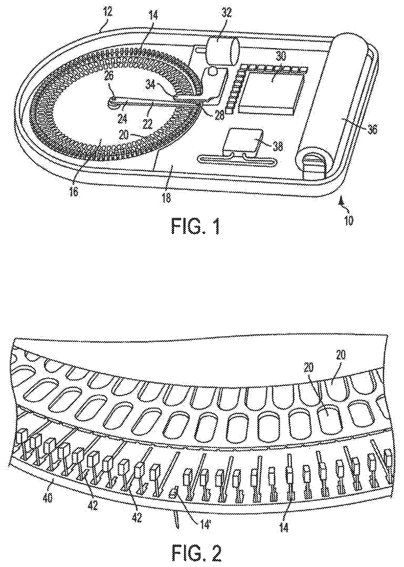
Accordingly, the invention relates to an analyte monitoring/drug (pharmaceutical agent) delivery device. The invention is suited for monitoring various blood constituents such as glucose. The device has a housing that at least partially encloses a plurality of microneedles disposed on a carrier and an electronics portion. Each microneedle is in fluid communication with a corresponding microchannel. Each microneedle is individually addressable. That is, each microneedle can be extended and retracted individually via an actuator. The electronics portion includes a processor and associated circuitry (e.g., memory, supporting electronics and the like), a motor or the like, a sensor, a power supply (e.g., battery) and optionally an interface.
In general, the processor controls the operation of the device and is data communication with the actuator, motor, sensor and interface. The invention provides for autonomous operation, that is, without intervention of the user. The invention can optionally provide for calibration without intervention of the user. The invention can also provide for semi-continuous monitoring for day and night time. The invention can provide for up to four, or more, weeks of operation. The invention can provide for a device that is relative small in size, and therefore unobtrusive. The invention can also provide for device with remote control and interactive electronics. The invention may be also used for the delivery of various pharmaceutical agents including high potency drugs to minimize patient intervention and minimize discomfort.
SUMMARY OF THE INVENTION
The invention relates to an analyte monitoring device operable to draw a fluid sample from a subject. The device has a first plurality of microneedles and a plurality of monitoring microchannels. Each of the first plurality of microneedles is at least intermittently in fluid communication with a corresponding monitoring microchannel. Each monitoring microchannel is also associated with a reagent. The device has at least one actuator operable to extend each microneedle to draw the fluid sample from the subject. The device also has a controller operable to initiate analyte testing of the fluid sample.
In a preferred aspect of the invention the actuator is operable to extend at least one of the first plurality of microneedles omnidirectionally. In another preferred aspect of the invention each of the first plurality of microneedles has an internal diameter in the range of about 25 to 200 micrometers. In another preferred aspect of the invention each of the first plurality of microneedles is fabricated from at least one of metal, plastic, glass and crystal. In another preferred aspect of the invention each of the first plurality of microneedles has a distal end that is operable to penetrate into a skin surface to a maximum of about 2.5 mm.
Preferably, the fluid sample is substantially blood. In another preferred aspect of the invention each of the first plurality of microneedles is at least intermittently in fluid communication with a monitoring microchannel via a conduit. In another preferred aspect of the invention each monitoring microchannel is operable to store the fluid sample and accumulation of the fluid sample in the monitoring microchannel is entirely dependent on capillary forces.
In another preferred aspect of the invention each of the monitoring microchannels has at least one internal surface that is at least partially coated with at least one insoluble material to enhance the capillary forces and minimize coagulation. In another preferred aspect of the invention the plurality of monitoring microchannels are fabricated in an array. In another preferred aspect of the invention the monitoring microchannels are fabricated in an array having approximately 50-150 microchannels formed in a maximum diameter of approximately 5 cm. In another preferred aspect of the invention each of the first plurality of microneedles is dimensioned for volumes of fluid in the range of about 50-500 nanoliters.
The device can be provided with a detector operable to determine when the fluid sample completely fills at least one monitoring microchannel such that the accumulation of the fluid sample with the associated microneedle may be terminated. In another preferred aspect of the invention at least one monitoring microchannel is in fluid communication with at least one reagent operable to assay for analytes selected from the group of (a) glucose, (b) cholesterol, (c) ethanol, (d) digoxin, (e) HDL cholesterol, (f) lithium, (g) sodium, (h) phenytoin, (i) theophylline, (j) cyclosporine, (k) cancer chemotherapy drugs, (l) DNA, (m) RNA, (n) extended phenytonin sodium, (o) warfarin sodium, and (p) proteins derived from blood.
Optionally, at least two monitoring microchannels are associated with a single microneedle so that multiple assays can be performed using a single microneedle. In another preferred aspect of the invention a second plurality of microneedles and a plurality of calibration microchannels filled with calibration fluid, wherein at least one assay is initiated for calibration purposes.
Optionally, the device can include a third plurality of microneedles and a plurality of pharmaceutical agent delivery microchannels wherein each pharmaceutical agent delivery microchannel is at least partially filled with a pharmaceutical agent. In another preferred aspect of the invention at least one monitoring microchannel is sealed with a polymer.
In another preferred aspect of the invention the controller is operable to initiate analyte testing based on a time schedule. In another preferred aspect of the invention the controller is operable to adjust the analyte testing time schedule.
In another preferred aspect of the invention the controller is operable to couple to a portable computing device. In another preferred aspect of the invention the portable computing device is a PDA. In another preferred aspect of the invention the controller and the portable computing device is operable to select or modify times for analyte testing.
In another preferred aspect of the invention the plurality of microneedles and plurality of monitoring microchannels are disposable. In another preferred aspect of the invention the controller and the actuator are reusable. In another preferred aspect of the invention the plurality of microneedles, plurality of monitoring microchannels, actuator and controller are portable.
The device can also include a heating source operable to heat at least one injection site prior to extending a microneedle. In another preferred aspect of the invention the heating source is an optical heating source.
The device can include a housing at least partially coated with an adhesive operable to attach the housing to a surface, wherein the housing at least partially enclosing the plurality of microneedles and the monitoring microchannels. In another preferred aspect of the invention the device includes a generally disc shaped housing at least partially enclosing the plurality of microneedles and the monitoring microchannels.
The invention is also directed to a pharmaceutical agent delivery device operable to deliver a pharmaceutical agent to a subject. The device has a first plurality of microneedles and a plurality of pharmaceutical agent delivery microchannels. Each of the first plurality of microneedles is at least intermittently in fluid communication with a corresponding pharmaceutical agent delivery microchannel. Each pharmaceutical agent delivery microchannel is at least partially filled with a pharmaceutical agent. The device has at least one actuator operable to extend each microneedle to deliver the pharmaceutical agent to the subject, and. The device also has a controller operable to initiate delivery of the pharmaceutical agent.
In a preferred aspect of the invention the actuator is operable to extend at least one of the first plurality of microneedles omnidirectionally. In another preferred aspect of the invention each of the first plurality of microneedles has an internal diameter in the range of about 25 to 200 micrometers. In another preferred aspect of the invention each of the first plurality of microneedles is fabricated from at least one of metal, plastic, glass and crystal. In another preferred aspect of the invention each of the first plurality of microneedles has a distal end that is operable to penetrate into a skin surface to a maximum of about 2.5 mm.
Preferably, the fluid sample is substantially blood. In another preferred aspect of the invention each of the first plurality of microneedles is at least intermittently in fluid communication with a pharmaceutical agent delivery microchannel via a conduit. In another preferred aspect of the invention the delivery of the at least one pharmaceutical agent delivery is at least partially dependent on hydraulic forces, preferred aspect of the invention the plurality of pharmaceutical agent delivery microchannels are fabricated in an array, preferred aspect of the invention the pharmaceutical agent delivery microchannels are fabricated in an array having approximately 50-150 microchannels formed in a maximum diameter of approximately 5 cm, preferred aspect of the invention each of the first plurality of microneedles is dimensioned for volumes of fluid in the range of about 50-500 nanoliters.
The device can include a detector operable to determine when the pharmaceutical agent delivery microchannel is empty. The device can also include a third plurality of microneedles and a plurality of monitoring microchannels wherein each monitoring microchannel is associated with a reagent. Preferably, at least one pharmaceutical agent delivery microchannel is sealed with a polymer.
In another preferred aspect of the invention the controller is operable to initiate pharmaceutical agent delivery based on a time schedule. In another preferred aspect of the invention the controller is operable to adjust the pharmaceutical agent delivery time schedule.
In another preferred aspect of the invention the controller is operable to couple to a portable computing device. In another preferred aspect of the invention the portable computing device is a PDA. In another preferred aspect of the invention one of the controller and the portable computing device is operable to select or modify times for analyte testing.
In another preferred aspect of the invention the plurality of microneedles and plurality of pharmaceutical agent delivery microchannels are disposable. In another preferred aspect of the invention the controller and the actuator are reusable. In another preferred aspect of the invention the plurality of microneedles, plurality of pharmaceutical agent delivery microchannels, actuator and controller are portable.
The device can include a heating source operable to heat at least one injection site prior to extending a microneedle. In another preferred aspect of the invention the heating source is an optical heating source.
The device can also include a housing at least partially coated with an adhesive operable to attach the housing to a surface, wherein the housing at least partially enclosing the plurality of microneedles and the pharmaceutical agent delivery microchannels. The device can also include a generally disc shaped housing at least partially enclosing the plurality of microneedles and the pharmaceutical agent delivery microchannels.
The invention is also directed to the combination of a device having an analyte monitor portion operable to draw a fluid sample from a subject and a pharmaceutical agent delivery portion operable to deliver a pharmaceutical agent to the subject. The device has a first plurality of microneedles and a plurality of monitoring microchannels. Each of the first plurality of microneedles is at least intermittently in fluid communication with a corresponding monitoring microchannel. Each monitoring microchannel is associated with a reagent. The device also has a second plurality of microneedles and a plurality of pharmaceutical agent delivery microchannels. Each of the second plurality of microneedles is at least intermittently in fluid communication with a corresponding pharmaceutical agent delivery microchannel. Each pharmaceutical agent delivery microchannel is at least partially filled with a pharmaceutical agent. The device has at least one actuator operable to extend each microneedle to either draw the fluid sample from the subject or deliver the pharmaceutical agent to the subject. The device also has a controller operable to initiate analyte testing of the fluid sample and delivery of the pharmaceutical agent.
The device can also include a third plurality of microneedles and a plurality of calibration microchannels filled with calibration fluid, wherein at least one assay is initiated for calibration purposes.
The invention it also directed to a method for automated analyte monitoring. The method includes providing a first plurality of microneedles and a plurality of monitoring microchannels. Each of the first plurality of microneedles is at least intermittently in fluid communication with a monitoring microchannel. Each monitoring microchannel is associated with a reagent. The method includes sequentially extending a microneedle thereby obtaining a fluid sample from a subject and then initiating analyte testing of the fluid sample. A controller is provided to automatically repeat the sampling and testing steps.
The invention is also directed to a method for automated pharmaceutical agent delivery. The method includes providing a first plurality of microneedles and providing a plurality of pharmaceutical agent delivery microchannels. Each of the first plurality of microneedles is at least intermittently in fluid communication with a corresponding pharmaceutical agent delivery microchannel. Each pharmaceutical agent delivery microchannel is at least partially filled with a pharmaceutical agent. The method includes extending a microneedle thereby delivering the pharmaceutical agent to a subject. A controller is provided to automatically repeat the pharmaceutical agent delivery step.
BRIEF DESCRIPTION OF THE DRAWING
FIG. 1 is a pictorial view of a portion of an analyte monitoring/drug delivery device in accordance with the invention.
FIG. 2 is a pictorial view showing additional structural details of the carrier microneedles, microchannels and conduit in accordance with FIG. 1.
FIG. 3 is a pictorial view showing additional structural details of the carrier microneedles, microchannels and conduit in accordance with FIGS. 1 and 2.
FIG. 4 shows an alternate embodiment of an analyte monitoring/drug delivery device in accordance with the invention.
FIG. 5 shows another alternate embodiment of an analyte monitoring/drug delivery device similar to the device shown in FIG. 4 also incorporating a fluidic capture and processing site in accordance with the invention.
FIG. 6 is a pictorial view showing additional details of the embodiment shown in FIG. 5 in accordance with the invention.
FIG. 7 is a pictorial view showing additional details of the embodiment shown in FIGS. 5 and 6 in accordance with the invention.
FIG. 8 is a pictorial view showing additional details of the embodiment shown in FIGS. 5-7 in accordance with the invention.
FIG. 9 shows another alternate embodiment of an analyte monitoring/drug delivery device in accordance with the invention.
FIG. 10 is a pictorial diagram showing a lead-screw drive mechanism for microneedle motion in accordance with the invention.
FIG. 11 is a pictorial diagram showing a straight microneedle with orthogonal entry in accordance with the invention.
FIG. 12 is a pictorial diagram showing a curved microneedle with orthogonal entry shown in three sequential positions in accordance with the invention.
FIG. 13 is a pictorial diagram showing a straight microneedle with angled entry shown in three sequential positions in accordance with the invention.
FIG. 14 is a pictorial diagram showing a curved microneedle with angled entry shown in three sequential positions in accordance with the invention.
FIG. 15 is a pictorial diagram showing a straight microneedle with a non-rectilinear motion shown in four sequential positions in accordance with the invention.
FIG. 16 is a pictorial diagram showing the basic configuration for improved sensitivity in accordance with the invention.
FIGS. 17a and 17b are pictorial diagrams showing an exemplary configuration for enhanced light collection using a spherical mirror to improve sensitivity in accordance with the invention.
FIGS. 18a and 18b are pictorial diagrams showing another exemplary configuration for enhanced light collection using a lenses and/or a prism to improve sensitivity in accordance with the invention.
FIGS. 19a and 19b are pictorial diagrams showing yet another exemplary configuration for enhanced light collection using a lenses and/or a prism to improve sensitivity in accordance with the invention.
FIG. 20a is a pictorial diagram showing enhanced blood collection by localized heating of capillary structures (blood) near puncture site in accordance with the invention.
FIG. 20b is a pictorial diagram showing an alternative structure for enhanced blood collection by localized heating of capillary structures (blood) near puncture site in accordance with the invention
FIG. 21 is a block diagram showing a feedback loop from blood sensor to control logic to control the depth of microneedle penetration in accordance with the invention.
FIG. 22 is a pictorial diagram showing force applied to the proximal end of a microneedle to cause the distal portion to project into multiple directions in accordance with the invention.
FIG. 23 is a graph showing the error in the volume of a 1 cm length of a nominal 88 micrometer tube by increased tube diameter.
FIG. 24 is a pictorial diagram showing an exemplary PDA display showing test times in accordance with the invention.
FIG. 25 is a pictorial diagram showing an exemplary PDA display showing dietary recommendations in accordance with the invention.
FIG. 26 is a pictorial diagram showing how data is entered into a Recommender System in accordance with the invention.
FIG. 27 is a pictorial diagram showing an exemplary PDA, Disposable and Reusable module in accordance with the invention.
FIG. 28 is a pictorial diagram showing exemplary locations on the body for placement of a device in accordance with the invention.
FIGS. 29a-29c are pictorial diagrams showing an exemplary embodiment suitable for location on the wrist.
FIGS. 30a-30b are pictorial diagrams showing an exemplary embodiment suitable for location on the waist.
FIGS. 31a-31b are pictorial diagrams showing an exemplary embodiment suitable for location on the arm.
FIGS. 32a-32b are pictorial diagrams showing an exemplary embodiment suitable for adhesive mounting in a variety of locations including the leg.
FIGS. 33a-33c are pictorial diagrams showing an exemplary embodiment suitable for strap mounting a device in accordance with the invention to the leg.
FIGS. 34a-34c are pictorial diagrams showing an exemplary embodiment suitable for clip and/or adhesive mounting a device in accordance with the invention to the waist via an undergarment.
DETAILED DESCRIPTION OF THE INVENTION
FIG. 1 shows a pictorial diagram of a portion of a analyte monitoring/drug (pharmaceutical agent) delivery device 10 in accordance with the invention. The device has a housing (lower portion only shown) 12 that at least partially encloses a plurality of microneedles 14 disposed on a carrier 16 and an electronics portion 18. The carrier 16, as shown in FIG. 1, is generally a planar substrate having a circular profile. It is understood that the carrier 16 can be formed with variety of different geometric shapes without departing from the invention.
A plurality of microchannels 20 are disposed on the carrier 16. Each microneedle 14 is in fluid communication with at least one microchannel 20. FIG. 1 shows an embodiment in which each microneedle 14 is in fluid communication with a single microchannel 20. Each microneedle 14 is individually addressable. That is, each microneedle 14 can be extended and retracted individually via an actuator. A variety of actuators are compatible with the invention.
FIG. 1 shows an embodiment in which each microneedle 14 can be extended and retracted via an actuator (a portion of which is not shown) including an arm 22 having a proximal end 24 supported by a hub 26 located generally in the center of the carrier 16. The arm 22 also has a distal end 28 that is generally disposed above a single microneedle 14.
The device also includes an electronics portion 18 having a processor 30 and associated circuitry (e.g., memory, supporting electronics and the like), a motor 32 or the like, a sensor 34, a power supply (e.g., battery) 36 and optionally an interface 38. In general, the processor 30 controls the operation of the device and is in data communication with the actuator, motor 32, sensor 34 and interface 38. Operation of the processor 30 and associated software is discussed in more detail below.
In the embodiment shown in FIG. 1, carrier 16 is movable so that each microneedle 14 is individually addressable (i.e., can be extended and retracted individually). The carrier 16 is rotatably mounted via hub 26 and is generally driven by motor 32. The connection between motor 32 and the carrier 16 can be accomplished via gears, belts and the like as discussed in more detail below. The interconnection of movable carriers and drive mechanisms suitable for use in conjunction with the invention based on the disclosure herein is well within the scope of one skilled in the art.
FIG. 2 shows some of the structural details of the carrier 16 shown in FIG. 1. The carrier 16 has a plurality of microneedles disposed generally adjacent to an edge 40. Microneedle 14' is shown in the extended position (the actuator is not shown). Each microneedle 14 generally has an internal bore in fluid communication with a microchannel 20 via a conduit 42. FIGS. 1 and 2 show microchannels that are generally disposed along a radial line extending between the hub 26 (disposed on a central axis) and the associated microneedle. The microchannels are generally shown in a nested configuration (i.e., two rows). This configuration is advantageous since it allows for microchannels that are generally wider than the microneedles and provides for increased microneedle density (i.e., more closely spaced microneedles) at the peripheral edge 40 of the carrier 16. It is understood that microchannels 20 can be positioned in a variety of geometric configurations without departing from the scope of the invention. It is also understood that conduits 42 can be routed in a variety of geometric configurations as necessary to link with the microchannels 20.
FIG. 3 shows additional structural details of the carrier 16, microneedles 14, microchannels 20 and conduits 42 generally in accordance with FIGS. 1 and 2. Microchannel 20 is preferably provided with a cover 88. Preferably the cover is at least partially translucent or transparent to facilitate optical detection of assays. The cover generally protects the contents of the microchannel from contamination. The cover can be generally rigid or flexible as discussed in more detail below.
Each microneedle 14 is formed with a proximal end 44 that interfaces with the microchannel 20, and a distal end 46 operable to penetrate the tissue or skin (for collecting a sample of blood or delivering a drug or pharmaceutical agent). The proximal end 44 is formed with an opening 48 that generally couples to the conduit 42.
In operation, a single microneedle 14 is moved into the extended position and penetrates the skin. Opening 48 is aligned with conduit 42 coupling the microneedle 14 with the microchannel 20 in fluid communication. The device is generally operable to function as a monitor and collect a sample of blood to be analyzed. The device is also operable to deliver a drug or pharmaceutical agent. Each microneedle 14 can be designated for monitoring or drug delivery. For monitoring, microneedle 14 is preferably associated with a "monitoring microchannel" configured for a specific assay technique (e.g., having a reaction layer) as discussed in more detail below. For drug delivery, microneedle 14 is preferably associated with a "pharmaceutical agent delivery microchannel" that is at least partially filled with the drug or pharmaceutical agent to be delivered as discussed in more detail below.
FIG. 4 shows an alternate embodiment of a device. In this embodiment, the plurality of microneedles 114 and the carrier (not shown) are generally stationary with respect to the housing (not shown). The microchannels are not shown although the location and interconnection of microchannels for use in conjunction with this embodiment of the invention based on the disclosure herein is well within the scope of one skilled in the art.
Each microneedle 114 has a proximal end 144 extending towards a central axis 178 and distal end 146 directed downward (i.e., directed at the skin or tissue). The proximal end 144 of each microneedle 114 is preferably anchored or coupled to the carrier. Each microneedle 114 generally includes a curve or bend 176 thereby defining a ramp portion 160 formed between the proximal and distal ends. In this embodiment, the anchored proximal end 144 and ramp portion provide an incline used to extend the microneedle 114 as well as a spring biasing of the microneedle in the retracted position. Other arrangements for spring biasing the microneedle are readily apparent to those skilled in the art.
The actuator includes a cam 162, a track 164 formed with slots 166 and a slider 168 having an index pin 170. The actuator also includes a motor (not shown) or the like for driving or rotating the cam about the central axis 178. The connection between such a motor and the cam 162 can be accomplished via gears, belts and the like as discussed in more detail below. The interconnection of cam and drive mechanisms suitable for use in conjunction with the invention based an the disclosure herein is well within the scope of one skilled in the art.
The slider 168 is movable between a retracted position (closer to the central axis) and an extended position (further from the central axis). In the retracted position, the slider is disposed generally above the ramp portion 160 of at least one microneedle 114 and preferably does not contact the microneedle. The slider is also preferably biased or spring loaded in the retracted position. Biasing mechanism or springs are not shown. However, the biasing mechanisms or spring loading of a slider for use in conjunction with the invention based on the disclosure herein is well within the scope of one skilled in the art. The slider shown in FIG. 4 is generally shown between the retracted and extended position.
As cam 162 rotates, it pushes the slider 168 outward along the track 164. The slider has a lower portion 172 operable to contact a single microneedle 114 as the slider moves from the retracted position to the extended position. The index pin 170 is slidably engaged in slots 166, thereby restricting the slider to motion along a linear path (along the ramp portion 160 of a single microneedle 114). As the slider moves along the ramp portion 160, the distal end 146 of the microneedle 114 is forced downward (e.g., into the tissue for collecting a sample or delivering a pharmaceutical agent). Once the cam reaches its maximum lobe height 174, the slider 168 returns to the retracted position allowing microneedle 114 to respond to spring biasing forces and withdraw from the tissue.
The track 164 generally has a proximal end 165 that is pivotally engaged along the central axis. Once the slider 168 returns to the retracted position allowing microneedle 114 to spring out of the tissue, track 164 is then advanced (i.e., rotated clockwise or counter-clockwise) to index or address to the next microneedle 114. The cycle can then be repeated.
It is understood that microneedles 114 do not have to be continuous in structure. For example, a fluidic capture and processing site can be located at the bend 176 of each microneedle 144. This site can interface with a fluidic layer positioned below the microneedles. When the microneedle is fully depressed, it preferably aligns with the fluidic processing layer forming a continuous fluid path. This path preferably remains sealed until the microneedle 114 is pressed down.
FIG. 5 shows another alternative embodiment of a device incorporating a fluidic capture and processing site as discussed above. In this embodiment, the plurality of microneedles 214 and the carrier 216 are generally stationary with respect to the housing (not shown). Each microneedle 214 has a distal end 246 directed downward (i.e., directed at the skin or tissue) and a proximal end 244 engaged in fluidic capture site 280. A spring member 261 is coupled between the fluidic capture site 280 and the carrier 216 thereby defining a spring biased ramp portion 260.
The actuator includes a cam 262 having a tooth 284, a track 264 formed with at least one slot 266 and a slider 268 having an index pin 270. The actuator also includes a ring gear 282 that is coupled to housing (not shown) and is generally stationary with respect to the track 264. As discussed above, the track 264 is pivotable around the central axis 278. The actuator also includes an idler gear 286 that driven by the tooth 284 as discussed in more detail below. Idler gear 286 has a pivot point that is anchored to the track 264, and generally moves the track in an incremental fashion, to index or address successive microneedles 214.
The slider 268 is movable between a retracted position (closer to the central axis) and an extended position (further from the central axis). In the retracted position, the slider is disposed generally above the ramp portion 260 of at least one microneedle 214 and preferably does not contact the microneedle. The slider is also preferably biased or spring loaded in the retracted position. Biasing mechanism or springs are not shown. However, the biasing mechanisms or spring loading of a slider for use in conjunction with the invention based on the disclosure herein is well within the scope of one skilled in the art. The slider shown in FIG. 5 is generally shown in the retracted position. Microneedles 214' and 214'' are shown in an intermediate position and the extended positions respectively for illustrative purposes only.
As cam 262 rotates (clockwise), it pushes the slider 268 outward along the track 264. The slider has a lower portion operable to contact a single microneedle 214 as the slider moves from the retracted position to the extended position. The index pin 270 is slidably engaged in slot 266, thereby restricting the slider to motion along a linear path (along the ramp portion 260 of a single microneedle 214). As the slider moves along the ramp portion 260, the distal end 246 of the microneedle 214 is forced downward (e.g., into the tissue for collecting a sample or delivering a pharmaceutical agent).
Once the cam reaches its maximum lobe height, the slider 268 returns to the retracted position allowing microneedle 214 to spring out of the tissue. Tooth 284 engages the idler gear 286 and advances the gear by one tooth. Track 264 is then advanced (i.e., rotated counter-clockwise) to index or address to the next microneedle 214. The number of teeth on idler gear 286 and ring gear 282 are selected so that each single tooth movement of the idler gear 286 results in the proper angular displacement of the track 264 to precisely index or address the next microneedle 214. The cycle can then be repeated.
FIGS. 6-8 are pictorial views showing additional details of the embodiment shown in FIG. 5. Continuing with the discussion above, once microneedle 214 is in the extended position, the proximal end of the microneedle 244 and fluidic capture site 280 interfaces with a microchannel 220. The fluidic capture site is formed with an opening that generally couples to a conduit 234 and ultimately microchannel 220 as discussed with respect to FIG. 3.
In a monitoring configuration, depression of microneedle 214 results in the collection of blood in microchannel 220. Microchannel 220 is preferably configured for a specific assay technique (e.g., having a reaction layer) as discussed in more detail below. The reaction is preferably monitored by sensor 234 mounted to the 268 slider generally disposed above microchannel 220.
Microchannel 220 is preferably provided with at least some form of cover. Preferably the cover is at least partially translucent or transparent to facilitate optical detection of assays. See e.g., cover 88 in FIG. 3. The cover generally protects the contents of the microchannel from contamination. The cover can be generally rigid or flexible. For delivery of a drug or pharmaceutical agent, the drug is preferably fluid is stored in a compressible microchannel (e.g., a microchannel having a flexible cover). As the slider 268 moves towards the extended position it preferably presses the microneedle 214 into the skin or tissue. As the microneedle is inserted the slider can at least partially compressing microchannel 220 and forcing the fluid out through the conduit 242 and ultimately the microneedle 214 and into the skin or tissue. It is understood that both monitoring and drug delivery be carried out within the same device by allocating a portion of microneedles 214 for each task.
It is also understood that other mechanisms can be used to facilitate delivery of pharmaceutical agents. For example, a small fluidic pump can provide positive pressure to the microchannel. The pharmaceutical agent contained in the microchannel is then expelled through the through the microneedle. Optionally, a capacitance detector can be used to sense that the microchannel is empty and can signal that the fluidic pump should be turned off, thereby controlling the possibility of air entering the delivery system.
FIG. 9 shows another alternative embodiment of a device 310 in accordance with the invention. The device has a housing (only partially shown) 312 that at least partially encloses a plurality of microneedles 314 disposed on a carrier 316. The carrier 316 is generally a planar substrate having a ring-like profile. It is understood that the carrier 16 can be formed with variety of different geometric shapes without departing from the invention.
A plurality of microchannels 320 are disposed on the carrier 316. In this embodiment, the 388 cover is arranged on an inside edge 340 of the substrate 316. Each microneedle 314 is preferably in fluid communication with a single microchannel 320. Each microneedle 314 is individually addressable.
FIG. 9 shows an embodiment that is somewhat similar to FIG. 1 in that each microneedle can be extended and retracted via an actuator (a portion of which is not shown) including an arm 322 having a proximal end supported by a hub 326 located generally in the center of the device. The arm 322 also has a distal end 328 that is generally disposed above a single microneedle 314.
The device also includes an electronics portion having a processor 330 and associated circuitry (e.g., memory, supporting electronics and the like), a motor or the like (not shown), a sensor 334, a power supply or battery (not shown) and optionally an interface (not shown).
In the embodiment shown in FIG. 9, the plurality of microneedles 414 and the carrier 316 are generally stationary with respect to the housing 312. The connection between the drive motors and the arm 322 is not shown. This can be accomplished via gears, belts and the like as discussed above. The interconnection of the microchannels 320, microneedles 414, conduits, drive mechanisms and the like in conjunction with the invention based on the disclosure herein is well within the scope of one skilled in the art.
Exemplary System Segmentation
Three exemplary system modules have been identified to optimally meet the requirements of a user friendly, diagnostically relevant, and low cost analyte monitoring/drug (pharmaceutical agent) delivery system. The analyte monitoring/drug (pharmaceutical agent) delivery system, is preferably partitioned into a Disposable Module, a Reusable Module and a PDA Module. See e.g., FIG. 27. This configuration optimally distributes functionality amongst these three configurations to achieve certain advantages. However the invention is not limited to this configuration. For example, a one-unit disposable device including all electronics, microneedles, chemistry, mechanics and user interface may be alternatively employed. Or, more relevantly, the design of the invention allows for any distribution of components between one or more system modules. For example, components may be partitioned among one or more system modules based on the overall system cost, user safety and/or performance concerns.
The Disposable Module
This module contains those components that once used must be discarded to maintain biological safety and diagnostic accuracy. This module preferably includes any structural or mechanical elements to maintain integrity, sterility and an electromechanical interface to any reusable components. Therefore this system module preferably includes: microneedles, a microfluidic assembly, membrane, reagent chemistry and associate housing materials. This module can also include retaining mechanisms for establishing and maintaining intimate contact with the body thereby providing mechanical retention of the analyte monitoring/drug (pharmaceutical agent) delivery system.
The Reusable Module
This module preferably contains those components that control, automate motion, measure the glucose reaction, alarm the user, transmit data to the PDA module. This module can also include retaining mechanisms for establishing and maintaining intimate contact with the body thereby providing mechanical retention for the analyte monitoring/drug (pharmaceutical agent) delivery system. Preferably, this module includes: a microprocessor with associated circuitry (e.g., memory, supporting electronics and the like), a sensor (e.g., an electro-optical sensor) for evaluating the products of any reactions (e.g., glucose reactions), drive mechanisms such as motors or the like, a sensor, a power supply (e.g., battery) 36 and an interface operable to communicate with a portable computing device or PDA. The interface can be RF, magnetic or inductive, optical or the like. Using magnetic or inductive coupling rather than RF coupling is advantageous since it can potentially avoid FCC restrictions or limitations. The reusable module can also an audible or vibration alarm to notify the user that user action intervention is required.
The PDA Module
This module preferably includes a separate user interface via a portable computing device such as a personal digital assistant (PDA), handheld computer or the like for controlling and/or interacting with the device. A typical portable computing device includes a processor, memory, associated circuitry, a display (e.g., monochrome or color LCD) and an input device such as a key pad, touch screen (e.g., integrated with the display) or the like and an operating system. Previously available glucose monitors were specifically designed for handling the paper test strips, for viewing numerical values of the glucose measurements and for setting other parameters of the meter such as its calibration. These custom designed units had limited functionality and relatively crude user interfaces.
Today, portable computing devices with improved operating system software and user interfaces are readily available. These devices provide the potential for richer and extended functionality. For example a typical PDA includes a relatively large viewing screen (important to the many diabetic elderly) and can also include wireless communications mechanisms, a sophisticated operating system and a variety of business and personal software (calendars, scheduling, etc.). Accordingly, a PDA provides a robust platform for developing diabetic related software. Recently the FDA approved the first PDA for monitoring EKG activity. The invention preferably includes the use of a PDA to provide the proprietary software (programs) for autonomous operation with an improved user interface.
To this end, the PDA module preferably provides the user with software that facilitates informed decisions to help the diabetic user more optimally adjust either drug or dietary consumption to more optimally control glucose. The PDA configuration provides a user interface and preferably allows users the ability to program and or control testing. The user can view individual glucose measurements and graphically display glucose value trends by the day, week or custom time period. The PDA can be used to display any and all of the measurements recorded by the system. Using the proper software, the user can be provided with recommendations for drug regiment modification (insulin or other). The user can also be provided with recommendations for dietary changes. See FIG. 25. The PDA can also store grocery lists for daily menus. The grocery list can be viewed by the user as needed to ensure proper dietary intake.
The user can preferably program the times when their analyte tests are to be taken. Preferably, the user can also set the upper and lower limits for alerts. As shown, a graphic showing a clock can be easily used to select or modify times for testing. See FIG. 24.
Whenever the user makes changes and with verification from the user, the information is wirelessly downloaded to the system. During the day the user will not need to use the PDA unless alerted by the system to check for an analyte reading. The user can initiate a test from the PDA if wanting to make an immediate measurement. Once the user selects this command, verifies it, and transmits it to the Reusable, a confirmation is made back to the PDA.
An increased number of tests per day can be accommodated for a shorter use life. For example, a newly diagnosed diabetic can have a 24 test per day regiment for the first 6 days to ascertain maximum peaks and lows with various daily regiments of exercise, stress and food types. Then with the user profiled, the caregiver may reduce the number of tests to an appropriate level. Additional aspects of the PDA module and associated software is discussed below.
Exemplary Microneedle Structures
The invention encompasses mechanisms operable to extend a microneedle that is smaller than most used today for injection or blood extraction (referred to herein as a microneedle). The use of microneedles allows for the extraction of blood with minimal discomfort or pain. It has been noted that blood extraction by the mosquito is efficient. This insect has managed to do what man cannot, that is, to extract blood essentially without pain while drawing blood through a micrometer hollow member.
The mosquito accomplishes blood extraction by use of a proboscis which consists of two tubes surrounded by two pairs of cutting stylets that are together in a tight bundle. This bundled entity is called the fascicle and the bundle is about 40 to 60 micrometers in diameter. The fascicle breaks the skin surface of the victim with its stylets. Once below the surface, the fascicle bends at a sharp angle to begin exploring for blood. With each insertion, the mosquito attempts to hit a venule or arteriole. On each try, the mosquito will withdraw the fascicle slightly while leaving it in the original hole, and angle it in a different direction. Once blood is found, the mosquito may draw blood for about ninety seconds and will draw a few micrograms, e.g., 5 microliters, of blood. The invention encompasses technology that mimics the function of the mosquito and within the disclosed analyte monitor/drug delivery system.
The diameter of a microneedle is, for example, optimally about 40 to 120 micrometers, approximately the size of the mosquito's proboscis. Preferably, the microneedle is driven into the skin or tissue to a depth to yield a sample that is mostly blood with minimal interstitial fluid. The microneedle preferably has an internal diameter of about 25 to 100 micrometers, sufficient for blood to flow freely and, preferably, to flow by capillary action. Needles of this type have been demonstrated by Kumetrix, Inc. (e.g., a MEMS based silicon microneedle having an internal microfluidic channel approximately 25 micrometers in width, providing very strong capillary forces but allowing the erythrocytes to flow without difficulty).
The invention is alternatively operable with standard hypodermic tubing rather than silicon MEMS microneedles (e.g., to achieve sufficient strength at low cost). Hypodermic tubing is currently available in sizes down to 75 micrometers in diameter. Alternatively the microneedles can be made from glass and drawn to thin diameters similar to the way hollow capillary tubing is drawn. It is understood that microneedles suitable for use in conjunction with the invention can be fabricated by a variety of methods. It is also understood that microneedles suitable for use in conjunction with the invention can be fabricated from a variety of materials including, but not limited to, metal, plastic, glass and crystal (e.g., quartz).
The microneedle can be either straight or curved and enter the skin rectilinearly, curvilinear or obliquely. Orthogonal entry with rectilinear motion is potentially the simplest to achieve, advantageously requiring a minimal length of tubing below the epidermis. See FIG. 11. A potential disadvantage is that the minimum length may fail to erupt or puncture enough blood vessels to cause blood to flow in sufficient volume. Entering the skin obliquely increases the number of potential blood vessels skewered but may aggravate more nerve endings. Making the microneedle curved also tends to access more tissue and can enhance collection by crossing more blood vessels without penetrating deeply. The orthogonal method will be optimal where blood is acquired readily and where nerve ending are rich. The oblique or curved microneedle approach is optimal where nerve fibers are less dense.
As an alternative to a straight microneedle having an orthogonal entry, a curved microneedle can be used with orthogonal entry. See FIG. 12. In the alternative, a straight microneedle can be used with angled entry. See FIG. 13. In the alternative, a curved microneedle can be used with rotational entry. See FIG. 14. In the alternative, a straight microneedle can be used with a non-rectilinear motion. See FIG. 15. The alternate approach shown in FIG. 15 utilizes motion that does not match the shape of the microneedle. This results in the microneedle penetrating one layer of tissue with minimum disruption while producing more disruption at other depths. This effect can be used to minimize pain while still disrupting enough blood vessels to enable sufficient sample collection. FIG. 15 shows a straight microneedle with circular motion, steps 1 to 4, where the center of the motion is well above the surface of the skin. Other motion forms are anticipated including complex forms.
The microneedle is preferably extended and retracted mechanically. Microneedle extension and retraction can be powered by a single device or a combination of devices. For example, a DC motor can be used to drive an extending means and a spring can provide the return force. Alternatively, a powered source such as a DC motor can both drive the microneedle into and out from the skin. The later is a preferred approach in that it provides optimal control over the microneedle position.
The additional advantage of the articulated microneedle drive is that it mimics the exploratory motion of the mosquito. The microneedle can be driven to a maximal depth in one area and then, without removing it from the skin, reciprocate the microneedle and cause it to move in a new direction. In order to cause a new direction at a remote point on a penetrating microneedle, a stress must be imposed on the microneedle external to the skin while the distal end of the microneedle is still in the skin. See FIG. 22.
It is understood that various techniques can be used to drive the microneedles in accordance with the invention. Aside from the techniques discussed above, extending and retracting the microneedle can be accomplished using a micro-miniature DC motor and associated gear train. See e.g., FIG. 10. In this embodiment rotational output of the motor (not shown) is transferred through a gear train 492 to an internally threaded gear 494 located above the microneedle 414. The rotation of the gear causes a `leadscrew` 490 to move linearly to gear rotation. Thus the motor causes a drive to extend or retract the microneedle 414. This design can achieve the penetration forces necessary, a value that is dependent on skin type, thickness and physical microneedle parameters, typically in the range of 0.01 to 0.07 Newtons.
The lead screw drive mechanism is preferably driven by a captured nut forcing the screw to travel co-linear with the intended microneedle travel. The lead screw engages with the microneedle assembly, pushes the microneedle into the tissue, pulls the microneedle out and disengages from coupling 496. The drive mechanism preferably pivots to engage the next microneedle assembly. The nut can be driven by gears as shown in FIG. 10, or a belt or other motion transfer mechanisms. The back end of the microneedle can be accessed by various techniques including but not limited to an opening in the engagement mechanism, an opening in the microneedle side or a bend in the microneedle exposing the proximal opening. Incorporation of a leadscrew mechanism suitable for use in conjunction with the invention based on the disclosure herein is well within the scope of one skilled in the art.
Other motion generating sources or motion conveyance can alternatively be used. For example, the motor can drive a cam device with features that cause the microneedle to extend downward with a predetermined rate profile. Cam features, or springs, can be used to retract the microneedle. Also, a shape memory alloy material (SMA) can be used to cause the microneedle to extend down and back. The heating and cooling of the SMA can cause the appropriate amount of force and displacement. A solenoid type device can be used to either drive the microneedle directly or index the microneedle. Such a device can be used like a motor.
Having articulated motion allows the microneedle to be extended into the skin incrementally to the correct depth. This invention is suitable for use on skin surfaces where a relatively flat surface is available equal to or larger than the a real dimension of a wrist. Although, the invention can be configured to acquire blood from more curving surfaces such as a finger. The invention is preferably configured to acquire blood from specific places such as the upper arm, wrist, abdomen, back, thigh or lower leg. The invention can be disposed or worn beneath clothing to render it inconspicuous.
Exemplary device configurations for differing body locations are discussed in more detail below. Depending on the location selected, the thickness of the skin surface and depth to the capillary bed is variable. For example, the epidermis varies in thickness from 0.02 mm at the eyelids to 1.4 mm on the soles of the feet. The dermis likewise varies from 0.6 to 2.5 mm. The invention is preferably configured to have a distal end of the microneedle reside into the vascular plexus but not go to a depth sufficient to penetrate the deep dermal vascular plexus. Accordingly, the invention preferably operates over a range of about 1.0 to 2.0-mm penetration into the skin surface.
Exemplary Sensor Structures
Various sensor structures are compatible with the invention. For example, optical detection can be achieved by techniques such as colorimetry and fluorescence. FIG. 16 shows basic configuration having a microchannel 520 and a reaction layer 521 in fluid communication with a microneedle 514. The reaction layer can be a membrane that is coated with a chemically active components that provide a change in color in the presence of the desired analyte (e.g., glucose) for colorimetric measurements. A fluid sample is collected via microneedle 514 and is stored in microchannel 520. The appropriate reagent is preferably contained within the microchannel 520 so that a reaction is initiated upon collection of the fluid sample. The sensor is disposed generally above the microchannel 520 and has an emitter 535 operable to illuminate the reaction layer with an appropriate frequency of light. The sensor also has a detector 537 operable to detect light reflected off of the reaction layer as shown by arrows 539. The detector 537 can be implemented using a photodiode with single or multiple picture elements (pixels). The example of such a device is a CMOS or CCD imager. The emitter and detector are preferably controlled by the processor (not shown). The detector output is preferable read by the processor and is further processed in order to determine the results of the reaction. FIGS. 17a and 17b show an enhanced collection configuration to improve sensitivity. This sensor configuration includes a spherical mirror 541 for reflecting light from one or more emitter 535 to the detector 537.
FIGS. 18a and 18b show alternative sensor configurations. FIG. 18a shows a microchannel 520 and a reaction layer 521 in fluid communication with a microneedle 514. Also shown in FIG. 18a is a cover 588 as discussed above. The reaction layer 521 can be a membrane or porous media that is coated with a chemically active component that changes color in the presence of the desired analyte (e.g., glucose) for colorimetric measurements. A fluid sample is collected via microneedle 514 and is stored in microchannel 520. The appropriate reagent is preferably contained within the microchannel 520 so that a reaction is initiated upon collection of the fluid sample. The sensor is disposed generally above the microchannel 520 and has an emitter 535 operable to illuminate the reaction layer with the appropriate frequency of light. The sensor also has a detector 537 operable to detect light reflected off of the reaction layer 521. Lenses 543 are disposed between the between the emitter 535 and the reaction layer 521 as well as between the detector 537 and the reaction layer 521. Lenses 535 generally focus the light for improved illumination of the reaction layer 521 and light collection at the detector 537. FIG. 18b is similar to FIG. 18a but includes a coupling prism 589 disposed on the cover to improve performance of the detector.
FIGS. 19a and 19b show further alternative sensor configurations. FIG. 19a shows a microchannel 520 and a reaction layer 523 in fluid communication with a microneedle 514. Also shown in FIG. 19a is a cover 588 as discussed above. The reaction layer 523 is shown as a generally thin layer having assay reagents mixed in a support matrix applied to the microchannel 520. A fluid sample is collected via microneedle 514 and is stored in microchannel 520. The appropriate reagent is preferably contained within the microchannel 520 so that a reaction is initiated upon collection of the fluid sample. The sensor is disposed generally above the microchannel 520 and has an emitter 535 operable to illuminate the reaction layer with the appropriate frequency of light. The sensor also has a detector 537 operable to detect light reflected off of the reaction layer 523. Lenses 543 are disposed between the between the emitter 535 and the reaction layer 523 as well as between the detector 537 and the reaction layer 523. Lenses 535 generally focus the light for improved illumination of the reaction layer 523 and light collection at the detector 537. FIG. 19b is similar to FIG. 18a but includes a coupling prism 589 disposed on the cover to improve performance of the detector. It is understood that the microchannel cover 588 can be enhanced with a variety of optical properties such as lenses, filters, reflective structures, refractive structures and the like without departing from the invention.
Enhanced Blood Collection
The invention also encompasses various techniques for enhanced blood collection. FIGS. 20a and 20b show the use of heating sources (e.g., infrared emitting LED) to heat the tissue near the collection site. Heating the capillary structure of the tissue at the collection site can lead to improve the blood supply and enhanced collection using microneedles. FIG. 20a shows an exemplary microneedle 514 inserted in skin or tissue. Heating source 598 is located to one side of the microneedle and is directed towards the tissue thereby heating the tissue in which the microneedle is inserted. FIG. 20b shows an alternate embodiment in which the heating source 599 is generally ring shaped and is located coaxially around the microneedle 514.
Automatic Detection of Blood
To simplify the acquisition of blood and to assure that an adequate sample is taken this invention encompasses the use of a blood detection sensor. The blood detection sensor provides control over the penetration and extraction control. The sensor feedback loop works by incrementally driving the microneedle into the skin, waiting an appropriate time for blood to fill the microneedle and sensor and then retracting the microneedle. See FIG. 21. If no blood is detected within a reasonable period of time, then the motor can further drive the microneedle to a greater depth. When blood has been acquired the microneedle is retracted.
The blood-sensor can be located at various points along the blood path (e.g., microneedle, microfluidic channel, microfluidic well or at the reaction site) of the test device or preferably, the test means itself is the sensor. The optical sensor for the colorimetric test can detect the appearance of blood, prior to making a reading to ascertain the glucose level. This provides dual function of the sensing device and provides a feedback loop without additional cost. Alternatively, a capacitance, conduction or resistive sensor can be used in the microfluidic channel or well to determine when liquid is present.
Since the depth and rate at which blood is acquired are site, user and time specific there is need to have these variables stored in the system. Since it is envisioned that this device be used with a cartridge containing a multiplicity of microneedles, and since each blood acquisition is a repetitive search and detect methodology, it is helpful to the user if the system could optimize itself to achieve minimal blood acquisition time.
Analyte Testing and Delivery of Pharmaceutical Agents
Since 1987, the American Diabetes Association (ADA) has provided criteria for the statistical assessment of self-monitoring blood glucose (SMBG) meters. In 1987, the ADA recommended blood glucose measurements should be within 15% of the reference and that future SMBG meters should have less than 10% variability. By 1993, it was evident new technologies, at this time, were not achieving the 1987 goals. However, in 1996, the ADA recommended less than 5% variability for future SMBG meters.
In comparison to this standard, recent evaluation of the relative accuracy of selected, available SMBG meters, representing visual, colorimetric and amperometric detection, showed that current products vary from a reference by approximately -5 to +20%. The significance of statistical errors for SMBG meters depends on clinical assessment, that is, whether the error results in inappropriate clinical management.
Recognizing that SMBG meters using relatively large microliter volumes of blood show large statistical errors. The invention contemplates the use of small (e.g., nanoliter) volumes for samples. This helps to achieve the small size of the device necessary for ambulatory monitoring. The requirement of new design and precision manufacturing approaches, as noted, are the subject of this invention, i.e., to achieving better accuracy. The invention contemplates the use of small (e.g., nanoliter) volumes for samples. In addition to achieving better accuracy, this also helps to achieve the small size of the device necessary for ambulatory monitoring. The requirement of new design and precision manufacturing approaches, as noted, are the subject of this invention.
In order to support small volume fluid assays, the invention incorporates microfluidic channels with a reagent membrane for a plurality of blood analyte testing. FIG. 3 shows an exemplary array of microchannels 20 each with precise dimensions, that is, micrometer dimension tolerances. A membrane can be bonded onto the array to prevent the migration of red blood cells, but not liquid blood constituents. The unbonded side of the membrane is preferably coated with assay reagents either uniformly or in spatial defined locations, that is, the channel locations. When blood enters an individual microchannel, the dimension of the microchannel determines the volume. This is critical to the precision of the assay, that is, filling the microchannel provides the analytical volume for assay. Subsequent to filling, the blood constituents migrate through the "reaction layer" (e.g., a polymer) and initiate, by wetting, the assay chemistries within the reaction layer as discussed herein.
The polymer for the reaction layer, may be any commercial polymer suitable for the desired assay whereby, by wetting, the assay chemistries may be initiated within or on the other side of the polymer layer. Preferred polymers include hydroxyethyl cellulose, sodium alginate and gelatin. The reaction layer is preferably cast on polymers such as styrene or any polymer of high liquid transmittance and capability for sealing. The polymer and reaction layer is preferably sealed to the capillary well using a device with precision dimensions to surface bond the polymer and reaction layer using adhesive bonding by heat, adhesive materials or other means or agents.
The need for precision in the dimension of the device is evident from FIG. 23. This figure shows the error in the volume of a 1 cm length of a nominal 88 micrometer tube when the tube diameter is increased (e.g., a 5% error occurs with a nominal 91 micrometer diameter tube). It can be seen that a change in diameter of less than 3 micrometers in a nominal 88 micrometer diameter tube can result in an approximately 5% error in volume. Accordingly, the tolerance required to control volume to less than 5% is on the order of <3 micrometers.
The assay chemistries can be based on widely used techniques such as the Trinder reaction. The Trinder reaction is based on a coupling reaction between two dye precursos, viz., beta-D-glucose+O.sub.2+H.sub.2O=D-gluconic acid+H.sub.2O.sub.2 (1) 2H.sub.2O.sub.2+4-aminoantipyrine+1,7-dihydroxynaphthalene=red dye (2) in the presence of glucose oxidase for the first reaction and in the presence of a peroxidase for the second reaction. The Trinder reaction is widely used for glucose assays. The important features of the Trinder reaction are the long history of use, the stability of the dye precursors with elevated temperatures and the availability, and thermal stability, of the enzymes. The 1,7-dihydroxynaphthalene is soluble only in alcohol and a water soluble aromatic is preferred. This aromatic is preferably one of the water soluble reagents identified in U.S. Pat. No. 4,350,762--DeLuca, et al., for example, the sodium salt of 2,4-dichlorophenyl sulphonate.
The specific configuration of the invention differs from prior technology in a number of ways including but not limited to the examples discussed below. The invention incorporates micromachined, or micromolded, microchannels with precise dimensions, that is, micrometer dimension tolerances. The accumulation or delivery of fluid (e.g., blood, pharmaceutical agent . . . ) is direct, that is from a microneedle. The accumulation of fluid in the microchannel is entirely dependent on capillary forces. The microchannel surfaces may be thinly coated with insoluble materials, such as various polymers, to enhance the capillary forces and minimize blood coagulation. The microchannels can be fabricated as an array in large number, e.g., 150 on a 1.5'' diameter. The microchannels can be dimensioned for minimal fluid volumes (e.g., 100-500 nanoliters of fluid or less).
The microchannels can be provided with a mechanism to detect when the fluid completely fills the device such that use of the associated microneedle can be terminated (i.e., the microneedle can be retracted), as discussed below. The microchannels and assay chemistries may be applied to assays for analytes other than glucose. The invention can be modified to provide multiple channels for multiple assays using a single blood sample. So called "calibration microchannels" may be initially filled with calibration fluid and the assay initiated for calibration purposes as discussed in more detail below. This aspect of the invention can only be realized with the structures disclosed herein as discussed in more detail below. The microchannels may be filled with drug and used to deliver drugs used in small doses (high potency). The capability to deliver drug and or monitor blood analytes in an automated fashion using a portable device can only be realized with the structures disclosed herein.
Ultimately, the invention encompasses the combination of both the monitoring and pharmaceutical agent delivery system within one unit (preferably a disposable unit). For example, military personnel may be unknowingly exposed to a toxin. The device can periodically extract blood and assay for predetermined toxins. If a toxin is detected, the device can deliver antidote.
Self Calibration
In order to increase the accuracy of an enzymatic test, it has been found helpful in current SMBG meters to provide, with each batch of test strips, a calibration factor that is a correction factor to be used to more accurately determine the correct result. Two calibrations are needed--one to compensate for instrument components and secondly to compensate for the particular sensitivity of a specific batch of chemical components. Various techniques have been developed to achieve this in an automated fashion.
The invention preferably incorporates autonomous self-calibration functions so that no user actions are required. One or more calibration microneedles (i.e., associated with a calibration microchannels) are preferably incorporated in the microfluidic structure. When the calibration microneedle is actuated, it is pushed down but no microneedle extends from the disposable unit. In the fully extended position, the unit releases a calibration fluid into the microfluidic channel. For example, in the extended position the calibration fluid travels through the conduit and fills the microchannel. The assay system provides a measure of the glucose in the calibration solution and compares this measure value with the known value. Preferably, a correction factor is derived from the calibration process. The correction factor is preferably stored electronically and is utilized during subsequent analyte testing.
A plurality of calibration microneedles can be used to compensate for any change in reagent or instrument properties. Thus the first measurement taken with the insertion of a new Disposable is to calibrate the meter. Subsequent measures are made on a timed basis and are used by the system software to compensate for change in reagent properties at room temperature.
Testing for Other than Glucose
The invention can be utilized to test for a variety of constituents including but not limited to enzymes, antibodies, alcohol level and other blood constituents. The invention can be designed to also incorporate HbAlc (glycosylated hemoglobin) blood testing, which is a test diabetics should have done about twice a year or more and provides a measure of long term effectiveness in regulating blood glucose levels. Virtually any blood test that has chemistries that can be used at or near body temperature can be incorporated within this system. It is also envisioned that the invention can provide Polymerase Chain Reaction (PCR) testing to genetically identify foreign bodies within the blood. A relatively small heating element can be provided for resting that utilizes heat melts of duplex nucleic acid. Insulation can also be provided to minimize any heating of surrounding structure.
4. Alternate Assay Technologies
A review of the literature shows, by select examples, that a variety of colorimetric, electrochemical and fluorescent assay methods are available. Of these methods, U.S. Pat. No. 6,118,126--Zanzucchi discloses fluorescence assay techniques and this technology may be used as an alternate method of assay for the device of this invention. This technology allows for the enhancement of fluorescence from textured surfaces. In connection with the invention, enhanced fluorescence can provide improved sensitivity for the assay of small samples. It is understood that a variety of other assay techniques can be used without departing from the scope of the invention.
Use of a Neural Network to Optimize the Acquisition of Blood
In order to make the system more user friendly, a simple learning algorithm, using artificial intelligence (AI) schemes such as neural networks, can be used by the system's computer. The algorithm can infer from historical data of multiple blood acquisitions the parameters that are specific to an individual. These additional variables can be; location on the body, time from last meal, time since last exercise and time of day (capillaries are more blood rich during the day and particularly during times of physical activity). These data can then be used to infer the probability of blood acquisition and therefore the optimal microneedle depth and dwell time.
Since physical activity is closely related to the metabolism of glucose in the body, this invention also encompasses the inclusion of an accelerometer within the ambulatory device. Both the accumulative motion and time since last physical activity can provide critical data to assist in the predictive ability. Software, such as the "Recommender" may also be included in this invention. See FIG. 26. This software can provide the user better recommendations as to how to control their glucose with drug or dietary regiments, e.g., in the case of type 2, or noninsulin dependent, diabetes.
The invention is preferably operable to be linked to an external computing device such as a PDA. Preferably, the PDA can also store in memory the schedule of the person as additional information with respect to activity. This additional information may be used with the software to anticipate fluctuations of glucose in the user and to support recommendations on diabetes control.
Drug Modification
One of the major reasons for noncompliance is that there is not a tight feedback loop between the glucose measurement and compensatory actions. The invention can provide not only a reading of glucose level but recommendations for more or less insulin, or oral medication or nutritional supplements.
Often critical is insulin use. All people with Type 1 diabetes need to use it. Many people with type 2 or gestational diabetes also use insulin for good control. For Type 1 diabetics taking insulin injections, the need is to inject the appropriate mix of rapid or short acting insulin (lispro) and intermediate or long acting insulin (Lente or Ultralente). ADA recommends about four injections a day. If on an insulin pump, the need is to achieve a basal delivery to maintain fasting glucose levels and anticipate the need for bolus injections before meals. The invention can be coupled to either regiment and make the decision and estimating process easier.
Diet and Nutrition Modification
Automated diabetes management software has previously been developed to assist diabetics to control blood glucose levels--most have failed due to the complexity of the model and the unmet need for more glucose readings. Diabetic management software attempts to recommend changes to a diabetic's drug dosage or dietary regiment to minimize the occurrence of hyperglycemic or hypoglycemic events. These systems require extensive historical and real time data to accurately predict how an individual's blood glucose will behave with some level of intervention. Unfortunately, these systems have failed because user's behavior and physiological response is too unpredictable--only short term predictions based on real time blood glucose measurements can be used to help modify outcome.
FIG. 25 shows an exemplary PDA display showing dietary recommendations. FIG. 26 shows pictorially how data are typically entered into a Recommender System. Since mathematical modeling of any biological system becomes difficult due to the numerous metabolic mechanisms, researches have investigated the use of artificial intelligence (AI) including neural networks, fuzzy logic and expert systems.
Incorporation of as Alarm in the System
Since the invention is to be worn in a discrete place, it would be inconvenient for the user to have to physically or visually access it while wearing it to determine a glucose measure. It should also not be necessary for the user to be constantly interrogating the PDA to determine if the user's glucose is exceeding a predefine level, or has gone below a lower predefined level. It is more convenient, ergonomic and socially acceptable to use a wireless personal digital assistant, such as that produced by Palm or Handspring, that is modified to communicate directly with the Reusable unit.
Therefore it is envisioned with this invention that the wearable component or Reusable include an alarm to alert the user that their glucose reading is outside some predefined range. The alarm can be of the audible or vibration mode as commonly found in pager type devices. The invention is to the software to monitor the data and provide the alarm.
Timing System to Allow Flexible Predefined Testing Times
A timing system is preferably incorporated in the system software to provide for a flexible testing schedule. As discussed above, the user can program the times when their glucose test are to be taken and for setting the upper and lower limits for alerting the user. Whenever the user makes changes and with verification from the user, the information is preferably wirelessly downloaded to the system. During the day the user will not need to use the PDA unless alerted by the system to check for a glucose reading. The user can initiate a test from the PDA if wanting to make an immediate measurement. Once the user selects this command, verifies it, and transmits it to the Reusable, a confirmation is made back to the PDA.
Alternative Forms for Locating the Device on the Body
The invention includes the ability to locate the device at various regions on the body. FIG. 28 is a pictorial diagram showing exemplary locations on the body for placement of a device in accordance with the invention.
FIGS. 29a-29c are pictorial diagrams showing an exemplary embodiment suitable for location on the wrist. This configuration includes a strap optionally containing a battery that binds the disposable/reusable module to the wrist similar to a wrist watch.
FIGS. 30a-30b are pictorial diagrams showing an exemplary embodiment suitable for location on the waist. This configuration includes a mounting housing with associated straps operable to hold the disposable/reusable module against the waist. FIGS. 31a-31b are pictorial diagrams showing an exemplary embodiment suitable for location on the arm. This configuration includes an arm band optionally fitted with book and loop fasteners for attaching to the arm similar to a blood pressure cuff.
FIGS. 32a-32b are pictorial diagrams showing an exemplary embodiment suitable for adhesive mounting in a variety of locations including the leg. This configuration includes an adhesive backed disk that covers the disposable/reusable module, holding against the skin. FIGS. 33a-33c are pictorial diagrams showing an exemplary embodiment suitable for strap mounting a device in accordance with the invention to the leg. This configuration includes a mounting housing with associated straps operable to hold the disposable/reusable module against the leg.
FIGS. 34a-34c are pictorial diagrams showing an exemplary embodiment suitable for clip and/or adhesive mounting a device in accordance with the invention to the waist via an undergarment. This configuration includes a mounting housing operable to hold disposable/reusable module and formed with a spring joint similar to a clothes pin. The disposable/reusable module is at least partially covered with an adhesive. The spring joint is placed over the edge of an undergarment and the adhesive is pressed against the skin (e.g. along the waist). It is understood that various other configurations are possible without departing from the scope of the invention.
While this invention has been described with an emphasis upon preferred embodiments, it will be obvious to those of ordinary skill in the art that variations in the preferred devices and methods may be used and that it is intended that the invention may be practiced otherwise than as specifically described herein.
* * * * *
References
D00000
D00001
D00002
D00003
D00004
D00005
D00006
D00007
D00008
D00009
D00010
D00011
D00012
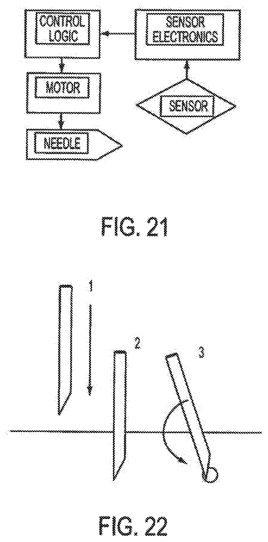
D00013

D00014

D00015
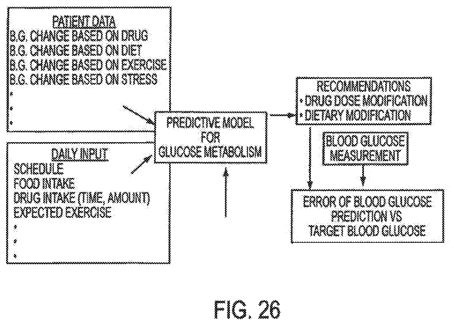
D00016
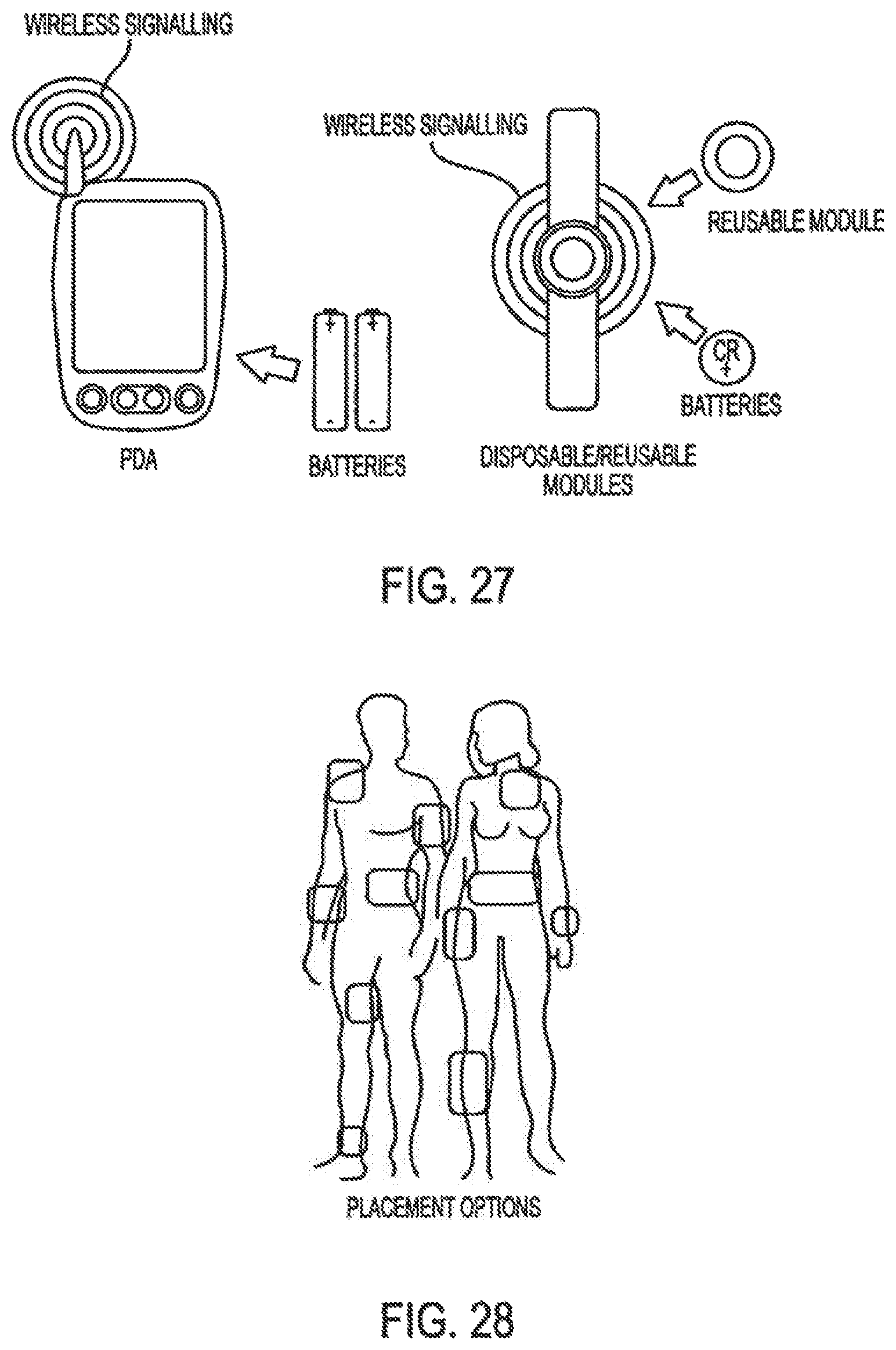
D00017

D00018

D00019

D00020
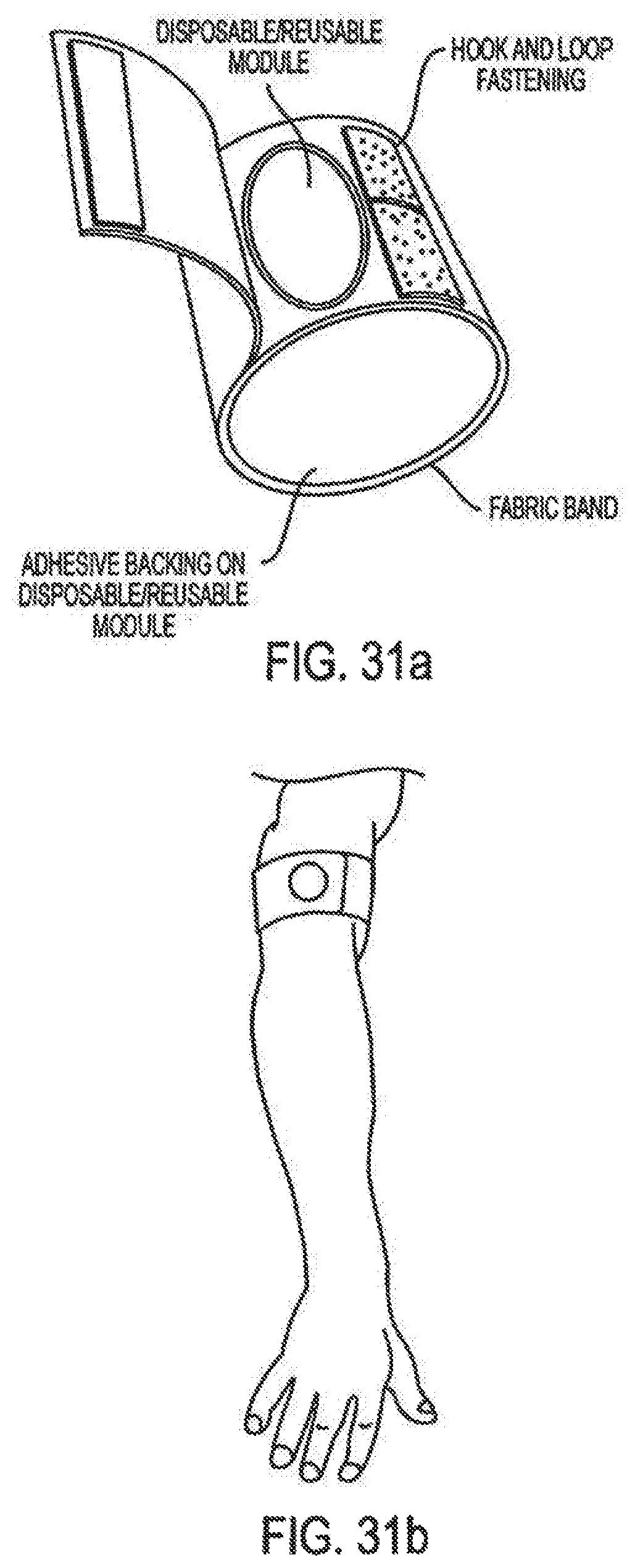
D00021
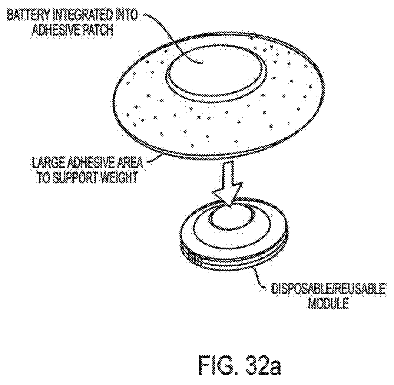
D00022

D00023

D00024
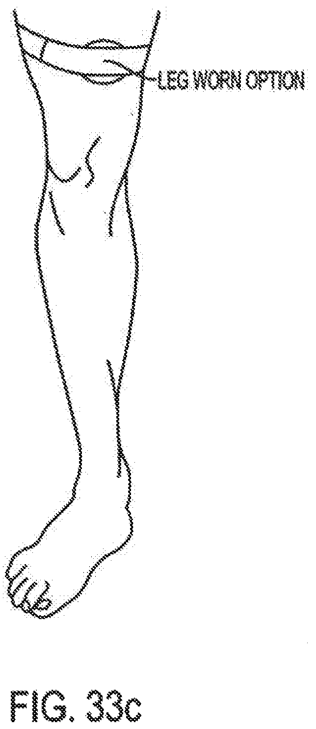
D00025

D00026
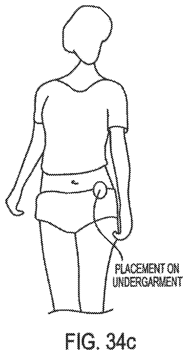
XML
uspto.report is an independent third-party trademark research tool that is not affiliated, endorsed, or sponsored by the United States Patent and Trademark Office (USPTO) or any other governmental organization. The information provided by uspto.report is based on publicly available data at the time of writing and is intended for informational purposes only.
While we strive to provide accurate and up-to-date information, we do not guarantee the accuracy, completeness, reliability, or suitability of the information displayed on this site. The use of this site is at your own risk. Any reliance you place on such information is therefore strictly at your own risk.
All official trademark data, including owner information, should be verified by visiting the official USPTO website at www.uspto.gov. This site is not intended to replace professional legal advice and should not be used as a substitute for consulting with a legal professional who is knowledgeable about trademark law.