Protective case for use with device grip
Peterson , et al. A
U.S. patent number 10,750,844 [Application Number 16/275,969] was granted by the patent office on 2020-08-25 for protective case for use with device grip. This patent grant is currently assigned to Otter Products, LLC. The grantee listed for this patent is Otter Products, LLC. Invention is credited to Alyson J. Beck, Jamie L. Johnson, Joshua K. Peterson, Dustin S. Rodriguez.


View All Diagrams
| United States Patent | 10,750,844 |
| Peterson , et al. | August 25, 2020 |
Protective case for use with device grip
Abstract
A protective case system includes an extendable device grip and a protective case. The extendable device grip includes an attachment mechanism and has a stowed configuration and extended configuration. The protective case includes a shell and a receiver. The shell is configured for receiving and removably retaining an electronic device. The shell has at least a back wall and side walls. The outer surface of the back wall of the shell includes a recessed or concave area. The extendable device grip is removably attachable to the receiver for removably attaching the extendable device grip to the protective case. The receiver is positioned in the recessed or concave area of the back wall of the shell such that at least a portion of the extendable device grip is within the recessed area when the extendable device grip is attached to the protective case and is in the stowed configuration.
| Inventors: | Peterson; Joshua K. (Fort Collins, CO), Johnson; Jamie L. (Fort Collins, CO), Beck; Alyson J. (Fort Collins, CO), Rodriguez; Dustin S. (Fort Collins, CO) | ||||||||||
|---|---|---|---|---|---|---|---|---|---|---|---|
| Applicant: |
|
||||||||||
| Assignee: | Otter Products, LLC (Fort
Collins, CO) |
||||||||||
| Family ID: | 67904655 | ||||||||||
| Appl. No.: | 16/275,969 | ||||||||||
| Filed: | February 14, 2019 |
Prior Publication Data
| Document Identifier | Publication Date | |
|---|---|---|
| US 20190281960 A1 | Sep 19, 2019 | |
Related U.S. Patent Documents
| Application Number | Filing Date | Patent Number | Issue Date | ||
|---|---|---|---|---|---|
| 62782919 | Dec 20, 2018 | ||||
| 62663316 | Apr 27, 2018 | ||||
| 62643429 | Mar 15, 2018 | ||||
| Current U.S. Class: | 1/1 |
| Current CPC Class: | A45C 11/00 (20130101); A45F 5/00 (20130101); A45F 2200/0516 (20130101); A45C 2011/001 (20130101); A45F 2200/0508 (20130101); A45C 2011/003 (20130101); A45F 2005/008 (20130101); A45F 2200/0525 (20130101); A45C 2011/002 (20130101); A45C 2200/15 (20130101) |
| Current International Class: | A45F 5/00 (20060101); A45C 11/00 (20060101) |
References Cited [Referenced By]
U.S. Patent Documents
| 3023885 | March 1962 | Kindseth |
| 3480310 | November 1969 | Mcelwain |
| 3521216 | July 1970 | Tolegian |
| 3786391 | January 1974 | Mathauser |
| 3808577 | April 1974 | Mathauser |
| 3810258 | May 1974 | Mathauser |
| 3816679 | June 1974 | Hotchkiss |
| 4029999 | June 1977 | Neumann et al. |
| 4097878 | June 1978 | Cramer |
| 4182558 | January 1980 | Matsuo |
| 4431333 | February 1984 | Chandler |
| 4584718 | April 1986 | Fuller |
| 4856658 | August 1989 | Novak |
| 4859110 | August 1989 | Dommel |
| 4925146 | May 1990 | Hegarty |
| 4933988 | June 1990 | Thibault |
| 4940414 | July 1990 | Lee |
| 4963902 | October 1990 | Fukahori |
| 4981243 | January 1991 | Rogowski |
| 4994829 | February 1991 | Tsukamoto |
| 5025921 | June 1991 | Gasparaitis et al. |
| 5054733 | October 1991 | Shields |
| 5123044 | June 1992 | Tate |
| 5138523 | August 1992 | Benck et al. |
| 5359756 | November 1994 | Miyauchi et al. |
| 5360108 | November 1994 | Alagia |
| 5368159 | November 1994 | Doria |
| 5380968 | January 1995 | Morse |
| 5383091 | January 1995 | Snell |
| 5386084 | January 1995 | Risko |
| 5388691 | February 1995 | White |
| 5388692 | February 1995 | Withrow et al. |
| D365927 | January 1996 | Cho |
| 5508479 | April 1996 | Schooley |
| 5541813 | July 1996 | Satoh et al. |
| 5604050 | February 1997 | Brunette et al. |
| 5664292 | September 1997 | Chen |
| 5671120 | September 1997 | Kikinisi |
| 5992807 | November 1999 | Tarulli |
| 5996956 | December 1999 | Shawver |
| 6097593 | August 2000 | Faranda et al. |
| 6115248 | September 2000 | Canova et al. |
| 6135408 | October 2000 | Richter |
| 6149116 | November 2000 | Won |
| 6151206 | November 2000 | Kato et al. |
| 6302617 | October 2001 | Rumpp |
| 6305588 | October 2001 | Michel et al. |
| 6305656 | October 2001 | Wemyss |
| 6311017 | October 2001 | Mori |
| 6317313 | November 2001 | Mosgrove et al. |
| 6349824 | February 2002 | Yamada |
| 6375009 | April 2002 | Lee |
| 6409531 | June 2002 | Millard |
| 6445577 | September 2002 | Madsen et al. |
| 6456487 | September 2002 | Hetterick |
| 6464524 | October 2002 | Kerr et al. |
| 6490155 | December 2002 | Han et al. |
| 6514624 | February 2003 | Takemoto |
| 6545862 | April 2003 | Gettemy et al. |
| 6616111 | September 2003 | White |
| 6625394 | September 2003 | Smith et al. |
| 6626362 | September 2003 | Steiner et al. |
| 6646864 | November 2003 | Richardson |
| 6685493 | February 2004 | Birkenmaier et al. |
| 6701159 | March 2004 | Powell |
| 6705580 | March 2004 | Bain |
| 6762935 | July 2004 | Hidewasa |
| 6865076 | March 2005 | Lunsford |
| 6888940 | May 2005 | Deppen |
| 6966519 | November 2005 | Salentine et al. |
| 7050841 | May 2006 | Onda |
| 7072699 | July 2006 | Eiden |
| D526780 | August 2006 | Richardson et al. |
| 7145767 | December 2006 | Mache et al. |
| 7158376 | January 2007 | Richardson et al. |
| 7180735 | February 2007 | Thomas et al. |
| 7194291 | March 2007 | Peng |
| D542524 | May 2007 | Richardson et al. |
| 7230823 | June 2007 | Richardson et al. |
| 7236588 | June 2007 | Gartrell |
| 7287738 | October 2007 | Pitlor |
| 7311526 | December 2007 | Rohrbach et al. |
| 7343184 | March 2008 | Rostami |
| 7359184 | April 2008 | Lord |
| 7374142 | May 2008 | Carnevali |
| D574819 | August 2008 | Andre et al. |
| 7431251 | October 2008 | Carnevali |
| D581155 | November 2008 | Richardson et al. |
| D581421 | November 2008 | Richardson et al. |
| D587008 | February 2009 | Richardson et al. |
| D589016 | March 2009 | Richardson et al. |
| 7555325 | June 2009 | Goros |
| 7558594 | July 2009 | Wilson |
| 7575389 | August 2009 | Nance |
| 7661567 | February 2010 | Myers |
| 7688580 | March 2010 | Richardson et al. |
| 7845608 | December 2010 | Chen et al. |
| 7871218 | January 2011 | Frey et al. |
| 7889489 | February 2011 | Richardson et al. |
| 7907394 | March 2011 | Richardson et al. |
| 7933122 | April 2011 | Richardson et al. |
| 8016107 | September 2011 | Emsky |
| 8049727 | November 2011 | Hanson et al. |
| 8204561 | June 2012 | Mongan et al. |
| 8303336 | November 2012 | Smith |
| 8442604 | May 2013 | Diebel |
| 8453344 | June 2013 | Nishiwaki et al. |
| 8453835 | June 2013 | So |
| 8457701 | June 2013 | Diebel |
| 8490783 | July 2013 | Fan |
| 8509865 | August 2013 | LaColla et al. |
| 8514568 | August 2013 | Qiao et al. |
| 8560031 | October 2013 | Barnett |
| 8567599 | October 2013 | Beatty et al. |
| 8599547 | December 2013 | Richardson et al. |
| 8608502 | December 2013 | Witter et al. |
| 8646739 | February 2014 | Moyer |
| 8676281 | March 2014 | Caulder et al. |
| 8706175 | April 2014 | Cho |
| 8737066 | May 2014 | Block |
| 8755852 | June 2014 | Hynecek et al. |
| 8770402 | July 2014 | Bergreen et al. |
| 8777002 | July 2014 | Thomas et al. |
| 8798675 | August 2014 | Salmon et al. |
| 8800762 | August 2014 | Fathollahi |
| 8830663 | September 2014 | Child et al. |
| 8844098 | September 2014 | Karmatz |
| 8875879 | November 2014 | Diebel et al. |
| D722603 | February 2015 | Lay et al. |
| 8955678 | February 2015 | Murphy et al. |
| 8965458 | February 2015 | Richardson et al. |
| D725119 | March 2015 | Gaylord |
| D726732 | April 2015 | Lay et al. |
| 9008738 | April 2015 | Dong |
| 9060580 | June 2015 | Tages |
| 9089056 | July 2015 | Rayner |
| 9098238 | August 2015 | Richardson et al. |
| D739857 | September 2015 | Lay et al. |
| 9125297 | September 2015 | Magness |
| 9136897 | September 2015 | Hynecek et al. |
| 9153112 | October 2015 | Kiani et al. |
| 9226057 | December 2015 | Davis et al. |
| 9266664 | February 2016 | Bau |
| 9274556 | March 2016 | Gallouzi et al. |
| 9295174 | March 2016 | Witter et al. |
| 9301584 | April 2016 | Butts |
| 9316026 | April 2016 | Myers et al. |
| 9316344 | April 2016 | Le Gette |
| 9367090 | June 2016 | Barnett et al. |
| 9377154 | June 2016 | Hung et al. |
| D762258 | July 2016 | Jenkins |
| 9397719 | July 2016 | Schmidt |
| 9408448 | August 2016 | Kay et al. |
| D766226 | September 2016 | Wu |
| D766227 | September 2016 | Wu |
| D769855 | October 2016 | Deng |
| 9462099 | October 2016 | Wilson |
| 9470358 | October 2016 | Le Gette |
| 9481490 | November 2016 | Venida et al. |
| 9487376 | November 2016 | Salentine et al. |
| 9503147 | November 2016 | Witter et al. |
| D775115 | December 2016 | Ormsbee et al. |
| 9537526 | January 2017 | Wilson et al. |
| 9538675 | January 2017 | Le Gette |
| 9545140 | January 2017 | Johnson et al. |
| 9615476 | April 2017 | Rayner et al. |
| 9622556 | April 2017 | Fathollahi et al. |
| 9654605 | May 2017 | Goldfain et al. |
| 9660684 | May 2017 | Rayner |
| 9743540 | August 2017 | Magness |
| 9765921 | September 2017 | Vogel et al. |
| 9774713 | September 2017 | Guerdrum et al. |
| D799469 | October 2017 | Esses |
| 9788620 | October 2017 | Parkinson |
| 9800283 | October 2017 | Schmidt |
| 9806549 | October 2017 | Liberti |
| 9807211 | October 2017 | Guerdrum et al. |
| 9851758 | December 2017 | Rowley |
| D808376 | January 2018 | Kim |
| D808377 | January 2018 | Witter et al. |
| 9871550 | January 2018 | Witter et al. |
| 9913388 | March 2018 | Mchatet |
| 9930943 | April 2018 | Lach |
| D824376 | July 2018 | Lee |
| 10019034 | July 2018 | Barnett |
| 10027783 | July 2018 | Dukerschein et al. |
| 10030807 | July 2018 | Hobbs |
| 10054259 | August 2018 | Hobbs |
| 10058155 | August 2018 | Guerdrum et al. |
| 10060573 | August 2018 | Hobbs |
| D827627 | September 2018 | Lee |
| D829700 | October 2018 | Kim |
| 10103769 | October 2018 | Witter et al. |
| 10136716 | November 2018 | Northrup et al. |
| D835091 | December 2018 | Torrance |
| 10178903 | January 2019 | Guerdrum et al. |
| 10200518 | February 2019 | Richter |
| 10206472 | February 2019 | Northrup et al. |
| 10244854 | April 2019 | Haber |
| 10278299 | April 2019 | Kim |
| D847805 | May 2019 | Lederer |
| 10348352 | July 2019 | Barnett |
| 10386009 | August 2019 | Hobbs |
| 10389860 | August 2019 | Nahum |
| 10413027 | September 2019 | Olson |
| D864581 | October 2019 | Bersh |
| 10463116 | November 2019 | Barnett |
| D870736 | December 2019 | Lederer |
| 10530411 | January 2020 | Gehlhausen |
| 2001/0000617 | May 2001 | Tracy |
| 2001/0054594 | December 2001 | Maier-Hunke |
| 2002/0065054 | May 2002 | Humphreys et al. |
| 2002/0079244 | June 2002 | Kwong |
| 2003/0141329 | July 2003 | Huang |
| 2004/0029405 | February 2004 | Neidlein |
| 2004/0150945 | August 2004 | Mache et al. |
| 2005/0088811 | April 2005 | Ulla et al. |
| 2005/0213298 | September 2005 | Doherty et al. |
| 2005/0224508 | October 2005 | Tajiri et al. |
| 2005/0279661 | December 2005 | Hodges |
| 2005/0284904 | December 2005 | Knapp et al. |
| 2006/0027718 | February 2006 | Quijano et al. |
| 2006/0066438 | March 2006 | Altounian et al. |
| 2006/0086873 | April 2006 | Chen |
| 2006/0172765 | August 2006 | Lev |
| 2006/0237495 | October 2006 | Chen et al. |
| 2006/0243679 | November 2006 | Dickerson |
| 2006/0255493 | November 2006 | Fouladpour |
| 2007/0071423 | March 2007 | Fantone et al. |
| 2007/0115387 | May 2007 | Ho |
| 2007/0146985 | June 2007 | Mick et al. |
| 2007/0155448 | July 2007 | Hong |
| 2007/0158220 | July 2007 | Cleereman et al. |
| 2007/0181620 | August 2007 | Carver, III |
| 2007/0215659 | September 2007 | Knapp et al. |
| 2007/0215769 | September 2007 | Nebeker et al. |
| 2007/0297149 | December 2007 | Richardson et al. |
| 2008/0083797 | April 2008 | Myers |
| 2008/0117578 | May 2008 | Moscovitch |
| 2008/0163463 | July 2008 | Hulden |
| 2008/0199252 | August 2008 | Frey et al. |
| 2008/0304692 | December 2008 | Zhang |
| 2009/0001232 | January 2009 | Seo et al. |
| 2009/0034169 | February 2009 | Richardson et al. |
| 2009/0079665 | March 2009 | Moscovitch |
| 2009/0084705 | April 2009 | Justiss |
| 2009/0161903 | June 2009 | White |
| 2009/0237377 | September 2009 | Lai et al. |
| 2009/0283184 | November 2009 | Han |
| 2010/0006468 | January 2010 | Lin |
| 2010/0078343 | April 2010 | Hoellwarth et al. |
| 2010/0090085 | April 2010 | Corrion |
| 2010/0093412 | April 2010 | Serra et al. |
| 2010/0122756 | May 2010 | Longinotti-Buitoni |
| 2010/0141864 | June 2010 | Lai |
| 2010/0147737 | June 2010 | Richardson et al. |
| 2010/0181450 | July 2010 | Hulick et al. |
| 2010/0195279 | August 2010 | Michael |
| 2010/0203931 | August 2010 | Hynecek et al. |
| 2010/0215188 | August 2010 | Wilcox |
| 2010/0230301 | September 2010 | Fellig |
| 2011/0031287 | February 2011 | Gette et al. |
| 2011/0064401 | March 2011 | DeSorbo |
| 2011/0073505 | March 2011 | Stiehl |
| 2011/0073608 | March 2011 | Richardson et al. |
| 2011/0075349 | March 2011 | Ma et al. |
| 2011/0101058 | May 2011 | Heckman |
| 2011/0170256 | July 2011 | Lee |
| 2011/0192857 | August 2011 | Rothbaum et al. |
| 2011/0216495 | September 2011 | Marx |
| 2011/0228459 | September 2011 | Richardson et al. |
| 2011/0235846 | September 2011 | Jiang et al. |
| 2011/0294556 | December 2011 | Carlberg et al. |
| 2011/0297566 | December 2011 | Gallagher et al. |
| 2011/0314651 | December 2011 | Behar et al. |
| 2012/0018325 | January 2012 | Kim |
| 2012/0031788 | February 2012 | Mongan |
| 2012/0037524 | February 2012 | Thomas et al. |
| 2012/0037536 | February 2012 | Thomas et al. |
| 2012/0043235 | February 2012 | Klement |
| 2012/0074005 | March 2012 | Johnson et al. |
| 2012/0092377 | April 2012 | Stein |
| 2012/0106069 | May 2012 | Strauser |
| 2012/0111881 | May 2012 | Gaddis et al. |
| 2012/0118770 | May 2012 | Valls |
| 2012/0170194 | July 2012 | Lord et al. |
| 2012/0175474 | July 2012 | Barnard et al. |
| 2012/0187260 | July 2012 | Moyer |
| 2012/0252543 | October 2012 | Cho |
| 2012/0267491 | October 2012 | Chiu |
| 2012/0287565 | November 2012 | Bennett |
| 2012/0325702 | December 2012 | Gallagher et al. |
| 2012/0326003 | December 2012 | Solow et al. |
| 2013/0027862 | January 2013 | Rayner |
| 2013/0039521 | February 2013 | Zhou et al. |
| 2013/0068915 | March 2013 | Yang |
| 2013/0083953 | April 2013 | Chang |
| 2013/0088813 | April 2013 | Su et al. |
| 2013/0098788 | April 2013 | McCarville et al. |
| 2013/0107449 | May 2013 | Su et al. |
| 2013/0109253 | May 2013 | Gammon et al. |
| 2013/0117487 | May 2013 | Leung |
| 2013/0126533 | May 2013 | Klosky |
| 2013/0175186 | July 2013 | Simmer |
| 2013/0177181 | July 2013 | Marcus |
| 2013/0181584 | July 2013 | Whitten et al. |
| 2013/0220841 | August 2013 | Yang |
| 2013/0220847 | August 2013 | Fisher et al. |
| 2013/0222989 | August 2013 | Chen |
| 2013/0230202 | September 2013 | Widner et al. |
| 2013/0240578 | September 2013 | Yu |
| 2013/0262248 | October 2013 | Kim et al. |
| 2013/0292269 | November 2013 | Tages |
| 2013/0292288 | November 2013 | Willes |
| 2013/0303000 | November 2013 | Witter et al. |
| 2013/0318775 | December 2013 | Peters |
| 2014/0003647 | January 2014 | Liu |
| 2014/0049142 | February 2014 | Magness |
| 2014/0065847 | March 2014 | Salmon et al. |
| 2014/0080553 | March 2014 | Torset et al. |
| 2014/0097102 | April 2014 | Piatt et al. |
| 2014/0099526 | April 2014 | Powell |
| 2014/0128132 | May 2014 | Cox |
| 2014/0141838 | May 2014 | Cai et al. |
| 2014/0152890 | June 2014 | Rayner |
| 2014/0166707 | June 2014 | Leisey-Bartsch |
| 2014/0168884 | June 2014 | Wylie |
| 2014/0183064 | July 2014 | Ge |
| 2014/0183065 | July 2014 | Toulotte |
| 2014/0187289 | July 2014 | Cataldo et al. |
| 2014/0200056 | July 2014 | Liu |
| 2014/0227026 | August 2014 | O'Neill et al. |
| 2014/0228074 | August 2014 | Kulkarni et al. |
| 2014/0262848 | September 2014 | Fathollahi et al. |
| 2014/0262934 | September 2014 | Fathollahi et al. |
| 2014/0265765 | September 2014 | Khodapanah et al. |
| 2014/0265767 | September 2014 | Fathollahi |
| 2014/0299488 | October 2014 | Andrew |
| 2014/0302896 | October 2014 | Xu et al. |
| 2014/0325818 | November 2014 | Mayfield |
| 2014/0355200 | December 2014 | Thiers |
| 2015/0061477 | March 2015 | Wilson |
| 2015/0062787 | March 2015 | Wilson et al. |
| 2015/0068935 | March 2015 | Kay et al. |
| 2015/0083615 | March 2015 | Lay et al. |
| 2015/0111623 | April 2015 | Hegemier et al. |
| 2015/0133183 | May 2015 | Alameh et al. |
| 2015/0141090 | May 2015 | Hwan et al. |
| 2015/0141095 | May 2015 | Kim |
| 2015/0153791 | June 2015 | Wong |
| 2015/0172431 | June 2015 | Huang |
| 2015/0189160 | July 2015 | Auger et al. |
| 2015/0194997 | July 2015 | Johnson et al. |
| 2015/0194998 | July 2015 | Fathollahi |
| 2015/0195938 | July 2015 | Witter et al. |
| 2015/0201723 | July 2015 | Rayner et al. |
| 2015/0214989 | July 2015 | Yeh et al. |
| 2015/0220766 | August 2015 | Russell et al. |
| 2015/0257285 | September 2015 | Wilson et al. |
| 2015/0257287 | September 2015 | Tages |
| 2015/0304466 | October 2015 | Tamatsu |
| 2015/0335138 | November 2015 | Juarbe |
| 2016/0007705 | January 2016 | Liebers et al. |
| 2016/0036478 | February 2016 | Wong |
| 2016/0040825 | February 2016 | Franklin |
| 2016/0045005 | February 2016 | Richardson |
| 2016/0072933 | March 2016 | Cox |
| 2016/0080024 | March 2016 | Wilson et al. |
| 2016/0122821 | May 2016 | Liu et al. |
| 2016/0142093 | May 2016 | Phang |
| 2016/0150861 | June 2016 | Yao et al. |
| 2016/0164565 | June 2016 | Witter et al. |
| 2016/0179143 | June 2016 | Bidwell et al. |
| 2016/0183392 | June 2016 | Kelley |
| 2016/0195898 | July 2016 | Lau |
| 2016/0198822 | July 2016 | Lee et al. |
| 2016/0254836 | September 2016 | Alsberg et al. |
| 2016/0261133 | September 2016 | Wang |
| 2016/0282905 | September 2016 | Laine et al. |
| 2016/0286920 | October 2016 | Lean et al. |
| 2016/0286921 | October 2016 | Northrup et al. |
| 2016/0295981 | October 2016 | Lay et al. |
| 2016/0347257 | December 2016 | Buchanan |
| 2017/0026498 | January 2017 | Goldfain et al. |
| 2017/0041037 | February 2017 | Witter et al. |
| 2017/0099922 | April 2017 | Guerdrum et al. |
| 2017/0099924 | April 2017 | Fathollahi et al. |
| 2017/0119120 | May 2017 | Richardson et al. |
| 2017/0195000 | July 2017 | Srour |
| 2017/0237460 | August 2017 | Rayner |
| 2017/0279478 | September 2017 | Fathollahi |
| 2017/0327054 | November 2017 | Yu et al. |
| 2017/0328517 | November 2017 | Wessels |
| 2017/0353208 | December 2017 | Wilson et al. |
| 2017/0359096 | December 2017 | Witter et al. |
| 2017/0360200 | December 2017 | Cohen |
| 2018/0013463 | January 2018 | Jeon |
| 2018/0101197 | April 2018 | Barnett |
| 2018/0136695 | May 2018 | Lo et al. |
| 2018/0167498 | June 2018 | Drakos |
| 2018/0369599 | December 2018 | Smith |
| 2019/0094853 | March 2019 | Overall |
| 2019/0141848 | May 2019 | Sung |
| 2019/0208046 | July 2019 | Gluck |
| 2019/0211966 | July 2019 | Nahum |
| 2019/0212774 | July 2019 | Patterson et al. |
| 2019/0215387 | July 2019 | Chiang |
| 2019/0222682 | July 2019 | Ren et al. |
| 2019/0225378 | July 2019 | Barnett |
| 2019/0229763 | July 2019 | Nebel et al. |
| 2019/0243421 | August 2019 | Barnett |
| 2019/0245960 | August 2019 | Nahum |
| 2019/0250664 | August 2019 | Eslava et al. |
| 2019/0278327 | September 2019 | Barnett |
| 2019/0278328 | September 2019 | Barnett |
| 2019/0281147 | September 2019 | Sherburne et al. |
| 2019/0281960 | September 2019 | Peterson |
| 2019/0281961 | September 2019 | Peterson |
| 2019/0286191 | September 2019 | Correll, Jr. |
| 2019/0335030 | October 2019 | Nahum |
| 2019/0335031 | October 2019 | Nahum |
| 202488509 | Oct 2012 | CN | |||
| 935529 | Jun 1948 | FR | |||
| 200446444 | Oct 2009 | KR | |||
| 101394285 | May 2014 | KR | |||
| 1994000037 | Jan 1994 | WO | |||
| 1999041958 | Aug 1999 | WO | |||
| 2015103599 | Jul 2015 | WO | |||
Other References
|
Outfityours.com (Top 5 Best Clear iPhone 5S and iPhone 5 Cases--Incase, Otterbox, Griffin, Moshi [retrieved from https://www.youtube.com/watch?v=rWYKJvsDHPw], YouTube.com [online], May 17, 2013 [retrieved Oct. 11, 2017}, 3 pages. cited by applicant . Randomrazr (New Otterbox Symmetry Case--The Slim Protective Case for the iPhone 5S/5C [retrieved from https://wwwyoutube.com/watch?v=zGWZTGamuT0], YouTube.com [online], Mar. 30, 2014 [retrieved Oct. 11, 2017]), 5 pages. cited by applicant . Otterbox, "OtterBox and PopSockets Announce Swappable, Unstoppable Otter+Pop," dated Jan. 7, 2019, downloaded from http://media.otterbox.com/2019-01-07-OtterBox-and-PopSockets-Announce-Swa- ppable-Unstoppable-Otter-Pop Jul. 3, 2019. cited by applicant . Otterbox, "Swappable, Unstoppable: OtterBox and PopSockets Cases Available Now," dated Mar. 26, 2019, downloaded from http://media.otterbox.com/2019-03-26-Swappable-Unstoppable-OtterBox-and-P- opSockets-Cases-Available-Now Jul. 3, 2019. cited by applicant. |
Primary Examiner: Larson; Justin M
Parent Case Text
CROSS REFERENCE TO RELATED APPLICATIONS
The present application claims priority to U.S. Provisional Patent Application No. 62/782,919, filed Dec. 20, 2018, U.S. Provisional Patent Application No. 62/663,316, filed Apr. 27, 2018, and U.S. Provisional Patent Application No. 62/643,429, filed Mar. 15, 2018, each of which is incorporated by reference in its entirety.
Claims
What is claimed is:
1. A protective case system for use with an electronic device, the protective case system comprising: an extendable device grip having an attachment mechanism, the extendable device grip having a stowed configuration and extended configuration, wherein the extendable device grip is configured to be transitioned between the stowed configuration and the extended configuration by a user; and a protective case comprising: a shell configured for receiving and removably retaining the electronic device, the shell having at least a back wall and side walls, the back and side walls of the shell configured to cover at least a portion of the electronic device when the electronic device is installed in the shell, wherein an outer surface of the back wall of the shell includes a recessed area, and wherein the side walls are configured to provide a water-resistant seal to the installed electronic device; and a receiver to which the attachment mechanism of the extendable device grip is removably attachable for removably attaching the extendable device grip to the protective case, wherein the receiver is positioned in the recessed area of the outer surface of the back wall of the shell such that at least a portion of the extendable device grip is within the recessed area when the extendable device grip is attached to the protective case and is in the stowed configuration, wherein a perimeter of the extendable device grip contacts a perimeter of the recessed area of the outer surface of the back wall of the shell to form a water-resistant seal when the extendable grip device is in the stowed configuration.
2. The protective case system of claim 1 wherein the attachment mechanism of the extendable device grip is rotatably attachable to the receiver of the protective case.
3. The protective case system of claim 1 wherein the extendable device grip includes a collapsible tapered accordion structure for transitioning the extendable device grip between the extended configuration and the stowed configuration.
4. The protective case system of claim 1 wherein one or both of the receiver and the attachment mechanism include a snap retention feature for retaining the extendable device grip to the protective case.
5. The protective case system of claim 1 wherein both the extendable device grip and the recessed area of the shell have round shapes.
6. The protective case system of claim 1 wherein the entire extendable device grip is within the recessed area when the extendable device grip is attached to the protective case and is in the stowed configuration.
7. The protective case system of claim 1 wherein a gap is present between a rim of the recessed area and a top edge of the extendable device grip when the extendable device grip is attached to the protective case and is in the stowed configuration.
8. A protective case system for use with an electronic device, the protective case system comprising: an extendable device grip having an attachment mechanism, the extendable device grip having a stowed configuration and extended configuration; and protective case comprising: a shell configured for receiving and removably retaining the electronic device, the shell having at least a back wall and side walls, the back and side walls of the shell configured to cover at least a portion of the electronic device when the electronic device is removably installed in the shell, wherein an outer surface of the back wall of the shell includes a concave area; and a receiver to which the extendable device grip is rotatably attachable for removably attaching the extendable device grip to the protective case, wherein the receiver is positioned in the concave area of the outer surface of the back wall of the shell such that the extendable device grip is substantially within the concave area of the shell when the extendable device grip is attached to the protective case and is in the stowed configuration, wherein the concave area of the shell includes a recess at one location on a perimeter of the concave area, the recess configured for receiving a human fingernail for facilitating extension of the extendable device grip from the recessed area and from the stowed configuration to the extended configuration, and wherein the extendable device grip contacts the perimeter of the concave area of the shell to form a water-resistant seal with the shell when the extendable device grip is in the stowed configuration.
9. The protective case system of claim 8 wherein the receiver is permanently affixed to the shell.
10. The protective case system of claim 8 wherein the receiver is molded into the shell.
11. The protective case system of claim 8 wherein the outer surface of the back wall of the shell slopes upward from the sides walls to a rim of the concave area.
12. The protective case system of claim 8 wherein the receiver includes a snap retention feature having an interference fit with the attachment mechanism of the extendable device grip for removably retaining the extendable device grip.
13. The protective case system of claim 8 further comprising an inner cushioning liner affixed to an interior surface of the shell.
14. A protective case system for use with an electronic device, the protective case system comprising: an extendable device grip configured for assisting a user in holding the electronic device; and a protective case comprising: a body configured for receiving and removably retaining the electronic device, the body having at least a back wall and side walls, the back and side walls configured to cover at least a portion of the electronic device when the electronic device is installed in the body; and a grip aperture extending through the back wall of the body, the grip aperture having a size and a shape adapted to permit direct attachment of the device grip to a back surface of the installed electronic device through the grip aperture, wherein the back wall of the body has a contoured shape configured such that an edge of the grip aperture is adjacent to the distal end of the device grip and forms a water-resistant seal with the device grip when the device grip is attached to the installed electronic device and is in a storage position.
15. The protective case system of claim 14 wherein an envelope thickness of the protective case at one or more of the sidewalls is less than an envelope thickness of the body at the grip aperture.
16. The protective case system of claim 14 wherein the back of the body includes an outer surface and the contoured shape of the outer surface includes a sloped region between the outer edge of the grip aperture and one or more of the side walls.
17. The protective case system of claim 14 wherein the protective case includes a notch configured for receiving a fingernail for facilitating the extension of the extendable device grip from the storage position to a use position.
18. A protective case for use with an electronic device and a device grip, the protective case comprising: a body adapted for receiving and removably retaining the electronic device, the body having at least a back wall and side walls, the back and side walls adapted to cover at least a portion of the electronic device when the electronic device is installed in the body, wherein the body is configured to provide a water-proof seal to the installed electronic device; and a grip aperture extending through the back wall of the body, the grip aperture having a size and a shape adapted to facilitate direct attachment of the device grip to a back surface of the installed electronic device through the grip aperture, wherein the back wall of the body has a non-planar shape and an outer edge of the grip aperture is adapted to contact the distal end of the device grip and form a water-resistant seal with the device grip when the device grip is attached to the installed electronic device and is in a storage position.
19. The protective case of claim 18 wherein the outer edge of the grip aperture is flush with the distal end of the device grip when the device grip is attached to the installed electronic device and is in the storage position.
20. The protective case of claim 18 further including an outer cushion layer adapted to be removably installed over at least a portion of the body of the protective case, wherein the outer cushion layer includes an aperture that coincides with the grip aperture.
Description
BACKGROUND
Electronic devices, particularly portable electronic devices, are used for a growing variety of purposes, as well as in a growing variety of situations. Examples of portable electronic devices include smartphones, tablet computers, gaming devices, audio players, video players, cameras, portable computers, two-way radios, GPS receivers, and/or other portable devices. Portable electronic devices are susceptible to damage from a variety or forces or elements such as dropping, impact, and scratching. At the same time the cost of portable electronic devices is increasing. Improved apparatuses and techniques for protecting and holding portable and personal electronic devices are needed for better accommodating these changing use models.
SUMMARY
In one exemplary embodiment, a protective case system for use with an electronic device includes an extendable device grip and a protective case. The extendable device grip includes an attachment mechanism and has a stowed configuration and extended configuration. The extendable device grip is configured to be transitioned between the stowed configuration and the extended configuration by a user. The protective case includes a shell and a receiver. The shell is configured for receiving and removably retaining the electronic device. The shell has at least a back wall and side walls. The back and side walls of the shell are configured to cover at least a portion of the electronic device when the electronic device is installed in the shell. The outer surface of the back wall of the shell includes a recessed or concave area. The extendable device grip is removably attachable to the receiver of the shell for removably attaching the extendable device grip to the protective case. The receiver is positioned in the recessed or concave area of the outer surface of the back wall of the shell such that at least a portion of the extendable device grip is within the recessed area when the extendable device grip is attached to the protective case and is in the stowed configuration. In some embodiments, only one of the protective case and extendable device grip may be included.
In another embodiment, a protective case is configured for use with an electronic device and with a device grip. The protective case includes a body configured for receiving and removably retaining the electronic device. The body has at least a back wall and side walls which are configured to cover at least a portion of the electronic device when the electronic device is installed in the body. The protective case also includes a grip aperture extending through the back wall of the body. The grip aperture has a size and/or a shape adapted to permit direct attachment of the device grip to a back surface of the installed electronic device through the grip aperture. A thickness of the back wall proximate the grip aperture is greater than thicknesses of other portions of the back wall such that an outer surface of the back wall is approximately flush with an end of the device grip when the device grip is attached to the installed electronic device and is in a non-extended position.
In another embodiment, a protective case is configured for use with an electronic device and a device grip. The protective case includes a body configured for receiving and removably retaining the electronic device. The body has at least a back and side walls configured to cover at least a portion of the electronic device when the electronic device is installed in the body. The protective case also includes a grip aperture extending through the back wall of the body. The grip aperture has a size and a shape adapted to permit direct attachment of the device grip to a back surface of the installed electronic device through the grip aperture. An outer surface of the back wall of the body is non-planar such that the outer surface of the back wall is approximately flush with an end of the device grip when the device grip is attached to the installed electronic device and is in a non-extended position.
In yet another embodiment, a protective case or cover is adapted for use with an electronic device and a device grip. The device grip has a proximal end and a distal end. The protective case or cover includes a body adapted for receiving and removably retaining the electronic device. The body has at least a back wall and side wall. The back and side walls are adapted to cover at least a portion of the electronic device when the electronic device is installed in the body. A grip aperture extends through the back wall of the body, the grip aperture is adapted to permit direct attachment of the proximal end of the device grip to a back surface of the installed electronic device through the grip aperture. An outer surface of the back wall of the body has a non-planar shape or contour and is adapted such that an outer edge of the grip aperture is proximate the distal end of the device grip when the device grip is attached to the installed electronic device and is in a storage position.
In a further embodiment, a protective case system for use with an electronic device includes a device grip and a protective case. The device grip is configured to be attachable to a back of the electronic device. The device grip is extendable and configured for facilitating holding of the electronic device when attached to the electronic device. The protective case includes a body and a grip aperture. The body is configured for receiving and removably retaining the electronic device. The body has at least a back and side walls. The back and side walls are configured to cover at least a portion of the electronic device when the electronic device is installed in the body. The grip aperture extends through the back wall of the body. The grip aperture has a size and a shape adapted to permit direct attachment of the device grip to a back surface of the installed electronic device through the grip aperture. The outer surface of the back wall of the body is non-planar such that the outer surface of the back wall is approximately flush with an end of the device grip when the device grip is attached to the installed electronic device and is in a non-extended position.
In yet another embodiment, a protective case is configured for use with an electronic device and an extendable device grip having a stowed position and a use position. The protective case includes a shell configured for receiving and removably retaining the electronic device. The shell has at least a back wall and side walls. The back and side walls are configured to cover at least a portion of the electronic device when the electronic device is installed in the shell. An outer surface of the back wall of the shell has a concave or recessed area. The protective case also includes a receiver to which the extendable device grip is removably attachable. The receiver is positioned in the concave or recessed area of the outer surface of the back wall of the shell such that at least a portion of the extendable device grip is within the concave or recessed area when the extendable device grip is attached to the receiver and is in the stowed position.
Other embodiments, including various combinations of the features disclosed herein, are also envisioned. Many combinations of the features are possible, including combinations that do not include all of the described features and/or include other features.
BRIEF DESCRIPTION OF THE DRAWINGS
FIG. 1 illustrates a device grip;
FIG. 2 illustrates a front view of a protective case;
FIG. 3 illustrates a back view of the protective case of FIG. 2;
FIG. 4 illustrates a back perspective view of the protective case of FIG. 2 with the device grip of FIG. 1;
FIG. 5 illustrates a back perspective view of the protective case and device grip of FIG. 4 in use by a user;
FIG. 6 illustrates a back perspective view of the protective case and device grip of FIG. 4 in a viewing configuration on a surface;
FIG. 7 illustrates a back perspective view of the protective case of FIG. 2 with the device grip of FIG. 1;
FIG. 8 illustrates a side view of the protective case of FIG. 2 with the device grip of FIG. 1;
FIG. 9A illustrates a protective case and a device grip cap;
FIG. 9B illustrates a cross-sectional end view of the protective case and device grip cap of FIG. 9A;
FIG. 9C illustrates an end view of the protective case and device grip cap of FIG. 9A;
FIG. 9D illustrates the device grip cap of FIG. 9A with an opening feature;
FIG. 10A illustrates a protective case and a bistable cap;
FIG. 10B illustrates a cross-sectional end view of the protective case and bistable cap of FIG. 10A;
FIG. 10C illustrates an end view of the protective case and bistable cap of FIG. 10A;
FIG. 11 illustrates a back view of a protective case with a device grip in a stowed position;
FIG. 12 illustrates the protective case of FIG. 11 with the device grip in a use position;
FIG. 13 illustrates a front perspective view of the protective case of FIG. 11;
FIG. 14 illustrates the protective case of FIG. 11 with the device grip detached;
FIG. 15 a back view of a protective case with a device grip in a stowed position;
FIG. 16 illustrates the protective case of FIG. 15 with the device grip in a use position;
FIG. 17 illustrates the protective case of FIG. 15 with the device grip detached; and
FIG. 18 illustrates the configuration of FIG. 17 with the protective case further disassembled.
DETAILED DESCRIPTION
Electronic devices are increasingly used with protective cases and/or covers that protect the electronic devices from a variety or forces or elements such as dropping, impact, and scratching. As people carry electronic devices with them more frequently, they have become more interested in using them for a wider variety of tasks and in a wider variety of situations. Electronic devices, particularly portable electronic devices, are being used now more than ever and the longer devices are held by the user the greater the chance that they are dropped or otherwise damaged. In addition, people are using their electronic devices in a greater variety of situations. This may also increase the chance that an electronic device is dropped or otherwise damaged. In some cases, these challenges are coupled with an increasing need for holders or stands that hold the device in a particular preferred configuration or location when the user wants the device to be visible and/or in a particular orientation but may not necessarily be holding it.
While most of the electronic device cases and/or covers discussed herein are described as "protective" cases, the apparatuses and techniques disclosed herein do not necessarily require that the case is protective and could apply to any type of electronic device case, cover, sleeve, sheath, attachment panel, etc. In other examples, the case may be water-resistant or water proof for protecting the electronic device from water or other liquids. In yet other examples, the case may have other characteristics, such as but not limited to, chemical resistance or antimicrobial characteristics.
FIG. 1 illustrates a device grip 190 which may be used with electronic devices and protective cases or covers as described herein. Device grip 190 is one example of a device grip, or holder, which is currently available in the market. The particular device grip illustrated in FIG. 1 is a PopSocket.RTM. sold by PopSockets of Boulder, Colo. Device grip 190 is used in the examples herein only for explanation purposes. The improvements discussed herein are not limited to the particular device grip 190 illustrated in FIG. 1 and may be applicable to many different types of device grips, holders, and/or stands. Accommodating different grips, holders, and/or stands may include changing shapes, sizes, dimensions, geometries, quantities, and/or positions of case features described herein to accommodate other grips, holders, or stands. In some cases, device grip 190 may also be called a grip device, a ring holder, a finger loop, or a holder.
Device grip 190 includes a grip end 191, an expanding portion 192, and a foot 193. Foot 193 is attached to an object, permanently or removably, to allow device grip 190 to assist in the holding the object and/or make it less likely the object is dropped. Expanding portion 192 has an accordion or tapered accordion structure to allow it to be expanded or adjusted into various positions. For example, device grip 190 may have an extended or use position in which expanding portion 192 is partially or fully extended. Device grip 190 may also have a non-extended, stowed, or compressed position in which a height of device grip 190 is reduced or minimized in order to reduce its interference with other objects or activities when it is not in use.
The tapered accordion shape of expanding portion 192 may allow it to nest within itself to some extent when in the non-extended position. Device grip 190 may also have other positions as will be discussed with respect to other figures. The techniques and improvements herein may be practiced with a wide variety of other device grips and/or other device grip designs. Device grip 190 of FIG. 1 is used herein only for purposes of explanation and the improvements disclosed herein are not to be limited to any specific design or type of grip or holder.
FIG. 2 illustrates a front view of protective case 100 for an electronic device. Protective case 100 includes a body 110 and an inner surface 120. Inner surface 120 provides the primary surface(s) for receiving and holding the electronic device in the protective case. Inner surface 120 may contact the electronic device on any one or more of a back surface, on one or more side surfaces, and/or on a portion of a front surface of the electronic device. In some situations, inner surface 120 may also be referred to as or may include a cushion layer, cushioning member, or cushion liner. Inner surface 120 can be made of any suitable material such as an elastomer. The elastomer may be, but is not limited to, a thermoplastic elastomer or silicone rubber. Inner surface 120 may comprise a material that is softer than a material of body 110 for purposes of cushioning, protecting, and/or retaining the electronic device.
Inner surface 120 may be configured to cushion an installed electronic device from external forces, impacts, sudden acceleration, sudden deceleration, and other forces experienced at outer surfaces of protective case 100. Further, the compliant nature of inner surface 120 may allow it to flexibly hold the electronic device to reduce movement, shifting, or rattling of the electronic device within protective case 100. Inner surface 120 may contain cavities, coring, reliefs, ribs, channels, recesses, a grid pattern, protrusions, and/or other similar features for holding the electronic device in place, for protecting the electronic device, and/or for potentially reducing the surface area of contact between inner surface 120 and the installed electronic device.
In some embodiments, inner surface 120 may not cover the entire internal surface of the protective case. In one specific example, inner surface 120 may extend around an internal perimeter of the protective case and may not span the entire back of the protective case or the installed electronic device.
Protective case 100 also includes a front opening which permits or allows access to at least some portion of the installed electronic device. In one example, the front opening permits access to an interactive interface of the electronic device such as a touchscreen, a touch screen interface, a resistive touchscreen, a display, and/or a capacitive touchscreen. The front opening may contain a lip or edge that removably retains the electronic device in the protective case such that it does not easily or readily come out of the protective case, but can still be intentionally removed by a user when desired. The front opening may also include a lip, ledge, protrusion, raised edge, rim, elevated rim, elevated protective rim, or other raised feature around at least a portion of the front opening to reduce the chances of a front surface of the installed electronic device from coming into contact with another object or surface, particularly when protective case 100 is laid face down on a flat surface, such as a table.
Body 110 of protective case 100 may also be referred to as a structural layer, a frame, a rigid layer, a bottom shell, a shell member, an outer shell, and/or a shell of protective case 100. Body 110 extends around some or all of the outer surface of inner surface 120. Body 110 will typically be manufactured from a material that is harder, more rigid, stiffer, more puncture resistant, more crush resistant, more chemical resistant, and/or more abrasion resistant than the material of inner surface 120. The material of body 110 can be any suitable material such as a thermoplastic polymer or a synthetic polymer. The material can include polycarbonate, nylon, or glass filled nylon. Alternately, any other material, or combination of materials, that provide rigidity to protective enclosure 100 can be used. Body 110 can be formed using any suitable process, such as an injection molding process. The back or sides of body 110 may also include stylistic patterns, images, graphics, and/or one or more color combinations.
Protective case 100 also includes camera aperture 150 in a back surface of protective case 100. Camera aperture 150 provides optical access and/or an optical path to/from a camera and/or a flash of an installed electronic device. In other words, camera aperture 150 permits use of the camera and/or flash even though the electronic device is installed in protective case 100 and much of the back of the electronic device is covered by protective case 100. Camera aperture 150 may be covered with a clear, mostly clear, transparent, or mostly transparent membrane, lens, or film that protects the camera and/or the flash but also still permits optical access and/or an optical path to/from the camera and/or flash. In some examples, the membrane or film may serve a lensing function and/or provide an optical effect, such as magnification.
Protective case 100 provides protection for an installed electronic device against external forces by reducing or eliminating transfer of those forces to the installed electronic device, as well as providing a relatively soft contact surface for the installed electronic device. The relatively soft contact surface can resist scratching, scraping, marring, and/or rub marks. While providing protection, protective case 100 enables a user to still use the electronic device while it is in protective case 100.
In one embodiment, one of inner surface 120 and body 110 may be comolded (or co-molded) onto the other, comolded with the other, or overmolded onto the other. In another embodiment, they may be molded as separate pieces and adhered together after the molding process. In yet other embodiments, inner surface 120 and body 110 may not be formed, molded, or adhered together but may fit together as an assembly. Inner surface 120 and body 110 may have approximately the same thickness throughout protective enclosure 100 and in other embodiments can vary in thickness. The thickness can vary depending on the manufacturing process and/or the design of protective enclosure 100. In yet other embodiments, inner surface may not be formed from a different material than body 110 and inner surface 120 may simply be the inner surface of the member that makes up body 110.
When inner surface 120 and body 110 are formed, adhered, or fitted together, protective enclosure 100 may provide a one-piece construction that functions like, and provides benefits similar to, a more costly and possibly more complicated two-piece or three-piece assembly. However, it should be understood that the protective case features described herein are not to be limited to a protective case with an inner liner and an outer shell. It should be understood that the improvements disclosed herein may be implemented in a case with a single layer (e.g., a hard rigid layer or a soft flexible layer), a case made of a single material (e.g., a polycarbonate, a silicone, etc.), a case made of a single component, a case with more than two layers, a case made of more than two materials, and/or a case made of more than two components. For example, the case improvements disclosed herein could be implemented into a clam shell case with two or more pieces, a sliding case with two or more pieces, a hinged case with two or more pieces, etc. In other examples, protective case 100 may be a case that is assembled from a greater number of components or members. For example, protective case 100 may be assembled from two members, three members, four members, or more. The improvements disclosed herein are not intended to be limited to any particular case or protective case design.
Protective case 100 also includes one or more button pads 160 on one or more sides of protective case 100. In some cases, button pads 160 may be formed in or from the material that makes up inner surface 120. Button pads 160 correspond to respective buttons or control features of an installed electronic device. Button pads 160 enable actuation or operation of the respective buttons or control features of the installed electronic device from outside of protective case 100 without necessarily having direct access to the buttons or control features. Body 110 and/or inner surface 120 may also include an another aperture, hole, or opening for directly accessing a button, switch, port, or control feature of the installed electronic device. Button pads and apertures may have many other shapes or configurations. A protective case may have more or fewer button pads or apertures than illustrated, or no button pads or apertures at all.
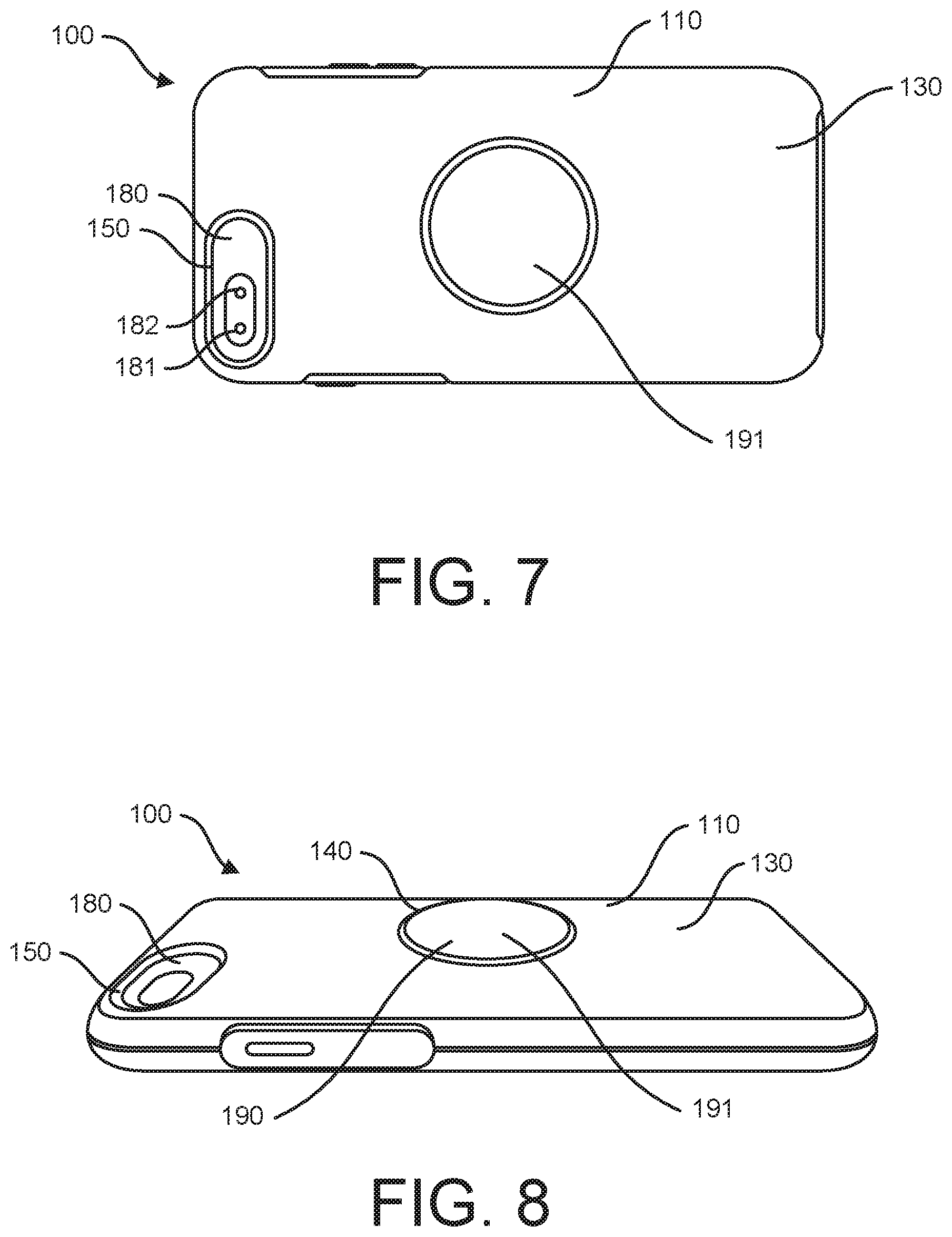
Protective case 100 also includes grip aperture 140 in the back surface of protective case 100. Grip aperture 140 extends from inside of protective case 100 through inner surface 120 and body 110 to provide an aperture or hole that extends all the way through to the back of the case. As discussed with respect to other figures herein, grip aperture 140 facilitates operation and use of a device grip, such as device grip 190, with a protective case, such as protective case 100. The size, shape, quantity, or position, of grip aperture 140 may vary. FIG. 3 illustrates a back view of protective case 100. Outer surface 130 of protective case 100 is visible in FIG. 3.
FIG. 4 illustrates a back perspective view of protective case 100 with device grip 190 installed. Although mostly hidden in FIG. 4, an electronic device 180 is installed in protective case 100 in FIG. 4 and can be partially seen through camera aperture 150. Electronic device 180 may be any type of phone, smartphone, tablet computer, gaming device, portable electronic device, audio player, video player, camera, portable computer, two-way radio, GPS receiver, and/or other portable device. Camera aperture 150 provides optical access for at least a camera lens 181 and/or a flash 182 of electronic device 180. Many other camera, flash, and lens configurations are possible.
As illustrated in FIG. 4, device grip 190 attaches directly to a back surface of electronic device 180 through grip aperture 140. Beneficially, protective case 100 does not interfere with the attachment of device grip 190 to electronic device 180. Device grip 190 can be attached to electronic device 180 in the same manner and position as it would be if protective case 100 was not present. In FIG. 4, device grip 190 is illustrated in an extended, partially extended, or use position.
FIG. 4 also illustrates an access port 170 for accessing an electrical interface of installed electronic device 180 (electrical interface not visible). The electrical interface may be for transmitting and/or receiving electrical data communication signals and/or power to/from electronic device 180. The electrical interface may include or may be configured to mate with a standardized electrical plug or connector such as, for example, a USB connector, a mini USB connector, a micro USB connector, an APPLE LIGHTNING.RTM. connector, a proprietary electronic connector, and/or an electrical connector of another type.
Protective case 100 may also permit access to other features of installed electronic device 180. For example, protective case 100 may permit access to an audio feature of electronic device 180, such as a speaker or headphone jack of electronic device 180. In some configurations, protective case 100 may include an aperture with a water impermeable membrane that allows sound to pass through the membrane while keeping water from passing through the associated aperture.
FIG. 5 illustrates a back perspective view of protective case 100 and device grip 190 in use by a user. Similar to FIG. 4, device grip 190 is in an extended position, or partially extended position, that enables the user to more reliably, more easily, and/or more steadily hold protective case 100 and installed electronic device 180. The user places one or two fingers around or under grip end 191 of device grip 190 in order to hold electronic device 180. Since expanding portion 192 of device grip 190 has a smaller diameter or smaller cross section than grip end 191, it is easier for the user to hold installed electronic device 180 and the chances of dropping it are reduced.
FIG. 6 illustrates a back perspective view of protective case 100 and device grip 190 in a viewing configuration on a surface 210. Surface 210 may be a desk, table, or tray on which a user wishes to position in order to view it without having to hold it. In some situations, expanding portion 192 of device grip 190 may pivot, flex, or snap in multiple directions to adjusting the resulting viewing angle of installed electronic device 180. Beneficially, protective case 100 permits this use and operation of device grip 190 and electronic device 180 to occur in a same or similar manner as it would if protective case 100 were not present.
FIG. 7 illustrates a back view of protective case 100 with electronic device 180 and device grip 190 in a non-extended position. This non-extended position may also be referred to as a stowed position, a storage position, a stored position, or a non-use position. FIG. 8 provides a side view of the configuration of FIG. 7. As illustrated in FIG. 8, back surface 130 of protective case 100 has a shape or contour that makes back surface 130 flush, substantially flush, or significantly flush with grip end 191 of device grip 190 when it is in the non-extended position. Because device grip 190 can be compressed to only a certain minimum height, without the improvements disclosed herein device grip 190 would extend past back surface 130 even in the stowed position. The resulting lip or edge of grip end 191 could make it difficult to slide the assembly in and out of pockets or bags and could result in unwanted snagging or catching. Further, a significant gap between an edge of grip end 191 and grip aperture 140 could be a path for dust, water, snow, mud, or debris to get inside protective case 100.
The contour or shape of back surface 130 extends up to meet the edge of grip end 191 at grip aperture 140 in order to provide a smoother back surface for the overall assembly even though protective case may have an overall or envelope thickness that is greater than it may otherwise have. The generally smoother overall envelope reduces or minimizes snagging or catching on pockets, bags, or other items when device grip 190 is in the non-extended position. This configuration may also provide a better overall aesthetic appearance. In this way, protective case 100 accommodates existing device grips, such as device grip 190, which may have a minimum thickness that is greater than a minimum back wall thickness of protective case 100. It should be noted that many shapes or contours of back surface 130 are possible as long as a smooth, somewhat smooth, flush, or somewhat flush interface is created between back surface 130 and grip end 191 at an edge of grip aperture 140.
In some examples, a thickness of the back wall of protective case 100 proximate grip aperture 140 is greater than thicknesses of other portions of the back wall such that outer surface 130 is approximately flush with grip end 191 when the device grip 190 is attached to the installed electronic device and is in a non-extended position. In some examples, outer surface 130 of the back wall of body 110 is non-planar such that outer surface 130 is approximately or substantially flush with grip end 191 when device grip 190 is attached to the installed electronic device and is in a non-extended position. In some examples, outer surface 130 of the back wall of body 110 of protective case 100 has a non-planar shape and is configured such that an outer edge of grip aperture 140 is proximate a distal end of the device grip 190 when device grip 190 is attached to the installed electronic device at a proximal end and is in a storage position.
In some examples, protective case 100 may be removable from electronic device 180 without removing device grip 190. This may be beneficial if an adhesive used to attach device grip 190 to electronic device 180 is permanent or semi-permanent.
It should be understood that many variations are possible to accommodate different types of device grips. Variations may include varying: a position of grip aperture 140, a shape of grip aperture 140, a size of grip aperture 140, a quantity of grip apertures, the thickness of the back wall of protective case 100, and/or one or more contours of back surface 130. The contour(s) may result in solid, hollow, or partially hollow portions of the back wall.
In some examples, a position of grip aperture 140 may be chosen based on known weight distribution characteristics of electronic device 180 and/or protective case 100 to achieve desired balance characteristics. In other examples, a position of grip aperture 140 may be chosen to improve or optimize use of an associated grip as a stand.
In some examples, back surface 130 may include colors or graphics which match or contrast with colors of graphics on grip end 191. In some cases, a non-round grip aperture may be used to better facilitate alignment or orientation of graphics.
Although protective case 100 is intended to work with already existing device grip designs, in some situations different lengths of device grips may be produced or offered to take into account or accommodate a thickness of protective case 100 such that the usable thickness of the extended device grip (see FIG. 5) is the same or similar as it would be in a standard installation in which no protective case was present.
In some examples, one or more contours of back may be chosen to better fit an inside of a user's hand or partially bent fingers in addition to accomplishing the other objectives disclosed herein. In other words, the back surface of protective case 100 may be curved to better fit a user's hand as well as provide a flush fit, or near flush fit, for a stowed device grip.
In some examples, each of grip aperture 140 and/or device grip 190 may include a gasket and/or gasket seat to form a dust-resistant, dustproof, water-resistant, waterproof, mud-resistant, mudproof, snow-resistant, and/or snowproof seal when device grip 190 is in the non-extended or stowed position. One or more of these features may be used in conjunction with an otherwise water-resistant or waterproof protective case 100.
In some examples, one or more areas of the edge of grip aperture 140 and/or grip end 191 may contain a small recess, cutout, gap, or notch which enables a user to get a fingernail or thin object between them to more easily extend it while providing minimal reduction of benefit to overall smooth, non-catching contour of the solution. The recess may be formed in grip aperture 140 and/or grip end 191. This recess may be in one particular area or in multiple distinct locations around the perimeter (for example, in two, three, or four locations). In other examples, a recess which facilitates extending of device grip 190 may exist around the entire perimeter of grip aperture 140 and/or grip end 191. In some examples, this feature may be implemented through use of a beveled or rounded edge in a specific area or the entire perimeter of grip aperture 140 and/or grip end 191.
In some examples, protective case 100 may include a removable plug to plug, close, or cover grip aperture 140 if not used and/or when not in use. In some examples, this plug may be formed as a part of body 110 such that it stays in place if a user does not use this option.
FIG. 9A illustrates a protective case 900 and a device grip cap 920. Protective case 900 is a protective case or cover for an electronic device, such as a smartphone or tablet computer, and may have any of the features, functions, and/or characteristics of protective case 100. However, protective case 900 may not necessarily include grip aperture 140 and/or may not have a thicker region, sloped region, or contoured region which provides a smooth interface up to a top edge of an installed device grip. In the example of FIG. 9A, device grip cap 920 provides an alternative solution that also provides a generally, most, substantially, or primarily smooth outer surface when device grip 190 is not in use in order to reduce the chances of it catching or snagging on edges of a pocket, bag, or other item.
FIG. 9B illustrates an end cross-sectional view of device grip cap 920 installed over a device grip 190 that is attached to protective case 900. In the example of FIG. 9B, device grip 190 is in the stowed or non-use position. Device grip 190 includes a tapered, accordion-like structure that allows it to be compressed or compacted when not in use. Device grip cap 920 fits over device grip 190 such that the back surface of the overall assembly is generally smooth, or at least smoother than it would be were device grip cap 920 not present. In this way, inadvertent snagging or catching of device grip 190 on another object is reduced when device grip 190 is in the stowed position. This configuration makes the overall assembly easier to slide in and out of pockets, bags, and/or similar storage areas.
Device grip cap 920 may be made of any material or combination of materials and may be attached to device grip 190 using any known method. In some examples, device grip cap 920 may have one or more transparent regions which allow a logo or graphics on a top of device grip 190 to remain visible even though device grip cap 920 is installed over it. Device grip cap 920 may have a shape, contours, and/or features that are different than those illustrated in FIGS. 9A-9D while still using the same techniques and/or achieving similar results.
When device grip 190 is in the unstowed or use position, device grip cap 920 is moved away from protective case 900 along with the top of device grip 190 to still allow device grip 190 to be used as intended and provide the benefits described herein. Beneficially, device grip cap 920 provides a smoother back surface for the assembly without necessarily having to utilize a contoured back surface on the protective case as illustrated in FIGS. 3-8. In other words, the benefit can be achieved without a specialized protective case having the features described in FIGS. 3-8. FIG. 9C illustrates an end view of protective case 900 and device grip cap 920 installed over device grip 190.
FIG. 9D illustrates device grip cap 920 including an opening feature 925. Opening feature 925 may be any feature which makes it easier to get a finger-hold or grip on device grip cap 920 to pull it and device grip 190 to the unstowed position. Opening feature 925 may include a cutout, slot, hole, recess, ridge, protrusion, lip, and/or textured surface for getting a better grip on device grip cap 920 for deployment. Multiple instances of opening feature 925 may be distributed around the perimeter of device grip cap 920. Opening feature 925 may also be configured for use with a small tool in addition to, or in place of, operation using a finger.
FIG. 10A illustrates protective case 900 and a bistable cap 1020. Bistable cap 1020 provides an alternative solution for providing a generally smooth outer surface when device grip 190 is not in use in order to reduce the chances of it snagging on edges of a pocket, bag, or other item. FIG. 10B illustrates an end cross-sectional view of bistable cap 1020 installed over a device grip 190 that is attached to protective case 900. In the example of FIG. 10B, device grip 190 is in the stowed or non-use position. It includes a tapered, accordion-like structure that allows it to be compressed when not in use. Bistable cap 1020 fits over device grip 190 such that the back surface of the overall assembly is generally smooth, or at least smoother than it would be if bistable cap 1020 not present. In this way, inadvertent snagging or catching of device grip 190 is reduced when device grip 190 is in the stowed position.
Bistable cap 1020 may be made of any material or combination of materials and may be attached to device grip 190 using any known method. Bistable cap 1020 generally has two stable states or positions, which are illustrated in FIGS. 10A-10C. In one example, bistable cap 1020 has a shape similar to a portion of a sphere or dome with a concave side and convex side and can be reversibly reconfigured such that the concave and convex sides are alternated. In other words, it may be a portion of a dome or sphere that can be turned `inside out.` In some examples, bistable cap 1020 may not necessarily be spherical. Bistable cap 1020 may have a shape, contours, and/or features that are different than those illustrated in FIGS. 10A-10C.
When a user wishes to use device grip 190, a center portion of bistable cap 1020 is pressed with a finger or other object in a generally downward direction. This externally applied force or pressure causes bistable cap to 1020 transition to the other of its two stable states, as illustrated in FIG. 10C. It temporarily remains in this state to allow a user to access and/or use device grip 190. When the user is finished, one or more edges of bistable cap 1020 are pressed to cause it to return to the initial state illustrated in FIG. 10A.
Device grip cap 920 and/or bistable cap 1020 may also be removable or replaceable and may include graphics, colors, pictures, and/or patterns that are selected to complement or coordinate with protective case 100.
While the examples of FIGS. 9A-9D and 10A-10C are illustrated with respect to a protective case 900, any of the elements or features may be implemented or used with a protective case. In other words, any of device grip 190, device grip cap 920, and/or bistable cap 1020 may be used directly with an electronic device even though no protective case is present. In these examples, device grip 190 may be attached directly to a back surface of the electronic device. In some cases, the term `housing` may be used herein to refer to either the primary housing of an electronic device and/or a supplemental protective case or cover for an electronic device.
FIG. 11 illustrates a back view of a protective case 1100 with device grip 190 in a stowed position. Protective case 1100 may contain any of the features, functions, elements, and/or characteristics of previously described protective case 100 and/or protective case 900. In the illustration of FIG. 11, an electronic device is removably insertable into protective case 1100 from an opposite side of protective case 1100 (from the side facing into the page in FIG. 11). Sides 1112 of protective case 1100 hold the electronic device in protective case 1100 and may be flexible or pliable. Other protective case configurations are possible.
Back surface 1110 of protective case 1100 has a shape which includes contours selected to better accommodate grip 190. Specifically, back surface 1110 includes a concave area 1118 in which device grip 190 is attached to protective case 1100. Concave area 1118 may also be described as a recess, a recessed area, and/or a cavity. When device grip 190 is in a stowed or collapsed position, a significant portion, a majority of, or all of device grip 190 is positioned within concave area 1118. As with other examples discussed herein, this configuration provides a smoother overall surface or envelope of protective case 1100, including device grip 190. This design reduces the chances that device grip 190 will get snagged on an edge of a pocket or a bag when device grip 190 is not in use and is in the stowed position. In some examples, stowed device grip 190 may be completely flush with back surface 1110. In other examples, stowed device grip 190 may be partially or substantially flush with back surface 1110.
Back surface 1110 of protective case 1100 may include a shape or contours that slope upward from the sides 1112 of protective case 1100 to the edge of concave area 1118. An inner surface of protective case 1100 may include a similar corresponding shape or contour. The sloped back surface and contours provide the space necessary between back surface 1110 and a back surface of an installed electronic device to recess concave area 1118 between them. In some examples, a top edge of stowed device grip 190 may be fully within concave area 1118 and may be below a plane of the upper rim or edge of concave area 1118. In other words, when back surface 1110 of protective case 1100 is laid on a flat surface, stowed device grip 190 may be sufficiently recessed to not contact the flat surface. However, in other configurations, stowed device grip 190 may be flush with back surface 1110 or may extend slightly above the edges of concave area 1118 even when in the stowed position.
In addition, there may be a gap, opening, or slot between a top edge of stowed device grip 190 and the rim or edge of recessed area 1118. This gap or opening makes it easier to for a user to grasp an edge of stowed device grip 190 to pull it out to the extended position. This gap, opening, or slot may extend all the way around device grip 190 or may be limited to a portion of recessed area 1118 and/or device grip 190.
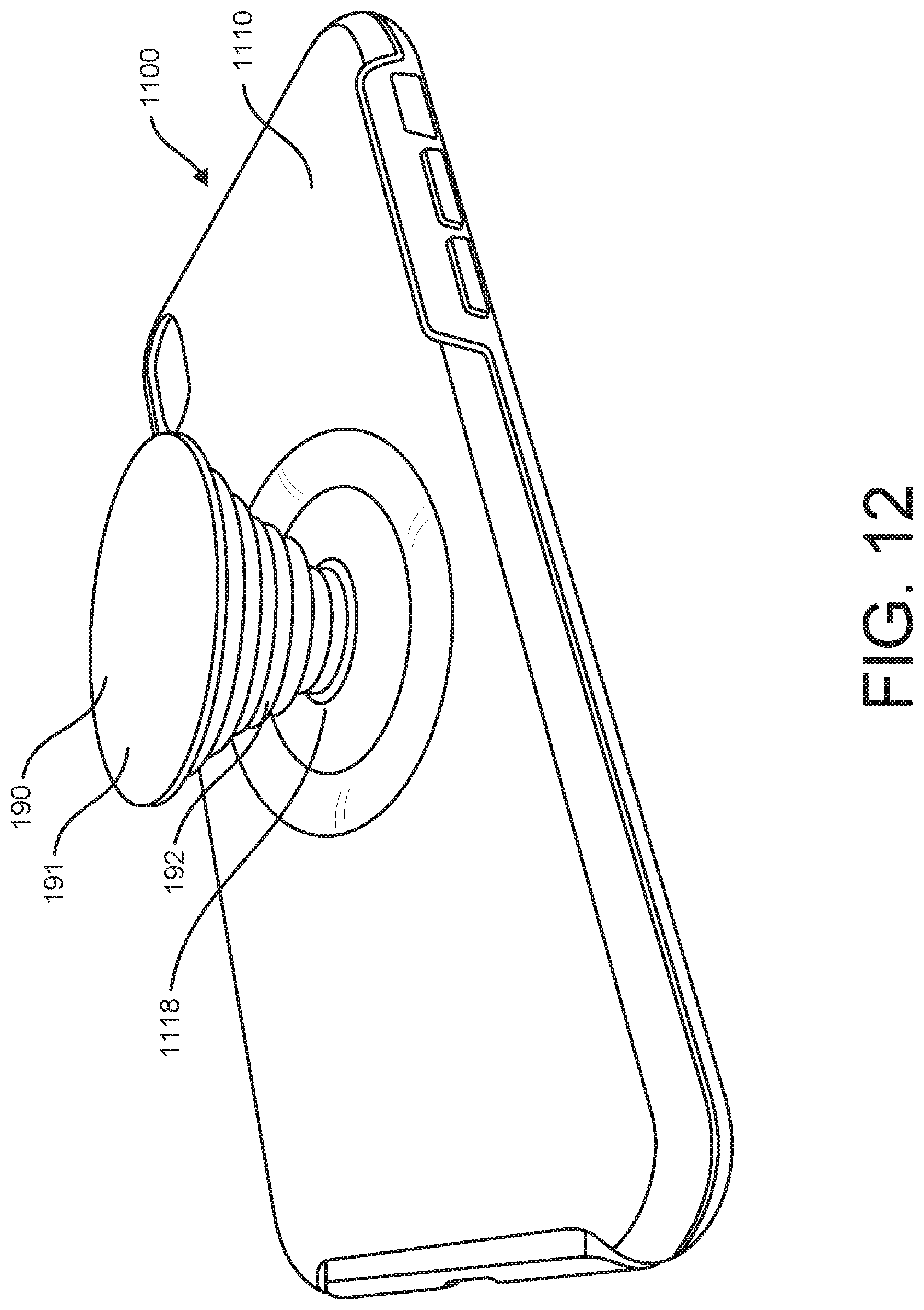
FIG. 12 illustrates protective case 1100 with device grip 190 is an extended or use position. This configuration may provide many advantages as discussed in the examples of FIGS. 4-6 and elsewhere herein. In this configuration, device grip 190 extends significantly beyond concave area 1118 so it can be used for holding or supporting protective case 1100 in various ways. Expanding portion 192 of device grip 190 is also visible in FIG. 12. While device grip 190 and concave area 1118 are round in these examples, other compatible shapes are possible including oval, square, rectangular, triangular, or any polygon.
FIG. 13 illustrates a front perspective view of protective case 1100 which illustrates inside surface 1111 of protective case 1100. An opposing or back side of concave area 1118 is also visible on inside surface 1111. However, this internal structure or shape is not necessary and inside surface may be flat or planar. In the latter case, the back wall of protective case 100 may vary in thickness to provide the desired contour and/or a cavity may exist between inside surface 1111 and outside surface 1110.
FIG. 14 illustrates protective case 1100 with device grip 190 detached. Device grip 190 is illustrated with expanding portion 192 in a collapsed position. In FIG. 14, a receiver 193 is visible on back surface 1110 in concave area 1118. Receiver 193 may be any type of mechanical structure or feature configured to removably engage with and/or removably attach to an attachment feature 194 of device grip 190. Receiver 193 and attachment feature 194 may include any features or elements which allow them to temporarily engage, connect, attach, or interface, but also be selectively disengaged, disconnected, and/or detached. Receiver 193 may be molded as part of protective case 1100 or may be a separate element that is adhered to or affixed to protective case 1100. In other examples, receiver 193 may be a separate component that becomes affixed to protective case 1100 as part of a molding process of protective case 1100. Other configurations are possible.
The configuration in FIG. 14 provides several distinct advantages. First, device grip 190 may be used with an electronic device without have to adhere it directly to the electronic device. Second, device grip 190 may be collapsed or stowed partially or completely into concave area 1118 when not in use thereby reducing unwanted catching or snagging on other objects. Third, device grip 190 is readily removable from the protective case. It may be desirable to remove the device grip for a number of reasons including: because it is not expected to be used in the near future, in order to switch to a different device grip having different colors, graphics, or features, and/or to replace a broken device grip.
Attachment feature 194 of device grip 190 may attached to receiver 193 in a variety of ways. In one example, the two elements may utilize rotary engage features that attach or detach by rotating the two elements with respect to each other. One or both components may also include retention features which cause them engage in a manner in which they click or snap into place and require additional force for removal. Device grip 190 may be configured such that the top 191 only engages attachment feature 194 to rotatably remove when device grip 190 is in the collapsed position and/or when a downward force is applied. In this way, device grip 190 may only be removable when it is in the collapsed position and may reduce the chances of unintended detachment.
FIG. 15 illustrates a back view of a protective case 1500 with device grip 190 in a stowed position. Protective case 1500 may contain any of the features, functions, elements, and/or characteristics of previously described protective case 100, protective case 900, and/or protective case 1100. In the illustration of FIG. 15, an electronic device is removably insertable into protective case 1500 from an opposite side of protective case 1500 (from the side facing into the page in FIG. 15).
FIG. 16 illustrates protective case 1500 with device grip 190 in an extended or use position. This configuration may provide advantages similar to those discussed with respect to the examples of FIGS. 4-6 and elsewhere herein. In this configuration, device grip 190 extends so it can be used for holding or supporting protective case 1500 in various ways. Expanding portion 192 of grip 190 is also visible in FIG. 16. FIG. 16 illustrates that back surface 1510 of protective case 1500 includes a cutout or recess 1518 that corresponds a size and shape of device grip 190. Recess 1518 allows at least a portion of device grip 190 to be recessed with respect to back surface 1510 such that device grip 190 protrudes less than it otherwise would when it is in the stowed position.
FIG. 17 illustrates protective case 1500 with device grip 190 detached. Device grip 190 is illustrated with expanding portion 192 in a collapsed position. In FIG. 17, a receiver 193 is visible on back surface 1510 in recessed area 1518. Receiver 193 may be molded as part of protective case 1500 or may be a separate element that is adhered to or affixed to protective case 1500. In other examples, receiver 193 may be a separate component that becomes affixed to protective case 1500 as part of the molding process of protective case 1500.
The configuration illustrated in FIG. 17 provides several distinct advantages. First, device grip 190 may be used with an electronic device without have to adhere it directly to the electronic device. Second, device grip 190 may be collapsed or stowed partially into recessed area 1518 when not in use to reduce unwanted catching of it on other objects, such as the edge of a person's pocket. Third, device grip 190 is readily removable from the protective case. It may be desirable to remove the device grip for a number of reasons including: because it is not expected to be used in the near future, in order to switch to a different device grip, and/or to replace a broken device grip. In some examples, a user may wish to switch between device grips having different colors or graphics.
FIG. 18 illustrates the configuration of FIG. 17 with protective case 1500 further disassembled. Protective case 1500 includes an inner shell 1501 and an outer layer 1502 that fits over inner shell 1501. In some examples, outer layer 1502 may be a pliable cushion layer. Inner shell 1501 includes receiver 193 and recessed area 1518. Outer layer 1502 includes an opening or aperture 1507 that coincides with recessed area 1518 and device grip 190 when attached. This configuration allows device grip 190 to be at least partially recessed into protective case 1500 in in order to reduce the amount it protrudes when in the stowed position while still leaving enough of it accessible so a user can grasp it with a fingertip or fingernail.
Various components described herein may be manufactured, provided, or sold in the form of a system or a kit. The system or kit may include any combination of: a protective case or cover having any combination of the features described herein and a compatible device grip. The system or kit need not include every component or feature described herein.
The elements, components, and steps described herein are meant to exemplify some types of possibilities. In no way should the aforementioned examples limit the scope of the invention, as they are only exemplary embodiments.
The phrases "in some embodiments," "according to some embodiments," "in the embodiments shown," "in other embodiments," "in some examples," "in other examples," "in some cases," "in some situations," "in one configuration," "in another configuration," and the like generally mean that the particular technique, feature, structure, or characteristic following the phrase is included in at least one embodiment of the present invention and/or may be included in more than one embodiment of the present invention. In addition, such phrases do not necessarily refer to the same embodiments or to different embodiments.
The foregoing disclosure has been presented for purposes of illustration and description. Other modifications and variations may be possible in view of the above teachings. The embodiments described in the foregoing disclosure were chosen to explain the principles of the concept and its practical application to enable others skilled in the art to best utilize the invention. It is intended that the claims be construed to include other alternative embodiments of the invention except as limited by the prior art.
* * * * *
References
D00000
D00001
D00002
D00003
D00004
D00005
D00006
D00007
D00008
D00009
D00010
D00011
D00012
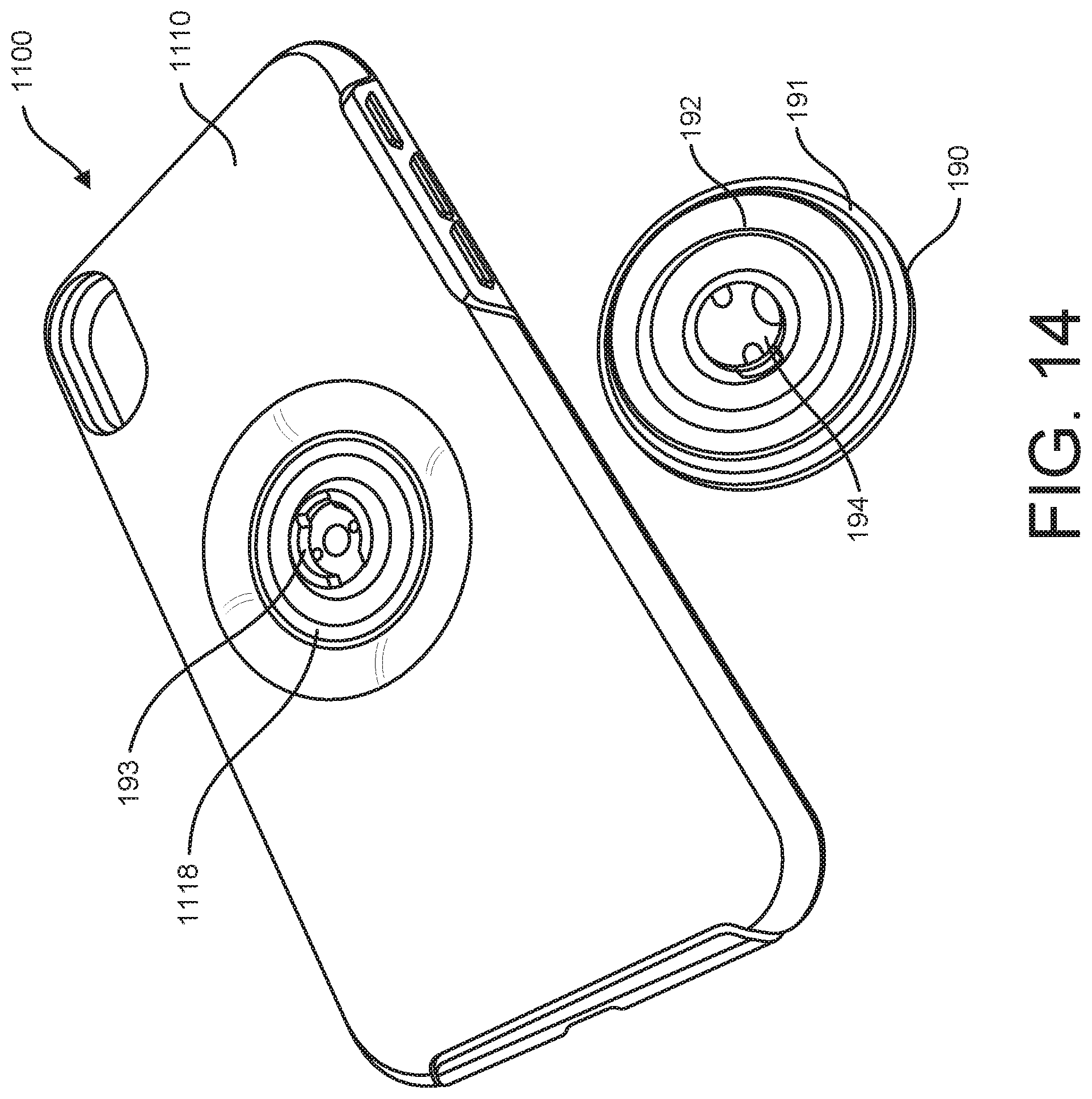
D00013

D00014

D00015
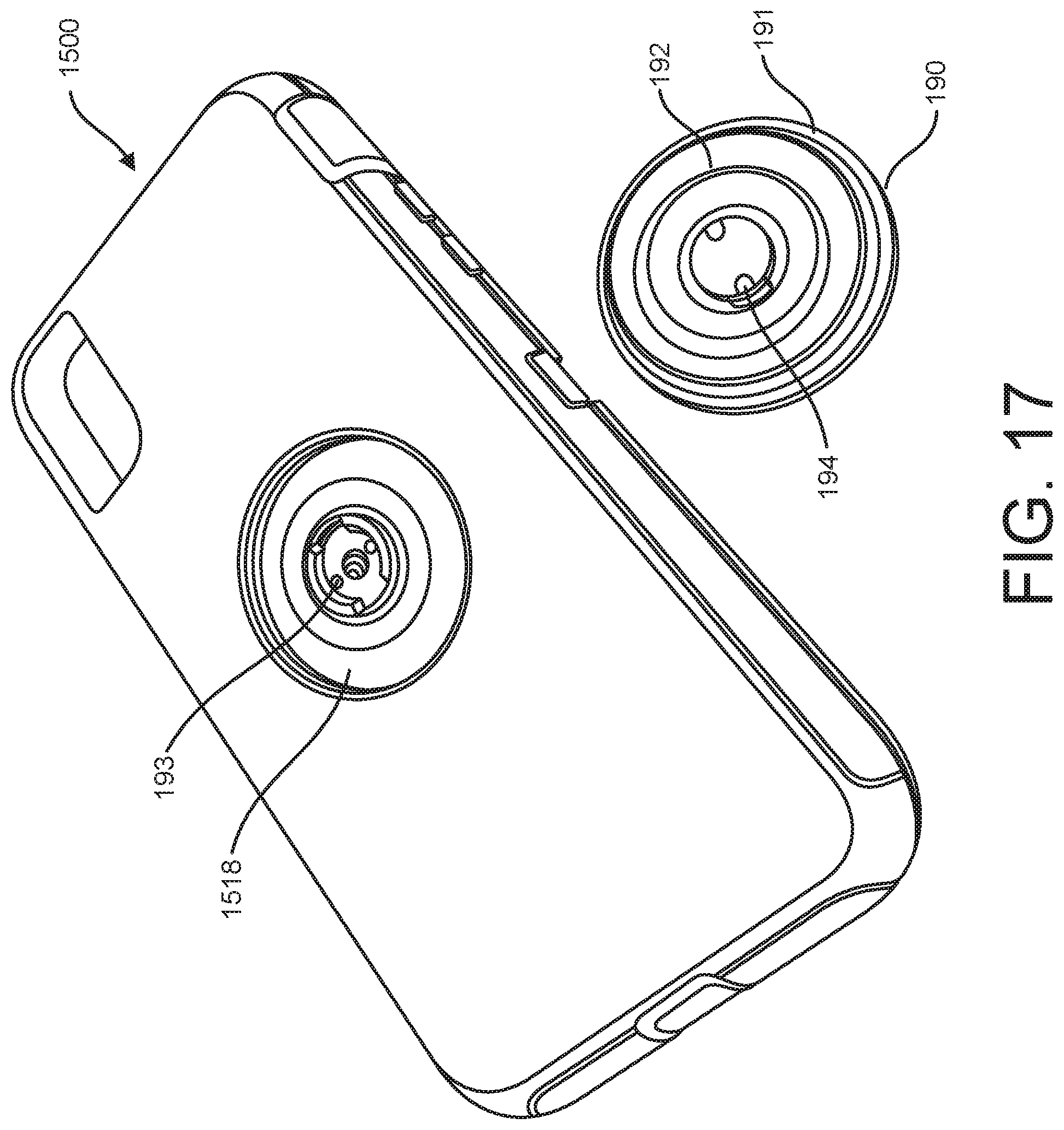
D00016
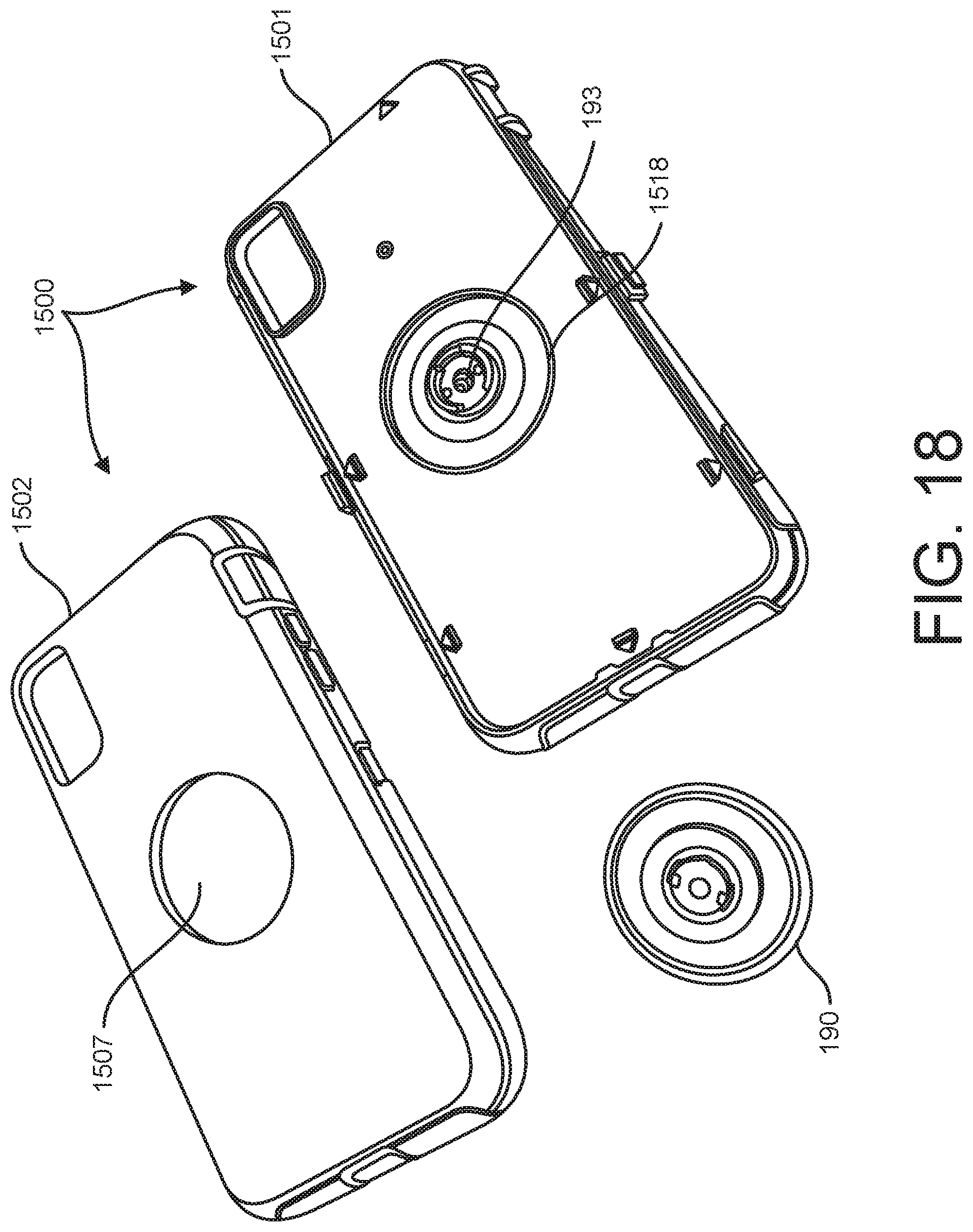
XML
uspto.report is an independent third-party trademark research tool that is not affiliated, endorsed, or sponsored by the United States Patent and Trademark Office (USPTO) or any other governmental organization. The information provided by uspto.report is based on publicly available data at the time of writing and is intended for informational purposes only.
While we strive to provide accurate and up-to-date information, we do not guarantee the accuracy, completeness, reliability, or suitability of the information displayed on this site. The use of this site is at your own risk. Any reliance you place on such information is therefore strictly at your own risk.
All official trademark data, including owner information, should be verified by visiting the official USPTO website at www.uspto.gov. This site is not intended to replace professional legal advice and should not be used as a substitute for consulting with a legal professional who is knowledgeable about trademark law.