Wheeled trailer sandwich structure including grooved outer sheet
Ebnother , et al.
U.S. patent number 10,710,328 [Application Number 16/158,435] was granted by the patent office on 2020-07-14 for wheeled trailer sandwich structure including grooved outer sheet. This patent grant is currently assigned to CellTech Metals, Inc.. The grantee listed for this patent is CELLTECH METALS, INC.. Invention is credited to Douglas Cox, Fabien Ebnother.


| United States Patent | 10,710,328 |
| Ebnother , et al. | July 14, 2020 |
Wheeled trailer sandwich structure including grooved outer sheet
Abstract
A sandwich structure employs a core sheet including alternating peaks and valleys therein, and at least one outer face sheet including grooves or ribs therein. In another aspect, a sandwich structure includes at least one core and at least one adhesively bonded outer face sheet including elongated grooves or ribs formed therein. Yet another aspect of a sandwich structure has raised ridges bridging between adjacent peaks in a core sheet in one direction but not in a perpendicular direction, which synergistically interface, engage or contact with grooves or ribs formed in an outer face sheet.
| Inventors: | Ebnother; Fabien (Munich, DE), Cox; Douglas (Oceanside, CA) | ||||||||||
|---|---|---|---|---|---|---|---|---|---|---|---|
| Applicant: |
|
||||||||||
| Assignee: | CellTech Metals, Inc. (Searcy,
AR) |
||||||||||
| Family ID: | 65232057 | ||||||||||
| Appl. No.: | 16/158,435 | ||||||||||
| Filed: | October 12, 2018 |
Prior Publication Data
| Document Identifier | Publication Date | |
|---|---|---|
| US 20190039344 A1 | Feb 7, 2019 | |
Related U.S. Patent Documents
| Application Number | Filing Date | Patent Number | Issue Date | ||
|---|---|---|---|---|---|
| 15303958 | 10124555 | ||||
| PCT/US2015/026839 | Apr 21, 2015 | ||||
| 61982453 | Apr 22, 2014 | ||||
| Current U.S. Class: | 1/1 |
| Current CPC Class: | B32B 3/30 (20130101); B32B 5/18 (20130101); B32B 7/08 (20130101); B32B 7/05 (20190101); B32B 25/18 (20130101); B32B 7/09 (20190101); B65D 88/02 (20130101); B32B 7/03 (20190101); B32B 7/12 (20130101); B32B 15/011 (20130101); B32B 15/016 (20130101); B32B 15/20 (20130101); B32B 15/01 (20130101); B32B 7/14 (20130101); B32B 15/18 (20130101); B32B 3/28 (20130101); B32B 15/043 (20130101); B32B 15/04 (20130101); B32B 15/046 (20130101); B32B 2419/04 (20130101); B32B 2307/542 (20130101); B32B 2439/00 (20130101); Y10T 428/1241 (20150115); B32B 2605/08 (20130101); B32B 2250/03 (20130101); B32B 2255/06 (20130101); Y10T 428/24669 (20150115); B32B 2419/00 (20130101); Y10T 428/1234 (20150115); B32B 2605/00 (20130101); Y10T 428/12417 (20150115); B32B 2307/724 (20130101); B32B 2255/26 (20130101); B32B 2250/40 (20130101); B32B 2607/00 (20130101); B32B 2439/62 (20130101) |
| Current International Class: | B32B 3/28 (20060101); B32B 7/14 (20060101); B32B 15/18 (20060101); B32B 15/20 (20060101); B32B 15/01 (20060101); B32B 7/12 (20060101); B65D 88/02 (20060101); B32B 3/30 (20060101); B32B 15/04 (20060101); B32B 7/08 (20190101); B32B 7/03 (20190101); B32B 7/05 (20190101) |
References Cited [Referenced By]
U.S. Patent Documents
| 782558 | February 1905 | Hahn |
| 2087010 | July 1937 | Wardle |
| 2391997 | January 1946 | Noble |
| 2441476 | May 1948 | Ewald |
| 2481046 | September 1949 | Scurlock |
| 2605064 | July 1952 | Davis |
| 2738297 | March 1956 | Pfisterhammer |
| 2809908 | October 1957 | French |
| 2950788 | August 1960 | Edgar |
| 3013641 | December 1961 | Compton |
| 3071853 | January 1963 | Price et al. |
| 3086899 | April 1963 | Smith |
| 3151712 | October 1964 | Jackson |
| 3173383 | March 1965 | Eggert |
| 3217845 | November 1965 | Reynolds |
| 3227598 | January 1966 | Robb |
| 3432859 | March 1969 | Jordan |
| 3481642 | December 1969 | Campbell |
| 3525663 | August 1970 | Hale |
| 3597891 | August 1971 | Martin |
| 3742663 | July 1973 | Duskin |
| 3757559 | September 1973 | Welsh |
| 3834487 | September 1974 | Hale |
| 3865679 | February 1975 | Hale |
| 3876492 | April 1975 | Schott |
| 3914486 | October 1975 | Borgford |
| 3938963 | February 1976 | Hale |
| 3950259 | April 1976 | Pallo et al. |
| 4025996 | May 1977 | Saveker |
| 4044186 | August 1977 | Stangeland |
| 4049855 | September 1977 | Cogan |
| 4077247 | March 1978 | Stewart |
| 4275663 | June 1981 | Sivachenko et al. |
| 4344995 | August 1982 | Hammer |
| 4356678 | November 1982 | Andrews et al. |
| 4411121 | October 1983 | Blacklin et al. |
| 4635992 | January 1987 | Hamilton et al. |
| 4718214 | January 1988 | Waggoner |
| 4910065 | March 1990 | McKinney |
| 5030488 | July 1991 | Sobolev |
| 5195580 | March 1993 | Hoeffken |
| 5366787 | November 1994 | Yasui et al. |
| 5580637 | December 1996 | Konta et al. |
| 5678715 | October 1997 | Sjostedt et al. |
| 5791118 | August 1998 | Jordan |
| 5860693 | January 1999 | Ehrlich |
| 5887402 | March 1999 | Ruggie et al. |
| 6183879 | February 2001 | Deeley |
| 6220651 | April 2001 | Ehrlich |
| 6257043 | July 2001 | Wiens |
| 6412854 | July 2002 | Ehrlich |
| 6547280 | April 2003 | Ashmead |
| 6846559 | January 2005 | Czaplicki et al. |
| 6908143 | June 2005 | Ashmead |
| 6928848 | August 2005 | Golovashchenko et al. |
| 6939599 | September 2005 | Clark |
| 6959959 | November 2005 | Roush |
| 7010897 | March 2006 | Kuppers |
| 7025408 | April 2006 | Jones et al. |
| 7100971 | September 2006 | Pines |
| 7214018 | May 2007 | Lussier |
| 7267393 | September 2007 | Booher |
| 7401844 | July 2008 | Lemmons |
| 7527325 | May 2009 | Yurgevich |
| 7621589 | November 2009 | Gerome |
| 7648058 | January 2010 | Straza |
| 7752729 | July 2010 | Faehrrolfes et al. |
| 7753254 | July 2010 | Straza |
| 7757931 | July 2010 | Straza |
| 7798447 | September 2010 | Frantz et al. |
| 7927708 | April 2011 | Mizrahi |
| 7931328 | April 2011 | Lewallen et al. |
| 8016152 | September 2011 | Roush et al. |
| 8205642 | June 2012 | Straza |
| 8419110 | April 2013 | Katz et al. |
| 8426010 | April 2013 | Stadthagen-Gonzalez |
| 8434472 | May 2013 | Hanson et al. |
| 8506221 | August 2013 | Pattison et al. |
| 8540099 | September 2013 | Roush |
| 8580061 | November 2013 | Cik |
| 8835016 | September 2014 | Ebnoether |
| 9067729 | June 2015 | Fenton |
| 9764780 | September 2017 | Zehner et al. |
| 9884660 | February 2018 | Fenton |
| 9884661 | February 2018 | Fenton |
| 9925736 | March 2018 | Cox et al. |
| 10112248 | October 2018 | Gould et al. |
| 10124555 | November 2018 | Ebnother et al. |
| 10144582 | December 2018 | Ebnother et al. |
| 2003/0080586 | May 2003 | Ehrlich |
| 2003/0210966 | November 2003 | Haire |
| 2005/0029708 | February 2005 | Coyle |
| 2005/0084703 | April 2005 | Ashmead |
| 2005/0230033 | October 2005 | Faehrrolfes et al. |
| 2007/0114269 | May 2007 | Straza |
| 2008/0292898 | November 2008 | Straza |
| 2009/0053548 | February 2009 | Straza |
| 2009/0159592 | June 2009 | Vitalis et al. |
| 2012/0234470 | September 2012 | Nishio et al. |
| 2012/0305217 | December 2012 | Cowburn et al. |
| 2013/0224419 | August 2013 | Lee et al. |
| 2013/0244006 | September 2013 | Ebnoether |
| 2013/0330521 | December 2013 | Ebnoether |
| 2015/0044494 | February 2015 | Ebnoether |
| 2015/0078804 | March 2015 | Ehrlich |
| 2015/0165724 | June 2015 | Cox et al. |
| 2017/0036415 | February 2017 | Ebnother et al. |
| 2017/0274465 | September 2017 | Gould et al. |
| 2017/0327310 | November 2017 | Ebnother et al. |
| 2018/0170449 | June 2018 | Cox et al. |
| 2018/0207902 | July 2018 | Cox et al. |
| 2182703 | May 1987 | GB | |||
| WO-2015/148707 | Oct 2015 | WO | |||
Other References
|
Kim, Jang-Kyo, et al.; "Forming and failure behaviour of coated, laminated and sandwiched sheet metals: a review", Journal of Materials Processing Technology, 63, 1997, pp. 33-42. cited by applicant . Van Straalen, Ijsbrand J.; "Comprehensive Overview of Theories for Sandwich Panels", TNO Building and Construction Research, 1998, pp. 48-70. cited by applicant . Stoffer, Harry; "Some suppliers see dollars in a higher CAFE", Automotive News, Crain Communications, Inc., Jul. 2, 2007, two pages. cited by applicant . Carey, John; "What's Next--Green Biz Materials of New Plastics and a Steel Sandwich", BusinessWeek, Oct. 22, 2007, one page. cited by applicant . " . . . Honeycomb Structure Holds Potential", Autotech Daily, Apr. 15, 2008, one page. cited by applicant . Vasilash, Gary S.; "From Small Things: Big Differences", Automotive Design and Production, Jun. 2008, one page. cited by applicant . "UltraSteel" brochure published by Hadley Group in Oct. 2010, 8 pages. cited by applicant . Ebnoether, Fabien, et al.; "Predicting ductile fracture of low carbon steel sheets: Stress-based versus mixed stress/strain-based Mohr-Coulomb model;" International Journal of Solids and Structures 50 (2013; published online Dec. 27, 2012); pp. 1055-1066. cited by applicant . Photos of Hyundai "EcoCell" trailer, containing doors including CellTech LLC's three sheet steel sandwich, shown at U.S. tradeshow in Mar. 2013. cited by applicant . "Whiting AirCell Availabity," Whiting airCell promotion, Sep. 26, 2013, three pages. cited by applicant . "airCELL--Innovative Panels for the Truck & Trailer Industries", Whiting, published before Dec. 4, 2013, one page. cited by applicant . "Meyer--Laminating machines for technical textiles, foams, nonwoven, foils, fabrics," http.//www.meyer-machines.com/engl/Products/Laminating/laminating.html, printed from internet, believed to have been published prior to Dec. 13, 2013, one page. cited by applicant . "airCELL the revolutionary all-steel sandwich panel that increases strength and reduces weight for trailer side walls and doors" Whiting, published prior to Nov. 2013, four pages. cited by applicant. |
Primary Examiner: Krupicka; Adam
Attorney, Agent or Firm: Harness, Dickey & Pierce, PLC
Parent Case Text
CROSS-REFERENCE TO RELATED APPLICATIONS
This application is a continuation of U.S. patent application Ser. No. 15/303,958, filed on Oct. 13, 2016, which is a National Stage entry of PCT/US2015/026839, filed Apr. 21, 2015, which claims the benefit of U.S. Provisional Patent Application No. 61/982,453, filed Apr. 22, 2014, all of which are incorporated by reference herein.
Claims
The invention claimed is:
1. A wheeled trailer sandwich structure comprising: outer metallic face sheets; a metallic core sheet including alternating peaks and valleys therein, the core sheet adhesively affixed between the outer face sheets to create a wheeled trailer wall or floor sandwich; and at least one of the outer face sheets comprising multiple parallel elongated grooves which each include a substantially flat bottom wall, a lateral width of which is greater than three times a depth of the bottom wall from a nominal surface of the associated outer face sheet.
2. The sandwich structure of claim 1, wherein the core sheet includes raised ridges bridging between adjacent of the peaks at one direction but not in the perpendicular direction, and the groove extends between peaks of the core sheet.
3. The sandwich structure of claim 1, wherein air gaps are present between the grooves and the peaks of the core sheet.
4. The sandwich structure of claim 1, wherein each of the grooves includes angular side walls between the nominal surface and the bottom wall, and the face sheets are flat between the grooves.
5. The sandwich structure of claim 1, further comprising at least one of: (a) an adhesive or (b) foam, is located against the groove.
6. The sandwich structure of claim 1, wherein each of the grooves have a substantially U-shaped cross-section.
7. The sandwich structure of claim 1, wherein a depth of each of the grooves is greater than a thickness of the associated face sheet, and the lateral width of the bottom wall is greater than five times the depth.
8. The sandwich structure of claim 1, wherein a depth of each of the grooves is between one and five times a thickness of an associated one of the outer face sheets, and a metal grain structure of at least one of the sheets is different in a feeding direction than in a cross-feeding direction.
9. The sandwich structure of claim 1, wherein a distance S between adjacent pairs of the grooves along a width direction W, is N times a node spacing of a peak pattern of the core sheet: S.sub.GROOVE=N*S.sub.NODE.
10. The sandwich structure of claim 1, wherein there are at least three of the grooves parallel to each other in each of the outer sheets, and the peaks and valleys are embossed in the core sheet.
11. The sandwich structure of claim 1, wherein there are air gaps between the grooves and the core sheet, and an out-of-plane shear strength of the core sheet is at least 1.05 times greater in a first direction as compared to a perpendicular second direction.
12. The sandwich structure of claim 1, wherein the nominal surfaces of the face sheets are flat and parallel, and wherein the peaks include substantially circular lands.
13. The sandwich structure of claim 1, wherein the sandwich structure is a wall of a wheeled trailer pulled by a truck.
14. A wheeled trailer sandwich structure comprising: outer face sheets; a core sheet including alternating peaks and valleys therein, the core sheet affixed between the outer face sheets to create a wheeled trailer wall or floor sandwich; at least one of the outer face sheets including at least one elongated groove, with an air gap being located between the groove and the core sheet; and adhesive bonding the face sheets to the core sheet.
15. The sandwich structure of claim 14, wherein the at least one groove has a substantially U-shaped cross-section with a substantially flat bottom.
16. The sandwich structure of claim 15, wherein the bottom has a lateral width greater than three times its depth.
17. The sandwich structure of claim 14, wherein the at least one groove has a substantially V-shaped cross-section.
18. The sandwich structure of claim 14, wherein a depth of the groove is greater than a thickness of the associated one of the outer face sheets.
19. The sandwich structure of claim 14, wherein a distance S between adjacent pairs of the grooves along a width direction W, is N times a node spacing of a peak pattern of the core sheet: S.sub.GROOVE=N*S.sub.NODE.
20. The sandwich structure of claim 14, wherein there are at least three of the grooves parallel to each other in the sandwich, and the peaks and valleys are embossed in the core sheet.
21. The sandwich structure of claim 14, wherein the sheets are metallic, and a metal grain structure of at least one of the sheets is different in one direction version a perpendicular second direction.
22. A wheeled trailer sandwich structure comprising: outer metallic face sheets; a metallic core sheet including alternating peaks and valleys therein, the core sheet affixed between the outer face sheets to create the wheeled trailer sandwich structure; and a first of the outer face sheets including at least one elongated groove which inwardly projects toward a second of the outer face sheets, the groove including tapered sides spanned by a substantially flat bottom, the bottom having a lateral width at least three times greater than a depth.
23. The sandwich structure of claim 22, wherein the core sheet includes raised ridges bridging between adjacent of the peaks at one direction but not in the perpendicular direction, the ridges being thinner than the peaks, the peaks having a substantially circular top, and the peaks and valleys are embossed in the core sheet.
24. The sandwich structure of claim 22, wherein air gaps are present between the groove and the core sheet.
25. The sandwich structure of claim 24, wherein the sandwich structure is a wall of a wheeled trailer pulled by a truck.
26. The sandwich structure of claim 22, wherein there are at least three of the grooves parallel to each other in the associated outer sheet which is flat between the grooves.
27. The sandwich structure of claim 26, wherein the sandwich structure is a wall of a wheeled trailer pulled by a truck.
28. The sandwich structure of claim 22, wherein there are air gaps between the grooves and the core sheet, and an out-of-plane shear strength of the core sheet is at least 1.05 times greater in a first direction as compared to a perpendicular second direction.
29. The sandwich structure of claim 22, wherein: the peaks of the core sheet are substantially circular in a true view; and a metal grain structure of the core sheet is different in one direction versus a perpendicular direction.
30. The sandwich structure of claim 22, further comprising adhesive affixing the outer face sheets to the core sheet.
Description
BACKGROUND
The present invention relates generally to sandwich structures and more particularly to a sandwich structure including a core having alternating peaks and valleys, and one or more outer sheets including grooves.
Metallic sandwich structures having outer and core layers are known in the industry. For example, reference is made to the following U.S. Pat. No. 7,752,729 entitled "Method for Shaping a Metallic Flat Material, Method for the Manufacture of a Composite Material and Devices for Performing these Methods" which issued to Faehrrolfes et al. on Jul. 13, 2010; U.S. Pat. No. 7,648,058 entitled "Formed Metal Core Sandwich Structure and Method and System for Making Same" which issued to Straza on Jan. 19, 2010, and is commonly owned herewith; and U.S. Pat. No. 3,525,663 entitled "Anticlastic Cellular Core Structure having Biaxial Rectilinear Truss Patterns" which issued to Hale on Aug. 25, 1970; all of which are incorporated by reference herein. The Hale patent, however, teaches the use of vertically operable stamping dies to form nodes in a heated core sheet, with the objective of obtaining the same flexual and shear strength in all planes. A core stamped in this fashion is prone to tearing during node-forming and the node pattern is symmetrical. Furthermore, the Faehrrolfes patent disadvantageously requires a lubricant during its elongated wave shaping of the core to reducing tearing, which creates later problems with desired adhesive bonding of the outer sheets. It is also noteworthy that Faehrrolfes requires a complex mechanism in order to continuously adjust the forming roll positioning during shaping of each workpiece, which leads to tolerance accuracy concerns and rigidity inconsistencies within a single part as well as part-to-part. The Faehrrolfes wave pattern is also symmetrical in all directions. Additionally, the outer sheets in these patents are all flat after assembled to the core sheet.
SUMMARY
In accordance with the present invention, a sandwich structure employs a core sheet including alternating peaks and valleys therein, and at least one outer face sheet including grooves or ribs therein. In another aspect, a sandwich structure includes at least one metallic core and at least one adhesively bonded, metallic outer face sheet including elongated grooves or ribs formed therein. Yet another aspect of a sandwich structure has raised ridges bridging between adjacent peaks in a core sheet in one direction but not in a perpendicular direction, which synergistically interface, engage or contact with grooves or ribs formed in an outer face sheet. Another aspect employs at least three stacked cores in combination with one or more grooved sheets.
The present sandwich structure is advantageous over prior constructions. For example, the present sandwich structure advantageously does not require a lubricant or preheating on the core material for forming of the peaks and valleys therein, nor lubricant or preheating of the outer sheets for forming the grooves therein, thereby allowing an adhesive to be easily applied to the core without requiring removal of the undesired lubricant or an expensive adhesive formulation. Additionally, the present sandwich structure and method allow the peaks, valleys and grooves to be formed in the respective sheets in a very rapid, repeatable and low cost manner without the tearing concerns of the Hale and Faehrrolfes patents. Moreover, the present sandwich structure and method of manufacturing same are advantageously strong and resistant to thickness compression, and also advantageously exhibit improved shear stiffness, shear strength and length shrinkage factor properties. The interengaging or mating grooves or ribs of the outer sheets and peaks or valleys of the core sheet assist in alignment of the sheets during sandwich layup and during adhesive curing. Additionally, the grooves or ribs on the outer sheets are expected to reduce kinking failure by approximately 1.2-1.5 times, depending on the groove shape, as compared to flat outer sheets. Additional advantages and features of the present invention can be ascertained from the following description and appended claims, as well as in the accompanying drawings.
BRIEF DESCRIPTION OF THE FIGURES
FIG. 1 is an exploded perspective view showing a sandwich structure;
FIG. 2 is a cross-sectional view, taken along line 2-2 of FIG. 1, showing the sandwich structure;
FIG. 3 is a true elevational view showing a formed core sheet employed in the sandwich structure;
FIG. 4A is a cross-sectional view, taken along line 4A-4A of FIG. 3, showing the core sheet;
FIG. 4B is a cross-sectional view, taken along line 4B-4B of FIG. 3, showing the core sheet;
FIG. 5 is a perspective view showing an outer sheet, having a first groove shape, employed in the sandwich structure;
FIG. 6 is a perspective view showing an outer sheet, having a second groove shape, employed in the sandwich structure;
FIG. 7 is a cross-sectional view, taken along line 4B-4B from FIG. 3, showing the first groove shape in the sandwich structure;
FIG. 8 is a cross-sectional view, taken along line 4B-4B from FIG. 3, showing the second groove shape in the sandwich structure;
FIG. 9 is a cross-sectional view; taken along line 4B-4B from FIG. 3, showing a third groove shape in the sandwich structure;
FIG. 10 is a cross-sectional view, taken along line 2-2 of FIG. 1, showing a contacting version of the sandwich structure;
FIG. 11 is a cross-sectional view showing the first groove shape in the contacting version of the sandwich structure;
FIG. 12 is a cross-sectional view showing the second groove shape in the contacting version of the sandwich structure;
FIG. 13 is a cross-sectional view showing the third groove shape in the contacting version of the sandwich structure;
FIG. 14 is a side elevational view showing a truck and trailer employing the sandwich structure;
FIG. 15 is a perspective view showing a building wall and floor employing the sandwich structure; and
FIG. 16 is a true elevational view showing a movable garage door employing the sandwich structure.
DETAILED DESCRIPTION
A sandwich structure 31 can be observed in FIGS. 1-4B. Sandwich structure 31 includes a first outer face sheet 33, a middle core sheet 35 and an opposite second outer face sheet 37 secured together by an epoxy adhesive 123. Furthermore, core sheet 35 includes alternating peaks 39 and valleys 41, the external surface of each being defined by a generally flat land 43. Moreover, raised ridges 45 bridge or span between adjacent peaks 39 along a first width direction W but not in the perpendicular length direction L, where a more abrupt and steeply angled depression 47 is formed. Depressions 47 are located between adjacent peaks 39 along second direction L although each depression is elongated parallel to ridges 45 since the depressions are created on the back side of the ridges when the core sheet is formed into the desired contours from an initially flat workpiece sheet. Each ridge 45 is slightly lower than the generally flat lands 43 of the neighboring peaks 39. Sheets 33, 35 and 37 are preferably metallic, such as low carbon steel or aluminum, but any or all of these sheets may alternately be stainless steel or other metallic materials although many of the preferred manufacturing steps and final product properties may be different and less desirable. The metal grain structure is also different in the roll/feeding direction L of core sheet 35 than in the cross-roll/cross-feeding direction W.
The placement of ridges 45 and depressions 47 between the alternating peaks and valleys of core sheet 35 give the core sheet asymmetrical properties or characteristics after and during forming. For example, a length shrinkage factor fs, which is the initial core sheet length versus the formed end sheet length, is at least 1.08, and more preferably at least 1.10 in the roll direction L, as compared to a shrinkage factor fs of approximately 1.0 in the cross-roll/cross-feeding direction W. Furthermore, an out-of-plane shear stiffness of core sheet 35 is at least 1.3 times greater, and more preferably at least 1.4 times greater in the cross-roll/cross-feeding direction W, as compared to the roll/feeding direction L: [L]-G.sub.WT/G.sub.LT.gtoreq.1.3.
Additionally, an out-of-plane shear strength of core sheet 35 is at least 1.05 times greater, and more preferably at least 1.1 times greater in the cross-roll/cross-feeding direction W, as compared to the roll/feeding direction L: [L]-.tau..sub.WT/.tau..sub.LT.gtoreq.1.05.
Core sheet 35 is continuously fed along direction L into tensioning pinch rollers and then between a pair of embossing or forming rollers which rotate about their respective fixed axes. Multiple pins project from each embossing roller to form the peaks, valleys and ridges. Thereafter, the formed core sheet 35 is adhesively coated by coating rollers. Core sheet 35 is then manually or automatically stacked between the pre-cut outer layer sheets 33 and 37. The sandwiched sheets are subsequently fed into pre-heating oven, and the sandwich is then elevated in temperature while being laminated or compressed between laminating belts to cause sufficient bonding therebetween.
Referring to FIGS. 1, 2, 5 and 7, sandwich structure 31 employs outer face sheets 33 and 37 each of which has multiple linearly elongated grooves or ribs 71 which are preferably parallel to each other along length direction L. Generally flat and coplanar exterior and interior surfaces 73 and 75, respectively, of each outer face sheet are located between each adjacent pair of grooves 71 as a unitary and single piece sheet of metallic material. Each groove 71 of this version has a generally V-cross-sectional shape, with small radii located at transitions between the offset angled walls defining the groove. Each groove 71 has a depth d that is dimensioned between 1t and 5t, where t is the thickness of the associated outer face sheet 33 or 37. For example, each groove depth is preferably 0.4-2.0 mm and more preferably 0.4-1.0 mm. The distance S between adjacent grooves 71, along width or cross-roll direction W, is N times a node spacing (i.e., centerpoint-to-centerpoint) of the core layer peak pattern: S.sub.GROOVE=N*S.sub.NODE.
The grooves on the lower (as illustrated) outer face sheet 37 are offset by half the node spacing in the W direction: S.sub.NODE/2.
The V-shaped grooves 71, as well as all other variations disclosed herein, are preferably manufactured in individually pre-cut sheets or continuously fed from a coiled metallic sheet by a forming step between a pair of adjacent die rollers prior to being adhesively bonded to the core.
As best illustrated in FIG. 7, each groove 71 of outer sheet 33 spans generally perpendicularly across multiple ridges 45 and between adjacent peaks 39 of core 35. Outer face sheet 37 has grooves 71 similarly aligned between opposite peaks and across ridges on the other side of core 35, thereby being offset along direction W from grooves 71 and upper face sheet 33. It is noteworthy that this configuration employs a gap or spacing 77 between ridges 45 and the interior surface of grooves 71 such that no contact is made therebetween. It is envisioned that ribs 71 and outer face sheets 33 and 37 reduce kinking failure of the fully assembled sandwich 31 by approximately 1.2-1.5 times versus using entirely flat outer face sheets without any such grooves or ribs. This is greatly advantageous when the sandwich structure supports loads thereupon or is needed to reduce denting or flexure thereof.
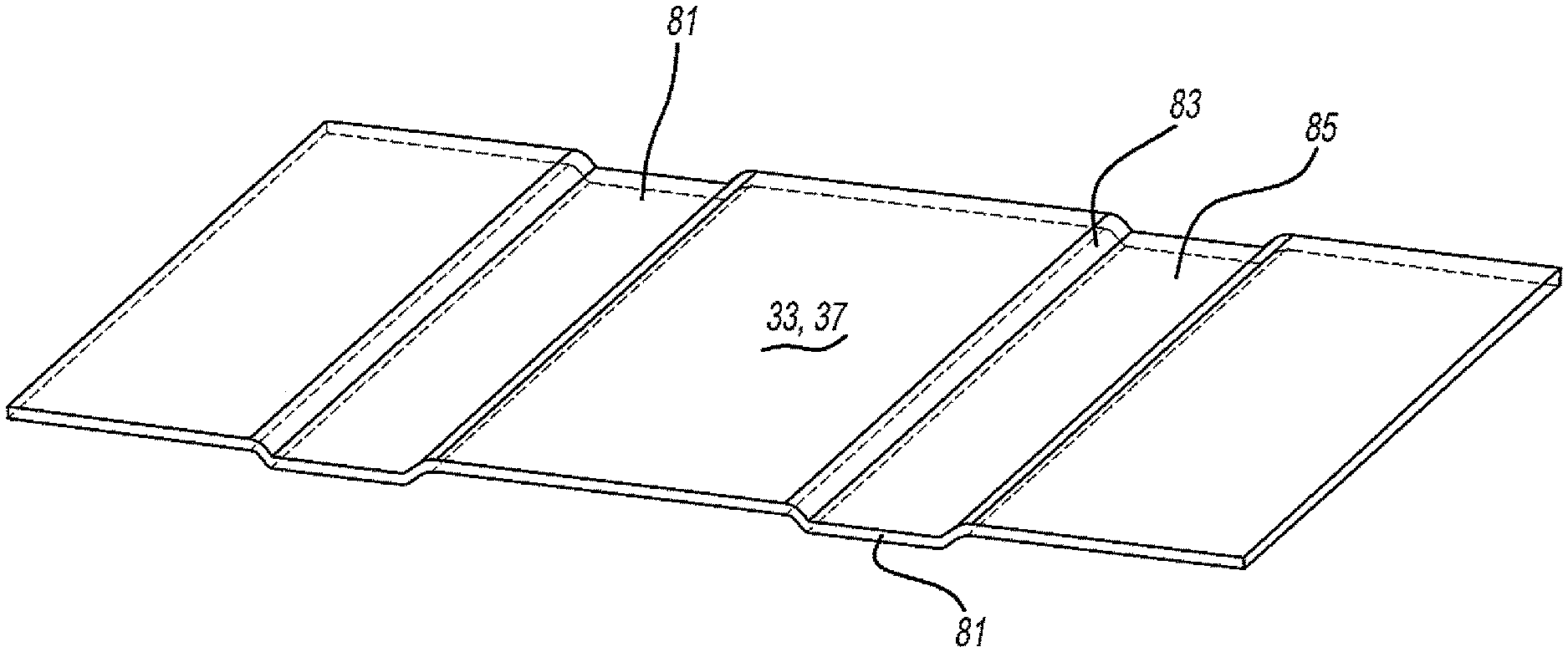
Another configuration of sandwich structure 31 is illustrated in FIGS. 6 and 8. In this embodiment, each outer face sheet 33 and 37 includes elongated grooves or ribs 81 each having a generally laterally widened U-cross-sectional shape defined by angular side walls 83 and a generally flat bottom wall 85 which is laterally greater than three times its depth d and more preferably at least five times its depth. Flat interior and exterior surfaces of each outer sheet connect between each groove 81 as with the prior embodiment. It is noteworthy that grooves 81 in this configuration are configured to generally matingly match and mirror the peak and ridge cross-sectional shapes and dimensions in a generally parallel manner, albeit the diagonal side walls 83 may have slightly different angles or curvatures than that of the transition between the adjacent ridges 45 to peaks 39. Gaps or spaces 77 are also present between grooves 81 and the adjacent interior ridges 45.
FIG. 9 shows another version of sandwich structure 31. Grooves or ribs 91 are of similar shape to those of FIG. 6, however, the present grooves 91 preferably have steeper side walls and the lateral width of their bottom walls is less than that of the prior embodiment. The rigidity and bending resistance of each groove 91 will thereby be somewhat different than that of groove 81. Gaps or spaces 77 are also present between grooves 91 and ridges 45.
Reference should now be made to FIGS. 10-13. In these embodiments, grooves or ribs 71', 81' and 91' are similar to those of the prior embodiments except that the bottom wall or surface of each groove directly or indirectly contacts against the adjacent ridge 45 spanning between peaks 39. If it directly contacts then there will be a sheet-to-sheet mating engagement. If there is indirect contact, however, an adhesive or structural foam layer may be present between the outer and core sheets. This contact advantageously increases compressive strength of the final assembled sandwich structure 31. Thus, with all of the embodiments disclosed herein, the grooves of the outer face sheets synergistically work with the patterned core sheet to enhance various load carrying, dent resistance and flexure resistance properties of the overall structure.
FIG. 16 shows another variation wherein any of the previously disclosed sandwich constructions are employed as one or more sections of a door 311, such as a movable garage door with multiples of adjacent sandwich panels hinged together. The sandwich may alternately be a wall 213, ceiling, floor 217 or a smaller door of building 215 like that shown in FIG. 15. In another configuration, the sandwich structure constitutes a panel used as a wall, ceiling, floor or door for a wheeled trailer 219 pulled by a truck 221, railroad box car or a cargo-holding container, as illustrated in FIG. 14. Moreover, the sandwich structure can be used as a bed or floor, or interior side wall of an automotive vehicle such as a pickup truck box. It should also be appreciated that any of the preceding embodiments and features thereof can be mixed and matched with any of the others depending upon the final product and processing characteristics desired.
While various embodiments of the present invention have been disclosed, it should also be appreciated that other variations may be employed. For example, welding, spot welding or blind riveting may be used instead of adhesive bonding between the adjacent sheets, but many of the present weight, cost and quick assembly advantages may not be realized. Additionally, other dimensions and shapes may be provided for the core sheet features, outer sheet grooves and the like, however, many of the manufacturing advantages and property strengths will not be achieved. It is also envisioned that a single elongated groove or rib may be used for each outer face sheet, shortened length grooves or ribs can be employed and/or non-linear (e.g., arcuately elongated) grooves or ribs may be utilized, although some of the core interengaging, alignment and performance characteristics disclosed herein may not be obtained. Variations are not to be regarded as a departure from the present disclosure, and all such modifications are intended to be included within the scope and spirit of the present invention.
* * * * *
D00000
D00001
D00002
D00003
D00004
D00005
D00006
D00007
XML
uspto.report is an independent third-party trademark research tool that is not affiliated, endorsed, or sponsored by the United States Patent and Trademark Office (USPTO) or any other governmental organization. The information provided by uspto.report is based on publicly available data at the time of writing and is intended for informational purposes only.
While we strive to provide accurate and up-to-date information, we do not guarantee the accuracy, completeness, reliability, or suitability of the information displayed on this site. The use of this site is at your own risk. Any reliance you place on such information is therefore strictly at your own risk.
All official trademark data, including owner information, should be verified by visiting the official USPTO website at www.uspto.gov. This site is not intended to replace professional legal advice and should not be used as a substitute for consulting with a legal professional who is knowledgeable about trademark law.