Minimally invasive repair of heart valve leaflets
Zentgraf , et al.
U.S. patent number 10,695,178 [Application Number 14/947,399] was granted by the patent office on 2020-06-30 for minimally invasive repair of heart valve leaflets. This patent grant is currently assigned to NeoChord, Inc.. The grantee listed for this patent is NeoChord, Inc.. Invention is credited to David J. Parins, Arun Saini, John Zentgraf.

View All Diagrams
| United States Patent | 10,695,178 |
| Zentgraf , et al. | June 30, 2020 |
Minimally invasive repair of heart valve leaflets
Abstract
A method of repairing a heart valve provides intravascular access for repair of a heart valve through a ventricular trans-septal approach. An external guide catheter can be inserted through a vein of a patient into the right ventricle via the right atrium. An internal guide catheter can be inserted through the external guide and can provide access to the septum for a puncture tool to create an opening through the septum to the left ventricle. The internal guide can then be advanced into the left ventricle and used to guide a deployment catheter that deploys a repair device onto the heart valve.
| Inventors: | Zentgraf; John (Minneapolis, MN), Parins; David J. (Corcoran, MN), Saini; Arun (Burnsville, MN) | ||||||||||
|---|---|---|---|---|---|---|---|---|---|---|---|
| Applicant: |
|
||||||||||
| Assignee: | NeoChord, Inc. (St. Louis Park,
MN) |
||||||||||
| Family ID: | 47260394 | ||||||||||
| Appl. No.: | 14/947,399 | ||||||||||
| Filed: | November 20, 2015 |
Prior Publication Data
| Document Identifier | Publication Date | |
|---|---|---|
| US 20160143737 A1 | May 26, 2016 | |
Related U.S. Patent Documents
| Application Number | Filing Date | Patent Number | Issue Date | ||
|---|---|---|---|---|---|
| 13486632 | Jun 1, 2012 | ||||
| 61492135 | Jun 1, 2011 | ||||
| Current U.S. Class: | 1/1 |
| Current CPC Class: | A61B 17/0467 (20130101); A61F 2/2457 (20130101); A61B 17/0057 (20130101); A61B 17/0487 (20130101); A61B 17/0482 (20130101); A61B 17/0469 (20130101); A61B 2017/06042 (20130101); A61B 2017/00243 (20130101); A61B 2017/0456 (20130101); A61B 2017/0496 (20130101); A61F 2250/0012 (20130101); A61B 2017/00606 (20130101) |
| Current International Class: | A61F 2/24 (20060101); A61B 17/00 (20060101); A61B 17/04 (20060101); A61B 17/06 (20060101) |
References Cited [Referenced By]
U.S. Patent Documents
| 2751908 | June 1956 | Wallace |
| 3667474 | June 1972 | Lapkin |
| 3842840 | October 1974 | Schweizer |
| 4258716 | March 1981 | Sutherland |
| 4351345 | September 1982 | Carney |
| 4836204 | June 1989 | Landymore et al. |
| 4935027 | June 1990 | Yoon |
| 4957498 | September 1990 | Caspari et al. |
| 4967498 | September 1990 | Caspari |
| 4960424 | October 1990 | Grooters |
| 4967798 | November 1990 | Hammer |
| 4972874 | November 1990 | Jackson |
| 5053013 | October 1991 | Ensminger |
| 5059201 | October 1991 | Asnis |
| 5211650 | May 1993 | Noda |
| 5297536 | March 1994 | Wilk |
| 5304185 | April 1994 | Taylor |
| 5312423 | May 1994 | Rosenbluth et al. |
| 5336229 | August 1994 | Noda |
| 5383877 | January 1995 | Clarke |
| 5431666 | July 1995 | Sauer et al. |
| 5452733 | September 1995 | Sterman |
| 5474519 | December 1995 | Bloomer |
| 5547455 | August 1996 | McKenna et al. |
| 5556411 | September 1996 | Taoda et al. |
| 5571215 | November 1996 | Sterman |
| 5601578 | February 1997 | Murphy |
| 5626607 | May 1997 | Malecki |
| 5653716 | August 1997 | Malo et al. |
| 5665100 | September 1997 | Yoon |
| 5667472 | September 1997 | Finn et al. |
| 5667473 | September 1997 | Finn et al. |
| 5667478 | September 1997 | McFarlin et al. |
| 5693091 | December 1997 | Larson, Jr. et al. |
| 5728113 | March 1998 | Sherts |
| 5762458 | June 1998 | Wang et al. |
| 5762613 | June 1998 | Sutton et al. |
| 5766163 | June 1998 | Mueller et al. |
| 5772597 | June 1998 | Goldberger et al. |
| 5772672 | June 1998 | Toy et al. |
| 5785658 | July 1998 | Benaron et al. |
| 5797960 | August 1998 | Stevens et al. |
| 5830231 | November 1998 | Geiges, Jr. |
| 5839639 | November 1998 | Sauer et al. |
| 5897564 | April 1999 | Schulze et al. |
| 5908428 | June 1999 | Scirica et al. |
| 5908429 | June 1999 | Yoon |
| 5919128 | July 1999 | Fitch |
| 5961440 | October 1999 | Schweich, Jr. |
| 5972004 | October 1999 | Williamson et al. |
| 5972030 | October 1999 | Garrison et al. |
| 5984939 | November 1999 | Yoon |
| 5993466 | November 1999 | Yoon |
| 5993467 | November 1999 | Yoon |
| 6022360 | February 2000 | Reimels et al. |
| 6045497 | April 2000 | Schweich, Jr. |
| 6050936 | April 2000 | Schweich, Jr. |
| 6053933 | April 2000 | Balazs et al. |
| 6059715 | May 2000 | Schweich, Jr. |
| 6077214 | June 2000 | Mortier et al. |
| 6117144 | September 2000 | Nobles et al. |
| 6129683 | October 2000 | Sutton et al. |
| 6149660 | November 2000 | Laufer et al. |
| 6152934 | November 2000 | Harper et al. |
| 6162168 | December 2000 | Schweich, Jr. |
| 6162233 | December 2000 | Williamson |
| 6165119 | December 2000 | Schweich, Jr. |
| 6165120 | December 2000 | Schweich, Jr. |
| 6165183 | December 2000 | Kuehn et al. |
| 6178346 | January 2001 | Amundson et al. |
| 6183411 | February 2001 | Mortier et al. |
| 6190357 | February 2001 | Ferrari et al. |
| 6234079 | May 2001 | Chertkow |
| 6234995 | May 2001 | Peacock, III |
| 6245079 | June 2001 | Nobles et al. |
| 6260552 | July 2001 | Mortier et al. |
| 6261222 | July 2001 | Schweich, Jr. |
| 6264602 | July 2001 | Mortier et al. |
| 6269819 | August 2001 | Oz et al. |
| 6270508 | August 2001 | KlIeman et al. |
| 6283993 | September 2001 | Cosgrove et al. |
| 6312447 | November 2001 | Grimes |
| 6332863 | December 2001 | Schweich, Jr. et al. |
| 6332864 | December 2001 | Schweich, Jr. et al. |
| 6332893 | December 2001 | Mortier et al. |
| 6355050 | March 2002 | Andreas et al. |
| 6401720 | June 2002 | Stevens et al. |
| 6402679 | June 2002 | Mortier et al. |
| 6402680 | June 2002 | Mortier et al. |
| 6402781 | June 2002 | Langberg et al. |
| 6406420 | June 2002 | McCarthy et al. |
| 6419626 | July 2002 | Yoon |
| 6436107 | August 2002 | Wang et al. |
| 6443922 | September 2002 | Roberts et al. |
| 6451054 | September 2002 | Stevens |
| 6461366 | October 2002 | Seguin |
| 6508777 | January 2003 | Macoviak et al. |
| 6514194 | February 2003 | Schweich, Jr. et al. |
| 6533796 | March 2003 | Sauer et al. |
| 6537198 | March 2003 | Vidlund et al. |
| 6537314 | March 2003 | Langberg et al. |
| 6551331 | April 2003 | Nobles et al. |
| 6558416 | May 2003 | Cosgrove et al. |
| 6562052 | May 2003 | Nobles et al. |
| 6564805 | May 2003 | Garrison et al. |
| 6582388 | June 2003 | Coleman et al. |
| 6585727 | July 2003 | Cashman et al. |
| 6589160 | July 2003 | Schweich, Jr. et al. |
| 6602288 | August 2003 | Cosgrove et al. |
| 6616684 | September 2003 | Vidlund et al. |
| 6619291 | September 2003 | Hlavka et al. |
| 6622730 | September 2003 | Ekvall et al. |
| 6626917 | September 2003 | Craig |
| 6626930 | September 2003 | Allen et al. |
| 6629534 | October 2003 | St. Goar et al. |
| 6629921 | October 2003 | Schweich, Jr. et al. |
| 6629984 | October 2003 | Chan |
| 6645205 | November 2003 | Ginn |
| 6679268 | January 2004 | Stevens et al. |
| 6692605 | February 2004 | Kerr et al. |
| 6695866 | February 2004 | Kuehn et al. |
| 6709456 | March 2004 | Langberg et al. |
| 6718985 | April 2004 | Hlavka et al. |
| 6723038 | April 2004 | Schroeder et al. |
| 6733509 | May 2004 | Nobles et al. |
| 6740107 | May 2004 | Loeb et al. |
| 6743239 | June 2004 | Kuehn |
| 6746471 | June 2004 | Mortier et al. |
| 6752713 | June 2004 | Johnson, Jr. |
| 6752813 | June 2004 | Goldfarb et al. |
| 6755777 | June 2004 | Schweich, Jr. et al. |
| 6764510 | July 2004 | Vidlund et al. |
| 6770083 | August 2004 | Seguin |
| 6770084 | August 2004 | Bain et al. |
| 6793618 | September 2004 | Schweich, Jr. et al. |
| 6802860 | October 2004 | Cosgrove et al. |
| 6808488 | October 2004 | Mortier et al. |
| 6810882 | November 2004 | Langberg et al. |
| 6840246 | January 2005 | Downing |
| 6858003 | February 2005 | Evans et al. |
| 6875224 | April 2005 | Grimes |
| 6893448 | May 2005 | O'Quinn et al. |
| 6908424 | June 2005 | Mortier et al. |
| 6918917 | July 2005 | Nguyen et al. |
| 6921407 | July 2005 | Nguyen et al. |
| 6929715 | August 2005 | Fladda et al. |
| 6936054 | August 2005 | Chu |
| 6955175 | October 2005 | Stevens et al. |
| 6962605 | November 2005 | Cosgrove et al. |
| 6978176 | December 2005 | Lattouf |
| 6986775 | January 2006 | Morales et al. |
| 6989028 | January 2006 | Lashinski et al. |
| 6991635 | January 2006 | Takamoto et al. |
| 6997950 | February 2006 | Chawla |
| 7004176 | February 2006 | Lau |
| 7004952 | February 2006 | Nobles et al. |
| 7011669 | March 2006 | Kimblad |
| 7044905 | May 2006 | Vidlund et al. |
| 7048754 | May 2006 | Martin et al. |
| 7077862 | July 2006 | Vidlund et al. |
| 7083628 | August 2006 | Bachman |
| 7083638 | August 2006 | Foerster |
| 7090686 | August 2006 | Nobles et al. |
| 7094244 | August 2006 | Schreck |
| 7100614 | September 2006 | Stevens et al. |
| 7112207 | September 2006 | Allen et al. |
| 7112219 | September 2006 | Vidlund et al. |
| 7115110 | October 2006 | Frazier et al. |
| 7118583 | October 2006 | O'Quinn et al. |
| 7122040 | October 2006 | Hill et al. |
| 7179291 | February 2007 | Rourke et al. |
| 7186264 | March 2007 | Liddicoat et al. |
| 7189199 | March 2007 | McCarthy et al. |
| 7217240 | May 2007 | Snow |
| 7226467 | June 2007 | Lucatero et al. |
| 7247134 | July 2007 | Vidlund et al. |
| 7250028 | July 2007 | Julian et al. |
| 7288097 | October 2007 | Seguin |
| 7294148 | November 2007 | McCarthy |
| 7381210 | June 2008 | Zarbatany et al. |
| 7464712 | December 2008 | Oz et al. |
| 7563267 | July 2009 | Goldfarb et al. |
| 7563273 | July 2009 | Goldfarb et al. |
| 7604646 | October 2009 | Goldfarb et al. |
| 7608091 | October 2009 | Goldfarb et al. |
| 7635386 | December 2009 | Gammie |
| 7666204 | February 2010 | Thornton et al. |
| 7815654 | October 2010 | Chu |
| 7879048 | February 2011 | Bain et al. |
| 7887552 | February 2011 | Bachman |
| 8465500 | June 2013 | Speziali |
| 8758393 | June 2014 | Zentgraf |
| 2001/0005787 | June 2001 | Oz |
| 2001/0016675 | August 2001 | Mortier et al. |
| 2001/0021872 | September 2001 | Bailey et al. |
| 2002/0013571 | January 2002 | Goldfarb et al. |
| 2002/0029080 | March 2002 | Mortier et al. |
| 2002/0049402 | April 2002 | Peacock, III |
| 2002/0077524 | June 2002 | Schweich, Jr. |
| 2002/0169359 | November 2002 | McCarthy |
| 2002/0173694 | November 2002 | Mortier et al. |
| 2002/0183766 | December 2002 | Seguin |
| 2002/0183787 | December 2002 | Wahr |
| 2003/0004562 | January 2003 | DiCarlo |
| 2003/0032979 | February 2003 | Mortier et al. |
| 2003/0050529 | March 2003 | Vidlund et al. |
| 2003/0050693 | March 2003 | Quijano |
| 2003/0078600 | April 2003 | O'Quinn et al. |
| 2003/0105519 | June 2003 | Fasol |
| 2003/0130731 | July 2003 | Vidlund et al. |
| 2003/0166992 | September 2003 | Schweich, Jr. |
| 2003/0167071 | September 2003 | Martin et al. |
| 2003/0171641 | September 2003 | Schweich, Jr. |
| 2003/0181928 | September 2003 | Vidlund et al. |
| 2003/0187457 | October 2003 | Weber |
| 2003/0195529 | October 2003 | Takamoto et al. |
| 2003/0199975 | October 2003 | Gabbay |
| 2004/0003819 | January 2004 | St. Goar |
| 2004/0030382 | February 2004 | St. Goar |
| 2004/0039442 | February 2004 | St. Goar |
| 2004/0044350 | March 2004 | Martin et al. |
| 2004/0044365 | March 2004 | Bachman |
| 2004/0049207 | March 2004 | Goldfarb et al. |
| 2004/0049552 | March 2004 | Motoyama |
| 2004/0087975 | May 2004 | Lucatero et al. |
| 2004/0087978 | May 2004 | Velez et al. |
| 2004/0092962 | May 2004 | Thornton et al. |
| 2004/0097805 | May 2004 | Verard et al. |
| 2004/0116767 | June 2004 | Lebovic |
| 2004/0122448 | June 2004 | Levine |
| 2004/0127983 | July 2004 | Mortier et al. |
| 2004/0133063 | July 2004 | McCarthy et al. |
| 2004/0167374 | August 2004 | Schweich et al. |
| 2004/0167539 | August 2004 | Kuehn et al. |
| 2004/0225300 | November 2004 | Goldfarb et al. |
| 2004/0225304 | November 2004 | Vidlund et al. |
| 2004/0236353 | November 2004 | Bain et al. |
| 2004/0236354 | November 2004 | Seguin |
| 2004/0243229 | December 2004 | Vidlund et al. |
| 2004/0267083 | December 2004 | McCarthy |
| 2005/0004668 | January 2005 | Aklog et al. |
| 2005/0021055 | January 2005 | Toubia et al. |
| 2005/0021056 | January 2005 | St. Goar |
| 2005/0021057 | January 2005 | St. Goar |
| 2005/0033446 | February 2005 | Deem et al. |
| 2005/0044365 | February 2005 | Bachman |
| 2005/0065396 | March 2005 | Mortier et al. |
| 2005/0075723 | April 2005 | Schroeder et al. |
| 2005/0075727 | April 2005 | Wheatley |
| 2005/0101975 | May 2005 | Nguyen et al. |
| 2005/0125011 | June 2005 | Spence et al. |
| 2005/0131277 | June 2005 | Schweich, Jr. |
| 2005/0131533 | June 2005 | Alfieri et al. |
| 2005/0143620 | June 2005 | Mortier et al. |
| 2005/0148815 | July 2005 | Mortier et al. |
| 2005/0149014 | July 2005 | Hauck et al. |
| 2005/0154402 | July 2005 | Sauer et al. |
| 2005/0165419 | July 2005 | Sauer et al. |
| 2005/0171601 | August 2005 | Cosgrove |
| 2005/0216039 | September 2005 | Lederman |
| 2005/0240202 | October 2005 | Shennib et al. |
| 2005/0251187 | November 2005 | Beane et al. |
| 2006/0020275 | January 2006 | Goldfarb et al. |
| 2006/0036317 | February 2006 | Vidlund et al. |
| 2006/0041306 | February 2006 | Vidlund et al. |
| 2006/0052868 | March 2006 | Mortier et al. |
| 2006/0058871 | March 2006 | Zakay et al. |
| 2006/0074484 | April 2006 | Huber |
| 2006/0074485 | April 2006 | Realyvasquez |
| 2006/0089671 | April 2006 | Goldfarb et al. |
| 2006/0100699 | May 2006 | Vidlund et al. |
| 2006/0127509 | June 2006 | Eckman |
| 2006/0135993 | June 2006 | Seguin |
| 2006/0149123 | July 2006 | Vidlund et al. |
| 2006/0161040 | July 2006 | McCarthy |
| 2006/0161193 | July 2006 | Beane et al. |
| 2006/0184203 | August 2006 | Martin et al. |
| 2006/0195012 | August 2006 | Mortier et al. |
| 2006/0195134 | August 2006 | Crittenden |
| 2006/0195183 | August 2006 | Navia et al. |
| 2006/0241340 | October 2006 | Vidlund |
| 2006/0287657 | December 2006 | Bachman |
| 2007/0002627 | January 2007 | Youn |
| 2007/0027451 | February 2007 | Desinger et al. |
| 2007/0049952 | March 2007 | Weiss |
| 2007/0050022 | March 2007 | Vidlund et al. |
| 2007/0055303 | March 2007 | Vidlund et al. |
| 2007/0088375 | April 2007 | Beane et al. |
| 2007/0100356 | May 2007 | Lucatero et al. |
| 2007/0112244 | May 2007 | McCarthy |
| 2007/0118154 | May 2007 | Crabtree |
| 2007/0118155 | May 2007 | Goldfarb et al. |
| 2007/0129737 | June 2007 | Goldfarb et al. |
| 2007/0179511 | August 2007 | Paolitto |
| 2007/0197858 | August 2007 | Goldfarb et al. |
| 2007/0203391 | August 2007 | Bloom et al. |
| 2007/0232941 | October 2007 | Rabinovich |
| 2007/0239272 | October 2007 | Navia et al. |
| 2007/0265643 | November 2007 | Beane et al. |
| 2007/0299468 | December 2007 | Viola |
| 2008/0004485 | January 2008 | Moreschi |
| 2008/0027468 | January 2008 | Fenton |
| 2008/0051703 | February 2008 | Thornton et al. |
| 2008/0065011 | March 2008 | Marchand et al. |
| 2008/0065156 | March 2008 | Hauser et al. |
| 2008/0065205 | March 2008 | Nguyen et al. |
| 2008/0091059 | April 2008 | Machold |
| 2008/0091264 | April 2008 | Machold |
| 2008/0097482 | April 2008 | Bain et al. |
| 2008/0097489 | April 2008 | Goldfarb et al. |
| 2008/0109069 | May 2008 | Coleman et al. |
| 2008/0125860 | May 2008 | Webler |
| 2008/0125861 | May 2008 | Webler et al. |
| 2008/0167714 | July 2008 | St. Goar |
| 2008/0183194 | July 2008 | Goldfarb et al. |
| 2008/0188873 | August 2008 | Speziali |
| 2008/0195200 | August 2008 | Vidlund et al. |
| 2008/0208006 | August 2008 | Farr |
| 2008/0228223 | September 2008 | Alkhatib |
| 2008/0243245 | October 2008 | Thamber et al. |
| 2009/0105729 | April 2009 | Zentgraf |
| 2009/0105751 | April 2009 | Zentgraf |
| 2009/0131880 | May 2009 | Speziali et al. |
| 2009/0156995 | June 2009 | Martin et al. |
| 2009/0163934 | June 2009 | Raschdorf, Jr. |
| 2009/0192598 | July 2009 | Lattouf et al. |
| 2009/0259304 | October 2009 | O'Beirne et al. |
| 2010/0030061 | February 2010 | Canfield et al. |
| 2010/0042147 | February 2010 | Janovsky et al. |
| 2010/0160726 | June 2010 | Windheuser |
| 2010/0174297 | July 2010 | Speziali |
| 2010/0185172 | July 2010 | Fabro |
| 2010/0217283 | August 2010 | St. Goar |
| 2010/0298929 | November 2010 | Thornton |
| 2011/0011917 | January 2011 | Loulmet |
| 2012/0184971 | July 2012 | Zentgraf et al. |
| 2013/0035757 | February 2013 | Zentgraf et al. |
| 2013/0150710 | June 2013 | Zentgraf et al. |
| 2014/0039324 | February 2014 | Speziali |
| 1039851 | Jul 2005 | EP | |||
| 1637091 | Mar 2006 | EP | |||
| 1845861 | Oct 2007 | EP | |||
| 1408850 | Sep 2009 | EP | |||
| 06142114 | May 1994 | JP | |||
| 2004-531337 | Oct 2004 | JP | |||
| 2007-535342 | Dec 2007 | JP | |||
| WO 1999/00059 | Jan 1999 | WO | |||
| WO 1999/30647 | Jun 1999 | WO | |||
| WO 2000/06026 | Feb 2000 | WO | |||
| WO 2000/06027 | Feb 2000 | WO | |||
| WO 2000/06028 | Feb 2000 | WO | |||
| WO 2000/16700 | Mar 2000 | WO | |||
| WO 2001/66018 | Sep 2001 | WO | |||
| WO 2001/95809 | Dec 2001 | WO | |||
| WO 2003/001893 | Jan 2003 | WO | |||
| WO 2003/059209 | Jul 2003 | WO | |||
| WO 2003/082157 | Oct 2003 | WO | |||
| WO 2003/082158 | Oct 2003 | WO | |||
| WO 2004/021893 | Mar 2004 | WO | |||
| WO 2004/043265 | May 2004 | WO | |||
| WO 2005/039428 | May 2005 | WO | |||
| WO 2005/087140 | Sep 2005 | WO | |||
| WO 2005/094525 | Oct 2005 | WO | |||
| WO 2006/012750 | Feb 2006 | WO | |||
| WO 2006/032051 | Mar 2006 | WO | |||
| WO 2006/065966 | Jun 2006 | WO | |||
| WO 2006/078694 | Jul 2006 | WO | |||
| WO 2006/116310 | Nov 2006 | WO | |||
| WO 2006/127509 | Nov 2006 | WO | |||
| WO 2007/002627 | Jan 2007 | WO | |||
| WO 2007/027451 | Mar 2007 | WO | |||
| WO 2007/062128 | May 2007 | WO | |||
| WO 2007/081418 | Jul 2007 | WO | |||
| WO 2007/117612 | Oct 2007 | WO | |||
| WO 2008/010738 | Jan 2008 | WO | |||
| WO 2009/052528 | Apr 2009 | WO | |||
| WO 2011/070477 | Jun 2011 | WO | |||
| WO 2011/137336 | Nov 2011 | WO | |||
| WO 2012/167120 | Dec 2012 | WO | |||
Other References
|
Interactive Cardio Vascular and Thoracic Surgery; Abstracts; Suppl 3 to vol. 7 (Sep. 2008) 52 pages. cited by applicant . Machine translation of JP 06142114. cited by applicant . Port Access System for Mitral Valve Repair Proves Its Value in Study; MedGadget Jul. 9, 2009 (2 pages). cited by applicant . PCT/US2012/040512, filed Jun. 1, 2012, Written Opinion dated Dec. 21, 2012, 5 pages. cited by applicant . PCT/US2012/040512, filed Jun. 1, 2012, Search Report dated Dec. 21, 2012, 6 pages. cited by applicant . PCT/US2012/067563, International Preliminary Examination Report, dated Jun. 3, 2014, 9 pages. cited by applicant . Extended European Search Report, EP 06718728.6, dated Nov. 11, 2009, 7 pages. cited by applicant . PCT International Preliminary Report on Patentability for PCT/US2008/080560, dated Apr. 29, 2010, 7 pages. cited by applicant . PCT International Search Report and Written Opinion, PCT/US06/01699, dated May 6, 2008, 5 pages. cited by applicant . European Search Report, EP 08839048.9, dated Sep. 16, 2010, 7 pages. cited by applicant . PCT International Search Report, PCT/US2008/080560, dated Aug. 25, 2009, 3 pages. cited by applicant . PCT/US2011/067884, Search Report/Written Opinion dated Jul. 30, 2011, 11 pages. cited by applicant . EP Application No. 12792116.1, Extended Search Report dated Jan. 8, 2015, 7 pages. cited by applicant . JP Application No. 2014-513757, Notification of Refusal dated Mar. 7, 2016, translation as obtained through Global Dossier, 3 pages. cited by applicant . AU Application No. 2012261998, Patent Examination Report No. 1, dated Mar. 3, 2016, 4 pages. cited by applicant . CN Application No. 201280038285.7, First Office Action dated Aug. 4, 2015, translation as obtained through Global Dossier, 6 pages. cited by applicant . Application and File History for U.S. Appl. No. 11/813,695, filed Jul. 11, 2007, now U.S. Pat. No. 8,465,500. Inventor: Speziali. cited by applicant . Application and File History for U.S. Appl. No. 12,254,808, filed Oct. 20, 2008. Inventor: Zentgraf. cited by applicant . Application and File History for U.S. Appl. No. 12/254,807, filed Oct. 20, 2008, now U.S. Pat. No. 8,758,393. Inventor: Zentgraf. cited by applicant . Application and File History for U.S. Appl. No. 12/709,220, filed Feb. 19, 2010. Inventor: Speziali. cited by applicant . Application and File History for U.S. Appl. No. 13/898,709, filed May 21, 2013. Inventor: Speziali. cited by applicant . Application and File History for U.S. Appl. No. 13/339,865, filed Dec. 29, 2011. Inventors: Zentgraf et al. cited by applicant . Application and File History for U.S. Appl. No. 13/340,185, filed Dec. 29, 2011. Inventors: Zentgraf et al. cited by applicant . Application and File History for U.S. Appl. No. 13/486,632, filed Jun. 1, 2012. Inventor Zentgraf et al. cited by applicant . Application and File History for U.S. Appl. No. 13/692,027, filed Dec. 3, 2012. Inventors: Zentgraf et al. cited by applicant . Application and File History for U.S. Appl. No. 14/310,069, filed Jun. 20, 2014. Inventor: Zentgraf. cited by applicant . EP Application No. 12792116.1, Communication Pursuant to Article 94(3) EPC, dated May 24, 2018, 7 pages. cited by applicant . Canadian Application No. 2,837,206, Office Action dated Apr. 18, 2018, 3 pages. cited by applicant. |
Primary Examiner: Ho; Tan-Uyen T
Assistant Examiner: Highland; Rachel S
Attorney, Agent or Firm: Patterson Thuente Pedersen, P.A.
Parent Case Text
RELATED APPLICATION
This application is a continuation of application Ser. No. 13/486,632 filed Jun. 1, 2012, which claims the benefit of U.S. Provisional Application No. 61/492,135 filed Jun. 1, 2011, each of which is hereby incorporated herein by reference.
Claims
The invention claimed is:
1. A method of repairing a mitral valve in a beating heart of a patient, comprising: inserting an external guide catheter through a vein of a patient and into a right atrium of a heart of a patient; advancing the external guide catheter into a right ventricle of the patient's heart; advancing an internal guide catheter through the external guide catheter and advancing the internal guide catheter into the right ventricle; puncturing an interventricular septum in the patient's heart to create an opening between the right ventricle and the left ventricle; advancing the internal guide catheter through the opening in the interventricular septum and into the left ventricle; advancing a deployment catheter through the internal guide catheter and advancing the deployment catheter through the interventricular septum and into the left ventricle; deploying a suture onto a mitral valve leaflet with the deployment catheter; advancing a sealing device through the internal guide catheter to the interventricular septum; and positioning the sealing device within the opening in the interventricular septum with the suture extending between the mitral valve leaflet that the suture is deployed onto and the sealing device.
2. The method of claim 1, wherein the step of positioning the sealing device within the opening in the interventricular septum is done after the step of deploying a suture onto the mitral valve.
3. The method of claim 1, wherein the step of deploying a suture onto the mitral valve with the deployment catheter includes: capturing a mitral valve leaflet with a clamping mechanism of the deployment catheter; and inserting the suture through the mitral valve leaflet with a needle of the deployment catheter.
4. The method of claim 1, further comprising: positioning the sealing device within the opening in the interventricular septum such that a proximal end of the suture extends from the mitral valve through the interventricular septum.
5. The method of claim 4, further comprising: advancing a cutting catheter having a cutting tool through the internal guide catheter to the interventricular septum; and cutting the suture in the right ventricle adjacent the sealing device.
6. The method of claim 1, further comprising: threading a proximal end of the suture through an anchoring device; advancing the anchoring device through the internal guide catheter to the opening in the interventricular septum; and positioning the anchoring device with the sealing device within the interventricular septum such that the suture extends between the mitral valve and the opening in the interventricular septum.
7. A method of repairing a mitral valve in a beating heart of a patient comprising: intravenously accessing a right ventricle of a beating heart of a patient; creating an opening though an interventricular septum of the patient's heart between the right ventricle and the left ventricle; positioning a deployment catheter containing a repair device in the left ventricle by extending the deployment catheter through the opening in the interventricular septum; deploying a suture onto a mitral valve by drawing the suture through a mitral valve leaflet with a needle; withdrawing the deployment catheter from the left ventricle through the interventricular septum.
8. The method of claim 7, further comprising: positioning a sealing device within the opening in the interventricular septum; and connecting a locking device with the sealing device.
9. The method of claim 7, further comprising: positioning a sealing device within the opening in the interventricular septum such that the suture extends from the mitral valve in the left ventricle through the interventricular septum and into the right ventricle.
10. The method of claim 9, further comprising: advancing an anchoring device to the interventricular septum; and locking a position of the suture with respect to the sealing device with the anchoring device.
11. The method of claim 10, further comprising: advancing a cutting tool to the interventricular septum; and cutting the suture in the right ventricle adjacent the sealing device.
12. A method, comprising: providing a mitral valve repair system, the system including a side exiting external guide catheter, an internal guide catheter, a septal puncture tool and a deployment catheter; providing instructions for deploying a suture onto a mitral valve of a beating heart of a patient with the mitral valve repair system, the instructions comprising: inserting the side exiting external guide catheter through a vein of the patient and into a right atrium of the heart of the patient; advancing the external guide catheter into the right ventricle of the patient's heart; advancing the internal guide catheter through the external guide catheter and advancing the internal guide catheter into the right ventricle; directing the septal puncture tool adjacent and generally transversely to the ventricular wall via the side exiting external guide catheter; puncturing an interventricular septum in the patient's heart with the septal puncture tool to create an opening between the right ventricle and the left ventricle; advancing the internal guide catheter through the opening in the interventricular septum into the left ventricle; advancing the deployment catheter through the internal guide catheter and advancing the deployment catheter through the interventricular septum and into the left ventricle; and deploying a suture onto the mitral valve with the deployment catheter.
13. The method of claim 12, wherein the mitral valve repair system further includes a sealing device and the instructions further comprise: advancing the sealing device through the internal guide catheter to the interventricular septum; and positioning the sealing device within the opening in the interventricular septum.
14. The method of claim 12, wherein the step of deploying a suture onto the mitral valve with the deployment catheter includes: capturing a mitral valve leaflet with a clamping mechanism of the deployment catheter; and inserting the suture through the mitral valve leaflet with a needle of the deployment catheter.
15. The method of claim 12, wherein the mitral valve repair system further includes a sealing device and the instructions further comprise: advancing the sealing device through the internal guide catheter to the interventricular septum; and positioning the sealing device within the opening in the interventricular septum such that a proximal end of the suture extends from the mitral valve through the interventricular septum.
16. The method of claim 15, wherein the mitral valve repair system further comprises a cutting catheter having a cutting tool and the instructions further comprise: advancing the cutting catheter and cutting tool through the internal guide catheter to the interventricular septum; and cutting the suture in the right ventricle adjacent the sealing device.
17. The method of claim 12, wherein the mitral valve repair system further includes an anchoring device and the instructions further comprise: threading a proximal end of the suture through the anchoring device; advancing the anchoring device through the internal guide catheter to the opening in the interventricular septum; and positioning the anchoring device within the interventricular septum such that the suture extends between the mitral valve and the opening in the interventricular septum.
Description
FIELD OF THE INVENTION
The present invention relates to minimally invasive delivery of a suture. More particularly, the present invention relates to attaching the suture as an artificial chordae tendineae to a flailing or prolapsing leaflet in a beating heart via an intravascular ventricular septal approach.
BACKGROUND OF THE INVENTION
Various types of surgical procedures are currently performed to investigate, diagnose, and treat diseases of the heart and the great vessels of the thorax. Such procedures include repair and replacement of mitral, aortic, and other heart valves, repair of atrial and ventricular septal defects, pulmonary thrombectomy, treatment of aneurysms, electrophysiological mapping and ablation of the myocardium, and other procedures in which interventional devices are introduced into the interior of the heart or a great vessel.
Using current techniques, many of these procedures require a gross thoracotomy, usually in the form of a median sternotomy, to gain access into the patient's thoracic cavity. A saw or other cutting instrument is used to cut the sternum longitudinally, allowing two opposing halves of the anterior or ventral portion of the rib cage to be spread apart. A large opening into the thoracic cavity is thus created, through which the surgical team may directly visualize and operate upon the heart and other thoracic contents.
Surgical intervention within the heart by a thoracotomy generally requires isolation of the heart and coronary blood vessels from the remainder of the arterial system, and arrest of cardiac function (an "open heart" procedure). Usually, the heart is isolated from the arterial system by introducing an external aortic cross-clamp through a sternotomy and applying it to the aorta between the brachiocephalic artery and the coronary ostia. Cardioplegic fluid is then injected into the coronary arteries, either directly into the coronary ostia or through a puncture in the aortic root, so as to arrest cardiac function. In some cases, cardioplegic fluid is injected into the coronary sinus for retrograde perfusion of the myocardium. The patient is placed on cardiopulmonary bypass to maintain peripheral circulation of oxygenated blood.
Of particular interest to the present invention are open heart procedures for surgical treatment of heart valves, especially the mitral and aortic valves. According to recent estimates, more than 79,000 patients are diagnosed with aortic and mitral valve disease in U.S. hospitals each year. More than 49,000 mitral valve or aortic valve replacement procedures are performed annually in the U.S., along with a significant number of heart valve repair procedures.
Various surgical techniques may be used during an open heart procedure to repair a diseased or damaged valve, including annuloplasty (contracting the valve annulus), quadrangular resection (narrowing the valve leaflets), commissurotomy (cutting the valve commissures to separate the valve leaflets), shortening mitral or tricuspid valve chordae tendonae, reattachment of severed mitral or tricuspid valve chordae tendonae or papillary muscle tissue, and decalcification of valve and annulus tissue. Alternatively, the valve may be replaced by excising the valve leaflets of the natural valve and securing a replacement valve in the valve position, usually by suturing the replacement valve to the natural valve annulus. Various types of replacement valves are in current use, including mechanical and biological prostheses, homografts, and allografts.
The mitral valve, located between the left atrium and left ventricle of the heart, is most easily reached through the wall of the left atrium, which normally resides on the posterior side of the heart, opposite the side of the heart that is exposed by a median sternotomy. Therefore, to access the mitral valve via a sternotomy, the heart is rotated to bring the left atrium into a position accessible through the sternotomy. An opening, or atriotomy, is then made in the left atrium, anterior to the right pulmonary veins. The atriotomy is retracted by means of sutures or a retraction device, exposing the mitral valve directly posterior to the atriotomy. One of the aforementioned techniques may then be used to repair or replace the valve.
An alternative technique for mitral valve access during an open heart procedure may be used when a median sternotomy and/or rotational manipulation of the heart are/is undesirable. In this technique, a large incision is made in the right lateral side of the chest, usually in the region of the fifth intercostal space. One or more ribs may be removed from the patient, and other ribs near the incision are retracted outward to create a large opening onto the thoracic cavity. The left atrium is then exposed on the posterior side of the heart, and an atriotomy is formed in the wall of the left atrium, through which the mitral valve may be accessed for repair or replacement.
The mitral and tricuspid valves inside the human heart include an orifice (annulus), two (for the mitral) or three (for the tricuspid) leaflets and a subvalvular apparatus. The subvalvular apparatus includes multiple chordae tendineae, which connect the mobile valve leaflets to muscular structures (papillary muscles) inside the ventricles. Rupture or elongation of the chordae tendineae results in partial or generalized leaflet prolapse, which causes mitral (or tricuspid) valve regurgitation. A commonly used technique to surgically correct mitral valve regurgitation is the implantation of artificial chordae (usually 4-0 or 5-0 Gore-Tex sutures) between the prolapsing segment of the valve and the papillary muscle. This open heart operation is generally carried out through a median sternotomy and requires cardiopulmonary bypass with aortic cross-clamp and cardioplegic arrest of the heart.
Using such open heart techniques, the large opening provided by a median sternotomy or right thoracotomy enables the surgeon to see the mitral valve directly through the left atriotomy, and to position his or her hands within the thoracic cavity in close proximity to the exterior of the heart for manipulation of surgical instruments, removal of excised tissue, and/or introduction of a replacement valve through the atriotomy for attachment within the heart. However, these invasive open heart procedures produce a high degree of trauma, a significant risk of complications, an extended hospital stay, and a painful recovery period for the patient. Moreover, while heart valve surgery produces beneficial results for many patients, numerous others who might benefit from such surgery are unable or unwilling to undergo the trauma and risks of current techniques.
One alternative to open heart surgery is a robotically guided, thoracoscopically assisted cardiotomy procedure marketed under the tradename of the DaVinci.RTM. system. Instead of requiring a sternotomy, the DaVinci.RTM. system uses a minimally invasive approach guided by camera visualization and robotic techniques. Unfortunately, the DaVinci.RTM. system is not approved for mitral valve repair procedures on a beating heart. Thus, the use of the DaVinci.RTM. system for mitral valve repair still requires a cardiopulmonary bypass with aortic cross-clamp and cardioplegic arrest of the heart.
While there are other laparoscopic and minimally invasive surgical techniques and tools that have been developed, none of these devices are useable for the unique requirements of mitral valve repair on a beating heart. Suturing devices like the Superstich.TM. vascular suturing device or the Gore.RTM. suture passer are designed to permit manual placement of sutures as part of a surgical procedure, but are not designed for use on a beating heart. While certain annuloplasty techniques and instruments that can suture an annuloplasty ring as part of vascular repair or heart bypass surgery may be used in conjunction with a beating heart, these annuloplasty procedures do not involve the capture or retention of a constantly moving leaflet. Consequently, the design and use of annuloplasty techniques and instruments are of little help in solving the problems of developing instruments and techniques for minimally invasive thoracoscopic repair of heart valves during a beating heart procedure.
Recently, a technique has been developed for minimally invasive thoracoscopic repair of heart valves while the heart is still beating. Int'l Pub. No. WO 2006/078694 A2 to Speziali, which is incorporated by reference herein, discloses a thoracoscopic heart valve repair method and apparatus. Instead of requiring open heart surgery on a stopped heart, the thorascopic heart valve repair methods and apparatus taught by Speziali utilize fiber optic technology in conjunction with transesophageal echocardiography (TEE) as a visualization technique during a minimally invasive surgical procedure that can be utilized on a beating heart. U.S. Publication No. 2008/0228223 to Alkhatib also discloses a similar apparatus for attaching a prosthetic tether between a leaflet of a patient's heart valve and another portion of the patient's heart to help prevent prolapse of the leaflet and/or to otherwise improve leaflet function.
More recent versions of these techniques are disclosed in U.S. Patent Application Publication Nos. 2009/0105751 and 2009/0105729 to Zentgraf, which disclose an integrated device that can enter the heart chamber, navigate to the leaflet, capture the leaflet, confirm proper capture, and deliver a suture as part of a mitral valve regurgitation (MR) repair.
These references disclose suturing valve leaflets by accessing the heart through an open surgical approach that requires an artificial opening in the heart wall be made, for example at the apex of the ventricle, during the open surgical approach. It would be advantageous for a minimally invasive suture delivery system to be able to suture valve leaflets in a beating heart procedure without requiring an open surgical approach or an incision into the exterior ventricular wall in order to minimize blood loss.
SUMMARY OF THE INVENTION
Embodiments of the present invention allow for repair of heart valve regurgitation during a beating heart procedure including various steps and apparatuses for entering the heart chamber, navigating to a heart valve leaflet, capturing the leaflet, confirming proper capture, and delivering a suture. The devices and procedures of these embodiments can be used with an intravascular catheter based approach for delivery of sutures for the treatment of heart valve regurgitation.
In one embodiment, the system provides venous access into a heart chamber (venous access via the femoral or jugular vein) while minimizing the loss of blood within and without the system. The device can be inserted through the right atrium and into the right ventricle, with the position within the ventricular apex visualized via ultrasound or fluoroscopy. Once access into the heart chamber is achieved, the system is positioned via a non-invasive imaging modality. The system allows capture of intra-cardiac tissue structure. Once captured, the system allows control to be maintained over said tissue structure. Imaging modalities allow confirmation of proper capture position of the system relative to the tissue structure. The system then accommodates the delivery of the deployment catheter to said tissue structure once proper position has been confirmed.
In one embodiment, a guide-in-guide catheter system provides venous access to the ventricular septal wall for a trans-septal puncture tool to provide the access to the left ventricular cavity. Once the left ventricle is accessed, an internal guide catheter can be advanced within the external guide across the septal wall into the left ventricle. The external guide catheter can have a side exiting lumen to facilitate the positioning of the internal guide, or alternatively a septal puncture catheter with a septal puncture device therein, to the selected area for crossing the ventricular septum. A curve in the guide can angle the tip of the catheter to the desired location for trans-septal puncture. A guide wire may be used to maintain position. After the septal puncture is completed the device can be removed and a dilator inserted into the internal guide to aid the passage of the guide through the septal wall. The dilator can be removed after the internal guide has crossed the septal wall. The internal guide can also have a pre-shaped curvature to the distal tip. This curve can provide the direction support to guide the deployment catheter toward the mitral valve.
The deployment catheter can have a central lumen to accept a guide wire used in positioning the deployment catheter to effectively engage the mitral valve. The central lumen can also be used for an intravascular ultrasound device or a direct visualization device. The suture is deployed by the deployment catheter at the selected site. The deployment catheter can be withdrawn from the guide catheter and re-loaded or replaced for successive suture deployments.
In one embodiment, a medical repair device may be added to the procedure, such as a leaflet extension, a passive valve occlusion device or a pledget. The deployed sutures exit the internal guide catheter and can be temporarily fixed outside the body. Once the desired amount of sutures is positioned, they can be loaded through a central lumen of a septal seal device. The septal seal device is advanced through the external guide catheter and guided, via the sutures and external guide catheter, through the ventricular puncture site. The right ventricular side of the seal device is deployed and then the left side of the seal device is deployed. The internal catheter is then detached from the septal seal element and withdrawn from the external guide catheter. The sutures remain in the internal lumen of the septal closure device attached to the mitral valve and exit through the external guide.
In one embodiment, the sutures can have the tension individually adjusted to evaluate the physiological effect. The evaluation can be done using transesophageal echocardiography or other non-invasive methods. If the suture is overly tightened, a catheter can be delivered through the external guide to the lumen seal inside of the septal seal device. Advancing the catheter through the seal will release suture tension and allow for re-tensioning. When the tensioning task is complete, the sutures can be fixed at the septal seal element.
In one embodiment, an anchor catheter with a distally mounted cam lock element or other mechanical lock permanently fixes to the septal seal element and fixes the position of the sutures while maintaining the adjusted tension. This step completes the septal seal and suture tensioning. The anchor catheter can then be withdrawn with the proximal ends of the sutures. The sutures can then be threaded through the lumen or opening of a cutting catheter. A cutting catheter can be advanced over the sutures until it contacts the septal seal device. The cutting catheter then cuts the sutures at the seal to complete the implant procedure. The entire catheter system is then removed from the patient and the access site closed.
In another embodiment, a deployment catheter is capable of multiple suture deployments in a single activation. This would reduce the number of instrument exchanges and provide increased control of the position of the sutures relative to each other.
A further embodiment uses the sutures to deliver a biomatrix patch to enhance closure. The patch can be attached to the valve with the sutures. The patch could be delivered to either the ventricular or atrial side of the mitral valve leaflet. This patch can improve leaflet coaptation and reduce/eliminate mitral valve regurgitation by augmenting the native leaflet tissue structure supported by the delivery of a biomatrix material that can support the mitral valve annular ring or subvalvular apparatus.
Another embodiment includes the deployment of a passive occlusive device intended to improve valve closure, the device would be delivered, positioned, and anchored via the ventricular septal approach described herein.
The above summary of the various embodiments of the invention is not intended to describe each illustrated embodiment or every implementation of the invention. This summary represents a simplified overview of certain aspects of the invention to facilitate a basic understanding of the invention and is not intended to identify key or critical elements of the invention or delineate the scope of the invention.
BRIEF DESCRIPTION OF DRAWINGS
The embodiments of the present invention may be more completely understood in consideration of the following detailed description of various embodiments in connection with the accompanying drawings, in which:
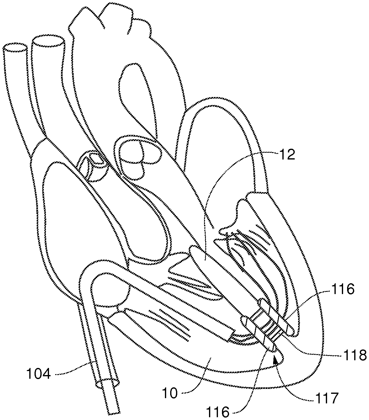
FIG. 1 is a view of a device for venous access into a heart chamber via the femoral vein to facilitate repair of a heart valve leaflet according to an embodiment of the present invention;
FIG. 2A is a view of a valve leaflet repair device according to an embodiment of the present invention with an internal guide and puncture tool passed into the left ventricle;
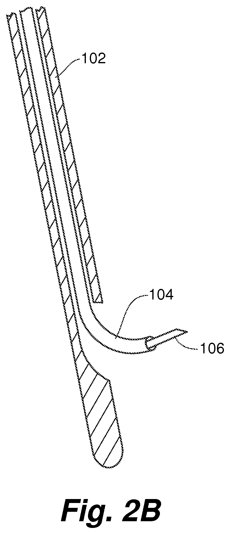
FIG. 2B is a partial view of the valve leaflet repair device depicted in FIG. 2A;
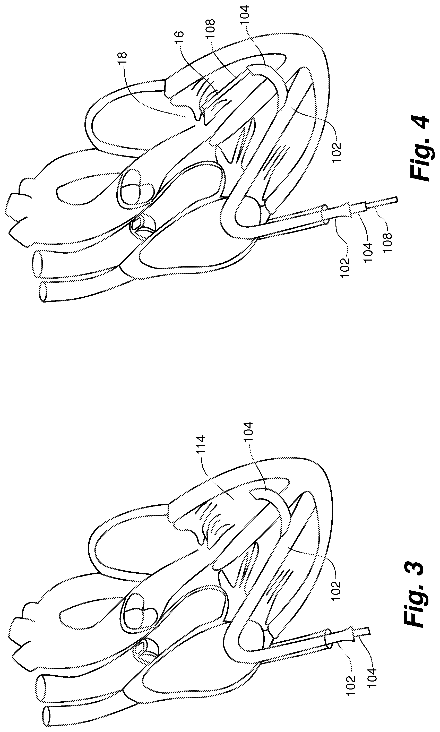
FIG. 3 is a view of a valve leaflet repair device according to an embodiment of the present invention with an internal guide exiting a side exit guide catheter;
FIG. 4 is a view of a valve leaflet repair device according to an embodiment of the present invention with a deployment catheter exiting an internal guide and positioned at the mitral valve;
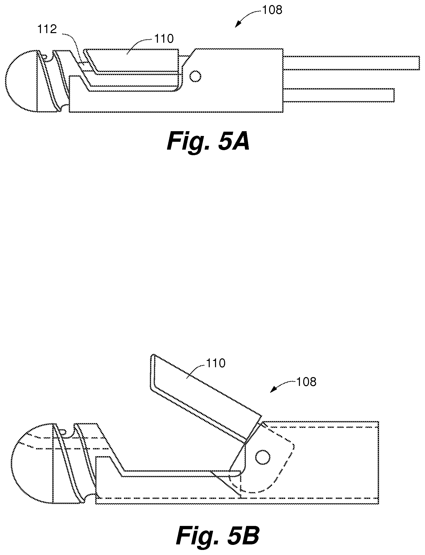
FIG. 5A is a view of a deployment catheter tip according to an embodiment of the present invention with a moveable catheter jaw and a suture capture needle, with the catheter jaw in the closed position;
FIG. 5B is a view of the deployment catheter tip of FIG. 5A with the moveable catheter in the open position;
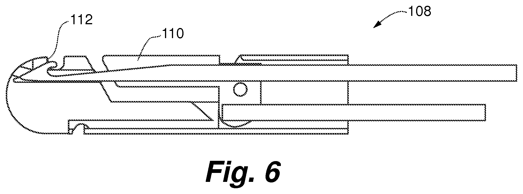
FIG. 6 is a cross-sectional view of the deployment catheter tip of FIGS. 5A and 5B;
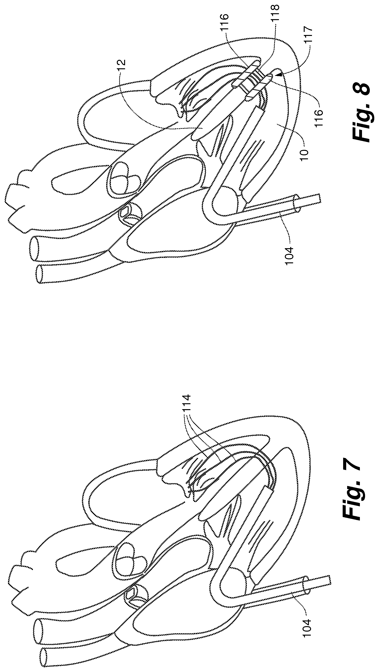
FIG. 7 is a view of a valve leaflet repair device according to an embodiment of the present invention with several sutures attached to the mitral valve and exiting through an internal guide;
FIG. 8 is a view of a valve leaflet repair device according to an embodiment of the present invention with ventricular septal seal devices deployed in the septal wall with sutures extending through a center lumen;
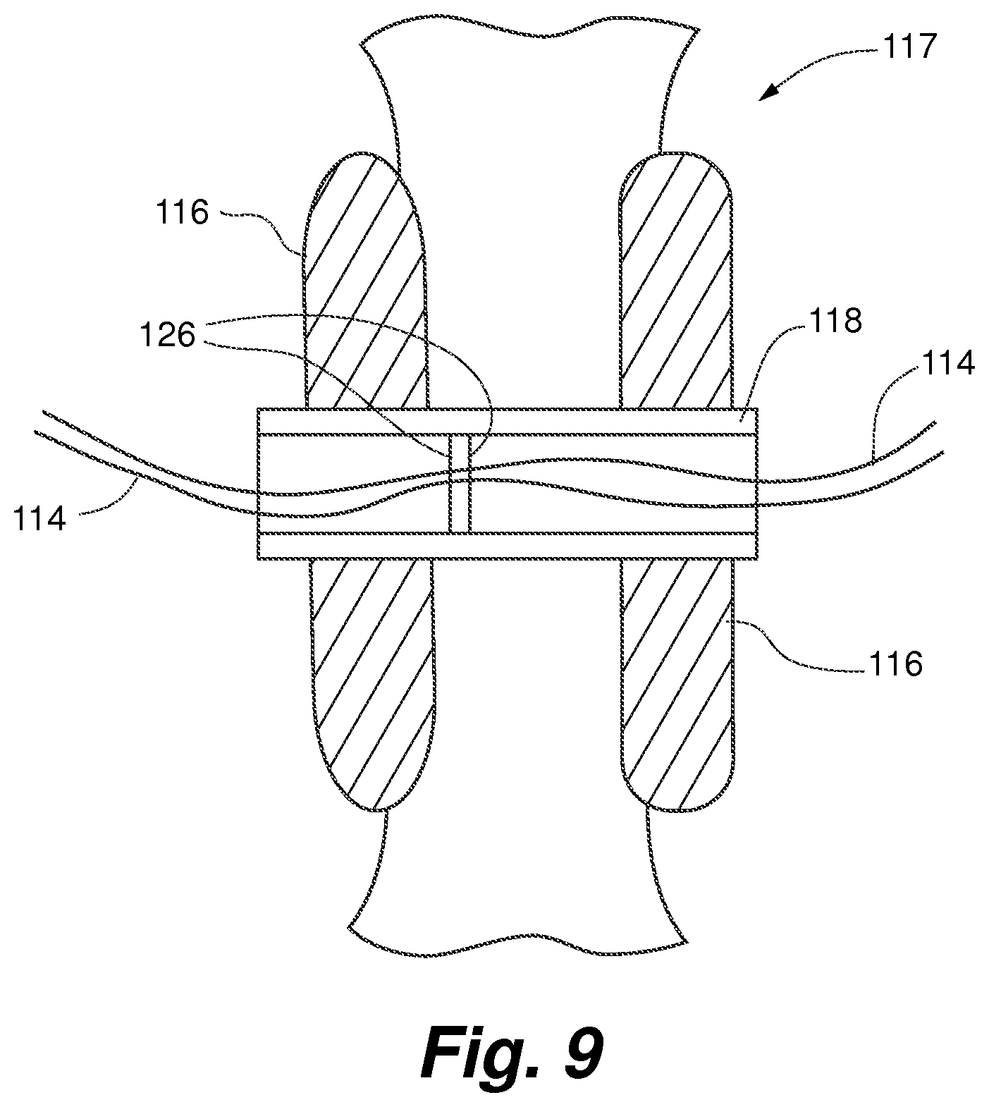
FIG. 9 is a schematic representation of the septal seal device of FIG. 8 in place in the heart;
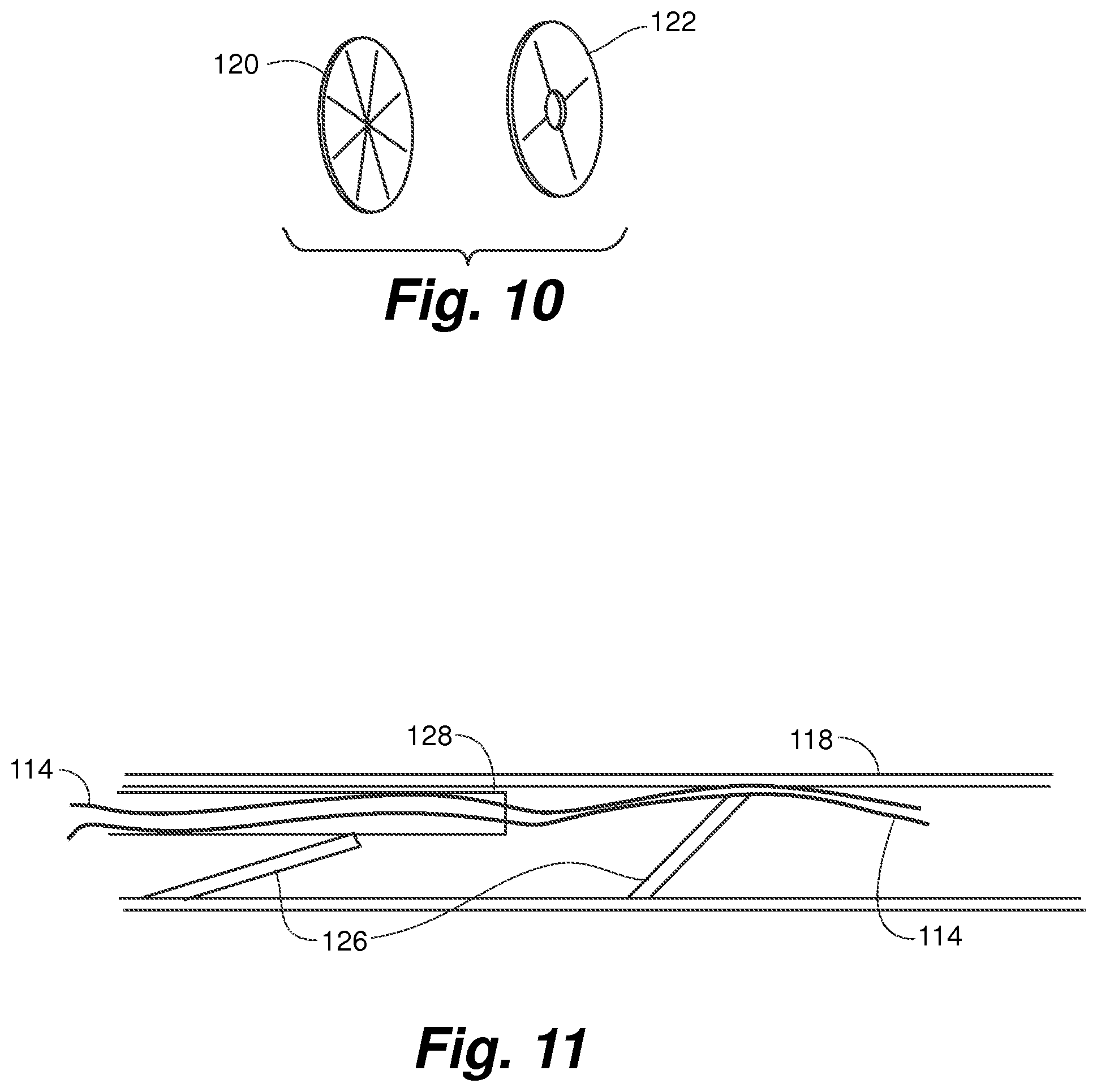
FIG. 10 is a perspective view of septal seal types according to embodiments of the present invention;
FIG. 11 is a partial view of a septal seal device lumen with a seal element for holding a suture in tension showing the suture freed from tension by a catheter that releases the seal element;
FIG. 12 is a view of a valve leaflet repair device according to an embodiment of the present invention with an anchor device fixing the position of the sutures;
FIG. 13 is a side cut-away view of the anchor device of FIG. 12 having a fixation catheter with a locking element for mating with seal internal lock features;
FIG. 14 is a view of a valve leaflet repair device according to an embodiment of the present invention with a cutting device for cutting sutures at the right ventricular side of a septal seal;
FIG. 15 is a side cross-sectional view of the suture cutting device of FIG. 14;
FIG. 16 is a view of a completed implant procedure using a valve leaflet repair device according to an embodiment of the present invention;
FIG. 17 is a flow chart of surgical procedural steps for repair of heart valve leaflets according to an embodiment of the present invention.
While the present invention is amenable to various modifications and alternative forms, specifics thereof have been shown by way of example in the drawings and will be described in detail. It should be understood, however, that the intention is not to limit the present invention to the particular embodiments described. On the contrary, the invention is to cover all modifications, equivalents, and alternatives falling within the spirit and scope of the present invention.
DESCRIPTION OF EMBODIMENTS
In the following detailed description of the present invention, numerous specific details are set forth in order to provide a thorough understanding of the present invention. However, one skilled in the art will recognize that various embodiments of the present invention may be practiced without these specific details. In other instances, well-known methods, procedures, and components have not been described in detail so as to not unnecessarily obscure aspects of the present invention.
One embodiment of the heart valve repair and delivery system will be examined to demonstrate the multiple catheter access steps required to enter the target heart chamber and deliver the repair device. This embodiment performs the repair of mitral valve regurgitation by delivering sutures to repair the defective valve with a deployment catheter that acts to reduce/eliminate mitral valve regurgitation (MR). In other embodiments, the access approach described herein can be used to access the heart for any other type of procedure, such as, for example, a heart valve replacement, repair of another heart structure or delivery of repair devices other than sutures to valve leaflets.
Embodiments of the present invention can be used as a vascular access system. It can include a standard vascular introducer that 1) eliminates the need for multiple passes of the instrument against the vein wall, 2) minimizes blood loss due to instrument leakage (circular components are more amenable to closer tolerances and sealing capability), and 3) reduces push/pull forces on the vein wall. The introducer contains seals to maintain hemostasis during instrument exchanges. A side exiting external guide catheter 102 can provide access into the right ventricle 10 as shown in FIG. 1. In one embodiment, a distal end of the external guide 102 can include a suction element to ensure that it holds its position in the right ventricle at, for example, the right ventricular apex. The system can include an internal guide catheter 104 disposed in the side exiting external guide catheter 102 design that facilitates the access through the right ventricle 10 to the right ventricular wall. The introducer and/or external guide catheter 102 can therefore function as means for accessing the right ventricle. A standard septal puncture tool 106 with a needle like end can serve as a means for creating an opening in the septum to create the hole in the ventricular septal wall 12 to provide the passageway for the guide catheter 104 through the wall as depicted in FIG. 2A. As used herein, the term catheter can refer to an elongate, generally flexible and tubular medical device that extends along a longitudinal axis and defines a diameter around the longitudinal axis.
The pre-shaped internal guide catheter 104 is then advanced into the left ventricle 14, as shown in FIG. 3, and positioned to deliver a deployment catheter 108 to properly capture a leaflet 16 of the mitral valve 18 for repair as shown in FIG. 4. The internal guide catheter 104 can therefore function as a means for positioning the deployment catheter 108 in the left ventricle. The deployment catheter 108, as shown in FIGS. 5A-5B and 6, can provide a means for deploying a repair device and can include a clamping mechanism 110 or other means for grasping for capturing the leaflet and a suture deployment mechanism including a suture capture needle 112 or other means for inserting the suture into the leaflet. The deployment catheter 108 can be exchangeable within the guide catheter 104 to permit multiple suture 114 deployments on the valve leaflet as shown in FIG. 7. Alternatively, the deployment catheter 108 can deliver several sutures 114 at one deployment. Note that in some Figures, such as FIG. 7, the external guide catheter 102 is not shown for sake of clarity.
As can be seen in FIG. 4, embodiments of the present invention provide a tri-catheter approach for accessing a heart valve to deploy a repair device onto a portion of the valve, such as a valve leaflet. The tri-catheter approach can include the external guide catheter 102, internal guide catheter 104 received within the external guide catheter 102 and deployment catheter 108 received within the internal guide catheter 104. In some embodiments, as depicted in FIG. 4, the tri-catheter arrangement can define a generally S-shaped access configuration to the valve with the catheters defining a first curv
D00000
D00001
D00002
D00003
D00004
D00005
D00006
D00007
D00008
D00009
D00010
D00011
D00012
XML
uspto.report is an independent third-party trademark research tool that is not affiliated, endorsed, or sponsored by the United States Patent and Trademark Office (USPTO) or any other governmental organization. The information provided by uspto.report is based on publicly available data at the time of writing and is intended for informational purposes only.
While we strive to provide accurate and up-to-date information, we do not guarantee the accuracy, completeness, reliability, or suitability of the information displayed on this site. The use of this site is at your own risk. Any reliance you place on such information is therefore strictly at your own risk.
All official trademark data, including owner information, should be verified by visiting the official USPTO website at www.uspto.gov. This site is not intended to replace professional legal advice and should not be used as a substitute for consulting with a legal professional who is knowledgeable about trademark law.