Gyroscopically stabilized vehicle system
Houle
U.S. patent number 10,654,697 [Application Number 15/829,013] was granted by the patent office on 2020-05-19 for gyroscopically stabilized vehicle system. This patent grant is currently assigned to Hand Held Products, Inc.. The grantee listed for this patent is Hand Held Products, Inc.. Invention is credited to Scott Xavier Houle.


| United States Patent | 10,654,697 |
| Houle | May 19, 2020 |
Gyroscopically stabilized vehicle system
Abstract
A method of self-stabilizing a forklift having a volume dimensioning device, a weight sensor, and a gyroscopic disc when the forklift is lifting an object, comprises: determining dimensions and volume of the object with the volume dimensioning device; determining a weight of the object with the weight sensor; calculating an approximate center of gravity of the object; and stabilizing the forklift when lifting the object by rotating the gyroscopic disc at a rotational speed based on the determined weight and calculated approximate center of gravity of the object.
| Inventors: | Houle; Scott Xavier (Edmonds, WA) | ||||||||||
|---|---|---|---|---|---|---|---|---|---|---|---|
| Applicant: |
|
||||||||||
| Assignee: | Hand Held Products, Inc. (Fort
Mill, SC) |
||||||||||
| Family ID: | 66658855 | ||||||||||
| Appl. No.: | 15/829,013 | ||||||||||
| Filed: | December 1, 2017 |
Prior Publication Data
| Document Identifier | Publication Date | |
|---|---|---|
| US 20190169008 A1 | Jun 6, 2019 | |
| Current U.S. Class: | 1/1 |
| Current CPC Class: | B66F 9/07559 (20130101); B66F 17/003 (20130101); B66F 9/0755 (20130101) |
| Current International Class: | B66F 9/075 (20060101); B66F 17/00 (20060101) |
References Cited [Referenced By]
U.S. Patent Documents
| 5603239 | February 1997 | Chong |
| 6832725 | December 2004 | Gardiner et al. |
| 6983883 | January 2006 | Ridling |
| 7128266 | October 2006 | Zhu et al. |
| 7159783 | January 2007 | Walczyk et al. |
| 7413127 | August 2008 | Ehrhart et al. |
| 7472832 | January 2009 | Lombardi, II |
| 7726575 | June 2010 | Wang et al. |
| 8294969 | October 2012 | Plesko |
| 8317105 | November 2012 | Kotlarsky et al. |
| 8322622 | December 2012 | Liu |
| 8366005 | February 2013 | Kotlarsky et al. |
| 8371507 | February 2013 | Haggerty et al. |
| 8376233 | February 2013 | Van Horn et al. |
| 8381979 | February 2013 | Franz |
| 8390909 | March 2013 | Plesko |
| 8408464 | April 2013 | Zhu et al. |
| 8408468 | April 2013 | Horn et al. |
| 8408469 | April 2013 | Good |
| 8424768 | April 2013 | Rueblinger et al. |
| 8448863 | May 2013 | Xian et al. |
| 8457013 | June 2013 | Essinger et al. |
| 8459557 | June 2013 | Havens et al. |
| 8469272 | June 2013 | Kearney |
| 8474712 | July 2013 | Kearney et al. |
| 8479992 | July 2013 | Kotlarsky et al. |
| 8490877 | July 2013 | Kearney |
| 8517271 | August 2013 | Kotlarsky et al. |
| 8523076 | September 2013 | Good |
| 8528818 | September 2013 | Ehrhart et al. |
| 8544737 | October 2013 | Gomez et al. |
| 8548420 | October 2013 | Grunow et al. |
| 8550335 | October 2013 | Samek et al. |
| 8550354 | October 2013 | Gannon et al. |
| 8550357 | October 2013 | Kearney |
| 8556174 | October 2013 | Kosecki et al. |
| 8556176 | October 2013 | Van Horn et al. |
| 8556177 | October 2013 | Hussey et al. |
| 8559767 | October 2013 | Barber et al. |
| 8561895 | October 2013 | Gomez et al. |
| 8561903 | October 2013 | Sauerwein |
| 8561905 | October 2013 | Edmonds et al. |
| 8565107 | October 2013 | Pease et al. |
| 8571307 | October 2013 | Li et al. |
| 8579200 | November 2013 | Samek et al. |
| 8583924 | November 2013 | Caballero et al. |
| 8584945 | November 2013 | Wang et al. |
| 8587595 | November 2013 | Wang |
| 8587697 | November 2013 | Hussey et al. |
| 8588869 | November 2013 | Sauerwein et al. |
| 8590789 | November 2013 | Nahill et al. |
| 8596539 | December 2013 | Havens et al. |
| 8596542 | December 2013 | Havens et al. |
| 8596543 | December 2013 | Havens et al. |
| 8599271 | December 2013 | Havens et al. |
| 8599957 | December 2013 | Peake et al. |
| 8600158 | December 2013 | Li et al. |
| 8600167 | December 2013 | Showering |
| 8602309 | December 2013 | Longacre et al. |
| 8608053 | December 2013 | Meier et al. |
| 8608071 | December 2013 | Liu et al. |
| 8611309 | December 2013 | Wang et al. |
| 8615487 | December 2013 | Gomez et al. |
| 8621123 | December 2013 | Caballero |
| 8622303 | January 2014 | Meier et al. |
| 8628013 | January 2014 | Ding |
| 8628015 | January 2014 | Wang et al. |
| 8628016 | January 2014 | Winegar |
| 8629926 | January 2014 | Wang |
| 8630491 | January 2014 | Longacre et al. |
| 8635309 | January 2014 | Berthiaume et al. |
| 8636200 | January 2014 | Kearney |
| 8636212 | January 2014 | Nahill et al. |
| 8636215 | January 2014 | Ding et al. |
| 8636224 | January 2014 | Wang |
| 8638806 | January 2014 | Wang et al. |
| 8640958 | February 2014 | Lu et al. |
| 8640960 | February 2014 | Wang et al. |
| 8643717 | February 2014 | Li et al. |
| 8646692 | February 2014 | Meier et al. |
| 8646694 | February 2014 | Wang et al. |
| 8657200 | February 2014 | Ren et al. |
| 8659397 | February 2014 | Vargo et al. |
| 8668149 | March 2014 | Good |
| 8678285 | March 2014 | Kearney |
| 8678286 | March 2014 | Smith et al. |
| 8682077 | March 2014 | Longacre |
| D702237 | April 2014 | Oberpriller et al. |
| 8687282 | April 2014 | Feng et al. |
| 8692927 | April 2014 | Pease et al. |
| 8695880 | April 2014 | Bremer et al. |
| 8698949 | April 2014 | Grunow et al. |
| 8702000 | April 2014 | Barber et al. |
| 8717494 | May 2014 | Gannon |
| 8720783 | May 2014 | Biss et al. |
| 8723804 | May 2014 | Fletcher et al. |
| 8723904 | May 2014 | Marty et al. |
| 8727223 | May 2014 | Wang |
| 8740082 | June 2014 | Wilz |
| 8740085 | June 2014 | Furlong et al. |
| 8746563 | June 2014 | Hennick et al. |
| 8750445 | June 2014 | Peake et al. |
| 8752766 | June 2014 | Xian et al. |
| 8756059 | June 2014 | Braho et al. |
| 8757495 | June 2014 | Qu et al. |
| 8760563 | June 2014 | Koziol et al. |
| 8763909 | July 2014 | Reed et al. |
| 8777108 | July 2014 | Coyle |
| 8777109 | July 2014 | Oberpriller et al. |
| 8779898 | July 2014 | Havens et al. |
| 8781520 | July 2014 | Payne et al. |
| 8783573 | July 2014 | Havens et al. |
| 8789757 | July 2014 | Barten |
| 8789758 | July 2014 | Hawley et al. |
| 8789759 | July 2014 | Xian et al. |
| 8794520 | August 2014 | Wang et al. |
| 8794522 | August 2014 | Ehrhart |
| 8794525 | August 2014 | Amundsen et al. |
| 8794526 | August 2014 | Wang et al. |
| 8798367 | August 2014 | Ellis |
| 8807431 | August 2014 | Wang et al. |
| 8807432 | August 2014 | Van Horn et al. |
| 8820630 | September 2014 | Qu et al. |
| 8822848 | September 2014 | Meagher |
| 8824692 | September 2014 | Sheerin et al. |
| 8824696 | September 2014 | Braho |
| 8842849 | September 2014 | Wahl et al. |
| 8844822 | September 2014 | Kotlarsky et al. |
| 8844823 | September 2014 | Fritz et al. |
| 8849019 | September 2014 | Li et al. |
| D716285 | October 2014 | Chaney et al. |
| 8851383 | October 2014 | Yeakley et al. |
| 8854633 | October 2014 | Laffargue |
| 8866963 | October 2014 | Grunow et al. |
| 8868421 | October 2014 | Braho et al. |
| 8868519 | October 2014 | Maloy et al. |
| 8868802 | October 2014 | Barten |
| 8868803 | October 2014 | Caballero |
| 8870074 | October 2014 | Gannon |
| 8879639 | November 2014 | Sauerwein |
| 8880426 | November 2014 | Smith |
| 8881983 | November 2014 | Havens et al. |
| 8881987 | November 2014 | Wang |
| 8903172 | December 2014 | Smith |
| 8908995 | December 2014 | Benos et al. |
| 8910870 | December 2014 | Li et al. |
| 8910875 | December 2014 | Ren et al. |
| 8914290 | December 2014 | Hendrickson et al. |
| 8914788 | December 2014 | Pettinelli et al. |
| 8915439 | December 2014 | Feng et al. |
| 8915444 | December 2014 | Havens et al. |
| 8916789 | December 2014 | Woodburn |
| 8918250 | December 2014 | Hollifield |
| 8918564 | December 2014 | Caballero |
| 8925818 | January 2015 | Kosecki et al. |
| 8939374 | January 2015 | Jovanovski et al. |
| 8942480 | January 2015 | Ellis |
| 8944313 | February 2015 | Williams et al. |
| 8944327 | February 2015 | Meier et al. |
| 8944332 | February 2015 | Harding et al. |
| 8950678 | February 2015 | Germaine et al. |
| D723560 | March 2015 | Zhou et al. |
| 8967468 | March 2015 | Gomez et al. |
| 8971346 | March 2015 | Sevier |
| 8976030 | March 2015 | Cunningham et al. |
| 8976368 | March 2015 | Akel et al. |
| 8978981 | March 2015 | Guan |
| 8978983 | March 2015 | Bremer et al. |
| 8978984 | March 2015 | Hennick et al. |
| 8985456 | March 2015 | Zhu et al. |
| 8985457 | March 2015 | Soule et al. |
| 8985459 | March 2015 | Kearney et al. |
| 8985461 | March 2015 | Gelay et al. |
| 8988578 | March 2015 | Showering |
| 8988590 | March 2015 | Gillet et al. |
| 8991704 | March 2015 | Hopper et al. |
| 8996194 | March 2015 | Davis et al. |
| 8996384 | March 2015 | Funyak et al. |
| 8998091 | April 2015 | Edmonds et al. |
| 9002641 | April 2015 | Showering |
| 9007368 | April 2015 | Laffargue et al. |
| 9010641 | April 2015 | Qu et al. |
| 9015513 | April 2015 | Murawski et al. |
| 9016576 | April 2015 | Brady et al. |
| D730357 | May 2015 | Fitch et al. |
| 9022288 | May 2015 | Nahill et al. |
| 9030964 | May 2015 | Essinger et al. |
| 9033240 | May 2015 | Smith et al. |
| 9033242 | May 2015 | Gillet et al. |
| 9036054 | May 2015 | Koziol et al. |
| 9037344 | May 2015 | Chamberlin |
| 9038911 | May 2015 | Xian et al. |
| 9038915 | May 2015 | Smith |
| D730901 | June 2015 | Oberpriller et al. |
| D730902 | June 2015 | Fitch et al. |
| 9047098 | June 2015 | Barten |
| 9047359 | June 2015 | Caballero et al. |
| 9047420 | June 2015 | Caballero |
| 9047525 | June 2015 | Barber |
| 9047531 | June 2015 | Showering et al. |
| 9049640 | June 2015 | Wang et al. |
| 9053055 | June 2015 | Caballero |
| 9053378 | June 2015 | Hou et al. |
| 9053380 | June 2015 | Xian et al. |
| 9057641 | June 2015 | Amundsen et al. |
| 9058526 | June 2015 | Powilleit |
| 9061527 | June 2015 | Tobin et al. |
| 9064165 | June 2015 | Havens et al. |
| 9064167 | June 2015 | Xian et al. |
| 9064168 | June 2015 | Todeschini et al. |
| 9064254 | June 2015 | Todeschini et al. |
| 9066032 | June 2015 | Wang |
| 9070032 | June 2015 | Corcoran |
| D734339 | July 2015 | Zhou et al. |
| D734751 | July 2015 | Oberpriller et al. |
| 9076459 | July 2015 | Braho et al. |
| 9079423 | July 2015 | Bouverie et al. |
| 9080856 | July 2015 | Laffargue |
| 9082023 | July 2015 | Feng et al. |
| 9084032 | July 2015 | Rautiola et al. |
| 9087250 | July 2015 | Coyle |
| 9092681 | July 2015 | Havens et al. |
| 9092682 | July 2015 | Wilz et al. |
| 9092683 | July 2015 | Koziol et al. |
| 9093141 | July 2015 | Liu |
| D737321 | August 2015 | Lee |
| 9098763 | August 2015 | Lu et al. |
| 9104929 | August 2015 | Todeschini |
| 9104934 | August 2015 | Li et al. |
| 9107484 | August 2015 | Chaney |
| 9111159 | August 2015 | Liu et al. |
| 9111166 | August 2015 | Cunningham |
| 9135483 | September 2015 | Liu et al. |
| 9137009 | September 2015 | Gardiner |
| 9141839 | September 2015 | Xian et al. |
| 9147096 | September 2015 | Wang |
| 9148474 | September 2015 | Skvoretz |
| 9158000 | October 2015 | Sauerwein |
| 9158340 | October 2015 | Reed et al. |
| 9158953 | October 2015 | Gillet et al. |
| 9159059 | October 2015 | Daddabbo et al. |
| 9165174 | October 2015 | Huck |
| 9171543 | October 2015 | Emerick et al. |
| 9183425 | November 2015 | Wang |
| 9189669 | November 2015 | Zhu et al. |
| 9195844 | November 2015 | Todeschini et al. |
| 9202458 | December 2015 | Braho et al. |
| 9208366 | December 2015 | Liu |
| 9208367 | December 2015 | Wang |
| 9219836 | December 2015 | Bouverie et al. |
| 9224022 | December 2015 | Ackley et al. |
| 9224024 | December 2015 | Bremer et al. |
| 9224027 | December 2015 | Van Horn et al. |
| D747321 | January 2016 | London et al. |
| 9230140 | January 2016 | Ackley |
| 9235553 | January 2016 | Fitch et al. |
| 9239950 | January 2016 | Fletcher |
| 9245492 | January 2016 | Ackley et al. |
| 9443123 | January 2016 | Hejl |
| 9248640 | February 2016 | Heng |
| 9250652 | February 2016 | London et al. |
| 9250712 | February 2016 | Todeschini |
| 9251411 | February 2016 | Todeschini |
| 9258033 | February 2016 | Showering |
| 9262633 | February 2016 | Todeschini et al. |
| 9262660 | February 2016 | Lu et al. |
| 9262662 | February 2016 | Chen et al. |
| 9269036 | February 2016 | Bremer |
| 9270782 | February 2016 | Hala et al. |
| 9274812 | March 2016 | Doren et al. |
| 9275388 | March 2016 | Havens et al. |
| 9277668 | March 2016 | Feng et al. |
| 9280693 | March 2016 | Feng et al. |
| 9286496 | March 2016 | Smith |
| 9297900 | March 2016 | Jiang |
| 9298964 | March 2016 | Li et al. |
| 9301427 | March 2016 | Feng et al. |
| D754205 | April 2016 | Nguyen et al. |
| D754206 | April 2016 | Nguyen et al. |
| 9304376 | April 2016 | Anderson |
| 9310609 | April 2016 | Rueblinger et al. |
| 9313377 | April 2016 | Todeschini et al. |
| 9317037 | April 2016 | Byford et al. |
| 9319548 | April 2016 | Showering et al. |
| D757009 | May 2016 | Oberpriller et al. |
| 9342723 | May 2016 | Liu et al. |
| 9342724 | May 2016 | McCloskey |
| 9361882 | June 2016 | Ressler et al. |
| 9365381 | June 2016 | Colonel et al. |
| 9373018 | June 2016 | Colavito et al. |
| 9375945 | June 2016 | Bowles |
| 9378403 | June 2016 | Wang et al. |
| D760719 | July 2016 | Zhou et al. |
| 9360304 | July 2016 | Chang et al. |
| 9383848 | July 2016 | Daghigh |
| 9384374 | July 2016 | Bianconi |
| 9390304 | July 2016 | Chang et al. |
| 9390596 | July 2016 | Todeschini |
| D762604 | August 2016 | Fitch et al. |
| 9411386 | August 2016 | Sauerwein |
| 9412242 | August 2016 | Van Horn et al. |
| 9418269 | August 2016 | Havens et al. |
| 9418270 | August 2016 | Van Volkinburg et al. |
| 9423318 | August 2016 | Lui et al. |
| D766244 | September 2016 | Zhou et al. |
| 9443222 | September 2016 | Singel et al. |
| 9454689 | September 2016 | McCloskey et al. |
| 9464885 | October 2016 | Lloyd et al. |
| 9465967 | October 2016 | Xian et al. |
| 9478113 | October 2016 | Xie et al. |
| 9478983 | October 2016 | Kather et al. |
| D771631 | November 2016 | Fitch et al. |
| 9481186 | November 2016 | Bouverie et al. |
| 9487113 | November 2016 | Schukalski |
| 9488986 | November 2016 | Solanki |
| 9489782 | November 2016 | Payne et al. |
| 9490540 | November 2016 | Davies et al. |
| 9491729 | November 2016 | Rautiola et al. |
| 9497092 | November 2016 | Gomez et al. |
| 9507974 | November 2016 | Todeschini |
| 9519814 | December 2016 | Cudzilo |
| 9521331 | December 2016 | Bessettes et al. |
| 9530038 | December 2016 | Xian et al. |
| D777166 | January 2017 | Bidwell et al. |
| 9558386 | January 2017 | Yeakley |
| 9572901 | February 2017 | Todeschini |
| 9606581 | March 2017 | Howe et al. |
| D783601 | April 2017 | Schulte et al. |
| D785617 | May 2017 | Bidwell et al. |
| D785636 | May 2017 | Oberpriller et al. |
| 9646189 | May 2017 | Lu et al. |
| 9646191 | May 2017 | Unemyr et al. |
| 9652648 | May 2017 | Ackley et al. |
| 9652653 | May 2017 | Todeschini et al. |
| 9656487 | May 2017 | Ho et al. |
| 9659198 | May 2017 | Giordano et al. |
| D790505 | June 2017 | Vargo et al. |
| D790546 | June 2017 | Zhou et al. |
| 9680282 | June 2017 | Hanenburg |
| 9697401 | July 2017 | Feng et al. |
| 9701140 | July 2017 | Alaganchetty et al. |
| 2007/0063048 | March 2007 | Havens et al. |
| 2009/0134221 | May 2009 | Zhu et al. |
| 2010/0177076 | July 2010 | Essinger et al. |
| 2010/0177080 | July 2010 | Essinger et al. |
| 2010/0177707 | July 2010 | Essinger et al. |
| 2010/0177749 | July 2010 | Essinger et al. |
| 2011/0169999 | July 2011 | Grunow et al. |
| 2011/0202554 | August 2011 | Powilleit et al. |
| 2012/0101684 | April 2012 | Takazato |
| 2012/0111946 | May 2012 | Golant |
| 2012/0168512 | July 2012 | Kotlarsky et al. |
| 2012/0193423 | August 2012 | Samek |
| 2012/0194692 | August 2012 | Mers et al. |
| 2012/0203647 | August 2012 | Smith |
| 2012/0223141 | September 2012 | Good et al. |
| 2013/0043312 | February 2013 | Van Horn |
| 2013/0075168 | March 2013 | Amundsen et al. |
| 2013/0124430 | June 2013 | Moir et al. |
| 2013/0175341 | July 2013 | Kearney et al. |
| 2013/0175343 | July 2013 | Good |
| 2013/0257744 | October 2013 | Daghigh et al. |
| 2013/0257759 | October 2013 | Daghigh |
| 2013/0270346 | October 2013 | Xian et al. |
| 2013/0292475 | November 2013 | Kotlarsky et al. |
| 2013/0292477 | November 2013 | Hennick et al. |
| 2013/0293539 | November 2013 | Hunt et al. |
| 2013/0293540 | November 2013 | Laffargue et al. |
| 2013/0306728 | November 2013 | Thuries et al. |
| 2013/0306731 | November 2013 | Pedraro |
| 2013/0307964 | November 2013 | Bremer et al. |
| 2013/0308625 | November 2013 | Park et al. |
| 2013/0313324 | November 2013 | Koziol et al. |
| 2013/0332524 | December 2013 | Fiala et al. |
| 2013/0332996 | December 2013 | Fiala et al. |
| 2014/0001267 | January 2014 | Giordano et al. |
| 2014/0002828 | January 2014 | Laffargue et al. |
| 2014/0025584 | January 2014 | Liu et al. |
| 2014/0100813 | January 2014 | Showering |
| 2014/0034734 | February 2014 | Sauerwein |
| 2014/0036848 | February 2014 | Pease et al. |
| 2014/0039693 | February 2014 | Havens et al. |
| 2014/0049120 | February 2014 | Kohtz et al. |
| 2014/0049635 | February 2014 | Laffargue et al. |
| 2014/0061306 | March 2014 | Wu et al. |
| 2014/0063289 | March 2014 | Hussey et al. |
| 2014/0066136 | March 2014 | Sauerwein et al. |
| 2014/0067692 | March 2014 | Ye et al. |
| 2014/0070005 | March 2014 | Nahill et al. |
| 2014/0071840 | March 2014 | Venancio |
| 2014/0074746 | March 2014 | Wang |
| 2014/0076974 | March 2014 | Havens et al. |
| 2014/0078342 | March 2014 | Li et al. |
| 2014/0098792 | April 2014 | Wang et al. |
| 2014/0100774 | April 2014 | Showering |
| 2014/0103115 | April 2014 | Meier et al. |
| 2014/0104413 | April 2014 | McCloskey et al. |
| 2014/0104414 | April 2014 | McCloskey et al. |
| 2014/0104416 | April 2014 | Giordano et al. |
| 2014/0106725 | April 2014 | Sauerwein |
| 2014/0108010 | April 2014 | Maltseff et al. |
| 2014/0108402 | April 2014 | Gomez et al. |
| 2014/0108682 | April 2014 | Caballero |
| 2014/0110485 | April 2014 | Toa et al. |
| 2014/0114530 | April 2014 | Fitch et al. |
| 2014/0125853 | May 2014 | Wang |
| 2014/0125999 | May 2014 | Longacre et al. |
| 2014/0129378 | May 2014 | Richardson |
| 2014/0131443 | May 2014 | Smith |
| 2014/0131444 | May 2014 | Wang |
| 2014/0133379 | May 2014 | Wang et al. |
| 2014/0136208 | May 2014 | Maltseff et al. |
| 2014/0140585 | May 2014 | Wang |
| 2014/0152882 | June 2014 | Samek et al. |
| 2014/0158770 | June 2014 | Sevier et al. |
| 2014/0159869 | June 2014 | Zumsteg et al. |
| 2014/0166755 | June 2014 | Liu et al. |
| 2014/0166757 | June 2014 | Smith |
| 2014/0166759 | June 2014 | Liu et al. |
| 2014/0168787 | June 2014 | Wang et al. |
| 2014/0175165 | June 2014 | Havens et al. |
| 2014/0191684 | July 2014 | Valois |
| 2014/0191913 | July 2014 | Ge et al. |
| 2014/0197239 | July 2014 | Havens et al. |
| 2014/0197304 | July 2014 | Feng et al. |
| 2014/0204268 | July 2014 | Grunow et al. |
| 2014/0214631 | July 2014 | Hansen |
| 2014/0217166 | August 2014 | Berthiaume et al. |
| 2014/0217180 | August 2014 | Liu |
| 2014/0231500 | August 2014 | Ehrhart et al. |
| 2014/0247315 | September 2014 | Marty et al. |
| 2014/0263493 | September 2014 | Amurgis et al. |
| 2014/0263645 | September 2014 | Smith et al. |
| 2014/0270196 | September 2014 | Braho et al. |
| 2014/0270229 | September 2014 | Braho |
| 2014/0278387 | September 2014 | DiGregorio |
| 2014/0282210 | September 2014 | Bianconi |
| 2014/0288933 | September 2014 | Braho et al. |
| 2014/0297058 | October 2014 | Barker et al. |
| 2014/0299665 | October 2014 | Barber et al. |
| 2014/0332590 | November 2014 | Wang et al. |
| 2014/0351317 | November 2014 | Smith et al. |
| 2014/0362184 | December 2014 | Jovanovski et al. |
| 2014/0363015 | December 2014 | Braho |
| 2014/0369511 | December 2014 | Sheerin et al. |
| 2014/0374483 | December 2014 | Lu |
| 2014/0374485 | December 2014 | Xian et al. |
| 2015/0001301 | January 2015 | Ouyang |
| 2015/0009338 | January 2015 | Laffargue et al. |
| 2015/0014416 | January 2015 | Kotlarsky et al. |
| 2015/0021397 | January 2015 | Rueblinger et al. |
| 2015/0028104 | January 2015 | Ma et al. |
| 2015/0029002 | January 2015 | Yeakley et al. |
| 2015/0032709 | January 2015 | Maloy et al. |
| 2015/0039309 | February 2015 | Braho et al. |
| 2015/0040378 | February 2015 | Saber et al. |
| 2015/0049347 | February 2015 | Laffargue et al. |
| 2015/0051992 | February 2015 | Smith |
| 2015/0053769 | February 2015 | Thuries et al. |
| 2015/0062366 | March 2015 | Liu et al. |
| 2015/0063215 | March 2015 | Wang |
| 2015/0088522 | March 2015 | Hendrickson et al. |
| 2015/0096872 | April 2015 | Woodburn |
| 2015/0100196 | April 2015 | Hollifield |
| 2015/0115035 | April 2015 | Meier et al. |
| 2015/0127791 | May 2015 | Kosecki et al. |
| 2015/0128116 | May 2015 | Chen et al. |
| 2015/0133047 | May 2015 | Smith et al. |
| 2015/0134470 | May 2015 | Hejl et al. |
| 2015/0136851 | May 2015 | Harding et al. |
| 2015/0142492 | May 2015 | Kumar |
| 2015/0144692 | May 2015 | Hejl |
| 2015/0144698 | May 2015 | Teng et al. |
| 2015/0149946 | May 2015 | Benos et al. |
| 2015/0161429 | June 2015 | Xian |
| 2015/0178523 | June 2015 | Gelay et al. |
| 2015/0178537 | June 2015 | El et al. |
| 2015/0178685 | June 2015 | Krumel et al. |
| 2015/0181109 | June 2015 | Gillet et al. |
| 2015/0186703 | July 2015 | Chen et al. |
| 2015/0199957 | July 2015 | Funyak et al. |
| 2015/0210199 | July 2015 | Payne |
| 2015/0212565 | July 2015 | Murawski et al. |
| 2015/0213647 | July 2015 | Laffargue et al. |
| 2015/0220753 | August 2015 | Zhu et al. |
| 2015/0220901 | August 2015 | Gomez et al. |
| 2015/0227189 | August 2015 | Davis et al. |
| 2015/0236984 | August 2015 | Sevier |
| 2015/0239348 | August 2015 | Chamberlin |
| 2015/0242658 | August 2015 | Nahill et al. |
| 2015/0248572 | September 2015 | Soule et al. |
| 2015/0254485 | September 2015 | Feng et al. |
| 2015/0261643 | September 2015 | Caballero et al. |
| 2015/0264624 | September 2015 | Wang et al. |
| 2015/0268971 | September 2015 | Barten |
| 2015/0269402 | September 2015 | Barber et al. |
| 2015/0288689 | October 2015 | Todeschini et al. |
| 2015/0288896 | October 2015 | Wang |
| 2015/0310243 | October 2015 | Ackley |
| 2015/0310244 | October 2015 | Kian et al. |
| 2015/0310389 | October 2015 | Crimm et al. |
| 2015/0312780 | October 2015 | Wang et al. |
| 2015/0327012 | November 2015 | Bian et al. |
| 2016/0014251 | January 2016 | Hejl |
| 2016/0025697 | January 2016 | Alt et al. |
| 2016/0026838 | January 2016 | Gillet et al. |
| 2016/0026839 | January 2016 | Du et al. |
| 2016/0040982 | February 2016 | Li et al. |
| 2016/0042241 | February 2016 | Todeschini |
| 2016/0057230 | February 2016 | Todeschini et al. |
| 2016/0062473 | March 2016 | Bouchat et al. |
| 2016/0092805 | March 2016 | Geisler et al. |
| 2016/0101936 | April 2016 | Chamberlin |
| 2016/0102975 | April 2016 | McCloskey et al. |
| 2016/0104019 | April 2016 | Todeschini et al. |
| 2016/0104274 | April 2016 | Jovanovski et al. |
| 2016/0109219 | April 2016 | Ackley et al. |
| 2016/0109220 | April 2016 | Laffargue |
| 2016/0109224 | April 2016 | Thuries et al. |
| 2016/0112631 | April 2016 | Ackley et al. |
| 2016/0112643 | April 2016 | Laffargue et al. |
| 2016/0117627 | April 2016 | Raj et al. |
| 2016/0124516 | May 2016 | Schoon et al. |
| 2016/0125217 | May 2016 | Todeschini |
| 2016/0125342 | May 2016 | Miller et al. |
| 2016/0133253 | May 2016 | Braho et al. |
| 2016/0171597 | June 2016 | Todeschini |
| 2016/0171666 | June 2016 | McCloskey |
| 2016/0171720 | June 2016 | Todeschini |
| 2016/0171775 | June 2016 | Todeschini et al. |
| 2016/0171777 | June 2016 | Todeschini et al. |
| 2016/0174674 | June 2016 | Oberpriller et al. |
| 2016/0178479 | June 2016 | Goldsmith |
| 2016/0178685 | June 2016 | Young et al. |
| 2016/0178707 | June 2016 | Young et al. |
| 2016/0179132 | June 2016 | Harr et al. |
| 2016/0179143 | June 2016 | Bidwell et al. |
| 2016/0179368 | June 2016 | Roeder |
| 2016/0179378 | June 2016 | Kent et al. |
| 2016/0180130 | June 2016 | Bremer |
| 2016/0180133 | June 2016 | Oberpriller et al. |
| 2016/0180136 | June 2016 | Meier et al. |
| 2016/0180594 | June 2016 | Todeschini |
| 2016/0180663 | June 2016 | McMahan et al. |
| 2016/0180678 | June 2016 | Ackley et al. |
| 2016/0180713 | June 2016 | Bernhardt et al. |
| 2016/0185136 | June 2016 | Ng et al. |
| 2016/0185291 | June 2016 | Chamberlin |
| 2016/0186926 | June 2016 | Oberpriller et al. |
| 2016/0188861 | June 2016 | Todeschini |
| 2016/0188939 | June 2016 | Sailors et al. |
| 2016/0188940 | June 2016 | Lu et al. |
| 2016/0188941 | June 2016 | Todeschini et al. |
| 2016/0188942 | June 2016 | Good et al. |
| 2016/0188943 | June 2016 | Linwood |
| 2016/0188944 | June 2016 | Wilz et al. |
| 2016/0189076 | June 2016 | Mellott et al. |
| 2016/0189087 | June 2016 | Morton et al. |
| 2016/0189088 | June 2016 | Pecorari et al. |
| 2016/0189092 | June 2016 | George et al. |
| 2016/0189284 | June 2016 | Mellott et al. |
| 2016/0189288 | June 2016 | Todeschini |
| 2016/0189366 | June 2016 | Chamberlin et al. |
| 2016/0189443 | June 2016 | Smith |
| 2016/0189447 | June 2016 | Valenzuela |
| 2016/0189489 | June 2016 | Au et al. |
| 2016/0191684 | June 2016 | DiPiazza et al. |
| 2016/0192051 | June 2016 | DiPiazza et al. |
| 2016/0125873 | July 2016 | Braho et al. |
| 2016/0202951 | July 2016 | Pike et al. |
| 2016/0202958 | July 2016 | Zabel et al. |
| 2016/0202959 | July 2016 | Doubleday et al. |
| 2016/0203021 | July 2016 | Pike et al. |
| 2016/0203429 | July 2016 | Mellott et al. |
| 2016/0203797 | July 2016 | Pike et al. |
| 2016/0203820 | July 2016 | Zabel et al. |
| 2016/0204623 | July 2016 | Haggert et al. |
| 2016/0204636 | July 2016 | Allen et al. |
| 2016/0204638 | July 2016 | Miraglia et al. |
| 2016/0316190 | July 2016 | McCloskey et al. |
| 2016/0227912 | August 2016 | Oberpriller et al. |
| 2016/0232891 | August 2016 | Pecorari |
| 2016/0292477 | October 2016 | Bidwell |
| 2016/0294779 | October 2016 | Yeakley et al. |
| 2016/0306769 | October 2016 | Kohtz et al. |
| 2016/0314276 | October 2016 | Sewell et al. |
| 2016/0314294 | October 2016 | Kubler et al. |
| 2016/0323310 | November 2016 | Todeschini et al. |
| 2016/0325677 | November 2016 | Fitch et al. |
| 2016/0327614 | November 2016 | Young et al. |
| 2016/0327930 | November 2016 | Charpentier et al. |
| 2016/0328762 | November 2016 | Pape |
| 2016/0330218 | November 2016 | Hussey et al. |
| 2016/0343163 | November 2016 | Venkatesha et al. |
| 2016/0343176 | November 2016 | Ackley |
| 2016/0364914 | December 2016 | Todeschini |
| 2016/0370220 | December 2016 | Ackley et al. |
| 2016/0372282 | December 2016 | Bandringa |
| 2016/0373847 | December 2016 | Vargo et al. |
| 2016/0377414 | December 2016 | Thuries et al. |
| 2016/0377417 | December 2016 | Jovanovski et al. |
| 2017/0010141 | January 2017 | Ackley |
| 2017/0010328 | January 2017 | Mullen et al. |
| 2017/0010780 | January 2017 | Waldron et al. |
| 2017/0016714 | January 2017 | Laffargue et al. |
| 2017/0018094 | January 2017 | Todeschini |
| 2017/0046603 | February 2017 | Lee et al. |
| 2017/0047864 | February 2017 | Stang et al. |
| 2017/0053146 | February 2017 | Liu et al. |
| 2017/0053147 | February 2017 | Geramine et al. |
| 2017/0053647 | February 2017 | Nichols et al. |
| 2017/0055606 | March 2017 | Xu et al. |
| 2017/0060316 | March 2017 | Larson |
| 2017/0061961 | March 2017 | Nichols et al. |
| 2017/0064634 | March 2017 | Van Horn et al. |
| 2017/0083730 | March 2017 | Feng et al. |
| 2017/0091502 | March 2017 | Furlong et al. |
| 2017/0091706 | March 2017 | Lloyd et al. |
| 2017/0091741 | March 2017 | Todeschini |
| 2017/0091904 | March 2017 | Ventress |
| 2017/0092908 | March 2017 | Chaney |
| 2017/0094238 | March 2017 | Germaine et al. |
| 2017/0098947 | April 2017 | Wolski |
| 2017/0100949 | April 2017 | Celinder et al. |
| 2017/0108838 | April 2017 | Todeschinie et al. |
| 2017/0108895 | April 2017 | Chamberlin et al. |
| 2017/0118355 | April 2017 | Wong et al. |
| 2017/0123598 | May 2017 | Phan et al. |
| 2017/0124369 | May 2017 | Rueblinger et al. |
| 2017/0124396 | May 2017 | Todeschini et al. |
| 2017/0124687 | May 2017 | McCloskey et al. |
| 2017/0126873 | May 2017 | McGary et al. |
| 2017/0126904 | May 2017 | d'Armancourt et al. |
| 2017/0139012 | May 2017 | Smith |
| 2017/0140329 | May 2017 | Bernhardt et al. |
| 2017/0140731 | May 2017 | Smith |
| 2017/0147847 | May 2017 | Berggren et al. |
| 2017/0150124 | May 2017 | Thuries |
| 2017/0169198 | June 2017 | Nichols |
| 2017/0171035 | June 2017 | Lu et al. |
| 2017/0171703 | June 2017 | Maheswaranathan |
| 2017/0171803 | June 2017 | Maheswaranathan |
| 2017/0180359 | June 2017 | Wolski et al. |
| 2017/0180577 | June 2017 | Nguon et al. |
| 2017/0181299 | June 2017 | Shi et al. |
| 2017/0190192 | July 2017 | Delario et al. |
| 2017/0193432 | July 2017 | Bernhardt |
| 2017/0193461 | July 2017 | Jonas et al. |
| 2017/0193727 | July 2017 | Van Horn et al. |
| 2017/0199266 | July 2017 | Rice et al. |
| 2017/0200108 | July 2017 | Au et al. |
| 2017/0200275 | July 2017 | McCloskey et al. |
| 2017/0315014 | November 2017 | Regan |
| 2013163789 | Nov 2013 | WO | |||
Other References
|
Adaptalift Blog, "Forklift Terminology Part 3: Stability & Maneuverability", Dated Dec. 12, 2010, 3 pages. {Downloaded on Dec. 1, 2017 from http://www.aalhysterforklifts.com.au/index.php/about/blog-post/- forklift_terminology_part_3_stability_manoeuvrability}. cited by applicant. |
Primary Examiner: Zanelli; Michael J
Attorney, Agent or Firm: Alston & Bird LLP
Claims
What is claimed is:
1. A method to stabilize a forklift carrying a load, the method comprising: determining, by a volume dimensioning device, a dimension of the load and a volume of the load; determining, by a weight sensor, a weight of the load; calculating an approximate center of gravity of the load based on the determined dimension and volume of the load; and stabilizing the forklift when lifting the load by rotating the gyroscopic disc at a rotational speed determined based on the determined weight and calculated approximate center of gravity of the load.
2. The method of stabilizing the forklift of claim 1, wherein the volume dimensioning device is a 3D range camera.
3. The method of stabilizing the forklift of claim 1, wherein the weight sensor is a barcode reader operable to read a barcode positioned on the load, the barcode comprising information indicative of a weight of the load.
4. The method of stabilizing the forklift of claim 1, wherein the forklift comprises a plurality of gyroscopic discs.
5. The method of stabilizing the forklift of claim 4, the method further comprising: rotating two or more gyroscopic discs in response to the forklift lifting the load, wherein rotational speeds of the rotating gyroscopic discs are based on the approximate center of gravity and determined weight of the load.
6. The method of stabilizing the forklift of claim 5, wherein each gyroscopic disc of the two or more gyroscopic discs has a different diameter and weight than the other gyroscopic discs.
7. The method of stabilizing a forklift of claim 4, wherein when a total stabilizing force generated by rotating all the plurality of gyroscopic discs exceeds a stabilizing force needed to stabilize the forklift when lifting the load, a first gyroscopic disc is rotated, and a second gyroscopic disc remains stationary.
8. The method of stabilizing the forklift of claim 1, wherein the forklift further comprises a processor in communication with the volume dimensioning device and weight sensor, the processor being operable to: receive the determined volume and dimensions from the volume dimensioning device, and the determined weight from the weight sensor; perform the calculation of the approximate center of gravity of the object based on the calculated volume and dimensions and determined weight of the object; control a rotational speed of the gyroscopic disc; and responsive to the calculated approximate center of gravity and determined weight of the object, adjust the rotational speed of the gyroscopic disc.
9. The method of stabilizing the forklift of claim 1, wherein the volume dimensioning device is positioned on a mast of the forklift.
10. The method of stabilizing a forklift of claim 1, wherein the weight sensor is attached to a mast of the forklift and is configured to measure the weight of the object as the object is lifted by the forklift.
11. A method to stabilize a forklift, the method comprising: determining, by a weight sensor, a weight of an object; determining, by a volume dimensioning device, a dimension of the object and a volume of the object; calculating an approximate center of gravity of the object based on the determined dimensions and volume of the object; rotating a gyroscopic disc positioned in a disc receiving space of the forklift, at a rotational speed sufficient to stabilize the forklift when lifting the object, the rotational speed of the gyroscopic disc determined based on the calculated approximate center of gravity and the determined weight of the object.
12. The method of stabilizing a forklift of claim 11, wherein the volume dimensioning device is a 3D range camera.
13. The method of stabilizing a forklift of claim 11, wherein the volume dimensioning device is attached to a mast of the forklift.
14. The method of stabilizing a forklift of claim 11, wherein the weight sensor is attached to a mast of the forklift and is configured to measure the weight of the object as the object is lifted by the forklift.
15. The method of stabilizing a forklift of claim 11, wherein the forklift comprises a processor in communication with the volume dimensioning device and the weight sensor, the processor being configured to calculate the approximate center of gravity of the object.
16. The method of stabilizing a forklift of claim 15, wherein the processor is in communication with a motor controlling a rotational speed of the gyroscopic disc, and instructs the motor to adjust the rotational speed of the gyroscopic disc in response to the determined weight and calculated approximate center of gravity of the object.
17. The method of stabilizing a forklift of claim 11, wherein the forklift comprises a plurality of gyroscopic discs.
18. The method of stabilizing a forklift of claim 17, wherein each gyroscopic disc of the plurality of gyroscopic discs has a different diameter and weight than the other gyroscopic discs.
19. The method of stabilizing a forklift of claim 17, wherein in response to a total stabilizing force generated by rotating each gyroscopic disc of the plurality of gyroscopic discs exceeding a stabilizing force needed to stabilize the forklift when lifting the object, a first gyroscopic disc is rotated, and a second gyroscopic disc remains stationary.
20. The method of stabilizing a forklift of claim 11, wherein the weight sensor is a barcode reader operable to read a barcode positioned on an object to be lifted, the barcode comprising information indicative of a weight of the object.
Description
FIELD OF THE INVENTION
The invention is generally related to industrial vehicle stabilization systems, and, more specifically, to gyroscopically stabilized industrial vehicle systems.
BACKGROUND
Industrial vehicles, such as forklifts, are commonly used in warehouse and industrial settings to move and place objects. Often these objects are very heavy, necessitating conventional forklifts to be proportionally built to properly balance these heavy loads. As a general rule, the actual weight of a forklift (i.e. service weight) will be 1.5 to 2 times the lift capacity of the forklift. For example, if a forklift has a lifting capacity of 5,000 pounds, the service weight of the forklift will be somewhere between 7,500-10,000 pounds. This excessive weight helps the forklift, in combination with adjustable fulcrum points, to properly balance heavy loads without tipping over.
While the excessive weight helps properly balance heavy loads, the excessive weight comes at a cost of requiring large motors to operate the forklift. These large motors contribute to an increased service weight, and consume large quantities of energy to operate. Additionally, when lifting lighter loads, the forklift does not need all of the service weight in order to balance the load. However, the large motor will still consume large quantities of energy to move the unneeded weight.
If an industrial vehicle such as a forklift could be made lighter while maintaining the same lifting capacity as a conventional forklift, then the forklift could use a smaller motor, and the user could reduce operational costs.
SUMMARY
In an embodiment, a method of self-stabilizing a forklift having a volume dimensioning device, a weight sensor, and a gyroscopic disc when the forklift is lifting an object, comprises: determining dimensions and volume of the object with the volume dimensioning device; determining a weight of the object with the weight sensor; calculating an approximate center of gravity of the object; and stabilizing the forklift when lifting the object by rotating the gyroscopic disc at a rotational speed based on the determined weight and calculated approximate center of gravity of the object.
In an embodiment, the volume dimensioning device is a 3D range camera.
In an embodiment, the weight sensor is a barcode reader operable to read a barcode positioned on the object, the barcode encoding a weight of the object.
In another embodiment, the forklift comprises a plurality of gyroscopic discs.
In an embodiment, the method comprises rotating two or more gyroscopic discs when the forklift lifts the object, the rotational speed of the rotating gyroscopic discs being based on the approximate center of gravity and determined weight of the object.
In an embodiment, each gyroscopic disc has a different diameter and weight than the other gyroscopic discs.
In another embodiment, when a total stabilizing force generated by rotating all the plurality of gyroscopic discs exceeds a stabilizing force needed to stabilize the forklift when lifting the object, a first gyroscopic disc is rotated, and a second gyroscopic disc remains stationary.
In an embodiment, the forklift further comprises a processor in communication with the volume dimensioning device and weight sensor, the processor being operable to: receive the calculated volume and dimensions from the volume dimensioning device, and the determined weight from the weight sensor; perform the calculation of the approximate center of gravity of the object based on the calculated volume and dimensions and determined weight of the object; control a rotational speed of the gyroscopic disc; and responsive to the calculated approximate center of gravity and determined weight of the object, adjust the rotational speed of the gyroscopic disc.
In an embodiment, the volume dimensioning device is positioned on a mast of the forklift.
In another embodiment, the weight sensor is attached to a mast of the forklift and is configured to measure the weight of the object as the object is lifted by the forklift.
In yet another embodiment, a method of stabilizing a forklift, comprises: determining a weight of an object with a weight sensor; determining dimensions and volume of the object with a volume dimensioning device; calculating an approximate center of gravity of the object based on the determined dimensions and volume of the object; rotating a gyroscopic disc positioned in a disc receiving space of the forklift at a rotational speed sufficient to stabilize the forklift when lifting the object, the rotational speed of the gyroscopic disc being based on the approximate center of gravity and the determined weight of the object.
In an embodiment, the volume dimensioning device is a 3D range camera.
In another embodiment, the volume dimension device is attached to a mast of the forklift.
In another embodiment, the weight sensor is attached to a mast of the forklift and is configured to measure the weight of the object as the object is lifted by the forklift.
In an embodiment, the forklift comprises a processor in communication with the volume dimensioning device and weight sensor, the processor being configured to calculate the approximate center of gravity.
In an embodiment, the processor is in communication with a motor controlling a rotational speed of gyroscopic disc, and instructs the motor to adjust the rotational speed of the gyroscopic disc in response to the determined weight and approximate center of gravity of the object.
In another embodiment, the forklift comprises a plurality of gyroscopic discs.
In a further embodiment, each gyroscopic disc has a different diameter and weight than the other gyroscopic discs.
In an embodiment, when a total stabilizing force generated by rotating all the plurality of gyroscopic discs exceeds a stabilizing force needed to stabilize the forklift when lifting the object, a first gyroscopic disc is rotated, and a second gyroscopic disc remains stationary.
In another embodiment, the weight sensor is a barcode reader operable to read a barcode positioned on an object to be lifted, the barcode encoding a weight of the object.
BRIEF DESCRIPTION OF THE DRAWINGS
The invention will now be described by way of example with reference to the accompanying figures, of which:
FIG. 1 is a side view of an industrial vehicle;
FIG. 2 is a side view of an industrial vehicle and a volume dimensioning device;
FIG. 3 is a side view of an industrial vehicle and a weight sensor;
FIG. 4 is a schematic view of a computing device communicatively connected to a volume dimensioning device and a weight sensor;
FIG. 5 is an exploded view of a plurality of gyroscopic discs;
FIG. 6 is a perspective view of the plurality of gyroscopic discs stacked;
FIG. 7 is a block diagram of a method of gyroscopically stabilizing an industrial vehicle with a gyroscopic disc;
FIG. 8 is a block diagram of a method of gyroscopically stabilizing an industrial vehicle with a plurality of gyroscopic discs; and
FIG. 9 is a block diagram of a method of controlling a gyroscopically stabilized industrial vehicle with a plurality of gyroscopic discs.
DETAILED DESCRIPTION
Embodiments of the invention will now be described with reference to FIGS. 1-9.
An industrial vehicle 1 has a body 100, a mast 200, a volume dimensioning device 300, a weight sensor 400, a computing device 500, and a gyroscopic disc 700.
In an embodiment, the industrial vehicle 1 is a forklift. In another embodiment, the industrial vehicle is a bucket crane vehicle, or any other type of industrial vehicle designed to lift and move objects 600.
In the embodiments of FIG. 1 the body 100 has a first end 110, an opposite second end 120, and a disc receiving space 130. The disc receiving space 130 is positioned between the first end 110 and the second end 120.
In an embodiment, the mast 200 is a vertical mast, as shown in FIG. 1. The mast 200 comprises a lower end 202 proximate to a support surface 203, and an opposite upper end 204 distal to the support surface. A set of forks 210 are operatively connected to the mast 200, and are vertically moveable along a length of the mast 200. The mast 200 is connected at the lower end 202 to the first end 110 of the body 100. The mast 200 can pivot at the lower end 202 to tilt away from the first end 110, or tilt towards the first end 110 in order to adjust a center of gravity of a load placed on the forks 210 by an object 600 being lifted.
In another embodiment, the mast 200 is a horizontal mast (not shown) on a telescopic forklift or boom lift. When the mast 200 is the horizontal mast, the set of forks 210 are operatively connected to a leading end of the horizontal mast, opposite a pivoting end of the mast connected to the second end 120 of the body 100.
The volume dimensioning device 300 measures the dimensions and calculates the volume of the object 600 to be lifted by the industrial vehicle 1. In an embodiment, the volume dimensioning device 300 is a 3D range camera. The 3D range camera can use any method of producing a 3D range image, including but not limited to stereo triangulation, structured light, time-of-flight, and interferometry. The volume dimensioning device 300 can be mounted on the body 100 of the industrial vehicle 1, or can be mounted on the mast 200. For example, as seen in FIGS. 1-3, the volume dimensioning device 300 can be mounted on the upper end 204 of the mast 200, allowing the volume dimensioning device 300 to have a tangential view of the object 600. This orientation permits the volume dimensioning device 300 to observe several planes of the object 600, allowing for a more accurate determination of the object's volume.
The weight sensor 400 measures the weight of an object 600 to be lifted by the industrial vehicle 1. In an embodiment, the weight sensor 400 is a barcode reader operable to read a barcode 410 positioned on the object 600, the barcode 410 encoding a weight of the object 600. In another embodiment, the barcode 410 encodes both a weight and a weight distribution of the object 600. For example, as shown in FIGS. 1-3, when the industrial vehicle 1 is a forklift, the barcode reader 400 can be attached to the forks 210, and can scan a barcode 410 on the object 600 as the industrial vehicle 1 is positioned to lift the object 600. In another example, the barcode reader 400 can be positioned on the first end 110 of the body 100. In yet another example, the barcode reader 400 can be positioned on the mast 200. When the industrial vehicle 1 is a boom lift, the barcode reader 400 can be positioned at a location on the boom or body 100 that will be proximate to the object 600 being lifted.
In embodiment, the weight sensor 400 can be an RFID reader operable to read an RFID tag 410 positioned on the object 600, the RFID tag 410 encoding a weight of the object 600. In another embodiment, the RFID tag 410 encodes both a weight and a weight distribution of the object 600. The RFID reader 400 can be positioned on the front end 110 of the body 100 of the industrial vehicle 1, and can read the RFID tag 410 positioned on the object 600 as the industrial vehicle 1 is positioned to lift the object 600. In another example, the RFID reader 400 can be positioned on the first end 110 of the body 100. In yet another example, the RFID reader 400 can be positioned on the mast 200. When the industrial vehicle 1 is a boom lift, the RFID reader 400 can be positioned at a location on the boom or body 100 that will be proximate to the object 600 being lifted.
The computing device 500 comprises a processor 510 and a memory 520, as shown in the exemplary embodiment of FIG. 4. Memory 520 can store executable instructions, such as, for example, computer readable instructions (e.g., software), that can be executed by processor 510.
The processor 510 is communicatively connected to the volume dimensioning device 300, and receives the dimensioning data and the calculated volume data of the object 600 from the volume dimensioning device 300. In an embodiment, the processor 510 receives dimensioning data directly from the volume dimensioning device 300, and the processor 510 calculates the volume of the object 600 from the dimensioning data.
The processor 510 is communicatively connected to the weight sensor 400, and receives the weight data of the object 600 from the weight sensor 400.
The processor 510 is configured to determine an approximate center of gravity of the object based on the volume, dimensions, and weight of the object 600. Additionally, the processor 510 is configured to determine the approximate center of gravity of the industrial vehicle 1 as the industrial vehicle 1 carries the object 600. For example, when the industrial vehicle 1 is a forklift, the approximate center of gravity will change as the forklift raises or lowers the object 600.
FIGS. 1-3 show a single gyroscopic disc 700 is positioned in the disc receiving space 130 located in the body 100. The gyroscopic disc 700 is mounted on a drive shaft 710 connected to a motor 720 (See FIGS. 5 and 6). The motor 720 can be electric, hydraulic, or any other type of motor commonly used in industrial vehicles, and is controlled by the processor 510. As shown in FIGS. 1-3, the motor 720 can be separate from a motor used to propel the industrial vehicle 1. In another embodiment (not shown), the motor 720 can be the same motor used to propel the industrial vehicle 1, with the rotational speed of the drive shaft 710 being controlled by a known clutch and transmission mechanism.
In another example embodied in FIGS. 1-3, a plurality of gyroscopic discs 700 are positioned in the disc receiving space 130. Each of the plurality of gyroscopic discs 700 can be equal in diameter, thickness, and/or weight, or each of the plurality of gyroscopic discs 700 can have different diameters, thicknesses, and/or weights. Each gyroscopic disc 700 can be mounted on the drive shaft 710 and spun by the motor 720. Further, each gyroscopic disc 700 can be disengaged from the drive shaft 710 such that only a few gyroscopic discs 700 are spun while the remainder of gyroscopic discs 700 remain at rest.
In an embodiment shown in FIGS. 5 and 6, when each of the gyroscopic discs 700 has a different diameter, each gyroscopic disc 700 can have a disc receiving recess 730 that has concentrically smaller or larger diameter than the disc receiving recesses 730 of the other gyroscopic discs 700. When the plurality of different diameter gyroscopic discs 700 are concentrically stacked on each other, each gyroscopic disc 700 is positioned within the disc receiving recess 730 of a larger diameter gyroscopic disc 700.
As shown in FIGS. 1-3, the drive shaft 710 is vertically positioned relative to the support surface 203, forming a vertical spin axis that spins the gyroscopic disc 700 in horizontal plane. In another embodiment (not shown), the drive shaft 710 is horizontally positioned relative to the support surface 203, forming a horizontal spin axis that spins the gyroscopic disc 700 in the vertical plane. In both embodiments, the gyroscopic disc 700 is restricted to rotating about the spin axis determined by the orientation of the drive shaft 710.
In practice, a precession force is generated by spinning the gyroscopic disc 700, and this precession force is used to stabilize the industrial vehicle 1 when carrying a load by simulating the effects of counterweights used in conventional industrial vehicles 1. A spinning gyroscopic disc 700 exerts torque, M, about its torque axis when the gyroscopic disc 700 precesses about its precession axis when a spin velocity is greater than a precession velocity. The effect of the torque, M, is that when the industrial vehicle 1 tilts from vertical, the torque, M, is applied by the spinning gyroscopic disc 700 to the body 100 of the industrial vehicle 1 such that a resulting gyroscopic moment will tend to resist the industrial vehicle 1 from tilting from vertical.
The torque, M, can be expressed by the following equation when the gyroscopic disc 700 is a solid disc with a symmetrical axis: M=1/2I.OMEGA.P where, I=mr.sup.2=inertia moment of the gyroscopic disc about the spin axis; .OMEGA.=precession velocity; P=spin velocity of gyroscopic disc; m=total mass of gyroscopic disc; and r=radius of gyroscopic disc.
As evidenced in the equation, every change in the diameter of the gyroscopic disc 700 has an exponential effect on the inertia moment, and ultimately on the torque M. Additionally, the spin velocity P of the gyroscopic disc 700 has a linear effect on the torque M.
Thus, the total stabilization effect of the gyroscopic disc 700 on the industrial vehicle 1 is determined by controlling the spin velocity, total mass, and radius of the gyroscopic disc 700. In the embodiment where only a single gyroscopic disc 700 is used, the total mass and radius of the gyroscopic disc 700 are set, so the stabilizing torque M is adjustable by controlling the spin velocity P of the gyroscopic disc 700.
When the gyroscopic disc 700 is hoop-like with a symmetrical axis (e.g. similar in form to a bike tire), the torque, M, can be expressed by the equation: M=I.OMEGA.P where those of ordinary skill in the art would recognize that while the torque, M, produced may be different than the torque, M, produced by a solid disc with a symmetrical axis, the principle remains the same.
The processor 510 can be communicatively connected to the motor 720, and can control the speed of the motor 720, and hence the rotational speed of the drive shaft 710, and ultimately the spin velocity of the gyroscopic disc 700. When a clutch and transmission mechanism is used to turn the drive shaft 710, the processor 510 can also be communicatively connected to the clutch and transmission mechanism to control the rotational speed of the drive shaft 710, and ultimately the spin velocity P of the gyroscopic disc 700.
When a plurality of gyroscopic discs 700 are employed, the processor 510 controls how many of the gyroscopic discs 700 are rotated at the same time, which gyroscopic discs 700 are rotated, and the spin velocity P at which the gyroscopic discs 700 are rotated. For example, as described in more detail below, after the processor 510 has determined the weight and approximate center of gravity of the object 600, the processor 510 can then determine what combination of gyroscopic discs 700 will produce sufficient torque M to stabilize the industrial vehicle 1 while the industrial vehicle 1 picks up the object 600. The particular combination of gyroscopic discs 700 can be determined based on the spin velocity P, total mass m, and radius of the gyroscopic discs 700.
A method 800 of gyroscopically stabilizing an industrial vehicle 1 with a gyroscopic disc 700 will now be described with reference to FIG. 7. At block 801, dimensions of the object 600 are measured with the volume dimensioning device 300; a volume of the object 600 is calculated from the dimensions at block 802; at block 803 a weight of the object 800 is determined with the weight sensor 400; an approximate center of gravity of the object 600 is calculated from the dimensions, volume, and weight of the object relative to a support surface (e.g. the floor) at block 804; and the gyroscopic disc 700 is rotated at a spin velocity P that produces sufficient precession-inducing torque to stabilize the industrial vehicle 1 based on the determined weight and calculated approximate center of gravity of the object 600 at block 805.
A method 825 of gyroscopically stabilizing an industrial vehicle 1 with a plurality of gyroscopic discs 700 is shown in FIG. 8. At block 826, dimensions of the object 600 are measured with the volume dimensioning device 300; a volume of the object 600 is calculated from the dimensions at block 827; at block 828 a weight of the object 800 is determined with the weight sensor 400; an approximate center of gravity of the object 600 is calculated from the dimensions, volume, and weight of the object relative to a support surface (e.g. the floor) at block 829; and two or more gyroscopic discs 700 are rotated at a spin velocity P that produces sufficient torque M to stabilize the industrial vehicle 1 based on the determined weight and calculated approximate center of gravity of the object 600, while one or more gyroscopic discs 700 remain stationary and are not rotated at block 830. In another embodiment, all of the gyroscopic discs 700 are rotated at a spin velocity P that produces sufficient torque M to stabilize the industrial vehicle 1 at block 830.
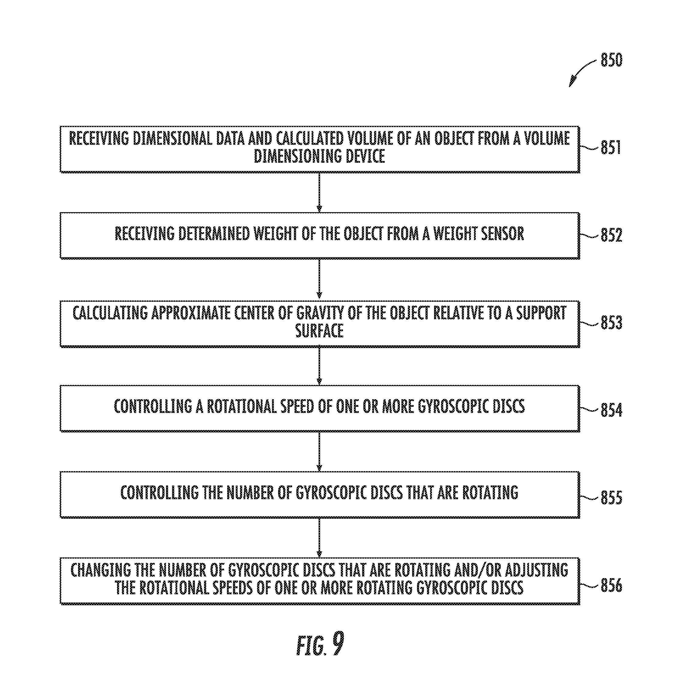
FIG. 9 discloses an embodiment of a method 850 of controlling a gyroscopically stabilized industrial vehicle 1 comprising a processor 510 being operable to: receive the dimensions and calculated volume of the object 600 from the volume dimensioning device 300 at block 851, and receive the determined weight of the object 600 from the weight sensor 400 at block 852; perform a calculation of the approximate center of gravity of the object 600 based on the dimensions, calculated volume and determined weight of the object 600 in relation to a support surface (e.g. the floor) at block 853; control a spin velocity P of one or more gyroscopic discs 700 at block 854; control the number of gyroscopic discs 700 that are rotating at block 855; and responsive to the calculated approximate center of gravity and determined weight of the object 600, change the number of gyroscopic discs 700 that are rotating and/or adjust the spin velocity P of the one or more rotating gyroscopic discs 700 at block 856.
In a further embodiment, the processor 510 is operable to control a spin velocity P of the gyroscopic disc 700 based on changes in the calculation of an approximate center of gravity of the object 600 relative to a support surface (e.g. the floor).
In another embodiment, when a plurality of gyroscopic discs 700 are used, the processor 510 activates or deactivates all or a portion of the gyroscopic discs 700 in response to the calculated approximate center of gravity and determined weight of the object 600. For example, when a torque M created by all of the plurality of gyroscopic discs 700 rotating exceeds a needed stabilizing force due to an object 600 that weighs less than the currently produced torque M, the processor 510 will only activate (e.g. rotate) enough of the gyroscopic discs 700 to sufficiently stabilize the industrial vehicle 1, the activation being determined by calculating an optimal torque Min view of the object 600 weight based on the spin velocity P, total mass m, and radius r of the gyroscopic discs 700 (discussed above). Additionally, the processor 510 will control the speed at which the gyroscopic discs 700 are rotated through communicative control over the motor 720. By only activating a subset of the gyroscopic discs 700 rather than all of the gyroscopic discs 700, the energy efficiency of the industrial vehicle 1 is improved.
Advantages of the described industrial vehicle include, but are not limited to a reduction in the weight of the industrial vehicle while maintaining the same lifting capacity as a conventional industrial vehicle using heavy counterweights. Additionally, the industrial vehicle can use a smaller motor than the convention industrial vehicle, since the overall weight of the industrial vehicle has been reduced, correspondingly reducing operational costs by requiring less fuel.
Further, the industrial vehicle will provide a more stable platform over uneven surfaces. For example, when a conventional industrial vehicle encounters an uneven surface, such as a dip or pothole, the conventional industrial vehicle's tires will follow the uneven surface into the dip, causing the conventional industrial vehicle to rock or shudder. When the conventional industrial vehicle is, for example, a forklift, this rocking motion can destabilize heavy loads, and can cause the heavy load to topple. However, when the industrial vehicle 1, encounters an uneven surface, the inertial torque generated by the gyroscopic disc will serve to stabilize the industrial vehicle by resisting the tendency of the industrial vehicle to rock or shudder. Instead, the industrial vehicle may "float" over the uneven surface, or the tires will more slowly enter into the uneven surface, reducing any sudden jarring motions.
To supplement the present disclosure, this application incorporates entirely by reference the following patents, patent application publications, and patent applications: U.S. Pat. Nos. 6,832,725; 7,128,266; 7,159,783; 7,413,127; 7,726,575; 8,294,969; 8,317,105; 8,322,622; 8,366,005; 8,371,507; 8,376,233; 8,381,979; 8,390,909; 8,408,464; 8,408,468; 8,408,469; 8,424,768; 8,448,863; 8,457,013; 8,459,557; 8,469,272; 8,474,712; 8,479,992; 8,490,877; 8,517,271; 8,523,076; 8,528,818; 8,544,737; 8,548,242; 8,548,420; 8,550,335; 8,550,354; 8,550,357; 8,556,174; 8,556,176; 8,556,177; 8,559,767; 8,599,957; 8,561,895; 8,561,903; 8,561,905; 8,565,107; 8,571,307; 8,579,200; 8,583,924; 8,584,945; 8,587,595; 8,587,697; 8,588,869; 8,590,789; 8,596,539; 8,596,542; 8,596,543; 8,599,271; 8,599,957; 8,600,158; 8,600,167; 8,602,309; 8,608,053; 8,608,071; 8,611,309; 8,615,487; 8,616,454; 8,621,123; 8,622,303; 8,628,013; 8,628,015; 8,628,016; 8,629,926; 8,630,491; 8,635,309; 8,636,200; 8,636,212; 8,636,215; 8,636,224; 8,638,806; 8,640,958; 8,640,960; 8,643,717; 8,646,692; 8,646,694; 8,657,200; 8,659,397; 8,668,149; 8,678,285; 8,678,286; 8,682,077; 8,687,282; 8,692,927; 8,695,880; 8,698,949; 8,717,494; 8,717,494; 8,720,783; 8,723,804; 8,723,904; 8,727,223; 8,740,082; 8,740,085; 8,746,563; 8,750,445; 8,752,766; 8,756,059; 8,757,495; 8,760,563; 8,763,909; 8,777,108; 8,777,109; 8,779,898; 8,781,520; 8,783,573; 8,789,757; 8,789,758; 8,789,759; 8,794,520; 8,794,522; 8,794,525; 8,794,526; 8,798,367; 8,807,431; 8,807,432; 8,820,630; 8,822,848; 8,824,692; 8,824,696; 8,842,849; 8,844,822; 8,844,823; 8,849,019; 8,851,383; 8,854,633; 8,866,963; 8,868,421; 8,868,519; 8,868,802; 8,868,803; 8,870,074; 8,879,639; 8,880,426; 8,881,983; 8,881,987; 8,903,172; 8,908,995; 8,910,870; 8,910,875; 8,914,290; 8,914,788; 8,915,439; 8,915,444; 8,916,789; 8,918,250; 8,918,564; 8,925,818; 8,939,374; 8,942,480; 8,944,313; 8,944,327; 8,944,332; 8,950,678; 8,967,468; 8,971,346; 8,976,030; 8,976,368; 8,978,981; 8,978,983; 8,978,984; 8,985,456; 8,985,457; 8,985,459; 8,985,461; 8,988,578; 8,988,590; 8,991,704; 8,996,194; 8,996,384; 9,002,641; 9,007,368; 9,010,641; 9,015,513; 9,016,576; 9,022,288; 9,030,964; 9,033,240; 9,033,242; 9,036,054; 9,037,344; 9,038,911; 9,038,915; 9,047,098; 9,047,359; 9,047,420; 9,047,525; 9,047,531; 9,053,055; 9,053,378; 9,053,380; 9,058,526; 9,064,165; 9,064,165; 9,064,167; 9,064,168; 9,064,254; 9,066,032; 9,070,032; 9,076,459; 9,079,423; 9,080,856; 9,082,023; 9,082,031; 9,084,032; 9,087,250; 9,092,681; 9,092,682; 9,092,683; 9,093,141; 9,098,763; 9,104,929; 9,104,934; 9,107,484; 9,111,159; 9,111,166; 9,135,483; 9,137,009; 9,141,839; 9,147,096; 9,148,474; 9,158,000; 9,158,340; 9,158,953; 9,159,059; 9,165,174; 9,171,543; 9,183,425; 9,189,669; 9,195,844; 9,202,458; 9,208,366; 9,208,367; 9,219,836; 9,224,024; 9,224,027; 9,230,140; 9,235,553; 9,239,950; 9,245,492; 9,248,640; 9,250,652; 9,250,712; 9,251,411; 9,258,033; 9,262,633; 9,262,660; 9,262,662; 9,269,036; 9,270,782; 9,274,812; 9,275,388; 9,277,668; 9,280,693; 9,286,496; 9,298,964; 9,301,427; 9,313,377; 9,317,037; 9,319,548; 9,342,723; 9,361,882; 9,365,381; 9,373,018; 9,375,945; 9,378,403; 9,383,848; 9,384,374; 9,390,304; 9,390,596; 9,411,386; 9,412,242; 9,418,269; 9,418,270; 9,465,967; 9,423,318; 9,424,454; 9,436,860; 9,443,123; 9,443,222; 9,454,689; 9,464,885; 9,465,967; 9,478,983; 9,481,186; 9,487,113; 9,488,986; 9,489,782; 9,490,540; 9,491,729; 9,497,092; 9,507,974; 9,519,814; 9,521,331; 9,530,038; 9,572,901; 9,558,386; 9,606,581; 9,646,189; 9,646,191; 9,652,648; 9,652,653; 9,656,487; 9,659,198; 9,680,282; 9,697,401; 9,701,140; U.S. Design Pat. No. D702,237; U.S. Design Pat. No. D716,285; U.S. Design Pat. No. D723,560; U.S. Design Pat. No. D730,357; U.S. Design Pat. No. D730,901; U.S. Design Pat. No. D730,902; U.S. Design Pat. No. D734,339; U.S. Design Pat. No. D737,321; U.S. Design Pat. No. D754,205; U.S. Design Pat. No. D754,206; U.S. Design Pat. No. D757,009; U.S. Design Pat. No. D760,719; U.S. Design Pat. No. D762,604; U.S. Design Pat. No. D766,244; U.S. Design Pat. No. D777,166; U.S. Design Pat. No. D771,631; U.S. Design Pat. No. D783,601; U.S. Design Pat. No. D785,617; U.S. Design Pat. No. D785,636; U.S. Design Pat. No. D790,505; U.S. Design Pat. No. D790,546; International Publication No. 2013/163789; U.S. Patent Application Publication No. 2008/0185432; U.S. Patent Application Publication No. 2009/0134221; U.S. Patent Application Publication No. 2010/0177080; U.S. Patent Application Publication No. 2010/0177076; U.S. Patent Application Publication No. 2010/0177707; U.S. Patent Application Publication No. 2010/0177749; U.S. Patent Application Publication No. 2010/0265880; U.S. Patent Application Publication No. 2011/0202554; U.S. Patent Application Publication No. 2012/0111946; U.S. Patent Application Publication No. 2012/0168511; U.S. Patent Application Publication No. 2012/0168512; U.S. Patent Application Publication No. 2012/0193423; U.S. Patent Application Publication No. 2012/0194692; U.S. Patent Application Publication No. 2012/0203647; U.S. Patent Application Publication No. 2012/0223141; U.S. Patent Application Publication No. 2012/0228382; U.S. Patent Application Publication No. 2012/0248188; U.S. Patent Application Publication No. 2013/0043312; U.S. Patent Application Publication No. 2013/0082104; U.S. Patent Application Publication No. 2013/0175341; U.S. Patent Application Publication No. 2013/0175343; U.S. Patent Application Publication No. 2013/0257744; U.S. Patent Application Publication No. 2013/0257759; U.S. Patent Application Publication No. 2013/0270346; U.S. Patent Application Publication No. 2013/0292475; U.S. Patent Application Publication No. 2013/0292477; U.S. Patent Application Publication No. 2013/0293539; U.S. Patent Application Publication No. 2013/0293540; U.S. Patent Application Publication No. 2013/0306728; U.S. Patent Application Publication No. 2013/0306731; U.S. Patent Application Publication No. 2013/0307964; U.S. Patent Application Publication No. 2013/0308625; U.S. Patent Application Publication No. 2013/0313324; U.S. Patent Application Publication No. 2013/0332996; U.S. Patent Application Publication No. 2014/0001267; U.S. Patent Application Publication No. 2014/0025584; U.S. Patent Application Publication No. 2014/0034734; U.S. Patent Application Publication No. 2014/0036848; U.S. Patent Application Publication No. 2014/0039693; U.S. Patent Application Publication No. 2014/0049120; U.S. Patent Application Publication No. 2014/0049635; U.S. Patent Application Publication No. 2014/0061306; U.S. Patent Application Publication No. 2014/0063289; U.S. Patent Application Publication No. 2014/0066136; U.S. Patent Application Publication No. 2014/0067692; U.S. Patent Application Publication No. 2014/0070005; U.S. Patent Application Publication No. 2014/0071840; U.S. Patent Application Publication No. 2014/0074746; U.S. Patent Application Publication No. 2014/0076974; U.S. Patent Application Publication No. 2014/0097249; U.S. Patent Application Publication No. 2014/0098792; U.S. Patent Application Publication No. 2014/0100813; U.S. Patent Application Publication No. 2014/0103115; U.S. Patent Application Publication No. 2014/0104413; U.S. Patent Application Publication No. 2014/0104414; U.S. Patent Application Publication No. 2014/0104416; U.S. Patent Application Publication No. 2014/0106725; U.S. Patent Application Publication No. 2014/0108010; U.S. Patent Application Publication No. 2014/0108402; U.S. Patent Application Publication No. 2014/0110485; U.S. Patent Application Publication No. 2014/0125853; U.S. Patent Application Publication No. 2014/0125999; U.S. Patent Application Publication No. 2014/0129378; U.S. Patent Application Publication No. 2014/0131443; U.S. Patent Application Publication No. 2014/0133379; U.S. Patent Application Publication No. 2014/0136208; U.S. Patent Application Publication No. 2014/0140585; U.S. Patent Application Publication No. 2014/0152882; U.S. Patent Application Publication No. 2014/0158770; U.S. Patent Application Publication No. 2014/0159869; U.S. Patent Application Publication No. 2014/0166759; U.S. Patent Application Publication No. 2014/0168787; U.S. Patent Application Publication No. 2014/0175165; U.S. Patent Application Publication No. 2014/0191684; U.S. Patent Application Publication No. 2014/0191913; U.S. Patent Application Publication No. 2014/0197304; U.S. Patent Application Publication No. 2014/0214631; U.S. Patent Application Publication No. 2014/0217166; U.S. Patent Application Publication No. 2014/0231500; U.S. Patent Application Publication No. 2014/0247315; U.S. Patent Application Publication No. 2014/0263493; U.S. Patent Application Publication No. 2014/0263645; U.S. Patent Application Publication No. 2014/0270196; U.S. Patent Application Publication No. 2014/0270229; U.S. Patent Application Publication No. 2014/0278387; U.S. Patent Application Publication No. 2014/0288933; U.S. Patent Application Publication No. 2014/0297058; U.S. Patent Application Publication No. 2014/0299665; U.S. Patent Application Publication No. 2014/0332590; U.S. Patent Application Publication No. 2014/0351317; U.S. Patent Application Publication No. 2014/0362184; U.S. Patent Application Publication No. 2014/0363015; U.S. Patent Application Publication No. 2014/0369511; U.S. Patent Application Publication No. 2014/0374483; U.S. Patent Application Publication No. 2014/0374485; U.S. Patent Application Publication No. 2015/0001301; U.S. Patent Application Publication No. 2015/0001304; U.S. Patent Application Publication No. 2015/0009338; U.S. Patent Application Publication No. 2015/0014416; U.S. Patent Application Publication No. 2015/0021397; U.S. Patent Application Publication No. 2015/0028104; U.S. Patent Application Publication No. 2015/0029002; U.S. Patent Application Publication No. 2015/0032709; U.S. Patent Application Publication No. 2015/0039309; U.S. Patent Application Publication No. 2015/0039878; U.S. Patent Application Publication No. 2015/0040378; U.S. Patent Application Publication No. 2015/0049347; U.S. Patent Application Publication No. 2015/0051992; U.S. Patent Application Publication No. 2015/0053769; U.S. Patent Application Publication No. 2015/0062366; U.S. Patent Application Publication No. 2015/0063215; U.S. Patent Application Publication No. 2015/0088522; U.S. Patent Application Publication No. 2015/0096872; U.S. Patent Application Publication No. 2015/0100196; U.S. Patent Application Publication No. 2015/0102109; U.S. Patent Application Publication No. 2015/0115035; U.S. Patent Application Publication No. 2015/0127791; U.S. Patent Application Publication No. 2015/0128116; U.S. Patent Application Publication No. 2015/0133047; U.S. Patent Application Publication No. 2015/0134470; U.S. Patent Application Publication No. 2015/0136851; U.S. Patent Application Publication No. 2015/0142492; U.S. Patent Application Publication No. 2015/0144692; U.S. Patent Application Publication No. 2015/0144698; U.S. Patent Application Publication No. 2015/0149946; U.S. Patent Application Publication No. 2015/0161429; U.S. Patent Application Publication No. 2015/0178523; U.S. Patent Application Publication No. 2015/0178537; U.S. Patent Application Publication No. 2015/0178685; U.S. Patent Application Publication No. 2015/0181109; U.S. Patent Application Publication No. 2015/0199957; U.S. Patent Application Publication No. 2015/0210199; U.S. Patent Application Publication No. 2015/0212565; U.S. Patent Application Publication No. 2015/0213647; U.S. Patent Application Publication No. 2015/0220753; U.S. Patent Application Publication No. 2015/0220901; U.S. Patent Application Publication No. 2015/0227189; U.S. Patent Application Publication No. 2015/0236984; U.S. Patent Application Publication No. 2015/0239348; U.S. Patent Application Publication No. 2015/0242658; U.S. Patent Application Publication No. 2015/0248572; U.S. Patent Application Publication No. 2015/0254485; U.S. Patent Application Publication No. 2015/0261643; U.S. Patent Application Publication No. 2015/0264624; U.S. Patent Application Publication No. 2015/0268971; U.S. Patent Application Publication No. 2015/0269402; U.S. Patent Application Publication No. 2015/0288689; U.S. Patent Application Publication No. 2015/0288896; U.S. Patent Application Publication No. 2015/0310243; U.S. Patent Application Publication No. 2015/0310244; U.S. Patent Application Publication No. 2015/0310389; U.S. Patent Application Publication No. 2015/0312780; U.S. Patent Application Publication No. 2015/0327012; U.S. Patent Application Publication No. 2016/0014251; U.S. Patent Application Publication No. 2016/0025697; U.S. Patent Application Publication No. 2016/0026838; U.S. Patent Application Publication No. 2016/0026839; U.S. Patent Application Publication No. 2016/0040982; U.S. Patent Application Publication No. 2016/0042241; U.S. Patent Application Publication No. 2016/0057230; U.S. Patent Application Publication No. 2016/0062473; U.S. Patent Application Publication No. 2016/0070944; U.S. Patent Application Publication No. 2016/0092805; U.S. Patent Application Publication No. 2016/0101936; U.S. Patent Application Publication No. 2016/0104019; U.S. Patent Application Publication No. 2016/0104274; U.S. Patent Application Publication No. 2016/0109219; U.S. Patent Application Publication No. 2016/0109220; U.S. Patent Application Publication No. 2016/0109224; U.S. Patent Application Publication No. 2016/0112631; U.S. Patent Application Publication No. 2016/0112643; U.S. Patent Application Publication No. 2016/0117627; U.S. Patent Application Publication No. 2016/0124516; U.S. Patent Application Publication No. 2016/0125217; U.S. Patent Application Publication No. 2016/0125342; U.S. Patent Application Publication No. 2016/0125873; U.S. Patent Application Publication No. 2016/0133253; U.S. Patent Application Publication No. 2016/0171597; U.S. Patent Application Publication No. 2016/0171666; U.S. Patent Application Publication No. 2016/0171720; U.S. Patent Application Publication No. 2016/0171775; U.S. Patent Application Publication No. 2016/0171777; U.S. Patent Application Publication No. 2016/0174674; U.S. Patent Application Publication No. 2016/0178479; U.S. Patent Application Publication No. 2016/0178685; U.S. Patent Application Publication No. 2016/0178707; U.S. Patent Application Publication No. 2016/0179132; U.S. Patent Application Publication No. 2016/0179143; U.S. Patent Application Publication No. 2016/0179368; U.S. Patent Application Publication No. 2016/0179378; U.S. Patent Application Publication No. 2016/0180130; U.S. Patent Application Publication No. 2016/0180133; U.S. Patent Application Publication No. 2016/0180136; U.S. Patent Application Publication No. 2016/0180594; U.S. Patent Application Publication No. 2016/0180663; U.S. Patent Application Publication No. 2016/0180678; U.S. Patent Application Publication No. 2016/0180713; U.S. Patent Application Publication No. 2016/0185136; U.S. Patent Application Publication No. 2016/0185291; U.S. Patent Application Publication No. 2016/0186926; U.S. Patent Application Publication No. 2016/0188861; U.S. Patent Application Publication No. 2016/0188939; U.S. Patent Application Publication No. 2016/0188940; U.S. Patent Application Publication No. 2016/0188941; U.S. Patent Application Publication No. 2016/0188942; U.S. Patent Application Publication No. 2016/0188943; U.S. Patent Application Publication No. 2016/0188944; U.S. Patent Application Publication No. 2016/0189076; U.S. Patent Application Publication No. 2016/0189087; U.S. Patent Application Publication No. 2016/0189088; U.S. Patent Application Publication No. 2016/0189092; U.S. Patent Application Publication No. 2016/0189284; U.S. Patent Application Publication No. 2016/0189288; U.S. Patent Application Publication No. 2016/0189366; U.S. Patent Application Publication No. 2016/0189443; U.S. Patent Application Publication No. 2016/0189447; U.S. Patent Application Publication No. 2016/0189489; U.S. Patent Application Publication No. 2016/0192051; U.S. Patent Application Publication No. 2016/0202951; U.S. Patent Application Publication No. 2016/0202958; U.S. Patent Application Publication No. 2016/0202959; U.S. Patent Application Publication No. 2016/0203021; U.S. Patent Application Publication No. 2016/0203429; U.S. Patent Application Publication No. 2016/0203797; U.S. Patent Application Publication No. 2016/0203820; U.S. Patent Application Publication No. 2016/0204623; U.S. Patent Application Publication No. 2016/0204636; U.S. Patent Application Publication No. 2016/0204638; U.S. Patent Application Publication No. 2016/0227912; U.S. Patent Application Publication No. 2016/0232891; U.S. Patent Application Publication No. 2016/0292477; U.S. Patent Application Publication No. 2016/0294779; U.S. Patent Application Publication No. 2016/0306769; U.S. Patent Application Publication No. 2016/0314276; U.S. Patent Application Publication No. 2016/0314294; U.S. Patent Application Publication No. 2016/0316190; U.S. Patent Application Publication No. 2016/0323310; U.S. Patent Application Publication No. 2016/0325677; U.S. Patent Application Publication No. 2016/0327614; U.S. Patent Application Publication No. 2016/0327930; U.S. Patent Application Publication No. 2016/0328762; U.S. Patent Application Publication No. 2016/0330218; U.S. Patent Application Publication No. 2016/0343163; U.S. Patent Application Publication No. 2016/0343176; U.S. Patent Application Publication No. 2016/0364914; U.S. Patent Application Publication No. 2016/0370220; U.S. Patent Application Publication No. 2016/0372282; U.S. Patent Application Publication No. 2016/0373847; U.S. Patent Application
Publication No. 2016/0377414; U.S. Patent Application Publication No. 2016/0377417; U.S. Patent Application Publication No. 2017/0010141; U.S. Patent Application Publication No. 2017/0010328; U.S. Patent Application Publication No. 2017/0010780; U.S. Patent Application Publication No. 2017/0016714; U.S. Patent Application Publication No. 2017/0018094; U.S. Patent Application Publication No. 2017/0046603; U.S. Patent Application Publication No. 2017/0047864; U.S. Patent Application Publication No. 2017/0053146; U.S. Patent Application Publication No. 2017/0053147; U.S. Patent Application Publication No. 2017/0053647; U.S. Patent Application Publication No. 2017/0055606; U.S. Patent Application Publication No. 2017/0060316; U.S. Patent Application Publication No. 2017/0061961; U.S. Patent Application Publication No. 2017/0064634; U.S. Patent Application Publication No. 2017/0083730; U.S. Patent Application Publication No. 2017/0091502; U.S. Patent Application Publication No. 2017/0091706; U.S. Patent Application Publication No. 2017/0091741; U.S. Patent Application Publication No. 2017/0091904; U.S. Patent Application Publication No. 2017/0092908; U.S. Patent Application Publication No. 2017/0094238; U.S. Patent Application Publication No. 2017/0098947; U.S. Patent Application Publication No. 2017/0100949; U.S. Patent Application Publication No. 2017/0108838; U.S. Patent Application Publication No. 2017/0108895; U.S. Patent Application Publication No. 2017/0118355; U.S. Patent Application Publication No. 2017/0123598; U.S. Patent Application Publication No. 2017/0124369; U.S. Patent Application Publication No. 2017/0124396; U.S. Patent Application Publication No. 2017/0124687; U.S. Patent Application Publication No. 2017/0126873; U.S. Patent Application Publication No. 2017/0126904; U.S. Patent Application Publication No. 2017/0139012; U.S. Patent Application Publication No. 2017/0140329; U.S. Patent Application Publication No. 2017/0140731; U.S. Patent Application Publication No. 2017/0147847; U.S. Patent Application Publication No. 2017/0150124; U.S. Patent Application Publication No. 2017/0169198; U.S. Patent Application Publication No. 2017/0171035; U.S. Patent Application Publication No. 2017/0171703; U.S. Patent Application Publication No. 2017/0171803; U.S. Patent Application Publication No. 2017/0180359; U.S. Patent Application Publication No. 2017/0180577; U.S. Patent Application Publication No. 2017/0181299; U.S. Patent Application Publication No. 2017/0190192; U.S. Patent Application Publication No. 2017/0193432; U.S. Patent Application Publication No. 2017/0193461; U.S. Patent Application Publication No. 2017/0193727; U.S. Patent Application Publication No. 2017/0199266; U.S. Patent Application Publication No. 2017/0200108; U.S. Patent Application Publication No. 2017/0200275;
* * *
In the specification and/or figures, typical embodiments of the invention have been disclosed. The present invention is not limited to such exemplary embodiments. The use of the term "and/or" includes any and all combinations of one or more of the associated listed items. The figures are schematic representations and so are not necessarily drawn to scale. Unless otherwise noted, specific terms have been used in a generic and descriptive sense and not for purposes of limitation.
* * * * *
References
D00000
D00001
D00002
D00003
D00004
D00005
D00006
XML
uspto.report is an independent third-party trademark research tool that is not affiliated, endorsed, or sponsored by the United States Patent and Trademark Office (USPTO) or any other governmental organization. The information provided by uspto.report is based on publicly available data at the time of writing and is intended for informational purposes only.
While we strive to provide accurate and up-to-date information, we do not guarantee the accuracy, completeness, reliability, or suitability of the information displayed on this site. The use of this site is at your own risk. Any reliance you place on such information is therefore strictly at your own risk.
All official trademark data, including owner information, should be verified by visiting the official USPTO website at www.uspto.gov. This site is not intended to replace professional legal advice and should not be used as a substitute for consulting with a legal professional who is knowledgeable about trademark law.