Golf club heads and methods to manufacture golf club heads
Parsons , et al.
U.S. patent number 10,617,918 [Application Number 16/290,610] was granted by the patent office on 2020-04-14 for golf club heads and methods to manufacture golf club heads. This patent grant is currently assigned to PARSONS XTREME GOLF, LLC. The grantee listed for this patent is Parsons Xtreme Golf, LLC. Invention is credited to Michael R. Nicolette, Robert R. Parsons, Bradley D. Schweigert.


| United States Patent | 10,617,918 |
| Parsons , et al. | April 14, 2020 |
Golf club heads and methods to manufacture golf club heads
Abstract
Embodiments of golf club heads and methods to manufacture golf club heads are generally described herein. In one example, a golf club head may include a body portion having a front portion, a rear portion, a toe portion, a heel portion, a top portion, a bottom portion having an outer surface, and a plurality of ports. Each port may be defined by a bore having a bore opening on the outer surface of the bottom portion and a bore wall extending into the body portion from the bore opening. The plurality of ports may include a first set of ports configured in a first arc having at least three adjacent ports and a second set of ports configured in a second arc having at least three adjacent ports. Other examples and embodiments may be described and claimed.
| Inventors: | Parsons; Robert R. (Scottsdale, AZ), Schweigert; Bradley D. (Anthem, AZ), Nicolette; Michael R. (Scottsdale, AZ) | ||||||||||
|---|---|---|---|---|---|---|---|---|---|---|---|
| Applicant: |
|
||||||||||
| Assignee: | PARSONS XTREME GOLF, LLC
(Scottsdale, AZ) |
||||||||||
| Family ID: | 66949417 | ||||||||||
| Appl. No.: | 16/290,610 | ||||||||||
| Filed: | March 1, 2019 |
Prior Publication Data
| Document Identifier | Publication Date | |
|---|---|---|
| US 20190192933 A1 | Jun 27, 2019 | |
Related U.S. Patent Documents
| Application Number | Filing Date | Patent Number | Issue Date | ||
|---|---|---|---|---|---|
| 15875416 | Jan 19, 2018 | 10293220 | |||
| 15446842 | Mar 1, 2017 | 9895582 | |||
| 15377120 | Dec 13, 2016 | 9802087 | |||
| 14939849 | Nov 12, 2015 | 9555295 | |||
| 14615606 | Feb 6, 2015 | 9199140 | |||
| 16290610 | |||||
| 15875496 | Jan 19, 2018 | 10252123 | |||
| 15457627 | Mar 13, 2017 | 9895583 | |||
| 15189806 | Jun 22, 2016 | 9636554 | |||
| 14667546 | Mar 24, 2015 | 9399158 | |||
| 14615606 | Feb 6, 2015 | 9199140 | |||
| 62042155 | Aug 26, 2014 | ||||
| 62048693 | Sep 10, 2014 | ||||
| 62101543 | Jan 9, 2015 | ||||
| 62105123 | Jan 19, 2015 | ||||
| 62109510 | Jan 29, 2015 | ||||
| Current U.S. Class: | 1/1 |
| Current CPC Class: | A63B 53/04 (20130101); A63B 60/02 (20151001); A63B 53/0466 (20130101); A63B 1/00 (20130101); A63B 53/0408 (20200801); A63B 2053/0491 (20130101); A63B 2053/0408 (20130101); A63B 53/0412 (20200801); A63B 53/0433 (20200801); A63B 2053/0412 (20130101); A63B 2053/0433 (20130101); A63B 2071/0694 (20130101) |
| Current International Class: | A63B 53/04 (20150101); A63B 60/02 (20150101); A63B 1/00 (20060101) |
| Field of Search: | ;473/344-339,341 |
References Cited [Referenced By]
U.S. Patent Documents
| 1133129 | March 1915 | Govan |
| 1269745 | June 1918 | Robertson |
| 1306029 | June 1919 | Robertson |
| D55867 | July 1920 | Mattern |
| 1534600 | April 1925 | Mattern |
| 1538312 | May 1925 | Beat |
| D138437 | August 1944 | Link |
| D138438 | August 1944 | Link |
| D138442 | August 1944 | Link |
| 3652094 | March 1972 | Glover |
| D240748 | July 1976 | Bock |
| 4085934 | April 1978 | Churchward |
| D253778 | December 1979 | Madison |
| D307783 | May 1990 | Iinuma |
| D326885 | June 1992 | Paul |
| 5219408 | June 1993 | Sun |
| D351883 | October 1994 | Serrano |
| 5518243 | May 1996 | Redman |
| D378111 | February 1997 | Parente |
| D384120 | September 1997 | Parente |
| 5788584 | August 1998 | Parente |
| D400625 | November 1998 | Nicolette |
| D400627 | November 1998 | Nicolette |
| D405489 | February 1999 | Nicolette |
| D405492 | February 1999 | Nicolette |
| D444830 | July 2001 | Nicolette |
| D478140 | August 2003 | Burrows |
| 6638182 | October 2003 | Kosmatka |
| 6773360 | August 2004 | Willett |
| D508969 | August 2005 | Hasebe |
| D513051 | December 2005 | Lorenz, Jr. |
| D514179 | January 2006 | Chen |
| D514185 | January 2006 | Barez et al. |
| D520586 | May 2006 | Bingman |
| D522077 | May 2006 | Jertson |
| D522601 | June 2006 | Schweigert et al. |
| D523498 | June 2006 | Chen et al. |
| D526694 | August 2006 | Jertson |
| 7121956 | October 2006 | Lo |
| D534599 | January 2007 | Beach |
| 7166040 | January 2007 | Hoffman |
| D536401 | February 2007 | Kawami |
| D536403 | February 2007 | Kawami |
| 7186190 | March 2007 | Beach |
| 7223180 | May 2007 | Willett |
| 7261646 | August 2007 | De Shiell |
| D563498 | March 2008 | Jertson |
| D564054 | March 2008 | Jertson |
| D564055 | March 2008 | Jertson |
| 7338388 | March 2008 | Schweigert |
| 7347794 | March 2008 | Schweigert |
| D567317 | April 2008 | Jertson et al. |
| D569933 | May 2008 | Jertson |
| D569934 | May 2008 | Jertson et al. |
| D569935 | May 2008 | Chen |
| D569936 | May 2008 | Chen |
| D569942 | May 2008 | Jertson |
| D570937 | June 2008 | Chen |
| D570938 | June 2008 | Jertson |
| 7407447 | August 2008 | Beach |
| 7410425 | August 2008 | Willett |
| 7410426 | August 2008 | Willett |
| 7419441 | September 2008 | Hoffman |
| 7448963 | November 2008 | Beach |
| 7448964 | November 2008 | Schweigert |
| 7494425 | February 2009 | De Shiell |
| 7530904 | May 2009 | Beach |
| D594520 | June 2009 | Chen |
| D594521 | June 2009 | Jertson |
| D594919 | June 2009 | Chen |
| 7540811 | June 2009 | Beach |
| D597620 | August 2009 | Toulon |
| 7568985 | August 2009 | Beach |
| 7578753 | August 2009 | Beach |
| D600297 | September 2009 | Jertson |
| 7584531 | September 2009 | Schweigert |
| 7588502 | September 2009 | Nishino |
| 7591738 | September 2009 | Beach |
| D603472 | November 2009 | Chen |
| 7611424 | November 2009 | Nagai |
| 7621823 | November 2009 | Beach |
| D605715 | December 2009 | Toulon |
| 7632194 | December 2009 | Beach |
| 7658686 | February 2010 | Soracco |
| 7713142 | May 2010 | Hoffman |
| 7717804 | May 2010 | Beach |
| 7717805 | May 2010 | Beach |
| D618746 | June 2010 | Jertson |
| D618747 | June 2010 | Chen |
| D618753 | June 2010 | Jertson |
| D618754 | June 2010 | Schweigert et al. |
| 7744484 | June 2010 | Chao |
| 7798203 | September 2010 | Schweigert |
| 7846041 | December 2010 | Beach |
| D635626 | April 2011 | Nicolette |
| 7927229 | April 2011 | Jertson |
| D638893 | May 2011 | Schweigert et al. |
| D638896 | May 2011 | Schweigert et al. |
| 7963861 | June 2011 | Beach |
| 8012038 | September 2011 | Beach |
| D647585 | October 2011 | Jertson et al. |
| 8096896 | January 2012 | De Schiell |
| D661751 | June 2012 | Jertson |
| D661756 | June 2012 | Jertson |
| 8197357 | June 2012 | Rice |
| 8202175 | June 2012 | Ban |
| 8257196 | September 2012 | Abbott |
| 8257197 | September 2012 | Schweigert |
| 8262506 | September 2012 | Watson |
| 8287402 | October 2012 | De Shiell |
| D673630 | January 2013 | Schweigert |
| D673632 | January 2013 | Chen |
| 8371957 | February 2013 | Schweigert |
| D680179 | April 2013 | Chen |
| 8414422 | April 2013 | Peralta |
| 8485919 | July 2013 | Rice |
| D691230 | October 2013 | Jertson |
| 8562457 | October 2013 | Beach |
| 8608587 | December 2013 | Henrikson |
| 8628431 | January 2014 | Schweigert |
| 8663026 | March 2014 | Blowers |
| 8777778 | July 2014 | Solheim |
| 8784232 | July 2014 | Jertson |
| 8790196 | July 2014 | Solheim |
| 8808108 | August 2014 | Schweigert |
| D712989 | September 2014 | Gillig |
| 8826512 | September 2014 | Schweigert |
| 8858362 | October 2014 | Leposky |
| 8900069 | December 2014 | Beach |
| 8926449 | January 2015 | Sato |
| 8961336 | February 2015 | Parsons |
| D724164 | March 2015 | Schweigert et al. |
| D729892 | May 2015 | Schweigert |
| D733234 | June 2015 | Nicolette |
| 9199140 | December 2015 | Schweigert |
| 9199143 | December 2015 | Parsons |
| D753251 | April 2016 | Schweigert |
| D756471 | May 2016 | Schweigert |
| 9352197 | May 2016 | Parsons |
| D760334 | June 2016 | Schweigert |
| 9399158 | July 2016 | Parsons |
| 9427634 | August 2016 | Parsons |
| 9452325 | September 2016 | Deshiell |
| 9555295 | January 2017 | Schweigert |
| 9636554 | May 2017 | Parsons |
| 9839821 | December 2017 | Deshiell |
| 2005/0101408 | May 2005 | Sanchez |
| 2006/0105856 | May 2006 | Lo |
| 2006/0111200 | May 2006 | Poynor |
| 2007/0293344 | December 2007 | Davis |
| 2008/0004133 | January 2008 | Schweigert |
| 2008/0188322 | August 2008 | Anderson |
| 2008/0261715 | October 2008 | Carter |
| 2009/0029795 | January 2009 | Schweigert |
| 2009/0069113 | March 2009 | Nakano |
| 2010/0144461 | June 2010 | Ban |
| 2011/0143858 | June 2011 | Peralta |
| 2012/0071269 | March 2012 | Rahrig |
| 2012/0202615 | August 2012 | Beach |
| 2013/0303304 | November 2013 | Sato |
| 2015/0231454 | August 2015 | Parsons |
| 2002535056 | Oct 2002 | JP | |||
| 2005287679 | Oct 2005 | JP | |||
| 2006223331 | Aug 2006 | JP | |||
| 2007136068 | Jun 2007 | JP | |||
| 2010069106 | Apr 2010 | JP | |||
| 2010136772 | Jun 2010 | JP | |||
Other References
|
International Search Report and Written Opinion Received in Connection With the Corresponding Application No. PCT/US2015/016666, dated May 14, 2015 (8 Pages). cited by applicant . International Search Report and Written Opinion Issued in Connection With Corresponding Application No. PCT/US15/42484 dated Oct. 19, 2015 (12 Pages). cited by applicant . International Search Report and Written Opinion Issued in Connection With Corresponding Application No. PCTUS2015042282 dated Oct. 13, 2015 (12 Pages). cited by applicant . U.S. Appl. No. 29/512,313, Nicolette, "Golf Club Head," Filed Dec. 18, 2018, Cited by Applicant. cited by applicant . Wall, Jonathan, "Details: Phil'S Prototype Mack Daddy PM-Grind Wedge," (http://www.pgatour.com/equipmentreport/2015/01/21/callaway-wedge.html), www.pgatour.com, PGA Tour, Inc., Published Jan. 21, 2015, Cited by Applicant. cited by applicant. |
Primary Examiner: Layno; Benjamin
Parent Case Text
CROSS REFERENCE
This application is a continuation-in-part of application Ser. No. 15/875,416, filed Jan. 19, 2018, now U.S. Pat. No. 10,293,220, which is a continuation of application Ser. No. 15/446,842, filed Mar. 1, 2017, now U.S. Pat. No. 9,895,582, which is a continuation of application Ser. No. 15/377,120, filed Dec. 13, 2016, now U.S. Pat. No. 9,802,087, which is a continuation of application Ser. No. 14/939,849, filed Nov. 12, 2015, now U.S. Pat. No. 9,555,295, which is a continuation of application Ser. No. 14/615,606, filed Feb. 6, 2015, now U.S. Pat. No. 9,199,140.
This application is a continuation of application Ser. No. 15/875,496, filed Jan. 19, 2018, now U.S. Pat. No. 10,252,123, which is a continuation of application Ser. No. 15/457,627, filed Mar. 13, 2017, now U.S. Pat. No. 9,895,583, which is a continuation of application Ser. No. 15/189,806, filed Jun. 22, 2016, now U.S. Pat. No. 9,636,554, which is a continuation of application Ser. No. 14/667,546, filed Mar. 24, 2015, now U.S. Pat. No. 9,399,158, which is a continuation-in-part of application Ser. No. 14/615,606, filed Feb. 6, 2015, now U.S. Pat. No. 9,199,140, which claims the benefit of U.S. Provisional Application No. 62/042,155, filed Aug. 26, 2014, U.S. Provisional Application No. 62/048,693, filed Sep. 10, 2014, U.S. Provisional Application No. 62/101,543, filed Jan. 9, 2015, U.S. Provisional Application No. 62/105,123, filed Jan. 19, 2015, and U.S. Provisional Application No. 62/109,510, filed Jan. 29, 2015.
The disclosures of the above-referenced applications are incorporated herein by reference.
Claims
What is claimed is:
1. A golf club head comprising: a body portion having a front portion, a rear portion, a toe portion, a heel portion, a top portion, a bottom portion having an outer surface, and a plurality of ports, each port defined by a bore having a bore opening in the outer surface of the bottom portion and a bore wall extending into the body portion from the bore opening; and a plurality of weight portions, each port of the plurality of ports containing a weight portion of the plurality of weight portions, wherein the plurality of ports includes a first set of ports configured in a first arc extending from a location at or proximate to the toe portion to a location at or proximate to the heel portion and a second set of ports configured in a second arc extending from a location at or proximate to the toe portion to a location at or proximate to the heel portion, the first arc being closer to the front portion than the second arc, wherein the first set of ports includes at least three adjacent ports, and the second set of ports includes at least three adjacent ports, wherein the first set of ports are substantially similarly spaced apart, and the second set of ports are substantially similarly spaced apart.
2. A golf club head as defined in claim 1, wherein the first arc is convex relative to the front portion.
3. A golf club head as defined in claim 1, wherein the second arc is concave relative to the front portion.
4. A golf club head as defined in claim 1, wherein the first arc is convex relative to the front portion and the second arc is concave relative to the front portion.
5. A golf club head as defined in claim 1, wherein the first set of ports includes a greater number of the plurality of ports than the second set of ports.
6. A golf club head as defined in claim 1, wherein each pair of adjacent ports of the first set of ports are spaced apart by a nonadjustable distance of less than a diameter of either port of the pair of adjacent ports.
7. A golf club head as defined in claim 1, wherein each pair of adjacent ports of the second set of ports are spaced apart by a nonadjustable distance of less than a diameter of either port of the pair of adjacent ports.
8. A golf club head comprising: a body portion having a front portion, a rear portion, a toe portion, a heel portion, a top portion, a bottom portion having an outer surface, and a plurality of ports, each port defined by a bore having a bore opening in the outer surface of the bottom portion and a bore wall extending into the body portion from the bore opening; and a plurality of weight portions, each port of the plurality of ports containing a weight portion of the plurality of weight portions, wherein the plurality of ports includes a first set of ports configured in a first arc extending from a location at or proximate to the toe portion to a location at or proximate to the heel portion and a second set of ports configured in a second arc extending from a location at or proximate to the toe portion to a location at or proximate to the heel portion, the first arc being closer to the front portion than the second arc, wherein the first set of ports includes at least three adjacent ports, and the second set of ports includes at least three adjacent ports, wherein the golf club head has a volume between 100 cc and 400 cc.
9. A golf club head as defined in claim 8, wherein the first arc is convex relative to the front portion.
10. A golf club head as defined in claim 8, wherein the second arc is concave relative to the front portion.
11. A golf club head as defined in claim 8, wherein the first arc is convex relative to the front portion and the second arc is concave relative to the front portion.
12. A golf club head as defined in claim 8, wherein the first set of ports includes a greater number of the plurality of ports than the second set of ports.
13. A golf club head as defined in claim 8, wherein each pair of adjacent ports of the first set of ports are spaced apart by a nonadjustable distance of less than a diameter of either port of the pair of adjacent ports.
14. A golf club head as defined in claim 8, wherein each pair of adjacent ports of the second set of ports are spaced apart by a nonadjustable distance of less than a diameter of either port of the pair of adjacent ports.
15. A golf club head comprising: a body portion having a front portion, a rear portion, a toe portion, a heel portion, a top portion, a bottom portion having an outer surface, and a plurality of ports, each port defined by a bore having a bore opening in the outer surface of the bottom portion and a bore wall extending into the body portion from the bore opening; and a plurality of weight portions, each port of the plurality of ports containing a weight portion of the plurality of weight portions, wherein the plurality of ports includes a first set of ports configured in a first arc extending from a location at or proximate to the toe portion to a location at or proximate to the heel portion and a second set of ports configured in a second arc extending from a location at or proximate to the toe portion to a location at or proximate to the heel portion, the first arc being closer to the front portion than the second arc, wherein the first set of ports includes at least three adjacent ports, and the second set of ports includes at least three adjacent ports, wherein the golf club head has a mass between 100 grams and 350 grams.
16. A golf club head as defined in claim 15, wherein the first arc is convex relative to the front portion.
17. A golf club head as defined in claim 15, wherein the first arc is convex relative to the front portion and the second arc is concave relative to the front portion.
18. A golf club head as defined in claim 15, wherein the first set of ports includes a greater number of the plurality of ports than the second set of ports.
19. A golf club head as defined in claim 15, wherein each pair of adjacent ports of the first set of ports are spaced apart by a nonadjustable distance of less than a diameter of either port of the pair of adjacent ports.
20. A golf club head as defined in claim 15, wherein each pair of adjacent ports of the second set of ports are spaced apart by a nonadjustable distance of less than a diameter of either port of the pair of adjacent ports.
Description
COPYRIGHT AUTHORIZATION
The present disclosure may be subject to copyright protection. The copyright owner has no objection to the facsimile reproduction by anyone of the present disclosure and its related documents, as they appear in the Patent and Trademark Office patent files or records, but otherwise reserves all applicable copyrights.
FIELD
The present disclosure generally relates to sports equipment, and more particularly, to golf club heads and methods to manufacture golf club heads.
BACKGROUND
In golf, various factors may affect the distance and direction that a golf ball may travel. In particular, the center of gravity (CG) and/or the moment of inertia (MOI) of a golf club head may affect the launch angle, the spin rate, and the direction of the golf ball at impact. Such factors may vary significantly based the type of golf swing.
BRIEF DESCRIPTION OF THE DRAWINGS
FIG. 1 is top perspective view of an example golf club head according to an embodiment of the apparatus, methods, and articles of manufacture described herein.
FIG. 2 depicts a bottom perspective view of the example golf club head of FIG. 1.
FIG. 3 depicts a top view of the example golf club head of FIG. 1.
FIG. 4 depicts a bottom view of the example golf club head of FIG. 1.
FIG. 5 depicts a front view of the example golf club head of FIG. 1.
FIG. 6 depicts a rear view of the example golf club head of FIG. 1.
FIG. 7 depicts a toe view of the example golf club head of FIG. 1.
FIG. 8 depicts a heel view of the example golf club head of FIG. 1.
FIG. 9 depicts a bottom view of an example body portion of the example golf club head of FIG. 1.
FIG. 10 depicts a cross-sectional view of the example body portion of the example golf club head of FIG. 1.
FIG. 11 depicts two weight ports of the example golf club head of FIG. 1.
FIG. 12 depicts a top view of an example weight portion of the example golf club head of FIG. 1.
FIG. 13 depicts a side view of the example weight portion of FIG. 10.
FIG. 14 depicts example launch trajectory profiles of the example golf club head of FIG. 1.
FIG. 15 depicts a first weight configuration of the example weight portions.
FIG. 16 depicts a second weight configuration of the example weight portions.
FIG. 17 depicts a third weight configuration of the example weight portions.
FIG. 18 depicts a fourth weight configuration of the example weight portions.
FIG. 19 depicts an example launch trajectory profile of the example golf club head of FIG. 18.
FIG. 20 depicts one manner in which the example golf club heads described herein may be manufactured.
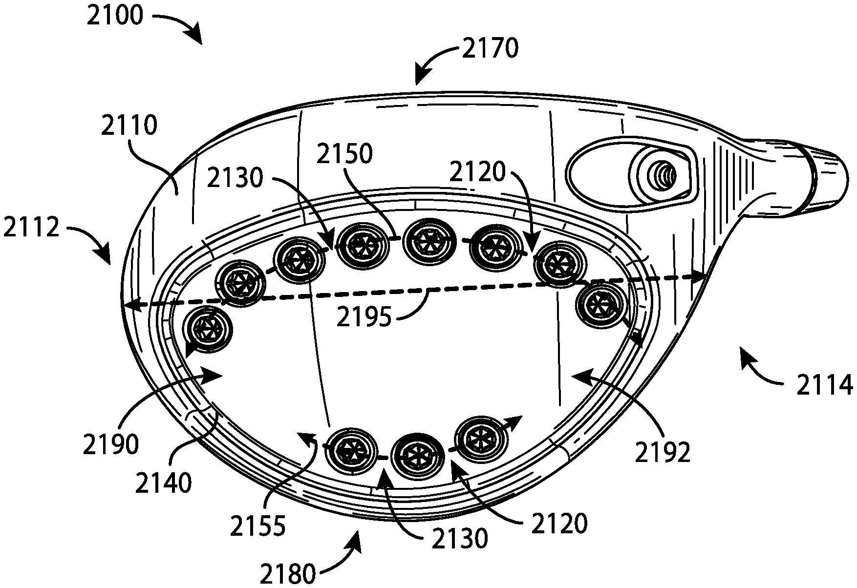
FIG. 21 depicts a bottom view of another example golf club head.
FIG. 22 depicts a bottom view of yet another example golf club head.
For simplicity and clarity of illustration, the drawing figures illustrate the general manner of construction, and descriptions and details of well-known features and techniques may be omitted to avoid unnecessarily obscuring the present disclosure. Additionally, elements in the drawing figures are not necessarily drawn to scale. For example, the dimensions of some of the elements in the figures may be exaggerated relative to other elements to help improve understanding of embodiments of the present disclosure.
DESCRIPTION
In general, golf club heads and methods to manufacture golf club heads are described herein. The apparatus, methods, and articles of manufacture described herein are not limited in this regard.
In the example of FIGS. 1-13, a golf club head 100 may include a body portion 110, and a plurality of weight portions 120, generally, shown as a first set of weight portions 210 (FIG. 2) and a second set of weight portions 220 (FIG. 2). The body portion 110 may include a top portion 130, a bottom portion 140, a toe portion 150, a heel portion 160, a front portion 170, and a rear portion 180. The bottom portion 140 may include a skirt portion 190 defined as a side portion of the golf club head 100 between the top portion 130 and the bottom portion 140 excluding the front portion 170 and extending across a periphery of the golf club head 100 from the toe portion 150, around the rear portion 180, and to the heel portion 160. The bottom portion 140 may include a transition region 230 and a weight port region 240. For example, the weight port region 240 may be a D-shape region. The weight port region 240 may include a plurality of weight ports 900 (FIG. 9) to receive the plurality of weight portions 120. The front portion 170 may include a face portion 175 to engage a golf ball (not shown). The body portion 110 may also include a hosel portion 165 to receive a shaft (not shown). Alternatively, the body portion 110 may include a bore instead of the hosel portion 165. For example, the body portion 110 may be made partially or entirely of an aluminum-based material, a magnesium-type material, a steel-based material, a titanium-based material, any combination thereof, or any other suitable material. In another example the body portion 110 may be made partially or entirely of a non-metal material such as a ceramic material, a composite material, any combination thereof, or any other suitable material.
The golf club head 100 may have a club head volume greater than or equal to 300 cubic centimeters (cm.sup.3 or cc). In one example, the golf club head 100 may be about 460 cc. Alternatively, the golf club head 100 may have a club head volume less than or equal to 300 cc. In particular, the golf club head 100 may have a club head volume between 100 cc and 200 cc. The club head volume of the golf club head 100 may be determined by using the weighted water displacement method (i.e., Archimedes Principle). For example, procedures defined by golf standard organizations and/or governing bodies such as the United States Golf Association (USGA) and/or the Royal and Ancient Golf Club of St. Andrews (R&A) may be used for measuring the club head volume of the golf club head 100. Although FIG. 1 may depict a particular type of club head (e.g., a driver-type club head), the apparatus, methods, and articles of manufacture described herein may be applicable to other types of club head (e.g., a fairway wood-type club head, a hybrid-type club head, an iron-type club head, a putter-type club head, etc.). The apparatus, methods, and articles of manufacture described herein are not limited in this regard.
Each of the first set of weight portions 210, generally shown as 405, 410, 415, 420, 425, 430, and 435 (FIG. 4), may be associated with a first mass. Each of the second set of weight portions 220, generally shown as 440, 445, 450, 455, 460, 465, 470, 475, and 480 (FIG. 4), may be associated with a second mass. The first mass may be greater than the second mass or vice versa. In one example, the first set of weight portions 210 may be made of a tungsten-based material whereas the second set of weight portions 220 may be made of an aluminum-based material. As described in detail below, the first and second set of weight portions 210 and 220, respectively, may provide various weight configurations (e.g., FIGS. 15-18).
Referring to FIGS. 9-11, for example, the bottom portion 140 of the body portion 110 may include a plurality of weight ports 900. The plurality of weight ports 900, generally shown as 905, 910, 915, 920, 925, 930, 935, 940, 945, 950, 955, 960, 965, 970, 975, and 980, may be located along a periphery of the weight port region 240 of the bottom portion 140. The plurality of weight ports 900 may extend across the bottom portion 140. In particular, the plurality of weight ports 900 may extend between the toe and heel portions 150 and 160, respectively, across the bottom portion 140. The plurality of weight ports 900 may also extend between the front and rear portions 170 and 180, respectively, across the bottom portion 140. The plurality of weight ports 900 may be arranged across the bottom portion 140 along a path that defines a generally D-shaped loop. In one example, the plurality of weight ports 900 may extend more than 50% of a maximum toe-to-heel distance 500 between of the toe and heel portions 150 and 160, respectively, across the bottom portion 140. The maximum toe-to-heel distance 500 of the golf club head 100 may be measured from transition regions between the top and bottom portions 130 and 140, respectively, at the toe and heel portions 150 and 160, respectively. Alternatively, the maximum toe-to-heel distance 500 may be a horizontal distance between vertical projections of the outermost points of the toe and heel portions 150 and 160, respectively. For example, the maximum toe-to-heel distance 500 may be measured when the golf club head 100 is at a lie angle 510 of about 60 degrees. If the outermost point of the heel portion 160 is not readily defined, the outermost point of the heel portion 160 may be located at a height 520 of about 0.875 inches (22.23 millimeters) above a ground plane 530 (i.e., a horizontal plane on which the golf club head 100 is lying on). The plurality of weight ports 900 may extend more than 50% of a maximum toe-to-heel club head distance 500 of the golf club head 100. In particular, the plurality of weight ports 900 may extend between the toe portion 150 and the heel portion 160 at a maximum toe-to-heel weight port distance 995, which may be more than 50% of the maximum toe-to-heel club head distance 500 of the golf club head 100. In one example, the maximum toe-to-heel club head distance 500 of the golf club head 100 may be no more than 5 inches (127 millimeters). Accordingly, the plurality of weight ports 900 may extend a weight port maximum toe-to-heel weight port distance of at least 2.5 inches between the toe and heel portions 150 and 160, respectively. A maximum toe-to-heel weight port distance 995 may be the maximum distance between the heel-side boundary of the weight port farthest from the toe portion 150 and the toe-side boundary of the weight port farthest from the heel portion 160. In the example of FIG. 9, the weight port maximum toe-to-heel weight port distance 995 may be the maximum distance between the heel-side boundary of the weight port 940 and toe-side boundary of the weight port 980. For example, the maximum toe-to-heel weight port distance 995 may be about 3.7 inches. As the rules of golf may change from time to time (e.g., new regulations may be adopted or old rules may be eliminated or modified by golf standard organizations and/or governing bodies), the lie angle 510 and/or the height 520 for measuring the maximum toe-to-heel club head distance 500 may also change. The apparatus, methods, and articles of manufacture described herein are not limited in this regard.
Each of the plurality of weight ports 900 may be associated with a port diameter (D.sub.port) (e.g., two shown as 1105 and 1110 in FIG. 11). For example, the port diameter of each weight port of the plurality of weight ports 900 may be about 0.3 inch (7.65 millimeters). Alternatively, the port diameters of adjacent weight ports may be different. In one example, the weight port 905 may be associated with a port diameter 1105, and the weight port 910 may be associated with a port diameter 1110. In particular, the port diameter 1105 of the weight port 905 may be larger than the port diameter 1110 of the weight port 910 or vice versa. The apparatus, methods, and articles of manufacture described herein are not limited in this regard.
The bottom portion 140 may also include an outer surface 990. As illustrated in FIG. 10, for example, the plurality of weight ports 900 may be formed on the bottom portion 140 relative to an outer surface curve 1090 formed by the outer surface 990. In particular, each of the plurality of weight ports 900 may be associated with a port axis generally shown as 1005, 1010, and 1015. A center of a weight port may define the port axis of the weight port. Each port axis may be perpendicular or substantially perpendicular to a plane that is tangent to the outer surface curve 1090 at the point of intersection of the port axis and the outer surface curve 1090. In one example, substantially perpendicular may refer to a deviation of .+-.5.degree. from perpendicular. In another example, substantially perpendicular may refer to a deviation of .+-.3.degree. from perpendicular. The deviation from perpendicular may depend on manufacturing tolerances.
In one example, the port axis 1010 may be perpendicular or substantially perpendicular (i.e., normal) to a tangent plane 1012 of the outer surface curve 1090. Multiple fixtures may be used to manufacture the plurality of weight ports 900 by positioning the golf club head 100 in various positions. Alternatively, the weight ports may be manufactured by multiple-axis machining processes, which may be able to rotate the golf club head around multiple axes to mill away excess material (e.g., by water jet cutting and/or laser cutting) to form the plurality of weight ports 900. Further, multiple-axis machining processes may provide a suitable surface finish because the milling tool may be moved tangentially about a surface. Accordingly, the apparatus, methods, and articles of manufacture described herein may use a multiple-axis machining process to form each of the plurality of weight ports 900 on the bottom portion 140. For example, a five-axis milling machine may form the plurality of weight ports 900 so that the port axis 1000 of each of the plurality weight ports 900 may be perpendicular or substantially perpendicular to the outer surface curve 1090. The tool of the five-axis milling machine may be moved tangentially about the outer surface curve 1090 of the outer surface 990.
Turning to FIG. 11, for example, two adjacent weight ports may be separated by a port distance 1100, which may be the shortest distance between two adjacent weight ports on the outer surface 990. In particular, the port distance 1100 may be less than or equal to the port diameter of any of the two adjacent weight ports. In one example, the port distance 1100 between the weight ports 905 and 910 may be less than or equal to either the port diameter 1105 or the port diameter 1110. The apparatus, methods, and articles of manufacture described herein are not limited in this regard.
The plurality of weight portions 120 may have similar or different physical properties (e.g., density, shape, mass, volume, size, color, etc.). In one example, the first set of weight portions 210 may be a black color whereas the second set of weight portions 220 may be a gray color or a steel color. Some or all of the plurality of weight portions 120 may be partially or entirely made of a metal material such as a steel-based material, a tungsten-based material, an aluminum-based material, any combination thereof or suitable types of materials. Alternatively, some or all of the plurality of weight portions 120 may be partially or entirely made of a non-metal material (e.g., composite, plastic, etc.).
In the illustrated example as shown in FIGS. 12 and 13, each weight portion of the plurality of weight portions 120 may have a cylindrical shape (e.g., a circular cross section). Although the above examples may describe weight portions having a particular shape, the apparatus, methods, and articles of manufacture described herein may include weight portions of other suitable shapes (e.g., a portion of or a whole sphere, cube, cone, cylinder, pyramid, cuboidal, prism, frustum, or other suitable geometric shape). Each weight portion of the plurality of weight portions 120 may be associated with a diameter 1200 and a height 1300. In one example, each weight portion of the plurality of weight portions 120 may have a diameter of about 0.3 inch (7.62 millimeters) and a height of about 0.2 inch (5.08 millimeters). Alternatively, the first and second sets of weight portions 210 and 220, respectively, may be different in width and/or height.
Instead of a rear-to-front direction as in other golf club heads, each weight portion of the plurality of weight portions 120 may engage one of the plurality of weight ports 400 in a bottom-to-top direction. The plurality of weight portions 120 may include threads to secure in the weight ports. For example, each weight portion of the plurality of weight portions 120 may be a screw. The plurality of weight portions 120 may not be readily removable from the body portion 110 with or without a tool. Alternatively, the plurality of weight portions 120 may be readily removable (e.g., with a tool) so that a relatively heavier or lighter weight portion may replace one or more of the plurality of weight portions 120. In another example, the plurality of weight portions 120 may be secured in the weight ports of the body portion 110 with epoxy or adhesive so that the plurality of weight portions 120 may not be readily removable. In yet another example, the plurality of weight portions 120 may be secured in the weight ports of the body portion 110 with both epoxy and threads so that the plurality of weight portions 120 may not be readily removable. The apparatus, methods, and articles of manufacture described herein are not limited in this regard.
In contrast to other golf club heads, the golf club head 100 may accommodate at least four different types of golf swings. As illustrated in FIG. 14, for example, each weight configuration may be associated with one of the plurality of launch trajectory profiles 1400, generally shown as 1410, 1420, and 1430. Referring to FIG. 15, for example, a first weight configuration 1500 may be associated with a configuration of a first set of weight ports 1510. The first set of weight ports 1510 may be located at or proximate to the front portion 170 (e.g., weight ports 905, 910, 915, 920, 925, 930, and 935 shown in FIG. 9). In the first weight configuration 1500, a first set of weight portions may be disposed toward the front portion 170 according to the configuration of the first set of weight ports 1510, whereas a second set of weight portions may be disposed toward the rear portion 180. In particular, the first set of weight portions may form a cluster according to the configuration of the first set of weight ports 1510 at or proximate to the front portion 170. The weight portions 405, 410, 415, 420, 425, 430, and 435 may define the first set of weight portions and may be disposed in weight ports 905, 910, 915, 920, 925, 930, and 935, respectively. The weight portions 440, 445, 450, 455, 460, 465, 470, 475, and 480 may define the second set of weight portions and may be disposed in weight ports 940, 945, 950, 955, 960, 965, 970, 975, and 980, respectively. The first weight configuration 1500 may be associated with the first launch trajectory profile 1410 (FIG. 14). In particular, the first weight configuration 1500 may decrease spin rate of a golf ball. By placing relatively heavier weight portions (i.e., the first set of weight portions) towards the front portion 170 of the golf club head 100 according to the configuration of the first set of weight ports 1510, the center of gravity (GC) of the golf club head 100 may move relatively forward and lower to produce a relatively lower launch and spin trajectory. As a result, the first launch trajectory profile 1410 may be associated with a relatively greater roll distance (i.e., distance after impact with the ground). While the above example may describe the weight portions being disposed in certain weight ports, any weight portion of the first set of weight portions 210 may be disposed in any weight port of the first set of weight ports 1510.
Turning to FIG. 16, for example, a second weight configuration 1600 may be associated with a configuration of a second set of weight ports 1610. The second set of weight ports 1610 may be located at or proximate to the rear portion 180 (e.g., weight ports, 945, 950, 955, 960, 965, 970, and 975 shown in FIG. 9). In a second weight configuration 1600 as illustrated in FIG. 16, for example, a first set of weight portions may be disposed toward the rear portion 180 whereas a second set of weight portions may be disposed toward the front portion 170. In particular, the first set of weight portions may form a cluster 1610 at or proximate to the rear portion 180 according to the configuration of the second set of weight ports 1610. The weight portions 405, 410, 415, 420, 425, 430, and 435 may define the first set of weight portions and may be disposed in weight ports 945, 950, 955, 960, 965, 970, and 975, respectively. The weight portions 440, 445, 450, 455, 460, 465, 470, 475, and 480 may define the second set of weight portions and may be disposed in weight ports 905, 910, 915, 920, 925, 930, 935, 940, and 980, respectively. The second weight configuration 1600 may be associated with the second launch trajectory profile 1420 (FIG. 14). In particular, the second weight configuration 1600 may increase launch angle of a golf ball and maximize forgiveness. By placing the relatively heavier weight portion (i.e., the first set of weight portions) towards the rear portion 180 of the golf club head 100 according to the configuration of the second set of weight ports 1610, the center of gravity (GC) of the golf club head 100 may move relatively back and up to produce a relatively higher launch and spin trajectory. Further, the moment of inertia (MOI) of the golf club head 100 may increase in both the horizontal (front-to-back axis) and vertical axes (top-to-bottom axis), which in turn, provides relatively more forgiveness on off-center hits. As a result, the second launch trajectory profile 1420 may be associated with a relatively greater carry distance (i.e., in-the-air distance).
Turning to FIG. 17, for example, a third weight configuration 1700 may be associated with a configuration of a third set of weight ports 1710. In the third weight configuration 1700, for example, a first set of weight portions may be disposed toward the heel portion 160 whereas a second set of weight portions may be disposed toward the toe portion 150. In particular, the first set of weight portions may form a cluster of weight portions at or proximate to the heel portion 160 according to the configuration of the third set of weight ports 1710. The weight portions 405, 410, 415, 420, 425, 430, and 435 may define the first set of weight portions and may be disposed in weight ports 925, 930, 935, 940, 945, 950, and 955, respectively. The weight portions 440, 445, 450, 455, 460, 465, 470, 475, and 480 may define the second set of weight portions and may be disposed in weight ports 905, 910, 915, 920, 960, 965, 970, 975, and 980, respectively. The third weight configuration 1700 may be associated with a third launch trajectory profile 1430 (FIG. 14). In particular, the third weight configuration 1700 may allow an individual to turn over the golf club head 100 relatively easier (i.e., square up the face portion 175 to impact a golf ball). By placing the relatively heavier weight portions (i.e., the first set of weight portions) towards the heel portion 160 of the golf club head 100, the center of gravity (GC) of the golf club head 100 may move relatively closer to the axis of the shaft.
Turning to FIG. 18, for example, a fourth weight configuration 1800 may be associated with a configuration of a fourth set of weight ports 1810. In a fourth weight configuration 1800, for example, a first set of weight portions may be disposed toward the toe portion 150 whereas a second set of weight portions may be disposed toward the heel portion 160. In particular, the first set of weight portions may form a cluster of weight portions at or proximate to the toe portion 150 according to the configuration of the fourth set of weight ports 1810. The weight portions 405, 410, 415, 420, 425, 430, and 435 may define the first set of weight portions and may be disposed in weight ports 905, 910, 915, 965, 970, 975, and 980, respectively. The weight portions 440, 445, 450, 455, 460, 465, 470, 475, and 480 may define the second set of weight portions and may be disposed in weight ports 920, 925, 930, 935, 940, 945, 950, 955, and 960, respectively. The fourth weight configuration 1800 may be associated with the third launch trajectory profile 1430 (FIG. 14). In particular, the fourth weight configuration 1800 may prevent an individual from turning over the golf club head 100 (i.e., the face portion 175 may be more open to impact a golf ball). By placing the relatively heavier weight portions (i.e., the first set of weight portions) towards the toe portion 150 of the golf club head 100, the center of gravity (GC) of the golf club head 100 may move relatively farther away from the axis of the shaft. The fourth weight configuration 1800 may result in a fade golf shot (as shown in FIG. 19, for example, a trajectory or ball flight in which a golf ball travels to the left of a target 1910 and curving back to the right of the target for a right-handed individual). The apparatus, methods, and articles of manufacture described herein are not limited in this regard.
FIG. 20 depicts one manner in which the golf club head 100 may be manufactured. In the example of FIG. 20, the process 2000 may begin with providing a plurality of weight portions (block 2010). The plurality of weight portions may include a first set of weight portions and a second set of weight portions. Each weight portion of the first set of weight portions may be associated with a first mass whereas each weight portion of the second set of weight portions may be associated with a second mass. The first mass may be greater than the second mass. In one example, each weight portion of the first set of weight portions may be made of a tungsten-based material with a mass 2.6 grams whereas each weight portion of the second set of weight portions may be made of an aluminum-based material with a mass of 0.4 grams. The first set of weight portions may have a gray color or a steel color whereas the second set of weight portions may have a black color.
The process 2000 may provide a body portion of a golf club head (block 2020). The body portion may include a front portion, a rear portion, a toe portion, a heel portion, a top portion, a bottom portion having an outer surface associated with outer surface curve, and a skirt portion between the top and bottom portion.
The process 2000 may form a weight port region located at or proximate to the bottom and skirts portions (block 2030). A transition region may surround the weight port region.
The process 2000 may form a plurality of weight ports along a periphery of the weight port region (block 2040). Each weight port of the plurality of weight ports may be associated with a port diameter and configured to receive at least one weight portion of the plurality of weight portions. Two adjacent weight ports may be separated by less than or equal to the port diameter. Further, each weight port of the plurality of weight ports may be associated with a port axis. The port axis may be perpendicular or substantially perpendicular relative to a tangent plane of the outer surface curve of the bottom portion of the golf club head.
The example process 2000 of FIG. 20 is merely provided and described in conjunction with FIGS. 1-19 as an example of one way to manufacture the golf club head 100. While a particular order of actions is illustrated in FIG. 20, these actions may be performed in other temporal sequences. For example, two or more actions depicted in FIG. 20 may be performed sequentially, concurrently, or simultaneously. Although FIG. 20 depicts a particular number of blocks, the process may not perform one or more blocks. The apparatus, methods, and articles of manufacture described herein are not limited in this regard.
As shown in the above examples, the plurality of weight portions 120 and the plurality of weight ports 900 may be located on a periphery of the weight port region 240 along a path that defines a generally D-shaped loop formed with two arcs, generally shown as 490 and 495 in FIG. 4. For example, the weight portions 405, 410, 415, 420, 425, 430, and 435 (FIG. 4), and the weight ports 905, 910, 915, 920, 925, 930, and 935 (FIG. 9) may form the first arc 490. In particular, the first arc 490 may extend between the toe and heel portions 150 and 160, respectively, across the bottom portion 140. The weight portions 440, 445, 450, 455, 460, 465, 470, 475, and 480 (FIG. 4), the weight ports 940, 945, 950, 955, 960, 965, 970, 975, and 980 (FIG. 9) may form the second arc 495. The second arc 495 may generally follow the contour of the rear portion 180 of the body portion 110. Alternatively, the first and second arcs 490 and 495 may define loops with other shapes that extend across the bottom portion 140 (e.g., a generally O-shaped loop). The apparatus, methods, and articles of manufacture described herein are not limited in this regard.
Although the above examples may depict the plurality of weight portions 120 and the plurality of weight ports 900 forming a particular geometric shape, the apparatus, methods, and articles of manufacture described herein may have weight portions and weight ports located along a periphery of a weight portion region to form other geometric shapes. Turning to FIG. 21, for example, a golf club head 2100 may include a bottom portion 2110, and a plurality of weight portions 2120 disposed in a plurality of weight ports 2130. The plurality of weight ports 2130 may be located along a periphery of a weight port region 2140 of the bottom portion 2110 (i.e., the plurality of weight ports 2130 may extend between the toe and heel portions 2112 and 2114, respectively, across the bottom portion 2110). In contrast to the plurality of weight portions 120 and the plurality of weight ports 900 (e.g., FIGS. 4 and 9), the plurality of weight ports 2130 may form two discrete arcs, generally shown as 2150 and 2155, extending across the bottom portion 2110.
The first arc 2150 may extend between the toe portion 2112 and the heel portion 2114. The first arc 2150 may curve toward the front portion 2170 of the golf club head 2100 (i.e., concave relative to the front portion 2170). According to the example of FIG. 21, the first arc 2150 may extend from a region proximate the toe portion 2112 to a region proximate to the front portion 2170 and from the region proximate to the front portion 2170 to a region proximate to the heel portion 2114 (i.e., concave relative to the front portion 2170). Accordingly, the first arc 2150 may appear as a C-shaped arc facing the rear portion 2180 of the golf club head 2100 that extends between the toe portion 2112 and the heel portion 2114. The second arc 2155 may also extend between the toe portion 2112 and the heel portion 2114. The second arc 2155 may curve toward the rear portion 2180 of the golf club head 2100 (i.e., concave relative to the rear portion 2180). Accordingly, the second arc 2155 may appear as a C-shaped arc facing the front portion 2170 of the golf club head 2100 that extends between the toe portion 2112 and the heel portion 2114. Further, the first arc 2150 may be closer to the front portion 2170 than the second arc 2155. The first arc 2150 and the second arc 2155 may be discrete so that the first and second arcs 2150 and 2155, respectively, may be spaced apart along the periphery of the bottom portion 2110. Accordingly, the bottom portion 2110 may include gaps 2190 and 2192 along the periphery of the bottom portion 2110 between the weight ports 2130 of the first arc 2150 and the weight ports 2130 of the second arc 2155. The gaps 2190 and/or 2192 may be greater than or equal to the port diameter of any of the weight ports 2130 such as the weight ports 2130 that are adjacent to the gaps 2190 and/or 2192. According to one example as shown in FIG. 21, the gaps 2190 and 2192 may be several orders or magnitude larger than the diameters of the weight ports 2130 that are adjacent to the gaps 2190 and 2192. The apparatus, methods, and articles of manufacture described herein are not limited in this regard.
Referring to FIG. 21, for example, the first arc 2150 may include a greater number of weight ports 2130 than the second arc 2155, which may be suitable for certain golf club heads (e.g., a fairway wood-type golf club head and/or a hybrid-type golf club head). Alternatively, the second arc 2155 may include the same or a greater number of weight ports 2130 than the first arc 2150. The number of weight ports 2130 in each of the first and second arcs 2150 and 2155, respectively, the weight portions 2120 associated with each weight port 2130 and the spacing between adjacent weight ports 2130 may be determined based on the type of golf club, a preferred weight distribution of the golf club head 2100, and/or a center of gravity location of the golf club head 2100.
The weight ports 2130 of the first arc 2150 and/or the second arc 2155 may be spaced from each other at the same or approximately the same distance along the first arc 2150 and/or the second arc 2155, respectively. Any variation in the spacing between the weight ports 2130 of the first arc 2150 or the second arc 2155 or any of the weight ports described herein may be due to different manufacturing considerations, such as manufacturing tolerances and/or cost effectiveness associated with manufacturing precision. For example, the variation in the spacing between the weight ports 2130 of the first arc 2150 and/or the second arc 2155 may be between 1/16 of an inch to 0.001 inch. As described herein, the distance between adjacent weight ports 2130 (i.e., port distance) may be less than or equal to the port diameter of any of the two adjacent weight ports. The plurality of weight ports 2130 may extend between the toe portion 2112 and the heel portion 2114 at a maximum toe-to heel weight port distance that is more than 50% of a maximum toe-to-heel club head distance 2195 of the golf club head 2100. The maximum toe-to-heel weight port distance may be the maximum distance between the heel-side boundary of the weight port farthest from the toe portion 2112 and the toe-side boundary of the weight port farthest from the heel portion 2114.
In particular, the golf club head 2100 may have a volume of less than 430 cc. In example, the golf club head 2100 may have a volume ranging from 100 cc to 400 cc. In another example, the golf club head 2100 may have a volume ranging from 150 cc to 350 cc. In yet another example, the golf club head 2100 may have a volume ranging from 200 cc to 300 cc. The golf club head 2100 may have a mass ranging from 100 grams to 350 grams. In another example, the golf club head 2100 may be have a mass ranging from 150 grams to 300 grams. In yet another example, the golf club head 2100 may have a mass ranging from 200 grams to 250 grams. The golf club head 2100 may have a loft angle ranging from 10.degree. to 30.degree.. In another example, the golf club head 2100 may have a loft angle ranging from 13.degree. to 27.degree.. For example, the golf club head 2100 may be a fairway wood-type golf club head. Alternatively, the golf club head 2100 may be a smaller driver-type golf club head (i.e., larger than a fairway wood-type golf club head but smaller than a driver-type golf club head). The apparatus, methods, and articles of manufacture described herein are not limited in this regard.
As illustrated in FIG. 22, for example, a golf club head 2200 may include a bottom portion 2210, and a plurality of weight portions 2220 disposed in a plurality of weight ports 2230. The plurality of weight ports 2230 located along a periphery of a weight port region 2240 may be arranged along a path that defines an arc, generally shown as 2250, extending across the bottom portion 2210 (i.e., the plurality of weight ports 2230 may extend between the toe and heel portions 2212 and 2214, respectively, across the bottom portion 2210). The arc 2250 may curve toward the rear portion 2280 of the golf club head 2200 (i.e., concave relative to the rear portion 2280). According to the example of FIG. 22, the arc 2250 may extend from a region proximate the toe portion 2212 to a region proximate to the rear portion 2280 and from the region proximate to the rear portion 2280 to a region proximate to the heel portion 2214 (i.e., concave relative to the rear portion 2280). Accordingly, the arc 2250 may appear as a C-shaped arc facing the front portion 2270 of the golf club head 2200 that extends from near the heel portion 2214 to near the toe portion 2212. Further, the curvature of the arc 2250 is substantially similar to or generally follows the contour of the rear portion 2280 of the golf club head 2200. The number of weight ports 2230 in the arc 2250, the weight portions 2220 associated with each weight port 2230 and the spacing between adjacent weight ports 2230 may be determined based on the type of golf club, a preferred weight distribution of the golf club head 2200, and/or a center of gravity location of the golf club head 2200.
The weight ports 2230 of the arc 2250 may be spaced from each other at the same or approximately the same distance along the arc 2250 (e.g., the weight ports 2230 may be substantially similarly spaced apart from each other). Any variation in the spacing between the weight ports 2230 of the arc 2250 or any of the weight ports described herein may be due to different manufacturing considerations, such as manufacturing tolerances and/or cost effectiveness associated with manufacturing precision. For example, the variation in the spacing between the weight ports 2130 of the arc 2250 may be between 1/16 of an inch to 0.001 inch. As described herein, the distance between adjacent weight ports 2230 (i.e., port distance) may be less than or equal to the port diameter of any of the two adjacent weight ports. The plurality of weight ports 2230 may extend between the toe portion 2212 and the heel portion 2214 at a maximum toe-to heel weight port distance that is more than 50% of a maximum toe-to-heel club head distance of 2290 the golf club head 2200. The maximum toe-to-heel weight port distance may be the maximum distance between the heel-side boundary of the weight port farthest from the toe portion 2212 and the toe-side boundary of the weight port farthest from the heel portion 2214.
In particular, the golf club head 2200 may have a volume of less than 200 cc. In example, the golf club head 2200 may have a volume ranging from 50 cc to 150 cc. In another example, the golf club head 2200 may have a volume ranging from 60 cc to 120 cc. In yet another example, the golf club head 2200 may have a volume ranging from 70 cc to 100 cc. The golf club head 2200 may have a mass ranging from 180 grams to 275 grams. In another example, the golf club head 2200 may have a mass ranging from 200 grams to 250 grams. The golf club head 2200 may have a loft angle ranging from 15.degree. to 35.degree.. In another example, the golf club head 2200 may have a loft angle ranging from 17.degree. to 33.degree.. For example, the golf club head 2200 may be a hybrid-type golf club head. The apparatus, methods, and articles of manufacture described herein are not limited in this regard.
The apparatus, methods, and articles of manufacture described herein may be implemented in a variety of embodiments, and the foregoing description of some of these embodiments does not necessarily represent a complete description of all possible embodiments. Instead, the description of the drawings, and the drawings themselves, disclose at least one embodiment, and may disclosure alternative embodiments.
As the rules of golf may change from time to time (e.g., new regulations may be adopted or old rules may be eliminated or modified by golf standard organizations and/or governing bodies such as the USGA, the R&A, etc.), golf equipment related to the apparatus, methods, and articles of manufacture described herein may be conforming or non-conforming to the rules of golf at any particular time. Accordingly, golf equipment related to the apparatus, methods, and articles of manufacture described herein may be advertised, offered for sale, and/or sold as conforming or non-conforming golf equipment. The apparatus, methods, and articles of manufacture described herein are not limited in this regard.
Further, while the above examples may be described with respect to golf clubs, the apparatus, methods and articles of manufacture described herein may be applicable to other suitable types of sports equipment such as a fishing pole, a hockey stick, a ski pole, a tennis racket, etc.
Although certain example apparatus, methods, and articles of manufacture have been described herein, the scope of coverage of this disclosure is not limited thereto. On the contrary, this disclosure covers all apparatus, methods, and articles of articles of manufacture fairly falling within the scope of the appended claims either literally or under the doctrine of equivalents.
* * * * *
References
D00000
D00001
D00002
D00003
D00004
D00005
D00006
D00007
D00008
D00009
D00010
XML
uspto.report is an independent third-party trademark research tool that is not affiliated, endorsed, or sponsored by the United States Patent and Trademark Office (USPTO) or any other governmental organization. The information provided by uspto.report is based on publicly available data at the time of writing and is intended for informational purposes only.
While we strive to provide accurate and up-to-date information, we do not guarantee the accuracy, completeness, reliability, or suitability of the information displayed on this site. The use of this site is at your own risk. Any reliance you place on such information is therefore strictly at your own risk.
All official trademark data, including owner information, should be verified by visiting the official USPTO website at www.uspto.gov. This site is not intended to replace professional legal advice and should not be used as a substitute for consulting with a legal professional who is knowledgeable about trademark law.