Films and methods of manufacture
Armbruster , et al.
U.S. patent number 10,617,653 [Application Number 15/177,687] was granted by the patent office on 2020-04-14 for films and methods of manufacture. This patent grant is currently assigned to DePuy Synthes Products, Inc.. The grantee listed for this patent is DePuy Synthes Products, Inc.. Invention is credited to David Armbruster, Jeffrey Chomyn, James Dwyer, Sean Kerr.


View All Diagrams
| United States Patent | 10,617,653 |
| Armbruster , et al. | April 14, 2020 |
Films and methods of manufacture
Abstract
A flexible body comprises a polymer film having a first surface and an opposing second surface. The polymer film has a plurality of apertures extending from the first surface to the second surface and a plurality of raised lips protruding from the first surface such that each of the plurality of apertures is surrounded by one of the plurality of raised lips. A method of producing a polymer film comprises placing a polymer solution into a one sided mold having a plurality of protrusions extending from a bottom of the mold wherein the polymer solution is characterized by a viscosity that inhibits the unaided flow of the polymer throughout the mold; urging the polymer solution around each of the plurality of protrusions; and solidifying the polymer solution.
| Inventors: | Armbruster; David (West Chester, PA), Dwyer; James (West Chester, PA), Chomyn; Jeffrey (Murrieta, CA), Kerr; Sean (Oreland, PA) | ||||||||||
|---|---|---|---|---|---|---|---|---|---|---|---|
| Applicant: |
|
||||||||||
| Assignee: | DePuy Synthes Products, Inc.
(Raynham, MA) |
||||||||||
| Family ID: | 47557536 | ||||||||||
| Appl. No.: | 15/177,687 | ||||||||||
| Filed: | June 9, 2016 |
Prior Publication Data
| Document Identifier | Publication Date | |
|---|---|---|
| US 20160287527 A1 | Oct 6, 2016 | |
Related U.S. Patent Documents
| Application Number | Filing Date | Patent Number | Issue Date | ||
|---|---|---|---|---|---|
| 13727682 | Dec 27, 2012 | 9381683 | |||
| 61580679 | Dec 28, 2011 | ||||
| Current U.S. Class: | 1/1 |
| Current CPC Class: | A61L 27/54 (20130101); B29C 39/026 (20130101); B29D 7/01 (20130101); B29C 39/003 (20130101); C08J 5/18 (20130101); A61B 17/70 (20130101); A61K 9/0024 (20130101); A61L 27/18 (20130101); B29C 39/38 (20130101); A61K 9/7007 (20130101); A61B 17/80 (20130101); B29C 39/24 (20130101); B29C 41/02 (20130101); A61B 17/8028 (20130101); A61K 31/085 (20130101); B29C 39/26 (20130101); A61L 27/50 (20130101); A61K 31/7036 (20130101); A61L 27/18 (20130101); C08L 67/04 (20130101); A61F 2/2846 (20130101); B29K 2067/046 (20130101); A61F 2002/30067 (20130101); A61B 2017/561 (20130101); B29K 2105/0035 (20130101); A61B 2017/00526 (20130101); B29L 2031/753 (20130101); Y10T 428/24182 (20150115); B29K 2067/04 (20130101); C08L 67/04 (20130101); Y10T 428/26 (20150115); A61F 2/0077 (20130101); A61F 2002/30069 (20130101); C08J 2369/00 (20130101); A61F 2002/30062 (20130101); B29K 2995/006 (20130101); C08J 2367/04 (20130101); A61F 2002/30919 (20130101); A61M 31/002 (20130101); A61F 2013/00221 (20130101); A61F 2/28 (20130101); B29L 2007/008 (20130101); A61F 2/0063 (20130101); A61F 2013/00357 (20130101); A61B 2017/00004 (20130101); B29K 2105/0073 (20130101); C08L 69/005 (20130101); Y10T 428/24479 (20150115); Y10T 428/25 (20150115); B29K 2105/0002 (20130101); A61F 2210/0004 (20130101); A61F 2/30907 (20130101); A61F 2002/30064 (20130101); Y10T 428/24281 (20150115); A61F 2250/0031 (20130101); B29K 2067/043 (20130101); Y10S 525/937 (20130101); A61F 2/02 (20130101); A61F 2250/0067 (20130101); A61L 2300/604 (20130101) |
| Current International Class: | A61K 9/70 (20060101); B29C 39/38 (20060101); A61K 31/7036 (20060101); A61K 31/085 (20060101); C08J 5/18 (20060101); B29C 41/02 (20060101); B29D 7/01 (20060101); A61B 17/80 (20060101); A61B 17/70 (20060101); A61K 9/00 (20060101); B29C 39/24 (20060101); B29C 39/26 (20060101); A61L 27/18 (20060101); A61L 27/50 (20060101); A61L 27/54 (20060101); B29C 39/00 (20060101); B29C 39/02 (20060101); A61F 2/02 (20060101); C08L 69/00 (20060101); A61F 2/28 (20060101); A61F 2/30 (20060101); A61M 31/00 (20060101); A61B 17/56 (20060101); A61B 17/00 (20060101); A61F 13/00 (20060101); C08L 67/04 (20060101); A61F 2/00 (20060101) |
References Cited [Referenced By]
U.S. Patent Documents
| 3155095 | November 1964 | Brown |
| 3719736 | March 1973 | Woodruf |
| 3949037 | April 1976 | Volent |
| 4148871 | April 1979 | Pitt et al. |
| 4297993 | November 1981 | Harle |
| 4587268 | May 1986 | Pfirrmann |
| 4605414 | August 1986 | Czajka |
| 4605730 | August 1986 | Shalaby et al. |
| 4659700 | April 1987 | Jackson |
| 4730726 | March 1988 | Holzwarth |
| 4774091 | September 1988 | Yamahira et al. |
| 4863444 | September 1989 | Biomer |
| 4888023 | December 1989 | Averill et al. |
| 5021241 | June 1991 | Yamahira et al. |
| 5084050 | January 1992 | Draenert |
| 5093319 | March 1992 | Higham et al. |
| 5100668 | March 1992 | Edelman |
| 5104266 | April 1992 | Daryoush |
| 5147400 | September 1992 | Kaplan et al. |
| 5260066 | November 1993 | Wood |
| 5268178 | December 1993 | Calhoun et al. |
| 5281221 | January 1994 | Tadych |
| 5324519 | June 1994 | Dunn et al. |
| 5326356 | July 1994 | Della Valle et al. |
| 5383928 | January 1995 | Scott |
| 5456721 | October 1995 | Legrand |
| 5458653 | October 1995 | Davidson |
| 5462563 | October 1995 | Shearer |
| 5468253 | November 1995 | Bezwada |
| 5489305 | February 1996 | Morgan |
| 5507814 | April 1996 | Gilbert |
| 5521193 | May 1996 | Flynn |
| 5549676 | August 1996 | Johnson |
| 5567431 | October 1996 | Vert et al. |
| 5571204 | November 1996 | Nies |
| 5637113 | June 1997 | Tartaglia et al. |
| 5656605 | August 1997 | Hansson |
| 5679299 | October 1997 | Gilbert et al. |
| 5693085 | December 1997 | Buirge et al. |
| 5713904 | February 1998 | Errico et al. |
| 5716981 | February 1998 | Hunter et al. |
| 5725570 | March 1998 | Heath |
| 5755720 | May 1998 | Mikhail |
| 5795584 | August 1998 | Totakura et al. |
| 5798113 | August 1998 | Dionne et al. |
| 5800519 | September 1998 | Sandock |
| 5800544 | September 1998 | Demopulos et al. |
| 5800828 | September 1998 | Dionne |
| 5800829 | September 1998 | Dionne et al. |
| 5824088 | October 1998 | Kirsch |
| 5834001 | October 1998 | Dionne et al. |
| 5855906 | January 1999 | McClay |
| 5869077 | February 1999 | Dionne et al. |
| 5871767 | February 1999 | Dionne et al. |
| 5873906 | February 1999 | Lave et al. |
| 5874099 | February 1999 | Dionne et al. |
| 5876432 | March 1999 | Lau et al. |
| 5919225 | July 1999 | Lau et al. |
| 5919235 | July 1999 | Husson et al. |
| 5947893 | September 1999 | Agrawal et al. |
| 5955095 | September 1999 | Gentile et al. |
| 5984926 | November 1999 | Jones |
| 6001123 | December 1999 | Lau et al. |
| 6013104 | January 2000 | Kampner |
| 6015429 | January 2000 | Lau et al. |
| 6017362 | January 2000 | Lau |
| 6060640 | May 2000 | Pauley |
| 6063395 | May 2000 | Markkula |
| 6071567 | June 2000 | Castelli et al. |
| 6083523 | July 2000 | Dionne et al. |
| 6117442 | September 2000 | Markkula et al. |
| 6143029 | November 2000 | Rippstein |
| 6143033 | November 2000 | Paul et al. |
| 6165202 | December 2000 | Kokish et al. |
| 6165210 | December 2000 | Lau |
| 6180052 | January 2001 | Ouellette et al. |
| 6193746 | February 2001 | Strecker |
| 6221097 | April 2001 | Wang et al. |
| 6232869 | May 2001 | Roby et al. |
| 6235869 | May 2001 | Roby et al. |
| 6248112 | June 2001 | Gambale et al. |
| 6254627 | July 2001 | Friedberg |
| 6258125 | July 2001 | Paul et al. |
| 6277084 | August 2001 | Abele |
| 6280411 | August 2001 | Lennox |
| 6287291 | September 2001 | Bigus |
| 6287331 | September 2001 | Heath |
| 6287628 | September 2001 | Hossainy et al. |
| 6287638 | September 2001 | Castelli et al. |
| 6290721 | September 2001 | Heath |
| 6299894 | October 2001 | Markkula |
| 6306166 | October 2001 | Barry |
| 6322804 | November 2001 | Dionne et al. |
| 6331186 | December 2001 | Wang et al. |
| 6331188 | December 2001 | Lau et al. |
| 6337088 | January 2002 | Gentile et al. |
| 6350284 | February 2002 | Tormaia |
| 6379381 | April 2002 | Hossainy et al. |
| 6383190 | May 2002 | Preissman |
| 6419694 | July 2002 | Sandock |
| 6432141 | August 2002 | Stocks et al. |
| 6443980 | September 2002 | Wang et al. |
| 6447522 | September 2002 | Gambale et al. |
| 6451003 | September 2002 | Prosl et al. |
| 6451050 | September 2002 | Rudakov et al. |
| 6468300 | October 2002 | Freidberg |
| 6476079 | November 2002 | Jukarainen et al. |
| 6482235 | November 2002 | Lambrecht et al. |
| 6491720 | December 2002 | Vallana et al. |
| 6494898 | December 2002 | Roby et al. |
| 6497709 | December 2002 | Heath |
| 6503556 | January 2003 | Harish et al. |
| 6503954 | January 2003 | Bhat et al. |
| 6517570 | February 2003 | Lau et al. |
| 6520984 | February 2003 | Garrison et al. |
| 6545097 | April 2003 | Pinchuk et al. |
| 6547812 | April 2003 | Hu |
| 6554863 | April 2003 | Paul et al. |
| 6569180 | May 2003 | Sirhan et al. |
| 6592569 | July 2003 | Bigus et al. |
| 6592885 | July 2003 | Phaneuf et al. |
| 6596296 | July 2003 | Nelson et al. |
| 6602290 | August 2003 | Esnouf et al. |
| 6607544 | August 2003 | Boucher et al. |
| 6613072 | September 2003 | Lau et al. |
| 6632235 | October 2003 | Weikel et al. |
| 6641587 | November 2003 | Scribner et al. |
| 6645241 | November 2003 | Strecker |
| 6660038 | December 2003 | Boyer, II et al. |
| 6666880 | December 2003 | Chiu et al. |
| 6692498 | February 2004 | Niiranen et al. |
| 6706058 | March 2004 | Hierlemann et al. |
| 6713119 | March 2004 | Hossainy et al. |
| 6716216 | April 2004 | Boucher et al. |
| 6716444 | April 2004 | Castro |
| 6719773 | April 2004 | Boucher et al. |
| 6726691 | April 2004 | Osorio et al. |
| 6746483 | June 2004 | Bojarski et al. |
| 6749626 | June 2004 | Bhat et al. |
| 6759054 | July 2004 | Chen et al. |
| 6767369 | July 2004 | Boyer, II et al. |
| 6790224 | September 2004 | Gerberding |
| 6790228 | September 2004 | Hossainy et al. |
| RE38614 | October 2004 | Paul et al. |
| 6818247 | November 2004 | Chen et al. |
| 6827743 | December 2004 | Eisermann et al. |
| 6840770 | January 2005 | McDevitt |
| 6855770 | February 2005 | Pinchuk |
| 6863530 | March 2005 | McDevitt |
| 6863692 | March 2005 | Meulink |
| 6883520 | April 2005 | Lambrecht et al. |
| 6884427 | April 2005 | Barrows |
| 6899719 | May 2005 | Reiley et al. |
| 6908624 | June 2005 | Hossainy |
| 6946143 | September 2005 | Kim et al. |
| 6953560 | October 2005 | Castro et al. |
| 6960351 | November 2005 | Dionne et al. |
| 6979341 | December 2005 | Scribner et al. |
| 6981991 | January 2006 | Ferree |
| 6986788 | January 2006 | Paul et al. |
| 7001390 | February 2006 | Gebhardt |
| 7014659 | March 2006 | Boyer, II et al. |
| 7025791 | April 2006 | Levine et al. |
| 7037332 | May 2006 | Kutryk et al. |
| 7041308 | May 2006 | Shalaby et al. |
| 7056577 | June 2006 | Bruce et al. |
| 7070613 | July 2006 | Weber et al. |
| 7087082 | August 2006 | Paul et al. |
| 7087087 | August 2006 | Boyer et al. |
| 7101392 | September 2006 | Heath |
| 7108717 | September 2006 | Freidberg |
| 7115146 | October 2006 | Boyer, II et al. |
| 7122058 | October 2006 | Levine et al. |
| 7131986 | November 2006 | Sirhan et al. |
| 7137993 | November 2006 | Acosta et al. |
| 7147656 | December 2006 | Andreas et al. |
| 7153306 | December 2006 | Ralph et al. |
| 7153307 | December 2006 | Scribner et al. |
| 7168605 | January 2007 | Walak |
| 7169405 | January 2007 | Trieu |
| 7175873 | February 2007 | Roorda et al. |
| 7182779 | February 2007 | Acosta et al. |
| 7192448 | March 2007 | Ferree |
| 7198047 | April 2007 | Lambrecht et al. |
| 7208008 | April 2007 | Clarke |
| 7238168 | July 2007 | Sirhan et al. |
| 7247313 | July 2007 | Roorda et al. |
| 7252671 | August 2007 | Scribner et al. |
| 7261720 | August 2007 | Stevens et al. |
| 7267694 | September 2007 | Levine et al. |
| 7270668 | September 2007 | Adreas et al. |
| 7279008 | October 2007 | Brown et al. |
| 7279175 | October 2007 | Chen et al. |
| 7294146 | November 2007 | Chew et al. |
| 7296998 | November 2007 | Bartee et al. |
| 7300456 | November 2007 | Andreas et al. |
| 7300465 | November 2007 | Paul et al. |
| 7309350 | December 2007 | Landreville et al. |
| 7311727 | December 2007 | Mazumder et al. |
| 7329285 | February 2008 | Levine et al. |
| 7347873 | March 2008 | Paul et al. |
| 7347875 | March 2008 | Levine et al. |
| 7351255 | April 2008 | Andreas |
| 7357812 | April 2008 | Andreas et al. |
| 7402172 | July 2008 | Chin et al. |
| 7407512 | August 2008 | Bojarski et al. |
| 7458990 | December 2008 | Chieng |
| 7465318 | December 2008 | Sennett et al. |
| 7473277 | January 2009 | Boyer, II et al. |
| 7491234 | February 2009 | Palasis |
| 7503936 | March 2009 | Trieu |
| 7504125 | March 2009 | Pacetti et al. |
| 7550012 | June 2009 | Lavelle |
| 7553539 | June 2009 | Bruce |
| 7578834 | August 2009 | Abdou |
| 7608114 | October 2009 | Levine et al. |
| 7611481 | November 2009 | Cleary et al. |
| 7618432 | November 2009 | Pedersen et al. |
| 7618448 | November 2009 | Schmitz et al. |
| 7618647 | November 2009 | Weber |
| 7622146 | November 2009 | Roorda et al. |
| 7622530 | November 2009 | Pinchuk et al. |
| 7666216 | February 2010 | Hogendijk et al. |
| 7678068 | March 2010 | Levine et al. |
| 7682647 | March 2010 | Hossainy et al. |
| 7686781 | March 2010 | Vinten-Johansen |
| 7691401 | April 2010 | Castro et al. |
| 7695446 | April 2010 | Levine et al. |
| 7698111 | April 2010 | Abrahad et al. |
| 7704545 | April 2010 | Kantor et al. |
| 7731750 | June 2010 | Bojarski et al. |
| 7740657 | June 2010 | Brown, Jr. et al. |
| 7744620 | June 2010 | Pedersen et al. |
| 7758535 | July 2010 | Levine et al. |
| 7758642 | July 2010 | Bojarski et al. |
| 7758881 | July 2010 | Dugan |
| 7766861 | August 2010 | Levine et al. |
| 7766973 | August 2010 | Levine et al. |
| 7771382 | August 2010 | Levine et al. |
| 7785615 | August 2010 | Dave |
| 7789915 | September 2010 | Lavelle et al. |
| 7803183 | September 2010 | Kutryk et al. |
| 7988732 | February 2011 | Bojarski et al. |
| 8900620 | December 2014 | Fulmer et al. |
| 9381683 | July 2016 | Armbruster et al. |
| 9579260 | February 2017 | Fulmer et al. |
| 2001/0039456 | November 2001 | Boyer, II et al. |
| 2002/0055749 | May 2002 | Esnouf et al. |
| 2002/0062147 | May 2002 | Yang |
| 2002/0187260 | December 2002 | Sheppard, Jr. et al. |
| 2003/0088307 | May 2003 | Shulze et al. |
| 2003/0093111 | May 2003 | Ken et al. |
| 2003/0107149 | June 2003 | Yang |
| 2003/0149466 | August 2003 | Gerberding |
| 2004/0093058 | May 2004 | Cottone et al. |
| 2004/0093062 | May 2004 | Glastra |
| 2004/0146546 | July 2004 | Garrett et al. |
| 2004/0225359 | November 2004 | Bojarski et al. |
| 2004/0267347 | December 2004 | Cervantes |
| 2004/0267354 | December 2004 | Ringeisen |
| 2005/0019404 | January 2005 | Sung |
| 2005/0129732 | June 2005 | Rubsamen |
| 2005/0159805 | July 2005 | Weber et al. |
| 2005/0181977 | August 2005 | Hunter et al. |
| 2005/0209629 | September 2005 | Kerr et al. |
| 2005/0209704 | September 2005 | Maspero et al. |
| 2005/0246021 | November 2005 | Ringeisen et al. |
| 2005/0261782 | November 2005 | Hoganson |
| 2005/0278011 | December 2005 | Pokeham |
| 2006/0093646 | May 2006 | Cima et al. |
| 2006/0234061 | October 2006 | Buckel et al. |
| 2006/0259122 | November 2006 | Eliseev |
| 2006/0263355 | November 2006 | Quan et al. |
| 2006/0276906 | December 2006 | Hoag et al. |
| 2006/0286137 | December 2006 | Sandhu et al. |
| 2007/0038299 | February 2007 | Stone et al. |
| 2007/0118211 | May 2007 | Gazza |
| 2007/0141103 | June 2007 | Benedict et al. |
| 2007/0142892 | June 2007 | Dave et al. |
| 2007/0198040 | August 2007 | Buevich et al. |
| 2007/0213801 | September 2007 | Kutryk et al. |
| 2007/0255422 | November 2007 | Wei et al. |
| 2008/0033548 | February 2008 | Xuenong et al. |
| 2008/0057096 | March 2008 | Ibsen |
| 2008/0097570 | April 2008 | Thornton et al. |
| 2008/0107711 | May 2008 | Shelokov |
| 2008/0112892 | May 2008 | Veenstra et al. |
| 2008/0125847 | May 2008 | Krever et al. |
| 2008/0128315 | June 2008 | Buevich et al. |
| 2008/0132922 | June 2008 | Buevich et al. |
| 2008/0132992 | June 2008 | Bates et al. |
| 2008/0195218 | August 2008 | Jones |
| 2008/0241212 | October 2008 | Moses et al. |
| 2008/0262630 | October 2008 | Fulmer et al. |
| 2009/0012595 | January 2009 | Seliktar et al. |
| 2009/0018640 | January 2009 | State |
| 2009/0062899 | March 2009 | Dang et al. |
| 2009/0069904 | March 2009 | Picha |
| 2009/0076449 | March 2009 | Geis et al. |
| 2009/0076508 | March 2009 | Weinans et al. |
| 2009/0081276 | March 2009 | Aisberg et al. |
| 2009/0081278 | March 2009 | DeGraaff et al. |
| 2009/0092654 | April 2009 | de Juan, Jr. et al. |
| 2009/0118817 | May 2009 | Sandhu et al. |
| 2009/0130167 | May 2009 | Shelton et al. |
| 2009/0143851 | June 2009 | Paul, Jr. |
| 2009/0192474 | July 2009 | Wei et al. |
| 2009/0192609 | July 2009 | Klabunde et al. |
| 2009/0198197 | August 2009 | Bischoff et al. |
| 2009/0227948 | September 2009 | Chen et al. |
| 2009/0233045 | September 2009 | Slama et al. |
| 2009/0234453 | September 2009 | Steinberg |
| 2009/0289395 | November 2009 | Chou |
| 2010/0004729 | January 2010 | Chew et al. |
| 2010/0028390 | February 2010 | Cleary et al. |
| 2010/0028402 | February 2010 | Dobrovolskaia et al. |
| 2010/0070015 | March 2010 | Schneider et al. |
| 2010/0211153 | August 2010 | Cook et al. |
| 2010/0222826 | September 2010 | Bojarski et al. |
| 2010/0228333 | September 2010 | Drasier et al. |
| 2010/0233238 | September 2010 | Tenney et al. |
| 2010/0241214 | September 2010 | Holzer et al. |
| 2010/0247600 | September 2010 | Xia et al. |
| 2010/0249783 | September 2010 | Trieu |
| 2011/0144688 | June 2011 | Reiss et al. |
| 2011/0244047 | October 2011 | Asari |
| 2011/0268781 | November 2011 | Cleek et al. |
| 2011/0282362 | November 2011 | Bojarski et al. |
| 2012/0010636 | January 2012 | Boey et al. |
| 2012/0016388 | January 2012 | Houard et al. |
| 2012/0027833 | February 2012 | Zilberman |
| 2013/0129807 | May 2013 | Devore |
| 2013/0289621 | October 2013 | Fulmer et al. |
| 2004/202878 | Dec 2005 | AU | |||
| 1206353 | Jan 1999 | CN | |||
| 1638743 | Jul 2005 | CN | |||
| 101402736 | Apr 2009 | CN | |||
| 101437571 | May 2009 | CN | |||
| 101912663 | Dec 2010 | CN | |||
| 102958557 | Mar 2013 | CN | |||
| 3939363 | Jun 1991 | DE | |||
| 0013638 | Jul 1980 | EP | |||
| 0323800 | Jul 1989 | EP | |||
| 0371819 | Jun 1990 | EP | |||
| 523926 | Jan 1993 | EP | |||
| 0539751 | May 1993 | EP | |||
| 0578998 | Jan 1994 | EP | |||
| 604697 | Jul 1994 | EP | |||
| 737703 | Oct 1996 | EP | |||
| 1216717 | Jun 2002 | EP | |||
| 1294323 | Mar 2003 | EP | |||
| 1482996 | Sep 2003 | EP | |||
| 1374817 | Jan 2004 | EP | |||
| 1395303 | Mar 2004 | EP | |||
| 1463463 | Oct 2004 | EP | |||
| 1272131 | Mar 2006 | EP | |||
| 1812090 | May 2006 | EP | |||
| 1820463 | Aug 2007 | EP | |||
| 1913903 | Apr 2008 | EP | |||
| 2052700 | Apr 2009 | EP | |||
| 2080603 | Jul 2009 | EP | |||
| 1181333 | Jun 1959 | FR | |||
| 1183333 | Jul 1959 | FR | |||
| 7-44936 | Apr 1988 | JP | |||
| 02-121652 | May 1990 | JP | |||
| 3-85179 | Apr 1991 | JP | |||
| 04-221538 | Aug 1992 | JP | |||
| 07-313586 | May 1994 | JP | |||
| 0744936 | May 1995 | JP | |||
| 08-024347 | Jan 1996 | JP | |||
| 09-201330 | Jan 1996 | JP | |||
| 2003-527193 | Mar 1996 | JP | |||
| 08-224297 | Sep 1996 | JP | |||
| 09-173364 | Jul 1997 | JP | |||
| 2011-216178 | Aug 1999 | JP | |||
| 2002-058741 | Feb 2002 | JP | |||
| 2003-527193 | Sep 2003 | JP | |||
| 2008-531699 | Aug 2008 | JP | |||
| 2008-224297 | Sep 2008 | JP | |||
| 2008-535700 | Sep 2008 | JP | |||
| 2009-240783 | Mar 2009 | JP | |||
| 2009-511196 | Mar 2009 | JP | |||
| 2013-005984 | Jan 2013 | JP | |||
| 2234419 | Aug 2004 | RU | |||
| 2300792 | Jun 2007 | RU | |||
| 77539 | Oct 2008 | RU | |||
| 683207 | Mar 1985 | SU | |||
| WO 1998/051240 | Nov 1998 | WO | |||
| WO 1999/051171 | Oct 1999 | WO | |||
| WO 1999/062416 | Dec 1999 | WO | |||
| WO 2000/012147 | Mar 2000 | WO | |||
| WO 2001/012107 | Feb 2001 | WO | |||
| WO 2001/32100 | May 2001 | WO | |||
| WO 2001/70135 | Sep 2001 | WO | |||
| WO 2001/076514 | Oct 2001 | WO | |||
| WO 2001/097721 | Dec 2001 | WO | |||
| 02/51463 | Jul 2002 | WO | |||
| WO 2003/022165 | Mar 2003 | WO | |||
| WO 2003/059213 | Jul 2003 | WO | |||
| WO 2004/010854 | Feb 2004 | WO | |||
| WO 2005/009499 | Feb 2005 | WO | |||
| 2005/049105 | Jun 2005 | WO | |||
| WO 2006/023261 | Mar 2006 | WO | |||
| WO 2006/050106 | May 2006 | WO | |||
| WO 2007/047420 | Apr 2007 | WO | |||
| WO 2007/053022 | May 2007 | WO | |||
| WO 2007/092417 | Aug 2007 | WO | |||
| WO 2008/121816 | Oct 2008 | WO | |||
| WO 2010/135440 | Nov 2010 | WO | |||
| 2013/013172 | Jan 2013 | WO | |||
Other References
|
US. Appl. No. 60/726,808, filed Oct. 13, 2005, Kerr et al. cited by applicant . Second Office Action for Chinese Application No. 200680037881.8 dated Dec. 23, 2011. cited by applicant . Bailey, "A Meta-Analysis of Extended-Interval Dosing Versus Multiple Daily Dosing of Aminoglycosides", Clinical Infectious Diseases, May 1997, 24, 786-795. cited by applicant . Darouiche, "Treatment of Infections Associated with Surgical Implants", The New England Journal of Medicine, Apr. 2004, 350(14), 1422-1429. cited by applicant . Lucke et al., "Gentamicin Coating of Metallic Implants Reduces Implant-Related Osteomyelitis in Rats", Bone, May 2003, 32, 521-531. cited by applicant . Mingeot-Leclercq et al., "Aminoglycosides: Nephrotoxicity", Antimicrobial Agents and Chemotherapy, May 1999, 43(5), 1003-1012. cited by applicant . Pineros-Fernandez et al.,"CAPROSYN, Another Major Advance in Synthetic Monofilament Absorbable Suture", Journal of Long-Term Effects of Medical Implants, 2004, 14(5), 359-368. cited by applicant . Trampuz et al., "Diagnosis and Treatment of Infections Associated with Fracture-Fixation Devices", Injury, May 2006, 37, Suppl 2, S59-S66. cited by applicant . Final Office Action for Japanese Patent Application No. 2008-535700 dated May 24, 2012. cited by applicant . Office Action dated Oct. 18, 2011 for Japanese Patent Application No. 2008-535700. cited by applicant . International Search Report for Application No. PCT/US2006/40038, dated Sep. 25, 2007, 5 pages. cited by applicant . Written Opinion of the International Searching Authority for Application No. PCT/US2006/40038, dated Sep. 25, 2007, 6 pages. cited by applicant . European Patent Application o. 04750971.6, Communication dated Jun. 12, 2008, 5 pages. cited by applicant . International Application Serial No. PCT/US06/40038, International Preliminary Report on Patentability dated Sep. 3, 2008, 7 pages. cited by applicant . Kaneko et al., "Synthesis and Swelling--deswelling kinetics of poly(N-isopropylacrylamide) hydrogels grafted with LCST modulated polymers", Journal of Biomaterials Science, Polymer Edition, 10(11), 1079-1091, 1999. cited by applicant . Stile et al., "Synthesis and Characterization of Injectable Poly(N-isopropylacrylamide)-Based Hydrogels That Support Tissue Formation in Vitro", Macromolecules, 32, (1999), 7370-7379. cited by applicant . Japanese Application No. 2002-506661, Notice of the Reason for the Rejection dated Feb. 27, 2008, (w/ English Translation) 7 pages. cited by applicant . Japanese Application No. 2002-506661, Official Notice of Reason for the Final Rejection dated Jul. 11, 2008, (w/ English Translation), 4 pages. cited by applicant . Aviv et al., "Gentamicin-Loaded Bioresorbable Films for Prevention of Bacterial Infections Associated with Orthopedic Implants", Journal of Biomedical Materials Research Part 1, Mar. 2007, 10 pages. cited by applicant . Gosau et al., "Release of Gentamicin Sulphate From Biodegradable PLGA-Implants Produced by Hot Melt Extrusion", Pharmazie, 2010, 6 pages. cited by applicant . International Patent Application No. PCT/US2012/071708: International Search Report and Written Opinion dated Jun. 5, 2013, 22 pages. cited by applicant . Machine Translation of DE 3939363 A1, Jun. 1991, 9 pages. cited by applicant . Von Plocki et al., "Biodegradable Sleeves for Metal Implants to Prevent Implant-Associated Infection: An Experimental In Vivo Study in Sheep", Vet Surg., Apr. 2012, 41(3), 410-421, Epub Jan. 12, 2012. cited by applicant . Zhang et al., Biodegradable Controlled Antibiotic Release Devices for Osteomyelitis: Optimization of Release Properties, Journal of Pharmacy and Pharmacology, Sep. 1994, vol. 46, Issue 9. cited by applicant . Pandey et al., Characterization of In-vitro Release of Gentamicin from Biodegradable Polymer Thin Films Microstructure-Function Relationship by Confocal Raman Microscopy, Apr. 2015, Journal of Biomedical Materials Research. cited by applicant . Fredenberg et al., The mechanisms of drug release in polyl(lactic-co-glycolic acid)-based delivery systems--A review, Aug. 2011, International Journal of Pharmaceutics, vol. 415, Issues 1-2, pp. 34-52. cited by applicant . Huang et al., On the Importance and mechanisms of burst release in matrix-controlled drug delivery systems, Jun. 2001, Journal of Controlled Release, vol. 73, Issues 2-3, pp. 121-136. cited by applicant . Schmidt et al., Antibiotic in vivo/in vitro release, histocompatibility and biodegradation of gentamicin implants based on lactic acid polymers and copolymers, Nov. 1995, Journal of Controlled Release, vol. 37, Issues 1-2, pp. 83-84. cited by applicant . Dorta et al., Potential applications of PLGA film-implants in modulating in vitro drugs release, Nov. 2002, International Journal of Pharmaceutics, vol. 248, Issues 1-2, pp. 149-156. cited by applicant . Gupta et al., Cefoperazone sodium impregnated polycaprolactone composite implant for osteomyelitis, Indian J. Pharm Sci, Jul.-Aug. 2009, 71(4) 377-381. cited by applicant . Louis et al., "Resorbable Mesh as a Containment System in Reconstruction of the Atrophic Mandible Fracture", J Oral Maxillofac Surg, 62, pp. 719-723, Jun. 2004. cited by applicant. |
Primary Examiner: Tschen; Francisco W
Attorney, Agent or Firm: BakerHostetler
Parent Case Text
CROSS-REFERENCE TO RELATED APPLICATIONS
This application claims the benefit of U.S. Provisional Patent Application No. 61/580,679 filed Dec. 28, 2011 entitled "Films and Methods of Manufacture", which is hereby incorporated by reference in its entirety.
Claims
What is claimed:
1. A method of producing an implantable drug eluting polymer film comprising: preparing a polymer solution including a solvent, a biologically compatible polymer, and a water-soluble antimicrobial or antibiotic drug, wherein the drug is suspended in the polymer solution as discrete drug particles having an average particle diameter of under 20 microns or smaller; placing the polymer solution containing the discrete drug particles into a one-sided mold having a plurality of protrusions extending from a bottom of the mold wherein the polymer solution is characterized by a viscosity that inhibits the unaided flow of the polymer throughout the mold; urging the polymer solution around each of the plurality of protrusions; and solidifying the polymer solution into an implantable polymer film, wherein during solidifying of the polymer solution into the film, the polymer solution forms a raised meniscus around each of the plurality of protrusion and a plurality of raised lips are formed in the film around each of the plurality of protrusion from solidification of the raised meniscus such that the raised lips each surround an aperture in the film formed from each of the plurality of protrusions and wherein the polymer film is configured to release the discrete drug particles in a two-phase release profile including an initial burst release of the portion of the discrete drug particles exposed at a surface at a surface of the polymer film.
2. The method of claim 1, wherein the mold includes a perimeter form extending to an elevation that is substantially equal to an elevation of each of the plurality of protrusions.
3. The method of claim 2, wherein the urging comprises drawing a urging means across the perimeter form and the plurality of protrusions to force the polymer solution to flow around the plurality of protrusions and throughout the mold such that the polymer solution has a substantially uniform thickness.
4. The method of claim 3, wherein an outer surface of each of the protrusions is substantially free of polymer solution after the drawing.
5. The method of claim 2, wherein the placing step includes depositing the polymer solution in the mold such that a portion of the polymer solution is above the elevation of the perimeter form and the protrusions.
6. The method of claim 1, wherein the polymer solution is formed by combining a solvent, a polymer, and the drug at a temperature below 90.degree. C.
7. The method of claim 1, wherein solidifying the polymer solution includes reducing a thickness of the polymer solution.
8. The method of claim 1, wherein a distance from the bottom of the mold to a top of each of the plurality of protrusions is less than approximately 0.3 mm.
9. The method of claim 1, wherein the perimeter form defines a total mold area and the plurality of protrusions define an area that is at least about 15% of the total mold area.
10. The method of claim 1, further comprising peeling the drug eluting film from the mold.
11. The method of claim 1 wherein the polymer solution comprises a cross-linkable pre-polymer solution.
12. The method of claim 1, wherein the solidifying step includes cross-linking the polymer by applying UV radiation, temperature change, polymerization catalysts, soluble cross-linking agents or combinations thereof to the polymer solution.
13. The method of claim 1, wherein the polymer solution comprises a first solvent and a polymer and the solidifying step includes exposing the polymer solution to a second solvent in which the first solvent is soluble and in which the polymer and the drug are not soluble such that the first solvent is at least substantially removed from the polymer solution and the polymer solidifies to contain the drug.
14. The method of claim 1, wherein the discrete drug particles have an average particle diameter in the range of about 10 microns to about 20 microns.
15. The method of claim 1, wherein the discrete drug particles have an average particle diameter of under 10 microns or smaller.
16. The method of claim 1, wherein the solidifying step comprises exposing a portion of the discrete drug particles at a surface of the polymer film.
17. The method of claim 1, wherein the discrete drug particles comprise about 10% to about 13% by weight of the total weight of the polymer film.
18. The method of claim 1, wherein the polymer solution includes a second drug.
19. The method of claim 18, wherein the second drug is soluble in the polymer solution.
20. The method of claim 19, wherein the second drug is an antimicrobial or antibiotic agent.
21. The method of claim 1, wherein solidifying the polymer solution forms a polymer film defining a first surface and a second surface and a continuous planar portion extending along the first surface between the plurality of raised lips, the continuous planar portion having an average thickness between the first surface and the second surface in the range of approximately 0.05 mm to approximately 0.50 mm, and wherein the plurality of raised lips have a height measured above the continuous planar portion in the range of 0.1 mm to approximately 1.0 mm.
Description
BACKGROUND OF THE INVENTION
The present invention generally relates to films (e.g., polymer films) and methods of manufacture, and in at least some embodiments, perforated films and methods of manufacture for medical use.
BRIEF SUMMARY OF THE INVENTION
In one embodiment there is a flexible body comprising a film (e.g., a polymer film) having a first surface and an opposing second surface, the film having a plurality of apertures extending from the first surface to the second surface and a plurality of raised lips protruding from the first surface such that each of the plurality of apertures is surrounded by a one of the plurality of raised lips. In a preferred embodiment, the film is comprised of a polymeric material (i.e., a polymer film). In one embodiment, the polymer film comprises a bioresorbable polymer. In one embodiment, the bioresorbable polymer contains repeat units selected from the group consisting of: L-lactic acid, D-lactic acid, L-lactide, D-lactide, D,L-lactide, glycolide, a lactone, a lactam, trimethylene carbonate, a cyclic carbonate, a cyclic ether, para-dioxanone, beta-hydroxybutyric acid, beta-hydroxypropionic acid, beta-hydroxyvaleric acid, and a combination thereof. In one embodiment, the bioresorbable polymer contains repeat units selected from the group consisting of: L-lactic acid, D-lactic acid, L-lactide, D-lactide, D,L-lactide, .epsilon.-caprolactone, trimethylene carbonate, para-dioxanone, and a combination thereof. In one embodiment, the bioresorbable polymer is a copolymer of glycolide, trimethylene carbonate, lactide and caprolactone.
In one embodiment, the first surface includes a contiguous planar portion extending between the plurality of raised protruding lips. In one embodiment, the plurality of raised protruding lips each have an outer edge that is raised above the contiguous planar portion by approximately 0.1 mm to approximately 1.0 mm. In one embodiment, the polymer film comprises a plurality of discrete eluting drug components and wherein the polymer film is configured to elute the plurality of discrete drug components at different time periods following implantation of the flexible body. In a further embodiment, the flexible body comprises at least one seam configured to form the polymer film into a sheath. In one embodiment, the polymer film has a first tensile strength in a first planar direction and a second tensile strength in a second planar direction that is perpendicular to the first planar direction, wherein the first tensile strength is substantially equal to the second tensile strength. In one embodiment, the polymer film has a nominal thickness of no greater than 0.06 mm. In one embodiment, the first surface has a first tactile feel that is different from a second tactile feel of the second surface.
In another embodiment there is a method of producing a polymer film comprising: placing a polymer solution into a one sided mold having a plurality of protrusions extending from a bottom of the mold wherein the polymer solution is characterized by a viscosity that inhibits the unaided flow of the polymer throughout the mold; urging the polymer solution around each of the plurality of protrusions; and solidifying the polymer solution. In one embodiment, the mold includes a perimeter form extending to an elevation that is substantially equal to an elevation of each of the plurality of protrusions. In one embodiment, the urging comprises drawing an urging means such as a blade, bar, squeegee or roller across the perimeter form and the plurality of protrusions to force the polymer solution to flow around the plurality of protrusions and throughout the mold such that the polymer solution has a substantially uniform thickness. In one embodiment, an outer surface of each of the protrusions is substantially free of polymer solution after the drawing. In one embodiment, the placing step includes depositing the polymer solution in the mold such that a portion of the polymer solution is above the elevation of the perimeter form and the protrusions.
In one embodiment, solidifying the polymer solution includes reducing a thickness of the polymer solution. In one embodiment, solidifying the polymer solution includes forming a meniscus of solidified polymer around each of the plurality of protrusions. In one embodiment, a distance from the bottom of the mold to a top of each of the plurality of protrusions is less than approximately 0.3 mm. In one embodiment, the polymer solution contains a drug. In one embodiment, the polymer solution is formed by combining a solvent, a polymer, and the drug at a temperature below 90.degree. C. In one embodiment, the perimeter form defines a total mold area and the plurality of protrusions define an area that is at least about 15% of the total mold area. In a further embodiment, the method comprises peeling the drug eluting film from the mold.
In one embodiment, the polymer solution comprises a cross-linkable pre-polymer solution. In one embodiment, the solidifying step includes cross-linking the polymer by applying UV radiation, temperature change, polymerization catalysts, soluble crosslinking agents or combinations thereof to the polymer solution. In one embodiment, the polymer solution includes discrete drug units. In one embodiment, the polymer solution comprises a first solvent and a polymer and the solidifying step includes exposing the polymer solution to a second solvent in which the first solvent is soluble and in which the polymer and the drug are not soluble such that the first solvent is at least substantially removed from the polymer solution and the polymer solidifies to contain the drug.
BRIEF DESCRIPTION OF THE SEVERAL VIEWS OF THE DRAWINGS
The foregoing summary, as well as the following detailed description of embodiments of the polymer films and methods of manufacture, will be better understood when read in conjunction with the appended drawings of exemplary embodiments. It should be understood, however, that the invention is not limited to the precise arrangements and instrumentalities shown.
In the drawings:
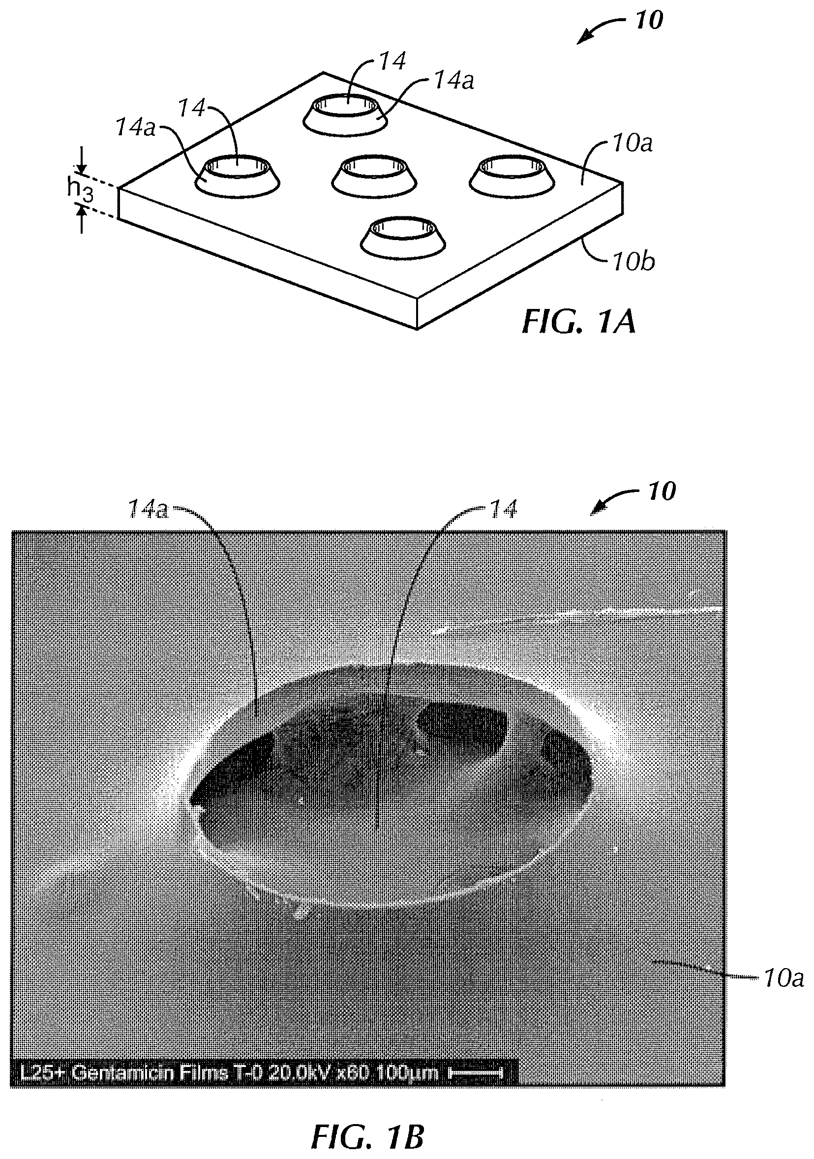
FIG. 1A is an enlarged perspective schematic view of a portion of a film (in this instance a polymer film) in accordance with an exemplary embodiment of the present invention;
FIG. 1B is a 60.times. magnified photo of an aperture of a polymer film in accordance with an exemplary embodiment of the present invention;
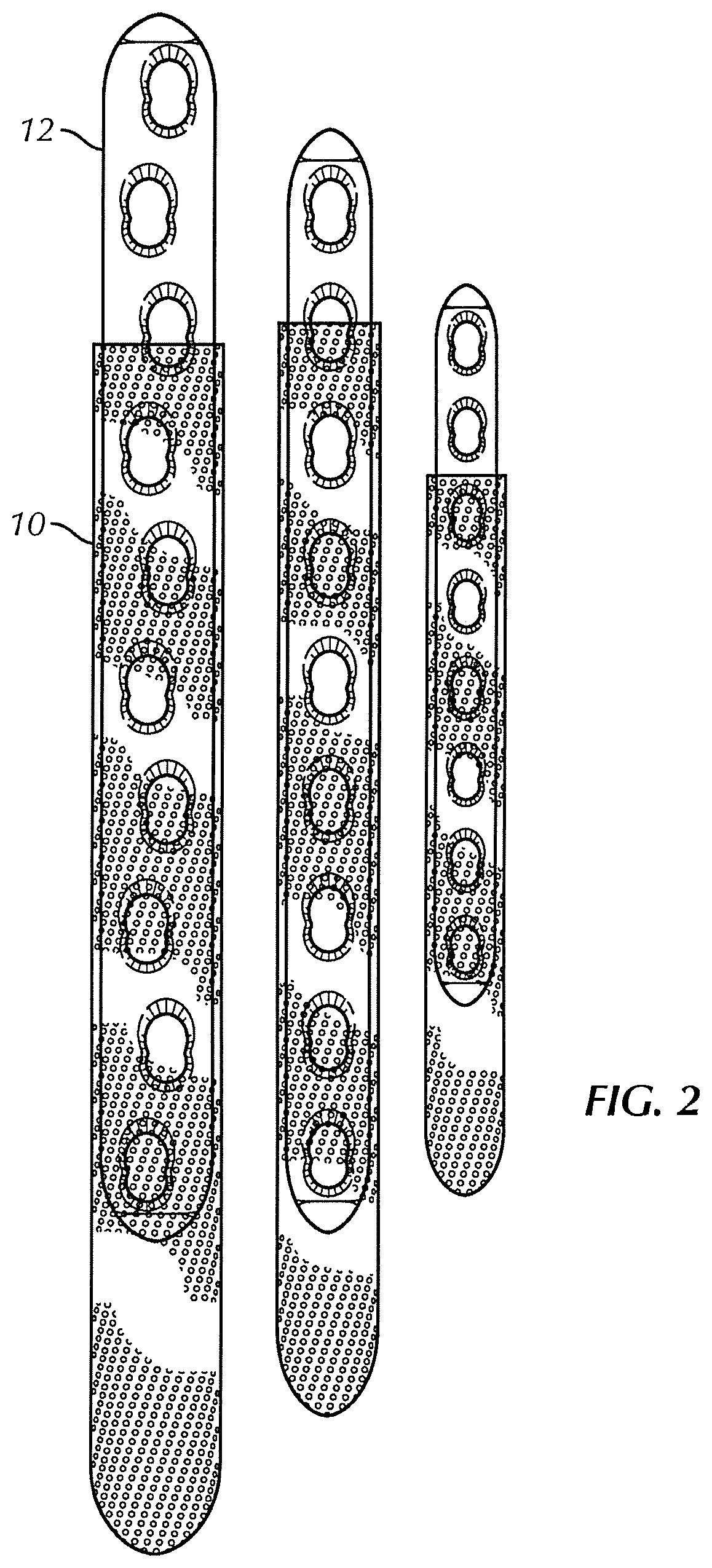
FIG. 2 is a top view of three exemplary sheaths formed from the polymer film of FIG. 1B in combination with a respective implantable medical device;
FIG. 3A is a perspective photograph of a portion of a mold in accordance with an exemplary embodiment of the present invention;
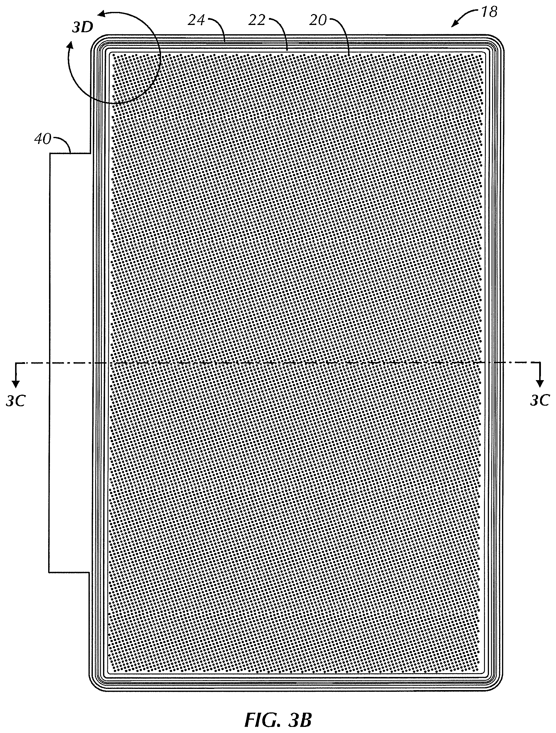
FIG. 3B is a top plan view of the mold of FIG. 3A;
FIG. 3C is a cross-sectional side view of the mold of FIG. 3B taken about line C-C in FIG. 3B;
FIG. 3D is an enlarged corner section of the mold shown in FIG. 3B;
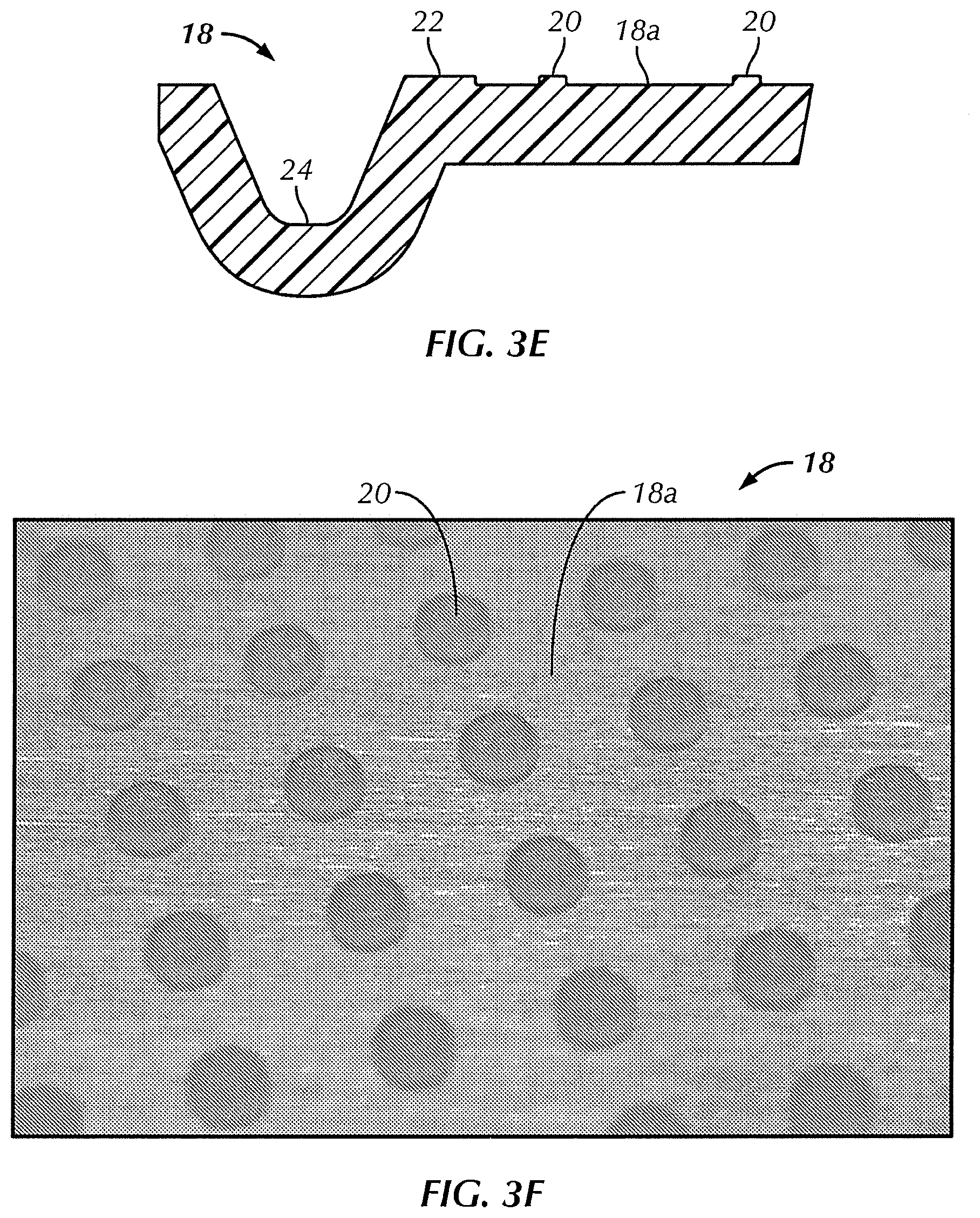
FIG. 3E is an enlarged cross section of the mold shown in FIG. 3D taken along line B-B;
FIG. 3F is an enlarged perspective photograph of the mold of FIG. 3A;
FIG. 3G is an enlarged perspective photograph of a mold in accordance with another exemplary embodiment of the present invention;
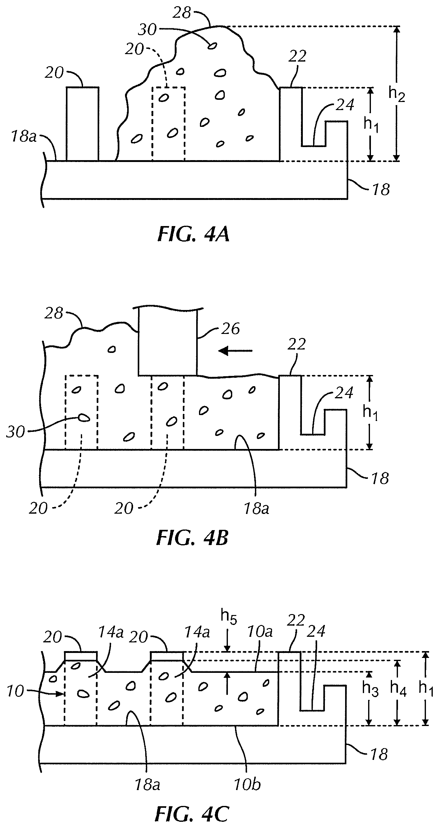
FIG. 4A is a schematic side cross-sectional view of the mold of FIG. 3A with the polymer added;
FIG. 4B is a schematic side cross-sectional view of the mold shown in FIG. 4A showing the drawing device drawing the polymer across the mold;
FIG. 4C is a schematic side cross-sectional view of the mold shown in FIG. 4A showing the polymer after being drawn across the mold and solidified to form a polymer film;
FIG. 5 is a perspective view of an automated casting apparatus in accordance with an exemplary embodiment of the present invention;
FIG. 6 is a perspective view of the automated casting apparatus of FIG. 5 showing the polymer being added to the mold;
FIG. 7 is a perspective view of the automated casting apparatus of FIG. 5 showing the drawing device drawing the polymer across the mold;
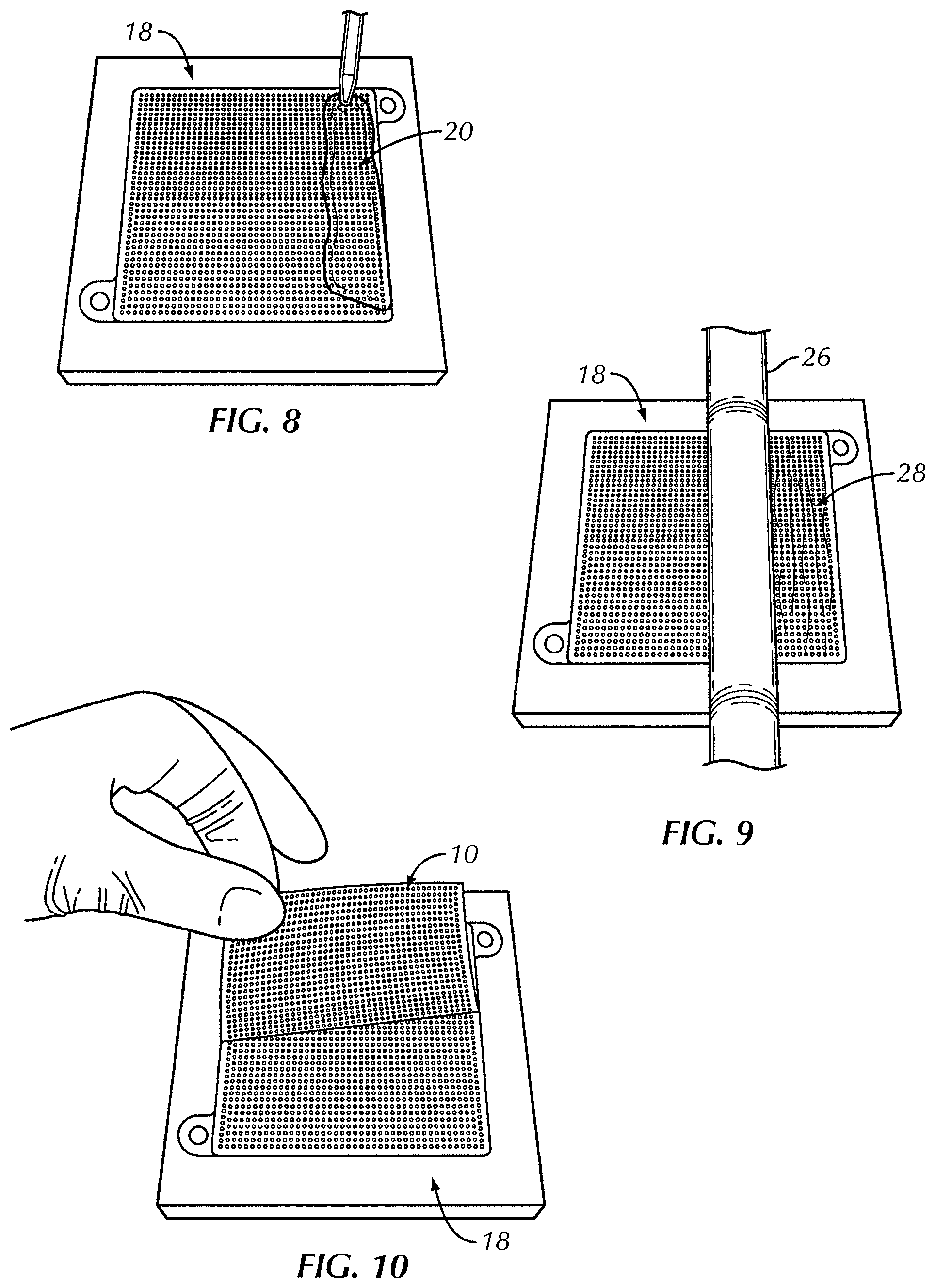
FIG. 8 is a perspective view of polymer being added to a mold in accordance with another exemplary embodiment of the present invention;
FIG. 9 is a perspective view of the mold of FIG. 8 showing the drawing device drawing the polymer across the mold;
FIG. 10 is a perspective view of the mold of FIG. 8 showing the polymer film being removed from the mold;
FIG. 11A is a top plan view of a sheath formed using the polymer film of FIG. 1 shown in a first configuration;
FIG. 11B is a top plan view of a sheath formed using the polymer film of FIG. 1 shown in a second configuration;
FIG. 11C is a top plan view of a sheath formed using the polymer film of FIG. 1 shown in a third configuration;
FIG. 11D is a top plan view of a sheath formed using the polymer film of FIG. 1 shown in a fourth configuration;
FIG. 11E is the area within circle B in FIG. 11D;
FIG. 11F is an enlarged view of a seam of a sheath such as those shown in FIGS. 11A-11D;
FIG. 12 is a yield stress graph of a polymer film in accordance with an exemplary embodiment of the present invention;
FIG. 13 is a strain at yield graph of a polymer film in accordance with an exemplary embodiment of the present invention;
FIG. 14 is a graph illustrating the rate of drug release over time when a sleeve in accordance with an exemplary embodiment of the present invention is placed into saline solution;
FIG. 15 is an in-vitro mass loss graph of a polymer film in accordance with an exemplary embodiment of the present invention; and
FIG. 16 is an in-vitro molecular weight loss graph of a polymer film in accordance with an exemplary embodiment of the present invention.
DETAILED DESCRIPTION OF THE INVENTION
Infections represent a major challenge in orthopedic or trauma surgery. Despite prophylactic measures like asepsis and antisepsis, the surgery site is still a site of access for local pathogens to become virulent and cause infections.
Coating an implantable device with a drug such as an antibiotic, has been effective to reduce infection. However, given the large number, sizes, and shapes of implants and other medical devices, the regulatory, financial, and logistical burden of providing a coating for each device is enormous. The problem is amplified if one considers additional drugs to use in coatings such as analgesics, antineoplastic agents and growth promoting substances.
Embodiments of the present invention are directed to improved perforated polymer films and novel casting methods of making the same. In some embodiments, the films are for use with implantable medical devices though the films may be used in any application.
Commercial methods of forming a perforated film currently existing generally involve forming a solid film as a first step, then punching or cutting holes into the film as a second step. An advantage of at least some of the embodiments described herein is that the holes or perforations of the film are formed at the same time that the film is formed. This may be useful when the polymer film formed is very thin and at risk for damage due to subsequent handling or processing or when the thickness and/or strength of the film makes it difficult to punch or cut by traditional methods without damaging the film. Such a process may also be advantageous when the polymer solution contains a drug or other active that may be damaged by subsequent cutting or punching steps.
Embodiments of the present invention may also be useful for making quantities of cast film such as those which are considered too small to make economically by traditional methods which are typically continuous processes designed for high volume production. An additional advantage of at least some embodiments of the invention is that perforations formed in the cast sheet can have complex shapes. A further advantage of at least some of the embodiments of the invention is that at least one side of the film may be formed to have a non-planar surface which in some embodiments increases friction and gives an improved tactile feel. These advantages of the present invention, as well as others, are described in further detail below.
Referring to the drawings in detail, wherein like reference numerals indicate like elements throughout, there is shown in FIGS. 1A and 1B polymer films, generally designated 10, and molds, generally designated 18, in accordance with exemplary embodiments of the present invention.
Referring to the embodiment of FIG. 1A, film 10 (e.g., a polymer film) is a flexible body having a first surface 10a and an opposing second surface 10b.
In one embodiment, film 10 may be formed from a single thin sheet of a biologically-compatible material. In one embodiment, film 10 is comprised of two or more sheets of material. In a preferred embodiment, the biologically-compatible material is bioresorbable. In embodiments used with a medical (see FIG. 2), film 10, in some embodiments, will dissolve away over time when implanted in vive and be absorbed into a patient, leaving only medical device 12 behind (such as if medical device 12 is not also made of a bioresorbable material). Medical device 12 may also be made of a bioresorbable material in other embodiments in which case both medical device 12 and film 10 will eventually dissolve. In some embodiments, film 10 may be configured to absorb at a different rate from an absorbable medical device 12 (e.g., a faster or a slower rate).
In some embodiments, a bioresorbable film 10 has advantages over non-resorbable meshes which, for example, can become encased with or embedded in dense fibrous tissue or present other issues associated with long term foreign body exposure. In some embodiments, film 10 is only partially bioresorbable.
A bioabsorbable polymer may be used in order to provide a controlled release of a drug such as an antibiotic, with a definite end point. Continuous, long term presence of an antibiotic is often undesirable, since this can create conditions for development of antibiotic resistant bacteria. In one embodiment, complete degradation of film 10 ensures that the drug will be completely released in a pre-determined and/or selectable time. In one embodiment, the drug release can be completely released or substantially completely released even where the film 10 is not fully absorbed.
The absorption of film 10 may also impact and/or control the release of the antibiotic in the continuous release phase. As the film degrades, for example, the permeability of the film may increase, and more drug may be released. In some embodiments, the polymer used must be for a structure that is flexible, have relatively high tensile strength, and be able to be processed by solution casting. In one embodiment, film 10 is comprised of a co-polymer that includes one or more of four monomers; glycolide, lactide, caprolactone, and trimethylene carbonate. Glycolide may be included and may have the effect of speeding up degradation of film 10. Lactide may also be included and may have the effect of increasing mechanical strength of film 10. Caprolactone and trimethylene carbonate may be used and may have the effect of increasing flexibility of film 10.
In one embodiment, the bioresorbable polymer includes one or more of PLA, PGA, polycaprolactone, polydioxanone, TMC and copolymers of these. In one embodiment, the bioresorbable polymer is produced from a copolymer of glycolic acid, caprolactone lactic acid, and trimethylene carbonate. In one embodiment, the bioresorbable polymer is produced from a copolymer of approximately 60% glycolic acid, approximately 20% caprolatone, approximately 10% lactic acid and approximately 10% trimethylene carbonate. In one embodiment, the bioresorbable polymer contains repeat units selected from the group consisting of: L-lactic acid, D-lactic acid, L-lactide, D-lactide, D,L-lactide, glycolide, a lactone, a lactam, trimethylene carbonate, a cyclic carbonate, a cyclic ether, para-dioxanone, beta-hydroxybutyric acid, beta-hydroxypropionic acid, beta-hydroxyvaleric acid, and a combination thereof. In one embodiment, the bioresorbable polymer contains repeat units selected from the group consisting of: L-lactic acid, D-lactic acid, L-lactide; D-lactide, D,L-lactide, .epsilon.-caprolactone, trimethylene carbonate, para-dioxanone, and a combination thereof. In one embodiment, the bioresorbable polymer is a copolymer of glycolide, trimethylene carbonate, lactide and caprolactone. Film 10 may also or alternatively include natural biopolymers such as alginate, chitosan, collagen, gelatin, hyaluronate, zein and others.
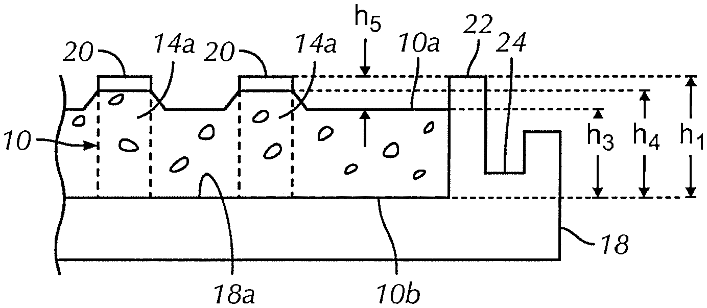
Still referring to FIG. 1A, film 10 may be configured to have any preferred dimensions including thickness h.sub.3 measured between first surface 10a and second surface 10b not inclusive of the raised lips 14a that are illustrated in FIGS. 1A and 1B as surrounding apertures 14. In one embodiment, film 10 must be thin enough such that it does not interfere with the mechanical interlocking between a plate 12 and the screws used in fixation (such as where if the film is trapped between the plate and screw). In some embodiments, thickness h.sub.3 is minimized as much as possible. In one embodiment, the thickness of film 10 is selected such that degradation of film 10 does not cause significant loosening of a connection to medical device 12 such as a plate-screw construct.
In some embodiments, thickness h.sub.3 of film 10 is approximately 0.05 mm. In some embodiments, thickness h.sub.3 of film 10 is approximately no greater than 0.05 mm. In some embodiments, thickness h.sub.3 of film 10 is less than approximately 0.05 mm. In some embodiments, thickness h.sub.3 of film 10 is approximately 0.06 mm. In some embodiments, thickness h.sub.3 of film 10 is approximately 0.07 mm. In some embodiments, thickness h.sub.3 of film 10 is approximately 0.08 mm. In some embodiments, thickness h.sub.3 of film 10 is approximately 0.09 mm. In some embodiments, thickness h.sub.3 of film 10 is approximately 0.1 mm. In some embodiments, thickness h.sub.3 of film 10 is approximately 0.2 mm. In some embodiments, thickness h.sub.3 of film 10 is approximately 0.3 mm. In some embodiments, thickness h.sub.3 of film 10 is approximately 0.4 mm. In some embodiments, thickness h.sub.3 of film 10 is approximately 0.5 mm.
In one embodiment, thickness h.sub.3 of film 10 is approximately uniform throughout film 10. In some embodiments, film 10 is tapered toward on or more edges along the outer periphery. In some embodiments, thickness h.sub.3 of film 10 differs in two or more sections to control strength or drug delivery of each area.
In some embodiments, film 10 must be of sufficient strength to withstand mechanical forces such as implantation, drilling and screw placement. In one embodiment, film 10 has a first tensile strength in a first planar direction and a second tensile strength in a second planar direction that is perpendicular to the first planar direction, where the first tensile strength is substantially equal to the second tensile strength. In one embodiment, film 10 has the strength characteristics as listed in tables 1-3 below.
TABLE-US-00001 TABLE 1 Film Specimen Length Width Thickness Tensile strain at Yield Sample Start Date label (mm) (mm) (mm) (Offset 0.2%) (%) 1 Jun. 2, 2009 Day 0 50.00 10.510 0.059 2.44051 9:02 AM Sample 1 2 Jun. 2, 2009 Day 0 50.00 11.160 0.063 3.43452 9:05 AM Sample 2 3 Jun. 2, 2009 Day 0 50.00 11.230 0.062 2.04468 9:07 AM Sample 3 4 Jun. 2, 2009 Day 0 50.00 10.740 0.057 2.81023 9:09 AM Sample 4 5 Jun. 2, 2009 Day 0 50.00 11.180 0.066 3.06678 9:13 AM Sample 5 6 Jun. 2, 2009 Day 0 50.00 10.920 0.058 3.65944 9:15 AM Sample 6 Mean 50.00 10.957 0.061 2.90936 Standard 0.000 0.288 0.003 0.607 Deviation Coefficient of 0.000 2.625 5.639 20.854 Variation
TABLE-US-00002 TABLE 2 Tensile stress at Tensile strain at Yield Tensile strain at Tensile stress at Break Film (Offset 0.2%) Maximum Load Maximum Load (Standard) Sample (MPa) (%) (MPa) (%) 1 13.75364 22.50031 26.31165 31.66499 2 14.00508 31.66468 27.57964 49.99874 3 9.25147 32.49843 26.60082 149.99967 4 12.82553 26.66562 28.46340 55.83280 5 13.53060 23.33406 26.59371 36.66562 6 12.60631 35.83187 26.79990 212.49840 Mean 12.66211 28.74916 27.05819 89.44337 Standard 1.756 5.393 0.812 74.322 Deviation Coefficient 13.865 18.760 3.000 83.094 of Variation
TABLE-US-00003 TABLE 3 Tensile stress at Break Modulus (Automatic Film (Standard) Young's) Sample (MPa) (MPa) 1 15.20147 749.15765 2 21.71590 504.50877 3 19.08817 657.83084 4 18.08469 574.31825 5 18.71550 618.69300 6 21.75346 436.82724 Mean 19.09320 590.22262 Standard 2.460 111.150 Deviation Coefficient 12.885 18.832 of Variation
In one embodiment, film 10 has a tensile strain at yield (Offset 0.2%) of approximately 2% to approximately 4% and/or a mean tensile strain of approximately 3%. In one embodiment, film 10 has a tensile stress at yield (Offset 0.2%) of approximately 9 MPa to approximately 14 MPa, and/or a mean tensile stress at yield of approximately 12.5 MPa. In one embodiment, film 10 has a tensile stress at maximum load of approximately 25 MPa to approximately 30 MPa, and/or a mean tensile stress at maximum load of approximately 27 MPa. In one embodiment, film 10 has a tensile strain at break (standard) of approximately 30% to approximately 215%, and/or a mean tensile strain at break of approximately 89%. In one embodiment, film 10 has an automatic Young's modulus of approximately 430 MPa to approximately 750 MPa, and/or a mean automatic Young's modulus of approximately 590 MPa. Film 10 may be characterized by combination of one or more of the foregoing properties.
Referring to FIGS. 1A, 1B, 2 and 11E, in some embodiments, film 10 includes a plurality of perforations or apertures 14. In one embodiment, apertures 14 allow the passage or transport of fluids through film 10 (e.g., when implanted near living tissue). In some embodiments, it may be important to allow for fluid flow from one side of the sleeve to the other (inside to outside) in order, for example, to avoid creating a "dead space" between film 10 and medical device 12. Additionally, perforations 14 may advantageously provide more even distribution of the drug or biological agent to adjacent tissue and bone as the material leaches out of the polymer than a sleeve without such perforations.
Apertures 14 may be configured to be any size and shape. In one embodiment, apertures 14 are defined by substantially cylindrical sidewalls. In some embodiments, apertures 14 have sidewalls that have segments that are inwardly facing convex surfaces. In some embodiments, the inwardly facing convex surface is substantially parabolic. Apertures 14 need not be perfectly round in cross section, and in some embodiments, may be ovoid, elliptical, star or diamond in shape. In some embodiments, apertures 14 extend to one or more apexes. In one embodiment, such apexes promote tears in film 10 during use (e.g., where a zone of weakness is created by the aperture). In one embodiment, apertures 14 extend completely through sheet 12 from an inside surface 10b to an outside surface 10a (see FIG. 4C). In one embodiment, one or more apertures 14 extend only partially through film 10 to control drug release or increase the initial strength of film 10.
Apertures 14 may be configured to allow for any desired porosity of film 10. In one embodiment, the porosity of film 10 is greater than approximately 0.01. In one embodiment, the porosity of film 10 is greater than approximately 0.02. In one embodiment, the porosity of film 10 is greater than approximately 0.03. In one embodiment, the porosity of film 10 is greater than approximately 0.04. In one embodiment, the porosity of film 10 is greater than approximately 0.05. In one embodiment, the porosity of film 10 is greater than approximately 0.06. In one embodiment, the porosity of film 10 is greater than approximately 0.07. In one embodiment, the porosity of film 10 is greater than approximately 0.08. In one embodiment, the porosity of film 10 is greater than approximately 0.09. In one embodiment, the porosity of film 10 is greater than approximately 0.10. In one embodiment, the porosity of film 10 is greater than approximately 0.11. In one embodiment, the porosity of film 10 is greater than approximately 0.12. In one embodiment, the porosity of film 10 is greater than approximately 0.13. In one embodiment, the porosity of film 10 is greater than approximately 0.15. In one embodiment, the porosity of film 10 is greater than approximately 0.15. In one embodiment, the porosity of film 10 is greater than approximately 0.16. In one embodiment, the porosity of film 10 is greater than approximately 0.17. In one embodiment, the porosity of film 10 is greater than approximately 0.18. In one embodiment, the porosity of film 10 is greater than approximately 0.19. In one embodiment, the porosity of film 10 is greater than approximately 0.20.
Referring to FIG. 11E, in one embodiment, apertures 14 have a diameter of approximately 0.75 mm and are spaced apart approximately 1.75 mm. In one embodiment, apertures 14 are arranged in a regular array (e.g., aligned rows and columns as illustrated in FIG. 11D). In one embodiment, apertures 14 are arranged in an irregular array.
Referring to FIGS. 1A, 1B and 4C, in some embodiments, each aperture 14 is proximate to at least one raised lip 14a protruding from the first surface 10a. A benefit of the raised lip 14a around each perforation 14 may include providing a reinforcement or grommet to each perforation 14, effectively increasing the mechanical strength of film 10 relative to a similar perforated film with no raised lips 14a. A benefit of lips 14a may include a textured surface on first surface 10a. Such a texture may be an advantage for tactile feel or for the purpose of increasing (or reducing) friction of first surface 10a of film 10 when, for example, first surface 10a is in contact with another surface. In one embodiment, lip 14a decreases the tendency of the film 10 to adhere to a surface such as the metal surface of an implant, making it easier to slide a sleeve made from the film 10 onto the implant. In one embodiment, lips 14a act as stand-offs between the implant and film 10 reducing the surface area of film 10 that is in contact with the implant.
In one embodiment, first surface 10a includes a contiguous planar portion extending between the plurality of raised protruding lips 14a. In one embodiment, lip 14a is substantially in the shape of the outer surface of an impact crater. In one embodiment, lip 14a includes a continuous concave surface. In one embodiment, lip 14a includes a parabolic concave surface. In one embodiment, one or more of lips 14a (or, in some embodiments, each lip 14a) has a conave outer surface and an convex opposing inner surface, either or both of which are parabolic in shape. In one embodiment, lips 14a each have an edge that is raised above the contiguous planar portion of first surface 10a by approximately 0.1 mm to approximately 1.0 mm. In one embodiment, lips 14a each have an edge that is raised above the contiguous planar portion of first surface 10a by approximately 0.1 mm. In one embodiment, lips 14a each have an edge that is raised above the contiguous planar portion of first surface 10a by approximately 0.2 mm. In one embodiment, lips 14a each have an edge that is raised above the contiguous planar portion of first surface 10a by approximately 0.3 mm. In one embodiment, lips 14a each have an edge that is raised above the contiguous planar portion of first surface 10a by approximately 0.4 mm. In one embodiment, lips 14a each have an edge that is raised above the contiguous planar portion of first surface 10a by approximately 0.5 mm. In one embodiment, lips 14a each have an edge that is raised above the contiguous planar portion of first surface 10a by approximately 0.6 mm. In one embodiment, lips 14a each have an edge that is raised above the contiguous planar portion of first surface 10a by approximately 0.7 mm. In one embodiment, lips 14a each have an edge that is raised above the contiguous planar portion of first surface 10a by approximately 0.8 mm. In one embodiment, lips 14a each have an edge that is raised above the contiguous planar portion of first surface 10a by approximately 0.9 mm. In one embodiment, lips 14a each have an edge that is raised above the contiguous planar portion of first surface 10a by approximately 1.0 mm.
In one embodiment, due to lips 14a, first surface 10a has a first tactile feel that is different (e.g., distinguishable by a surgeon wearing a surgical glove) from a second tactile feel of second surface 10b without lips 14a. In one embodiment, apertures 14 in one or more areas on first surface 10a each are bounded by a raised lip 14a and apertures 14 in one or more other areas on first surface 10a are not so bounded. In one embodiment, height h.sub.4 (see FIG. 4C) of each raised lip 14a is uniform. In one embodiment, at least one raised lip 14a has a different height h.sub.4 than at least one other lip 14a. In one embodiment, one or more apertures 14 are bounded by a lip 14a on one or both first surface 10a and second surface 10b. An embodiment such as the one illustrated in FIG. 1A, may include a single continuous lip 14a that surrounds each aperture 14. The continuous lip may be substantially uniform in thickness and/or substantially uniform in height relative to any one aperture, or from aperture to aperture. Apertures 14 may be evenly spaced apart across all or at least a portion of the polymer sheet. In other embodiments, at least a portion of the polymer sheet is characterized by apertures that are spaced apart in at least two different spacing configurations.
In some embodiments, film 10 includes one or more drugs or other substance for delivery in the body. Such drugs include, but are not limited to, antimicrobial agents, anti-fibrotic agents, anesthetics and anti-inflammatory agents as well as other classes of drugs, including biological agents such as proteins, growth inhibitors and the like.
In one embodiment, film 10 includes an antibiotic. The antibiotic selected may be active against the majority of bacteria found in orthopedic implant related infections. These include primarily staphylococci, and Gram negative bacilli.
In one embodiment, the drug selected must be stable during the manufacturing processes required to fabricate the implant. In one embodiment, film 10 includes gentamicin. Gentamicin sulfate is thermally stable above 100.degree. C., and is stable to organic solvents including DMSO, which is used in the manufacturing process in some embodiments.
Referring to FIGS. 4A-4C, in one embodiment, film 10 comprises a plurality of discrete eluting drug components 30. In one embodiment, film 10 is configured to elute the plurality of discrete drug components 30 at different time periods following implantation. In one embodiment, the elution of gentamicin in vive is a two-phase process, with a burst release occurring as soon as film 10 contacts water or body fluid, and a second phase which is controlled by the degradation rate of the polymer. In some embodiments, it is desirable to have an initial burst release of gentamicin to reduce bacterial contamination of the wound site on initial implantation, then a lower level release of gentamicin for a period of days to weeks afterward, to prevent growth of any surviving bacteria. In one embodiment, film 10 is configured to elute up to approximately 60 percent of the drug contained within film 10 approximately 1 week after film 10 has been implanted in contact with living tissue. In one embodiment, the combination of particle size and polymer degradation rate control the drug release profile, and create the desired 2-phase release. In one embodiment, the drug is released over a 2 to 3 week time period. In other embodiments, the drug is released over a shorter or longer time frame.
In one embodiment, the relative amounts of drug released during these two phases are controlled by the particle size. In one embodiment, drug components 30 are evenly distributed throughout film 10, and any drug components 30 in contact with a surface of film 10 are dissolved more rapidly than a drug component 30 that is not in contact with a surface of film 10. In one embodiment, a quantity of drug components 30 that are in contact with a surface of film 10 upon implantation are configured to release in a burst upon implantation. In one embodiment, the larger the size of drug components 30, the higher the proportion of drug components 30 in contact with the surface, and the greater the burst release. For this reason, the size of drug components 30, in one embodiment, is kept under 10 microns in diameter which reduces the burst release to approximately 20 to 35% of the total drug content. In one embodiment, drug components 30 are under 20 microns in diameter.
In one embodiment, film 10 is configured to deliver multiple drugs from one or more independent layers, some of which may contain no drug. In another embodiment, film 10 may include a plurality of drug components each being characterized by a different release rate from film 10 such that a first drug is associated with a first release profile that is different from a second release profile of a second drug.
Referring to FIGS. 3A-11F, there are shown devices used in a method of manufacturing films 10 in accordance with exemplary embodiments of the present invention.
In one embodiment, the manufacturing method of polymer films 10 was developed to make polymer films 10 for use as drug delivery membranes. In one embodiment, film 10 is solvent cast. In some embodiments, solvent casting methods are advantageous in the fabrication of films 10 that contain a drug component 30 that could be potentially damaged by the heat and shear of melt processes such as blown film extrusion. Producing films using a punch press (e.g., with many hundreds or thousands of holes or holes with complicated geometry) may also be time consuming and expensive. In some embodiments, a solvent and drug 30 are first mixed to form a well distributed suspension then polymer is added into the solution.
In some embodiments, methods described here allow for formation of the thin films 10 and formation of apertures 14 in a single step. In some embodiments, methods described herein allow for a film 10 with thousands of apertures 14 with accurate control of geometry and placement and accurate control of film thickness.
Referring to FIGS. 3A-3G, in some embodiments, film 10 is cast using mold 18. In one embodiment, mold 18 includes a plurality of protrusions or posts 20 extending from a bottom 18a of mold 18 to form apertures 14. In one embodiment, mold 18 is comprised of injection molded polypropylene. The mold may be manufactured from other materials, including polymers (see FIG. 3F), glass, metals (see FIG. 30) or ceramics. In one embodiment, mold 18 is comprised of two or more materials. For example, mold 18 may have a base made from metal with a polymer coating to reduce adhesion of the cast film to the mold and/or to form posts 20. The cavity in the mold may be formed by a casting process, a compressing molding process, an injection molding process, a chemical etching process or a machining process.
In one embodiment, mold 18 includes a cavity depth of approximately 0.25 mm. In one embodiment, a distance from the bottom of the mold 18a to a top of each of the plurality of posts 20 is equal to the cavity depth (i.e., the height of peripheral wall 22) or vice versa. In one embodiment, posts 20 are longer than the desired thickness of film 10. In one embodiment, posts 20 extend 0.3 mm from the bottom of mold 18a. In one embodiment, posts 20 extend 0.2 mm from the bottom of mold 18a. In one embodiment, posts 20 extend 0.25 mm from the bottom of mold 18a. In one embodiment, posts 20 extend 0.3 mm from the bottom of mold 18a. In one embodiment, posts 20 extend 0.35 mm from the bottom of mold 18a. In one embodiment, posts 20 extend 0.4 mm from the bottom of mold 18a. In one embodiment, posts 20 extend 0.45 mm from the bottom of mold 18a. In one embodiment, posts 20 extend 0.5 mm from the bottom of mold 18a.
In one embodiment, posts 20 are arranged to produce the selected size, shape, pattern, and arrangement of apertures 14 described above. In one embodiment, a perimeter form or peripheral wall 22 defines a total mold area, and the plurality of posts 20 define an area that is substantially equal to or corresponding to the open pore area of film 10.
In one embodiment, mold 18 includes a trough 24 that extends at least partially around peripheral wall 22 of mold 18. In one embodiment, trough 24 extends around the entire peripheral wall 22 of mold 18. In some embodiments, trough 24 retains any excess polymer that flows or is urged over peripheral wall 22. In one embodiment, mold 18 includes an extension 40 extending laterally from at least one outer edge of mold 18. In one embodiment, extension 40 is provided for grasping and manipulating mold 18 without contacting the polymer solution within mold 18.
In one embodiment, a polymer solution 28 for adding to mold 18 is formed. In one embodiment, a polymer material is dissolved at a 4:1 solvent to polymer ration in dimethyl sulfoxide (DMSO) at elevated temperature and the drug gentamicin sulfate is added at 13% by weight. In one embodiment, polymer solution 28 is formed by introducing drug units 30 to a polymer/solvent blend at a temperature below 90.degree. C. In one embodiment, polymer solution 28 comprises a cross-linkable pre-polymer such as polyurethanes, polyfumarates, polymethacrylates, etc.
Referring to FIGS. 4A, 6 and 8, once the polymer solution 28 is prepared, polymer solution 28 is placed into a one sided mold 18. In some embodiments, the viscosity of polymer solution 28 and/or the density of posts 20 substantially inhibits the unaided flow of the polymer 28 throughout mold 18. In one embodiment, after adding polymer solution 28 to mold 18, the top surface of polymer solution 28 is a height h.sub.2 above the base 18a of mold 18 which is greater than a height h.sub.1 of the mold cavity and posts 20.
Referring to FIGS. 4B, 7 and 9, after adding polymer solution 28 to mold 18, in one embodiment, an urging means 26 is used to urge the polymer solution around each of the plurality of posts 20. In one embodiment, urging means 26 includes a blade, bar, squeegee or roller that is slide, or the mold 18 is moved relative to urging means 26, across perimeter form 22 and the tops of posts 20 to force polymer solution 28 to flow around posts 20 and throughout mold 18 such that polymer solution 28 has a substantially uniform thickness. In one embodiment, drawing urging means 26 across mold 18 removes excess material from the top surface of posts 20. In one embodiment, an outer surface of each post 20 is substantially free of polymer solution 28 after the drawing.
Referring to FIG. 4C, once polymer solution 28 is drawn or spread throughout mold 18, polymer solution 28 is solidified to form film 10. In one embodiment, mold 18 is placed into a solvent drying oven at an elevated temperature to remove the solvent, leaving behind a thin cast film. In one embodiment, polymer solution 28 is solidified by cross-linking the polymer by applying UV radiation, temperature change, polymerization catalysts, soluble crosslinking agents or combinations thereof to polymer solution 28. In one embodiment, the solidifying step includes exposing mold 18 containing polymer solution 28 to a second solvent. In one embodiment where, for example, polymer solution 28 includes polymer, a drug and a first solvent, the first solvent is soluble in the second solvent, but the polymer and drug component are not soluble in the second solvent. Thus, by exposing polymer solution 28 to the second solvent, the first solvent is removed from the polymer solution leaving the polymer and the drug product to solidify to form, for example, the film.
In one embodiment, solidifying the polymer solution reduces a thickness of the polymer solution from a thickness h.sub.1 to a thickness h.sub.3. In one embodiment, solidifying the polymer solution reduces a thickness of the polymer solution proximate posts 20 from a thickness h.sub.1 to a thickness h.sub.4. In one embodiment, thickness h.sub.4 of film 10 proximate posts 20 is greater than a thickness h.sub.1 of film 10 between posts 20. In one embodiment, lips 14a are formed by polymer solution forming a meniscus around each of posts 20 during solidifying of polymer solution 28 to film 10. In one embodiment, meniscus or lip 14a is approximately the same height h.sub.4 as height or depth h.sub.1 of the mold 18. In one embodiment, height h.sub.4 of lips 14a may be controlled by careful selection of the material and geometry of posts 20 or by coating posts 20 with, for example, a lubricious material such as a fluoropolymer or silicone mold release. In one embodiment, height h.sub.4 of lips 14a is controlled by the concentration of the polymer solution.
Referring to FIG. 10, once polymer solution 28 is solidified, mold 18 and film are removed from the oven, allowed to cool, and the cast perforated film 10 is peeled out of mold 18.
Referring to FIGS. 5-7, a method of producing film 10 may include an automated or partially automated casting machine 42. In one embodiment, the automated casting apparatus includes one or more computers 44 having one or more processors and memory (e.g., one or more nonvolatile storage devices). In some embodiments, memory or computer readable storage medium of memory stores programs, modules and data structures, or a subset thereof for a processor to control and run the various systems and methods disclosed herein. In one embodiment, a computer readable storage medium having stored thereon computer-executable instructions which, when executed by a processor, perform one or more of the methods disclosed herein.
Film 10 may be manufactured by alternative methods. In one embodiment, polymer solution 28 can be cast onto perforated film material with a backing blotter layer, then the perforated film is removed from the blotter layer, removing the cast solution where there were holes in the casting sheet. One difference with such a process from the above described processes is that, in some embodiments, it does not create a raised lip around apertures 14.
In another embodiment, porous films may also be formed by a lyophilazation or freeze-drying method. In one embodiment, a thin solid film of polymer solution is cast in a mold, then the mold chilled to a temperature below the freezing point of the solution, then placed under vacuum to remove the solvent from the film. In some embodiments, this process will also produce fine pores which are much smaller than those described in some of the embodiments above.
In one embodiment, the polymer material used to form the cast film could be a crosslinkable prepolymer liquid, which is cast into the film mold as described, squeegeed to fill the mold and remove excess material, then crosslinked in place by UV radiation, temperature, a catalyst or other means. In one embodiment, this process could produce a very similar final product as described above, except that the final thickness of the cast film would be close to or the same as the depth of the mold, and there would be little or no meniscus or lip 14a around apertures 14.
In another embodiment, a thin porous film can be formed by a screen printing process. In one embodiment, a layer of solution is screen printed in the final pattern, then dried. In one embodiment, this produces a much thinner layer, however multiple layers of polymer can be screen printed and dried one on top of the other to build up the desired thickness of film.
In another embodiment, a similar casting process could be performed as described above using a glass plate with a pattern made from a hydrophobic polymer such as silicone, in the shape of the desired perforations. In one embodiment, when a thin layer of polymer solution is cast onto the plate, the surface tension differences between the glass and the patterned polymer cause the solution to concentrate on the glass surface, and pull away from the patterned hydrophobic polymer surface. In one embodiment, the solution is then dried to form a solid film with perforations in the same pattern as the silicone polymer. In one embodiment, this process could also be performed with a crosslinkable prepolymer liquid as described above.
In another embodiment, a thin porous polymer film is made using a two-sided mold, where the polymer solvent solution is injected into the mold, and chilled to solidify the solution. In one embodiment, the mold is then opened and one side removed, leaving the chilled solution in the cavity side. In one embodiment, the chilled solution side is placed into an oven to dry the polymer solution and form a film 10.
Referring to FIGS. 2 and 11A-11D, after creating film 10, film 10 is shaped and fashioned into a desired form. In one embodiment, film 10 is shaped and fashioned to generally match the size and shape of medical device 12. In some embodiments, film 10 is shaped and fashioned into a sheath or sleeve 32, 34, 36, 38.
Referring to FIGS. 11A-11F, sleeve 32, 34, 36, 38 includes at least one seam 16 configured to form film 10 into a sheath. In one embodiment, sleeve 32, 34, 36, 38 is formed by attached a first film 10 to a second film 10 around the outer periphery. In one embodiment, film 10 is folded and at least partially secured to itself. For example, film 10 may be shaped into a cylinder to adjoin two opposing edges. In one embodiment, second surface 10b is overlapped with first surface 10a to form seam 16. In one embodiment, second surface 10b is overlapped with second surface 10b to form seam 16. In one embodiment, seam 16 is secured by heating the overlapping portions of film 10 and allowing to re-solidify. In one embodiment, both ends of sleeve 32, 34, 36, 38 are left open for insertion of medical device 12. In one embodiment, one or more ends are closed. In one embodiment, polymer sheet is first to the desired size and shape before forming sleeve 32, 34, 36, 38.
In addition to sleeves 32, 34, 36, 38, film 10 may be used, in some embodiments, for other medical applications such as hernia repair mesh, adhesion barrier, soft tissue augmentation, filtration membranes, drug delivery membranes, bone graft containment (e.g., for maintaining bone graft in place for example in a spinal fusion procedure, or segmental defect grafting in a long bone), or wound care products such as bandages.
Example 1
In one exemplary embodiment, implants were tested by implantation in sheep. The implants were metal plates with tubular, thin (0.05-0.08 mm), transparent polymer sleeves carefully slipped over the metal plates just before they were surgically inserted and attached to the bone. The sleeves had a tight fit, covered the metal plates completely over the entire length, although they were open at both ends of the plates. The sleeves were comprised of a synthetic copolyester (glycolide, caprolactone, trimethylenecarbonate, lactide) with perforation holes of 1.5 mm diameter equally spaced throughout. One group of sleeves contained triclosan (2,4,4'-trichloro-2'-hydroxydiphenyl ether) at a concentration of 1%, one group of sleeves contained gentamicin at a concentration of 10%, and one group of sleeves contained a combination of both triclosan (1%) and gentamicin (10%). The concentration of gentamicin and Triclosan were chosen based on in vitro testing to determine the therapeutic window for each compound.
The hydrophobic triclosan was in complete solution within the polymer, in contrast to the hydrophilic gentamicin, which remained suspended as 10-20 .mu.m small particles. In vitro testing has shown that due to its poor water solubility, triclosan is released from these films only slowly over a to 3 weeks period, with minimal initial burst release.
Approximately 50% of the more water soluble gentamicin which is exposed to the surface of the sleeves was released into the adjacent tissue within 24 hours after insertion. The remaining gentamicin encapsulated in the depth of the polymer dissolves more slowly and was released over a 2 to 3 week period after implantation. The polymer was designed to degrade through hydrolysis within 60 days after surgery.
The sleeves with or without antimicrobial agents were proven biocompatible, with minimal effect on soft tissue and bone healing and not corrosive to the metallic implants. Additional details of the experiment can be found in Vet Surg. 2012 Jan. 12. Biodegradable Sleeves for Metal Implants to Prevent Implant-Associated Infection: An Experimental In Vivo Study in Sheep. Von Plocki S C, Armbruster D, Klein K, Kampf K, Zlinszky K, Hilbe M, Kronen P, Gruskin E, von Rechenberg B., which is hereby incorporated by reference in its entirety.
Example 2
In one exemplary embodiment, film 10 is manufactured by the following method:
Determination of Gentamicin Moisture Content:
The moisture content of gentamicin sulfate powder is measured by a loss on drying method. Approximately 0.5 grams of gentamicin is weighed in a glass jar, then heated under vacuum to 110.degree. C. for 3 hours and weighed a second time. The weight loss is recorded as the moisture content, which is used to calculate the percent moisture.
Solution Mixing:
14.69 grams of gentamicin sulfate powder is weighed, compensating for the percent moisture content as calculated above. This is mixed into 400 g of DMSO solvent in a 1 L vessel, using a paddle mixer. The mixture is stirred for 30 minutes until the gentamicin is uniformly distributed. 100 g of a copolymer containing glycolic acid, caprolactone, lactic acid, and trimethylene carbonate monomers is added to the suspension, and the mixing vessel is heated to 65.degree. C. Mixing is continued for 2 hours until the polymer is completely dissolved into the solution, then the solution temperature is reduced to 55.degree. C.
Film Casting & Solvent Drying:
A casting mold and drawing blade made from high density polyethylene are used to cast thin perforated films from the polymer solution. The casting mold and drawing blade are pre-cleaned using an alkaline detergent solution and loaded into an automated CNC casting fixture. 15 ml of the polymer solution are drawn up in a polypropylene syringe, which is loaded into the casting fixture. The casting fixture automatically dispenses the solution onto the casting mold, and draws the blade across the surface of the mold. The mold filled with polymer solution is placed into a solvent drying oven at 85.degree. C. for approximately 90 minutes to dry the film. The molds are removed from the drying oven and the films are peeled from the molds within 2 minutes.
Sleeve Sealing:
An impulse heat sealing press with specially shaped dies is used to seal and cut the cast film into the shape of a sleeve. Two cast films are placed into the press, and the press is closed with a pressure of 80 psi and heated to 200.degree. C. for 4 seconds. The sleeves are removed from the excess film material and cut to the appropriate length. Sealed sleeves can be dried under vacuum at 50.degree. C. and sealed in moisture barrier packaging to prevent degradation of the bioabsorbable polymer.
It will be appreciated by those skilled in the art that changes could be made to the exemplary embodiments shown and described above without departing from the broad inventive concept thereof. It is understood, therefore, that this invention is not limited to the exemplary embodiments shown and described, but it is intended to cover modifications within the spirit and scope of the present invention as defined by the claims. For example, specific features of the exemplary embodiments may or may not be part of the claimed invention and features of the disclosed embodiments may be combined. Unless specifically set forth herein, the terms "a", "an" and "the" are not limited to one element but instead should be read as meaning "at least one".
It is to be understood that at least some of the figures and descriptions of the invention have been simplified to focus on elements that are relevant for a clear understanding of the invention, while eliminating,
D00000
D00001
D00002
D00003
D00004
D00005
D00006
D00007
D00008
D00009
D00010
D00011
D00012
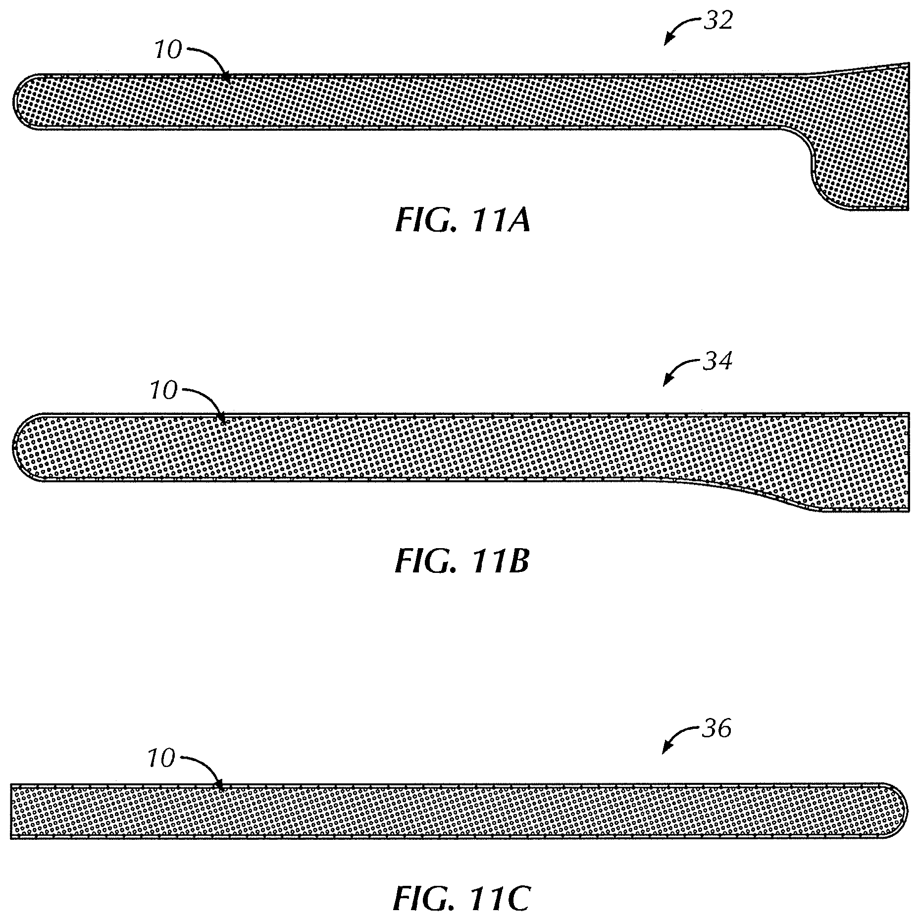
D00013
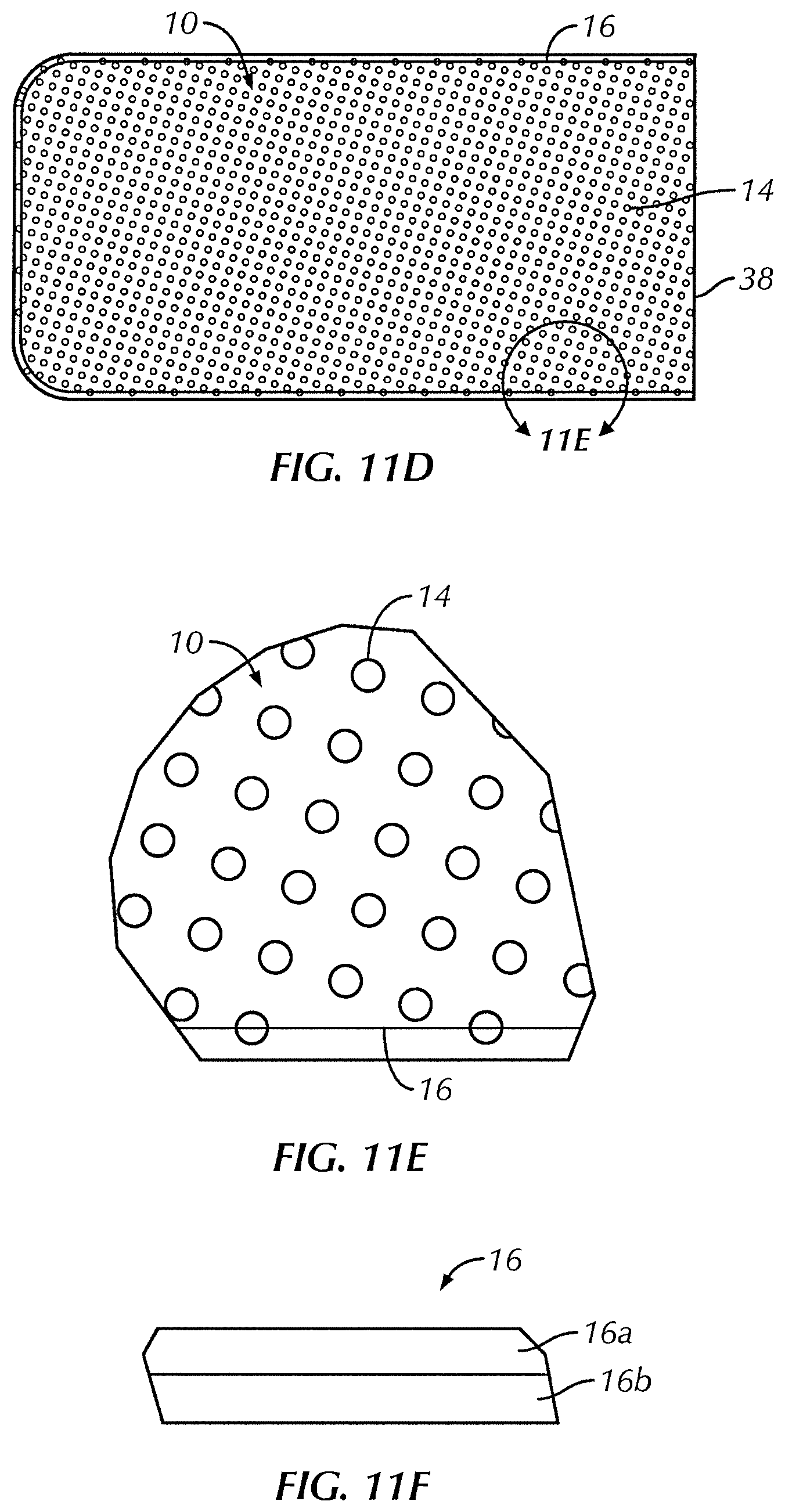
D00014

D00015
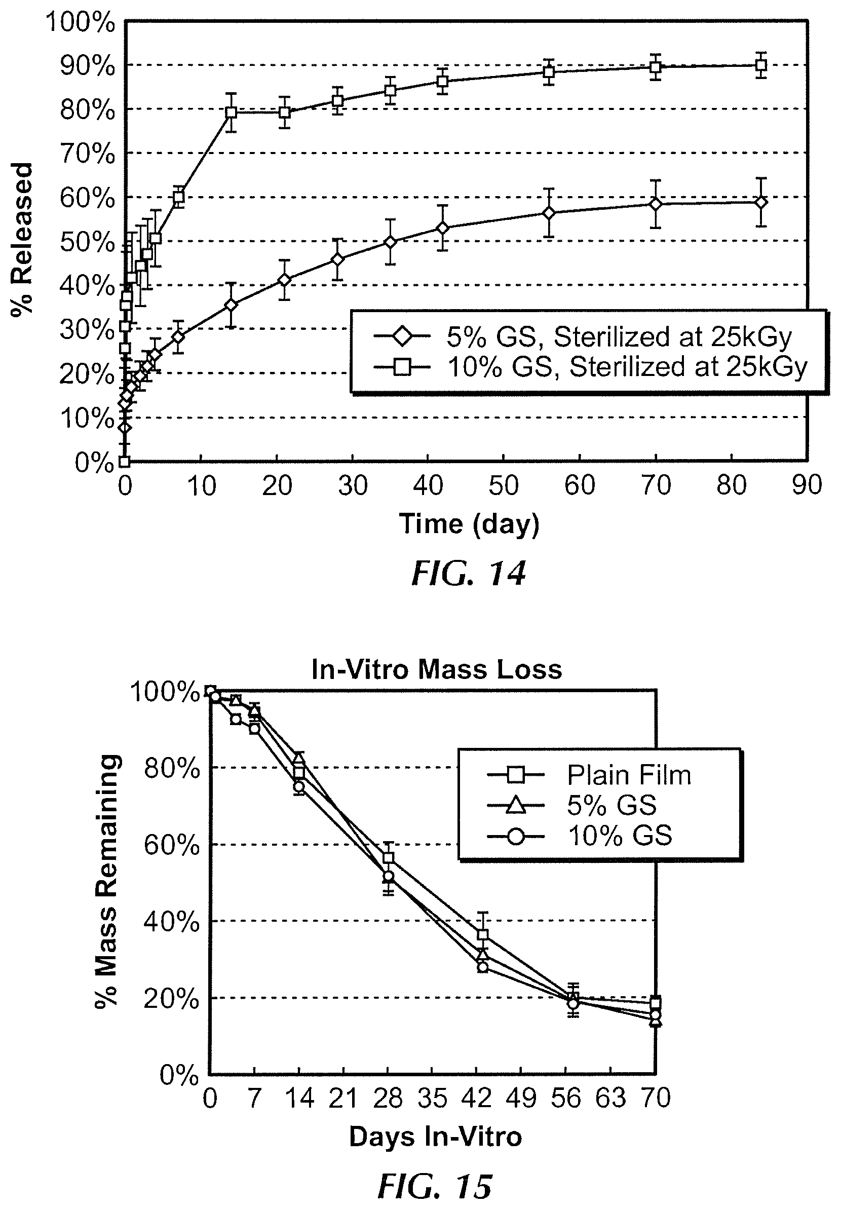
D00016
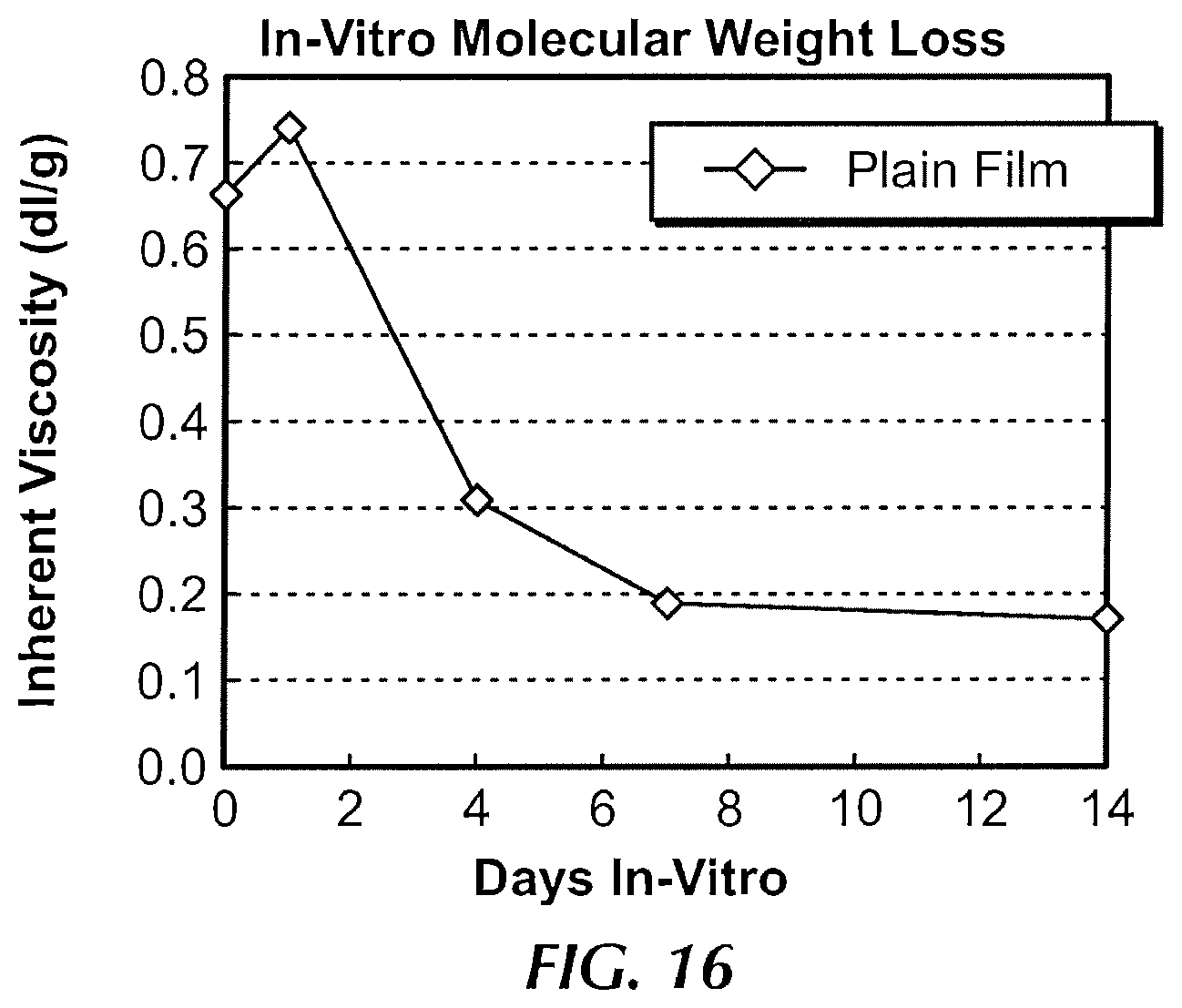
XML
uspto.report is an independent third-party trademark research tool that is not affiliated, endorsed, or sponsored by the United States Patent and Trademark Office (USPTO) or any other governmental organization. The information provided by uspto.report is based on publicly available data at the time of writing and is intended for informational purposes only.
While we strive to provide accurate and up-to-date information, we do not guarantee the accuracy, completeness, reliability, or suitability of the information displayed on this site. The use of this site is at your own risk. Any reliance you place on such information is therefore strictly at your own risk.
All official trademark data, including owner information, should be verified by visiting the official USPTO website at www.uspto.gov. This site is not intended to replace professional legal advice and should not be used as a substitute for consulting with a legal professional who is knowledgeable about trademark law.