Web adjuster
Eaton
U.S. patent number 10,611,334 [Application Number 15/890,239] was granted by the patent office on 2020-04-07 for web adjuster. This patent grant is currently assigned to Shield Restraint Systems, Inc.. The grantee listed for this patent is Shield Restraint Systems, Inc.. Invention is credited to James Russell Eaton.


| United States Patent | 10,611,334 |
| Eaton | April 7, 2020 |
Web adjuster
Abstract
Web adjusters and other web connecting devices for use with restraint systems are described herein. In some embodiments, web adjusters, such as tilt-lock web adjusters, can include web gripping features on an edge portion of a web aperture to prevent a web that is joined to the web adjuster from sliding or otherwise moving to one side of the web aperture or the other when the web is pulled in a direction that is not perpendicular to the edge. In some embodiments, the web gripping features can include alternating recessed and raised edge portions.
| Inventors: | Eaton; James Russell (Carmel, IN) | ||||||||||
|---|---|---|---|---|---|---|---|---|---|---|---|
| Applicant: |
|
||||||||||
| Assignee: | Shield Restraint Systems, Inc.
(Elkhart, IN) |
||||||||||
| Family ID: | 63039088 | ||||||||||
| Appl. No.: | 15/890,239 | ||||||||||
| Filed: | February 6, 2018 |
Prior Publication Data
| Document Identifier | Publication Date | |
|---|---|---|
| US 20180222439 A1 | Aug 9, 2018 | |
Related U.S. Patent Documents
| Application Number | Filing Date | Patent Number | Issue Date | ||
|---|---|---|---|---|---|
| 62455915 | Feb 7, 2017 | ||||
| Current U.S. Class: | 1/1 |
| Current CPC Class: | B60R 22/206 (20130101); B60R 22/30 (20130101); A44B 11/2557 (20130101); A44B 11/2549 (20130101); B60R 22/105 (20130101); B60N 2/2809 (20130101) |
| Current International Class: | B60R 22/20 (20060101); B60R 22/10 (20060101); B60R 22/30 (20060101); B60N 2/28 (20060101); A44B 11/25 (20060101) |
References Cited [Referenced By]
U.S. Patent Documents
| 906045 | December 1908 | Martin |
| 1079080 | November 1913 | Ward |
| 1369456 | February 1921 | Meredith |
| 1438898 | December 1922 | Carpmill |
| 1816262 | July 1931 | Ritter |
| 1930378 | October 1933 | Beagan |
| 2132556 | October 1938 | Blackshaw |
| 2255258 | September 1941 | Lethern et al. |
| 2372557 | March 1945 | Dowd |
| 2393178 | January 1946 | Manson |
| 2437585 | March 1948 | Zimmern |
| 2482693 | September 1949 | Rogers et al. |
| 2538641 | January 1951 | Elsner |
| 2549841 | April 1951 | Morrow et al. |
| 2639852 | May 1953 | Sanders et al. |
| 2641813 | June 1953 | Loxham |
| 2668997 | February 1954 | Irvin et al. |
| 2710999 | June 1955 | Davis |
| 2763451 | September 1956 | Moran |
| 2803864 | August 1957 | Bishaf |
| 2845233 | July 1958 | Pfankuch et al. |
| 2846745 | August 1958 | Lathrop |
| 2869200 | January 1959 | Phillips et al. |
| 2876516 | March 1959 | Cummings |
| 2892232 | June 1959 | Quilter |
| 2893088 | July 1959 | Harper et al. |
| 2899732 | August 1959 | Cushman |
| 2901794 | September 1959 | Prete, Jr. |
| 2921353 | January 1960 | Cushman |
| 2938254 | May 1960 | Gaylord |
| D188897 | September 1960 | Prete, Jr. |
| 2964815 | December 1960 | Sereno |
| 2965942 | December 1960 | Carter |
| 3029487 | April 1962 | Shinichiro |
| 3034596 | May 1962 | Twaits, Jr. |
| 3074760 | January 1963 | Hodgekin et al. |
| 3084411 | April 1963 | Lindblad |
| 3091010 | May 1963 | Davis |
| 3104440 | September 1963 | Davis |
| 3110071 | November 1963 | Higuchi |
| 3118208 | January 1964 | Wexler |
| 3132399 | May 1964 | Cooper |
| 3137907 | June 1964 | Unai |
| D198566 | July 1964 | Holmberg |
| 3142103 | July 1964 | Lindblad |
| 3142968 | August 1964 | Basham et al. |
| 3145442 | August 1964 | Brown |
| 3165805 | January 1965 | Lower |
| 3178226 | April 1965 | Cates |
| 3179992 | April 1965 | Murphy, Sr. |
| 3183568 | May 1965 | Gaylord |
| 3189963 | June 1965 | Warner et al. |
| 3218685 | November 1965 | Atumi |
| 3226791 | January 1966 | Carter |
| 3233941 | February 1966 | Selzer |
| 3256576 | June 1966 | Klove, Jr. et al. |
| 3262169 | July 1966 | Jantzen |
| 3287062 | November 1966 | Board et al. |
| 3289261 | December 1966 | Davis |
| 3293713 | December 1966 | Gaylord |
| 3306662 | February 1967 | Finnigan |
| 3312502 | April 1967 | Coe |
| 3323829 | June 1967 | Liem |
| 3369842 | February 1968 | Adams et al. |
| 3380776 | April 1968 | Dillender |
| 3414947 | December 1968 | Holmberg et al. |
| 3428029 | February 1969 | Klickstein et al. |
| 3451720 | June 1969 | Makinen |
| 3473201 | October 1969 | Hopka et al. |
| 3491414 | January 1970 | Stoffel |
| 3505711 | April 1970 | Carter |
| 3523342 | August 1970 | Spires |
| D218589 | September 1970 | Lohr |
| 3564672 | February 1971 | McIntyre |
| 3576056 | April 1971 | Barcus |
| 3591900 | July 1971 | Brown |
| 3605207 | September 1971 | Glauser et al. |
| 3605210 | September 1971 | Lohr |
| 3631571 | January 1972 | Stoffel |
| 3639948 | February 1972 | Sherman |
| 3644967 | February 1972 | Romanzi, Jr. et al. |
| 3648333 | March 1972 | Stoffel |
| 3658281 | April 1972 | Gaylord |
| 3673645 | July 1972 | Burleigh |
| 3678542 | July 1972 | Prete, Jr. |
| 3695696 | October 1972 | Lohr et al. |
| 3714684 | February 1973 | Gley |
| 3744102 | July 1973 | Gaylord |
| 3744103 | July 1973 | Gaylord |
| 3747167 | July 1973 | Pravaz |
| 3760464 | September 1973 | Higuchi |
| 3766611 | October 1973 | Gaylord |
| 3766612 | October 1973 | Hattori |
| 3775813 | December 1973 | Higuchi |
| 3825979 | July 1974 | Jakob |
| 3827716 | August 1974 | Vaughn et al. |
| 3856351 | December 1974 | Garvey |
| 3872550 | March 1975 | Yang |
| 3879810 | April 1975 | Prete, Jr. et al. |
| 3898715 | August 1975 | Balder |
| 3935618 | February 1976 | Fohl |
| 3964138 | June 1976 | Gaylord |
| 3975800 | August 1976 | Farlind |
| 3986234 | October 1976 | Frost et al. |
| 3995885 | December 1976 | Plesniarski |
| 4018399 | April 1977 | Rex |
| 4026245 | May 1977 | Arthur |
| 4051743 | October 1977 | Gaylord |
| 4095313 | June 1978 | Piljay et al. |
| D248618 | July 1978 | Anthony |
| 4100657 | July 1978 | Minolla |
| 4118833 | October 1978 | Knox et al. |
| 4128924 | December 1978 | Happel et al. |
| 4136422 | January 1979 | Ivanov et al. |
| 4148224 | April 1979 | Craig |
| 4181832 | January 1980 | Ueda |
| 4184234 | January 1980 | Anthony et al. |
| 4185363 | January 1980 | David |
| 4196500 | April 1980 | Happel et al. |
| 4220294 | September 1980 | Dipaola |
| 4228567 | October 1980 | Ikesue et al. |
| 4239260 | December 1980 | Hollowell |
| 4253623 | March 1981 | Steger et al. |
| 4262396 | April 1981 | Koike |
| 4273301 | June 1981 | Frankila |
| 4302049 | November 1981 | Simpson |
| 4317263 | March 1982 | Fohl |
| 4321734 | March 1982 | Gandelrnan |
| 4323204 | April 1982 | Takada |
| 4334341 | June 1982 | Krautz et al. |
| 4336636 | June 1982 | Ishiguro et al. |
| 4344588 | August 1982 | Hollowell et al. |
| 4366604 | January 1983 | Anthony et al. |
| 4385425 | May 1983 | Tanaka et al. |
| 4403376 | September 1983 | Palloks |
| 4408374 | October 1983 | Fohl |
| 4419874 | December 1983 | Brentini |
| 4425688 | January 1984 | Anthony et al. |
| 4428103 | January 1984 | Wier et al. |
| 4454634 | June 1984 | Haglund et al. |
| D274861 | July 1984 | Lindblad |
| 4457052 | July 1984 | Hauber |
| 4457251 | July 1984 | Weman et al. |
| 4487454 | December 1984 | Biller |
| 4491343 | January 1985 | Fohl |
| 4525901 | July 1985 | Krauss |
| 4545097 | October 1985 | Wier |
| 4549769 | October 1985 | Pilarski |
| 4555831 | December 1985 | Otzen et al. |
| 4562625 | January 1986 | Hunter, Jr. et al. |
| 4569535 | February 1986 | Haglund et al. |
| 4574911 | March 1986 | North et al. |
| 4587696 | May 1986 | Morinaga et al. |
| 4588208 | May 1986 | Yoshitsugu et al. |
| D285383 | September 1986 | Anthony |
| 4617705 | October 1986 | Anthony et al. |
| 4637099 | January 1987 | Kasai |
| 4637102 | January 1987 | Teder et al. |
| 4638533 | January 1987 | Gloomis et al. |
| 4640550 | February 1987 | Hakansson |
| 4644618 | February 1987 | Holmberg et al. |
| 4646400 | March 1987 | Tanaka |
| 4648483 | March 1987 | Skyba |
| 4650214 | March 1987 | Higbee |
| 4651946 | March 1987 | Anthony et al. |
| 4656700 | April 1987 | Tanaka et al. |
| 4660889 | April 1987 | Anthony et al. |
| 4679852 | July 1987 | Anthony et al. |
| 4682791 | July 1987 | Ernst |
| 4685176 | August 1987 | Burnside |
| 4692970 | September 1987 | Anthony et al. |
| 4711003 | December 1987 | Gelula |
| 4716630 | January 1988 | Skyba |
| 4720148 | January 1988 | Anthony et al. |
| 4726625 | February 1988 | Bougher |
| 4727628 | March 1988 | Rudholm |
| 4733444 | March 1988 | Takada |
| 4738485 | April 1988 | Rumpf |
| 4741574 | May 1988 | Weightman et al. |
| 4742604 | May 1988 | Mazelsky |
| D296678 | July 1988 | Lortz et al. |
| 4757579 | July 1988 | Nishino et al. |
| 4758048 | July 1988 | Shuman |
| 4766654 | August 1988 | Sugimoto |
| 4786078 | November 1988 | Schreier et al. |
| 4786080 | November 1988 | Jay |
| 4790597 | December 1988 | Bauer et al. |
| 4809409 | March 1989 | Van Riesen |
| 4832410 | May 1989 | Bougher |
| 4843688 | July 1989 | Ikeda |
| 4854607 | August 1989 | Mandracchia et al. |
| 4854608 | August 1989 | Barral |
| D303232 | September 1989 | Lortz et al. |
| 4876770 | October 1989 | Bougher |
| 4876772 | October 1989 | Anthony et al. |
| 4884652 | December 1989 | Vollmer |
| 4901407 | February 1990 | Pandola et al. |
| 4903377 | February 1990 | Doty |
| 4911377 | March 1990 | Lortz et al. |
| 4919484 | April 1990 | Bougher et al. |
| 4927211 | May 1990 | Bolcerek |
| 4934030 | June 1990 | Spinosa et al. |
| 4940254 | July 1990 | Ueno |
| 4942649 | July 1990 | Anthony et al. |
| 4995640 | February 1991 | Saito |
| 5015010 | May 1991 | Homeier et al. |
| 5023981 | June 1991 | Anthony et al. |
| 5026093 | June 1991 | Nishikaji |
| 5029369 | July 1991 | Oberhardt et al. |
| 5031962 | July 1991 | Lee |
| 5038446 | August 1991 | Anthony et al. |
| 5039169 | August 1991 | Bougher et al. |
| 5046687 | September 1991 | Herndon |
| 5050274 | September 1991 | Staniszewski et al. |
| 5054815 | October 1991 | Gavagan |
| 5058244 | October 1991 | Fernandez |
| 5067212 | November 1991 | Ellis |
| 5074011 | December 1991 | Carlson |
| 5074588 | December 1991 | Huspen |
| 5084946 | February 1992 | Lee |
| 5088160 | February 1992 | Warrick |
| 5088163 | February 1992 | van Riesen |
| 5097572 | March 1992 | Warrick |
| 5100176 | March 1992 | Ball et al. |
| D327455 | June 1992 | Blair |
| 5119532 | June 1992 | Tanaka |
| 5123147 | June 1992 | Blair |
| 5123153 | June 1992 | Krauss |
| 5123673 | June 1992 | Tame |
| 5142748 | September 1992 | Anthony et al. |
| 5159732 | November 1992 | Burke |
| 5160186 | November 1992 | Lee |
| 5165149 | November 1992 | Nihei |
| 5170539 | December 1992 | Lundstedt et al. |
| D332433 | January 1993 | Bougher |
| 5176402 | January 1993 | Coulon |
| 5182837 | February 1993 | Anthony et al. |
| 5219206 | June 1993 | Anthony et al. |
| 5219207 | June 1993 | Anthony et al. |
| 5220713 | June 1993 | Lane, Jr. et al. |
| D338119 | August 1993 | Merrick |
| 5234181 | August 1993 | Schroth |
| 5236220 | August 1993 | Mills |
| 5248187 | September 1993 | Harrison |
| D342465 | December 1993 | Anthony et al. |
| 5267377 | December 1993 | Gillis et al. |
| 5269051 | December 1993 | McFalls |
| 5272770 | December 1993 | Allen et al. |
| 5282672 | February 1994 | Borlinghaus |
| 5282706 | February 1994 | Anthony et al. |
| 5283933 | February 1994 | Wiseman et al. |
| 5286057 | February 1994 | Forster |
| 5286090 | February 1994 | Templin et al. |
| 5292181 | March 1994 | Dybro |
| 5301371 | April 1994 | Chao |
| 5306044 | April 1994 | Tucker |
| 5307542 | May 1994 | Murai |
| 5308148 | May 1994 | Peterson et al. |
| 5311653 | May 1994 | Merrick |
| 5332968 | July 1994 | Brown |
| 5350195 | September 1994 | Brown |
| 5350196 | September 1994 | Atkins |
| 5364048 | November 1994 | Fujimura et al. |
| 5369855 | December 1994 | Tokugawa |
| 5370333 | December 1994 | Lortz et al. |
| 5375879 | December 1994 | Williams et al. |
| 5380066 | January 1995 | Wiseman et al. |
| 5392535 | February 1995 | Van Noy et al. |
| 5397171 | March 1995 | Leach |
| 5403038 | April 1995 | Mcfalls |
| 5406681 | April 1995 | Olson |
| 5411292 | May 1995 | Collins et al. |
| 5416957 | May 1995 | Renzi, Sr. et al. |
| D359710 | June 1995 | Chinni et al. |
| 5432987 | July 1995 | Schroth |
| 5435272 | July 1995 | Epstein |
| 5443302 | August 1995 | Dybro |
| D362415 | September 1995 | Takimoto |
| 5451094 | September 1995 | Templin et al. |
| D364124 | November 1995 | Lortz et al. |
| 5471714 | December 1995 | Olson |
| 5495646 | March 1996 | Scrutchfield et al. |
| 5497956 | March 1996 | Crook |
| 5511856 | April 1996 | Merrick et al. |
| 5516199 | May 1996 | Crook et al. |
| 5526556 | June 1996 | Czank |
| 5529343 | June 1996 | Klink |
| 5540403 | July 1996 | Standley |
| 5547223 | August 1996 | Koketsu et al. |
| 5560565 | October 1996 | Merrick et al. |
| 5561891 | October 1996 | Hsieh |
| 5566431 | October 1996 | Haglund |
| 5568676 | October 1996 | Freeman |
| 5570933 | November 1996 | Rouhana et al. |
| 5577683 | November 1996 | Imai |
| 5579785 | December 1996 | Bell |
| 5584107 | December 1996 | Koyanagi et al. |
| 5588189 | December 1996 | Gorman et al. |
| 5606783 | March 1997 | Gillis et al. |
| 5622327 | April 1997 | Heath et al. |
| 5628548 | May 1997 | Lacoste |
| 5634664 | June 1997 | Seki et al. |
| 5640468 | June 1997 | Hsu |
| 5658012 | August 1997 | Villarreal et al. |
| 5669572 | September 1997 | Crook |
| 5695243 | December 1997 | Anthony et al. |
| 5699594 | December 1997 | Czank et al. |
| D389426 | January 1998 | Merrick et al. |
| 5718455 | February 1998 | Kawaguchi et al. |
| 5722689 | March 1998 | Chen et al. |
| 5743597 | April 1998 | Jessup et al. |
| 5765774 | June 1998 | Maekawa et al. |
| 5774947 | July 1998 | Anscher |
| 5779319 | July 1998 | Merrick |
| D397063 | August 1998 | Woellert et al. |
| 5788280 | August 1998 | Ohsumi |
| 5788281 | August 1998 | Yanagi et al. |
| 5788282 | August 1998 | Lewis |
| 5794878 | August 1998 | Carpenter et al. |
| 5806148 | September 1998 | Mcfalls et al. |
| 5813097 | September 1998 | Woellert et al. |
| 5839793 | November 1998 | Merrick et al. |
| 5857247 | January 1999 | Warrick et al. |
| 5873599 | February 1999 | Bauer et al. |
| 5873635 | February 1999 | Merrick |
| 5882084 | March 1999 | Verellen et al. |
| D407667 | April 1999 | Homeier |
| 5908223 | June 1999 | Miller |
| 5915630 | June 1999 | Step |
| 5934760 | August 1999 | Schroth |
| D416827 | November 1999 | Anthony et al. |
| 5979026 | November 1999 | Anthony |
| 5979982 | November 1999 | Nakagawa |
| 5996192 | December 1999 | Haines et al. |
| 6003899 | December 1999 | Chaney |
| 6017087 | January 2000 | Anthony et al. |
| 6056320 | May 2000 | Khalifa et al. |
| 6065367 | May 2000 | Schroth |
| 6065777 | May 2000 | Merrick |
| 6123388 | September 2000 | Vits et al. |
| 6182783 | February 2001 | Bayley |
| RE37123 | April 2001 | Templin et al. |
| 6224154 | May 2001 | Stoki |
| 6230370 | May 2001 | Nelsen |
| 6260884 | July 2001 | Bittner et al. |
| 6295700 | October 2001 | Plzak |
| 6309024 | October 2001 | Busch |
| 6312015 | November 2001 | Merrick et al. |
| 6315232 | November 2001 | Merrick |
| 6322140 | November 2001 | Jessup et al. |
| 6322149 | November 2001 | Conforti et al. |
| 6325412 | December 2001 | Pan |
| 6328379 | December 2001 | Merrick et al. |
| 6343841 | February 2002 | Gregg et al. |
| 6351717 | February 2002 | Lambrecht |
| 6357790 | March 2002 | Swann et al. |
| 6358591 | March 2002 | Smith |
| 6363591 | April 2002 | Bell et al. |
| 6367882 | April 2002 | Van Druff et al. |
| 6374168 | April 2002 | Fujii |
| 6400145 | June 2002 | Chamings et al. |
| 6412863 | July 2002 | Merrick et al. |
| 6418596 | July 2002 | Haas |
| 6425632 | July 2002 | Anthony et al. |
| 6442807 | September 2002 | Adkisson |
| 6446272 | September 2002 | Lee |
| 6463638 | October 2002 | Pontaoe |
| 6467849 | October 2002 | Deptolla |
| 6485057 | November 2002 | Midorikawa et al. |
| 6485098 | November 2002 | Vits et al. |
| 6508515 | January 2003 | Vits et al. |
| 6513208 | February 2003 | Sack et al. |
| 6520392 | February 2003 | Thibodeau et al. |
| 6543101 | April 2003 | Sack et al. |
| 6547273 | April 2003 | Grace et al. |
| 6560825 | May 2003 | Maciejczyk |
| 6566869 | May 2003 | Chamings et al. |
| 6588077 | July 2003 | Katsuyama et al. |
| 6592149 | July 2003 | Sessoms |
| 6606770 | August 2003 | Badrenas Buscart |
| 6619753 | September 2003 | Takayama |
| 6631926 | October 2003 | Merrick et al. |
| 6665912 | December 2003 | Turner et al. |
| 6694577 | February 2004 | Di Perrero |
| 6711790 | March 2004 | Pontaoe |
| 6719233 | April 2004 | Specht et al. |
| 6719326 | April 2004 | Schroth et al. |
| 6722601 | April 2004 | Kohlndorfer et al. |
| 6722697 | April 2004 | Krauss et al. |
| 6733041 | May 2004 | Arnold et al. |
| 6739541 | May 2004 | Palliser et al. |
| 6749150 | June 2004 | Kohlndorfer et al. |
| 6763557 | July 2004 | Steiff et al. |
| 6769157 | August 2004 | Meal |
| 6786294 | September 2004 | Specht |
| 6786510 | September 2004 | Roychoudhury et al. |
| 6786511 | September 2004 | Heckmayr |
| 6793291 | September 2004 | Kocher |
| 6796007 | September 2004 | Anscher |
| 6802470 | October 2004 | Smithson et al. |
| 6820310 | November 2004 | Woodard et al. |
| 6820902 | November 2004 | Kim |
| 6834822 | December 2004 | Koning et al. |
| 6836754 | December 2004 | Cooper |
| 6837519 | January 2005 | Moskalik et al. |
| 6840544 | January 2005 | Prentkowski |
| 6851160 | February 2005 | Carver |
| 6857326 | February 2005 | Specht et al. |
| 6860671 | March 2005 | Schulz |
| 6863235 | March 2005 | Koning et al. |
| 6863236 | March 2005 | Kernpf et al. |
| 6868585 | March 2005 | Anthony et al. |
| 6868591 | March 2005 | Dingman et al. |
| 6871876 | March 2005 | Xu |
| 6874819 | April 2005 | O'Neill |
| 6882914 | April 2005 | Gioutsos et al. |
| 6886889 | May 2005 | Vits et al. |
| 6896291 | May 2005 | Peterson |
| 6902193 | June 2005 | Kim et al. |
| 6913288 | July 2005 | Schulz et al. |
| 6916045 | July 2005 | Clancy, III et al. |
| 6921136 | July 2005 | Bell et al. |
| 6922875 | August 2005 | Sato et al. |
| 6931669 | August 2005 | Ashline |
| 6935701 | August 2005 | Arnold et al. |
| 6951350 | October 2005 | Heidorn et al. |
| 6957789 | October 2005 | Bowman et al. |
| 6959946 | November 2005 | Desmarais et al. |
| 6962394 | November 2005 | Anthony et al. |
| 6966518 | November 2005 | Kohlndorfer et al. |
| 6969022 | November 2005 | Bell et al. |
| 6969122 | November 2005 | Sachs et al. |
| 6993436 | January 2006 | Specht et al. |
| 6997474 | February 2006 | Midorikawa et al. |
| 6997479 | February 2006 | Desmarais et al. |
| 7010836 | March 2006 | Acton et al. |
| D519406 | April 2006 | Merrill et al. |
| 7025297 | April 2006 | Bell et al. |
| 7029067 | April 2006 | Vits et al. |
| 7040696 | May 2006 | Vits et al. |
| 7065843 | June 2006 | Wu |
| 7073866 | July 2006 | Berdahl |
| 7077475 | July 2006 | Boyle |
| 7080856 | July 2006 | Desmarais et al. |
| 7083147 | August 2006 | Movsesian et al. |
| 7100991 | September 2006 | Schroth |
| 7108114 | September 2006 | Mori et al. |
| 7118133 | October 2006 | Bell et al. |
| 7131667 | November 2006 | Bell et al. |
| 7137648 | November 2006 | Schulz et al. |
| 7137650 | November 2006 | Bell et al. |
| 7140571 | November 2006 | Hishon et al. |
| 7144085 | December 2006 | Vits et al. |
| 7147251 | December 2006 | Bell et al. |
| D535214 | January 2007 | Kolasa |
| 7159285 | January 2007 | Karlsson |
| 7180258 | February 2007 | Specht et al. |
| 7182370 | February 2007 | Arnold |
| 7210707 | May 2007 | Schroth |
| 7216827 | May 2007 | Tanaka et al. |
| 7219929 | May 2007 | Bell et al. |
| 7232154 | June 2007 | Desmarais et al. |
| 7237741 | July 2007 | Specht |
| 7240405 | July 2007 | Webber et al. |
| 7240924 | July 2007 | Kohlndorfer et al. |
| 7246854 | July 2007 | Dingman et al. |
| 7263750 | September 2007 | Keene et al. |
| 7278684 | October 2007 | Boyle |
| D555358 | November 2007 | King |
| 7300013 | November 2007 | Morgan et al. |
| 7306260 | December 2007 | Park et al. |
| 7341216 | March 2008 | Heckmayr |
| 7360287 | April 2008 | Cerruti et al. |
| 7367590 | May 2008 | Koning et al. |
| 7377464 | May 2008 | Morgan |
| 7384014 | June 2008 | Ver Hoven et al. |
| 7395585 | July 2008 | Longley et al. |
| 7404239 | July 2008 | Walton et al. |
| 7407193 | August 2008 | Yamaguchi et al. |
| D578931 | October 2008 | Toltzman et al. |
| 7452003 | November 2008 | Bell |
| 7455256 | November 2008 | Morgan |
| 7461866 | December 2008 | Desmarais et al. |
| 7475840 | January 2009 | Heckmayr |
| 7477139 | January 2009 | Cuevas |
| 7481399 | January 2009 | Nohren et al. |
| 7506413 | March 2009 | Dingman et al. |
| 7516808 | April 2009 | Tanaka |
| 7520036 | April 2009 | Baldwin et al. |
| D592543 | May 2009 | Kolasa |
| D592830 | May 2009 | Whiteside |
| 7533902 | May 2009 | Arnold et al. |
| 7547043 | June 2009 | Kokeguchi et al. |
| D603753 | November 2009 | Palmer et al. |
| 7614124 | November 2009 | Keene et al. |
| 7631830 | December 2009 | Boelstler et al. |
| 7669794 | March 2010 | Boelstler et al. |
| 7673945 | March 2010 | Riffel et al. |
| 7698791 | April 2010 | Pezza |
| 7716794 | May 2010 | Wu |
| 7716795 | May 2010 | Versellie et al. |
| 7722081 | May 2010 | Van Druff et al. |
| 7739019 | June 2010 | Robert et al. |
| 7753410 | July 2010 | Coultrup |
| 7775557 | August 2010 | Bostrom et al. |
| 7794024 | September 2010 | Kranz et al. |
| RE41790 | October 2010 | Stanley |
| 7861341 | January 2011 | Ayette et al. |
| 7862124 | January 2011 | Dingman |
| 7871132 | January 2011 | Rogers |
| D632611 | February 2011 | Buscart |
| D637518 | May 2011 | Chen |
| 7934775 | May 2011 | Walker et al. |
| 7945975 | May 2011 | Thomas et al. |
| 8011730 | September 2011 | Greenwood |
| 8037581 | October 2011 | Gray et al. |
| 8096027 | January 2012 | Jung et al. |
| 8240012 | August 2012 | Walega et al. |
| 8240767 | August 2012 | Greenwood |
| 8256073 | September 2012 | Zhang |
| 8381373 | February 2013 | Jung |
| 8387216 | March 2013 | Martinson |
| 8468660 | June 2013 | Holler |
| 8567022 | October 2013 | Keene et al. |
| 8627554 | January 2014 | Hagan et al. |
| 8641096 | February 2014 | Kohlndorfer et al. |
| D729119 | May 2015 | Janes |
| D748529 | February 2016 | Paik et al. |
| 9656752 | May 2017 | Valdes et al. |
| 9821913 | November 2017 | Adkins et al. |
| 2002/0050707 | May 2002 | Nishide et al. |
| 2002/0089163 | July 2002 | Bedewi et al. |
| 2002/0135175 | September 2002 | Schroth |
| 2002/0145279 | October 2002 | Murray |
| 2003/0015863 | January 2003 | Brown et al. |
| 2003/0027917 | February 2003 | Namiki et al. |
| 2003/0085608 | May 2003 | Girardin |
| 2004/0066291 | April 2004 | Tracy et al. |
| 2004/0084953 | May 2004 | Hansen |
| 2004/0169411 | September 2004 | Murray |
| 2004/0174063 | September 2004 | Kocher |
| 2004/0217583 | November 2004 | Wang |
| 2004/0227390 | November 2004 | Schroth |
| 2004/0251367 | December 2004 | Suzuki et al. |
| 2005/0044671 | March 2005 | Yates |
| 2005/0073187 | April 2005 | Frank et al. |
| 2005/0107932 | May 2005 | Bolz et al. |
| 2005/0127660 | June 2005 | Liu |
| 2005/0175253 | August 2005 | Li et al. |
| 2005/0179244 | August 2005 | Schroth |
| 2005/0206151 | September 2005 | Ashline |
| 2005/0284977 | December 2005 | Specht et al. |
| 2006/0071535 | April 2006 | Kim et al. |
| 2006/0075609 | April 2006 | Dingman et al. |
| 2006/0090313 | May 2006 | Muromachi et al. |
| 2006/0097095 | May 2006 | Boast |
| 2006/0237573 | October 2006 | Boelstler et al. |
| 2006/0243070 | November 2006 | Van Druff et al. |
| 2006/0267394 | November 2006 | David et al. |
| 2006/0277727 | December 2006 | Keene et al. |
| 2007/0052255 | March 2007 | O'Connor |
| 2007/0080528 | April 2007 | Itoga et al. |
| 2007/0241549 | October 2007 | Boelstler et al. |
| 2007/0257480 | November 2007 | Van Gruff et al. |
| 2008/0018156 | January 2008 | Hammarskjold et al. |
| 2008/0030013 | February 2008 | Burghardt |
| 2008/0054615 | March 2008 | Coultrup |
| 2008/0087754 | April 2008 | Aihara et al. |
| 2008/0093833 | April 2008 | Odate |
| 2008/0100051 | May 2008 | Bell et al. |
| 2008/0100122 | May 2008 | Bell et al. |
| 2008/0136246 | June 2008 | Salter |
| 2008/0172847 | July 2008 | Keene et al. |
| 2008/0224460 | September 2008 | Erez |
| 2009/0014991 | January 2009 | Smyth et al. |
| 2009/0069983 | March 2009 | Humbert et al. |
| 2009/0179412 | July 2009 | Gray et al. |
| 2009/0183348 | July 2009 | Walton et al. |
| 2009/0212549 | August 2009 | Jones |
| 2009/0241305 | October 2009 | Buckingham |
| 2010/0046843 | February 2010 | Ma et al. |
| 2010/0115737 | May 2010 | Foubert |
| 2010/0125983 | May 2010 | Keene et al. |
| 2010/0146749 | June 2010 | Jung |
| 2010/0213753 | August 2010 | Humbert |
| 2010/0219667 | September 2010 | Merrill et al. |
| 2011/0010901 | January 2011 | Holler |
| 2011/0016678 | January 2011 | Bergkvist |
| 2011/0043402 | February 2011 | Sasakawa |
| 2011/0057500 | March 2011 | Walker et al. |
| 2011/0133439 | June 2011 | Pearce et al. |
| 2011/0162175 | July 2011 | Gnesda et al. |
| 2012/0242134 | September 2012 | Siegel |
| 2012/0284966 | November 2012 | Greaves et al. |
| 2012/0292893 | November 2012 | Baca et al. |
| 2013/0127229 | May 2013 | Hurnbert |
| 2013/0147242 | June 2013 | Santana-Gallego et al. |
| 2013/0212845 | August 2013 | Ford et al. |
| 2014/0230202 | August 2014 | Humbert et al. |
| 2015/0042078 | February 2015 | Gehret et al. |
| 2015/0074951 | March 2015 | Grimm |
| 2017/0008632 | January 2017 | Eberle et al. |
| 2017/0203847 | July 2017 | Browning et al. |
| 2017/0225649 | August 2017 | Shenaq et al. |
| 2017/0240285 | August 2017 | Strobl et al. |
| 2036493 | Aug 1991 | CA | |||
| 2038505 | Sep 1991 | CA | |||
| 2091526 | Oct 1993 | CA | |||
| 2112960 | Dec 2002 | CA | |||
| 2450744 | Feb 2003 | CA | |||
| 4019402 | Dec 1991 | DE | |||
| 69019765 | Jul 1995 | DE | |||
| 4421688 | Dec 1995 | DE | |||
| 0026564 | Apr 1981 | EP | |||
| 0254383 | Jan 1988 | EP | |||
| 0363062 | Apr 1990 | EP | |||
| 0380442 | Aug 1990 | EP | |||
| 0401455 | Dec 1990 | EP | |||
| 0404730 | Dec 1990 | EP | |||
| 0449772 | Oct 1991 | EP | |||
| 0519296 | Dec 1992 | EP | |||
| 0561274 | Sep 1993 | EP | |||
| 0608564 | Aug 1994 | EP | |||
| 1153789 | Nov 2001 | EP | |||
| 1447021 | Aug 2004 | EP | |||
| 1298012 | Jul 1962 | FR | |||
| 888436 | Jan 1962 | GB | |||
| 1047761 | Nov 1966 | GB | |||
| 1582973 | Jan 1981 | GB | |||
| 2055952 | Mar 1981 | GB | |||
| 2356890 | Jun 2001 | GB | |||
| 52055120 | May 1977 | JP | |||
| 63141852 | Jun 1988 | JP | |||
| 63247150 | Oct 1988 | JP | |||
| 10119611 | May 1998 | JP | |||
| 2001138858 | May 2001 | JP | |||
| 1986003386 | Jun 1986 | WO | |||
| 2003009717 | Feb 2003 | WO | |||
| 2004004507 | Jan 2004 | WO | |||
| 2006041859 | Apr 2006 | WO | |||
| 2010027853 | Mar 2010 | WO | |||
Other References
|
Britax, "COMPAQ: Convertible Car Seats," Buckle Image, accessed Oct. 12, 2010, www.britax.com.au/car-seats/compaq, 2 pages. This has been publicly available for at least one year prior to this application's filing date. cited by applicant . Global Seating Systems LLC, "CCOPS Cobra: Soldier Survival System," 1 page, undated. cited by applicant . Holmbergs, "Art.No. 63/4959-XX and 63/4958-XX GR.1 Buckle, 3/5 point," accessed Sep. 15, 2010, www.holmbergs.se, 2 pages. cited by applicant . Holmbergs, "Gr. 0+ 3-point buckle with plastic chassi and tongues," accessed Sep. 15, 2010, http://www.holmbergs.se/1/1.0.1.0/70/1/, 1 page. cited by applicant . Holmbergs, "Gr. 1 Buckle, Viking," accessed Sep. 15, 2010, http://www.holmbergs.se1/1/1.0.1.0/53/1/, 1 page. cited by applicant . Holmbergs, "Group 1 Systems," accessed Sep. 15, 2010, http://www.holmbergs.se/1/1.0.1.0/87/1/, 1 page. cited by applicant . Holmbergs, Infant buckle with steel tongues, accessed Sep. 15, 2010, http://www.holmbergs.se/1/1.0.1.0/74/1/, 1 page. cited by applicant . Holmbergs, "Infant buckle. 5-point with plastic chassi and plastic tongues," accessed Sep. 15, 2010, http://www.holmbergs.se/1/1.0.1.0/73/1/, 1 page. cited by applicant . Novarace, "DL: Group 1 Buckle," accessed Sep. 15, 2010, http://www.novarace.com/index.php?option=com_content&task=view&id=36&Item- id=48, 1 page. cited by applicant . Novarace, "GT 3: Group 0 Buckle," accessed Sep. 15, 2010, http://www.novarace.com/index.php?option=com_content&task=view&id=33&Item- id=46, 1 page. cited by applicant . Novarace, "GT 5: Group 0 Buckle," accessed Sep. 15, 2010, http://www.novarace.com/index.php?option=com_content&task=view&id=30&Item- id=44, 1 page. cited by applicant . Novarace, "GT: Group 1 Buckle," accessed Oct. 8, 2010, http://www.novarace.com/gt.htm, 1 page. cited by applicant . Novarace, "KMA 1: Group 1 Buckle," accessed Sep. 15, 2010, http://www.novarace.com/index.php?option=com_content&task=view&id=34&Item- id=47, 1 page. cited by applicant . Sabelt Catalog, "SAB104: Standard tongue hole to facilitate webbing insert," p. 23, 1 page. cited by applicant . Sabelt, "Daphne 0: Fiberglass-plastic buckle with metal pin latch," accessed Sep. 15, 2010, http://childsafety.sabelt.com/index.php/eshop/product/Sabelt-Racing-DAPHN- E-0.html/1/, 1 page. cited by applicant . Sabelt, "RO1000: Fiberglass-plastic buckle with metal pin latch," accessed Sep. 15, 2010, http://childsafety.sabelt.com/index.php/eshop/product/Sabelt-Racing_RO100- 0.html/1/pid/1, 1 page. cited by applicant . Sabelt, "SAB004: Fiberglass-plastic buckle with metal pin latch," accessed Sep. 15, 2010, http://childsafety.sabelt.com/index.php/eshop/product/Sabelt-Racing-SAB00- 4.html/1/pid/1, 1 page. cited by applicant . Sabelt, "SABUSA004: Fiberglass-plastic buckle with metal pin latch," accessed Sep. 15, 2010, http://childsafety.sabelt.com/index.php/eshop/product/Sabelt-Racing-SABUS- A004.html/1/, 1 page. cited by applicant . International Search Report and Written Opinion dated Apr. 13, 2018; International Application No. PCT/US2018/017122; 7 pages. cited by applicant. |
Primary Examiner: Sandy; Robert
Attorney, Agent or Firm: Perkins Coie LLP
Parent Case Text
CROSS-REFERENCE TO RELATED APPLICATION
This application claims priority to U.S. Provisional Patent Application No. 62/455,915, titled "WEB ADJUSTER," and filed Feb. 7, 2017, which is incorporated herein by reference in its entirety.
Claims
I claim:
1. A restraint system, comprising: a web; and a web adjuster, wherein the web adjuster includes: a frame having a web aperture, wherein the web aperture has an edge with a nonlinear shape, and wherein the web is looped around the edge and attached to itself to securely attach the web to the frame.
2. The restraint system of claim 1 wherein the frame includes a base portion, wherein the edge of the web aperture extends across at least a portion of the base portion between opposite sides thereof, and wherein the edge is configured to inhibit side to side movement of the web relative to the edge.
3. The restraint system of claim 1 wherein the edge has alternating raised and recessed portions.
4. The restraint system of claim 3 wherein the raised portions have straight edges contacting the web.
5. The restraint system of claim 4 wherein the raised portions are generally rectangular.
6. The restraint system of claim 3 wherein the raised portions have curved edges contacting the web.
7. The restraint system of claim 3 wherein the raised portions have a height of about 1.0 mm relative to the recessed portions.
8. The restraint system of claim 1 wherein the web aperture has a generally rectangular shape, and wherein the edge is a long edge of the web aperture having one or more projections.
9. The restraint system of claim 1 wherein: the frame includes a base portion and first and second sidewall portions extending upwardly from the base portion; the web aperture extends through the base portion between the first and second sidewall portions; the edge extends generally perpendicular to the first and second sidewall portions; and the edge includes a plurality of projections.
10. The web adjuster of claim 9 wherein first edge inhibits the web from moving in a direction perpendicular to the first and second sidewall portions.
11. A restraint system, comprising: a first web; a second web; a web adjuster, wherein the web adjuster includes: a frame having a web aperture, a base portion, and first and second sidewall portions extending from opposite sides of the base portion, wherein the web aperture has an edge with a nonlinear shape; and a cross bar movably extending between the first and second sidewall portions, the cross bar having a textured surface, wherein the first web extends through the web aperture and around the edge to secure the first web to the frame, and wherein the second web extends through the web aperture and around the textured surface of the cross bar to secure the second web to the frame.
12. The restraint system of claim 11 wherein the edge is a first edge, wherein the web aperture includes a second edge opposite the first edge, and wherein the web adjuster further comprises a biasing member configured to bias the cross bar toward the second edge.
13. A web adjuster, comprising: a base portion; first and second sidewall portions extending upwardly from the base portion; an aperture in the base portion between the first and second sidewall portions, wherein the aperture includes a first edge and a second edge opposite the first edge, wherein the first edge extends generally perpendicular to the first and second sidewall portions, and wherein the first edge includes a plurality of projections; and a cross bar movably coupled to the first and second sidewall portions, the cross bar having a textured surface configured to at least partially grip a web extending through the aperture and around the cross bar.
14. The web adjuster of claim 13 wherein the cross bar has an oblong cross-section.
15. The web adjuster of claim 13, further comprising a biasing member secured to the base portion at the first edge, wherein the biasing member engages the cross bar proximate the first and second sidewall portions to bias the cross bar toward the second edge.
16. The web adjuster of claim 13 wherein: the web is a first web; and the projections are configured to reduce side to side movement of a second web relative to the base portion when the second web extends through the aperture and around the first edge.
17. The web adjuster of claim 13 wherein the projections include a plurality of raised and recessed edge portions.
18. The web adjuster of claim 17 wherein the raised edge portions are generally straight.
19. The web adjuster of claim 13 wherein the web is a first web, and further comprising a second web, wherein the second web is looped around the first edge and attached to itself to securely attach the second web to the frame.
20. The web adjuster of claim 19 wherein the first edge is configured to inhibit side to side movement of the second web relative to the first edge.
Description
TECHNICAL FIELD
The present disclosure is generally directed to web adjusters for use with seat belts or other webs.
BACKGROUND
There are many types of personal restraint systems used in automobiles, utility task vehicles (UTVs), and other vehicles. Small children, for example, are typically secured in a portable child seat that can be mounted to a passenger seat in an automobile or other vehicle. The child seat can be secured to the passenger seat by attaching one or more straps, belts, etc. (e.g., webs) from the child seat to corresponding anchor points in the vehicle, and then adjusting the tension in the webs to securely hold the child seat in place. The length and/or tension in the web is typically adjusted with a web adjustor that joins two sections of web together. Conventional web adjusters are disclosed in, for example, U.S. Pat. Nos. 5,160,186 and 3,872,550, both of which are incorporated herein by reference in their entireties. A tilt-lock adjuster is a web adjustment device that releases the web for the purpose of increasing the length when the adjuster is held at an angle (i.e., tilted) relative to the web, but enables the web to be shortened by pulling the free end of the web through the adjuster.
BRIEF DESCRIPTION OF THE DRAWINGS
FIGS. 1A and 1B are isometric and cross-sectional isometric views, respectively, of a web adjuster configured in accordance with an embodiment of the present technology.
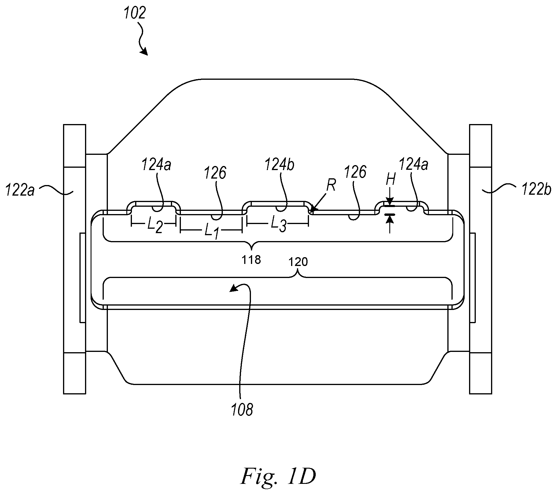
FIGS. 1C and 1D are isometric and top views, respectively, of a frame of the web adjuster shown in FIGS. 1A and 1B.
FIG. 2 is a side view of a child seat secured to a vehicle seat with a restraint system having a web adjuster configured in accordance with an embodiment of the present technology.
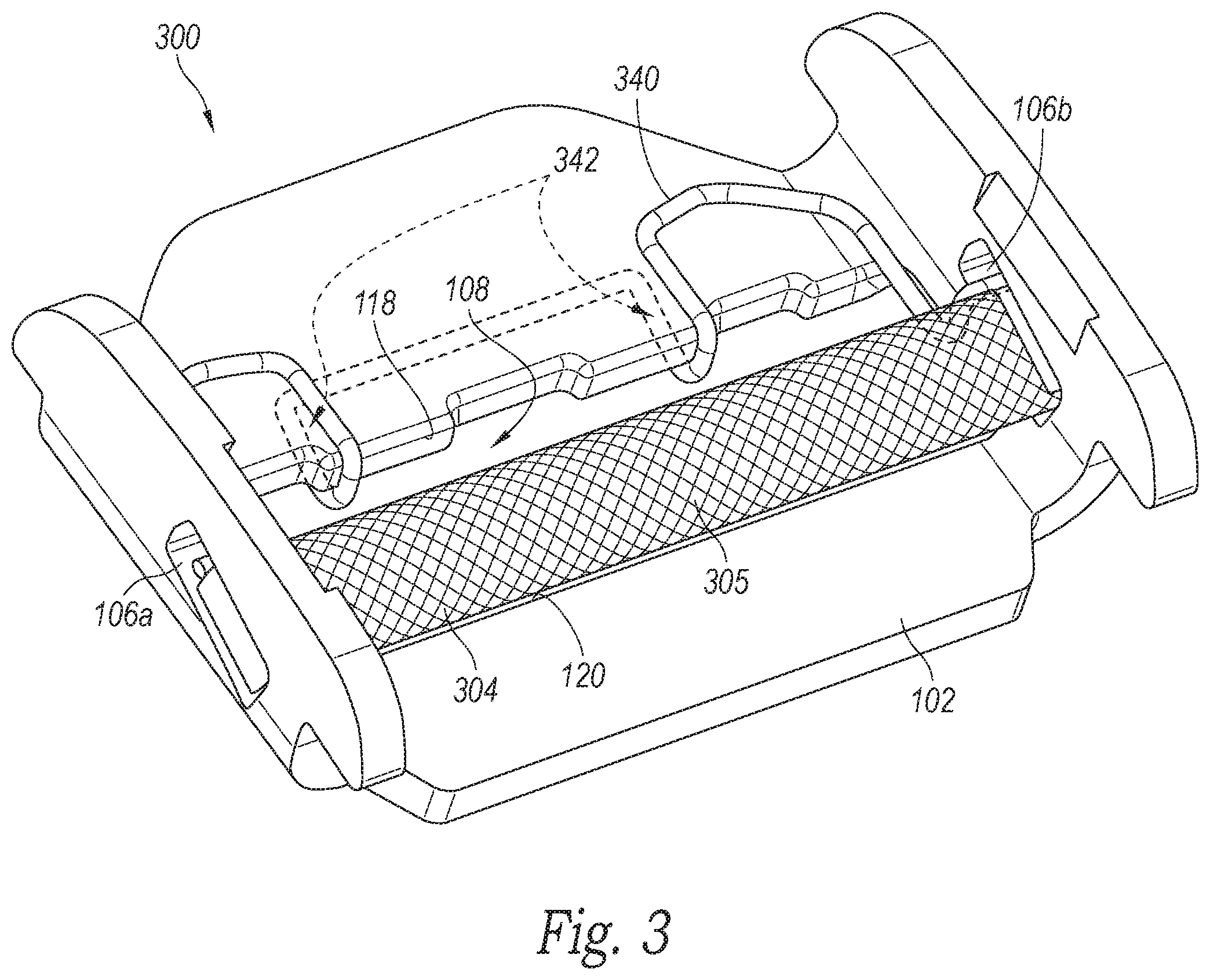
FIG. 3 is an isometric view of a web adjuster configured in accordance with another embodiment of the present technology.
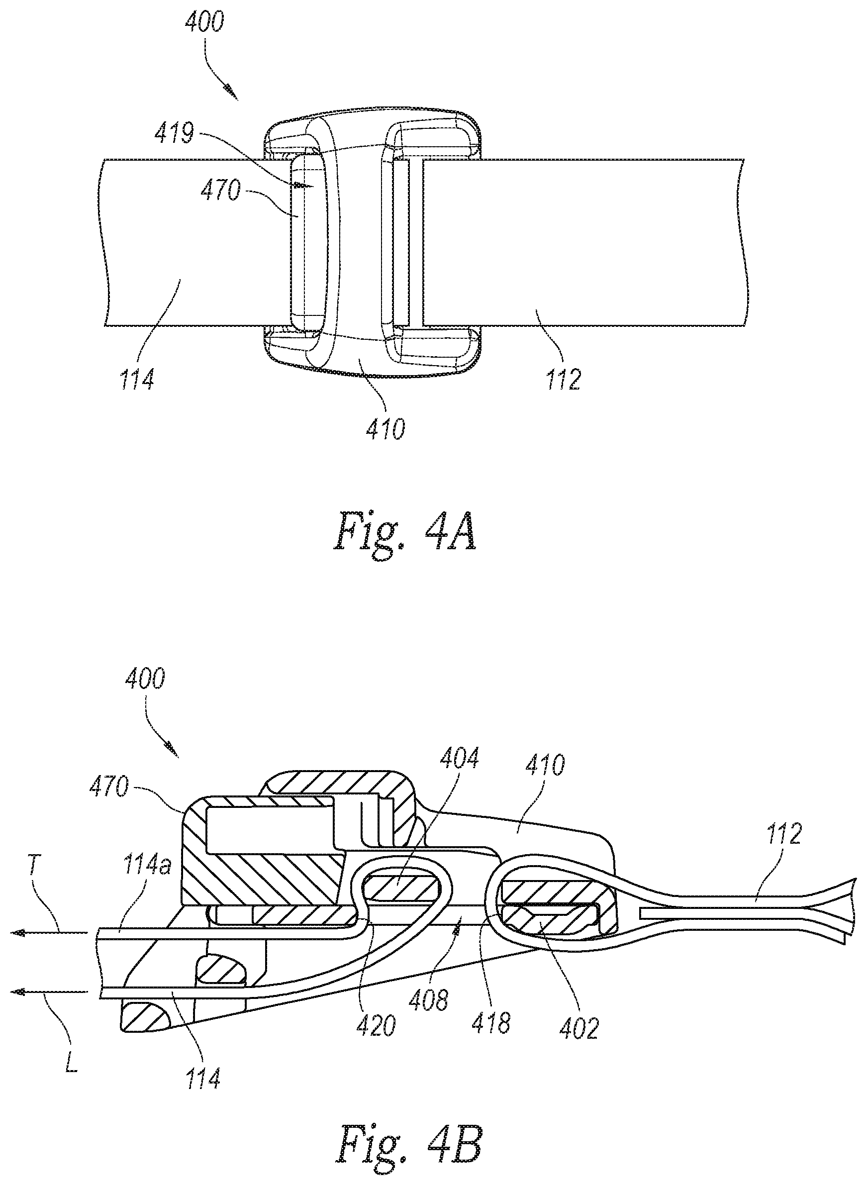
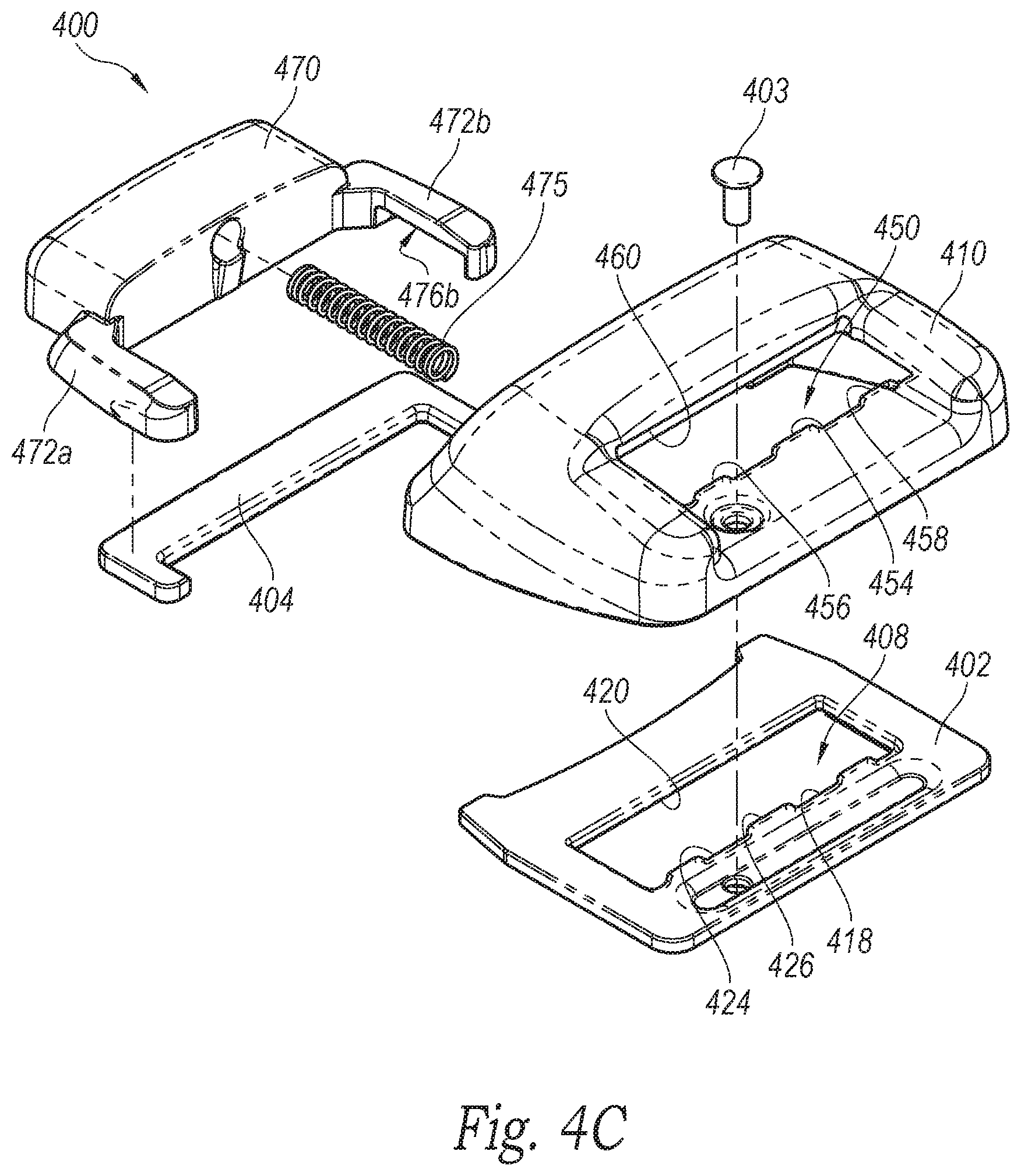
FIGS. 4A-4C are top, cross-sectional side, and exploded views, respectively, of a web adjuster configured in accordance with another embodiment of the present technology.
DETAILED DESCRIPTION
The following disclosure describes various embodiments of web adjusters and other web-related devices for use with personal restraint systems in land vehicles and other vehicles. In some embodiments, web adjusters configured in accordance with the present technology have frames with web gripping features configured to reduce web misalignment in use. Certain details are set forth in the following description and in FIGS. 1A-4C to provide a thorough understanding of various embodiments of the present technology. In other instances, well-known structures, materials, operations and/or systems often associated with seatbelt webs, web adjusters and other personal restraint system hardware are not shown or described in detail in the following disclosure to avoid unnecessarily obscuring the description of the various embodiments of the technology. Those of ordinary skill in the art will recognize, however, that the present technology can be practiced without one or more of the details set forth herein, or with other structures, methods, components, and so forth.
The terminology used below is to be interpreted in its broadest reasonable manner, even though it is being used in conjunction with a detailed description of certain examples of embodiments of the technology. Indeed, certain terms may even be emphasized below; however, any terminology intended to be interpreted in any restricted manner will be overtly and specifically defined as such in this Detailed Description section.
The accompanying Figures depict embodiments of the present technology and are not intended to be limiting of its scope. The sizes of various depicted elements are not necessarily drawn to scale, and these various elements may be arbitrarily enlarged to improve legibility. Component details may be abstracted in the Figures to exclude details such as position of components and certain precise connections between such components when such details are unnecessary for a complete understanding of how to make and use the invention. Many of the details, dimensions, angles and other features shown in the Figures are merely illustrative of particular embodiments of the disclosure. Accordingly, other embodiments can have other details, dimensions, angles and features without departing from the spirit or scope of the present invention. In addition, those of ordinary skill in the art will appreciate that further embodiments of the invention can be practiced without several of the details described below.
In the Figures, identical reference numbers identify identical, or at least generally similar, elements. To facilitate the discussion of any particular element, the most significant digit or digits of any reference number refers to the Figure in which that element is first introduced. For example, element 110 is first introduced and discussed with reference to FIG. 1.
FIGS. 1A and 1B are isometric and cross-sectional isometric views, respectively, of a web adjuster 100 having a frame 102 configured in accordance with an embodiment of the present technology. FIGS. 1C and 1D are enlarged isometric and top views, respectively, of the frame 102. Referring first to FIGS. 1C and 1D together, in the illustrated embodiment the frame 102 includes a first sidewall portion 122a and a second sidewall portion 122b extending upwardly from opposite sides of a base portion 128. The base portion 128 includes a web aperture 108 (e.g. a generally rectangular web aperture) that extends generally lengthwise across the base portion 128 between the sidewall portions 122, b. The web aperture 108 includes a first edge 118 (e.g., an "anchor side" edge) opposite a second edge 120 (e.g., an "adjust side" edge).
In one aspect of this embodiment, at least a portion of the first edge 118 has a nonlinear shape defined by a plurality of recessed portions 124 (identified as recessed portions 124a and 124b) separated by corresponding raised portions 126 (which can also be referred to as "projections" or "protrusions"). As described in greater detail below, the alternating recessed/raised portions form web gripping features that can prevent a web that extends around the first edge 118 from sliding from one side of the frame 102 to the other side if, for example, the web is pulled in a direction that is not perpendicular to the first edge 118. In some embodiments, the first edge 118 can include at least two raised portions 126 and at least three recessed portions 124. More particularly, with reference to FIG. 1D, in some embodiments, the first edge 118 can include two outer recessed portions 124a and an inner recessed portion 124b. In some embodiments, each of the raised portions 126 can have a length L.sub.1 between 3.0-10.0 mm (e.g., about 8.0 mm) and a height H between 0.10-2.5 mm (e.g., about 1.0 mm) selected to inhibit the web from moving sideways relative to the frame 102. In some embodiments, the outer recessed portions 124a can have a length L.sub.2 less than a length L.sub.3 of the inner recessed portion 124b. For example, in some embodiments, the length L.sub.2 can be about 5.0 mm and the length L.sub.3 can be about 7.0 mm. In other embodiments, the raised portions 126 and the recessed portions 124 can have other dimensions, and in some embodiments, individual ones of the raised portions 126 and/or recessed portions 124 can have the same or different lengths. Additionally, although the raised and recessed portions 124, 126 have generally "squared-off" corners in the illustrated embodiment, the raised portions 126 can have lateral corners 121 that are rounded with a radius R of, for example, about 0.50 mm. The height H, length L.sub.1, and/or the radius R of the lateral corners 121 of the raised portions 126 can be selected to secure the web without cutting or otherwise degrading the web under a load or in normal use. The foregoing dimensions are illustrative of one embodiment of the present technology. Accordingly, other embodiments can have other dimensions in accordance with the present disclosure. For example, in some embodiments, each of the lengths L.sub.1, L.sub.2, and L.sub.3 can be generally the same.
In another aspect of the embodiment illustrated in FIG. 1C, corners 123 between the first edge 118 and the second edge 120 and the upper and lower surfaces of the base portion 128 are generally rounded with a radius selected to inhibit the respective webs from slipping through the web aperture 108 without cutting or otherwise degrading the webs under a load or in normal use. In some embodiments, for example, the radius of the corners 123 can be between 0.30-0.70 mm. In other embodiments, the corners 123 can have different dimensions.
Although the illustrated embodiment depicts a series of alternating recessed portions 124 and raised portions 126 having a generally square or rectangular periodic configuration, in other embodiments the first edge 118 can include a variety of other web gripping features configured to prevent the web from sliding from side to side in the web aperture 108. Such web gripping features can include, for example, a series of curved alternating raised and recessed portions (having, e.g., a sinusoidal shape), a saw tooth configuration, a series of adjacent bumps or scallops, and/or other nonlinear edge features, etc.
Referring next to FIGS. 1A and 1B together with FIG. 1C, each of the sidewall portions 122a, b includes a corresponding opening or slot 106a, b that is configured to slideably receive an end portion (e.g., a generally rectangular end portion) of a cross bar 104 (FIG. 1B). Additionally, the web adjuster 100 includes a cover or housing 110 that is securely attached to the sidewall portions 122a, b. As shown in, for example, FIG. 1B, the cover 110 encloses an upper portion of the frame 102 as well as the cross bar 104, while leaving the web aperture 108 open. The frame 102, the cross bar 104, and the cover 110 can be manufactured using suitable materials and methods known in the art. For example, in some embodiments, the frame 102 can be formed from a suitable steel, such as steel plate that is stamped and formed to shape, the cross bar 104 can be cast or machined from a suitable steel, and the cover 110 can be injection molded from a suitable plastic.
To use the web adjuster 100, a first web 112 can be looped through the web aperture 108 and around the first edge 118 before being stitched or otherwise attached to itself to securely attach the first web 112 to the frame 102. As described in greater detail below, the opposite end of the first web 112 (e.g., the "tag end") can carry, for example, a latch or other device to fixedly attach the first web 112 to an anchor in a vehicle. A second web 114 can be routed through the web aperture 108 and around the cross bar 104, and then back out the web aperture 108. The second web 114 includes a free end portion 114a, and an opposite end that is spaced apart from the web adjuster 100. As also described in greater detail below, the opposite end of the second web 114 can be secured to, for example, a child seat so that the first web 112 and the second web 114 together form a combined web that secures the child seat to the vehicle. The webs 112 and 114 can be any manner of conventional restraint straps, seat belt webs, etc. well known in the art, and can be constructed of various suitable materials known in the art, such as woven nylon.
The web adjuster 100 can be used in a wide variety of applications. FIG. 2, for example, is a side view of a child seat 230 secured in a car seat 232 with a restraint system 200 that includes the web adjuster 100 described in detail above. In the illustrated embodiment, an upper portion of the child seat 230 is securely attached to an upper anchor 234 in a vehicle by means of the first web 112 and the second web 114 which are coupled together by the web adjustor 100. Although the upper portion of the child seat 230 is secured to the upper anchor 234, in other embodiments the upper portion of the child seat 230 and/or other portions of the child seat 230 can be secured to a lower anchor 238 by means of the first and second webs 112 and 114 and the web adjuster 100. The lower portion of the child seat 230 can be secured to the car seat 232 with additional restraints, such as a restraint 236 of a type well known to those of ordinary skill in the art. In other embodiments, the web adjuster 100 can be used with various other web arrangements without departing from the spirit or scope of the present disclosure.
Referring to FIGS. 1A-2 together, in operation, the user can increase the tension in the first web 112 and the second web 114 by grasping the free end portion 114a and pulling it in direction T as shown in FIG. 1A. Pulling the free end portion 114a drives the cross bar 104 away from the second edge 120 of the frame 102 (FIGS. 1C and 1D), increasing the space therebetween and enabling the free end portion 114a to pull through the web aperture 108, thereby creating tension in the second web 114 in direction L. When the user releases the free end portion 114a, the tension in the web 114 drives the cross bar 104 back against the second edge 120, thereby locking the web 114 in position and maintaining the tension in the first and second webs 112 and 114. To release the tension in the first and second webs 112 and 114 so that, for example, the child seat 230 can be removed from the car seat 232, the user can rotate (i.e., tilt) the web adjuster 100 upwardly in direction R as shown in FIG. 1A. When this happens, it enables the cross bar 104 to slide in the slots 106a, b away from the second edge 120, thereby increasing the space therebetween and enabling the free end portion 114a to slide back into the web adjuster 100 to reduce the tension in the web 114. Accordingly, in the illustrated embodiment the web adjuster 100 can be referred to as a "tilt-lock" web adjuster because it can be tilted as described above to release the second web 114, and tilted back into position to lock the second web 114.
In some embodiments, the web adjuster 100 can include additional components and/or features configured in accordance with the present technology to facilitate operation and use. FIG. 3, for example, is an enlarged isometric view of a web adjuster 300 having a frame 102 and a cross bar 304. The web adjuster 300 is similar in structure and function to the web adjuster 100 described in detail above and can include a housing 110 that is omitted from FIG. 3 for purposes of clarity. In the illustrated embodiment, the cross bar 304 has a textured surface 305 configured to grip the second web 114. For example, the surface 305 can have a plurality of features (e.g., teeth, bumps, grooves, etc.) that help to grip the second web 114 to, for example, inhibit movement of the second web 114 through the web aperture 108 when the cross bar 304 is pressed toward the second edge 120. In some embodiments, the surface 305 is a knurled (e.g., diamond-knurled), etched, or otherwise textured surface. Additionally, in the illustrated embodiment, the cross bar 304 has a generally oblong (e.g., oval or elliptical) cross-sectional shape rather than a circular cross-sectional shape. In other embodiments, however, the cross bar 304 can have a circular, square, rectangular, polygonal, irregular, or other cross-sectional shape with or without a textured surface.
In some embodiments, the web adjuster 300 can include a biasing member 340 (e.g., a spring) configured to bias the cross bar 304 toward the second edge 120. In the illustrated embodiment, the biasing member 340 can be secured (e.g., clipped) to the frame 102 at the first edge 118 and can contact and press against the cross bar 304 proximate the slots 106a, b. For example, in some embodiments, the biasing member 340 can be formed from spring steel wire, and can include a pocket 342 that is shaped to receive and grasp the base portion 128 proximate to the first edge 118.
Referring to FIGS. 1A, 2 and 3 together, in operation, the user can increase tension in the first web 112 and the second web 114 by gripping the free end portion 114a and pulling in the direction T as described above with reference to FIG. 1A. This drives the cross bar 304 away from the second edge 120. When the user releases the free end portion 114a, the biasing force of the biasing member 340 combines with the tension in the second web 114 to drive the cross bar 304 back toward the second edge 120, thereby locking the second web 114 in position and maintaining the tension in the first and second webs 112 and 114.
Although, in the embodiments illustrated in FIGS. 1A-3 the web gripping features are described in the context of tilt-lock web adjusters, those of ordinary skill in the art will understand that the web gripping features described herein can be utilized with a wide variety of other web coupling devices, including other types of web adjusters, web retractors, latches, attachment fittings, etc. Accordingly, the non-slide web gripping features described herein are not limited to use with any particular web adjuster or web interface device, but can be used with a wide-variety of such devices without departing from the spirit or scope of the present disclosure.
For example, FIGS. 4A-4C are top, cross-sectional side, and exploded views, respectively, of a web adjuster 400 configured in accordance with another embodiment of the present technology. The web adjuster 400 can include some features that are generally similar to the features of the web adjusters 100, 300 described in detail above, and can be used to adjust the tension in the first and second webs 112, 114. However, in contrast to the web adjusters 100, 300, the web adjuster 400 can be a "push-button" type web adjuster. Referring first to FIG. 4C, the web adjuster 400 includes a frame 402 having a web aperture 408, and a cover or housing 410 that can be securely attached to the frame 402 via, for example, a fastener 403 (e.g., a rivet, screw, etc.). In the illustrated embodiment, the web aperture 408 includes a first edge 418 (e.g., an "anchor side" edge) opposite a second edge 420 (e.g., an "adjust side" edge). The first edge 418 can have a nonlinear shape defined by a plurality of recessed portions 424 separated by corresponding raised portions 426. In some embodiments, the recessed portions 424 and the raised portions 426 can have the same shapes and sizes as the recessed portions 124 and the raised portions 126 described in detail above. As described above, the recessed/raised portions form web gripping features that can inhibit a web that extends around the first edge 418 from moving side-to-side relative to the frame 402 if the web is, for example, pulled in a direction that is not perpendicular to the first edge 418.
In another aspect of the illustrated embodiment, the cover 410 can include a web aperture 450 having a first edge 458 and a second edge 460 opposite the first edge 458. In some embodiments, the web aperture 408 in the frame 402 can be generally aligned with the web aperture 450 in the cover, and/or the first edge 458 can have the same or a generally similar shape as the first edge 418 of the frame 402. For example, the first edge 458 can have a nonlinear shape (e.g., including alternating raised portions 456 and recessed portions 454 forming web gripping features) that matches the shape of the first edge 418 for inhibiting side-to-side movement of a web that extends around the first edge 458. In other embodiments, only one of the first edges 418, 458 can include web gripping features for securing the web. For example, in some embodiments the raised portions 426 can extend beyond the first edge 458 of the cover 410 toward the second edge 420, and the first edge 458 can be straight. In other embodiments, the raised portions 456 of the cover 410 can extend beyond the first edge 418 of the frame 402 in the direction toward the second edge 460.
As further shown in FIG. 4C, the web adjuster 400 can include a push button 470 having a first arm portion and 472a and a second arm portion 472b. Each of the arm portions 472a, b includes a corresponding opening or slot 476a, b (only the slot 476b is visible in FIG. 4C) that is configured to receive and secure an end portion (e.g., a generally rectangular end portion) of a cross bar 404. In the illustrated embodiment, a biasing member 475 (e.g., a spring) extends between and contacts the push button 470 and the cover 410. As shown in, for example, FIG. 4A, the push button 470 can be slidably received within a button aperture 419 in the cover 410. As shown in, for example, FIG. 4B, the cover 410 is attached to the frame 402 and encloses the cross bar 404, while leaving the web aperture 408 generally open.
Referring to FIGS. 4A-4C together, to use the web adjuster 400, the first web 112 can be looped through the web apertures 408, 450 and around the first edges 418, 458 before being stitched or otherwise attached to itself to securely attach the first web 112 to the frame 402. The second web 114 can be routed through the web aperture 408 and around the cross bar 404, and then back out the web aperture 408. The user can increase tension in the first web 112 and the second web 114 by gripping the free end portion 114a and pulling in the direction T (FIG. 4B). This drives the cross bar 404 away from the second edge 420 of the web aperture 408, increasing the space therebetween and enabling the free end portion 114a to pull through the web aperture 408, thereby creating tension in the second web 114 in the direction L (FIG. 4B). Driving the cross bar 404 away from the second edge 420 causes the push button 470 to move inward through the button aperture 419 and at least partially into the cover 410. In some embodiments, while pulling the free end portion 114a in the direction T, the user can push the push button 470 inward to further increase or maintain the spacing between the cross bar 404 and the second edge 420. When the user releases the free end portion 114a, the biasing force of the biasing member 475 combines with the tension in the second web 114 to drive the cross bar 404 toward the second edge 420, thereby locking the second web 114 in position and maintaining the tension in the first and second webs 112 and 114. Driving the cross bar 404 toward the second edge 420 causes the bush button 470 to move outwardly through the button aperture 419 and at least partially out of the cover 410.
To release the tension in the first and second webs 112 and 114, the user can push the push button 470 inward to drive the cross bar 404 away from the second edge 420, thereby increasing the space therebetween and enabling the free end portion 114a to slide back into the web adjuster 400 to reduce the tension in the web 114. Accordingly, in the illustrated embodiment the web adjuster 100 can be referred to as a "push-button" web adjuster because it can be actuated as described above to release the second web 114, and released to lock the second web 114.
In conventional web adjusters in which the web loops around a straight interface edge for attachment to the adjuster frame, the web may have a tendency to slide to one side of the edge or the other in use, especially if the web is pulled or otherwise placed in tension at an angle that is not perpendicular to, or at least substantially perpendicular to, the edge. This can occur, for example, if the tag end of a web is secured to the adjuster frame around a straight edge, and the free end of a web looped around the cross bar is pulled in a direction that is not perpendicular to the straight edge. For example, loads on the web during a vehicle accident can potentially cause sliding of the web to one side or the other of the adjuster. Sliding of the web may increase the stress on the web in use and may reduce the load-carrying capability of the web. Providing the web interface edges of web adjusters with the web gripping features described above with reference to FIGS. 1C and 4C (e.g., scalloped edges, nonlinear edges, etc.), however, can prevent this undesirable sliding--thereby preserving the load-carrying capability of the web--by creating friction and/or interference that prevents or at least substantially reduces movement of the web to one side of the adjuster or the other.
References throughout the foregoing description to features, advantages, or similar language do not imply that all of the features and advantages that may be realized with the present technology should be or are in any single embodiment of the invention. Rather, language referring to the features and advantages is understood to mean that a specific feature, advantage, or characteristic described in connection with an embodiment is included in at least one embodiment of the present technology. Thus, discussion of the features and advantages, and similar language, throughout this specification may, but do not necessarily, refer to the same embodiment. Furthermore, the described features, advantages, and characteristics of the present technology may be combined in any suitable manner in one or more embodiments. One skilled in the relevant art will recognize that the present technology can be practiced without one or more of the specific features or advantages of a particular embodiment. In other instances, additional features and advantages may be recognized in certain embodiments that may not be present in all embodiments of the present technology.
Any patents and applications and other references noted above, including any that may be listed in accompanying filing papers, are incorporated herein by reference. Aspects of the invention can be modified, if necessary, to employ the systems, functions, and concepts of the various references described above to provide yet further implementations of the invention.
Unless the context clearly requires otherwise, throughout the description and the claims, the words "comprise," "comprising," and the like are to be construed in an inclusive sense, as opposed to an exclusive or exhaustive sense; that is to say, in the sense of "including, but not limited to." As used herein, the terms "connected," "coupled," or any variant thereof means any connection or coupling, either direct or indirect, between two or more elements; the coupling or connection between the elements can be physical, logical, or a combination thereof. Additionally, the words "herein," "above," "below," and words of similar import, when used in this application, refer to this application as a whole and not to any particular portions of this application. Where the context permits, words in the above Detailed Description using the singular or plural number may also include the plural or singular number respectively. The word "or," in reference to a list of two or more items, covers all of the following interpretations of the word: any of the items in the list, all of the items in the list, and any combination of the items in the list.
The above Detailed Description of examples and embodiments of the invention is not intended to be exhaustive or to limit the invention to the precise form disclosed above. While specific examples for the invention are described above for illustrative purposes, various equivalent modifications are possible within the scope of the invention, as those skilled in the relevant art will recognize. The teachings of the invention provided herein can be applied to other systems, not necessarily the system described above. The elements and acts of the various examples described above can be combined to provide further implementations of the invention. Some alternative implementations of the invention may include not only additional elements to those implementations noted above, but also may include fewer elements. Further any specific numbers noted herein are only examples: alternative implementations may employ differing values or ranges.
While the above description describes various embodiments of the invention and the best mode contemplated, regardless how detailed the above text, the invention can be practiced in many ways. Details of the system may vary considerably in its specific implementation, while still being encompassed by the present disclosure. As noted above, particular terminology used when describing certain features or aspects of the invention should not be taken to imply that the terminology is being redefined herein to be restricted to any specific characteristics, features, or aspects of the invention with which that terminology is associated. In general, the terms used in the following claims should not be construed to limit the invention to the specific examples disclosed in the specification, unless the above Detailed Description section explicitly defines such terms. Accordingly, the actual scope of the invention encompasses not only the disclosed examples, but also all equivalent ways of practicing or implementing the invention under the claims.
From the foregoing, it will be appreciated that specific embodiments of the invention have been described herein for purposes of illustration, but that various modifications may be made without deviating from the spirit and scope of the various embodiments of the invention. Further, while various advantages associated with certain embodiments of the invention have been described above in the context of those embodiments, other embodiments may also exhibit such advantages, and not all embodiments need necessarily exhibit such advantages to fall within the scope of the invention. Accordingly, the invention is not limited, except as by the appended claims.
Although certain aspects of the invention are presented below in certain claim forms, the applicant contemplates the various aspects of the invention in any number of claim forms. Accordingly, the applicant reserves the right to pursue additional claims after filing this application to pursue such additional claim forms, in either this application or in a continuing application.
* * * * *
References
-
britax.com.au/car-seats/compaq
-
holmbergs.se
-
-
holmbergs.se1/1/1.0.1.0/53/1
-
-
-
-
novarace.com/index.php?option=com_content&task=view&id=36&Itemid=48
-
-
-
-
-
childsafety.sabelt.com/index.php/eshop/product/Sabelt-Racing-DAPHNE-0.html/1
-
-
-
D00000
D00001
D00002
D00003
D00004
D00005
D00006
D00007
XML
uspto.report is an independent third-party trademark research tool that is not affiliated, endorsed, or sponsored by the United States Patent and Trademark Office (USPTO) or any other governmental organization. The information provided by uspto.report is based on publicly available data at the time of writing and is intended for informational purposes only.
While we strive to provide accurate and up-to-date information, we do not guarantee the accuracy, completeness, reliability, or suitability of the information displayed on this site. The use of this site is at your own risk. Any reliance you place on such information is therefore strictly at your own risk.
All official trademark data, including owner information, should be verified by visiting the official USPTO website at www.uspto.gov. This site is not intended to replace professional legal advice and should not be used as a substitute for consulting with a legal professional who is knowledgeable about trademark law.