Peritoneal dialysis systems, devices, and methods
Burbank , et al.
U.S. patent number 10,610,630 [Application Number 15/476,714] was granted by the patent office on 2020-04-07 for peritoneal dialysis systems, devices, and methods. This patent grant is currently assigned to NxStage Medical, Inc.. The grantee listed for this patent is NxStage Medical, Inc.. Invention is credited to James M. Brugger, Jeffrey H. Burbank, Dennis M. Treu, Mark T. Wyeth.


View All Diagrams
| United States Patent | 10,610,630 |
| Burbank , et al. | April 7, 2020 |
Peritoneal dialysis systems, devices, and methods
Abstract
A method of performing a peritoneal dialysis treatment includes connecting a disposable unit to a source of water, the disposable unit including at least a first container holding a sterile concentrate containing an osmotic agent, a second container holding a sterile concentrate containing electrolytes, an empty sterile mixing container, and a tubing set with a pre-attached peritoneal fill/drain line. The method further includes receiving a prescription command by a controller, indicating at least the fill volume and desired final concentration of the osmotic agent to be used for a current fill cycle under said treatment, and using the controller, pumping a quantity of the concentrated osmotic agent that is at least sufficient to achieve the desired final concentration into the mixing container. The contents of the mixing container are mixed, further diluted or concentrated, and then flowed to a patient.
| Inventors: | Burbank; Jeffrey H. (Boxford, MA), Brugger; James M. (Newburyport, MA), Treu; Dennis M. (Castle Rock, CO), Wyeth; Mark T. (Gibsonia, PA) | ||||||||||
|---|---|---|---|---|---|---|---|---|---|---|---|
| Applicant: |
|
||||||||||
| Assignee: | NxStage Medical, Inc.
(Lawrence, MA) |
||||||||||
| Family ID: | 46880067 | ||||||||||
| Appl. No.: | 15/476,714 | ||||||||||
| Filed: | March 31, 2017 |
Prior Publication Data
| Document Identifier | Publication Date | |
|---|---|---|
| US 20170203027 A1 | Jul 20, 2017 | |
Related U.S. Patent Documents
| Application Number | Filing Date | Patent Number | Issue Date | ||
|---|---|---|---|---|---|
| 15400978 | Jan 7, 2017 | 10046100 | |||
| 14006763 | 9907897 | ||||
| PCT/US2012/030350 | Mar 23, 2012 | ||||
| 61466921 | Mar 23, 2011 | ||||
| 61490183 | May 26, 2011 | ||||
| 61509240 | Jul 19, 2011 | ||||
| Current U.S. Class: | 1/1 |
| Current CPC Class: | A61M 1/1674 (20140204); A61M 1/281 (20140204); A61M 1/287 (20130101); A61M 1/288 (20140204); A61M 1/166 (20140204); A61M 1/1672 (20140204); A61M 1/167 (20140204); A61M 1/1656 (20130101); A61M 1/285 (20130101); A61M 1/282 (20140204); A61M 1/1668 (20140204); A61M 1/28 (20130101); A61M 1/1664 (20140204); A61M 2205/12 (20130101); A61M 2205/33 (20130101); A61M 2025/0002 (20130101); A61M 2230/005 (20130101); A61M 2205/128 (20130101); A61M 2205/14 (20130101); A61M 2205/3351 (20130101); A61M 2205/3355 (20130101); A61M 2205/123 (20130101); A61M 2205/3331 (20130101); A61M 2205/18 (20130101); A61M 2205/52 (20130101); A61M 2205/3334 (20130101) |
| Current International Class: | A61M 1/28 (20060101); A61M 1/16 (20060101); A61M 25/00 (20060101) |
References Cited [Referenced By]
U.S. Patent Documents
| 2369070 | February 1945 | Nielsen |
| 2575447 | November 1951 | Gossick |
| 2874351 | February 1959 | John |
| 3490591 | January 1970 | Jones et al. |
| 3526834 | September 1970 | Brown |
| 3786810 | January 1974 | Pannier et al. |
| 3847809 | November 1974 | Kopf |
| 4138639 | February 1979 | Hutchins |
| 4161264 | July 1979 | Malmgren et al. |
| 4209391 | June 1980 | Lipps et al. |
| 4338190 | July 1982 | Kraus et al. |
| 4396382 | August 1983 | Goldhaber |
| 4412834 | November 1983 | Kulin et al. |
| 4420752 | December 1983 | Davis et al. |
| 4432759 | February 1984 | Gross et al. |
| 4432765 | February 1984 | Oscarsson |
| 4435171 | March 1984 | Goldberg et al. |
| 4439179 | March 1984 | Lueders et al. |
| 4439188 | March 1984 | Dennehey et al. |
| 4440207 | April 1984 | Genatempo et al. |
| 4447230 | May 1984 | Gula et al. |
| 4479760 | October 1984 | Bilstad et al. |
| 4489535 | December 1984 | Veltman |
| 4526572 | July 1985 | Donnan et al. |
| 4553552 | November 1985 | Valdespino et al. |
| 4605895 | August 1986 | Park |
| 4617115 | October 1986 | Vantard |
| 4618343 | October 1986 | Polaschegg |
| 4636204 | January 1987 | Christopherson et al. |
| 4655742 | April 1987 | Vantard |
| 4657529 | April 1987 | Prince et al. |
| 4663006 | May 1987 | Yao et al. |
| 4670007 | June 1987 | Wheeldon et al. |
| 4747822 | May 1988 | Peabody |
| 4747950 | May 1988 | Guinn |
| 4797191 | January 1989 | Metzner et al. |
| 4823833 | April 1989 | Hogan et al. |
| 4825168 | April 1989 | Ogawa et al. |
| 4846950 | July 1989 | Yao et al. |
| 4857199 | August 1989 | Cortial |
| 4876515 | October 1989 | Ball |
| 4954782 | September 1990 | Ball |
| 4997570 | March 1991 | Polaschegg |
| 5004535 | April 1991 | Bosko et al. |
| 5062774 | November 1991 | Kramer et al. |
| 5087245 | February 1992 | Doan |
| 5141493 | August 1992 | Jacobsen et al. |
| 5225783 | July 1993 | Suzuki et al. |
| 5326476 | July 1994 | Grogan et al. |
| 5336173 | August 1994 | Folden |
| 5344392 | September 1994 | Senninger et al. |
| 5346472 | September 1994 | Keshaviah |
| 5442969 | August 1995 | Troutner et al. |
| 5485083 | January 1996 | Pulice |
| 5486286 | January 1996 | Peterson et al. |
| 5522998 | June 1996 | Polaschegg |
| 5567320 | October 1996 | Goux |
| 5570026 | October 1996 | Buffaloe, IV et al. |
| 5628908 | May 1997 | Kamen et al. |
| 5631552 | May 1997 | Ogawa et al. |
| 5650071 | July 1997 | Brugger et al. |
| 5674390 | October 1997 | Matthews et al. |
| 5725773 | March 1998 | Polaschegg |
| 5800363 | September 1998 | Chandler et al. |
| 5836933 | November 1998 | Buttitta et al. |
| 5865764 | February 1999 | Moorhead |
| 5895578 | April 1999 | Simard et al. |
| 5900136 | May 1999 | Gotsu et al. |
| 5925011 | July 1999 | Faict et al. |
| 5938634 | August 1999 | Packard |
| 6036680 | March 2000 | Horne et al. |
| 6129699 | October 2000 | Haight et al. |
| 6136201 | October 2000 | Shah et al. |
| 6139754 | October 2000 | Hartranft et al. |
| 6156797 | December 2000 | Kubo et al. |
| 6168578 | January 2001 | Diamond |
| 6196991 | March 2001 | Keilman |
| 6228047 | May 2001 | Dadson |
| 6241943 | June 2001 | Wieslander et al. |
| 6270673 | August 2001 | Belt et al. |
| 6280634 | August 2001 | Shah et al. |
| 6327895 | December 2001 | Jeppsson et al. |
| 6391404 | May 2002 | Rosenbaum et al. |
| 6423029 | July 2002 | Elsberry |
| 6460592 | October 2002 | Sano et al. |
| 6463979 | October 2002 | Sano et al. |
| 6471855 | October 2002 | Odak et al. |
| 6488647 | December 2002 | Miura et al. |
| 6489785 | December 2002 | McAllister |
| 6491658 | December 2002 | Miura et al. |
| 6492336 | December 2002 | Mahiout |
| 6503062 | January 2003 | Gray et al. |
| 6537976 | March 2003 | Gupta |
| 6585682 | July 2003 | Haraldsson et al. |
| 6591126 | July 2003 | Roeper et al. |
| 6595948 | July 2003 | Suzuki et al. |
| 6605214 | August 2003 | Taylor |
| 6610206 | August 2003 | Callan et al. |
| 6645191 | November 2003 | Knerr et al. |
| 6648906 | November 2003 | Lasheras et al. |
| 6666842 | December 2003 | Sakai |
| 6689275 | February 2004 | Gupta |
| 6705372 | March 2004 | Sano et al. |
| 6738052 | May 2004 | Manke et al. |
| 6749580 | June 2004 | Work et al. |
| 6758975 | July 2004 | Peabody et al. |
| 6769231 | August 2004 | Danby |
| 6803363 | October 2004 | Polaschegg |
| 6808369 | October 2004 | Gray et al. |
| 6814869 | November 2004 | Brandl et al. |
| 6861033 | March 2005 | Mullins et al. |
| 6877713 | April 2005 | Gray et al. |
| 6887214 | May 2005 | Levin |
| 6889713 | May 2005 | Navis |
| 6911014 | June 2005 | Wentling et al. |
| 6912917 | July 2005 | Brugger et al. |
| 6929751 | August 2005 | Bowman et al. |
| 6981977 | January 2006 | Herweck et al. |
| 6986752 | January 2006 | McGuckin et al. |
| 6995563 | February 2006 | Talutis |
| 7013928 | March 2006 | Navis |
| 7033539 | April 2006 | Krensky et al. |
| 7053059 | May 2006 | Zieske et al. |
| 7057400 | June 2006 | Gaignet |
| 7067061 | June 2006 | Bosetto et al. |
| 7083719 | August 2006 | Bowman et al. |
| 7119305 | October 2006 | Sano et al. |
| 7138088 | November 2006 | Wariar et al. |
| 7175606 | February 2007 | Bowman, Jr. et al. |
| 7214228 | May 2007 | Crabtree |
| 7235569 | June 2007 | Hausheer |
| 7243893 | July 2007 | Sobue et al. |
| 7250619 | July 2007 | Taylor et al. |
| 7320676 | January 2008 | Miesel |
| 7354190 | April 2008 | Demers et al. |
| 7410475 | August 2008 | Krensky et al. |
| 7421316 | September 2008 | Gray et al. |
| 7441108 | October 2008 | Fisher et al. |
| 7459054 | December 2008 | Landherr et al. |
| 7544301 | June 2009 | Shah et al. |
| 7559483 | July 2009 | Hickle et al. |
| 7559524 | July 2009 | Gray et al. |
| 7559913 | July 2009 | Jeppsson et al. |
| 7641753 | January 2010 | Gao et al. |
| 7670491 | March 2010 | Callan et al. |
| 7686279 | March 2010 | Nerbonne et al. |
| 7758552 | July 2010 | Zoltan et al. |
| 7763013 | July 2010 | Baldwin et al. |
| 7803628 | September 2010 | Glocker |
| 7837666 | November 2010 | Jensen et al. |
| 7842002 | November 2010 | Mantle |
| 7847564 | December 2010 | Rossi |
| 7857805 | December 2010 | Raines |
| 7862530 | January 2011 | Callan et al. |
| 7867214 | January 2011 | Childers et al. |
| 7883725 | February 2011 | Shah et al. |
| 7892423 | February 2011 | Rohde et al. |
| 7901376 | March 2011 | Steck et al. |
| 7905853 | March 2011 | Chapman et al. |
| 7905855 | March 2011 | Childers |
| 7935074 | May 2011 | Plahey et al. |
| 7955295 | June 2011 | Lee et al. |
| 7988849 | August 2011 | Biewer et al. |
| 7993050 | August 2011 | Demers et al. |
| 8034017 | October 2011 | Petersen |
| 8083709 | December 2011 | Childers et al. |
| 8088094 | January 2012 | Hamada et al. |
| 8096969 | January 2012 | Roberts et al. |
| 8105487 | January 2012 | Fulkerson et al. |
| 8147696 | April 2012 | Pandya |
| 8178040 | May 2012 | Brauer |
| 8202547 | June 2012 | Shah et al. |
| 8222229 | July 2012 | Kiribayashi et al. |
| 8287724 | October 2012 | Slepicka et al. |
| 8297954 | October 2012 | Moubayed |
| 8298167 | October 2012 | Peters et al. |
| 8298170 | October 2012 | Lundtveit et al. |
| 8308128 | November 2012 | Mackal |
| 8348904 | January 2013 | Petersen |
| 8361009 | January 2013 | Lee et al. |
| 8367731 | February 2013 | Wieslander et al. |
| 8375797 | February 2013 | Beden et al. |
| 8382447 | February 2013 | Wang et al. |
| 8398590 | March 2013 | Sternberg et al. |
| 8414686 | April 2013 | Gura et al. |
| 8414768 | April 2013 | Shah et al. |
| 8431086 | April 2013 | Lurvey et al. |
| 8444593 | May 2013 | Hamada et al. |
| 8449496 | May 2013 | Hamada et al. |
| 8460544 | June 2013 | Volker |
| 8474784 | July 2013 | Kashmirian et al. |
| 8491184 | July 2013 | Kamen et al. |
| 8500676 | August 2013 | Jansson et al. |
| 8501009 | August 2013 | Peterson et al. |
| 8516902 | August 2013 | Beavis et al. |
| 8529496 | September 2013 | Britton et al. |
| 8540886 | September 2013 | Hedmann et al. |
| 8556225 | October 2013 | Gray |
| 8560510 | October 2013 | Brueggerhoff et al. |
| 8587516 | November 2013 | Kopychev et al. |
| 8597229 | December 2013 | Pan |
| 8600772 | December 2013 | Bacon |
| 8613739 | December 2013 | Sobue |
| 8641685 | February 2014 | Mansour et al. |
| 8671996 | March 2014 | Weilhoefer et al. |
| 8678224 | March 2014 | Ayot et al. |
| 8685251 | April 2014 | Smejtek et al. |
| 8698741 | April 2014 | Wang et al. |
| 8708992 | April 2014 | Kobayashi et al. |
| 8728056 | May 2014 | Colantonio et al. |
| 8731726 | May 2014 | Gray et al. |
| 8740864 | June 2014 | Hoang et al. |
| 8741131 | June 2014 | Bedingfield et al. |
| 8747370 | June 2014 | Feith et al. |
| 8758626 | June 2014 | Wong |
| 8764702 | July 2014 | Childers et al. |
| 8774885 | July 2014 | Abreu |
| 8777892 | July 2014 | Sandford et al. |
| 8789558 | July 2014 | Volker |
| 8801652 | August 2014 | Landherr et al. |
| 8801677 | August 2014 | Wallin |
| 8808595 | August 2014 | Babrowicz et al. |
| 8813769 | August 2014 | Gastauer et al. |
| 8815095 | August 2014 | Micheli |
| 8828232 | September 2014 | Shah et al. |
| 8834718 | September 2014 | Randall et al. |
| 8834719 | September 2014 | Childers et al. |
| 8838395 | September 2014 | Matsiev et al. |
| 8840581 | September 2014 | McGill et al. |
| 8858792 | October 2014 | Ding et al. |
| 8869612 | October 2014 | Chen et al. |
| 8870812 | October 2014 | Alberti et al. |
| 8682700 | November 2014 | Chapman et al. |
| 8875748 | November 2014 | Beden et al. |
| 8876753 | November 2014 | Roberts et al. |
| 8924458 | December 2014 | Levin et al. |
| 8926550 | January 2015 | Plahey et al. |
| 8926551 | January 2015 | Lo et al. |
| 8930213 | January 2015 | Gotlib et al. |
| 8945042 | February 2015 | Lee et al. |
| 8961444 | February 2015 | Chapman et al. |
| 8961466 | February 2015 | Steinbach |
| 8980070 | March 2015 | Nishio et al. |
| 8989906 | March 2015 | Gray et al. |
| 8992454 | March 2015 | Anand |
| 8992777 | March 2015 | Doyle |
| 9004886 | April 2015 | Beck et al. |
| 9014775 | April 2015 | Bennett et al. |
| 9022969 | May 2015 | Helmore et al. |
| 9044544 | June 2015 | Lo et al. |
| 9060727 | June 2015 | Saikley et al. |
| 9066968 | June 2015 | Ohta et al. |
| 9067017 | June 2015 | Tan et al. |
| 9069886 | June 2015 | Shimizu et al. |
| 9108031 | August 2015 | Brandenburger et al. |
| 9112245 | August 2015 | Yen |
| 9132220 | September 2015 | Kugelmann et al. |
| 9138523 | September 2015 | Burnett et al. |
| 9152918 | October 2015 | McNair |
| 9153002 | October 2015 | Jones et al. |
| 9162044 | October 2015 | Traversaz |
| 9165112 | October 2015 | Doyle et al. |
| 9180238 | November 2015 | Bedingfield et al. |
| 9198830 | December 2015 | Kugelmann et al. |
| 9199070 | December 2015 | Wegener et al. |
| 9216247 | December 2015 | Callan et al. |
| 9217702 | December 2015 | Sullivan |
| 9242035 | January 2016 | Karoor |
| 9254356 | February 2016 | Shah et al. |
| 9254358 | February 2016 | Volker |
| 9274073 | March 2016 | Nier et al. |
| 9284960 | March 2016 | Chappel et al. |
| 9308309 | April 2016 | Hedmann et al. |
| 9310232 | April 2016 | Heide et al. |
| 9319110 | April 2016 | Kopychev et al. |
| 9320680 | April 2016 | Schroder |
| 9345871 | May 2016 | Guala |
| 9358332 | June 2016 | McGill et al. |
| 9381290 | July 2016 | Yu et al. |
| 9393356 | July 2016 | Karoor et al. |
| 9408958 | August 2016 | Wang et al. |
| 9427518 | August 2016 | Brueckner |
| 9433768 | September 2016 | Tekeste et al. |
| 9440016 | September 2016 | Lin et al. |
| 9440019 | September 2016 | Falkenhagen et al. |
| 9470220 | October 2016 | Becker |
| 9471754 | October 2016 | Mastalli et al. |
| 9474841 | October 2016 | Volker |
| 9495511 | November 2016 | Harrington et al. |
| 9500188 | November 2016 | Ly et al. |
| 9514131 | December 2016 | Bochenko et al. |
| 9519969 | December 2016 | Kusens |
| 9539387 | January 2017 | Fini et al. |
| 9555232 | January 2017 | Davis et al. |
| 9593679 | March 2017 | Gray et al. |
| 9610518 | April 2017 | Kamen et al. |
| 9616163 | April 2017 | Wong et al. |
| 9629993 | April 2017 | Klewinghaus |
| 9651511 | May 2017 | Howell et al. |
| 9669145 | June 2017 | Gunther et al. |
| 9677555 | June 2017 | Kamen et al. |
| 9687646 | June 2017 | Sobue et al. |
| 9694125 | July 2017 | Plahey et al. |
| 9694126 | July 2017 | Hedmann et al. |
| 9700711 | July 2017 | Grant et al. |
| 9724270 | August 2017 | Bonnal et al. |
| 9724298 | August 2017 | Nilsson et al. |
| 9724505 | August 2017 | Williams et al. |
| 2001/0005487 | June 2001 | Kamibayashi et al. |
| 2002/0045851 | April 2002 | Suzuki et al. |
| 2002/0072718 | June 2002 | Brugger et al. |
| 2002/0087126 | July 2002 | Quah |
| 2002/0120227 | August 2002 | Childers et al. |
| 2002/0123715 | September 2002 | Sorenson et al. |
| 2002/0162778 | November 2002 | Peabody et al. |
| 2003/0065284 | April 2003 | Briggs |
| 2003/0086794 | May 2003 | Gray et al. |
| 2003/0143352 | July 2003 | Yang et al. |
| 2003/0153865 | August 2003 | Connell et al. |
| 2003/0217976 | November 2003 | Bowman et al. |
| 2003/0218623 | November 2003 | Krensky et al. |
| 2004/0019312 | January 2004 | Childers et al. |
| 2004/0031756 | February 2004 | Suzuki et al. |
| 2004/0040620 | March 2004 | Brauer et al. |
| 2004/0078024 | April 2004 | Peluso et al. |
| 2004/0087890 | May 2004 | Sakai |
| 2004/0099521 | May 2004 | Demers et al. |
| 2004/0108223 | June 2004 | Jansson |
| 2004/0111294 | June 2004 | McNally et al. |
| 2004/0215129 | October 2004 | Edgson et al. |
| 2004/0215336 | October 2004 | Udipi et al. |
| 2004/0221643 | November 2004 | Ehwald et al. |
| 2004/0254513 | December 2004 | Shang et al. |
| 2005/0006296 | January 2005 | Sullivan et al. |
| 2005/0020507 | January 2005 | Zieske et al. |
| 2005/0082226 | April 2005 | Bene et al. |
| 2005/0089994 | April 2005 | Neftel |
| 2005/0094483 | May 2005 | Demers et al. |
| 2005/0094485 | May 2005 | Demers et al. |
| 2005/0095154 | May 2005 | Tracey et al. |
| 2005/0126998 | June 2005 | Childers |
| 2005/0131141 | June 2005 | Poss et al. |
| 2005/0167363 | August 2005 | Taylor |
| 2005/0173344 | August 2005 | Bowman et al. |
| 2005/0202395 | September 2005 | Edrich et al. |
| 2005/0209563 | September 2005 | Hopping et al. |
| 2005/0211373 | September 2005 | Tomasetti et al. |
| 2005/0224372 | October 2005 | Sasso et al. |
| 2005/0244909 | November 2005 | Hamada et al. |
| 2005/0283132 | December 2005 | Stanus et al. |
| 2006/0005886 | January 2006 | Parrino et al. |
| 2006/0015015 | January 2006 | Kawamoto et al. |
| 2006/0161107 | July 2006 | Mantle |
| 2006/0172954 | August 2006 | Jensen et al. |
| 2006/0189923 | August 2006 | Neftel et al. |
| 2006/0195064 | August 2006 | Plahey et al. |
| 2007/0007208 | January 2007 | Brugger et al. |
| 2007/0043317 | February 2007 | Sugawara |
| 2007/0048161 | March 2007 | Moubayed |
| 2007/0088314 | April 2007 | Gollier et al. |
| 2007/0106197 | May 2007 | Lauman et al. |
| 2007/0106247 | May 2007 | Burnett et al. |
| 2007/0112297 | May 2007 | Plahey et al. |
| 2007/0149913 | June 2007 | Busby et al. |
| 2007/0179422 | August 2007 | Schnell et al. |
| 2007/0194792 | August 2007 | Quackenbush et al. |
| 2007/0213651 | September 2007 | Busby et al. |
| 2007/0213654 | September 2007 | Lundtveit et al. |
| 2007/0213665 | September 2007 | Curtin et al. |
| 2007/0253463 | November 2007 | Perry et al. |
| 2007/0276328 | November 2007 | Childers et al. |
| 2007/0287966 | December 2007 | Keeley |
| 2008/0015492 | January 2008 | Biesel |
| 2008/0023135 | January 2008 | Ivansons et al. |
| 2008/0027374 | January 2008 | Jensen et al. |
| 2008/0031746 | February 2008 | Gray et al. |
| 2008/0058712 | March 2008 | Plahey |
| 2008/0065006 | March 2008 | Roger et al. |
| 2008/0097283 | April 2008 | Plahey |
| 2008/0101969 | May 2008 | Moubayed |
| 2008/0112258 | May 2008 | Demers et al. |
| 2008/0125693 | May 2008 | Gavin et al. |
| 2008/0138223 | June 2008 | Lanigan et al. |
| 2008/0161751 | July 2008 | Plahey et al. |
| 2008/0183126 | July 2008 | Landherr et al. |
| 2008/0183127 | July 2008 | Landherr et al. |
| 2008/0200865 | August 2008 | Bedingfield |
| 2008/0200866 | August 2008 | Prisco et al. |
| 2008/0200867 | August 2008 | Bedingfield |
| 2008/0200868 | August 2008 | Alberti et al. |
| 2008/0200869 | August 2008 | Bedingfield |
| 2008/0208195 | August 2008 | Shores et al. |
| 2008/0216898 | September 2008 | Grant et al. |
| 2008/0240929 | October 2008 | Kamen et al. |
| 2008/0243211 | October 2008 | Cartwright et al. |
| 2008/0253427 | October 2008 | Kamen et al. |
| 2008/0253911 | October 2008 | Demers et al. |
| 2008/0273996 | November 2008 | Gray et al. |
| 2008/0275382 | November 2008 | Biesel et al. |
| 2009/0007642 | January 2009 | Busby et al. |
| 2009/0008306 | January 2009 | Cicchello et al. |
| 2009/0009290 | January 2009 | Kneip et al. |
| 2009/0012447 | January 2009 | Huitt et al. |
| 2009/0012451 | January 2009 | Sobue et al. |
| 2009/0012452 | January 2009 | Slepicka et al. |
| 2009/0012453 | January 2009 | Childers et al. |
| 2009/0012455 | January 2009 | Childers et al. |
| 2009/0012458 | January 2009 | Childers et al. |
| 2009/0012460 | January 2009 | Steck et al. |
| 2009/0012464 | January 2009 | Martin et al. |
| 2009/0024096 | January 2009 | Hai et al. |
| 2009/0054873 | February 2009 | Landherr et al. |
| 2009/0078592 | March 2009 | Jensen et al. |
| 2009/0082758 | March 2009 | Gill et al. |
| 2009/0095679 | April 2009 | Demers et al. |
| 2009/0098215 | April 2009 | Riser et al. |
| 2009/0101549 | April 2009 | Kamen et al. |
| 2009/0112151 | April 2009 | Chapman et al. |
| 2009/0143723 | June 2009 | Szpara et al. |
| 2009/0149810 | June 2009 | Ring et al. |
| 2009/0169872 | July 2009 | Krongauz et al. |
| 2009/0177149 | July 2009 | Childers et al. |
| 2009/0182263 | July 2009 | Burbank et al. |
| 2009/0185920 | July 2009 | Lanigan et al. |
| 2009/0196776 | August 2009 | Moubayed |
| 2009/0198170 | August 2009 | Childers et al. |
| 2009/0206023 | August 2009 | Rohde et al. |
| 2009/0212178 | August 2009 | Westberg |
| 2009/0213521 | August 2009 | Bedingfield |
| 2009/0218290 | September 2009 | Poss et al. |
| 2009/0222119 | September 2009 | Plahey et al. |
| 2009/0223899 | September 2009 | Poss et al. |
| 2009/0232908 | September 2009 | Zhou |
| 2009/0264854 | October 2009 | Jensen et al. |
| 2009/0275881 | November 2009 | Lo et al. |
| 2009/0277276 | November 2009 | Evering et al. |
| 2009/0294339 | December 2009 | Biewer et al. |
| 2009/0295591 | December 2009 | Bedingfield |
| 2009/0299272 | December 2009 | Hopping et al. |
| 2009/0299273 | December 2009 | Lee et al. |
| 2010/0004588 | January 2010 | Yeh et al. |
| 2010/0004589 | January 2010 | Hedmann et al. |
| 2010/0004590 | January 2010 | Hedmann et al. |
| 2010/0005416 | January 2010 | Hedmann et al. |
| 2010/0010423 | January 2010 | Yu et al. |
| 2010/0010424 | January 2010 | Yu et al. |
| 2010/0010425 | January 2010 | Yu et al. |
| 2010/0010426 | January 2010 | Childers et al. |
| 2010/0010427 | January 2010 | Yu et al. |
| 2010/0010428 | January 2010 | Yu et al. |
| 2010/0016802 | January 2010 | Tambourgi et al. |
| 2010/0028170 | February 2010 | Schneeberger et al. |
| 2010/0028208 | February 2010 | Shekalim et al. |
| 2010/0038322 | February 2010 | Hedmann et al. |
| 2010/0049158 | February 2010 | Roger |
| 2010/0051552 | March 2010 | Rohde et al. |
| 2010/0063445 | March 2010 | Sternberg et al. |
| 2010/0078387 | April 2010 | Wong |
| 2010/0084326 | April 2010 | Takesawa |
| 2010/0087777 | April 2010 | Hopping et al. |
| 2010/0096329 | April 2010 | Kotanko et al. |
| 2010/0100027 | April 2010 | Schilthuizen et al. |
| 2010/0100034 | April 2010 | Wich-Heiter |
| 2010/0114012 | May 2010 | Sandford et al. |
| 2010/0129247 | May 2010 | Lauer |
| 2010/0130918 | May 2010 | Elahi |
| 2010/0130919 | May 2010 | Elahi |
| 2010/0133153 | June 2010 | Beden et al. |
| 2010/0137782 | June 2010 | Jansson et al. |
| 2010/0168652 | July 2010 | Landherr et al. |
| 2010/0169513 | July 2010 | Levin |
| 2010/0185132 | July 2010 | Han et al. |
| 2010/0187476 | July 2010 | Yugari et al. |
| 2010/0191180 | July 2010 | Childers et al. |
| 2010/0191181 | July 2010 | Childers et al. |
| 2010/0197817 | August 2010 | Bui et al. |
| 2010/0204765 | August 2010 | Hall et al. |
| 2010/0217178 | August 2010 | Lo et al. |
| 2010/0217179 | August 2010 | Lo et al. |
| 2010/0217180 | August 2010 | Akonur et al. |
| 2010/0222735 | September 2010 | Plahey et al. |
| 2010/0224492 | September 2010 | Ding et al. |
| 2010/0229978 | September 2010 | Zhou |
| 2010/0241062 | September 2010 | Morris et al. |
| 2010/0252702 | October 2010 | Spang et al. |
| 2010/0258690 | October 2010 | Kleitsch et al. |
| 2010/0296953 | November 2010 | Gray |
| 2010/0308243 | December 2010 | Bedingfield |
| 2010/0312174 | December 2010 | Hoffman |
| 2010/0314314 | December 2010 | Ding et al. |
| 2010/0326916 | December 2010 | Wrazel et al. |
| 2010/0331768 | December 2010 | Hedmann et al. |
| 2011/0000902 | January 2011 | Hedmann et al. |
| 2011/0004152 | January 2011 | Brady et al. |
| 2011/0010101 | January 2011 | Lo et al. |
| 2011/0015610 | January 2011 | Plahey et al. |
| 2011/0017665 | January 2011 | Updyke et al. |
| 2011/0034866 | February 2011 | Zhang et al. |
| 2011/0038755 | February 2011 | Pesci et al. |
| 2011/0040242 | February 2011 | Fallon et al. |
| 2011/0040243 | February 2011 | Busby et al. |
| 2011/0040244 | February 2011 | Busby et al. |
| 2011/0046533 | February 2011 | Stefani et al. |
| 2011/0054397 | March 2011 | Schneeberger |
| 2011/0064608 | March 2011 | Lee et al. |
| 2011/0085923 | April 2011 | Gray et al. |
| 2011/0092893 | April 2011 | Demers et al. |
| 2011/0092895 | April 2011 | Yardimci et al. |
| 2011/0093294 | April 2011 | Elahi et al. |
| 2011/0098635 | April 2011 | Helmore et al. |
| 2011/0105979 | May 2011 | Schlaeper et al. |
| 2011/0105981 | May 2011 | Wagner et al. |
| 2011/0114559 | May 2011 | Fislage et al. |
| 2011/0131058 | June 2011 | McNally et al. |
| 2011/0132838 | June 2011 | Curtis et al. |
| 2011/0137236 | June 2011 | Prisco et al. |
| 2011/0137237 | June 2011 | Prisco et al. |
| 2011/0138936 | June 2011 | Collins et al. |
| 2011/0141116 | June 2011 | Dalesch et al. |
| 2011/0144557 | June 2011 | Childers et al. |
| 2011/0144569 | June 2011 | Britton et al. |
| 2011/0158823 | June 2011 | Wang et al. |
| 2011/0160649 | June 2011 | Pan |
| 2011/0163033 | July 2011 | Chapman et al. |
| 2011/0166507 | July 2011 | Childers et al. |
| 2011/0171713 | July 2011 | Bluchel et al. |
| 2011/0184339 | July 2011 | Tan |
| 2011/0184340 | July 2011 | Tan et al. |
| 2011/0186517 | August 2011 | Hedmann et al. |
| 2011/0189048 | August 2011 | Curtis et al. |
| 2011/0190691 | August 2011 | Cazzini |
| 2011/0192796 | August 2011 | Smejtek et al. |
| 2011/0196289 | August 2011 | Plahey et al. |
| 2011/0198350 | August 2011 | Meisberger et al. |
| 2011/0218486 | September 2011 | Huitt et al. |
| 2011/0224603 | September 2011 | Richter |
| 2011/0230822 | September 2011 | Lee et al. |
| 2011/0249916 | October 2011 | Herrenbauer et al. |
| 2011/0257124 | October 2011 | Fenn et al. |
| 2011/0262555 | October 2011 | Riser et al. |
| 2011/0264042 | October 2011 | Shang et al. |
| 2011/0266221 | November 2011 | Ware et al. |
| 2011/0275984 | November 2011 | Biewer et al. |
| 2011/0284377 | November 2011 | Rohde |
| 2011/0286167 | November 2011 | Winkler |
| 2011/0288480 | November 2011 | Bedingfield et al. |
| 2011/0300231 | December 2011 | Peterson et al. |
| 2011/0309019 | December 2011 | Ahrens |
| 2012/0001762 | January 2012 | Turner et al. |
| 2012/0022440 | January 2012 | Childers et al. |
| 2012/0029325 | February 2012 | Neftel |
| 2012/0029937 | February 2012 | Neftel et al. |
| 2012/0030933 | February 2012 | Lanigan et al. |
| 2012/0031826 | February 2012 | Childers et al. |
| 2012/0035533 | February 2012 | Britton et al. |
| 2012/0058328 | March 2012 | Tourvieille et al. |
| 2012/0065581 | March 2012 | Childers et al. |
| 2012/0067805 | March 2012 | Childers et al. |
| 2012/0071815 | March 2012 | Childers et al. |
| 2012/0071816 | March 2012 | Busby et al. |
| 2012/0074060 | March 2012 | Lass |
| 2012/0078168 | March 2012 | Veneroni et al. |
| 2012/0082576 | April 2012 | Beck et al. |
| 2012/0089085 | April 2012 | Childers et al. |
| 2012/0095392 | April 2012 | Jensen et al. |
| 2012/0105850 | May 2012 | Slepicka |
| 2012/0116294 | May 2012 | Boenig et al. |
| 2012/0132574 | May 2012 | Ware et al. |
| 2012/0145615 | June 2012 | Rohde et al. |
| 2012/0150102 | June 2012 | Childers et al. |
| 2012/0179133 | July 2012 | Bedingfield et al. |
| 2012/0185267 | July 2012 | Kamen et al. |
| 2012/0185619 | July 2012 | Levin |
| 2012/0199205 | August 2012 | Eyrard et al. |
| 2012/0205306 | August 2012 | Reich et al. |
| 2012/0209169 | August 2012 | Morris et al. |
| 2012/0211422 | August 2012 | Thys |
| 2012/0212434 | August 2012 | Bluemler et al. |
| 2012/0212455 | August 2012 | Kloeffel |
| 2012/0215151 | August 2012 | Han et al. |
| 2012/0215159 | August 2012 | Childers et al. |
| 2012/0226237 | September 2012 | Russo |
| 2012/0230844 | September 2012 | Farrell et al. |
| 2012/0232469 | September 2012 | Medina |
| 2012/0238525 | September 2012 | Leypoldt et al. |
| 2012/0241367 | September 2012 | Childers et al. |
| 2012/0248017 | October 2012 | Beiriger et al. |
| 2012/0259275 | October 2012 | Jensen et al. |
| 2012/0265145 | October 2012 | Mefti et al. |
| 2012/0271226 | October 2012 | Farrell et al. |
| 2012/0271273 | October 2012 | Childers et al. |
| 2012/0273354 | November 2012 | Orhan et al. |
| 2012/0283629 | November 2012 | Childers et al. |
| 2012/0310150 | December 2012 | Brandl et al. |
| 2012/0318740 | December 2012 | Ekdahl et al. |
| 2013/0006171 | January 2013 | Griessmann et al. |
| 2013/0030356 | January 2013 | Ding et al. |
| 2013/0030404 | January 2013 | Gerlach et al. |
| 2013/0037142 | February 2013 | Farrell |
| 2013/0037461 | February 2013 | Biewer et al. |
| 2013/0037465 | February 2013 | Heyes et al. |
| 2013/0056419 | March 2013 | Curtis |
| 2013/0072895 | March 2013 | Kreischer et al. |
| 2013/0075309 | March 2013 | West et al. |
| 2013/0079705 | March 2013 | Cazzini |
| 2013/0079706 | March 2013 | Childers et al. |
| 2013/0085437 | April 2013 | Deshpande |
| 2013/0085451 | April 2013 | Sheu |
| 2013/0106609 | May 2013 | Singh et al. |
| 2013/0126430 | May 2013 | Kenley et al. |
| 2013/0131581 | May 2013 | Lundtveit et al. |
| 2013/0131583 | May 2013 | Chapman et al. |
| 2013/0138037 | May 2013 | Lee et al. |
| 2013/0150781 | June 2013 | Busby et al. |
| 2013/0153048 | June 2013 | Schwalm |
| 2013/0158469 | June 2013 | Hopping et al. |
| 2013/0165848 | June 2013 | Sebesta et al. |
| 2013/0167052 | June 2013 | Niesslein et al. |
| 2013/0172806 | July 2013 | Griessmann et al. |
| 2013/0177455 | July 2013 | Kamen et al. |
| 2013/0180905 | July 2013 | Wong |
| 2013/0186759 | July 2013 | Lin et al. |
| 2013/0190681 | July 2013 | Jansson et al. |
| 2013/0193041 | August 2013 | Rohde |
| 2013/0195792 | August 2013 | Chan et al. |
| 2013/0204173 | August 2013 | Kelly et al. |
| 2013/0205873 | August 2013 | Wagner et al. |
| 2013/0211322 | August 2013 | Degen et al. |
| 2013/0245530 | September 2013 | Brandl et al. |
| 2013/0245531 | September 2013 | Brandl et al. |
| 2013/0248448 | September 2013 | Shah et al. |
| 2013/0248449 | September 2013 | Kelly et al. |
| 2013/0263650 | October 2013 | Nier et al. |
| 2013/0272902 | October 2013 | Chappel |
| 2013/0277306 | October 2013 | Chapman et al. |
| 2013/0310726 | November 2013 | Miller et al. |
| 2013/0310735 | November 2013 | Yu et al. |
| 2013/0310736 | November 2013 | Hedmann et al. |
| 2013/0317795 | November 2013 | Akonur et al. |
| 2013/0324915 | December 2013 | (Krensky) Britton et al. |
| 2013/0330208 | December 2013 | Ly et al. |
| 2013/0331774 | December 2013 | Farrell et al. |
| 2013/0331775 | December 2013 | Britton et al. |
| 2013/0334138 | December 2013 | Cicchello et al. |
| 2013/0338102 | December 2013 | Martis et al. |
| 2013/0345621 | December 2013 | Cicchello et al. |
| 2013/0346099 | December 2013 | Yu et al. |
| 2013/0346102 | December 2013 | Yu et al. |
| 2014/0010691 | January 2014 | Lanigan et al. |
| 2014/0018272 | January 2014 | Thoea et al. |
| 2014/0018727 | January 2014 | Burbank et al. |
| 2014/0021115 | January 2014 | Ellegaard |
| 2014/0027380 | January 2014 | Childers et al. |
| 2014/0031631 | January 2014 | Hall et al. |
| 2014/0046150 | February 2014 | Gagel et al. |
| 2014/0046248 | February 2014 | Fini et al. |
| 2014/0052044 | February 2014 | Crnkovich et al. |
| 2014/0074018 | March 2014 | Childers et al. |
| 2014/0098359 | April 2014 | Gross et al. |
| 2014/0129250 | May 2014 | Daniel et al. |
| 2014/0148409 | May 2014 | Ohta et al. |
| 2014/0188040 | July 2014 | Busby et al. |
| 2014/0207055 | July 2014 | Junod et al. |
| 2014/0216994 | August 2014 | Ki |
| 2014/0217029 | August 2014 | Meyer et al. |
| 2014/0217030 | August 2014 | Meyer et al. |
| 2014/0249683 | September 2014 | Gray et al. |
| 2014/0288947 | September 2014 | Simpson et al. |
| 2014/0291218 | October 2014 | Bluchel et al. |
| 2014/0299545 | October 2014 | Wrazel et al. |
| 2014/0316332 | October 2014 | Lo et al. |
| 2014/0360594 | December 2014 | Lee et al. |
| 2015/0005699 | January 2015 | Burbank et al. |
| 2015/0014249 | January 2015 | Alberti et al. |
| 2015/0051536 | February 2015 | Mendels et al. |
| 2015/0088053 | March 2015 | Lundtveit et al. |
| 2015/0093450 | April 2015 | Riser et al. |
| 2015/0129055 | May 2015 | Byler |
| 2015/0133854 | May 2015 | Zhu et al. |
| 2015/0159643 | June 2015 | Koob |
| 2015/0196698 | July 2015 | Grant et al. |
| 2015/0197431 | July 2015 | Shiki |
| 2015/0204807 | July 2015 | Kamen et al. |
| 2015/0209500 | July 2015 | Lin et al. |
| 2015/0231571 | August 2015 | Volker |
| 2015/0233367 | August 2015 | Shimogata et al. |
| 2015/0276742 | October 2015 | Henrie |
| 2015/0335808 | November 2015 | White et al. |
| 2015/0359956 | December 2015 | Gray et al. |
| 2016/0030654 | February 2016 | Singh et al. |
| 2016/0051949 | February 2016 | Jansson et al. |
| 2016/0097382 | April 2016 | Kamen et al. |
| 2016/0106904 | April 2016 | Cicchello et al. |
| 2016/0153444 | June 2016 | Chappel et al. |
| 2016/0193399 | July 2016 | Wallace et al. |
| 2016/0206804 | July 2016 | Holmer et al. |
| 2016/0239637 | August 2016 | Miller et al. |
| 2016/0245277 | August 2016 | Lanigan et al. |
| 2016/0271312 | September 2016 | Lance et al. |
| 2016/0310653 | October 2016 | Wang et al. |
| 2016/0319954 | November 2016 | Smith |
| 2016/0346451 | December 2016 | Stonger et al. |
| 2016/0362234 | December 2016 | Peret et al. |
| 2016/0367794 | December 2016 | Bedingfield |
| 2017/0043079 | February 2017 | Jensen et al. |
| 2017/0112992 | April 2017 | Plahey et al. |
| 2017/0157310 | June 2017 | Scarpaci et al. |
| 2017/0232175 | August 2017 | Burbank et al. |
| 2017/0319769 | November 2017 | Wieslander et al. |
| 2017/0319770 | November 2017 | Fitzgerald et al. |
| 2017/0333609 | November 2017 | O'Brien et al. |
| 2018/0021501 | January 2018 | Gerber et al. |
| 2018/0043079 | February 2018 | Gerber et al. |
| 2018/0066648 | March 2018 | Kamen et al. |
| 2018/0078692 | March 2018 | Cicchello et al. |
| 2018/0093031 | April 2018 | Crawford et al. |
| 2018/0106246 | April 2018 | Kamen et al. |
| 2018/0128259 | May 2018 | Kamen et al. |
| 2544144 | Oct 2012 | CA | |||
| 2791816 | Dec 2013 | CA | |||
| 2832661 | Aug 2016 | CA | |||
| 201150709 | Nov 2008 | CN | |||
| 201710718 | Jan 2011 | CN | |||
| 201806987 | Apr 2011 | CN | |||
| 102258942 | Nov 2011 | CN | |||
| 202116617 | Jan 2012 | CN | |||
| 102363054 | Feb 2012 | CN | |||
| 202355628 | Aug 2012 | CN | |||
| 202379834 | Aug 2012 | CN | |||
| 202478260 | Oct 2012 | CN | |||
| 202505852 | Oct 2012 | CN | |||
| 202542986 | Nov 2012 | CN | |||
| 102989047 | Mar 2013 | CN | |||
| 202822485 | Mar 2013 | CN | |||
| 204723486 | Oct 2015 | CN | |||
| 105013031 | Nov 2015 | CN | |||
| 204824277 | Dec 2015 | CN | |||
| 2838414 | Mar 1980 | DE | |||
| 4308586 | May 1994 | DE | |||
| 19546027 | Apr 1997 | DE | |||
| 29918801 | Mar 2000 | DE | |||
| 69725104 | Jul 2004 | DE | |||
| 102007020573 | Nov 2008 | DE | |||
| 102007053752 | May 2009 | DE | |||
| 102008045422 | Mar 2010 | DE | |||
| 102009037917 | Feb 2011 | DE | |||
| 102010009816 | Sep 2011 | DE | |||
| 102010033241 | Feb 2012 | DE | |||
| 102010053903 | Jun 2012 | DE | |||
| 102011103325 | Dec 2012 | DE | |||
| 102012004673 | Sep 2013 | DE | |||
| 102012007412 | Oct 2013 | DE | |||
| 102013103223 | Oct 2014 | DE | |||
| 102013013414 | Jan 2015 | DE | |||
| 102013013415 | Feb 2015 | DE | |||
| 102013016204 | Apr 2015 | DE | |||
| 102013018444 | May 2015 | DE | |||
| 102014201714 | Aug 2015 | DE | |||
| 102014004476 | Oct 2015 | DE | |||
| 102014013152 | Mar 2016 | DE | |||
| 102015010418 | Feb 2017 | DE | |||
| 100682 | Feb 1984 | EP | |||
| 0104460 | Apr 1984 | EP | |||
| 0112104 | Jun 1984 | EP | |||
| 049673 | Sep 1985 | EP | |||
| 0265352 | Apr 1988 | EP | |||
| 0367252 | May 1990 | EP | |||
| 0611227 | Aug 1994 | EP | |||
| 0711569 | May 1996 | EP | |||
| 0763367 | Mar 1997 | EP | |||
| 0778033 | Jun 1997 | EP | |||
| 0813880 | Dec 1997 | EP | |||
| 1187642 | Mar 2002 | EP | |||
| 1314442 | May 2003 | EP | |||
| 0846470 | Sep 2003 | EP | |||
| 1346749 | Sep 2003 | EP | |||
| 1048316 | Oct 2003 | EP | |||
| 0971674 | Dec 2003 | EP | |||
| 0914093 | Feb 2004 | EP | |||
| 1438981 | Jul 2004 | EP | |||
| 1438982 | Jul 2004 | EP | |||
| 0970699 | Sep 2005 | EP | |||
| 0994739 | Sep 2005 | EP | |||
| 0958832 | Jan 2006 | EP | |||
| 1648536 | Apr 2006 | EP | |||
| 1066068 | Jul 2006 | EP | |||
| 1677900 | Jul 2006 | EP | |||
| 1351726 | Feb 2007 | EP | |||
| 1382359 | Feb 2007 | EP | |||
| 1110564 | May 2007 | EP | |||
| 1867359 | Dec 2007 | EP | |||
| 1938849 | Jul 2008 | EP | |||
| 1191960 | Sep 2008 | EP | |||
| 1582227 | Nov 2008 | EP | |||
| 1218039 | Feb 2009 | EP | |||
| 1641473 | Apr 2010 | EP | |||
| 1357958 | Aug 2010 | EP | |||
| 2289577 | Mar 2011 | EP | |||
| 1432462 | May 2011 | EP | |||
| 2350897 | Aug 2011 | EP | |||
| 2402047 | Jan 2012 | EP | |||
| 1509231 | Feb 2012 | EP | |||
| 1465687 | May 2012 | EP | |||
| 2446910 | May 2012 | EP | |||
| 1195171 | Aug 2012 | EP | |||
| 2503150 | Sep 2012 | EP | |||
| 2510958 | Oct 2012 | EP | |||
| 2517742 | Oct 2012 | EP | |||
| 1735028 | Jul 2013 | EP | |||
| 2656785 | Oct 2013 | EP | |||
| 2689790 | Jan 2014 | EP | |||
| 2712648 | Mar 2015 | EP | |||
| 1878430 | Apr 2016 | EP | |||
| 2114487 | Apr 2016 | EP | |||
| 2131891 | Apr 2016 | EP | |||
| 2173433 | May 2016 | EP | |||
| 2312055 | Jul 2000 | GB | |||
| 60155952 | Aug 1985 | JP | |||
| S61008057 | Jan 1986 | JP | |||
| 2001511400 | Aug 2001 | JP | |||
| 2002539896 | Nov 2002 | JP | |||
| 2003024435 | Jan 2003 | JP | |||
| 2003205031 | Jul 2003 | JP | |||
| 2006181386 | Jul 2006 | JP | |||
| 2006218037 | Aug 2006 | JP | |||
| 2002355305 | Feb 2008 | JP | |||
| 2008119509 | May 2008 | JP | |||
| 03150035 | Apr 2009 | JP | |||
| 2009131573 | Jun 2009 | JP | |||
| 2009139091 | Jun 2009 | JP | |||
| 2009142436 | Jul 2009 | JP | |||
| 2009533092 | Sep 2009 | JP | |||
| 2009279110 | Dec 2009 | JP | |||
| 2009279532 | Dec 2009 | JP | |||
| 2010042312 | Feb 2010 | JP | |||
| 2010088759 | Apr 2010 | JP | |||
| 2010099631 | May 2010 | JP | |||
| 2010131495 | Jun 2010 | JP | |||
| 2010175285 | Aug 2010 | JP | |||
| 2010214132 | Sep 2010 | JP | |||
| 2010238013 | Oct 2010 | JP | |||
| 2010279423 | Dec 2010 | JP | |||
| 2011056395 | Mar 2011 | JP | |||
| 2011067535 | Apr 2011 | JP | |||
| 2011120713 | Jun 2011 | JP | |||
| 2011131209 | Jul 2011 | JP | |||
| 2011188996 | Sep 2011 | JP | |||
| 2011189190 | Sep 2011 | JP | |||
| 2011207867 | Oct 2011 | JP | |||
| 2011217965 | Nov 2011 | JP | |||
| 2011241174 | Dec 2011 | JP | |||
| 2012071287 | Apr 2012 | JP | |||
| 2012075572 | Apr 2012 | JP | |||
| 2012075573 | Apr 2012 | JP | |||
| 2012075574 | Apr 2012 | JP | |||
| 2012075575 | Apr 2012 | JP | |||
| 2012210382 | Nov 2012 | JP | |||
| 2012223248 | Nov 2012 | JP | |||
| 2012228285 | Nov 2012 | JP | |||
| 2013006128 | Jan 2013 | JP | |||
| 2013048894 | Mar 2013 | JP | |||
| 2013048895 | Mar 2013 | JP | |||
| 2013202231 | Oct 2013 | JP | |||
| 2014014645 | Jan 2014 | JP | |||
| 2014184380 | Oct 2014 | JP | |||
| 2014184384 | Oct 2014 | JP | |||
| 2014184410 | Oct 2014 | JP | |||
| 2014184411 | Oct 2014 | JP | |||
| 2017000802 | Jan 2017 | JP | |||
| 2017006538 | Jan 2017 | JP | |||
| 6080937 | Feb 2017 | JP | |||
| 2018027256 | Feb 2018 | JP | |||
| 2018050751 | Apr 2018 | JP | |||
| 20120118906 | Oct 2012 | KR | |||
| M411244 | Sep 2011 | TW | |||
| 1983002060 | Jun 1983 | WO | |||
| 1984000137 | Jan 1984 | WO | |||
| 1984000340 | Feb 1984 | WO | |||
| 1992003202 | Mar 1992 | WO | |||
| 1994020154 | Sep 1994 | WO | |||
| 1996025214 | Aug 1996 | WO | |||
| 1997007837 | Mar 1997 | WO | |||
| 1998032480 | Jul 1998 | WO | |||
| 1999006082 | Feb 1999 | WO | |||
| 2000057833 | Oct 2000 | WO | |||
| 2000057935 | Oct 2000 | WO | |||
| 2001032237 | May 2001 | WO | |||
| 2001058509 | Aug 2001 | WO | |||
| 2002066099 | Aug 2002 | WO | |||
| 2004006992 | Jan 2004 | WO | |||
| 2004009156 | Jan 2004 | WO | |||
| 2004043566 | May 2004 | WO | |||
| 2005009511 | Feb 2005 | WO | |||
| 2005042139 | May 2005 | WO | |||
| 2005069332 | Sep 2005 | WO | |||
| 2007061368 | May 2007 | WO | |||
| 2007091217 | Aug 2007 | WO | |||
| 2007103411 | Sep 2007 | WO | |||
| 2007118235 | Oct 2007 | WO | |||
| 2007144427 | Dec 2007 | WO | |||
| 2008086619 | Jul 2008 | WO | |||
| 2008106440 | Sep 2008 | WO | |||
| 2008154435 | Dec 2008 | WO | |||
| 2009005900 | Jan 2009 | WO | |||
| 2009094182 | Jul 2009 | WO | |||
| 2009094183 | Jul 2009 | WO | |||
| 2009094186 | Jul 2009 | WO | |||
| 2009127683 | Oct 2009 | WO | |||
| 2009134881 | Nov 2009 | WO | |||
| 2010002830 | Jan 2010 | WO | |||
| 2010009867 | Jan 2010 | WO | |||
| 2010020380 | Feb 2010 | WO | |||
| 2010024963 | Mar 2010 | WO | |||
| 2010031424 | Mar 2010 | WO | |||
| 2010059959 | May 2010 | WO | |||
| 2010121751 | Oct 2010 | WO | |||
| 2010143693 | Dec 2010 | WO | |||
| 2011017215 | Feb 2011 | WO | |||
| 2011052348 | May 2011 | WO | |||
| 2011065222 | Jun 2011 | WO | |||
| 2011091998 | Aug 2011 | WO | |||
| 2011113615 | Sep 2011 | WO | |||
| 2011132165 | Oct 2011 | WO | |||
| 2012049261 | Apr 2012 | WO | |||
| 2012087798 | Jun 2012 | WO | |||
| 2012148781 | Nov 2012 | WO | |||
| 2012163537 | Dec 2012 | WO | |||
| 2012172818 | Dec 2012 | WO | |||
| 2012176135 | Dec 2012 | WO | |||
| 2013000569 | Jan 2013 | WO | |||
| 2013012744 | Jan 2013 | WO | |||
| 2013019179 | Feb 2013 | WO | |||
| 2013040420 | Mar 2013 | WO | |||
| 2013051927 | Apr 2013 | WO | |||
| 2013057109 | Apr 2013 | WO | |||
| 2013110919 | Aug 2013 | WO | |||
| 2013114063 | Aug 2013 | WO | |||
| 2013121162 | Aug 2013 | WO | |||
| 2013135366 | Sep 2013 | WO | |||
| 2013135388 | Sep 2013 | WO | |||
| 2013159935 | Oct 2013 | WO | |||
| 2013163949 | Nov 2013 | WO | |||
| 2013185080 | Dec 2013 | WO | |||
| 2013191344 | Dec 2013 | WO | |||
| 2014009111 | Jan 2014 | WO | |||
| 2014053858 | Apr 2014 | WO | |||
| 2014081367 | May 2014 | WO | |||
| 2014106010 | Jul 2014 | WO | |||
| 2014124186 | Aug 2014 | WO | |||
| 2014155120 | Oct 2014 | WO | |||
| 2014162489 | Oct 2014 | WO | |||
| 2015050752 | Apr 2015 | WO | |||
| 2015177606 | Nov 2015 | WO | |||
| 2015188154 | Dec 2015 | WO | |||
| 2016059634 | Apr 2016 | WO | |||
| 2016080883 | May 2016 | WO | |||
| 2016088072 | Jun 2016 | WO | |||
| 2016091366 | Jun 2016 | WO | |||
| 2016095026 | Jun 2016 | WO | |||
| 2016193930 | Dec 2016 | WO | |||
| 2016206949 | Dec 2016 | WO | |||
| 2018115028 | Jun 2018 | WO | |||
Other References
|
English language abstract for Swedish application publication No. SE 198300739 A, published Aug. 13, 1983. cited by applicant . Extended European Search Report for European Application No. 17170146 dated Jul. 25, 2017. cited by applicant . Extended European Search Report for European Application No. 17170151.9 dated Aug. 22, 2017. cited by applicant . Extended European Search Report for European Patent Application No. 12760085.6 dated Sep. 25, 2015. cited by applicant . Extended European Search Report for European Patent Application No. 12871735.2 dated Oct. 15, 2015. cited by applicant . International Search Report and Written Opinion for International Application No. PCT/US2012/30350 dated Sep. 13, 2012. cited by applicant . International Search Report and Written Opinion for International Application No. PCT/US2012/56781 dated Apr. 4, 2013. cited by applicant . Office Action for Chinese Patent Application No. 201280015466.8 dated Apr. 20, 2015 (with translation). cited by applicant . Office Action for Japanese Patent Application No. 2014-501276 dated Mar. 1, 2016 (with translation). cited by applicant . Office Action for Japanese Patent Application No. 2015-503186 dated Jun. 6, 2017 (with translation). cited by applicant . Office Action for U.S. Appl. No. 14/006,763 dated Dec. 15, 2016. cited by applicant . Office Action for U.S. Appl. No. 14/006,763 dated May 16, 2016. cited by applicant . Office Action for U.S. Appl. No. 14/006,763 dated Jul. 12, 2017. cited by applicant . Office Action for U.S. Appl. No. 14/348,533 dated Feb. 22, 2017. cited by applicant . Office Action for U.S. Appl. No. 15/400,978 dated Sep. 21, 2017. cited by applicant . Office Action in Japanese Patent Application No. 2015-503186 dated Aug. 2, 2016 (with translation). cited by applicant . Partial Supplementary European Search Report for European Patent Application No. 12760085.6 dated Jun. 1, 2015. cited by applicant . Notice of Reasons for Refusal dated Nov. 15, 2018 for Japanese Patent Application No. 2018-071806. cited by applicant . Examination Report for United Kingdom Patent Application No. 1316544.4 dated Nov. 1, 2017. cited by applicant . Extended European Search Report dated Apr. 2, 2019 for European Patent Application No. 18215332.0. cited by applicant . International Search Report and Written Opinion dated Oct. 24, 2018 issued in International Patent Application No. PCT/US2018/039188. cited by applicant . Partial European Search Report issued in application 19167042.1 and dated Jul. 15, 2019. cited by applicant . Extended European Search Report for European Patent Application No. 19166992.8 dated Aug. 2, 2019. cited by applicant . Extended European Search Report issued in EP Application 19173274.2 and dated Jul. 29, 2019. cited by applicant . International Search Report and Written Opinion dated Sep. 6, 2019 and issued in International Application No. PCT/US2019/019967. cited by applicant . Extended European Search Report dated Oct. 22, 2019 for European Patent Application No. 19167042.1. cited by applicant. |
Primary Examiner: Bosworth; Kami A
Attorney, Agent or Firm: Potomac Law Group, PLLC Catan; Mark A.
Parent Case Text
CROSS REFERENCE TO RELATED APPLICATIONS
The present application is a continuation of U.S. patent application Ser. No. 15/400,978 filed Jan. 7, 2017, (issued as U.S. Pat. No. 10,046,100 on Aug. 14, 2018), which is a continuation of U.S. patent application Ser. No. 14/006,763 filed Oct. 2, 2013, ( issued as U.S. Pat. No. 9,907,897 on Mar. 6, 2018), which is a national stage entry of International Application No. PCT/US2012/030350 filed Mar. 23, 2012, which claims the benefit of U.S. Provisional Application Nos. 61/466,921 filed on Mar. 23, 2011; 61/490,183 filed May 26, 2011; and 61/509,240 filed on Jul. 19, 2011. All of the above applications are hereby incorporated by reference in their entireties.
Claims
The invention claimed is:
1. A system for performing a peritoneal dialysis treatment, comprising: a disposable unit with at least a first container holding a sterile concentrate containing an osmotic agent, a second container holding a sterile concentrate containing electrolytes, an empty sterile mixing container, and a tubing set with branches having valve portions, the branches connecting the first container, the second container, and the sterile mixing container through a pumping tube segment; a source of purified water; a treatment component with a controller connected to a pump actuator and valve actuators, the treatment component being configured to engage the valve portions and the pump actuator being configured to engage the pumping tube segment; the controller storing a prescription data indicating at least a fill volume and a desired final concentration of the osmotic agent in a mixture of the purified water and at least the concentrate containing the osmotic agent to be used for a current fill cycle of the peritoneal dialysis treatment; the controller being configured to pump a quantity of the concentrate containing the osmotic agent that is at least sufficient to achieve the desired final concentration based on a capacity of the mixing container and the stored prescription data; the controller further being configured to pump the purified water from the source of purified water into the mixing container and using the pump actuator, to mix contents of the mixing container; and the controller further being configured to pump a quantity of the concentrate containing electrolytes into the mixing container; and the controller further being configured to pump purified water from the source of purified water into the mixing container and, using the pump actuator, mixing the contents of the mixing container to achieve said desired final concentration.
2. The system of claim 1, wherein the controller is configured to pump fluid from the mixing container to a patient to perform a peritoneal fill cycle of a cycler assisted peritoneal dialysis therapy.
3. The system of claim 2, wherein, the controller is configured to pump spent dialysate from the patient before the fluid from the mixing container is pumped to the patient.
4. The system of claim 1, wherein the controller is configured to control the valve actuators and the pump actuator to pump a sample of fluid from the mixing container to a conductivity sensor and to sample a signal from the conductivity sensor.
5. The system of claim 1, wherein the controller is configured to control the valve actuators and the pump actuator to pump a sample of fluid from the mixing container to a conductivity sensor and to sample a conductivity signal from the conductivity sensor, and the controller is configured to generate a command signal to permit or deny pumping of the fluid from the mixing container to a patient in response to the conductivity signal.
6. The system of claim 1, wherein the sterile concentrate in the first container contains a predefined mixture containing electrolytes in addition to said osmotic agent, said predefined mixture serving as a marker for establishing a conductivity versus concentration characteristic that is monotonic within a range suitable for closed-loop control.
7. The system of claim 1, wherein the controller is configured to control the pump actuator to pump the quantity of the concentrate containing the electrolytes from said second container that, in combination with the quantity of the concentrate containing the osmotic agent pumped from said first container, results, upon further dilution with the purified water, in the desired final concentration.
8. The system of claim 1, wherein the mixing container has two ports to permit the pump actuator to cause fluid to flow into and out of the mixing container to mix contents of the mixing container through the pumping tube segment by actuating selected ones of said valve actuators.
9. The system of claim 6, wherein the electrolytes and the osmotic agent in said first container are proportioned such that only concentrate from said first container is needed when the stored prescription data calls for a maximum desired concentration.
Description
BACKGROUND
The disclosed subject matter relates generally to the treatment of end stage renal failure and more specifically to devices, methods, systems, improvements, and components for performing peritoneal dialysis.
Peritoneal dialysis is a mature technology that has been in use for many years. It is one of two common forms of dialysis, the other being hemodialysis, which uses an artificial membrane to directly cleanse the blood of a renal patient. Peritoneal dialysis employs the natural membrane of the peritoneum to permit the removal of excess water and toxins from the blood.
In peritoneal dialysis, sterile peritoneal solution is infused into a patient's peritoneal cavity using a catheter that has been inserted through the abdominal wall. The solution remains in the peritoneal cavity for a dwell period. Osmosis exchange with the patient's blood occurs across the peritoneal membrane, removing urea and other toxins and excess water from the blood. Ions that need to be regulated are also exchanged across the membrane. The removal of excess water results in a higher volume of fluid being removed from the patient than is infused. The net excess is called ultrafiltrate, and the process of removal is called ultrafiltration. After the dwell time, the dialysate is removed from the body cavity through the catheter.
Peritoneal dialysis requires the maintenance of strict sterility because of the high risk of peritoneal infection. The risk of infection is particularly high due to the long periods of time that the patient is exposed to the dialysate.
In one form of peritoneal dialysis, an automated cycler is used to infuse and drain dialysate. This form of treatment can be done automatically at night while the patient sleeps. One of the safety mechanisms for such a treatment is the monitoring by the cycler of the quantity of ultrafiltrate. The cycler performs this monitoring function by measuring the amount of fluid infused and the amount removed to compute the net fluid removal.
The treatment sequence usually begins with an initial drain cycle to empty the peritoneal cavity of spent dialysate, except on so-called "dry days" when the patient begins automated treatment without a peritoneum filled with dialysate. The cycler then performs a series of fill, dwell, and drain cycles, typically finishing with a fill cycle.
The fill cycle presents a risk of over-pressurizing the peritoneal cavity, which has a low tolerance for excess pressure. In traditional peritoneal dialysis, a dialysate container is elevated to certain level above the patient's abdomen so that the fill pressure is determined by the height difference. Automated systems sometimes employ pumps that cannot generate a pressure beyond a certain level, but this system is not foolproof since a fluid column height can arise due to a patient-cycler level difference and cause an overpressure. A reverse height difference can also introduce an error in the fluid balance calculation because of incomplete draining.
Modern cyclers may fill by regulating fill volume during each cycle. The volume may be entered into a controller based on a prescription. The prescription, which also determines the composition of the dialysate, may be based upon the patient's size, weight, and other criteria. Due to errors, prescriptions may be incorrect or imperfectly implemented resulting in a detriment to patient well-being and health.
Systems that measure pressure have been proposed. For example, a pressure sensor in contact with a fluid circuit at the cycler has been described. The sensor indicates the pressure at the proximal end of the fill/drain line. During operation, a controller connected to the pressure sensor changes the operation of the peritoneal dialysis machine in response to changes in pressure sensed by the pressure sensor.
SUMMARY
Briefly, an automated peritoneal dialysis system provides various features including prescription-driven dialysis fluid preparation, an integrated disposable fluid circuit, and sensor capabilities that allow accurate filing and draining control with high safety margins. Features include a peritoneal fluid circuit with a pressure sensor at either end and methods and devices for using the pressure signals. Other features and embodiments are disclosed.
Objects and advantages of embodiments of the disclosed subject matter will become apparent from the following description when considered in conjunction with the accompanying drawings.
BRIEF DESCRIPTION OF THE DRAWINGS
Embodiments will hereinafter be described in detail below with reference to the accompanying drawings, wherein like reference numerals represent like elements. The accompanying drawings have not necessarily been drawn to scale. Where applicable, some features may not be illustrated to assist in the description of underlying features.
FIG. 1 shows a peritoneal dialysis system with pressure sensors located at a patient and at a peritoneal dialysis cycler, according to embodiments of the disclosed subject matter.
FIG. 2A shows a pod-type pressure sensor, according to embodiments of the disclosed subject matter.
FIG. 2B shows a peritoneal dialysis tubing set with an integrated pressure sensor according to embodiments of the disclosed subject matter.
FIG. 3A shows a cycler and peritoneal dialysis fill/drain line, according to embodiments of the disclosed subject matter.
FIG. 3B shows a fill/drain line with a peritoneal catheter according to embodiments of the disclosed subject matter.
FIGS. 4A and 4B show a fill/drain line with a peritoneal catheter according to further embodiments of the disclosed subject matter.
FIGS. 5A-5C show threads of a procedure for monitoring fill/drain processes of a cycler using pressure sensors according to embodiments of the disclosed subject matter.
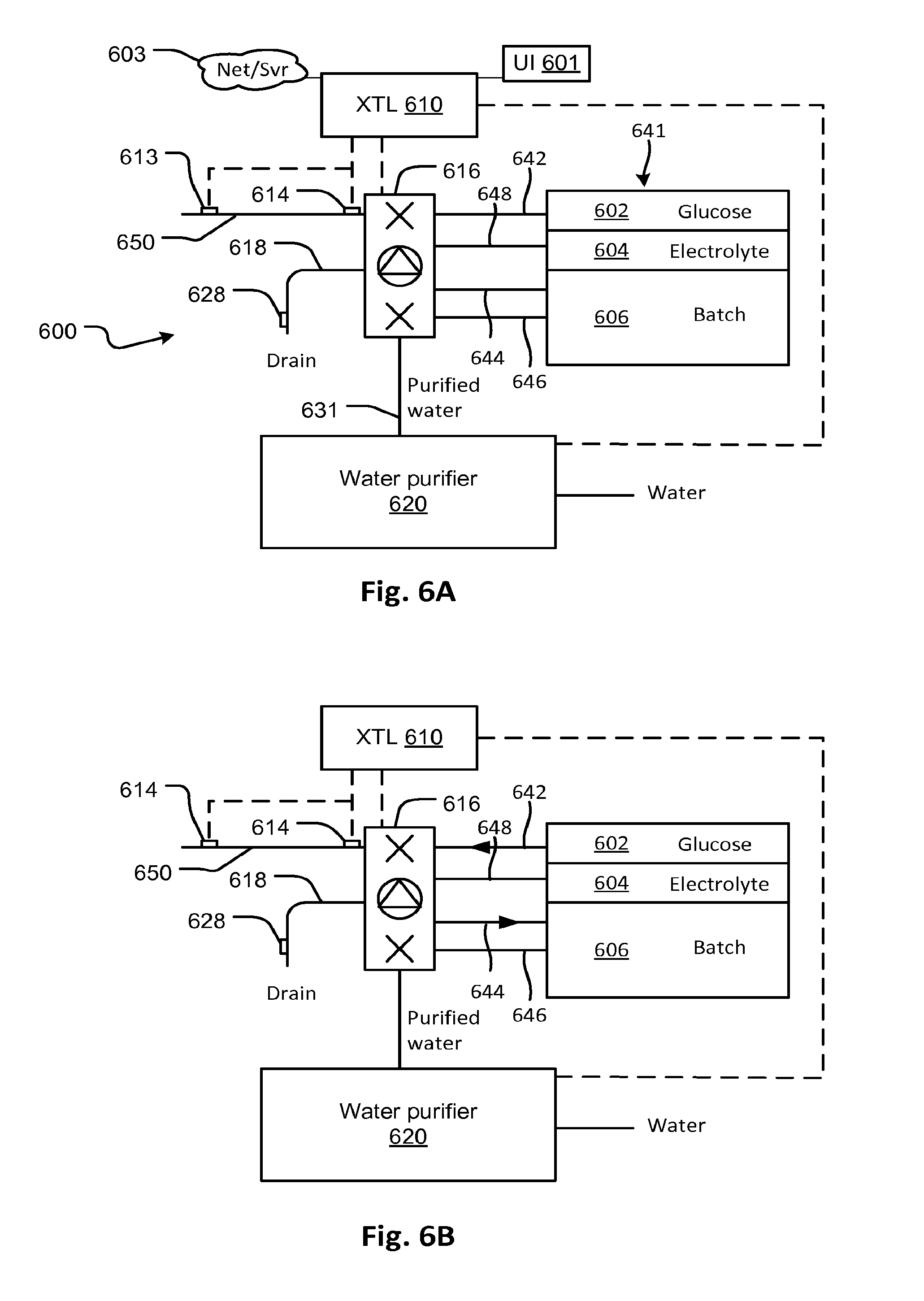
FIG. 6A shows a peritoneal dialysis solution preparation and treatment system according to embodiments of the disclosed subject matter.
FIG. 6B shows the peritoneal dialysis solution preparation and treatment system of FIG. 6A in a first phase of fluid preparation in which osmotic agent is added to a batch container, according to embodiments of the disclosed subject matter.
FIG. 6C shows the peritoneal dialysis solution preparation and treatment system of FIG. 6A in a second phase of fluid preparation in which a dialysate precursor is obtained by dilution and mixing the contents of the batch container, according to embodiments of the disclosed subject matter.
FIG. 6D shows the peritoneal dialysis solution preparation and treatment system of FIG. 6A in a third phase of fluid preparation in which the dialysate precursor properties are verified, according to embodiments of the disclosed subject matter.
FIG. 6E shows the peritoneal dialysis solution preparation and treatment system of FIG. 6A in a fourth phase of fluid preparation in which dialysate precursor is further prepared by addition of electrolyte to the batch container, according to embodiments of the disclosed subject matter.
FIG. 6F shows the peritoneal dialysis solution preparation and treatment system of FIG. 6A in a fifth phase of fluid preparation in which end-use dialysis solution is prepared by adjustment of the dilution of the batch container contents, according to embodiments of the disclosed subject matter.
FIG. 6G shows the peritoneal dialysis solution preparation and treatment system of FIG. 6A in a sixth phase of fluid preparation in which dialysis solution in the batch container is verified, according to embodiments of the disclosed subject matter.
FIG. 6H and FIG. 6K show the peritoneal dialysis solution preparation and treatment system of FIG. 6A in in various treatment modes, according to embodiments of the disclosed subject matter.
FIG. 7A shows a disposable for use with the peritoneal dialysis system of FIG. 6A according to embodiments of the disclosed subject matter.
FIGS. 7B and 7C shows an embodiment of the disposable of FIG. 7A in use on a cycler and fluid preparation device according to embodiments of the disclosed subject matter.
FIG. 8A shows a schematic diagram of a peritoneal dialysis system that generates peritoneal dialysis solution from concentrate according to embodiments of the disclosed subject matter.
FIGS. 8B and 8C show how the valves of a manifold module operate to selectively block and permit the flow of fluid through the manifold module.
FIGS. 8D and 8E show fluid circuit embodiments.
FIG. 9 shows a schematic diagram of a water purifier and with features to support renal replacement therapy delivery systems according to embodiments of the disclosed subject matter.
FIG. 10 shows a schematic diagram of a peritoneal dialysis system that uses pre-mixed dialysate according to embodiments of the disclosed subject matter.
FIG. 11 shows a flow chart describing respective methods for preparing a peritoneal dialysis system for treatment and performing a treatment using either pre-mixed dialysate or concentrate.
FIG. 12 shows a method for fluid circuit priming which may be used in one of the processes shown in FIG. 11 according to embodiments of the disclosed subject matter.
FIG. 13 shows a method for fluid preparation which may be used in one of the processes shown in FIG. 11 according to embodiments of the disclosed subject matter.
FIG. 14 shows a method of pressure testing a sterile filter which may be used in one of the processes shown in FIG. 11 according to embodiments of the disclosed subject.
FIG. 15 shows a method for priming a patient line leading to a patient access, which may be used in one of the processes shown in FIG. 11 according to embodiments of the disclosed subject.
FIG. 16 shows a method for disconnecting and flushing a used fluid circuit which may be used in one of the processes shown in FIG. 11 according to embodiments of the disclosed subject.
FIGS. 17A-17H, 17J-17N, and 17P-17T illustrate steps of preparation for, and termination of, a treatment which may be used in one of the processes shown in FIG. 11 according to embodiments of the disclosed subject.
FIG. 18 illustrates a control system according to embodiments of the disclosed subject matter.
FIG. 19 shows a fluid path and actuator layout according to embodiments of the disclosed subject matter.
DETAILED DESCRIPTION
Referring to FIG. 1, a peritoneal dialysis system 100 includes a peritoneal dialysis (PD) cycler 101 with an internal pump (not shown). The PD cycler 101 pumps dialysis solution from a container 106, such as a bag, or other source, to a patient access 114 through a fill/drain line 112 to a peritoneal catheter 114 into the peritoneum of a patient 108. This happens during a fill cycle.
During a drain cycle, spent dialysate is withdrawn from the patient by flowing in reverse through the fill/drain line back to the cycler 101 and out through a drain 104. The cycler 101 quantifies the volume of fluid that is infused and drained and provides an accounting of the difference to allow the net amount of fluid withdrawn from the patient to be determined.
The pump may be any suitable pump such as a diaphragm pump or a peristaltic pump. Alternatively, the cycler may rely on other fluid conveyance systems such as an over or under-pressurized supply/sump container, gravity feed or any other suitable mechanism.
A controller 116 allows the system to regulate a flow rate to ensure the patient's peritoneal cavity is not over-pressurized. The flow regulation may be accomplished by changing a speed of a pump or by means of a variable flow restrictor or any suitable mechanism conforming to the requirements of the type of fluid conveyance system employed.
Prior art systems have prevented exceeding a safe limit on peritoneal pressure by a variety of mechanisms, including measuring pressure in the fill line using a pressure sensor located on the PD cycler and applying feedback control of the pump to ensure a limit is not exceeded. Another prior art device for preventing over-pressurization of the peritoneal cavity limits the total head pressure by employing a gravitational feed.
An alternative may employ a pressure detection device 110 located at the end of a fill line 112, adjacent the patient 108, or at the access 114 itself, to take pressure readings close to the patient. By using pressure measurements from this location, the error in pressure measurement of the peritoneal cavity due to pressure loss in the fill line during filling of the cavity is eliminated. In this way the flow rate can be controlled by a continuous feedback loop to maintain the cavity pressure below a desired safety threshold. Locating the pressure sensor close to the patient also eliminates another source of error which may arise from a level difference between the supply side of the fill line 112 and the catheter end of the fill line. That is, if the cycler 101 is located higher than the patient access, the gravitational head pressure of the fill line could cause a greater pressure than indicated by a prior art pressure sensor located at the PD cycler which may not otherwise be accounted for, causing excessive pressure to be applied. A low cycler may cause inadequate pressure and slow fill cycles.
In the embodiment of FIG. 1, to provide accurate pressure indication, the pressure detection device 110 is located close to the patient 108 to maximize responsiveness to changes in the peritoneal cavity pressure and minimize the effect of pressure drop due to flow resistance. An electrical pressure transducer may be located at the end of the line. Alternatively, a pressure pod as described in the attached US patent publication 20070179422 may be used. In an embodiment, a pressure transducer may be located at the controller or cycler as shown in FIG. 1 and also at the patient access to measure the pressure of the peritoneal space without the signal bias produced by line pressure drop in the line 112.
FIG. 2A shows a pressure measurement pod 10. In the pod 10, air chamber 45 is in communication with an air port 12 and air line 40 that can be connected to a pressure transducer (not shown). Fluid flows through a fluid chamber 60 between an inlet line 35 connected to an inlet port 70 and out of the fluid chamber 60 through an outlet port 72 into an outlet line 15. The pressure of the fluid in the fluid chamber 60 displaces a diaphragm 25 until the air chamber 45 and fluid chamber 60 are at equilibrium, which is preferably the situation when the air and fluid chambers 45 and 60 are at equal pressure.
The pod 10 is primarily made of two parts, a fluid-side shell 30 and an air-side shell 17, that, together, form an enclosure 5 that defines the fluid and air chambers 60 and 45. The ratio of the minimum to the maximum volume of the air chamber 45, including the volume of the line 40 and port 12, is proportional to the total pressure variation that can be measured by the transducer attached to the line 40.
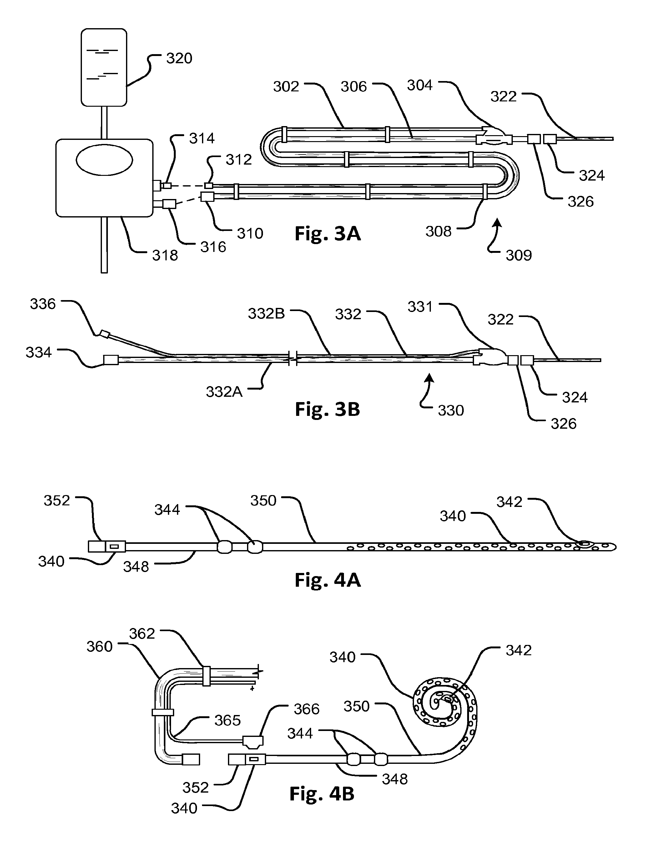
Referring now to FIG. 3A, a fill/drain tubing set 309 has a pod 304 for indicating pressure. The pod 304 may conform to the design of pod 10 of FIG. 2A and may be used to provide a pressure indication at a distal end of a fill/drain line 306. FIG. 3A shows a PD cycler 318 with source of dialysate 320 and connectors 316 and 314 for the fill/drain line and a pressure sensing line 302, respectively. The pressure sensing line 302 connects a pressure transducer (not shown separately) on the PD cycler 318 to the pod 304 to permit the transducer to read the pressure exerted on the diaphragm (not shown in FIG. 3A) of the pod 304. The pod 304 is connected directly to the fill/drain line 306 in an inline configuration and close to an access connector 326 to which a peritoneal catheter 322 can be connected by connector 324. The pressure sensing line 302 is attached to the fill/drain line 306, for example by a series of connectors 308, so that it runs parallel along the fill/drain line 306. The PD cycler 318 may also be provided with an additional pressure sensing device forming part of a fluid circuit to which the fill/drain line 306 is attached and configured to measure the pressure in the fill/drain line 306 close to the PD cycler 318.
Thus, in the present embodiments, the pressures at each end of the fill/drain line 306 may be determined by a controller that operates the cycler at all times during operation of the PD cycler 318 and applied as continuous input signals to the controller during fill and drain operations. As discussed below, these inputs can be used to allow the capture and storage of vital signs, detection of flow restrictions and kinks in the fill/drain line 306, and allow the regulation of flow rate while managing the pressure within the peritoneum.
FIG. 2B shows a peritoneal dialysis tubing set 60 with an integrated pressure sensor 45 located at a distal end of a fill-drain line 47. The fill-drain line may have one or two lumens for shared or separate fill and drain use, respectively. A pressure transducer 45 is in pressure communication with a lumen of the fill-drain line 47. If there are separate fill and drain lumens, each may carry its own pressure transducer 45 or only one, for example, the fill line, may carry a pressure transducer 45. The transducer may be, for example, a strain gauge component that reacts to isotropic pressure (e.g. fully wetted and immersed) or it may be a strain gauge component built into the wall of an inline fluid conveying component. Other configurations are also possible to achieve the effect of providing pressure sensing at the distal end of the fill-drain line 47. A pair (or more, as necessary) of conductors 48 run along the length of the fill-drain line 47 to connect to an electrical connector 50 which connects to a driver circuit 51. The driver circuit may contain a power supply and reader circuit or other suitable circuitry for generating a pressure signal from the pressure applied by fluid in the lumen of the fill-drain line 47 at its distal end. A connector 46 configured for connection to a peritoneal catheter is attached to the distal end and a connector 49 for connection to a source and/or sink of fluid is located on the proximal end of the fill-drain line 47. The connector 46 may be permanently attached to a peritoneal catheter or may have a peritoneal catheter preinstalled thereat. The connectors 49 and 46 may be sealed to isolate the lumen and the unit 60 delivered as a sealed unit with a sterile lumen.
Referring now to FIG. 3B, a variation of a fill/drain line tubing set 330 similar to the embodiment 309 of FIG. 3A has a double tube 332 with fill/drain line portion 332A having a large diameter lumen on one side and pressure line portion 332B having a small diameter lumen 332B on the other side. Both lumens run the entire length of the fill/drain tubing set 330. Connectors 334 and 336 are provided at proximal end for connecting the fill/drain line side 332A lumen and the pressure line side 332B lumen to a fluid circuit and pressure sensor respectively. A pressure pod 331 is connected to convey pressure signals through the small lumen of the pressure line side 332B. The pressure pod 331 is connected inline with the fill/drain lumen such that pressure is applied to an internal diaphragm indicating pressure at the distal end of the fill/drain lumen. Note that the fill/drain tubing set 330 may be formed in various ways, for example by welding two tubes together or by extruding the two tubes with an integral web between them. Mating connectors 326 and 324 may be provided for connecting a peritoneal catheter 322.
The embodiment of FIG. 3B may be used in the same manner as that of FIG. 3A. Thus, in this embodiment also, the pressures at each end of the fill/drain line may be determined by a controller that operates the cycler at all times during operation of any suitable PD cycler and applied as continuous input signals to the controller during fill and drain operations.
Referring now to FIGS. 4A and 4B, a peritoneal catheter 350 has an integrated pressure transducer 342 which is connected by embedded electrical leads 340 running along the catheter 350 to a terminal connector 340. A pair of cuffs 344 is located on a proximal section 348 near the proximal end which is provided with a fluid connector 352. The pressure transducer 342 may be a strain gauge device with a flexible hermetic wrapper that can be welded to the catheter or integrally molded in. The connector 366 may be of any suitable type and may be connected a lead 365 carried on a fill/drain tubing set 360 similar in design to that of FIG. 3A (or that of FIG. 3B or any other suitable design). The lead 365 may have suitable mating electrical connectors for connection to a cycler with a controller to apply a pressure signal from the transducer 342. The catheter 350 has openings to distribute outflow and suction in the peritoneal cavity as in known catheters for peritoneal dialysis.
A variation of any of the foregoing embodiments may be fill/drain lines with separated fill and drain lines, each having a respective lumen. The lines may be connected to the cycler by separate attachments, merged by a T or Y junction at the cycler, merged at the peritoneal catheter or a combination of these.
Referring now to FIGS. 5A to 5C, an example process for monitoring pressure signals from the foregoing peritoneal devices is now described. FIG. 5A shows a process for storing a string of pressure signal samples for an interval of time. For example, the pressure signal may be sampled at 100 ms intervals for a period of 20 seconds at S12 and the process repeated after a delay S10. The samples may be stored in a memory for many samples covering an entire treatment or for only a portion of a treatment. Alternatively to the process of FIG. 5A, pressure data samples respective of each pressure sensor may be continuously stored in a memory and refreshed after archiving following a treatment or refreshed in a first-in first-out fashion according to a time interval so as to preserve only a short term historical record. In another alternative, only instantaneous pressure data may be stored.
The procedure of FIG. 5B derives various information from the data stored by the operation of FIG. 5A. The operation may be applied to each pressure signal, including, for example, those provided by a distal pressure sensor (e.g., 110 of FIG. 1) and a proximal pressure sensor (e.g., 102 of FIG. 1). The procedure of FIG. 5A recovers the stored signal segment S22 and processes it to remove noise S24 (e.g. low pass filtering, smoothing, thresholding or other suitable filtering process). At S26, the pressure signal segment is analyzed to generate a reliability metric indicating its accuracy. The latter may be done in various ways, for example, by identifying differences between a stored actual reading and a measured pressure or rate of change in pressure. In addition, or alternatively, the goodness of fit of the pressure profile to a stored model may provide a measure of accuracy (the curves being fitted in S28). The pressure reading may be compared to a profile. In S28, pressure profile data is translated into a respiration rate and pulse rate by fitting expected respiration and pulse curves to the stored data and the reliability metric and analyzing.
More sophisticated analysis may be done in S28 as well, for example, by fitting the measured data curves to curves that characterize identifiable conditions, such as dangerous conditions. For example, a leak may be indicated by a sharp drop in pressure at the distal location along with a gradual trend of ebbing pressure. The profile templates that characterize events may be may be determined via experiment or modeling or simply by judgment and stored in a memory of the controller. Other events that may be identified, for example by comparing distal and proximal pressure readings, are kinks or flow restrictions in the fill/drain line or changes in the properties of fluid, for example such as may evidence peritoneal infection. The latter may be detected by identifying an excessive pressure drop in the fill/drain line during a drain operation, which may be caused by excessive viscosity in the spent dialysate.
In S30, events detected in the profile data, current pressure values, historical data, and reliability estimates are updated. Current data, for example, may be stored in a location representing current values and historical data may be stored in memory locations representing historical values along with time and date values. For example, a memory location may hold a current estimate of patency of the fill/drain line. The event detection results may be represented as status flags and associated reliability estimates or other metrics such as a measure of goodness of fit to a characteristic curve or instantaneous value.
Referring to FIG. 5C, during a fill or drain cycle S42, the event recognition status and/or instantaneous values, such as those of pressure, are read by the controller from the controller memory S44 and compared to various threshold levels S46, S48, S50 and if the threshold test is met, an alarm indication may be generated S52 and the cycler may be placed in a safe mode corresponding to the detected event or condition. Otherwise, control may return to S42.
Archived data may be transferred to a data store for combination with data of multiple patients, for example via an internet connection, for analysis and comparison purposes.
The conditions detected in S46, S48, S50 may include, for example: 1. A reduction in the strength of vital signs (e.g., respiration, pulse) signal evidencing a line obstruction, loss of patency of the catheter or other problem; 2. Excessive pressure loss for an instantaneous flow rate, which may indicate a line obstruction, kink, or pinching of the line or other problem; 3. Excessive pressure of the peritoneum which may be compensated by reducing or stopping the flow rate; 4. Excessive drain flow pressure loss in the drain line due to high viscosity which may indicate an infection.
Referring now to FIG. 6A, a peritoneal cycler system 600 generates custom peritoneal dialysis solution according to a prescription stored in a controller 610. The prescription may be entered in the controller via a user interface 601, via a remote terminal and/or server 603 or by other means such as a smart card or bar code reader (not shown). The controller applies control signals to a fluid conveyer and circuit switch 616 and a water purifier 620 and receives signals from distal and proximal pressure sensors 613 and 614, respectively, on a fill/drain line 650 which may be in accord with foregoing embodiments.
The fluid conveyor and circuit switch 616 is a fluid circuit element with one or more sensors, actuators, and/or pumps which is effective to convey fluid between selected lines 642, 644, 646, 648, 650 and 618 responsively to control signals from the controller 610. Example embodiments are described herein, but many details are known from the prior art for making such a device so it is not elaborated here.
A multiple-container unit 641 includes a pre-filled, pre-sterilized osmotic agent container for osmotic agent concentrate 602 and another electrolyte container with electrolyte concentrate 604. The unit 641 also contains an empty batch container 606 which is large enough to hold a sufficient volume of dialysis solution for the completion of at least one fill cycle of an automated peritoneal dialysis treatment. The containers 602, 604, and 606 may be flexible bag-type containers that collapse when fluid is drawn from them and therefore, do not require any means to vent air into them when drained.
Osmotic agent container 602, electrolyte container 604, and batch container 606 are all connected by respective lines 642, 648, 644, and 646 to the fluid conveyor and circuit switch 616. The fill/drain line (or multiple lines) 650 and a spent fluid drain line 618 with a conductivity sensor 628 may also be connected to the fluid conveyor and circuit switch 616. The fluid conveyor and circuit switch 616 also has a fill line 631 for receiving water. The water purifier 620 may be a purifier or any source of sterile and pure water including a presterilized container of water or multiple containers. In a preferred configuration, water purifier 620 may be configured as described in WO2007/118235 (PCT/US2007/066251) hereby incorporated by reference in its entirety and attached to the provisional application. For example, the water purifier 620 may include the flow circuit components of FIG. 22 including the water purification stages and conform generally to the mechanical packaging design shown in FIG. 24 of the incorporated (attached) publication.
FIG. 6B shows a preliminary stage of fluid preparation prior to treatment according to an embodiment of the disclosed subject matter. The controller 610 reads a prescription and generates a command, responsive to a treatment preparation initiation command, to flow osmotic agent concentrate from container 602 to the batch container 606. The command is applied to the fluid conveyor and circuit switch 616 to connect the osmotic agent concentrate line 642 to the batch fill line 644 and also to convey the osmotic agent concentrate into the batch container 606. This may be done by one or more valve actuators and one or more pumps that form the fluid conveyor and circuit switch 616. The fluid conveyor and circuit switch 616 may be configured to meter the quantity of osmotic agent precisely according to a predicted amount of dilution by electrolyte and water to achieve the prescription. The metering may be performed by a positive displacement pump internal to the fluid conveyor and circuit switch 616 or other means such as a measurement of the weight of the osmotic agent container 602 or the batch container or a volumetric flow measurement device.
In an alternative embodiment, part of the water (less than the total used for dilution as discussed below with reference to FIG. 6C) is added to the batch container first, before the osmotic agent and electrolytes (if needed) are pumped into the batch container.
Referring now to FIG. 6C, a dilution stage is performed using the peritoneal cycler system 600. The controller 610, in response to the prescription, generates a command, to flow purified water from the water purifier 620 to the batch container 606. The command is applied to the fluid conveyor and circuit switch 616 to connect the purified water line 631 to the batch container 606 to add a measured quantity of water to dilute the osmotic agent concentrate in the batch container 606. The controller may control the fluid conveyor and circuit switch 616 to ensure the correct amount of water is conveyed. Alternatively, the water purifier may incorporate a flow measurement device or metering pump or other suitable mechanism to convey the correct amount of water. The controller 610 may be connected to the water purifier 620 to effectuate the dilution result. The fluid conveyor and circuit switch 616 may also be configured to circulate diluted osmotic agent solution through lines 644 and 646 either simultaneously with the dilution or after the diluting water has been transferred to the batch container according to alternative embodiments.
The relative amounts of water, osmotic agent, and electrolyte may be defined based on the ratiometric proportioning properties of the pump. Since a single tube is used to convey all the liquids into the batch container, most sources of offset from predicted pumping rate (based on shaft rotations, for example) to actual pumping rate affect all the fluids roughly equally.
Referring now to FIG. 6D, the diluted osmotic agent solution in the batch container 606 is tested to ensure the correct concentration of osmotic agent is achieved. In an embodiment, the osmotic agent concentrate 602 has an amount of electrolyte concentrate to generate a conductivity signal using the conductivity sensor 628 when fluid from the batch container 606 is conveyed by the fluid conveyor and circuit switch 616 to the drain line 618 past the conductivity sensor. The amount of electrolyte pre-mixed with the osmotic agent may be lowest ratio of electrolyte to osmotic agent a possible prescription may require. The fluid conveyor and circuit switch 616 may perform the function using one or more valve actuators and one or more pumps that form the fluid conveyor and circuit switch 616. The fluid conveyor and circuit switch 616 may be configured to meter the quantity of water precisely or the function may be provided by the water purifier 620. The controller may add additional water or osmotic agent and test the conductivity again if the measured concentration of osmotic agent/electrolyte is incorrect. In addition to using a combined osmotic agent and electrolyte concentrate in osmotic agent container 602, in an alternative embodiment, the osmotic agent container 606 holds osmotic agent concentrate with no electrolyte and osmotic agent concentration is measured directly by other means such as specific gravity (hydrometer), refractive index (refractometer), polarization, infrared absorption or other spectrographic technique.
FIG. 6E shows an electrolyte addition stage of fluid preparation prior to treatment according to an embodiment of the disclosed subject matter. The controller 610 reads a prescription and generates a command to flow electrolyte from container 604 to the batch container 606. The command is applied to the fluid conveyor and circuit switch 616 to connect the electrolyte concentrate line 648 to the batch fill line 644 and also to convey the electrolyte concentrate into the batch container 606. This may be done by one or more valve actuators and one or more pumps that form the fluid conveyor and circuit switch 616. The fluid conveyor and circuit switch 616 may be configured to meter the quantity of electrolyte precisely according to a predicted amount of dilution by osmotic agent and water that has been previously determined to be in the batch container 606, to achieve the prescription. The metering may be performed by a positive displacement pump internal to the fluid conveyor and circuit switch 616 or other means such as a measurement of the weight of the electrolyte container 604 or the batch container 606 or a volumetric flow measurement device.
Referring now to FIG. 6F, the electrolyte may be mixed using the batch fill and drain lines 646 and 644 in a closed loop. If necessary, depending on how much dilution was performed during the osmotic agent dilution process, further dilution may be performed as described above. The final formulation may be achieved by the process illustrated in FIG. 6F. Then, as illustrated in FIG. 6G, the final electrolyte concentration of the mixture in batch container 60 may be determined with a conductivity sensor 628 by flowing a sample therethrough.
In addition to mass or conductance measurements, other types of measures may be used to measure proportions of dialysis fluid components and dilution. For example, tracer chemicals such as radioactive tracers or dyes may be used.
Although gravimetric and tracer/conductance sensing were described as devices for ensuring proper proportioning and dilution rates for achieving target prescriptions, it should be clear that the system may employ ratiometric proportioning as well, particularly where positive displacement pumping is employed. Ratiometric proportioning takes advantage of the volumetric repeatability and predictability of certain pumps. For example, a particular pump can deliver a highly repeatable volume of fluid for a given number of pumping cycles (pump rotations for a peristaltic pump or cycles for a diaphragm pump, for example). If all dialysis solution components (water, osmotic agent concentrate, and electrolyte concentrate, for example) are delivered to the mixing container using the same pump, including, for example, the pumping tube segment of a peristaltic pump, then the volume ratios of the components will, after adjustment for potential flow path and/or viscosity differences as described below, be fully determined by the number of pump cycles used to convey each component.
This proportioning may supplement or substitute for measurement of the fluid conductance or density or other measurements. To convert the number of pump cycles to actual displaced mass or volume, a calibration may be performed and/or flow path (including fluid properties) compensation parameters may be employed. The flow path compensation parameters may be respective to each particular fluid flow path and/or fluid type, or may be identical for all fluid paths and fluid types. To provide enhanced accuracy, one or more pump calibration and/or flow path compensation parameters may be generated through a calibration procedure. Typically, flow path compensation factors will be established during the development of the system and stored in non-volatile memory. Typically, one or more flow path calibration procedures will be performed when the system is used by a patient. The calibration procedure may be performed after each new fluid set is installed, or before each batch preparation cycle, or even multiple times during the preparation of a single batch. A disposable fluid set may be installed every day. The calibration procedure may be done using water. The calibration may sequentially pump fluid through one or more of the following stages:
TABLE-US-00001 From To Water source Drain Batch container Drain Osmotic agent concentrate Drain container Electrolyte concentrate Drain container Patient access Drain Batch container Patient access Osmotic agent concentrate Batch container container Electrolyte concentrate Batch container container Water source Batch container
In the calibration procedure, fluid is pumped between any or all of the paths identified above. A separate calibration coefficient may be generated for each of the paths. The calibration coefficient may be stored in a memory or non-volatile data store, for example, as a parameter representing the number of ml/per pump rotation (or diaphragm pump cycle), or as a proportionality ratio relative to a particular reference flow path. The actual fluid quantity transported during the calibration step may be measured by any suitable device (flow sensor) including volume or mass measurement devices or direct flow rate measurement with integration, for example, using laser Doppler velocimetry, thermal transit time, magnetohydrodynamics, propeller hydrometer, positive displacement flow measurement, differential pressure through a resistance such as a venturi, nozzle, orifice plate, or other flow obstruction, variable area or rotameter, pitot or impact tube, vortex shedding frequency counting, ultrasonic, or other device. Any of the disclosed embodiments may employ a flow sensor in which at least the portion of which that carries fluid is disposable so that the flow rate (or total displaced fluid quantity) can be input to a controller while allowing the use of a disposable fluid circuit. Examples include an ultrasonic soft tube flowmeter made by Strain Measurement Devices SMD that non-invasively measures flow in soft tubing by means of slotted transducers in which a length of tubing can be inserted during fluid circuit installation. For cartridge embodiments, the PD cycler can employ a moving transducer stage that engages an exposed tube length of the cartridge after passive insertion of the cartridge.
The pumping system may also be sufficiently repeatable in a way that allows precise ratios to be established without calibration, depending on the predefined tolerances chosen by the system designer. If the manufacturing tolerances, including materials, are sufficiently controlled, a desired level of control over ratios may be achieved without in situ (point of care) calibration. A particularly sensitive component in terms of guaranteeing repeatability is the pumping tube segment of a peristaltic pump. In a first embodiment, the peristaltic pump tube segment is made from a material whose mechanical and material tolerances are controlled within predefined limits. The lengths of the tubing circuit elements and mechanical parameters are also controlled within respective predefined limits. A calibration may then be done outside the treatment context, e.g., in the laboratory, to calculate precise values to convert pump cycles to fluid quantity transferred for a single lot of replaceable fluid circuits. The calibration may be done for multiple lots. The calibration may also be done for each fluid circuit. The calibration may also be done by the treatment system for each fluid circuit. The calibration may also be done for each batch of fluid prepared by the fluid circuit.
Referring to FIG. 6H, subsequent to the preparation of the contents of the batch container 606 as described above, the fluid conveyor and circuit switch 616 may be configured to drain the patient 611 depending on the patient's prior status. Spent dialysate fluid may be withdrawn by the fluid conveyor and circuit switch 616 and conveyed through the drain line 618. Then, the contents of the batch container 606 may be conveyed as illustrated in FIG. 6K to the patient. Here the controller 610 has configured the fluid conveyor and circuit switch 616 to flow fluid to a patient 612.
Referring now to FIG. 7A, a fluid circuit embodiment for implementing the embodiment of FIG. 6A includes a disposable fluid circuit 700. The fluid circuit 700 may include pre-attached osmotic agent and electrolyte concentrate containers 760 and 762. Also, the fluid circuit 700 may include pre-attached batch container 764. The contents of the osmotic agent and electrolyte concentrate containers 760 and 762 may be sufficient for multiple cycles and thereby cover a complete automated peritoneal dialysis treatment. The internal volume of the batch container may be sufficient for one cycle or multiple cycles in a single automated peritoneal dialysis treatment.
The fluid circuit 700 is preferably a disposable unit that has a completely sealed internal volume except for a water inlet connection 730 for connection to a source of purified water, a drain connection 713, and a connection for a patient access 717. The connectors 730, 713, and 717 may be sealed with a removable connector cap and the entire disposable fluid circuit 700 sterilized as a unit. The water inlet line 726 may include a sterile barrier 728 in the form of a sterile filter, for example, one with a pore size of 0.2 microns or smaller to filter out contaminants. Effectively, that leaves only the patient access connection 717 and the drain connection 713 as possible entry paths for contaminants. However, the drain line 712 can incorporate a check valve to prevent inflow of fluids therethrough. It is generally a one-way path as well, so this removes all but the patient access connection 717 as a possible route for contaminants to flow into the sealed volume of the fluid circuit 700.
The fluid circuit 700 includes fluid circuit manifold panels 702 and 704 which each distribute flow along their respective lengths effectively allowing flow between any of the connected respective lines. For example, fluid from the osmotic agent line 724 can flow into the manifold 702 and be pumped through a pump line 706, which is configured to mate with a peristaltic pump, into the manifold 704 and then into a selected one or more of the mixing line 715, drain line 714, and/or fill/drain line 716. The fluid circuit manifolds 702 and 704 may include sensor regions (not indicated).
A variety of alternative manifold and/or actuation devices can be used to implement the methods described herein. For example, referring to FIG. 8D, a fluid cartridge 800 has two shell parts 802 and 803 that partially enclose a tubing set with manifold branches 806 (typ.) that stem from manifold parts 812A and 812B. Windows 810, 805 in each shell part 802 and 803 appear in pairs on either side of a branch 806 to permit a linear actuator (solenoid clamp, stepper and screw drive, pinching mechanism like a plier grip, or other kind of mechanism) to access, and selectively clamp, the segment 816 from outside the shell.
The shell housing is assembled as indicated by the dotted arrows into a partial enclosure. Alternatively the tubing parts and manifold may be attached to a single backplane or inserted in a support on a permanent mounting fixture of a PD cycler.
A window, provided by openings 804 and 815, similarly provides access to a pump tubing segment 816 by a peristaltic pump rotor. The pump tubing segment 816 may be flanked by, and also be size-matched to connected tubing, by pressure pods 814. Pressure pods for fluid pressure measurement are known in the art and the details are not provided herein.
The manifolds of the foregoing figures can be realized using a variety of structures. For example, fluid circuit part 826 uses Y-junctions 828 and connecting segments 827 to interconnect tubing branches 828. This structure may be used in place of manifold part 812B, for example, and a variation for manifold part 812A.
The completed device 800 may form a fluid cartridge that can inserted in a cycler housing like a slice of bread in toaster or may be attached to the actuators in other ways.
Actuator regions 732A-732H allow the selective closing of connections to a respective line such as drain line 716. This allows any of the lines connected to manifold 702 to be connected to a line of manifold 704 through the pumping line 706 by closing all the other lines except the selected lines. In manifold 704, actuator region 732A controls access to patient access line 716. Actuator region 732B controls access to drain line 714. Actuator region 732C controls access to mixing line 715. In manifold 702, actuator region 732D controls access to batch fill line 718. Actuator region 732E controls access to drain line 718. Actuator region 732F controls access to electrolyte fill line 722. Actuator region 732G controls access to osmotic agent fill line 724. Actuator region 732H controls access to the water fill line 726.
The patient access line may include a pressure sensor 735 such as a pressure pod as described above with an air line 734 and a connector 736 for connection to a pressure transducer on a peritoneal dialysis cycler or, alternatively, to a sensor region on the fluid circuit manifold.
Referring now to FIG. 7B, a combined fluid preparation apparatus and PD cycler 788 is combined with a water purifier 790 forming a PD system 701. A disposable fluid circuit unit 758 conforms to the general description of the embodiment 700 of FIG. 7A. An automated peritoneal dialysis cycler 788 has a control panel 776 and is configured to use the disposable fluid circuit 758. Various actuators and sensors (e.g., pressure transducers, temperature sensors, optical leak detectors, etc. are generally indicated at 772. A hatch 773 may be closed over the disposable unit cassette 758 to bring the components thereof into engagement with the various actuators and sensors 772.
The disposable fluid circuit unit 758 has a cassette portion 766 that incorporates manifolds 762 and 764 (corresponding respectively to manifolds 702 and 704 of FIG. 7A). The manifolds 762 and 764 are attached to each other but have internal flow areas that are not in fluid communication (isolated from each other) so that only a pump line 768 allows fluid communication between the manifolds 762 and 764. The other elements of the fluid circuit 758 are as described with reference to FIG. 7A. The automated peritoneal dialysis cycler 788 is shown set atop a water purifier 790. The automated peritoneal dialysis cycler 788 may include a tray 780 for supporting the batch container 764 and/or a scale 778 for measuring its weight. A support 782 supports the osmotic agent and electrolyte containers 760 and 762, respectively.
A registration area 770 (for example a recess area) of the automated peritoneal dialysis cycler 788 has a peristaltic pump actuator 774. The registration area receives the cassette portion 766 of the disposable fluid circuit unit 758 as shown in FIG. 7C so that the pump line 768 engages the peristaltic pump actuator 774 and the sensor and actuator areas of the cassette engage the corresponding sensors and actuators 772 of the automated peritoneal dialysis cycler 788.
Referring now to FIGS. 8A and 9, schematic diagrams of a peritoneal dialysis system 900 and water purification system 901 are shown which operate together as a complete system as described in the present specification. The peritoneal dialysis system 900 includes a fluid management set 900A. The fluid management set 900A is coupled to a fluid circuit of the water purification system 901 which contains a permanent module 952 and consumable components including filter media and tubing sets 901A. The peritoneal dialysis system 900 includes a PD cycler and dialysate preparation module 949 which contains controls and much of the permanent hardware; the water purification system may be interconnected to share controls so that a single user interface panel 906 may be used to control both for administration of treatment.
The PD cycler and dialysate preparation module 949 has a controller 907 with a user interface panel 906. The user interface panel has controls 906A, 906B, 906C and a display 906D. The controls and other features of the user interface panel 906 may include an audio output device, LED lamps, touchscreen input, and other devices that may be employed for interacting with digital electronic control systems. Preferably the user interface panel 906 controls 906A, 906B, 906C are a small set of clearly differentiated controls that are color coded and shape-differentiated.
The fluid management set 900A includes disposable batch, electrolyte, and osmotic agent concentrate containers 908, 910, and 912, for example, bags that are connected to respective dialysis solution, electrolyte, and osmotic agent draw lines 916, 915, 914. The batch container 908 is preferably an empty presterilized flexible container that is delivered empty of air or fluid and permanently attached to the dialysis solution draw line and a batch fill line 917, the batch fill line 917 being used to add fluid to the bag and the dialysis solution draw line 916 being used to draw contents from the bag. Electrolyte and osmotic agent concentrate containers 910 and 912 store, respectively, electrolyte and osmotic agent concentrate and are also permanently attached to osmotic agent and electrolyte draw lines 914 and 915. The containers and lines are preattached and provided in a sterile condition. The batch container 908 is eventually filled with a mix of sterile water, osmotic agent and electrolytes to form a dialysis solution prescription. The batch container 908 has two lines while the other containers have a single line. The osmotic agent and electrolyte containers 912 and 910 may be fitted with non-reopening clamps 953.
The batch container 908 may be configured to accommodate sufficient dialysis solution for a single peritoneal dialysis fill cycle or it may be large enough for multiple fill cycles. Thus a preparation cycle may generate enough dialysate for a complete treatment (for example a nocturnal treatment cycle including multiple drain-fill cycles).
The batch, electrolyte concentrate, and osmotic agent concentrate containers 908, 910, and 912 may rest on a heater and/or scale 902 indicated by dashed lines. Temperature sensors 904 and 905 may be provided on the surface of the heater and/or scale 902 to provide temperature signals to the controller 907, which controls the heater and/or scale 902. The controller may be configured to warm the dialysate in the batch container 908, which rests directly on the heater and/or scale 902. The temperature sensors 904 and 905 may be positioned to ensure the batch container 908 rests directly on the temperature sensors 904 and 905. The combination of free convection in the large batch container 908 (multiple liters), thin wall of the batch container 908, and the compliance of the wall help to ensure a reading of the temperature sensors 904 and 905 that reflects the temperature of the contents of the batch container 908. Note while the temperature sensors 904 and 905 are shown positioned remote from the batch, electrolyte, and osmotic agent containers 908, 910, 912, it is intended that they be located immediately adjacent to the batch container 908.
The draw lines 914, 915, and 916 and the fill line 917 connect to a manifold module 911 with two valve headers 941 and 946, separated by a barrier section 842, and interconnected by a pump tubing segment 944. The flow between the valve headers 941 and 946 occurs only through the pump segment 944 or through an external connection between the lines linked to it, such as by flowing through the batch container 908 via the valve headers 941 and 946 draw and fill lines 916 and 917. The manifold module 911 in combination with a peristaltic pump actuator 943 and valve actuators 929, 930, 928, 931, 932, 933, 934, and 935 provides and regulates the flow of fluid between selected pairs of the tubing lines 914, 915, and 916, the fill line 917, drain lines 920A and 920B, product water line 919 and a patient line 945. The manifold module 911 also has sensor regions 936 and respective pressure transducers 924 and 925 to generate pressure signals reflecting pressure on either side of the pump tubing segment 944.
The manifold module 911 also has chambers 913A and 913B and respective pressure transducers 926 and 927 to generate pressure signals reflecting pressure on proximal and distal ends of the patient line 945. The pressure chamber 913B is connected to a pneumatic signal line 909 which is in turn connected to a pressure pod 951 configured to transmit the pressure in the patient line 945 distal end through the pneumatic signal line 909 to the chamber 913B. Chamber 913A is in communication with the end of the patient line 945 that is closest to it and conveys the pressure to the transducer 926 to generate a signal representing the pressure at the proximal end of the patient line 945. The controller 907 is connected to control the peristaltic pump actuator 943 and valve actuators 929, 930, 928, 931, 932, 933, 934, and 935 and receive pressure signals from the pressure transducers 924 through 927. The manifold module 911 may be pressed against the valve actuators 929, 930, 928, 931, 932, 933, 934, and 935 by means of a door 973 which may have a hinge and latch as shown in the figures.
An alternative embodiment has a direct pressure-to-electrical transducer in place of the pressure pod 951, which obviates the need in such embodiment for chamber 913B. A direct pressure-to-electrical transducer may take the form of an immersible strain gauge which is bulk-mode deformable so as to provide negative and positive pressure values or either one as required. An electrical lead or wireless channel may convey a pressure signal to the controller 907. Such a transducer may be integrated into a connector for the patient access. Alternatively, the direct pressure-to-electrical transducer may be a pressure catheter, such as one integrated with the peritoneal catheter, as described elsewhere in the present document.
The manifold module 911 has respective box shaped valve headers 941 and 946. Each header has a plurality of valve structures that is actuated by a respective one of the valve actuators 929, 930, 928, 931, 932, 933, 934, and 935. The valve actuators 929, 930, 928, 931, 932, 933, 934, and 935 may be solenoid hammers, linear motors, pneumatic hammers or any suitable device for applying a force to press on a respective one of the header valves (one of the valves being indicated at 140). Referring to FIGS. 8B and 8C, a valve 140 is shown in an open position (FIG. 8B) and a closed position FIG. 8C). The plunger 136 of an actuator (such as 929) moves vertically to exert a force on a membrane 134 to close it over an opening 132. A tube 131 is attached by bonding to the header wall 135 using a conforming port 133 to allow the tube 131 to be received and sealed to the header wall 135. The tube 131 is sealed to the header wall 135 preventing flow between a lumen of the tube when the membrane is closed over the opening 132. An interior volume 130 of the valve header 941 or 946 is thereby only accessible selectively by operating the actuator to drive the plunger 13 accordingly. By selecting a pair of actuators to open, flow can occur through the interior volume of the valve header between the lumens of two tubes corresponding to the pair of actuators that are activated to open. The actuators can be normally closed by a spring (or other means) and only opened when the actuator is energized. Alternatively they can be normally open.
The product water line 919 connects to a water purification system (line continues to a line labeled with the same joining symbol A in FIG. 9). The drain line 920 connects to the water purification system (the line continues to a line labeled with the same joining symbol B in FIG. 9. A control line connection (which may be wired or wireless) indicated by connection symbol C may be provided to connect an internal central controller 959 to the controller 906 to permit commands from the controller 906 to be used for controlling the water purification system 901. Note that alternatively, instead of a controller 959, a data bus or equivalent communication network such as a wiring harness or wireless piconet (not shown) may give direct access to all sensors and final controllers and actuators of the water purification system 901 to the controller 906 so that the water purification system is simply a component of the peritoneal dialysis system 900. In other embodiments, the water purification system is operable as a stand-alone device and includes its own user interface and control to supply product water for other functions such as hemodialysis. In embodiments, the functions of user interface 906 may be incorporated or included in wireless input devices such as a scale 955 or a portable user interface module 956.
A sterile filter 939 is provided to sterile-filter product water provided in product water line 919. During, prior to, or after preparation of a batch of dialysis solution, the filter may be tested for leaks by performing a bubble point or pressure decay test. A delta-pressure transducer (two pressure sensors separated by the membrane) or a single pressure transducer on the air side of a wetted membrane. In the present embodiment, a transducer at 919 measures the pressure in an air chamber 948 which is in communication with an air side of a wetted membrane of the sterile filter 939. The pressure transducer 919 is used to detect pressure decay (or in other embodiments, a transmembrane pressure TMP decay profile) to determine if the filter integrity is within expected limits. In the present embodiment, an air pump 917 draws air through a filter 921 and selectively pumps it through a control valve 923 and a pressure sensor. The pump 917 may run continuously using a pressure regulated valve 918 to maintain a desired pressure supply to the valve 923 and the valve 922 which may be opened selectively to deliver air into chamber 913B and/or 948. The purpose of flowing air into chamber 948 is to perform a bubble or pressure decay test which is done after making a batch of dialysis solution and to confirm that the filter integrity was maintained during transfer of product water. The flowing of air into chamber 948 is done for the purpose of resetting the volume of the air-side chamber of the pressure pod 951. Air may be selectively leaked from and pumped into the pressure pod to avoid the diaphragm being pinned against one side or the other of its range of travel thereby preventing false readings. So to summarize, valves 918, 923, and 922 are controlled by controller 907 to regulate pressure (by bypassing flow), and selectively allow air to flow to chambers 913B and/or 945 for the described functions.
Referring now particularly to FIG. 9, the water purification system 901 purifies water through a first stage employing a coarse particular and/or sediment trap 994. A second stage employs a carbon filter. A third stage uses an ultraviolet lamp to decontaminate water. A fourth employs reverse osmosis. A fifth stage uses a carbon polishing filter which is followed by a sixth stage of deionization filtration. A seventh and final stage is a sterilization stage employing a pair of ultrafilters connected in series, which prevents grow-through contamination of the final product water, is provided. '901
A permanent filtration subsystem 952 contains a pump, 990 the ultraviolet lamp 982, sensor modules 984 and 985, automatic shutoff valve 988 for the reverse osmosis system, pressure sensors 992, 981, 953, 989 and valves 991 and 993.
Drain fluid from drain line 920 passes through a connector 978 and into a pair of sensor modules 984 and 985 which detect and measure conductivity and temperature, respectively. The sensor modules 984 and 985 provide redundancy as a protection against an error in one of the modules. Safety may be ensured, for example, by enforcing a requirement that the serially interconnected sensor modules 984 and 985 provide signals that are always in agreement and in the event of a disagreement, depending on the operating state, an alarm may be generated or some other action taken. A urea sensor 953 may be used to generate a signal indicating level of urea. The drain line in some modes carries spent dialysate and urea content can be recorded or otherwise used to ensure correct treatment of renal dialysis patients according to known principles. The urea level may be displayed on the display 906D or recorded in a data store of the controller 907 or stored also or alternatively on an Internet server or other external data store (not shown). A check valves 987 at various locations prevent backflow. One check valve 987 in the drain line may be used to prevent backflow into the peritoneal dialysis system 900. Another check valve 987 prevents draining fluid backflowing into reverse osmosis filters 975 and another prevents prefiltered water flowing from the reverse osmosis filters 975 from flowing in reverse. Another check valve 987 prevents primary water entering the system upstream of the particle filter 994 from flowing in reverse.
In addition to the sensor modules 984 and 985, or alternatively, a fluid quantity measurement module may be provided. Primary water enters the water purification system 901 through a connector 978 and check valve 987 and into a particle filter 994. Filtered water passes through a pressure control valve 996, through air vent 999 to a connector 978 connecting it to the permanent filtration subsystem 952. A speed regulated pump 990 draws water through a valve 993. Pressures, upstream and downstream of the pump 990, are measured by sensors 992 and 989 respectively. A bypass valve 991 allows water to be recirculated to control pressure. The bypass valve 991 is controlled by the controller 955 to regulate pressure exiting the pump 990.
An automatic shutoff valve 988 feeds water to the carbon and RO subsystem 997 with respective waste water connection, product water connection and feed water connections 978. Feed water passes through a conductivity sensor 977, which applies a conductivity signal to the controller 955, and then through an activated carbon filter bed.
After passing through RO membranes 975, product water flows through check valve 987 through a line 957 to a pressure sensor 981, through the automatic shutoff valve 988 to an ultraviolet filter after which product water leaves the permanent filtration subsystem 952 through a connector 978. The connector 978 receiving product water from the permanent filtration subsystem 952 is a part of a disposable filter module 970 containing carbon 963, segregated bed deionization filters 959 (each with a cation bed 965 and an anion bed 964) and a mixed bed deionization filter 966. The disposable filter module 970 also contains a pair of separated ultrafilters 958 with air vents 956. Conductivity sensor 968A detects early breakthrough of contaminants which may be used by the controller 955 to generate an indication that the filter module 970 needs to be changed. The indication of expiration of the filter module 970 may be output via the user interface panel 906 or an independent one (not shown). The ultrafilters 958 are separated to sterilize and prevent grow-through contamination. A check valve 969 prevents back flow. A fuse 960 is blown when the filter module 970 is first connected. The controller 955 prevents the reconnection of filter modules 970 with blown fuses, thereby preventing reuse of previously used filter modules 970. A wetness sensor 938 is connected to the controller 955 and generates a signal, applied to the controller 955, when a leak wets it.
FIG. 10 shows the peritoneal dialysis system 900 reconfigured as a peritoneal dialysis system that uses prepared dialysate in presterilized containers 1002. Unlike the system 900, the present system does not require water purification system 901 in order to work. Fresh dialysis solution bags 1002 are connected to a tubing set 1000 which is configured to allow the PD cycler and dialysis solution preparation module 949 to be used with prepared bagged dialysate. The PD cycler and dialysis solution preparation module 949 will not be described again except to note that the functions of the actuators 929, 930, 928, 931, 932, 933, 934, and 935 are in some instances reassigned by the command signals of the controller 907.
As may be seen, lines 1010, 1011, 1012, and 1013 connect the dialysis solution bags 1002 to the manifold module 911. At least one of the dialysis solution bags 1002 is attached to a different one of the two valve headers 941 and 946 to allow transfer of dialysis solution between bags, which in turn may allow priming of the tubing set 1000 and other functions. Also note that line 1010 is coupled to the line 945 to allow fluid from either of valve headers 941 and 946 to be pumped into the patient line 945. The functions enabled by this configuration include, for example, to allow fluid to be conveyed to one of the dialysis solution bags 1002 indicated at 1020 which may be rested on the heater 903, from any of the other bags 1002. Then, once bag 1020 is emptied, fluid can be transferred from one of the other bags 1002 to fill it and the bag 1020 heated prior to infusion. Inspection of the tubing set 1000 and valve headers 941 and 946 make it clear that these functions are enabled simply by appropriate sequencing of the 929, 930, 928, 931, 932, 933, 934, and 935. Each of the dialysis solution bags 1002 is provided with a non-reopenable clamp 1005, a needle free port 1007, and mating connectors 1006 and 1007 on the bag 1002 and tubing set 1000.
FIG. 11 shows an overview of a method for preparing any of the foregoing peritoneal dialysis systems. The left side of the flow chart of FIG. 11 shows a method for systems using bagged dialysis fluids and the right side for ones that prepare dialysis fluids such as system 900. First new bags are hung S10 (in the embodiment 902, one of the bags is placed on a heater). Then a cartridge or tubing set is loaded on the cycler S12. In bagged fluid systems, the new bags are connected to the tubing set or cartridge S14 and the drain and patient lines connected S16. The bag 1020 on the heater is used for the first cycle and may be pre-filled. In an alternative embodiment the bag on the heater is initially empty and forms a preattached part of the fluid circuit 1000. Later after the first cycle, the bag on the heater may be empty and this bag may be filled from one or more of the other bags 1002. Whether filled or not, the bag on the heater 1020 is used for priming S17 by flowing dialysis solution through the fluid circuit and the patient lines S19. Fluid may be directed through the drain during priming and for testing the conductivity as discussed above.
At S18, a self-testing procedure may be performed, for example, to do a pump calibration, check pressure ranges, perform bubble point or pressure decay tests on the sterile filter membrane, etc. The patient access is then connected to the patient line and a drain cycle S22 followed by a fill cycle S24 performed. The drain and fill cycles may be repeated until a treatment completed check S26 indicates that a complete set of drain and fill cycles has been performed. Remaining fluid in the bags 1002 may be drained S28 and the access, bags, and fluid sets may be disconnected and disposed of S30 and S32.
Still referring to FIG. 11, a method for the peritoneal system 900 can prepare each batch of dialysate. In the method, the fluid management set 900A is loaded on the system including placing the disposable batch, electrolyte, and osmotic agent concentrate containers 908, 910, and 912 on the heater and/or scale 902 S40. The remainder of the fluid management set 900A including the manifold module 911 is loaded and the door 973 closed to clamp the manifold module 911 against the valve actuators 929, 930, 928, 931, 932, 933, 934, and 935. Alternatively, any other suitable fluid circuit, such as the examples of FIGS. 8D and 8E and variants thereof, may be loaded. At S16, the patient and drain lines are connected and at S46, S48, the fluid circuit 900A is primed and flushed if required. The disposable batch, electrolyte, and osmotic agent concentrate containers 908, 910, and 912 connecting lines are primed S50 and the batch preparation and filter test performed S52. The patient lines are primed S19 and the patient access connected S20. The drain and fill cycles may be repeated until a treatment completed check S26 indicates completed set of drain and fill cycles have been performed. The disposable batch, electrolyte, and osmotic agent concentrate containers 908, 910, and 912 are emptied S58 and disconnected S60 and the drain disconnected at S32.
FIG. 12 shows details of the process within S50 of FIG. 11 in which the disposable batch, electrolyte, and osmotic agent concentrate containers 908, 910, and 912 connecting lines are primed. At S50B, the osmotic agent line 914 is filled and drained through the conductivity cell until the conductivity cell shows the presence of fluid at which point S50A, the same is done at S50D for the electrolyte line 913 until electrolyte is detected by the conductivity sensor at S 50C. Recall that conductivity sensors 984 and 985 may be used for this purpose by detecting fluid properties in the drain line connected to water purification system 901. Next S50F pure product water flushes out any concentrate fluid priming the drain line and, primes the product water line 919 until the lapse of a time interval S50G and the conductivity of the product water is confirmed. The batch fill line 919 is then primed and the batch container 908 filled with 200 ml water or more S50G. Water is drained out of the batch container 908 through the batch container draw line 916 until 100 ml has been removed S50J. In an embodiment, a vacuum may be applied in the batch container 908 at this point to optimize repeatability in fluid draw cycles.
FIG. 13 shows details of the process within S52 of FIG. 11 in which a batch of dialysate is prepared by the peritoneal dialysis system 900 or similar system. At S52B the batch container 908 is filled with product water until 1500 ml are displaced, which is detected at S52A. The quantity is an example only and may vary in different embodiments. Osmotic agent concentrate is then 52D drawn and pumped into the batch container 908 until the total mixed volume of the batch container is 1550 ml 52C. The fill state of the batch container may be confirmed volumetrically or gravimetrically or any other suitable means. As discussed above, in other embodiments, or the present embodiment, the ratios of fluids are what is primarily important in terms of forming a target prescription and the ratiometric proportioning of the present system, as described elsewhere, ensures the electrolyte and osmotic agent ratios and dilution rates are achieved, in addition to, or as an alternative to control or confirmation by detection. Next at S52F electrolyte concentrate is drawn and pumped into the batch container 908 until the total mixed volume of the batch container is 1650 ml 52E. As described above, optionally a mixing step followed by testing of the conductivity may be performed at this point. The batch container 908 contents may be mixed by drawing and filling through lines 916 and 917 for a period of time S52J or over a predefined number of pump cycles. The mixing may occur multiple times with a rest interval between mixing cycles. This may be followed by additional supplementation of electrolyte to achieve the desired prescription. The remaining product water is pumped into the batch container 908 S52H until at S52G the fill quantity is achieved. At each of S52C, 52E, and 52G the conductivity of the contents of the batch container 908 may be checked, for example, by automatically draining a small sample through the drain of the water purification system 901. Then the batch container 908 contents are mixed by drawing and filling through lines 916 and 917 for a period of time S52J or over a predefined number of pump cycles. The mixing may occur multiple times with a rest interval between mixing cycles. Conductivity is confirmed and the procedure ends (S52 End) or if the conductivity test fails (dialysate conductivity not achieved) an alarm is output S52L. Lastly, the sterile filter integrity is tested with a bubble point or pressure decay test by pumping air through the membrane S61.
FIG. 14 shows details of the process within S61 of FIG. 11. At S61B valve 923 is opened, 918 closed, and air pressure increased as registered by pressure sensor 919 until, at S61A, pressure reaches a predetermined pressure (e.g. 45 psi) then the air pump is turned off and the valve 923 closed. At S61D, pressure is monitored (and may be profiled to generate a decay curve) as indicated by pressure sensor 919 for an interval of time, for example 3 minutes S61C. If the pressure falls below a threshold (e.g. 40 psi) an alarm is output S61F and if not (S61C) the valves 918 and 923 are opened until at S61E the pressure at 919 is detected to be below a threshold, for example 10 mm Hg.
FIG. 15 shows the process details of S19 of FIG. 11. FIG. 16 shows details of S58 of FIG. 11.
FIGS. 17A through 17T illustrate the method and basic structure of the peritoneal dialysis system according to the foregoing system embodiments. A batch container 202 has a batch container fill line 222 and batch container draw line 224. An osmotic agent concentrate container 204 has an osmotic agent concentrate draw line 220. An electrolyte concentrate container 206 has an electrolyte concentrate draw line 218. A purified water source 216 such as a water purification plant has a purified water supply line 223 which feeds water to a sterile filter 210 connected by a sterile water supply line 226 connecting the sterile filter 210 to a manifold/pumping arrangement 208. A primary drain 228 sends waste and priming fluid to a conductivity sensor 212 and out through a final drain line 230. A patient line 234 is connected to the manifold/pumping arrangement 208.
The following description applies to a generic PD system and the elements can be configured according to any of a variety of design and technology approaches. For example, the manifold/pumping arrangement 208 may pump fluid using a diaphragm arrangement or a centrifugal pump and incorporate flow control of any of a variety of sorts including permanent valves, flow switches, line clamps etc. The containers batch container 202, osmotic agent concentrate container 204, and electrolyte concentrate container 206 may be rigid or bag type containers and may be disposable or permanent with a sterilization plant provided therewith.
FIG. 17A shows the initial priming of the osmotic agent concentrate draw line 220, manifold/pumping arrangement 208 via the primary drain 228 and final drain line 230 through the conductivity sensor 212 as described above. The manifold/pumping arrangement 208 is configured to provide the flow shown and a controller is provided to change over to the next configuration. In FIG. 17B the manifold/pumping arrangement 208 is configured to flow electrolyte concentrate from electrolyte concentrate container 206 priming electrolyte concentrate from the draw line 218 via the primary drain 228 and final drain line 230 through the conductivity sensor 212. In FIG. 17C, water is moved by manifold/pumping arrangement 208 from the purified water source 216 through purified water supply line 223, through sterile filter 210, through 226, and out of manifold/pumping arrangement 208 via the primary drain 228 and final drain line 230 through the conductivity sensor 212, thereby flushing concentrate from the manifold/pumping arrangement 208 and the primary drain 228 and final drain line 230. At each stage, conductivity is measured by conductivity sensor 212 and compared to a reference range. If the value is outside the reference range, the production is halted and an error message is generated.
FIG. 17D shows the initial filling of the batch container 202. Purified water is pumped by manifold/pumping arrangement 208 through purified water supply line 223, sterile filter 210, and sterile water supply line 226 into batch container 202 until a predefined small volume is transferred (for example 200 ml). Osmotic agent concentrate draw line 220 and electrolyte concentrate draw line 218 remain primed as shown by the fill pattern. Next, in FIG. 17E, some of the contents (e.g. 100 ml) of the batch container 202 are drained by manifold/pumping arrangement 208 out via the primary drain 228 and final drain line 230 through the conductivity sensor 212 and the conductivity determined and subsequent control processing continues (halts and alarms) depending on the result. In FIG. 17E, the manifold/pumping arrangement 208 is configured to partly fill the manifold/pumping arrangement 208 by drawing water from the purified water source 216 through sterile filter 210 and sterile water supply line 226 and finally into the batch container 202 via batch container fill line 222. The batch container draw line 224, osmotic agent concentrate draw line 220, and electrolyte concentrate draw line 218 remain primed as do the primary drain 228 and final drain line 230.
In FIG. 17G, a sample from the batch container 202 is drawn by manifold/pumping arrangement 208 and drained via the primary drain 228 and final drain line 230 through the conductivity sensor 212. Again, the fluid properties are verified by the conductivity sensor 212 and passed or alarmed. In FIG. 17H, osmotic agent is drawn from osmotic agent concentrate container 204 via an osmotic agent concentrate draw line 220 by manifold/pumping arrangement 208 and pumped into batch container 202 through batch container fill line 222. In FIG. 17J, a sample from the batch container 202 is drawn by manifold/pumping arrangement 208 and drained via the primary drain 228 and final drain line 230 through the conductivity sensor 212. Again the fluid properties are verified by the conductivity sensor 212 and passed or alarmed.
In FIG. 17K, electrolyte is drawn from electrolyte concentrate container 206 via electrolyte concentrate draw line 218 by manifold/pumping arrangement 208 and transferred to batch container 202 via batch container fill line 222. In FIG. 17L, a sample from the batch container 202 is drawn by manifold/pumping arrangement 208 and drained via the primary drain 228 and final drain line 230 through the conductivity sensor 212. Again the fluid properties are verified by the conductivity sensor 212 and passed or alarmed. In FIG. 17M, purified water is drawn by manifold/pumping arrangement 208 through purified water supply line 223, sterile filter 210, and 226 and transferred to batch container 202 via batch container fill line 222. In FIG. 17N, a sample from the batch container 202 is drawn by manifold/pumping arrangement 208 and drained via the primary drain 228 and final drain line 230 through the conductivity sensor 212. Again the fluid properties are verified by the conductivity sensor 212 and passed or alarmed.
FIG. 17P shows a fluid mixing configuration in which the manifold/pumping arrangement 208 is configured to circulate fluid through batch container 202 via the batch container fill line 222 and batch container draw line 224. This is done for a predefined period of time, predicted number of fluid cycles or number of pump cycles. In FIG. 17Q, a sample of the final dialysate product from the batch container 202 is drawn by manifold/pumping arrangement 208 and drained via the primary drain 228 and final drain line 230 through the conductivity sensor 212. Again, the fluid properties are verified by the conductivity sensor 212 and passed or alarmed. If the fluid formulation needs to be adjusted, a small amount of osmotic agent concentrate or electrolyte concentrate or diluting water can be added and the test repeated until the desired formulation is reached.
FIG. 17R shows fluid drawn by manifold/pumping arrangement 208 through batch container draw line 224 and out the patient line 234 to prime the latter. In FIG. 17S the access for the patient 214 has been connected to the patient line 234 and a drain operation is performed in which spent dialysate is drawn from the patient 214 through the patient line 234 by the manifold/pumping arrangement 208 and passed out through via the primary drain 228 and final drain line 230 through the conductivity sensor 212. Detected conductivity and pressure change can be used to diagnose problems such as the permeability of the peritoneal membrane, infection, etc. as discussed above. FIG. 17T shows a patient fill cycle where fluid is drawn from the batch container 202 by the manifold/pumping arrangement 208 and pumped into the patient line 234 and into the patient 214.
In the embodiments of FIGS. 17A through 17T, the manifold/pumping arrangement 208 may include a controller, user interface, valves, one or more pumps, sensors, flowrate sensors, volumetric displacement sensors, and/or other components to achieve the stated functions.
In any of the foregoing embodiments, the osmotic agent concentrate may include a predefined portion of electrolyte concentrate permitting the quantity or concentration of osmotic agent to be determined by measuring the electrolyte concentration using a conductivity cell. The final electrolyte concentration is achieved by proportioning the electrolyte concentrate based on the known amount delivered with the osmotic agent concentrate.
FIG. 18 illustrates a control system according to embodiments of the disclosed subject matter. A controller 830 may receive sensor signals from any points in a PD system 838 including conductivity, temperature, and flow rate. The controller may apply actuator control signals to regulate the speed of pump or an equivalent flow rate regulator such as a fixed rate pump with a variable recirculation bypass line or variable inline resistance such as a flow regulator valve. Fluid provided from the PD system 838 is transferred at a regulated rate to a peritoneal line 842, which may include a single line used for outgoing and return fluids or a pair of lines, each used respectively for outgoing and return fluids. A pressure sensor 834 generates signals indicating the pressure at a distal point in an outgoing peritoneal line or a peritoneal line that transfers fluids in both directions. An additional pressure sensor may be used for outgoing and return lines, respectively. A data store 836 may store one or more treatment profiles specific to a disposable unit that includes a fluid circuit (which may vary according to characteristics of the fluid circuit), specific to a particular patient or class of patients, or other requirement.
Pressure profile data stored on data store 836 may be obtained from a data store 841 attached to the disposable unit or may be downloaded from a server based on identifying information on such a data store 841. Alternatively pressure profile data may be stored on the 836 periodically and specific data to be used for a treatment selected from a user interface of the controller during treatment, for example data for a particular patient identified through the user interface and whose profile data is obtained from a repository of patient-specific treatment data. The pressure profile data may include a single pressure value representing a maximum pressure at the point of the pressure sensor 834 indicating a maximum pressure and serving as a limit on the pumping rate by pump 840 as controlled by the controller 830 as described according to any of the foregoing embodiments. The pressure profile data may include multiple pressure values representing respective phases of a peritoneal dialysis fill cycle. For example, the pressure values may correlate volume and pressure or number of pump rotations and pressure thus defining a profile. In example, the rate may be ramped progressively up toward a maximum and then slowed gradually to balance the desires of speedy throughput and patient comfort.
FIG. 19 shows a fluid path and actuator layout according to embodiments of the disclosed subject matter. The present embodiment shows variations on the embodiments described above. For example, separate fill 861 and drain 862 lines are connected to the patient (a single lumen or dual lumen peritoneal catheter). A sterile filter 860 is provided in the fill line. One or more flow sensors may be provided, for example as shown at 854 and/or 855, which may be used for error condition detection or for implementing a calibration procedure to derive the conversion of pump cycles to net displaced mass or volume respective of each flow path, as described above. Respective valves G1, P1, P1, P2, S1, S1, W1, and E1 control the flow of fluids in the circuit. A pump 858 moves fluid in the circuit. The following table shown an embodiment of an operational procedure for the embodiments covered by FIG. 19. Any of these features may be combined in any of the foregoing embodiments to form additional embodiments. For example, the one or more flow sensors may be provided in the embodiments of FIGS. 6A to 6K or 7A to 10, or 17A to 17T. The method embodiments may be modified to add the calibration procedure outlined above as well.
TABLE-US-00002 Valve State Mode Description Pump Operation G1 E1 W S1 S2 P1 P2 D1 1. Prime Osmotic Do until A pump O X X X X X X O agent cycles 2. Prime Do until A pump X O X X X X X O Electrolyte cycles 3. Prime Water to Do until B pump X X O X X X X O Drain (flush cycles concentrate) 4. Prime Water to Do until C pump X X O O X X X X SAK cycles 5. Prime Mixing Do until D pump X X X O O X X X Circuit cycles 6. Prime SAK to Do until E pump X X X X O X X O Drain (measure cycles flow rate) 7. Prime Patient Do until F pump X X X X O X O X Line (V1) cycles 8. Prime Patient Do until G pump X X X X X O X O Line (V2) cycles 9. Add Osmotic Do until H (calc) O X X O X X X X agent to SAK pump cycles 10. Add Do until I (calc) X O X O X X X X Electrolyte to pump cycles SAK 11. Add Water to Do until J (calc) X X O O X X X X SAK pump cycles 12. Mix Do until K (calc) X X X O O X X X pump cycles 13. Test Sample Do until L pump X X X X O X X O (Temp/Condo/ cycles Flow) 14. Rinse Fluid Do until O pump X X X X O X X O Path w/Dialysate cycles 15. Drain Patient Do until N (calc) X X X X X O X O pump cycles OR PRES > Fill_Pres_Limit 16. Fill Patient Do until M (calc) X X X X O X O X pump cycles OR PRES > Drain_Pres_Limit 17. Patient Dwell Do until TIME -- -- -- -- -- X X -- COUNT 18. Empty batch Do until P (calc) X X X X O X X O container pump cycles
In the second column, Pump Operation, the letters A, B, C, etc. refer to predefined values. For example, a peristaltic pump may rotate once for every 2 ml. pumped so the values may correspond to an amount of fluid pumped. The columns labeled Valve State refer to the status of the valve as labeled in FIG. 19, with X referring to a closed condition and O referring to an open condition. The term (calc) in the Pump operation column indicates that the number of pump cycles is adjusted according to a parameter obtained from calibration as discussed above.
In any of the disclosed and/or claimed method, control, or system embodiments, in which the batch container is emptied, a negative pumping pressure may be applied to the container for a period of time to ensure complete emptying. Also, in any of the disclosed and/or claimed embodiments, the batch container may be positioned on an angled base with its drain opening at a lowest point, also to help in fully emptying the batch container. Other embodiments may be formed by providing a mechanism for jostling or vibrating the batch container and/or the other fluid containers to help ensure fluid is not trapped.
In any of the foregoing manifold embodiments, the drain line can be split to valves on both sides of the pump tube, as in the embodiments of FIGS. 7A, 7B, and 8A or the patient line can be split to valves on both sides of the pump tube as in FIGS. 10 and 19. When the drain line is split, the pump may need to be reversed in order to fill and drain the patient's peritoneum. By splitting the patient line, the manifold and pump can be constructed and operated so that the pump only needs to run in a single direction in order to provide all of the required functions according to embodiments in which: (1) the water, treatment fluid components, and one batch container outlet are all connected through respective control valves to the pump inlet and the batch inlet and drain are connected through respective control valves to the pump outlet and (2) the patient line is connected to both the pump inlet and outlet through respective control valves. By running the pump in a single direction, the repeatability of the conversion from pump cycles to fluids transferred can be better maintained. In an alternative embodiment, fluid is drained from the patient by a separate pump line. This may be done by a dual lumen peritoneal line or by a single lumen line.
In any of the foregoing embodiments, separate fill and drain lines can be used instead of a single fill/drain line. In embodiments with separate fill and drain lines, a pressure pod may be carried on the fill line alone, the drain line alone, or pressure pods may be provided on both the fill and the drain line. The same is true for other pressure measurement embodiments of peritoneal treatment lines. As will be evident, the pressure measurement capabilities may be used for the detection of spent dialysis fluid properties and for the regulation of filling flow rate and other purposes described herein.
In the present and any of the other embodiments, a sufficient amount of fluid may be drained in order to contact the conductivity sensor to form a reliable reading. For example, an amount in the range of 25 to 100 ml or preferably an amount in the range of 50-70 ml. may be used.
In any of the described embodiments, the osmotic agent may be, or include, glucose, L-carnitine, glycerol, icodextrin, or any other suitable agents. Further, the components combined to make a peritoneal dialysis solution may vary in number and any of the embodiments described could be made from single concentrate components or any other number of concentrate components by straightforward modifications of the embodiments. For example, a buffer (e.g., acetate, bicarb, lactate) may be separate from an electrolyte which may be separate from an osmotic agent.
In any of the disclosed embodiments that employ direct attachment of diluted fluids, for example, the embodiment of FIG. 10, sterile filters may be preinstalled on fluid lines, (e.g., lines 1010, 1011, and 1012) to prevent touch contamination from causing contamination of the fluid that flows to the patient.
In any of the disclosed embodiments, pressure signals that proximal and distal ends of the peritoneal line may be generated while a no-flow, or low-flow, condition exists. This may be controlled to occur at a certain point in preparation for, or during treatment, to generate indications of static hydraulic head in the line. For example, if a patient falls out of bed, and a sudden height difference between the proximal and distal ends arises, a pressure difference may be detected. The detection may trigger an alarm or other output and may instantiate a change in machine status for example a shutdown. Another inference from an out of bounds pressure difference during low or no flow is abnormal set up the system. In embodiments, the conversion of pump cycles to total transferred flow may be governed by assumed system configuration which may include a certain range of height differences between the proximal and distal ends of the peritoneal line. The following table shows some possible behaviors.
TABLE-US-00003 Machine status Detected conditions Response Low or no flow DP outside range A Generate alarm indicating (e.g., dwell) misconfiguration. Fill DP outside range B Generate alarm indicating misconfiguration Fill DP outside range C Adjust flow rate and/or shut down flow. Drain DP outside range D Generate alert message indicating possible infection. Drain DP outside range E Generate alarm indicating misconfiguration Drain DP outside range F Adjust flow rate and/or shut down flow. Any time the line Pulse or respiration Indicate status of is filled with fluid detected, or stronger connection is ok. than threshold G, at Proximal sensor Any time the line Pulse or respiration not Indicate connection is is filled with fluid detected or weaker than misconfigured or possibly threshold G at Proximal misconfigured. sensor and is detected at distal sensor Dwell Pulse or respiration Indicate status of detected, or stronger connection is ok. than threshold H, at Proximal sensor Dwell Pulse or respiration Indicate connection is detected, or weaker than misconfigured or possibly threshold H, at distal misconfigured. sensor Any time line is Pulse or respiration Indicate line is filled with fluid detected at distal sensor misconfigured or possibly and not at proximal misconfigured. sensor Fill Proximal P high, distal P Indicate obstruction low between
In the table above, ranges identified by letter may represent pressure profiles, that is pressure values (upper and lower limits or just upper or just lower limits) that change during a progressive process. For example, pressure range C may ramp up with the number of pump cycles. The range data may be stored in a memory of the controller and/or may be stored on a memory device of the replaceable tubing set and/or may be read from a remote server or derived by any other suitable system. The pressure range data may be respective to a particular tubing set model, treatment type, and/or patient and selection may be automated or made manually through a user interface. The term misconfiguration can refer to kinks, obstructions, leaks, disconnections, or other types of line problems. In the table, anywhere alarm or other output is indicated as an action, this may include, or be in the alternative, instructing the user to take some action to verify the problem or a detailed explanation of what the action might be, for example, if a misconfiguration of the connection is indicated.
In any of the disclosed embodiments, the distal pressure sensor may be located within a peritoneal cycler machine or on the tubing set leading to the patient and close to the machine. The distal pressure sensor may be located near the patient and on the tubing set or within a peritoneal catheter. It may also be separated from the tubing set and positioned within the peritoneum. In such an embodiment, the pressure sensor lines may be attached to the tubing set. For example, metallized surface of the tubing or a co-extrusion (wire insulation and tubing being coextruded) or simply attached to the tube at points therealong.
In any of the disclosed embodiments, an osmotic agent, concentrated or dilute, or a peritoneal dialysis solution or concentrate thereof containing glucose or any other precursor of a dialysis solution may contain glucose that has not been treated with heat. In any of these embodiments, the glucose concentrate or solution or dialysis solution or precursor containing glucose may be sterile filtered as it is stored in a sterile container without using heat sterilization at all. This avoids heat sterilization byproducts of glucose that are toxic. In a method embodiment, the a sterile package including a bag has an inline sterilizing filter (e.g., 0.1 micron porosity sterilizing filter) at a filling port thereof. The port may be elongate and have a nonreopenable closure on the filling port. Another port, sealed at the time of filling, may be used to access the contents. Before filling, the sealed container is sterilized by gamma sterilization or heat sterilization. Then the glucose solution is pumped into the container through the inline sterile filter and the nonreopenable closure feature is closed. The nonreopenable feature can be just a weldable tube neck which is sealed by thermoplastic welding. Other sealing devices may be used.
According to embodiments, the disclosed subject matter includes a method of performing a dialysis treatment. The method uses a dialysate supply line that has proximal end into which peritoneal dialysis fluid is supplied and from which spent dialysate is withdrawn and a distal end which is connected to a patient's peritoneal access. The method includes generating proximal and distal pressure signals using pressure detectors located at both the proximal and distal ends, respectively, of the supply line. The method further includes supplying peritoneal dialysis fluid at a rate that is responsive to the distal and pressure signals. For example, the peritoneal dialysis fluid may be supplied at a variable rate which is adjusted by a controller responsively to both (i.e., a combination of) the distal and proximal pressure signals. For example, the pressure drop may be calculated by the controller and that pressure drop used to regulate flow. For example, the pressure drop may represent a viscosity characteristic or a kink in the fluid lines. The viscosity characteristic could be viscosity which might indicate a disease such as peritonitis. Another example is that a pressure difference may arise as a result of the patient being at a very high or low position relative to the peritoneal dialysis cycler unit. In the latter case, the fall of a patient off his bed may be indicated and this indication used to generate an alarm. So the controller may have predefined operating limits of pressure difference, each limit may be tied to a particular flow range or flow rate or status of the machine and used to infer some status that is either normal or erroneous. Thus, the methods disclosed include ones in which the aforementioned supplying operation includes calculating a characteristic of the dialysate supply line and supplying peritoneal dialysis fluid at a rate that is responsive to the characteristic. The methods disclosed also include ones in which the aforementioned supplying operation includes calculating a characteristic of the dialysate supply line and generating an output that is responsive to the characteristic. The outputs may be a text or audible output using a user interface of the cycler and connected to a controller. Outputs can also be sent to remote locations such as a clinic that monitors home treatment or an automated cellular phone message or call. The disclosed methods may thus also include those where the supplying includes calculating a height of a fluid column responsively to the difference in the proximal and distal pressures and supplying peritoneal dialysis fluid at a rate that is responsive to the height. The supplying may include varying a rate of pumping of dialysate responsively to a difference between the proximal and distal pressure signals such that an input pressure of fluid at a point of entry into the peritoneum is maintained, the input pressure corresponding to a predefined pressure stored in a controller that controls a rate of the supplying. The supplying may be effective to limit a pressure difference determined by a controller between the proximal and distal pressure signals. The supplying may be effective to limit a pressure indicated by the distal pressure signal received by a controller that controls a rate of pumping.
According to embodiments, the disclosed subject matter includes a method of performing a dialysis treatment in which a pump and a dialysate supply line are used. The supply line has a proximal end into which peritoneal dialysis fluid is supplied and from which spent dialysate withdrawn. Note that the method may be used with a dual lumen line. The distal is connected to a patient's peritoneal access. The method includes supplying peritoneal dialysis fluid to the peritoneum of a live patient while generating proximal and distal pressure signals, the generating including using pressure detectors positioned at both the proximal and distal ends. The method includes reducing the flow rate of dialysis fluid or halting the flow of dialysis fluid when the difference between the proximal and distal pressure signals rises above a threshold value. The reducing may include using a controller to calculate, from the proximal and distal pressure signals, a characteristic associated with a difference in the proximal and distal pressure signals and reducing the flow rate responsively to the characteristic or generating an alarm indication indicating a problem with the supply line responsively to the proximal and distal pressure signals when the difference between the proximal and distal pressure signals rises above the threshold value. Alternatively it may include reducing the flow rate of the supplying responsively to the proximal and distal pressure signals when the difference between the proximal and distal pressure signals rises above the threshold value; halting the flow rate of the supplying responsively to the proximal and distal pressure signals when the difference between the proximal and distal pressure signals rises above the threshold value; and/or recording a digital record of an error event in a non-volatile data store responsively to the proximal and distal pressure signals.
According to embodiments, the disclosed subject matter includes a method of performing a dialysis treatment using a pump and a dialysate supply line to transport peritoneal dialysis fluid. The supply line has a proximal end into which peritoneal dialysis fluid is supplied and from which spend dialysate is withdrawn (or a combination line with two lumens, one for filling and one for draining), and a distal end which is connected to a patient's peritoneal access. The method includes generating proximal and distal pressure signals using pressure detectors located at both the proximal and distal ends, respectively, of the supply line. The method may include, during a drain cycle in which spent dialysate is pumped from the patient, responsively to the proximal and distal pressure signals, detecting a characteristic of a pressure difference between the distal and proximal ends whose magnitude is determined by a predicted change in dialysate properties, and responsively to the characteristic, generating a signal indicating the change in dialysate properties.
The change in dialysate properties may include an increase in viscosity that causes an increase in pressure drop and the method may include generating a display indicating a change in viscosity, the indication of a possible disease condition or other kind of message or alarm. The method may include recording in a non-volatile data store, an indicator of a pathology event including an identifier of the dialysate properties and an identifier of a patient or transmitting a message to a care provider service, the message indicating the pathology event.
According to embodiments, the disclosed subject matter includes a medical treatment device employing a treatment machine configured to pump a medicament to a patient. The treatment machine has a flow line having a proximal end located at the treatment machine and a distal end attachable to a patient access. A proximal pressure sensor is positioned to detect a pressure in the flow line proximal end. A distal pressure sensor is positioned to detect pressure in the flow line at the distal end. The distal pressure sensor includes an in-line pressure pod at the distal end with an air line running parallel to, and attached at multiple points along, the flow line. The air line is connected at one end to the pressure pod and at the other end to a pressure sensing assembly located at the treatment machine. The air line may be tubing line filled with air. Alternatively, the pressure pod and air line may employ a different working fluid from air, for example, a gas or liquid. The treatment machine may be a peritoneal cycler configured to provide automated peritoneal dialysis. The treatment machine may include a controller configured to implement any of the described methods.
According to embodiments, the disclosed subject matter includes a medical treatment device the includes a treatment machine configured to pump a medicament to a patient. A flow line with a proximal end located at the treatment machine and a distal end attachable to a patient access has a proximal pressure sensor positioned to detect a pressure in the flow line proximal end. A distal pressure sensor is positioned to detect pressure in the flow line at the distal end. The distal pressure sensor includes a distal pressure transducer at the distal end. The distal pressure transducer includes a semiconductor that is subjected to pressure from fluid in the fluid line on at least one side thereof and thereby arranged to detect a pressure at the distal end of the fluid line. The pressure transducer may be arranged to be fully immersed in fluid when the fluid line is conveying fluid. The treatment machine may be a peritoneal cycler. The treatment machine may include a controller configured to implement any of the disclosed methods.
According to embodiments, the disclosed subject matter includes a method of performing a dialysis treatment using a pump and a dialysate supply line, where the supply line has a proximal end into which peritoneal dialysis fluid is supplied and from which spent dialysate is withdrawn, and a distal end connected to a patient's peritoneal access. The method includes supplying peritoneal dialysate to the peritoneum of a live patient to generate a pressure signal, using a pressure detector connected to the supply line. The method further includes generating an indicator signal indicating a presence of the respiratory or heart rate or indicating a magnitude of the respiratory or heart rate and/or an alarm condition responsively to the pressure signal. The generating may include applying a characteristic of the pressure signal to a classifier and using the classifier, comparing the characteristic signal to at least one predefined parameter; and generating the indicator signal responsively to a result of the comparing.
According to embodiments, the disclosed subject matter includes a method of performing a dialysis treatment using a pump and a dialysate supply line, the supply line having a proximal end into which peritoneal dialysis fluid is supplied and from which spent dialysate is withdrawn, and a distal end connected to a patient's peritoneal access. The method includes filling the supply line with peritoneal dialysis solution and detecting a patient's respiratory or heart rate from the distal pressure signal using a pressure detector located at the distal end of the supply line and outputting a signal responsive thereto. The filling may include flowing peritoneal dialysis fluid through the supply line. The method may include applying the status signal to a controller and using the controller, altering a rate of the flowing responsively to the signal.
According to embodiments, the disclosed subject matter includes a method of performing a dialysis treatment using a pump, filling a supply line with peritoneal dialysis solution, the supply line having a proximal end into which dialysis fluid is supplied and from which spent dialysate is withdrawn, and a distal end which is connected to a patient's peritoneum. The method includes generating proximal and distal pressure signals using pressure detectors located at both the proximal and distal ends, respectively, of the supply line. The method further includes responsively to the proximal and distal pressure signals, detecting a patient's breathing or blood pulse to generate respective proximal and distal respiration signals. The method further includes recording data responsive to at least one of the proximal and distal respiration signals on a non-volatile data store. The supply line may include a peritoneal catheter and the distal end coincides with the peritoneal catheter. The generating the distal pressure signal may include using a pressure detector located on a peritoneal catheter.
According to embodiments, the disclosed subject matter includes a method of performing a dialysis treatment using a pump and a dialysate supply line, the supply line having a proximal end into which peritoneal dialysis fluid is supplied and from which spent dialysate is withdrawn, and a distal end which is connected to a patient's peritoneal access. The method includes generating proximal and distal pressure signals using pressure detectors located at both the proximal and distal ends, respectively, of the supply line. The method further includes, responsively to the proximal and distal pressure signal, detecting a patient's breathing or blood pulse to generate respective proximal and distal respiration signals, and generating an alarm signal responsive to a combination of the proximal and distal respiration signals. The combination may be a difference between levels of the proximal and distal respiration signals and the alarm signal indicates a loss of patency in the supply line. The recording may include recording a reliability metric corresponding to the data, the reliability being responsive to a level of the corresponding respiration signal.
According to embodiments, the disclosed subject matter includes a medical treatment device that includes a treatment machine configured to pump a medicament to a patient and a flow line having a proximal end located at the treatment machine and a distal end attachable to a patient access. A proximal pressure sensor is positioned to detect a pressure in the flow line proximal end. A distal pressure sensor is positioned to detect pressure in the flow line at the distal end. The distal pressure sensor includes a distal pressure transducer at the distal end, the distal pressure transducer including a semiconductor that is subjected to pressure from fluid in the fluid line on at least one side thereof and thereby arranged to detect a pressure at the distal end of the fluid line.
According to embodiments, the disclosed subject matter includes a method of performing a peritoneal dialysis treatment that begins with connecting a disposable unit to a source of water where the disposable unit includes at least a first container holding a sterile concentrate containing an osmotic agent, a second container holding a sterile concentrate containing electrolytes, an empty sterile mixing container, and a tubing set with a pre-attached peritoneal fill/drain line. The method includes receiving a prescription command by a controller, indicating at least the fill volume and desired final concentration of the osmotic agent to be used for a current fill cycle under the treatment. The method further includes using the controller, pumping a quantity of the concentrated osmotic agent that is at least sufficient to achieve the desired final concentration into the mixing container, mixing the contents of the mixing container, and further diluting or further adding concentrated osmotic agent to the mixing container. The method also includes flowing fluid from the mixing container to a patient. Prior to the pumping a quantity of the concentrated osmotic agent and responsively to the prescription command, the controller may be used to pump a volume of water from the source of water into the mixing container. After the mixing, the concentration of osmotic agent in the mixing container may be detected. The first container may hold a sterile concentrate containing both an osmotic agent and a predefined mixture containing electrolytes, the mixture serving as a marker for the purpose of establishing a conductivity versus concentration characteristic that is monotonic within a range suitable for closed-loop control. The method may include pumping into the mixing container a quantity of the concentrated electrolytes from the second container that, in combination with the selected quantity of concentrate pumped from the first container, will result, upon further dilution, in the desired final dialysis fluid formulation.
The method may further include mixing the contents of the mixing container, detecting the total concentration of electrolytes in the mixing container, further diluting or further adding concentrated electrolytes to the mixing container, and flowing fluid from the mixing container to a patient. The electrolyte marker may be the same species as the electrolyte concentrate held in the second container. The detecting the concentration of osmotic agent may include detecting the concentration of the electrolyte marker using a conductivity sensor, whereby the concentration of the osmotic agent is inferred from an attending concentration of electrolyte. The electrolyte marker and osmotic agent may have been proportioned such that only concentrate from the first container is needed when the prescription command calls for the maximum desired concentration (typically 4.25% for osmotic agent). The disposable unit may also include a third container holding a buffer. The pH of the concentrated osmotic agent held in the first container may be less than 4.0 and the pH of the concentrates held in the second and/or third containers is such that the pH of the final formulation will be in the range of 6.0 to 8.0. The osmotic agent may include glucose. The disposable unit may include a sterilizing-grade filter. The method may include passing water from the source through the sterilizing-grade filter prior to flowing into the mixing container and confirming the integrity of the filter prior to supplying fluid to a patient. The method may further include passing the contents of the first and second containers, through the sterilizing-grade filter prior to flowing into the mixing container, and confirming the integrity of the filter prior to supplying fluid to a patient. The volume of water may be initially less than 110%, and preferably less than 100%, of the prescribed fill volume. The dialysis treatment may include multiple fill cycles, and the fill volumes and desired final concentrations of the osmotic agent may vary from cycle to cycle.
According to embodiments, the disclosed subject matter includes another method of creating a batch of peritoneal dialysate. The method includes providing a container pre-filled with a first concentrate containing an osmotic agent combined with electrolytes in a predefined ratio and transferring a quantity of the first concentrate from the container to a batch mixing container. The method further includes measuring the concentration of electrolyte in the batch mixing container and correcting it by diluting or adding further amounts of the first concentrate to the batch container. The correcting may include diluting the mixture in the batch container. The method may further include receiving a prescription command indicating an amount of osmotic agent to be used for a treatment. The correcting may be responsive to the prescription command. The receiving a prescription command may include detecting and storing parameters of spent dialysate from a prior treatment of a current patient to be treated, reading the stored parameters, and generating the prescription command responsively to the stored parameters.
According to embodiments, the disclosed subject matter includes a peritoneal dialysis disposable unit. The unit has a manifold unit containing a mechanism for selectively interconnecting a first array of fluid paths, respectively, with a second array of fluid paths, the interconnecting being completed through a pumping portion and a primary inlet fluid path of the first array of the manifold unit being connected to a source of purified water. The unit further includes respective fluid paths of the second array of the manifold unit being connected to a first container holding a sterile, concentrated osmotic agent and an empty sterile mixing container and a fluid path of the first array of the manifold unit being connected to a tubing set that includes a pre-attached peritoneal fill/drain line. The first container may contain a mixture of a sterile osmotic agent and electrolytes in a predefined concentration ratio effective to permit a concentration of the electrolytes to be detected and thereby function as a marker to establish a conductivity versus concentration characteristic that is monotonic within a range of concentrations suitable for peritoneal dialysis. The fluid path that connects to a source of purified water may include an inline sterilizing filter. The fluid paths may define a closed, sterile system, which is accessible to the outside environment only through the primary inlet fluid path and the tubing set, both of which are sealed by a removable seal. In the foregoing system, an air line may connect a pressure pod on the peritoneal fill/drain line with a pressure transducer. The pumping portion may include a pumping tube segment. The pumping portion may include only one pumping tube segment.
According to embodiments, the disclosed subject matter includes a peritoneal dialysis disposable unit that has a manifold portion containing selectably closable portions. A source connector is configured to connect the manifold to a source of purified water. The unit includes an osmotic agent container filled with osmotic agent, an electrolyte container filled with sterile electrolyte, and an empty sterile mixing container and a tubing set with a pre-attached peritoneal fill/drain line. The osmotic agent container, the electrolyte container, and the empty sterile container are connectable to the source through the manifold. The manifold portion is configured to permit the flowing of fluid between the osmotic agent container, the electrolyte container, and the source connector to the mixing container through the same pumping tube portion, without unsealing making or breaking connections of the disposable unit.
A controller may be configured to control an actuator adapted to flow fluid through the disposable units of any of the foregoing units. The controller may be programmed to calculate respective flow characteristics of respective flow paths connecting the mixing container to the source connector, the osmotic agent container, and the electrolyte container at a first time and later use the calculated flow characteristics to control quantities of fluid from flowed from source connector, the osmotic agent container, and the electrolyte container to the mixing container. The controller may be programmed to calculate the respective flow characteristics of respective flow paths by commanding an actuator mechanism to flow fluid through the disposable unit and recording sensor signals indicating flow rates of the fluid. The controller may be further programmed to detect the connection of the disposable unit and to calculate the respective flow characteristic responsively to a detection of a connection of the disposable unit. The controller may be programmed to calculate the respective flow characteristics by pumping fluid while simultaneously measuring flow rate using a flow sensor connected to a pump outlet.
According to embodiments, the disclosed subject matter includes a peritoneal dialysis device with a disposable tubing set including a fill line with a patient access connector at one end and a dialysis fluid receiving end opposite the patient access connector end. A fill-side pressure measuring sensor is attached at the fill end and forming a disposable component of the tubing set. A patient-side pressure measuring sensor is located at the fluid receiving end. The patient-side and fill-side pressure measuring sensors are adapted for measuring pressure in the fill line at the respective ends thereof. A controller is configured to regulate a rate of flow in the fill line responsively to a signal from the at least the patient-side pressure measuring sensor. The controller may be configured to regulate flow in the fill line responsively to signals from at least the fill-side and patient-side pressure sensing devices.
According to embodiments, the disclosed subject matter includes a peritoneal dialysis device with a disposable tubing set including a fill line with a patient access connector at one end and a dialysis fluid receiving end opposite the patient access connector end. A patient-side pressure measuring sensor is located at the fluid receiving end. The patient-side pressure sensing device is adapted for measuring pressure in the fill line at the patient end of the fill line. The device includes a peritoneal dialysis cycler with a controller configured to regulate a rate of flow in the fill line responsively to a signal from at least the patient-side pressure sensing device. The patient-side pressure sensing device may be positioned at a distance no greater than 20 cm from the access connector. The patient-side pressure sensing device may include a pressure pod type device having an air side and a fluid side, the air side being in fluid communication with a signal line running along the length of the fill line to connect to a pressure transducer at the cycler location. The patient-side pressure sensing device may include a pressure transducer in signal communication with the controller.
According to embodiments, the disclosed subject matter includes a method of performing peritoneal dialysis treatment, including conveying dialysis fluid to a peritoneal cavity through a catheter during a patient fill phase and allowing the dialysis fluid to dwell within the peritoneal cavity during a patient dwell phase. The method further includes conveying dialysis fluid away from the peritoneal cavity through the catheter during a patient drain phase and sensing an intraperitoneal pressure through the catheter via a pressure detecting device located at an end of a fill line and adjacent to the catheter to regulate the amount of fluid conveyed during the patient fill phase, so that the peritoneal cavity is not overpressurized during the treatment. The method may further including repeating the conveying, dwelling, and sensing at least once. At least one of the conveying dialysis fluid to the peritoneal cavity and conveying dialysis fluid away from the peritoneal cavity further may include pumping the dialysis fluid. The sensing may be performed during the fill phase.
According to embodiments, the disclosed subject matter includes a method of performing a dialysis treatment including storing a therapeutic program in a memory of a controller, the program including pressure data characteristic of a target pressure profile having at least two pressure magnitudes, each corresponding to a respective total quantity of dialysis fluid transferred during a peritoneal fill cycle. The method includes using a pump and a dialysis fluid supply line that has a proximal end into which peritoneal dialysis fluid is supplied and from which spent dialysis fluid is withdrawn, and a distal end which is connected to a patient's peritoneal access to retrieve the pressure data and supplying peritoneal dialysis fluid to the peritoneum of a live patient while applying to the controller pressure signals representing pressure of dialysis fluid at the distal end using a pressure detector located at the distal end. A rate of the supplying is responsive to the pressure signals and the pressure data. The rate of the supplying may be responsive to a cumulative quantity of dialysis fluid transferred that is calculated by the controller. The pressure target pressure profile may include data representing a series of pressures that are initially high and fall to a lower rate at higher levels of total dialysis fluid transferred. The supplying may include varying a rate of pumping of dialysate responsively to a difference between the proximal and distal pressure signals so as to maintain a pressure of fluid at a point of entry into the peritoneum that corresponds to fixed head pressure, allowing a patient's peritoneum to be filled to a prescribed volume without exceeding a safe pressure limit, the prescribed volume including the peritoneum's full capacity. The supplying may be effective to limit a pressure difference determined by a controller between the proximal and distal pressure signals. The supplying may be effective to limit a pressure indicated by the distal pressure signal received by a controller that controls a rate of pumping.
According to embodiments, the disclosed subject matter includes a method of performing a dialysis treatment using a pump and a dialysate supply line where the supply line has a proximal end into which peritoneal dialysis fluid is supplied and from which spent dialysate withdrawn, and a distal end which is connected to a patient's peritoneal access. The method includes generating proximal and distal pressure signals using pressure detectors located at both the proximal and distal ends, respectively, of the supply line, and reducing the flow rate or halting the flow of dialysis fluid when the difference between the proximal and distal pressure signals rises above a threshold value. The method may include generating an alarm that indicates a problem with the supply line when the pressure difference between the proximal and distal pressure signals rises above the threshold value or when the difference between the proximal and distal pressure signals rises above a threshold value, reducing the flow rate of the supplying. The method may include, when the difference between the proximal and distal pressure signals rises above the threshold value, halting the supplying. The method may include generating of an alarm indication responsively to a detection of a high pressure drop in the supply line and outputting the an alarm and an indication of the type of the alarm on a digital display. The method may include generating of an alarm indication responsively to a detection of a high pressure drop in the supply line and recording a digital record of an error event in a non-volatile data store.
According to embodiments, the disclosed subject matter includes a method of performing a dialysis treatment using a pump and a dialysate supply line where the supply line has a proximal end into which peritoneal dialysis fluid is supplied and from which spend dialysate is withdrawn, and a distal end which is connected to a patient's peritoneal access. The method includes generating proximal and distal pressure signals using pressure detectors located at both the proximal and distal ends, respectively, of the supply line and during a drain cycle in which spent dialysate is pumped from the patient, responsively to the proximal and distal pressure signals, detecting a pressure difference between the distal and proximal ends resulting from a change in dialysate properties, and generating a signal indicating the change in dialysate properties. The change in dialysate properties may include an increase in viscosity that causes an increase in pressure drop. The method may include generating a display indicating a change in viscosity. The method may include recording in a non-volatile data store, an indicator of a pathology event including an identifier of the dialysate properties and an identifier of a patient. The method may include transmitting a message to a care provider service, the message indicating the pathology event.
According to embodiments, the disclosed subject matter includes a controller programmed to implement a method according to any of the foregoing method claims.
According to embodiments, the disclosed subject matter includes a computer readable medium having recorded thereon a computer implementable procedure according to any of the foregoing method claims.
According to embodiments, the disclosed subject matter includes a system configured to perform, automatically, any of the procedures of any of the foregoing method claims.
According to embodiments, the disclosed subject matter includes a disposable fluid circuit includes a peritoneal dialysis tubing set including connection tube with a connector for a peritoneal catheter at a distal end and a connector configured to connect to a peritoneal cycler at a proximal end. The circuit includes a pressure pod at the distal end, the pressure pod being of the type that has a flow chamber for carrying a liquid and an air chamber separated from the flow chamber by a diaphragm and an air port in fluid communication with the air chamber. The flow chamber is connected in-line with a lumen of the connection tube. The circuit includes a length of tubing running from air-port along the length of the connection tube with a connector at the proximal end configured to connect to a pressure transducer. The fluid circuit may be entirely of polymer, the lumen of the connection tube is sealed at both ends and sterile. The distal end may have a peritoneal catheter with a lumen interconnected to the distal and with the lumen of the peritoneal catheter and the connection tube in flow communication. The fluid circuit may include a fluid container connected to the proximal end of the connection tube. The fluid circuit may include a container with at least one component of a medicament connected to the connection tube lumen at the proximal end thereof. The fluid circuit may include a first empty fluid container connected to the proximal end of the connection tube and a second filled fluid container with at least one component of a medicament connected to the first empty fluid container by at least one valve.
According to embodiments, the disclosed subject matter includes a disposable fluid circuit with a peritoneal dialysis tubing set including connection tube with a connector for a peritoneal catheter at a distal end and a connector configured to connect to a peritoneal cycler at a proximal end. The circuit may include a pressure transducer at the distal end, the sensor having leads for connection to a driver circuit. The pressure transducer is in pressure communication with a lumen of the connection tube. Leads may be attached to and run along the length of the connection tube with a connector on the leads at the proximal end and configured to connect to a driver circuit. The fluid circuit may be sealed at both ends and sterile internally. The distal end may have a peritoneal catheter with a lumen interconnected to the distal and with the lumen of the peritoneal catheter and the connection tube in flow communication. A fluid container may be connected to the proximal end of the connection tube. The fluid circuit may further include a container with at least one component of a medicament connected to the connection tube lumen at the proximal end thereof. The fluid circuit may further include a first empty fluid container connected to the proximal end of the connection tube and a second filled fluid container with at least one component of a medicament connected to the first empty fluid container by at least one valve. The leads may be coaxial and/or RF shielded.
According to embodiments, the disclosed subject matter includes a fluid flow system for peritoneal dialysis with a pump. The pump has an inlet and an outlet and is configured to pump fluid from the inlet to the outlet. First flow paths are selectably connectable to the pump inlet, the first flow paths being connected respectively to respective sources of at least one concentrate and water, and to a dialysis fluid batch container. Second flow paths are selectably connectable to the pump outlet, the second flow paths being connected respectively to the dialysis fluid batch container, a patient access line, and a drain. A controller may be included in the system and configured to operate the pump in a single direction. The first and second flow paths may include control valves connected for control by a controller, the controller being configured to operate the pump and the control valves to flow the at least one concentrate and water into the dialysis fluid batch container, to mix the at least one concentrate. The controller may be further configured to operate the pump and the control valves to transfer fluid from the dialysis fluid batch container to the patient access. The controller may be configured to operate the pump and the control valves to transfer fluid from the patient access to the drain. The system may include a fluid property sensor in the second flow path connecting to the drain, wherein the controller is further configured to operate the pump and the control valves to transfer fluid from the dialysis fluid batch container to the drain and to receive a signal indicating a property of the fluid. The at least one concentrate may include an electrolyte and an osmotic agent. The at least one concentrate may include an electrolyte and osmotic agent.
According to embodiments, the disclosed subject matter includes a peritoneal dialysis system with a peritoneal fill line that includes a peritoneal catheter at a distal end thereof and connected to a source of fluid at a proximal end thereof, the proximal end being opposite the distal end. The system has a controller and a distal pressure sensor at the distal end configured to apply a distal pressure signal to the controller as well as a proximal pressure sensor at the proximal end configured to apply a proximal pressure signal to the controller. The controller is configured to detect a condition where a difference in pressures represented by the proximal and distal pressure signals exceed a predefined threshold and to generate a first output responsively thereto. The controller may be further configured to access data indicative of a target flow rate and to maintain a target flow rate responsively to the data, and at least one of the proximal and distal pressure signals. The first output may be an alarm signal. The controller may be configured to regulate a rate of flow of fluid in the peritoneal fill line and further configured such that the first output includes a command to change a flow rate of fluid in the peritoneal fill line. The controller may be configured to regulate a rate of flow of fluid in the peritoneal fill line responsively to a difference in pressures represented by the proximal and distal pressure signals. The controller may be configured to detect a pressure drop characteristic responsive to a difference in pressures represented by the proximal and distal pressure signals and responsive to the flow rate of fluid in the peritoneal fill line and generate a second output responsively to the pressure drop characteristic. The second output may include a UI output on a user interface indicating a peritoneal fill line error condition. The second output may be generated when fluid is flowing from the proximal end to the distal end of the peritoneal fill line. The second output may include a UI output on a user interface indicating a patient health condition. The second output may be generated when fluid is flowing from the distal end to the proximal end of the peritoneal fill line.
According to embodiments, the disclosed subject matter includes a fluid flow system for peritoneal dialysis with a cycler unit configured with a pump actuator, a controller, and valve actuators. The controller is configured to operate the pump actuator and valve actuators to control flow in first and second disposable circuits. The first disposable fluid circuit includes valve portions configured to engage with the valve actuators, pump portions configured to engage with the pump actuator, and respective connections for water, at least one source of concentrate, one batch container, and a peritoneal fill line. The second disposable fluid circuit includes valve portions configured to engage with the valve actuators, pump portions configured to engage with the pump actuator, and respective connections for at least one source of dialysis fluid and a peritoneal fill line. The controller and cycler are configured to prepare a batch of peritoneal dialysis fluid using the first disposable fluid circuit and perform an automatic therapeutic treatment with the batch. The controller and cycler unit are further configured to use the second disposable fluid circuit to perform an automatic therapeutic treatment with fluid from a source of dialysis fluid. The controller may be configured to operate the pump in a single direction. The controller may be further configured to operate the pump and the control valves to transfer fluid from the dialysis fluid batch container to the peritoneal fill line. The controller may be further configured to operate the pump and the control valves to transfer fluid from the peritoneal fill line to a drain. A fluid property sensor may be provided in the second flow path connecting to the drain, wherein the controller is further configured to operate the pump and the control valves to transfer fluid from the dialysis fluid batch container to the drain and to receive a signal indicating a property of the fluid. The second disposable fluid circuit respective connector(s) for peritoneal dialysis fluid may include inline sterile filters.
While the present invention has been described in conjunction with a number of embodiments, the invention is not to be limited to the description of the embodiments contained herein, but rather is defined by the claims appended hereto and their equivalents. It is further evident that many alternatives, modifications, and variations would be or are apparent to those of ordinary skill in the applicable arts. Accordingly, Applicant intends to embrace all such alternatives, modifications, equivalents, and variations that are within the spirit and scope of this invention.
In any of the foregoing embodiments, methods and systems and devices may be implemented using well-known digital systems. It will be appreciated that the modules, processes, systems, and sections described and/or suggested herein can be implemented in hardware, hardware programmed by software, software instruction stored on a non-transitory computer readable medium or a combination of the above. For example, a method for controlling the disclosed systems can be implemented, for example, using a processor configured to execute a sequence of programmed instructions stored on a non-transitory computer readable medium. For example, the processor can include, but not be limited to, a personal computer or workstation or other such computing system that includes a processor, microprocessor, microcontroller device, or is comprised of control logic including integrated circuits such as, for example, an Application Specific Integrated Circuit (ASIC). The instructions can be compiled from source code instructions provided in accordance with a programming language such as Java, C++, C#.net or the like. The instructions can also comprise code and data objects provided in accordance with, for example, the Visual Basic.TM. language, LabVIEW, or another structured or object-oriented programming language. The sequence of programmed instructions and data associated therewith can be stored in a non-transitory computer-readable medium such as a computer memory or storage device which may be any suitable memory apparatus, such as, but not limited to read-only memory (ROM), programmable read-only memory (PROM), electrically erasable programmable read-only memory (EEPROM), random-access memory (RAM), flash memory, disk drive and the like.
Furthermore, the modules, processes, systems, and sections can be implemented as a single processor or as a distributed processor. Further, it should be appreciated that the steps mentioned above may be performed on a single or distributed processor (single and/or multi-core). Also, the processes, modules, and sub-modules described in the various figures of and for embodiments above may be distributed across multiple computers or systems or may be co-located in a single processor or system. Exemplary structural embodiment alternatives suitable for implementing the modules, sections, systems, means, or processes described herein are provided below.
The modules, processors or systems described above can be implemented as a programmed general purpose computer, an electronic device programmed with microcode, a hard-wired analog logic circuit, software stored on a computer-readable medium or signal, an optical computing device, a networked system of electronic and/or optical devices, a special purpose computing device, an integrated circuit device, a semiconductor chip, and a software module or object stored on a computer-readable medium or signal, for example.
Embodiments of the method and system (or their sub-components or modules), may be implemented on a general-purpose computer, a special-purpose computer, a programmed microprocessor or microcontroller and peripheral integrated circuit element, an ASIC or other integrated circuit, a digital signal processor, a hardwired electronic or logic circuit such as a discrete element circuit, a programmed logic circuit such as a programmable logic device (PLD), programmable logic array (PLA), field-programmable gate array (FPGA), programmable array logic (PAL) device, or the like. In general, any process capable of implementing the functions or steps described herein can be used to implement embodiments of the method, system, or a computer program product (software program stored on a non-transitory computer readable medium).
Furthermore, embodiments of the disclosed method, system, and computer program product may be readily implemented, fully or partially, in software using, for example, object or object-oriented software development environments that provide portable source code that can be used on a variety of computer platforms. Alternatively, embodiments of the disclosed method, system, and computer program product can be implemented partially or fully in hardware using, for example, standard logic circuits or a very-large-scale integration (VLSI) design. Other hardware or software can be used to implement embodiments depending on the speed and/or efficiency requirements of the systems, the particular function, and/or particular software or hardware system, microprocessor, or microcomputer being utilized. Embodiments of the method, system, and computer program product can be implemented in hardware and/or software using any known or later developed systems or structures, devices and/or software by those of ordinary skill in the applicable art from the function description provided herein and with a general basic knowledge of control systems and/or computer programming arts.
Moreover, embodiments of the disclosed method, system, and computer program product can be implemented in software executed on a programmed general purpose computer, a special purpose computer, a microprocessor, or the like.
It is, thus, apparent that there is provided, in accordance with the present disclosure, peritoneal dialysis devices, methods and systems. Many alternatives, modifications, and variations are enabled by the present disclosure. Features of the disclosed embodiments can be combined, rearranged, omitted, etc., within the scope of the invention to produce additional embodiments. Furthermore, certain features may sometimes be used to advantage without a corresponding use of other features. Accordingly, Applicants intend to embrace all such alternatives, modifications, equivalents, and variations that are within the spirit and scope of the present invention.
* * * * *
D00000
D00001
D00002
D00003
D00004
D00005
D00006
D00007
D00008
D00009
D00010
D00011
D00012

D00013

D00014
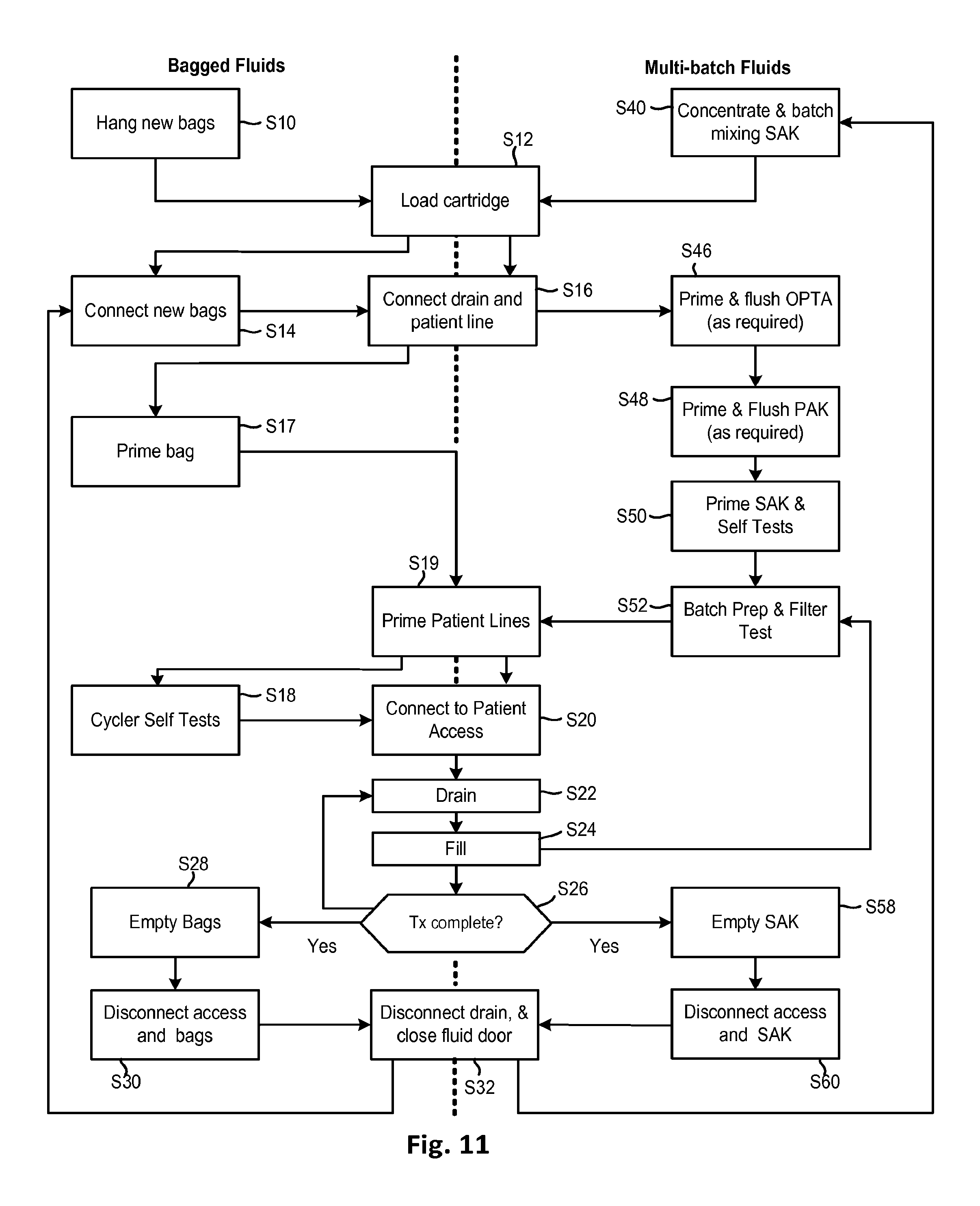
D00015

D00016

D00017

D00018
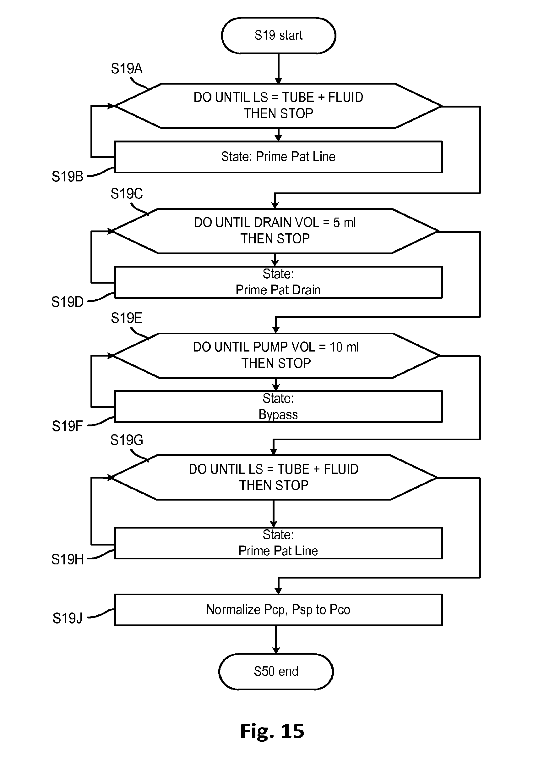
D00019
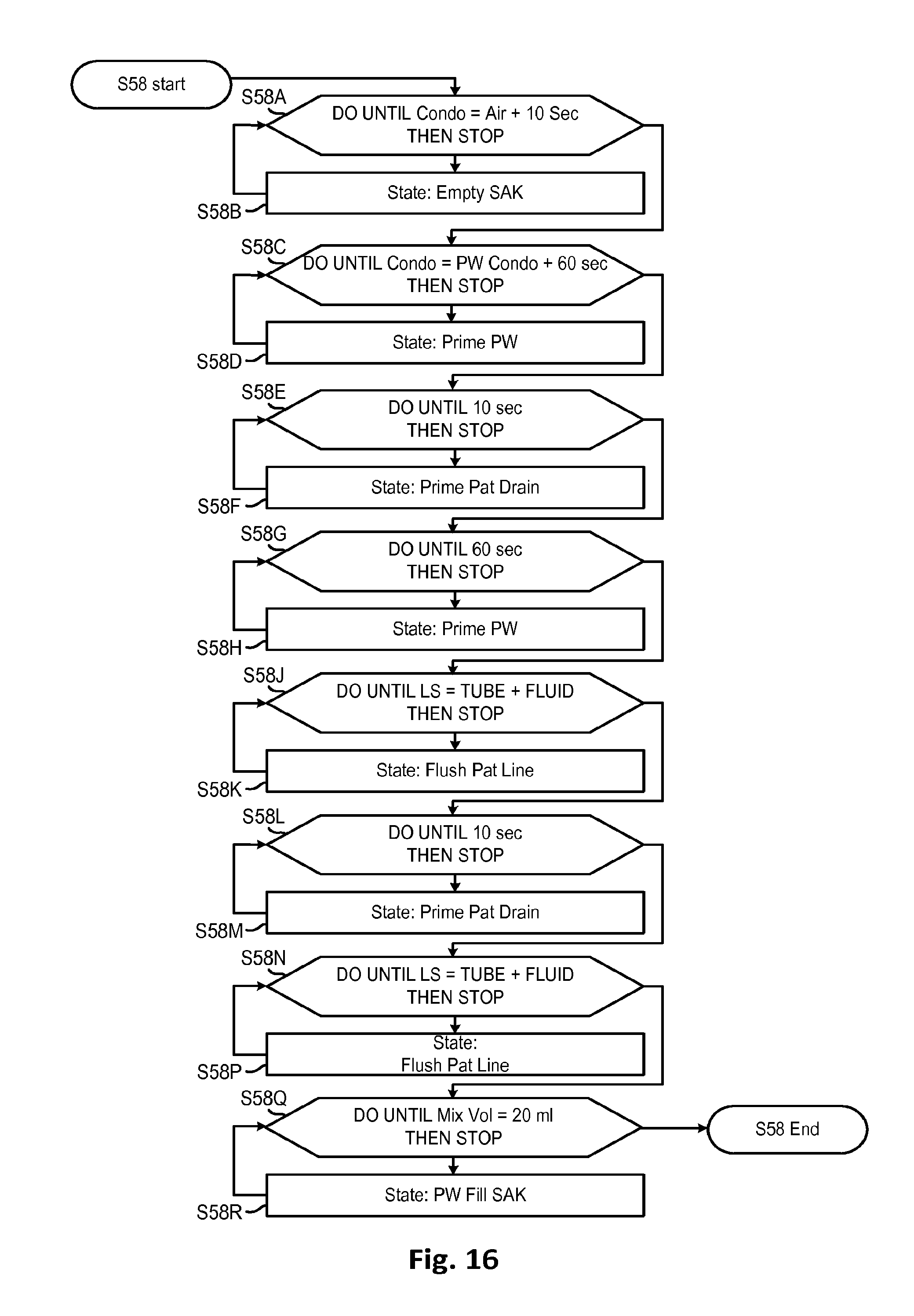
D00020

D00021

D00022

D00023
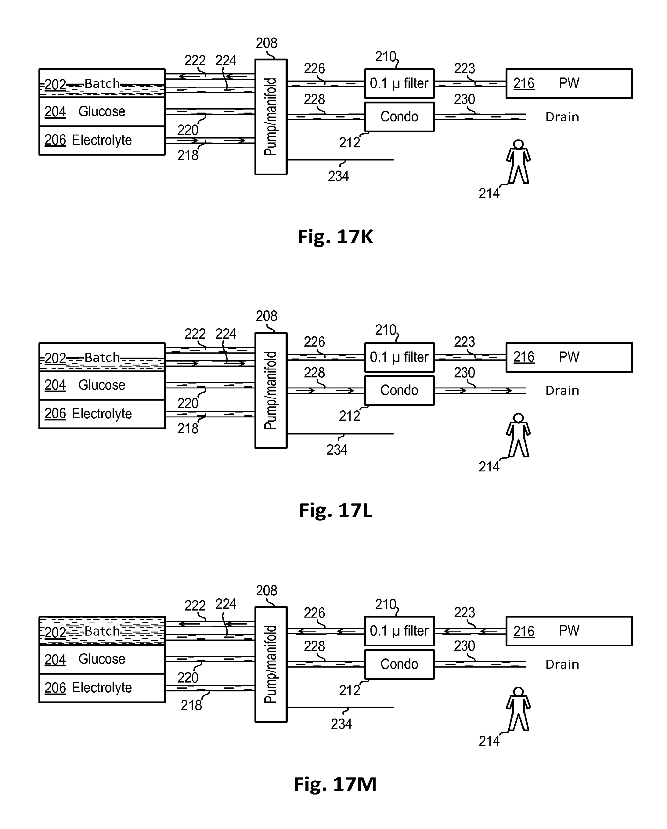
D00024

D00025
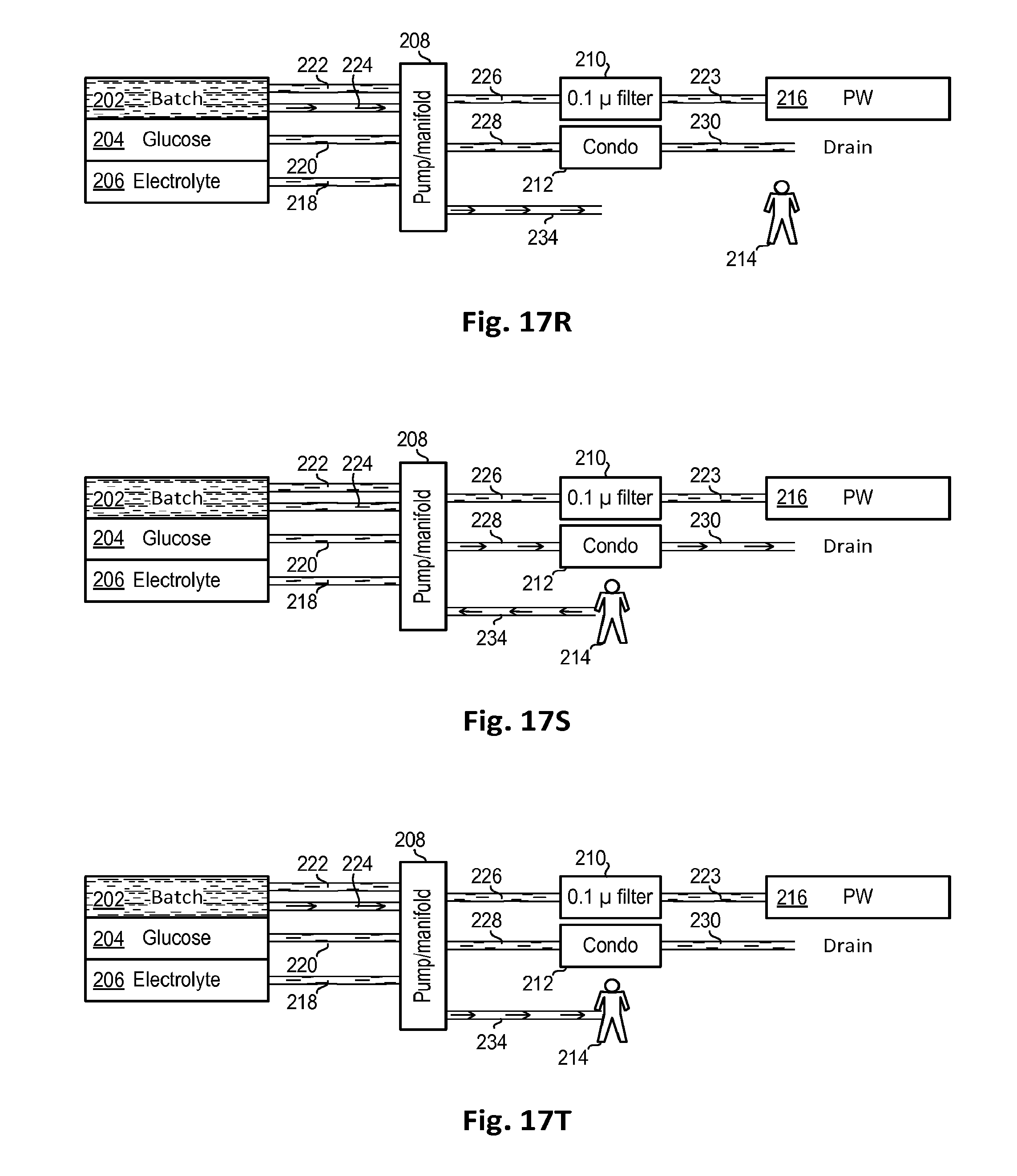
D00026

XML
uspto.report is an independent third-party trademark research tool that is not affiliated, endorsed, or sponsored by the United States Patent and Trademark Office (USPTO) or any other governmental organization. The information provided by uspto.report is based on publicly available data at the time of writing and is intended for informational purposes only.
While we strive to provide accurate and up-to-date information, we do not guarantee the accuracy, completeness, reliability, or suitability of the information displayed on this site. The use of this site is at your own risk. Any reliance you place on such information is therefore strictly at your own risk.
All official trademark data, including owner information, should be verified by visiting the official USPTO website at www.uspto.gov. This site is not intended to replace professional legal advice and should not be used as a substitute for consulting with a legal professional who is knowledgeable about trademark law.