Collapsible anvil plate assemblies for circular surgical stapling devices
Shelton, IV , et al.
U.S. patent number 10,588,612 [Application Number 15/273,358] was granted by the patent office on 2020-03-17 for collapsible anvil plate assemblies for circular surgical stapling devices. This patent grant is currently assigned to Ethicon LLC. The grantee listed for this patent is Ethicon LLC. Invention is credited to Taylor W. Aronhalt, Christopher J. Hess, Kreena R. Modi, Jerome R. Morgan, Christopher J. Schall, Emily A. Schellin, Frederick E. Shelton, IV, William B. Weisenburgh, II, Barry C. Worrell, Joseph E. Young.


View All Diagrams
| United States Patent | 10,588,612 |
| Shelton, IV , et al. | March 17, 2020 |
Collapsible anvil plate assemblies for circular surgical stapling devices
Abstract
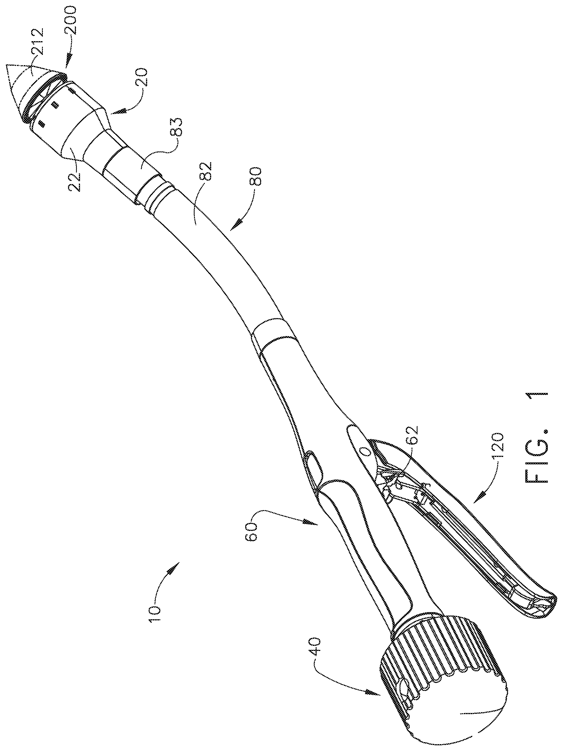
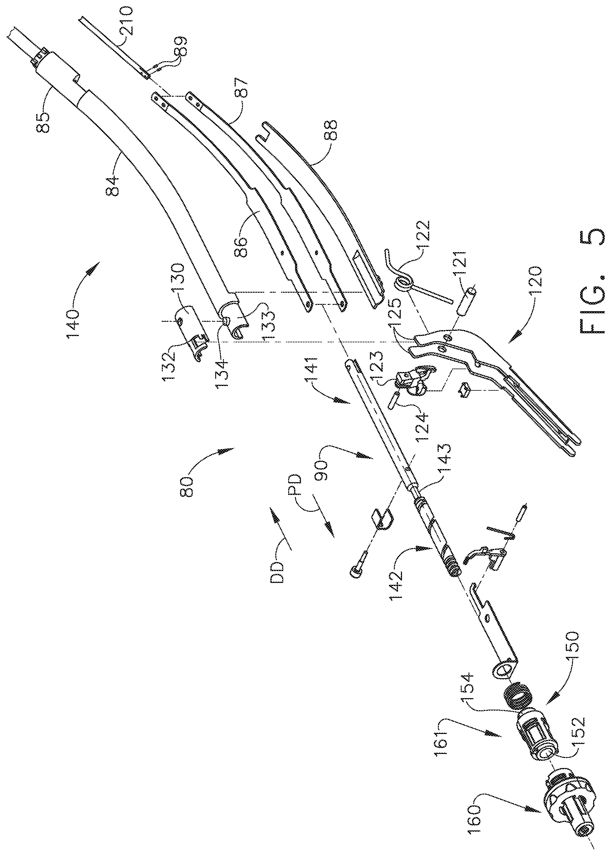
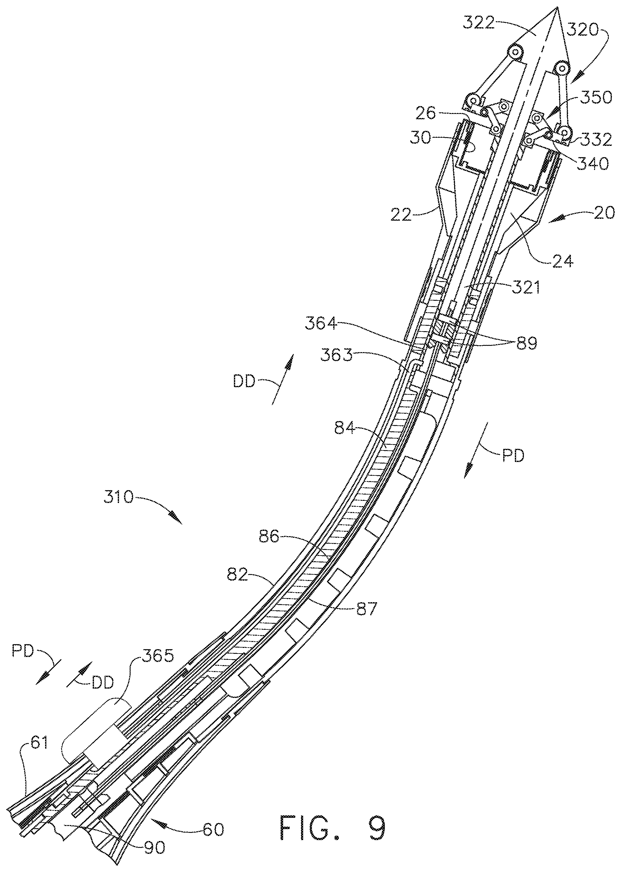
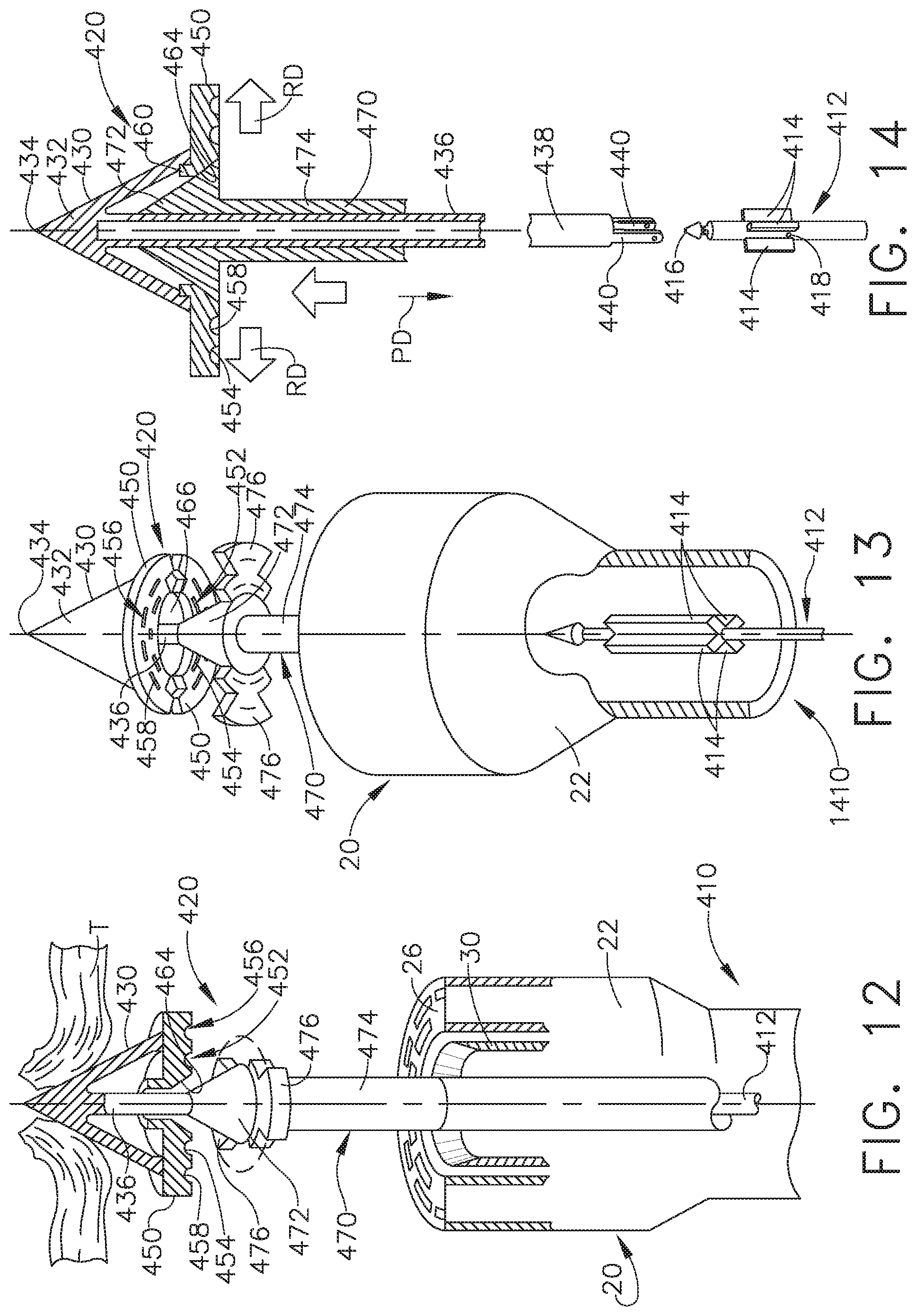
A surgical stapler configured to clamp, staple, and cut tissue is disclosed. The surgical stapler comprises a housing, a shaft, a staple cartridge, an expandable anvil, and a distal head portion. The shaft extends from the housing and comprises three concentric actuators. The three concentric actuators are operable independently of each other. The three concentric actuators are actuatable relative to the housing and are configured to perform three separate and distinct end effector functions. The staple cartridge comprises a unitary cartridge body. The distal head portion is configured to rotate relative to the shaft. One of the separate and distinct end effector functions comprises rotating the distal head portion to expand the anvil.
| Inventors: | Shelton, IV; Frederick E. (Hillsboro, OH), Aronhalt; Taylor W. (Loveland, OH), Modi; Kreena R. (Akron, OH), Schall; Christopher J. (Mason, OH), Young; Joseph E. (Loveland, OH), Worrell; Barry C. (Centerville, OH), Morgan; Jerome R. (Cincinnati, OH), Weisenburgh, II; William B. (Maineville, OH), Hess; Christopher J. (Blue Ash, OH), Schellin; Emily A. (Cincinnati, OH) | ||||||||||
|---|---|---|---|---|---|---|---|---|---|---|---|
| Applicant: |
|
||||||||||
| Assignee: | Ethicon LLC (Guaynabo,
PR) |
||||||||||
| Family ID: | 45926918 | ||||||||||
| Appl. No.: | 15/273,358 | ||||||||||
| Filed: | September 22, 2016 |
Prior Publication Data
| Document Identifier | Publication Date | |
|---|---|---|
| US 20170007229 A1 | Jan 12, 2017 | |
Related U.S. Patent Documents
| Application Number | Filing Date | Patent Number | Issue Date | ||
|---|---|---|---|---|---|
| 14788923 | Jul 1, 2015 | 10130352 | |||
| 13181827 | Jul 28, 2015 | 9089330 | |||
| 61452432 | Mar 14, 2011 | ||||
| Current U.S. Class: | 1/1 |
| Current CPC Class: | A61B 17/0293 (20130101); A61B 17/072 (20130101); A61B 17/068 (20130101); A61B 17/1155 (20130101); A61B 17/00234 (20130101); A61B 17/07207 (20130101); A61B 17/0218 (20130101); A61B 2017/00287 (20130101); F04C 2270/0421 (20130101); A61B 2017/0225 (20130101); A61B 2017/0287 (20130101); A61B 2560/0443 (20130101); A61B 2017/00353 (20130101); A61B 17/3417 (20130101); A61B 2017/00477 (20130101); A61B 2017/07257 (20130101) |
| Current International Class: | A61B 17/072 (20060101); A61B 17/00 (20060101); A61B 17/115 (20060101); A61B 17/02 (20060101); A61B 17/068 (20060101); A61B 17/34 (20060101) |
| Field of Search: | ;227/175.1,176.1,175.2,179.1,180.1 ;606/139,153,219 |
References Cited [Referenced By]
U.S. Patent Documents
| 2224882 | December 1940 | Peck |
| 2742955 | April 1956 | Dominguez |
| 2853074 | September 1958 | Olson |
| 3080564 | March 1963 | Strekopitov et al. |
| 3166072 | January 1965 | Sullivan, Jr. |
| 3266494 | August 1966 | Brownrigg et al. |
| 3359978 | December 1967 | Smith, Jr. |
| 3490675 | January 1970 | Green et al. |
| 3494533 | February 1970 | Green et al. |
| 3551987 | January 1971 | Wilkinson |
| 3643851 | February 1972 | Green et al. |
| 3662939 | May 1972 | Bryan |
| 3717294 | February 1973 | Green |
| 3744495 | July 1973 | Johnson |
| 3746002 | July 1973 | Haller |
| 3819100 | June 1974 | Noiles et al. |
| 3863639 | February 1975 | Kleaveland |
| RE28932 | August 1976 | Noiles et al. |
| 4111206 | September 1978 | Vishnevsky et al. |
| 4190042 | February 1980 | Sinnreich |
| 4198982 | April 1980 | Fortner et al. |
| 4207898 | June 1980 | Becht |
| 4272002 | June 1981 | Moshofsky |
| 4274398 | June 1981 | Scott, Jr. |
| 4289133 | September 1981 | Rothfuss |
| 4304236 | December 1981 | Conta et al. |
| 4331277 | May 1982 | Green |
| 4383634 | May 1983 | Green |
| 4396139 | August 1983 | Hall et al. |
| 4402445 | September 1983 | Green |
| 4408692 | October 1983 | Sigel et al. |
| 4415112 | November 1983 | Green |
| 4417890 | November 1983 | Dennehey et al. |
| 4429695 | February 1984 | Green |
| 4473077 | September 1984 | Noiles et al. |
| 4475679 | October 1984 | Fleury, Jr. |
| 4489875 | December 1984 | Crawford et al. |
| 4500024 | February 1985 | DiGiovanni et al. |
| 4505272 | March 1985 | Utyamyshev et al. |
| 4505273 | March 1985 | Braun et al. |
| 4505414 | March 1985 | Filipi |
| 4506671 | March 1985 | Green |
| 4522327 | June 1985 | Korthoff et al. |
| 4527724 | July 1985 | Chow et al. |
| 4530453 | July 1985 | Green |
| 4566620 | January 1986 | Green et al. |
| 4573468 | March 1986 | Conta et al. |
| 4573622 | March 1986 | Green et al. |
| 4580712 | April 1986 | Green |
| 4585153 | April 1986 | Failla et al. |
| 4605004 | August 1986 | Di Giovanni et al. |
| 4610383 | September 1986 | Rothfuss et al. |
| 4619262 | October 1986 | Taylor |
| 4619391 | October 1986 | Sharkany et al. |
| 4629107 | December 1986 | Fedotov et al. |
| 4632290 | December 1986 | Green et al. |
| 4654028 | March 1987 | Suma |
| 4655222 | April 1987 | Florez et al. |
| 4662555 | May 1987 | Thornton |
| 4664305 | May 1987 | Blake, III et al. |
| 4669647 | June 1987 | Storace |
| 4671445 | June 1987 | Barker et al. |
| 4684051 | August 1987 | Akopov et al. |
| 4700703 | October 1987 | Resnick et al. |
| 4715520 | December 1987 | Roehr, Jr. et al. |
| 4728020 | March 1988 | Green et al. |
| 4744363 | May 1988 | Hasson |
| 4752024 | June 1988 | Green et al. |
| 4754909 | July 1988 | Barker et al. |
| 4767044 | August 1988 | Green |
| 4773420 | September 1988 | Green |
| 4805823 | February 1989 | Rothfuss |
| 4809695 | March 1989 | Gwathmey et al. |
| 4817847 | April 1989 | Redtenbacher et al. |
| 4819853 | April 1989 | Green |
| 4821939 | April 1989 | Green |
| 4844068 | July 1989 | Arata et al. |
| 4848637 | July 1989 | Pruitt |
| 4869414 | September 1989 | Green et al. |
| 4869415 | September 1989 | Fox |
| 4873977 | October 1989 | Avant et al. |
| 4892244 | January 1990 | Fox et al. |
| 4893622 | January 1990 | Green |
| 4903697 | February 1990 | Resnick et al. |
| 4909789 | March 1990 | Taguchi et al. |
| 4921479 | May 1990 | Grayzel |
| 4930674 | June 1990 | Barak |
| 4941623 | July 1990 | Pruitt |
| 4944443 | July 1990 | Oddsen et al. |
| 4973302 | November 1990 | Armour et al. |
| 4984564 | January 1991 | Yuen |
| 5002553 | March 1991 | Shiber |
| 5014899 | May 1991 | Presty et al. |
| 5027834 | July 1991 | Pruitt |
| 5065929 | November 1991 | Schulze et al. |
| 5071430 | December 1991 | de Salis et al. |
| 5074454 | December 1991 | Peters |
| 5080088 | January 1992 | LeVahn |
| 5082005 | January 1992 | Kaldany |
| 5084057 | January 1992 | Green et al. |
| 5104025 | April 1992 | Main et al. |
| 5104397 | April 1992 | Vasconcelos et al. |
| 5108368 | April 1992 | Hammerslag et al. |
| 5116349 | May 1992 | Aranyi |
| 5119983 | June 1992 | Green et al. |
| 5122156 | June 1992 | Granger et al. |
| 5129570 | July 1992 | Schulze et al. |
| 5137198 | August 1992 | Nobis et al. |
| 5139513 | August 1992 | Segato |
| 5141144 | August 1992 | Foslien et al. |
| 5156609 | October 1992 | Nakao et al. |
| 5158567 | October 1992 | Green |
| 5171247 | December 1992 | Hughett et al. |
| 5171249 | December 1992 | Stefanchik et al. |
| 5195505 | March 1993 | Josefsen |
| 5197649 | March 1993 | Bessler et al. |
| 5205459 | April 1993 | Brinkerhoff |
| 5211649 | May 1993 | Kohler et al. |
| 5211655 | May 1993 | Hasson |
| 5221036 | June 1993 | Takase |
| 5222945 | June 1993 | Basnight |
| 5222963 | June 1993 | Brinkerhoff et al. |
| 5222975 | June 1993 | Crainich |
| 5234447 | August 1993 | Kaster et al. |
| 5236440 | August 1993 | Hlavacek |
| 5239981 | August 1993 | Anapliotis |
| 5258009 | November 1993 | Conners |
| 5263937 | November 1993 | Shipp |
| 5271543 | December 1993 | Grant et al. |
| 5275322 | January 1994 | Brinkerhoff et al. |
| 5282806 | February 1994 | Haber et al. |
| 5282829 | February 1994 | Hermes |
| 5285945 | February 1994 | Brinkerhoff et al. |
| 5304204 | April 1994 | Bregen |
| 5309896 | May 1994 | Moll et al. |
| 5309927 | May 1994 | Welch |
| 5312023 | May 1994 | Green et al. |
| 5314445 | May 1994 | Heidmueller nee Degwitz et al. |
| 5330502 | July 1994 | Hassler et al. |
| 5333772 | August 1994 | Rothfuss et al. |
| 5333773 | August 1994 | Main et al. |
| 5336232 | August 1994 | Green et al. |
| 5342385 | August 1994 | Norelli et al. |
| 5342395 | August 1994 | Jarrett et al. |
| 5342396 | August 1994 | Cook |
| 5346115 | September 1994 | Perouse et al. |
| 5350104 | September 1994 | Main et al. |
| 5350400 | September 1994 | Esposito et al. |
| 5354250 | October 1994 | Christensen |
| 5354303 | October 1994 | Spaeth et al. |
| 5358506 | October 1994 | Green et al. |
| 5366479 | November 1994 | McGarry et al. |
| 5374277 | December 1994 | Hassler |
| 5375588 | December 1994 | Yoon |
| 5383880 | January 1995 | Hooven |
| 5383888 | January 1995 | Zvenyatsky et al. |
| 5383895 | January 1995 | Holmes et al. |
| 5391180 | February 1995 | Tovey et al. |
| 5395030 | March 1995 | Kuramoto et al. |
| 5395033 | March 1995 | Byrne et al. |
| 5395384 | March 1995 | Duthoit et al. |
| 5397324 | March 1995 | Carroll et al. |
| 5403312 | April 1995 | Yates et al. |
| 5404870 | April 1995 | Brinkerhoff et al. |
| 5405072 | April 1995 | Zlock et al. |
| 5405073 | April 1995 | Porter |
| 5405344 | April 1995 | Williamson et al. |
| 5405360 | April 1995 | Tovey |
| 5411508 | May 1995 | Bessler et al. |
| 5413267 | May 1995 | Solyntjes et al. |
| 5413272 | May 1995 | Green et al. |
| 5413573 | May 1995 | Koivukangas |
| 5415334 | May 1995 | Williamson et al. |
| 5417361 | May 1995 | Williamson, IV |
| 5419766 | May 1995 | Chang et al. |
| 5425745 | June 1995 | Green et al. |
| 5433721 | July 1995 | Hooven et al. |
| 5441494 | August 1995 | Ortiz |
| 5445644 | August 1995 | Pietrafitta et al. |
| 5449365 | September 1995 | Green et al. |
| 5452836 | September 1995 | Huitema et al. |
| 5452837 | September 1995 | Williamson, IV et al. |
| 5458279 | October 1995 | Plyley |
| 5462215 | October 1995 | Viola et al. |
| 5465894 | November 1995 | Clark et al. |
| 5470006 | November 1995 | Rodak |
| 5470009 | November 1995 | Rodak |
| 5474057 | December 1995 | Makower et al. |
| 5474566 | December 1995 | Alesi et al. |
| 5476479 | December 1995 | Green et al. |
| 5478354 | December 1995 | Tovey et al. |
| 5480089 | January 1996 | Blewett |
| 5480409 | January 1996 | Riza |
| 5482197 | January 1996 | Green et al. |
| 5483952 | January 1996 | Aranyi |
| 5484095 | January 1996 | Green et al. |
| 5484451 | January 1996 | Akopov et al. |
| 5485947 | January 1996 | Olson et al. |
| 5485952 | January 1996 | Fontayne |
| 5487499 | January 1996 | Sorrentino et al. |
| 5487500 | January 1996 | Knodel et al. |
| 5489058 | February 1996 | Plyley et al. |
| 5490819 | February 1996 | Nicholas et al. |
| 5497933 | March 1996 | DeFonzo et al. |
| 5503320 | April 1996 | Webster et al. |
| 5503635 | April 1996 | Sauer et al. |
| 5505363 | April 1996 | Green et al. |
| 5507426 | April 1996 | Young et al. |
| 5509596 | April 1996 | Green et al. |
| 5511564 | April 1996 | Wilk |
| 5514157 | May 1996 | Nicholas et al. |
| 5518163 | May 1996 | Hooven |
| 5518164 | May 1996 | Hooven |
| 5520609 | May 1996 | Moll et al. |
| 5520678 | May 1996 | Heckele et al. |
| 5520700 | May 1996 | Beyar et al. |
| 5527264 | June 1996 | Moll et al. |
| 5529235 | June 1996 | Boiarski et al. |
| 5531856 | July 1996 | Moll et al. |
| 5533661 | July 1996 | Main et al. |
| 5535934 | July 1996 | Boiarski et al. |
| 5535935 | July 1996 | Vidal et al. |
| 5535937 | July 1996 | Boiarski et al. |
| 5540375 | July 1996 | Bolanos et al. |
| 5542594 | August 1996 | McKean et al. |
| 5547117 | August 1996 | Hamblin et al. |
| 5549621 | August 1996 | Bessler et al. |
| 5549637 | August 1996 | Crainich |
| 5551622 | September 1996 | Yoon |
| 5553765 | September 1996 | Knodel et al. |
| 5554169 | September 1996 | Green et al. |
| 5556416 | September 1996 | Clark et al. |
| 5558665 | September 1996 | Kieturakis |
| 5560530 | October 1996 | Bolanos et al. |
| 5560532 | October 1996 | DeFonzo et al. |
| 5562239 | October 1996 | Boiarski et al. |
| 5562241 | October 1996 | Knodel et al. |
| 5562682 | October 1996 | Oberlin et al. |
| 5562690 | October 1996 | Green et al. |
| 5562701 | October 1996 | Huitema et al. |
| 5562702 | October 1996 | Huitema et al. |
| 5564615 | October 1996 | Bishop et al. |
| 5571116 | November 1996 | Bolanos et al. |
| 5571285 | November 1996 | Chow et al. |
| 5575799 | November 1996 | Bolanos et al. |
| 5575803 | November 1996 | Cooper et al. |
| 5575805 | November 1996 | Li |
| 5577654 | November 1996 | Bishop |
| 5579978 | December 1996 | Green et al. |
| 5580067 | December 1996 | Hamblin et al. |
| 5584425 | December 1996 | Savage et al. |
| 5586711 | December 1996 | Plyley et al. |
| 5588579 | December 1996 | Schnut et al. |
| 5588580 | December 1996 | Paul et al. |
| 5588581 | December 1996 | Conlon et al. |
| 5597107 | January 1997 | Knodel et al. |
| 5601224 | February 1997 | Bishop et al. |
| 5603443 | February 1997 | Clark et al. |
| 5605272 | February 1997 | Witt et al. |
| 5605273 | February 1997 | Hamblin et al. |
| 5607094 | March 1997 | Clark et al. |
| 5607095 | March 1997 | Smith et al. |
| 5607450 | March 1997 | Zvenyatsky et al. |
| 5609285 | March 1997 | Grant et al. |
| 5613937 | March 1997 | Garrison et al. |
| 5615820 | April 1997 | Viola |
| 5618303 | April 1997 | Marlow et al. |
| 5618307 | April 1997 | Donlon et al. |
| 5620452 | April 1997 | Yoon |
| 5624452 | April 1997 | Yates |
| 5628446 | May 1997 | Geiste et al. |
| 5628743 | May 1997 | Cimino |
| 5630539 | May 1997 | Plyley et al. |
| 5630540 | May 1997 | Blewett |
| 5632432 | May 1997 | Schulze et al. |
| 5632433 | May 1997 | Grant et al. |
| 5634584 | June 1997 | Okorocha et al. |
| 5636779 | June 1997 | Palmer |
| 5636780 | June 1997 | Green et al. |
| 5639008 | June 1997 | Gallagher et al. |
| 5645209 | July 1997 | Green et al. |
| 5647526 | July 1997 | Green et al. |
| 5649937 | July 1997 | Bito et al. |
| 5651491 | July 1997 | Heaton et al. |
| 5651762 | July 1997 | Bridges |
| 5653373 | August 1997 | Green et al. |
| 5653374 | August 1997 | Young et al. |
| 5653721 | August 1997 | Knodel et al. |
| 5655698 | August 1997 | Yoon |
| 5657921 | August 1997 | Young et al. |
| 5662258 | September 1997 | Knodel et al. |
| 5662260 | September 1997 | Yoon |
| 5667517 | September 1997 | Hooven |
| 5667526 | September 1997 | Levin |
| 5667527 | September 1997 | Cook |
| 5669544 | September 1997 | Schulze et al. |
| 5669918 | September 1997 | Balazs et al. |
| 5673840 | October 1997 | Schulze et al. |
| 5673841 | October 1997 | Schulze et al. |
| 5680981 | October 1997 | Mililli et al. |
| 5680982 | October 1997 | Schulze et al. |
| 5680983 | October 1997 | Plyley et al. |
| 5681341 | October 1997 | Lunsford et al. |
| 5683349 | November 1997 | Makower et al. |
| 5685474 | November 1997 | Seeber |
| 5685826 | November 1997 | Bonutti |
| 5688270 | November 1997 | Yates et al. |
| 5690269 | November 1997 | Bolanos et al. |
| 5692668 | December 1997 | Schulze et al. |
| 5693042 | December 1997 | Boiarski et al. |
| 5695504 | December 1997 | Gifford, III |
| 5695524 | December 1997 | Kelley et al. |
| 5697543 | December 1997 | Burdorff |
| 5697943 | December 1997 | Sauer et al. |
| 5700270 | December 1997 | Peyser et al. |
| 5702408 | December 1997 | Wales et al. |
| 5702409 | December 1997 | Rayburn et al. |
| 5704534 | January 1998 | Huitema et al. |
| 5706997 | January 1998 | Green et al. |
| 5706998 | January 1998 | Plyley et al. |
| 5707392 | January 1998 | Kortenbach |
| 5709334 | January 1998 | Sorrentino et al. |
| 5709680 | January 1998 | Yates et al. |
| 5709706 | January 1998 | Kienzle et al. |
| 5711472 | January 1998 | Bryan |
| 5713505 | February 1998 | Huitema |
| 5715987 | February 1998 | Kelley et al. |
| 5716366 | February 1998 | Yates |
| 5718359 | February 1998 | Palmer et al. |
| 5718360 | February 1998 | Green et al. |
| 5725536 | March 1998 | Oberlin et al. |
| 5725554 | March 1998 | Simon et al. |
| 5728121 | March 1998 | Bimbo et al. |
| 5730758 | March 1998 | Allgeyer |
| 5732871 | March 1998 | Clark et al. |
| 5732872 | March 1998 | Bolduc et al. |
| 5735874 | April 1998 | Measamer et al. |
| 5738629 | April 1998 | Moll et al. |
| 5741271 | April 1998 | Nakao et al. |
| 5743456 | April 1998 | Jones et al. |
| 5749889 | May 1998 | Bacich et al. |
| 5749893 | May 1998 | Vidal et al. |
| 5752644 | May 1998 | Bolanos et al. |
| 5752965 | May 1998 | Francis et al. |
| 5752970 | May 1998 | Yoon |
| 5758814 | June 1998 | Gallagher et al. |
| 5762255 | June 1998 | Chrisman et al. |
| 5762256 | June 1998 | Mastri et al. |
| 5766188 | June 1998 | Igaki |
| 5766205 | June 1998 | Zvenyatsky et al. |
| 5769892 | June 1998 | Kingwell |
| 5779130 | July 1998 | Alesi et al. |
| 5779131 | July 1998 | Knodel et al. |
| 5779132 | July 1998 | Knodel et al. |
| 5782396 | July 1998 | Mastri et al. |
| 5782397 | July 1998 | Koukline |
| 5782859 | July 1998 | Nicholas et al. |
| 5785232 | July 1998 | Vidal et al. |
| 5785647 | July 1998 | Tompkins et al. |
| 5787897 | August 1998 | Kieturakis |
| 5792135 | August 1998 | Madhani et al. |
| 5794834 | August 1998 | Hamblin et al. |
| 5797536 | August 1998 | Smith et al. |
| 5797537 | August 1998 | Oberlin et al. |
| 5797538 | August 1998 | Heaton et al. |
| 5797959 | August 1998 | Castro et al. |
| 5799857 | September 1998 | Robertson et al. |
| 5807376 | September 1998 | Viola et al. |
| 5807378 | September 1998 | Jensen et al. |
| 5810721 | September 1998 | Mueller et al. |
| 5810811 | September 1998 | Yates et al. |
| 5810855 | September 1998 | Rayburn et al. |
| 5814055 | September 1998 | Knodel et al. |
| 5814057 | September 1998 | Oi et al. |
| 5817084 | October 1998 | Jensen |
| 5817093 | October 1998 | Williamson, IV et al. |
| 5820009 | October 1998 | Melling et al. |
| 5826776 | October 1998 | Schulze et al. |
| 5827298 | October 1998 | Hart et al. |
| 5829662 | November 1998 | Allen et al. |
| 5833695 | November 1998 | Yoon |
| 5836503 | November 1998 | Ehrenfels et al. |
| 5839369 | November 1998 | Chatterjee et al. |
| 5839639 | November 1998 | Sauer et al. |
| 5843096 | December 1998 | Igaki et al. |
| 5855311 | January 1999 | Hamblin et al. |
| 5855583 | January 1999 | Wang et al. |
| 5860581 | January 1999 | Robertson |
| 5865361 | February 1999 | Milliman et al. |
| 5868760 | February 1999 | McGuckin, Jr. |
| 5871135 | February 1999 | Williamson, IV et al. |
| 5876401 | March 1999 | Schulze et al. |
| 5878937 | March 1999 | Green et al. |
| 5893506 | April 1999 | Powell |
| 5894979 | April 1999 | Powell |
| 5897562 | April 1999 | Bolanos et al. |
| 5901895 | May 1999 | Heaton et al. |
| 5902312 | May 1999 | Frater et al. |
| 5906577 | May 1999 | Beane et al. |
| 5906625 | May 1999 | Bito et al. |
| 5908427 | June 1999 | McKean et al. |
| 5911353 | June 1999 | Bolanos et al. |
| 5915616 | June 1999 | Viola et al. |
| 5918791 | July 1999 | Sorrentino et al. |
| 5919198 | July 1999 | Graves, Jr. et al. |
| 5931853 | August 1999 | McEwen et al. |
| 5937951 | August 1999 | Izuchukwu et al. |
| 5938667 | August 1999 | Peyser et al. |
| 5941442 | August 1999 | Geiste et al. |
| 5947984 | September 1999 | Whipple |
| 5951576 | September 1999 | Wakabayashi |
| 5954259 | September 1999 | Viola et al. |
| 5964774 | October 1999 | McKean et al. |
| 5997528 | December 1999 | Bisch et al. |
| 5997552 | December 1999 | Person et al. |
| 6003517 | December 1999 | Sheffield et al. |
| 6010054 | January 2000 | Johnson et al. |
| 6017356 | January 2000 | Frederick et al. |
| 6024741 | February 2000 | Williamson, IV et al. |
| 6024748 | February 2000 | Manzo et al. |
| 6032849 | March 2000 | Mastri et al. |
| 6045560 | April 2000 | McKean et al. |
| 6050472 | April 2000 | Shibata |
| 6053390 | April 2000 | Green et al. |
| RE36720 | May 2000 | Green et al. |
| 6056735 | May 2000 | Okada et al. |
| 6063025 | May 2000 | Bridges et al. |
| 6063097 | May 2000 | Oi et al. |
| 6066132 | May 2000 | Chen et al. |
| 6074401 | June 2000 | Gardiner et al. |
| 6079606 | June 2000 | Milliman et al. |
| 6083234 | July 2000 | Nicholas et al. |
| 6083241 | July 2000 | Longo et al. |
| 6083242 | July 2000 | Cook |
| 6086600 | July 2000 | Kortenbach |
| 6099551 | August 2000 | Gabbay |
| 6102271 | August 2000 | Longo et al. |
| 6109500 | August 2000 | Alli et al. |
| 6117148 | September 2000 | Ravo et al. |
| 6117158 | September 2000 | Measamer et al. |
| 6119913 | September 2000 | Adams et al. |
| H001904 | October 2000 | Yates et al. |
| 6126058 | October 2000 | Adams et al. |
| 6131790 | October 2000 | Piraka |
| 6142933 | November 2000 | Longo et al. |
| 6155473 | December 2000 | Tompkins et al. |
| 6159146 | December 2000 | El Gazayerli |
| 6159200 | December 2000 | Verdura et al. |
| 6162208 | December 2000 | Hipps |
| 6165188 | December 2000 | Saadat et al. |
| 6171330 | January 2001 | Benchetrit |
| 6174318 | January 2001 | Bates et al. |
| 6179195 | January 2001 | Adams et al. |
| 6193129 | February 2001 | Bittner et al. |
| 6202914 | March 2001 | Geiste et al. |
| 6214020 | April 2001 | Mulhauser et al. |
| 6214028 | April 2001 | Yoon et al. |
| 6216698 | April 2001 | Regula |
| 6221007 | April 2001 | Green |
| 6231565 | May 2001 | Tovey et al. |
| 6234178 | May 2001 | Goble et al. |
| 6241139 | June 2001 | Milliman et al. |
| 6241140 | June 2001 | Adams et al. |
| 6241723 | June 2001 | Heim et al. |
| 6248117 | June 2001 | Blatter |
| 6250532 | June 2001 | Green et al. |
| 6254534 | July 2001 | Butler et al. |
| 6258107 | July 2001 | Balazs et al. |
| 6264086 | July 2001 | McGuckin, Jr. |
| 6264087 | July 2001 | Whitman |
| 6267772 | July 2001 | Mulhauser et al. |
| 6273897 | August 2001 | Dalessandro et al. |
| 6293927 | September 2001 | McGuckin, Jr. |
| 6302311 | October 2001 | Adams et al. |
| 6309403 | October 2001 | Minor et al. |
| 6315184 | November 2001 | Whitman |
| 6325810 | December 2001 | Hamilton et al. |
| 6330965 | December 2001 | Milliman et al. |
| 6331181 | December 2001 | Tierney et al. |
| 6338737 | January 2002 | Toledano |
| 6343731 | February 2002 | Adams et al. |
| 6346077 | February 2002 | Taylor |
| 6352503 | March 2002 | Matsui et al. |
| 6364888 | April 2002 | Niemeyer et al. |
| 6387113 | May 2002 | Hawkins et al. |
| 6391038 | May 2002 | Vargas et al. |
| 6398797 | June 2002 | Bombard et al. |
| 6402766 | June 2002 | Bowman et al. |
| 6402780 | June 2002 | Williamson, IV et al. |
| RE37814 | August 2002 | Allgeyer |
| 6436107 | August 2002 | Wang et al. |
| 6436110 | August 2002 | Bowman et al. |
| 6436122 | August 2002 | Frank et al. |
| 6439446 | August 2002 | Perry et al. |
| 6440146 | August 2002 | Nicholas et al. |
| 6443973 | September 2002 | Whitman |
| 6447523 | September 2002 | Middleman et al. |
| 6450391 | September 2002 | Kayan et al. |
| 6458077 | October 2002 | Boebel et al. |
| 6478210 | November 2002 | Adams et al. |
| 6488196 | December 2002 | Fenton, Jr. |
| 6488197 | December 2002 | Whitman |
| 6491201 | December 2002 | Whitman |
| 6491701 | December 2002 | Tierney et al. |
| 6494885 | December 2002 | Dhindsa |
| 6503257 | January 2003 | Grant et al. |
| 6503259 | January 2003 | Huxel |
| 6505768 | January 2003 | Whitman |
| 6510854 | January 2003 | Goble |
| 6517528 | February 2003 | Pantages et al. |
| 6517565 | February 2003 | Whitman et al. |
| 6517566 | February 2003 | Hovland et al. |
| 6533157 | March 2003 | Whitman |
| 6540737 | April 2003 | Bacher et al. |
| 6543456 | April 2003 | Freeman |
| 6551333 | April 2003 | Kuhns et al. |
| 6569171 | May 2003 | DeGuillebon et al. |
| 6578751 | June 2003 | Hartwick |
| 6582364 | June 2003 | Butler et al. |
| 6585144 | July 2003 | Adams et al. |
| 6588643 | July 2003 | Bolduc et al. |
| 6592597 | July 2003 | Grant et al. |
| 6601749 | August 2003 | Sullivan et al. |
| 6605078 | August 2003 | Adams |
| 6616686 | September 2003 | Coleman et al. |
| 6619529 | September 2003 | Green et al. |
| 6629630 | October 2003 | Adams |
| 6629988 | October 2003 | Weadock |
| 6638285 | October 2003 | Gabbay |
| 6638297 | October 2003 | Huitema |
| 6644532 | November 2003 | Green et al. |
| 6645201 | November 2003 | Utley et al. |
| 6648901 | November 2003 | Fleischman et al. |
| 6656193 | December 2003 | Grant et al. |
| 6666854 | December 2003 | Lange |
| 6669073 | December 2003 | Milliman et al. |
| 6681978 | January 2004 | Geiste et al. |
| 6681979 | January 2004 | Whitman |
| 6682528 | January 2004 | Frazier et al. |
| 6692507 | February 2004 | Pugsley et al. |
| 6695198 | February 2004 | Adams et al. |
| 6695199 | February 2004 | Whitman |
| 6698643 | March 2004 | Whitman |
| 6699235 | March 2004 | Wallace et al. |
| 6716232 | April 2004 | Vidal et al. |
| 6716233 | April 2004 | Whitman |
| 6722552 | April 2004 | Fenton, Jr. |
| 6723087 | April 2004 | O'Neill et al. |
| 6726697 | April 2004 | Nicholas et al. |
| 6736825 | May 2004 | Blatter et al. |
| 6749600 | June 2004 | Levy |
| 6752816 | June 2004 | Culp et al. |
| 6755338 | June 2004 | Hahnen et al. |
| 6769590 | August 2004 | Vresh |
| 6769594 | August 2004 | Orban, III |
| 6773438 | August 2004 | Knodel et al. |
| 6780151 | August 2004 | Grabover et al. |
| 6786382 | September 2004 | Hoffman |
| 6786896 | September 2004 | Madhani et al. |
| 6793652 | September 2004 | Whitman et al. |
| 6805273 | October 2004 | Bilotti et al. |
| 6817508 | November 2004 | Racenet et al. |
| 6817509 | November 2004 | Geiste et al. |
| 6820791 | November 2004 | Adams |
| 6821284 | November 2004 | Sturtz et al. |
| 6827246 | December 2004 | Sullivan et al. |
| 6827712 | December 2004 | Tovey et al. |
| 6830174 | December 2004 | Hillstead et al. |
| 6835199 | December 2004 | McGuckin, Jr. et al. |
| 6840423 | January 2005 | Adams et al. |
| 6843403 | January 2005 | Whitman |
| 6846307 | January 2005 | Whitman et al. |
| 6846308 | January 2005 | Whitman et al. |
| 6846309 | January 2005 | Whitman et al. |
| 6849071 | February 2005 | Whitman et al. |
| RE38708 | March 2005 | Bolanos et al. |
| 6866178 | March 2005 | Adams et al. |
| 6866671 | March 2005 | Tierney et al. |
| 6872214 | March 2005 | Sonnenschein et al. |
| 6874669 | April 2005 | Adams et al. |
| 6877647 | April 2005 | Green et al. |
| 6905057 | June 2005 | Swayze et al. |
| 6913608 | July 2005 | Liddicoat et al. |
| 6913613 | July 2005 | Schwarz et al. |
| 6936042 | August 2005 | Wallace et al. |
| 6939358 | September 2005 | Palacios et al. |
| 6945444 | September 2005 | Gresham et al. |
| 6953138 | October 2005 | Dworak et al. |
| 6953139 | October 2005 | Milliman et al. |
| 6959851 | November 2005 | Heinrich |
| 6959852 | November 2005 | Shelton, IV et al. |
| 6960220 | November 2005 | Marino et al. |
| 6964363 | November 2005 | Wales et al. |
| 6971988 | December 2005 | Orban, III |
| 6978921 | December 2005 | Shelton, IV et al. |
| 6978922 | December 2005 | Bilotti et al. |
| 6981628 | January 2006 | Wales |
| 6981978 | January 2006 | Gannoe |
| 6986451 | January 2006 | Mastri et al. |
| 6988649 | January 2006 | Shelton, IV et al. |
| 6988650 | January 2006 | Schwemberger et al. |
| 6997931 | February 2006 | Sauer et al. |
| 7000818 | February 2006 | Shelton, IV et al. |
| 7000819 | February 2006 | Swayze et al. |
| 7001408 | February 2006 | Knodel et al. |
| 7008435 | March 2006 | Cummins |
| 7032798 | April 2006 | Whitman et al. |
| 7032799 | April 2006 | Viola et al. |
| 7037314 | May 2006 | Armstrong |
| 7044352 | May 2006 | Shelton, IV et al. |
| 7044353 | May 2006 | Mastri et al. |
| 7052454 | May 2006 | Taylor |
| 7055731 | June 2006 | Shelton, IV et al. |
| 7056330 | June 2006 | Gayton |
| 7059331 | June 2006 | Adams et al. |
| 7059508 | June 2006 | Shelton, IV et al. |
| 7063712 | June 2006 | Vargas et al. |
| 7066944 | June 2006 | Laufer et al. |
| 7070083 | July 2006 | Jankowski |
| 7077856 | July 2006 | Whitman |
| 7080769 | July 2006 | Vresh et al. |
| 7083075 | August 2006 | Swayze et al. |
| 7083626 | August 2006 | Hart et al. |
| 7087071 | August 2006 | Nicholas et al. |
| 7090673 | August 2006 | Dycus et al. |
| 7090683 | August 2006 | Brock et al. |
| 7090684 | August 2006 | McGuckin, Jr. et al. |
| 7094247 | August 2006 | Monassevitch et al. |
| 7097089 | August 2006 | Marczyk |
| 7108701 | September 2006 | Evens et al. |
| 7108709 | September 2006 | Cummins |
| 7111769 | September 2006 | Wales et al. |
| 7114642 | October 2006 | Whitman |
| 7118582 | October 2006 | Wang et al. |
| 7121446 | October 2006 | Arad et al. |
| 7122028 | October 2006 | Looper et al. |
| 7128253 | October 2006 | Mastri et al. |
| 7128254 | October 2006 | Shelton, IV et al. |
| 7128748 | October 2006 | Mooradian et al. |
| 7131445 | November 2006 | Amoah |
| 7134587 | November 2006 | Schwemberger et al. |
| 7140527 | November 2006 | Ehrenfels et al. |
| 7140528 | November 2006 | Shelton, IV |
| 7143923 | December 2006 | Shelton, IV et al. |
| 7143924 | December 2006 | Scirica et al. |
| 7143925 | December 2006 | Shelton, IV et al. |
| 7143926 | December 2006 | Shelton, IV et al. |
| 7147138 | December 2006 | Shelton, IV |
| 7147139 | December 2006 | Schwemberger et al. |
| 7147650 | December 2006 | Lee |
| 7156863 | January 2007 | Sonnenschein et al. |
| 7159750 | January 2007 | Racenet et al. |
| 7160299 | January 2007 | Baily |
| 7168604 | January 2007 | Milliman et al. |
| 7172104 | February 2007 | Scirica et al. |
| 7179267 | February 2007 | Nolan et al. |
| 7182239 | February 2007 | Myers |
| 7188758 | March 2007 | Viola et al. |
| 7207471 | April 2007 | Heinrich et al. |
| 7207472 | April 2007 | Wukusick et al. |
| 7208005 | April 2007 | Frecker et al. |
| 7210609 | May 2007 | Leiboff et al. |
| 7213736 | May 2007 | Wales et al. |
| 7220272 | May 2007 | Weadock |
| 7225963 | June 2007 | Scirica |
| 7225964 | June 2007 | Mastri et al. |
| 7229408 | June 2007 | Douglas et al. |
| 7234624 | June 2007 | Gresham et al. |
| 7235089 | June 2007 | McGuckin, Jr. |
| 7237708 | July 2007 | Guy et al. |
| 7238195 | July 2007 | Viola |
| 7241288 | July 2007 | Braun |
| 7246734 | July 2007 | Shelton, IV |
| 7252660 | August 2007 | Kunz |
| 7258262 | August 2007 | Mastri et al. |
| 7267679 | September 2007 | McGuckin, Jr. et al. |
| 7278562 | October 2007 | Mastri et al. |
| 7278563 | October 2007 | Green |
| 7296722 | November 2007 | Ivanko |
| 7296724 | November 2007 | Green et al. |
| 7297149 | November 2007 | Vitali et al. |
| 7300450 | November 2007 | Vleugels et al. |
| 7303106 | December 2007 | Milliman et al. |
| 7303107 | December 2007 | Milliman et al. |
| 7303108 | December 2007 | Shelton, IV |
| 7308998 | December 2007 | Mastri et al. |
| 7328828 | February 2008 | Ortiz et al. |
| 7328829 | February 2008 | Arad et al. |
| 7334717 | February 2008 | Rethy et al. |
| 7334718 | February 2008 | McAlister et al. |
| 7338505 | March 2008 | Belson |
| 7338513 | March 2008 | Lee et al. |
| 7343920 | March 2008 | Toby et al. |
| RE40237 | April 2008 | Bilotti et al. |
| 7354447 | April 2008 | Shelton, IV et al. |
| 7357287 | April 2008 | Shelton, IV et al. |
| 7364060 | April 2008 | Milliman |
| 7364061 | April 2008 | Swayze et al. |
| 7377928 | May 2008 | Zubik et al. |
| 7380695 | June 2008 | Doll et al. |
| 7380696 | June 2008 | Shelton, IV et al. |
| 7396356 | July 2008 | Mollenauer |
| 7398907 | July 2008 | Racenet et al. |
| 7398908 | July 2008 | Holsten et al. |
| 7401721 | July 2008 | Holsten et al. |
| 7404508 | July 2008 | Smith et al. |
| 7404509 | July 2008 | Ortiz et al. |
| 7404822 | July 2008 | Viart et al. |
| 7407074 | August 2008 | Ortiz et al. |
| 7407075 | August 2008 | Holsten et al. |
| 7407076 | August 2008 | Racenet et al. |
| 7407077 | August 2008 | Ortiz et al. |
| 7407078 | August 2008 | Shelton, IV et al. |
| 7410086 | August 2008 | Ortiz et al. |
| 7416101 | August 2008 | Shelton, IV et al. |
| RE40514 | September 2008 | Mastri et al. |
| 7419080 | September 2008 | Smith et al. |
| 7419081 | September 2008 | Ehrenfels et al. |
| 7422136 | September 2008 | Marczyk |
| 7422139 | September 2008 | Shelton, IV et al. |
| 7424965 | September 2008 | Racenet et al. |
| 7431188 | October 2008 | Marczyk |
| 7431189 | October 2008 | Shelton, IV et al. |
| 7431730 | October 2008 | Viola |
| 7434715 | October 2008 | Shelton, IV et al. |
| 7434717 | October 2008 | Shelton, IV et al. |
| 7438209 | October 2008 | Hess et al. |
| 7438718 | October 2008 | Milliman et al. |
| 7441684 | October 2008 | Shelton, IV et al. |
| 7441685 | October 2008 | Boudreaux |
| 7442201 | October 2008 | Pugsley et al. |
| 7448525 | November 2008 | Shelton, IV et al. |
| 7455208 | November 2008 | Wales et al. |
| 7455676 | November 2008 | Holsten et al. |
| 7455682 | November 2008 | Viola |
| 7461767 | December 2008 | Viola et al. |
| 7464846 | December 2008 | Shelton, IV et al. |
| 7464847 | December 2008 | Viola et al. |
| 7464849 | December 2008 | Shelton, IV et al. |
| 7467740 | December 2008 | Shelton, IV et al. |
| 7472814 | January 2009 | Mastri et al. |
| 7472815 | January 2009 | Shelton, IV et al. |
| 7472816 | January 2009 | Holsten et al. |
| 7473221 | January 2009 | Ewers et al. |
| 7481347 | January 2009 | Roy |
| 7481348 | January 2009 | Marczyk |
| 7481349 | January 2009 | Holsten et al. |
| 7481824 | January 2009 | Boudreaux et al. |
| 7487899 | February 2009 | Shelton, IV et al. |
| 7490749 | February 2009 | Schall et al. |
| 7491232 | February 2009 | Bolduc et al. |
| 7494039 | February 2009 | Racenet et al. |
| 7494499 | February 2009 | Nagase et al. |
| 7500979 | March 2009 | Hueil et al. |
| 7503474 | March 2009 | Hillstead et al. |
| 7506790 | March 2009 | Shelton, IV |
| 7506791 | March 2009 | Omaits et al. |
| 7510107 | March 2009 | Timm et al. |
| 7513408 | April 2009 | Shelton, IV et al. |
| 7517356 | April 2009 | Heinrich |
| 7524320 | April 2009 | Tierney et al. |
| 7527632 | May 2009 | Houghton et al. |
| 7530984 | May 2009 | Sonnenschein et al. |
| 7546939 | June 2009 | Adams et al. |
| 7546940 | June 2009 | Milliman et al. |
| 7547312 | June 2009 | Bauman et al. |
| 7549563 | June 2009 | Mather et al. |
| 7549564 | June 2009 | Boudreaux |
| 7549998 | June 2009 | Braun |
| 7556185 | July 2009 | Viola |
| 7556186 | July 2009 | Milliman |
| 7556647 | July 2009 | Drews et al. |
| 7559449 | July 2009 | Viola |
| 7559450 | July 2009 | Wales et al. |
| 7559452 | July 2009 | Wales et al. |
| 7565993 | July 2009 | Milliman et al. |
| 7568603 | August 2009 | Shelton, IV et al. |
| 7568604 | August 2009 | Ehrenfels et al. |
| 7575144 | August 2009 | Ortiz et al. |
| 7588174 | September 2009 | Holsten et al. |
| 7588175 | September 2009 | Timm et al. |
| 7588176 | September 2009 | Timm et al. |
| 7588177 | September 2009 | Racenet |
| 7597229 | October 2009 | Boudreaux et al. |
| 7597230 | October 2009 | Racenet et al. |
| 7600663 | October 2009 | Green |
| 7604150 | October 2009 | Boudreaux |
| 7604151 | October 2009 | Hess et al. |
| 7607557 | October 2009 | Shelton, IV et al. |
| 7611038 | November 2009 | Racenet et al. |
| 7624902 | December 2009 | Marczyk et al. |
| 7624903 | December 2009 | Green et al. |
| 7631793 | December 2009 | Rethy et al. |
| 7631794 | December 2009 | Rethy et al. |
| 7635074 | December 2009 | Olson et al. |
| 7637409 | December 2009 | Marczyk |
| 7641091 | January 2010 | Olson et al. |
| 7641092 | January 2010 | Kruszynski et al. |
| 7641095 | January 2010 | Viola |
| 7644848 | January 2010 | Swayze et al. |
| 7648519 | January 2010 | Lee et al. |
| 7651017 | January 2010 | Ortiz et al. |
| 7654431 | February 2010 | Hueil et al. |
| 7658311 | February 2010 | Boudreaux |
| 7658312 | February 2010 | Vidal et al. |
| 7662161 | February 2010 | Briganti et al. |
| 7665646 | February 2010 | Prommersberger |
| 7665647 | February 2010 | Shelton, IV et al. |
| 7669746 | March 2010 | Shelton, IV |
| 7669747 | March 2010 | Weisenburgh, II et al. |
| 7670334 | March 2010 | Hueil et al. |
| 7673780 | March 2010 | Shelton, IV et al. |
| 7673781 | March 2010 | Swayze et al. |
| 7673782 | March 2010 | Hess et al. |
| 7673783 | March 2010 | Morgan et al. |
| 7674255 | March 2010 | Braun |
| 7682686 | March 2010 | Curro et al. |
| 7686201 | March 2010 | Csiky |
| 7686826 | March 2010 | Lee et al. |
| 7691098 | April 2010 | Wallace et al. |
| 7694864 | April 2010 | Okada et al. |
| 7694865 | April 2010 | Scirica |
| 7699204 | April 2010 | Viola |
| 7699844 | April 2010 | Utley et al. |
| 7699859 | April 2010 | Bombard et al. |
| 7703653 | April 2010 | Shah et al. |
| 7708180 | May 2010 | Murray et al. |
| 7708181 | May 2010 | Cole |
| 7708758 | May 2010 | Lee et al. |
| 7717312 | May 2010 | Beetel |
| 7717313 | May 2010 | Criscuolo et al. |
| 7717873 | May 2010 | Swick |
| 7721930 | May 2010 | McKenna et al. |
| 7721931 | May 2010 | Shelton, IV et al. |
| 7721933 | May 2010 | Ehrenfels et al. |
| 7721934 | May 2010 | Shelton, IV et al. |
| 7721936 | May 2010 | Shalton, IV et al. |
| 7726537 | June 2010 | Olson et al. |
| 7726538 | June 2010 | Holsten et al. |
| 7731072 | June 2010 | Timm et al. |
| 7735703 | June 2010 | Morgan et al. |
| 7736306 | June 2010 | Brustad et al. |
| 7738971 | June 2010 | Swayze et al. |
| 7740159 | June 2010 | Shelton, IV et al. |
| 7743960 | June 2010 | Whitman et al. |
| 7744624 | June 2010 | Bettuchi |
| 7744627 | June 2010 | Orban, III et al. |
| 7744628 | June 2010 | Viola |
| 7753245 | July 2010 | Boudreaux et al. |
| 7753904 | July 2010 | Shelton, IV et al. |
| 7758612 | July 2010 | Shipp |
| 7766207 | August 2010 | Mather et al. |
| 7766209 | August 2010 | Baxter, III et al. |
| 7766210 | August 2010 | Shelton, IV et al. |
| 7766821 | August 2010 | Brunnen et al. |
| 7770773 | August 2010 | Whitman et al. |
| 7770774 | August 2010 | Mastri et al. |
| 7770775 | August 2010 | Shelton, IV et al. |
| 7770776 | August 2010 | Chen et al. |
| 7776060 | August 2010 | Mooradian et al. |
| 7780054 | August 2010 | Wales |
| 7780055 | August 2010 | Scirica et al. |
| 7780685 | August 2010 | Hunt et al. |
| 7784662 | August 2010 | Wales et al. |
| 7784663 | August 2010 | Shelton, IV |
| 7789889 | September 2010 | Zubik et al. |
| 7793812 | September 2010 | Moore et al. |
| 7794475 | September 2010 | Hess et al. |
| 7798386 | September 2010 | Schall et al. |
| 7799039 | September 2010 | Shelton, IV et al. |
| 7803151 | September 2010 | Whitman |
| 7806891 | October 2010 | Nowlin et al. |
| 7810690 | October 2010 | Bilotti et al. |
| 7810691 | October 2010 | Boyden et al. |
| 7810692 | October 2010 | Hall et al. |
| 7810693 | October 2010 | Broehl et al. |
| 7815092 | October 2010 | Whitman et al. |
| 7819296 | October 2010 | Hueil et al. |
| 7819297 | October 2010 | Doll et al. |
| 7819298 | October 2010 | Hall et al. |
| 7819299 | October 2010 | Shelton, IV et al. |
| 7823592 | November 2010 | Bettuchi et al. |
| 7823760 | November 2010 | Zemlok et al. |
| 7824426 | November 2010 | Racenet et al. |
| 7828189 | November 2010 | Holsten et al. |
| 7828808 | November 2010 | Hinman et al. |
| 7832408 | November 2010 | Shelton, IV et al. |
| 7832611 | November 2010 | Boyden et al. |
| 7832612 | November 2010 | Baxter, III et al. |
| 7833234 | November 2010 | Bailly et al. |
| 7837079 | November 2010 | Holsten et al. |
| 7837080 | November 2010 | Schwemberger |
| 7837081 | November 2010 | Holsten et al. |
| 7837694 | November 2010 | Tethrake et al. |
| 7842028 | November 2010 | Lee |
| 7845533 | December 2010 | Marczyk et al. |
| 7845534 | December 2010 | Viola et al. |
| 7845535 | December 2010 | Scircia |
| 7845536 | December 2010 | Viola et al. |
| 7845537 | December 2010 | Shelton, IV et al. |
| 7846149 | December 2010 | Jankowski |
| 7857183 | December 2010 | Shelton, IV |
| 7857185 | December 2010 | Swayze et al. |
| 7857186 | December 2010 | Baxter, III et al. |
| 7861906 | January 2011 | Doll et al. |
| 7862502 | January 2011 | Pool et al. |
| 7866525 | January 2011 | Scirica |
| 7866527 | January 2011 | Hall et al. |
| 7870989 | January 2011 | Viola et al. |
| 7871418 | January 2011 | Thompson et al. |
| 7879070 | February 2011 | Ortiz et al. |
| 7883461 | February 2011 | Albrecht et al. |
| 7886952 | February 2011 | Scirica et al. |
| 7891531 | February 2011 | Ward |
| 7891532 | February 2011 | Mastri et al. |
| 7896214 | March 2011 | Farascioni |
| 7896215 | March 2011 | Adams et al. |
| 7896897 | March 2011 | Gresham et al. |
| 7900805 | March 2011 | Shelton, IV et al. |
| 7905380 | March 2011 | Shelton, IV et al. |
| 7905381 | March 2011 | Baxter, III et al. |
| 7905889 | March 2011 | Catanese, III et al. |
| 7905902 | March 2011 | Huitema et al. |
| 7909220 | March 2011 | Viola |
| 7909221 | March 2011 | Viola et al. |
| 7913891 | March 2011 | Doll et al. |
| 7913893 | March 2011 | Mastri et al. |
| 7914543 | March 2011 | Roth et al. |
| 7918230 | April 2011 | Whitman et al. |
| 7918376 | April 2011 | Knodel et al. |
| 7918377 | April 2011 | Measamer et al. |
| 7922061 | April 2011 | Shelton, IV et al. |
| 7922063 | April 2011 | Zemlok et al. |
| 7922743 | April 2011 | Heinrich et al. |
| 7926691 | April 2011 | Viola et al. |
| 7931877 | April 2011 | Steffens et al. |
| 7934630 | May 2011 | Shelton, IV et al. |
| 7934631 | May 2011 | Balbierz et al. |
| 7938307 | May 2011 | Bettuchi |
| 7942303 | May 2011 | Shah |
| 7942890 | May 2011 | D'Agostino et al. |
| 7950560 | May 2011 | Zemlok et al. |
| 7950561 | May 2011 | Aranyi |
| 7951071 | May 2011 | Whitman et al. |
| 7954682 | June 2011 | Giordano et al. |
| 7954684 | June 2011 | Boudreaux |
| 7954686 | June 2011 | Baxter, III et al. |
| 7954687 | June 2011 | Zemlok et al. |
| 7955253 | June 2011 | Ewers |
| 7955257 | June 2011 | Frasier et al. |
| 7959050 | June 2011 | Smith et al. |
| 7959051 | June 2011 | Smith et al. |
| 7963432 | June 2011 | Knodel et al. |
| 7963433 | June 2011 | Whitman et al. |
| 7966799 | June 2011 | Morgan et al. |
| 7967180 | June 2011 | Scirica |
| 7967181 | June 2011 | Viola et al. |
| 7967791 | June 2011 | Franer et al. |
| 7980443 | July 2011 | Scheib et al. |
| 7981132 | July 2011 | Dubrul et al. |
| 7988026 | August 2011 | Knodel et al. |
| 7988027 | August 2011 | Olson et al. |
| 7988028 | August 2011 | Farascioni et al. |
| 7992757 | August 2011 | Wheeler et al. |
| 7997469 | August 2011 | Olson et al. |
| 8002696 | August 2011 | Suzuki |
| 8002795 | August 2011 | Beetel |
| 8006885 | August 2011 | Marczyk |
| 8006889 | August 2011 | Adams et al. |
| 8011550 | September 2011 | Aranyi et al. |
| 8011551 | September 2011 | Marczyk et al. |
| 8011553 | September 2011 | Mastri et al. |
| 8011555 | September 2011 | Tarinelli et al. |
| 8016176 | September 2011 | Kasvikis et al. |
| 8016177 | September 2011 | Bettuchi et al. |
| 8016178 | September 2011 | Olson et al. |
| 8016855 | September 2011 | Whitman et al. |
| 8016858 | September 2011 | Whitman |
| 8020742 | September 2011 | Marczyk |
| 8020743 | September 2011 | Shelton, IV |
| 8021389 | September 2011 | Molz, IV |
| 8025199 | September 2011 | Whitman et al. |
| 8028883 | October 2011 | Stopek |
| 8028884 | October 2011 | Sniffin et al. |
| 8028885 | October 2011 | Smith et al. |
| 8034077 | October 2011 | Smith et al. |
| 8038045 | October 2011 | Bettuchi et al. |
| 8038046 | October 2011 | Smith et al. |
| 8043207 | October 2011 | Adams |
| 8043328 | October 2011 | Hahnen et al. |
| 8056787 | November 2011 | Boudreaux et al. |
| 8056788 | November 2011 | Mastri et al. |
| 8061558 | November 2011 | Jordan et al. |
| 8062330 | November 2011 | Prommersberger et al. |
| 8066167 | November 2011 | Measamer et al. |
| 8066168 | November 2011 | Vidal et al. |
| D650074 | December 2011 | Hunt et al. |
| 8074858 | December 2011 | Marczyk |
| 8075476 | December 2011 | Vargas |
| 8083118 | December 2011 | Milliman et al. |
| 8083119 | December 2011 | Prommersberger |
| 8083120 | December 2011 | Shelton, IV et al. |
| 8091756 | January 2012 | Viola |
| 8096457 | January 2012 | Manoux et al. |
| 8097017 | January 2012 | Viola |
| 8100310 | January 2012 | Zemlok |
| 8105350 | January 2012 | Lee et al. |
| 8109426 | February 2012 | Milliman et al. |
| 8113405 | February 2012 | Milliman |
| 8113410 | February 2012 | Hall et al. |
| 8114100 | February 2012 | Smith et al. |
| 8123103 | February 2012 | Milliman |
| 8123767 | February 2012 | Bauman et al. |
| 8127975 | March 2012 | Olson et al. |
| 8128559 | March 2012 | Minnelli |
| 8128645 | March 2012 | Sonnenschein et al. |
| 8132703 | March 2012 | Milliman et al. |
| 8132706 | March 2012 | Marczyk et al. |
| 8136712 | March 2012 | Zingman |
| 8136713 | March 2012 | Hathaway et al. |
| 8141762 | March 2012 | Bedi et al. |
| 8141763 | March 2012 | Milliman |
| 8146790 | April 2012 | Milliman |
| 8147456 | April 2012 | Fisher et al. |
| 8152041 | April 2012 | Kostrzewski |
| 8152773 | April 2012 | Albrecht et al. |
| 8157145 | April 2012 | Shelton, IV et al. |
| 8157148 | April 2012 | Scirica |
| 8157152 | April 2012 | Holsten et al. |
| 8157153 | April 2012 | Shelton, IV et al. |
| 8161977 | April 2012 | Shelton, IV et al. |
| 8162197 | April 2012 | Mastri et al. |
| 8167185 | May 2012 | Shelton, IV et al. |
| 8167895 | May 2012 | D'Agostino et al. |
| 8172120 | May 2012 | Boyden et al. |
| 8172122 | May 2012 | Kasvikis et al. |
| 8172124 | May 2012 | Shelton, IV et al. |
| 8177797 | May 2012 | Shimoji et al. |
| 8186555 | May 2012 | Shelton, IV et al. |
| 8186560 | May 2012 | Hess et al. |
| 8191752 | June 2012 | Scirica |
| 8196795 | June 2012 | Moore et al. |
| 8196796 | June 2012 | Shelton, IV et al. |
| 8201721 | June 2012 | Zemlok et al. |
| 8205780 | June 2012 | Sorrentino et al. |
| 8205781 | June 2012 | Baxter, III et al. |
| 8210411 | July 2012 | Yates et al. |
| 8210414 | July 2012 | Bettuchi et al. |
| 8210415 | July 2012 | Ward |
| 8210416 | July 2012 | Milliman et al. |
| 8211125 | July 2012 | Spivey |
| 8215531 | July 2012 | Shelton, IV et al. |
| 8215533 | July 2012 | Viola et al. |
| 8220688 | July 2012 | Laurent et al. |
| 8220690 | July 2012 | Hess et al. |
| 8225799 | July 2012 | Bettuchi |
| 8226553 | July 2012 | Shelton, IV et al. |
| 8231040 | July 2012 | Zemlok et al. |
| 8231042 | July 2012 | Hessler et al. |
| 8231043 | July 2012 | Tarinelli et al. |
| 8236010 | August 2012 | Ortiz et al. |
| 8241271 | August 2012 | Millman et al. |
| 8241308 | August 2012 | Kortenbach et al. |
| 8241322 | August 2012 | Whitman et al. |
| 8245898 | August 2012 | Smith et al. |
| 8245899 | August 2012 | Swensgard et al. |
| 8245900 | August 2012 | Scirica |
| 8245901 | August 2012 | Stopek |
| 8256654 | September 2012 | Bettuchi et al. |
| 8256655 | September 2012 | Sniffin et al. |
| 8257251 | September 2012 | Shelton, IV et al. |
| 8267300 | September 2012 | Boudreaux |
| 8272553 | September 2012 | Mastri et al. |
| 8276801 | October 2012 | Zemlok et al. |
| 8276802 | October 2012 | Kostrzewski |
| 8281973 | October 2012 | Wenchell et al. |
| 8286845 | October 2012 | Perry et al. |
| 8286846 | October 2012 | Smith et al. |
| 8287561 | October 2012 | Nunez et al. |
| 8292151 | October 2012 | Viola |
| 8292155 | October 2012 | Shelton, IV et al. |
| 8292157 | October 2012 | Smith et al. |
| 8292888 | October 2012 | Whitman |
| 8298189 | October 2012 | Fisher et al. |
| 8308040 | November 2012 | Huang et al. |
| 8308042 | November 2012 | Aranyi |
| 8308046 | November 2012 | Prommersberger |
| 8308638 | November 2012 | Hart |
| 8313496 | November 2012 | Sauer et al. |
| 8317070 | November 2012 | Hueil et al. |
| 8317071 | November 2012 | Knodel |
| 8317074 | November 2012 | Ortiz et al. |
| 8322455 | December 2012 | Shelton, IV et al. |
| 8322589 | December 2012 | Boudreaux |
| 8322590 | December 2012 | Patel et al. |
| 8328062 | December 2012 | Viola |
| 8328063 | December 2012 | Milliman et al. |
| 8328064 | December 2012 | Racenet et al. |
| 8333313 | December 2012 | Boudreaux et al. |
| 8333691 | December 2012 | Schaaf |
| 8336753 | December 2012 | Olson et al. |
| 8337517 | December 2012 | Van Dalen |
| 8348123 | January 2013 | Scirica et al. |
| 8348127 | January 2013 | Marczyk |
| 8348129 | January 2013 | Bedi et al. |
| 8348131 | January 2013 | Omaits et al. |
| 8348837 | January 2013 | Wenchell |
| 8348972 | January 2013 | Soltz et al. |
| 8353437 | January 2013 | Boudreaux |
| 8353438 | January 2013 | Baxter, III et al. |
| 8353439 | January 2013 | Baxter, III et al. |
| 8357144 | January 2013 | Whitman et al. |
| 8360296 | January 2013 | Zingman |
| 8360297 | January 2013 | Shelton, IV et al. |
| 8360298 | January 2013 | Farascioni et al. |
| 8360299 | January 2013 | Zemlok et al. |
| 8365973 | February 2013 | White et al. |
| 8365976 | February 2013 | Hess et al. |
| 8371491 | February 2013 | Huitema et al. |
| 8371492 | February 2013 | Aranyi et al. |
| 8371493 | February 2013 | Aranyi et al. |
| 8372094 | February 2013 | Bettuchi et al. |
| 8393513 | March 2013 | Jankowski |
| 8393514 | March 2013 | Shelton, IV et al. |
| 8397971 | March 2013 | Yates et al. |
| 8398669 | March 2013 | Kim |
| 8403198 | March 2013 | Sorrentino et al. |
| 8408439 | April 2013 | Huang et al. |
| 8408442 | April 2013 | Racenet et al. |
| 8409079 | April 2013 | Okamoto et al. |
| 8413870 | April 2013 | Pastorelli et al. |
| 8413871 | April 2013 | Racenet et al. |
| 8413872 | April 2013 | Patel |
| 8414577 | April 2013 | Boudreaux et al. |
| 8424737 | April 2013 | Scirica |
| 8424740 | April 2013 | Shelton, IV et al. |
| 8424741 | April 2013 | McGuckin, Jr. et al. |
| 8439246 | May 2013 | Knodel |
| 8444036 | May 2013 | Shelton, IV |
| 8453904 | June 2013 | Eskaros et al. |
| 8453907 | June 2013 | Laurent et al. |
| 8453908 | June 2013 | Bedi et al. |
| 8453912 | June 2013 | Mastri et al. |
| 8453914 | June 2013 | Laurent et al. |
| 8459520 | June 2013 | Giordano et al. |
| 8459525 | June 2013 | Yates et al. |
| 8464922 | June 2013 | Marczyk |
| 8464923 | June 2013 | Shelton, IV |
| 8464924 | June 2013 | Gresham et al. |
| 8464925 | June 2013 | Hull et al. |
| 8465515 | June 2013 | Drew et al. |
| 8474677 | July 2013 | Woodard, Jr. et al. |
| 8475457 | July 2013 | Shano |
| 8479967 | July 2013 | Marczyk |
| 8479969 | July 2013 | Shelton, IV |
| 8485412 | July 2013 | Shelton, IV et al. |
| 8485413 | July 2013 | Scheib et al. |
| 8485414 | July 2013 | Criscuolo et al. |
| 8485970 | July 2013 | Widenhouse et al. |
| 8490853 | July 2013 | Criscuolo et al. |
| 8491603 | July 2013 | Yeung et al. |
| 8496156 | July 2013 | Sniffin et al. |
| 8499993 | August 2013 | Shelton, IV et al. |
| 8517239 | August 2013 | Scheib et al. |
| 8517241 | August 2013 | Nicholas et al. |
| 8517243 | August 2013 | Giordano et al. |
| 8517244 | August 2013 | Shelton, IV et al. |
| 8517931 | August 2013 | Minnelli et al. |
| 8523043 | September 2013 | Ullrich et al. |
| 8523881 | September 2013 | Cabiri et al. |
| 8529600 | September 2013 | Woodard, Jr. et al. |
| 8534528 | September 2013 | Shelton, IV |
| 8540128 | September 2013 | Shelton, IV et al. |
| 8540129 | September 2013 | Baxter, III et al. |
| 8540130 | September 2013 | Moore et al. |
| 8540131 | September 2013 | Swayze |
| 8540133 | September 2013 | Bedi et al. |
| 8540733 | September 2013 | Whitman et al. |
| 8556151 | October 2013 | Viola |
| 8556918 | October 2013 | Bauman et al. |
| 8561870 | October 2013 | Baxter, III et al. |
| 8561873 | October 2013 | Ingmanson et al. |
| 8567655 | October 2013 | Nalagatla et al. |
| 8567656 | October 2013 | Shelton, IV et al. |
| 8573459 | November 2013 | Smith et al. |
| 8573461 | November 2013 | Shelton, IV et al. |
| 8573462 | November 2013 | Smith et al. |
| 8573464 | November 2013 | Nalagatla et al. |
| 8573465 | November 2013 | Shelton, IV |
| 8579176 | November 2013 | Smith et al. |
| 8579178 | November 2013 | Holsten et al. |
| 8579937 | November 2013 | Gresham |
| 8584919 | November 2013 | Hueil et al. |
| 8590760 | November 2013 | Cummins et al. |
| 8590762 | November 2013 | Hess et al. |
| 8590764 | November 2013 | Hartwick et al. |
| 8602287 | December 2013 | Yates et al. |
| 8602288 | December 2013 | Shelton, IV et al. |
| 8603089 | December 2013 | Viola |
| 8608043 | December 2013 | Scirica |
| 8608044 | December 2013 | Hueil et al. |
| 8608045 | December 2013 | Smith et al. |
| 8608046 | December 2013 | Laurent et al. |
| 8616431 | December 2013 | Timm et al. |
| 8622274 | January 2014 | Yates et al. |
| 8622275 | January 2014 | Baxter, III et al. |
| 8627993 | January 2014 | Smith et al. |
| 8627995 | January 2014 | Smith et al. |
| 8631987 | January 2014 | Shelton, IV et al. |
| 8631993 | January 2014 | Kostrzewski |
| 8632462 | January 2014 | Yoo et al. |
| 8632525 | January 2014 | Kerr et al. |
| 8632535 | January 2014 | Shelton, IV et al. |
| 8632563 | January 2014 | Nagase et al. |
| 8636187 | January 2014 | Hueil et al. |
| 8636191 | January 2014 | Meagher |
| 8636736 | January 2014 | Yates et al. |
| 8640788 | February 2014 | Dachs, II et al. |
| 8640940 | February 2014 | Ohdaira |
| 8652120 | February 2014 | Giordano et al. |
| 8657174 | February 2014 | Yates et al. |
| 8657176 | February 2014 | Shelton, IV et al. |
| 8657178 | February 2014 | Hueil et al. |
| 8668129 | March 2014 | Olson |
| 8668130 | March 2014 | Hess et al. |
| 8672206 | March 2014 | Aranyi et al. |
| 8672207 | March 2014 | Shelton, IV et al. |
| 8672208 | March 2014 | Hess et al. |
| 8672839 | March 2014 | Ewers et al. |
| 8672951 | March 2014 | Smith et al. |
| 8679154 | March 2014 | Smith et al. |
| 8679156 | March 2014 | Smith et al. |
| 8684253 | April 2014 | Giordano et al. |
| 8695866 | April 2014 | Leimbach et al. |
| 8701958 | April 2014 | Shelton, IV et al. |
| 8701959 | April 2014 | Shah |
| 8708210 | April 2014 | Zemlok et al. |
| 8708213 | April 2014 | Shelton, IV et al. |
| 8714429 | May 2014 | Demmy |
| 8720766 | May 2014 | Hess et al. |
| 8721630 | May 2014 | Ortiz et al. |
| 8727197 | May 2014 | Hess et al. |
| 8727961 | May 2014 | Ziv |
| 8733612 | May 2014 | Ma |
| 8733613 | May 2014 | Huitema et al. |
| 8734336 | May 2014 | Bonadio et al. |
| 8734478 | May 2014 | Widenhouse et al. |
| 8740034 | June 2014 | Morgan et al. |
| 8740037 | June 2014 | Shelton, IV et al. |
| 8740038 | June 2014 | Shelton, IV et al. |
| 8746529 | June 2014 | Shelton, IV et al. |
| 8746530 | June 2014 | Giordano et al. |
| 8746535 | June 2014 | Shelton, IV et al. |
| 8747238 | June 2014 | Shelton, IV et al. |
| 8752699 | June 2014 | Morgan et al. |
| 8752747 | June 2014 | Shelton, IV et al. |
| 8752749 | June 2014 | Moore et al. |
| 8757465 | June 2014 | Woodard, Jr. et al. |
| 8758235 | June 2014 | Jaworek |
| 8758391 | June 2014 | Swayze et al. |
| 8763875 | July 2014 | Morgan et al. |
| 8763877 | July 2014 | Schall et al. |
| 8763879 | July 2014 | Shelton, IV et al. |
| 8764773 | July 2014 | Harari et al. |
| 8770458 | July 2014 | Scirica |
| 8770459 | July 2014 | Racenet et al. |
| 8770460 | July 2014 | Belzer |
| 8777004 | July 2014 | Shelton, IV et al. |
| 8783541 | July 2014 | Shelton, IV et al. |
| 8783542 | July 2014 | Riestenberg et al. |
| 8783543 | July 2014 | Shelton, IV et al. |
| 8784304 | July 2014 | Mikkaichi et al. |
| 8789739 | July 2014 | Swensgard |
| 8789740 | July 2014 | Baxter, III et al. |
| 8789741 | July 2014 | Baxter, III et al. |
| 8794497 | August 2014 | Zingman |
| 8800838 | August 2014 | Shelton, IV |
| 8800840 | August 2014 | Jankowski |
| 8800841 | August 2014 | Ellerhorst et al. |
| 8801734 | August 2014 | Shelton, IV et al. |
| 8801735 | August 2014 | Shelton, IV et al. |
| 8808311 | August 2014 | Heinrich et al. |
| 8808325 | August 2014 | Hess et al. |
| 8814024 | August 2014 | Woodard, Jr. et al. |
| 8814788 | August 2014 | Gan |
| 8820603 | September 2014 | Shelton, IV et al. |
| 8820605 | September 2014 | Shelton, IV |
| 8827133 | September 2014 | Shelton, IV et al. |
| 8827134 | September 2014 | Viola et al. |
| 8827903 | September 2014 | Shelton, IV et al. |
| 8833632 | September 2014 | Swensgard |
| 8834464 | September 2014 | Stewart et al. |
| 8840003 | September 2014 | Morgan et al. |
| 8840603 | September 2014 | Shelton, IV et al. |
| 8844789 | September 2014 | Shelton, IV et al. |
| 8851354 | October 2014 | Swensgard et al. |
| 8857693 | October 2014 | Schuckmann et al. |
| 8857694 | October 2014 | Shelton, IV et al. |
| 8858538 | October 2014 | Belson et al. |
| 8858571 | October 2014 | Shelton, IV et al. |
| 8858590 | October 2014 | Shelton, IV et al. |
| 8864007 | October 2014 | Widenhouse et al. |
| 8864009 | October 2014 | Shelton, IV et al. |
| 8875971 | November 2014 | Hall et al. |
| 8875972 | November 2014 | Weisenburgh, II et al. |
| 8876857 | November 2014 | Burbank |
| 8888695 | November 2014 | Piskun et al. |
| 8893946 | November 2014 | Boudreaux et al. |
| 8893949 | November 2014 | Shelton, IV et al. |
| 8899462 | December 2014 | Kostrzewski et al. |
| 8899463 | December 2014 | Schall et al. |
| 8899465 | December 2014 | Shelton, IV et al. |
| 8899466 | December 2014 | Baxter, III et al. |
| 8905977 | December 2014 | Shelton et al. |
| 8910847 | December 2014 | Nalagatla et al. |
| 8911471 | December 2014 | Spivey et al. |
| 8920435 | December 2014 | Smith et al. |
| 8925782 | January 2015 | Shelton, IV |
| 8925788 | January 2015 | Hess et al. |
| 8926506 | January 2015 | Widenhouse et al. |
| 8926598 | January 2015 | Mollere et al. |
| 8931682 | January 2015 | Timm et al. |
| 8955732 | February 2015 | Zemlok et al. |
| 8956390 | February 2015 | Shah et al. |
| 8960519 | February 2015 | Whitman et al. |
| 8967448 | March 2015 | Carter et al. |
| 8973803 | March 2015 | Hall et al. |
| 8973804 | March 2015 | Hess et al. |
| 8974440 | March 2015 | Farritor et al. |
| 8978954 | March 2015 | Shelton, IV et al. |
| 8978955 | March 2015 | Aronhalt et al. |
| 8978956 | March 2015 | Schall et al. |
| 8991676 | March 2015 | Hess et al. |
| 8991677 | March 2015 | Moore et al. |
| 8992422 | March 2015 | Spivey et al. |
| 8998058 | April 2015 | Moore et al. |
| 9005230 | April 2015 | Yates et al. |
| 9005243 | April 2015 | Stopek et al. |
| 9016541 | April 2015 | Viola et al. |
| 9016542 | April 2015 | Shelton, IV et al. |
| 9028494 | May 2015 | Shelton, IV et al. |
| 9028519 | May 2015 | Yates et al. |
| 9033203 | May 2015 | Woodard, Jr. et al. |
| 9033204 | May 2015 | Shelton, IV et al. |
| 9044227 | June 2015 | Shelton, IV et al. |
| 9044228 | June 2015 | Woodard, Jr. et al. |
| 9044229 | June 2015 | Scheib et al. |
| 9044230 | June 2015 | Morgan et al. |
| 9050083 | June 2015 | Yates et al. |
| 9050084 | June 2015 | Schmid et al. |
| 9050120 | June 2015 | Swarup et al. |
| 9055941 | June 2015 | Schmid et al. |
| 9055942 | June 2015 | Balbierz et al. |
| 9055945 | June 2015 | Miksza et al. |
| 9060770 | June 2015 | Shelton, IV et al. |
| 9072515 | July 2015 | Hall et al. |
| 9072523 | July 2015 | Houser et al. |
| 9072535 | July 2015 | Shelton, IV et al. |
| 9072536 | July 2015 | Shelton, IV et al. |
| 9078653 | July 2015 | Leimbach et al. |
| 9084601 | July 2015 | Moore et al. |
| 9084602 | July 2015 | Gleiman |
| 9089326 | July 2015 | Krumanaker et al. |
| 9089330 | July 2015 | Widenhouse |
| 9095339 | August 2015 | Moore et al. |
| 9095362 | August 2015 | Dachs, II et al. |
| 9101358 | August 2015 | Kerr et al. |
| 9101385 | August 2015 | Shelton, IV et al. |
| 9107663 | August 2015 | Swensgard |
| 9113862 | August 2015 | Morgan et al. |
| 9113864 | August 2015 | Morgan et al. |
| 9113865 | August 2015 | Shelton, IV et al. |
| 9113874 | August 2015 | Shelton, IV et al. |
| 9113880 | August 2015 | Zemlok et al. |
| 9113883 | August 2015 | Aronhalt et al. |
| 9113884 | August 2015 | Shelton, IV et al. |
| 9119657 | September 2015 | Shelton, IV et al. |
| 9119957 | September 2015 | Gantz et al. |
| 9125654 | September 2015 | Aronhalt et al. |
| 9125662 | September 2015 | Shelton, IV |
| 9131835 | September 2015 | Widenhouse et al. |
| 9131940 | September 2015 | Huitema et al. |
| 9138225 | September 2015 | Huang et al. |
| 9149274 | October 2015 | Spivey et al. |
| 9168038 | October 2015 | Shelton, IV et al. |
| 9173978 | November 2015 | Kelly et al. |
| 9179911 | November 2015 | Morgan et al. |
| 9179912 | November 2015 | Yates et al. |
| 9186143 | November 2015 | Timm et al. |
| 9186148 | November 2015 | Felder et al. |
| 9198661 | December 2015 | Swensgard |
| 9198662 | December 2015 | Barton et al. |
| 9204830 | December 2015 | Zand et al. |
| 9204879 | December 2015 | Shelton, IV |
| 9204880 | December 2015 | Baxter, III et al. |
| 9211120 | December 2015 | Scheib et al. |
| 9211122 | December 2015 | Hagerty et al. |
| 9216019 | December 2015 | Schmid et al. |
| 9220500 | December 2015 | Swayze et al. |
| 9220501 | December 2015 | Baxter, III et al. |
| 9226751 | January 2016 | Shelton, IV et al. |
| 9232941 | January 2016 | Vasudevan et al. |
| 9232945 | January 2016 | Zingman |
| 9237891 | January 2016 | Shelton, IV |
| 9241714 | January 2016 | Timm et al. |
| 9265581 | February 2016 | Navve et al. |
| 9271753 | March 2016 | Butler et al. |
| 9271799 | March 2016 | Shelton, IV et al. |
| 9272406 | March 2016 | Aronhalt et al. |
| 9277919 | March 2016 | Timmer et al. |
| 9282962 | March 2016 | Schmid et al. |
| 9282963 | March 2016 | Bryant |
| 9282966 | March 2016 | Shelton, IV et al. |
| 9282974 | March 2016 | Shelton, IV |
| 9289210 | March 2016 | Baxter, III et al. |
| 9289212 | March 2016 | Shelton, IV et al. |
| 9289225 | March 2016 | Shelton, IV et al. |
| 9289256 | March 2016 | Shelton, IV et al. |
| 9295463 | March 2016 | Viola et al. |
| 9295464 | March 2016 | Shelton, IV et al. |
| 9301752 | April 2016 | Vasudevan et al. |
| 9301753 | April 2016 | Aldridge et al. |
| 9301755 | April 2016 | Shelton, IV et al. |
| 9301759 | April 2016 | Spivey et al. |
| 9301763 | April 2016 | Qiao et al. |
| 9307965 | April 2016 | Ming et al. |
| 9307986 | April 2016 | Hall et al. |
| 9307988 | April 2016 | Shelton, IV |
| 9307989 | April 2016 | Shelton, IV et al. |
| 9307994 | April 2016 | Gresham et al. |
| 9314246 | April 2016 | Shelton, IV et al. |
| 9314247 | April 2016 | Shelton, IV et al. |
| 9320518 | April 2016 | Henderson et al. |
| 9320521 | April 2016 | Shelton, IV et al. |
| 9320523 | April 2016 | Shelton, IV et al. |
| 9326767 | May 2016 | Koch, Jr. et al. |
| 9326768 | May 2016 | Shelton, IV |
| 9326769 | May 2016 | Shelton, IV et al. |
| 9326770 | May 2016 | Shelton, IV et al. |
| 9326771 | May 2016 | Baxter, III et al. |
| 9326812 | May 2016 | Waaler et al. |
| 9332974 | May 2016 | Henderson et al. |
| 9332984 | May 2016 | Weaner et al. |
| 9332987 | May 2016 | Leimbach et al. |
| 9333082 | May 2016 | Wei et al. |
| 9345477 | May 2016 | Anim et al. |
| 9345481 | May 2016 | Hall et al. |
| 9351726 | May 2016 | Leimbach et al. |
| 9351727 | May 2016 | Leimbach et al. |
| 9351730 | May 2016 | Schmid et al. |
| 9351734 | May 2016 | Prior |
| 9358003 | June 2016 | Hall et al. |
| 9358005 | June 2016 | Shelton, IV et al. |
| 9364217 | June 2016 | Kostrzewski et al. |
| 9364219 | June 2016 | Olson et al. |
| 9364230 | June 2016 | Shelton, IV et al. |
| 9364233 | June 2016 | Alexander, III et al. |
| 9370358 | June 2016 | Shelton, IV et al. |
| 9370364 | June 2016 | Smith et al. |
| 9386983 | July 2016 | Swensgard et al. |
| 9386984 | July 2016 | Aronhalt et al. |
| 9386985 | July 2016 | Koch, Jr. et al. |
| 9386988 | July 2016 | Baxter, III et al. |
| 9393015 | July 2016 | Laurent et al. |
| 9398911 | July 2016 | Auld |
| 9402626 | August 2016 | Ortiz et al. |
| 9408604 | August 2016 | Shelton, IV et al. |
| 9408606 | August 2016 | Shelton, IV |
| 9414838 | August 2016 | Shelton, IV et al. |
| 9427223 | August 2016 | Park et al. |
| 9433419 | September 2016 | Gonzalez et al. |
| 9439649 | September 2016 | Shelton, IV et al. |
| 9439651 | September 2016 | Smith et al. |
| 9451958 | September 2016 | Shelton, IV et al. |
| 9451980 | September 2016 | Alfieri |
| 9463260 | October 2016 | Stopek |
| 9468438 | October 2016 | Baber et al. |
| 9474519 | October 2016 | Brustad et al. |
| 9480476 | November 2016 | Aldridge et al. |
| 9486132 | November 2016 | Green |
| 9486200 | November 2016 | Melsheimer et al. |
| 9486213 | November 2016 | Altman et al. |
| 9486214 | November 2016 | Shelton, IV |
| 9492154 | November 2016 | Melsheimer et al. |
| 9492167 | November 2016 | Shelton, IV et al. |
| 9492170 | November 2016 | Bear et al. |
| 9498219 | November 2016 | Moore et al. |
| 9517063 | December 2016 | Swayze et al. |
| 9517068 | December 2016 | Shelton, IV et al. |
| 9521996 | December 2016 | Armstrong |
| 9522029 | December 2016 | Yates et al. |
| 9549732 | January 2017 | Yates et al. |
| 9554794 | January 2017 | Baber et al. |
| 9561032 | February 2017 | Shelton, IV et al. |
| 9561038 | February 2017 | Shelton, IV et al. |
| 9561045 | February 2017 | Hinman et al. |
| 9566061 | February 2017 | Aronhalt et al. |
| 9572573 | February 2017 | Scheib et al. |
| 9572574 | February 2017 | Shelton, IV et al. |
| 9572577 | February 2017 | Lloyd et al. |
| 9585550 | March 2017 | Abel et al. |
| 9585657 | March 2017 | Shelton, IV et al. |
| 9585660 | March 2017 | Laurent et al. |
| 9592050 | March 2017 | Schmid et al. |
| 9592052 | March 2017 | Shelton, IV |
| 9592053 | March 2017 | Shelton, IV et al. |
| 9597075 | March 2017 | Shelton, IV et al. |
| 9597080 | March 2017 | Milliman et al. |
| 9603595 | March 2017 | Shelton, IV et al. |
| 9603598 | March 2017 | Shelton, IV et al. |
| 9603991 | March 2017 | Shelton, IV et al. |
| 9615826 | April 2017 | Shelton, IV et al. |
| 9615892 | April 2017 | Piferi et al. |
| 9629623 | April 2017 | Lytle, IV et al. |
| 9629626 | April 2017 | Soltz et al. |
| 9629629 | April 2017 | Leimbach et al. |
| 9629631 | April 2017 | Nicholas et al. |
| 9629814 | April 2017 | Widenhouse et al. |
| 9636112 | May 2017 | Penna et al. |
| 9649110 | May 2017 | Parihar et al. |
| 9649111 | May 2017 | Shelton, IV et al. |
| 9655614 | May 2017 | Swensgard et al. |
| 9655624 | May 2017 | Shelton, IV et al. |
| 9662131 | May 2017 | Omori et al. |
| 9675355 | June 2017 | Shelton, IV et al. |
| 9675372 | June 2017 | Laurent et al. |
| 9675375 | June 2017 | Houser et al. |
| 9681873 | June 2017 | Smith et al. |
| 9687230 | June 2017 | Leimbach et al. |
| 9687231 | June 2017 | Baxter, III et al. |
| 9687236 | June 2017 | Leimbach et al. |
| 9690362 | June 2017 | Leimbach et al. |
| 9693777 | July 2017 | Schellin et al. |
| 9700309 | July 2017 | Jaworek et al. |
| 9700317 | July 2017 | Aronhalt et al. |
| 9700321 | July 2017 | Shelton, IV et al. |
| 9700326 | July 2017 | Morriss et al. |
| 9706991 | July 2017 | Hess et al. |
| 9724091 | August 2017 | Shelton, IV et al. |
| 9724094 | August 2017 | Baber et al. |
| 9724100 | August 2017 | Scheib et al. |
| 9730692 | August 2017 | Shelton, IV et al. |
| 9733663 | August 2017 | Leimbach et al. |
| 9737301 | August 2017 | Baber et al. |
| 9737335 | August 2017 | Butler et al. |
| 9743928 | August 2017 | Shelton, IV et al. |
| 9743929 | August 2017 | Leimbach et al. |
| 9750499 | September 2017 | Leimbach et al. |
| 9750502 | September 2017 | Scirica et al. |
| 9750503 | September 2017 | Milliman |
| 9757123 | September 2017 | Giordano et al. |
| 9757124 | September 2017 | Schellin et al. |
| 9757128 | September 2017 | Baber et al. |
| 9757130 | September 2017 | Shelton, IV |
| 9757133 | September 2017 | Latimer et al. |
| 9770245 | September 2017 | Swayze et al. |
| 9775608 | October 2017 | Aronhalt et al. |
| 9775613 | October 2017 | Shelton, IV et al. |
| 9782169 | October 2017 | Kimsey et al. |
| 9788834 | October 2017 | Schmid et al. |
| 9788836 | October 2017 | Overmyer et al. |
| 9795382 | October 2017 | Shelton, IV |
| 9795384 | October 2017 | Weaner et al. |
| 9801626 | October 2017 | Parihar et al. |
| 9804618 | October 2017 | Leimbach et al. |
| 9808244 | November 2017 | Leimbach et al. |
| 9808246 | November 2017 | Shelton, IV et al. |
| 9808247 | November 2017 | Shelton, IV et al. |
| 9814460 | November 2017 | Kimsey et al. |
| 9820738 | November 2017 | Lytle, IV et al. |
| 9826976 | November 2017 | Parihar et al. |
| 9826977 | November 2017 | Leimbach et al. |
| 9833236 | December 2017 | Shelton, IV et al. |
| 9833241 | December 2017 | Huitema et al. |
| 9839420 | December 2017 | Shelton, IV et al. |
| 9839421 | December 2017 | Zerkle et al. |
| 9839422 | December 2017 | Schellin et al. |
| 9839423 | December 2017 | Vendely et al. |
| 9839427 | December 2017 | Swayze et al. |
| 9839428 | December 2017 | Baxter, III et al. |
| 9844368 | December 2017 | Boudreaux et al. |
| 9844369 | December 2017 | Huitema et al. |
| 9844372 | December 2017 | Shelton, IV et al. |
| 9844373 | December 2017 | Swayze et al. |
| 9844374 | December 2017 | Lytle, IV et al. |
| 9844375 | December 2017 | Overmyer et al. |
| 9848873 | December 2017 | Shelton, IV |
| 9848875 | December 2017 | Aronhalt et al. |
| 9861359 | January 2018 | Shelton, IV et al. |
| 9861361 | January 2018 | Aronhalt et al. |
| 9861382 | January 2018 | Smith et al. |
| 9867612 | January 2018 | Parihar et al. |
| 9867618 | January 2018 | Hall et al. |
| 9872684 | January 2018 | Hall et al. |
| 9877721 | January 2018 | Schellin et al. |
| 9877722 | January 2018 | Schellin et al. |
| 9883860 | February 2018 | Leimbach et al. |
| 9883861 | February 2018 | Shelton, IV et al. |
| 9884456 | February 2018 | Schellin et al. |
| 9888919 | February 2018 | Leimbach et al. |
| 9888924 | February 2018 | Ebersole et al. |
| 9895148 | February 2018 | Shelton, IV et al. |
| 9901342 | February 2018 | Shelton, IV et al. |
| 9907600 | March 2018 | Stulen et al. |
| 9913642 | March 2018 | Leimbach et al. |
| 9913646 | March 2018 | Shelton, IV |
| 9918704 | March 2018 | Shelton, IV et al. |
| 9924961 | March 2018 | Shelton, IV et al. |
| 9931118 | April 2018 | Shelton, IV et al. |
| 9943309 | April 2018 | Shelton, IV et al. |
| 9968355 | May 2018 | Shelton, IV et al. |
| 9974529 | May 2018 | Shelton, IV et al. |
| 9980713 | May 2018 | Aronhalt et al. |
| 9987000 | June 2018 | Shelton, IV et al. |
| 9993248 | June 2018 | Shelton, IV et al. |
| 9993258 | June 2018 | Shelton, IV et al. |
| 9999408 | June 2018 | Boudreaux et al. |
| 10004497 | June 2018 | Overmyer et al. |
| 10004498 | June 2018 | Morgan et al. |
| 10004501 | June 2018 | Shelton, IV et al. |
| 10010322 | July 2018 | Shelton, IV et al. |
| 10010324 | July 2018 | Huitema et al. |
| 10013049 | July 2018 | Leimbach et al. |
| 10016199 | July 2018 | Baber et al. |
| 10028761 | July 2018 | Leimbach et al. |
| 10039529 | August 2018 | Kerr et al. |
| 10045769 | August 2018 | Aronhalt et al. |
| 10045776 | August 2018 | Shelton, IV et al. |
| 10045779 | August 2018 | Savage et al. |
| 10052044 | August 2018 | Shelton, IV et al. |
| 10052099 | August 2018 | Morgan et al. |
| 10052100 | August 2018 | Morgan et al. |
| 10052102 | August 2018 | Baxter, III et al. |
| 10058963 | August 2018 | Shelton, IV et al. |
| 10064621 | September 2018 | Kerr et al. |
| 10071452 | September 2018 | Shelton, IV et al. |
| 10085748 | October 2018 | Morgan et al. |
| 10092292 | October 2018 | Boudreaux et al. |
| 10111679 | October 2018 | Baber et al. |
| 10117649 | November 2018 | Baxter, III et al. |
| 10123798 | November 2018 | Baxter, III et al. |
| 10130352 | November 2018 | Widenhouse et al. |
| 10130359 | November 2018 | Hess et al. |
| 10130363 | November 2018 | Huitema et al. |
| 10130366 | November 2018 | Shelton, IV et al. |
| 10135242 | November 2018 | Baber et al. |
| 10136887 | November 2018 | Shelton, IV et al. |
| 10136890 | November 2018 | Shelton, IV et al. |
| 10136891 | November 2018 | Shelton, IV et al. |
| 10149680 | December 2018 | Parihar et al. |
| 10149682 | December 2018 | Shelton, IV et al. |
| 10159482 | December 2018 | Swayze et al. |
| 10159483 | December 2018 | Beckman et al. |
| 10166025 | January 2019 | Leimbach et al. |
| 10172611 | January 2019 | Shelton, IV et al. |
| 10172617 | January 2019 | Shelton, IV et al. |
| 10178992 | January 2019 | Wise et al. |
| 10180463 | January 2019 | Beckman et al. |
| 10182816 | January 2019 | Shelton, IV et al. |
| 10182818 | January 2019 | Hensel et al. |
| 10188385 | January 2019 | Kerr et al. |
| 10188393 | January 2019 | Smith et al. |
| 10194913 | February 2019 | Nalagatla et al. |
| 10201364 | February 2019 | Leimbach et al. |
| 10206678 | February 2019 | Shelton, IV et al. |
| 2001/0025183 | September 2001 | Shahidi |
| 2002/0095175 | July 2002 | Brock et al. |
| 2002/0103494 | August 2002 | Pacey |
| 2002/0117534 | August 2002 | Green et al. |
| 2003/0190584 | October 2003 | Heasley |
| 2004/0054353 | March 2004 | Taylor |
| 2004/0098040 | May 2004 | Taniguchi et al. |
| 2004/0108357 | June 2004 | Milliman et al. |
| 2004/0147909 | July 2004 | Johnston et al. |
| 2004/0158230 | August 2004 | Hunn et al. |
| 2004/0158261 | August 2004 | Vu |
| 2004/0164123 | August 2004 | Racenet et al. |
| 2004/0167572 | August 2004 | Roth et al. |
| 2004/0193189 | September 2004 | Kortenbach et al. |
| 2004/0199181 | October 2004 | Knodel et al. |
| 2004/0222268 | November 2004 | Bilotti et al. |
| 2004/0232201 | November 2004 | Wenchell et al. |
| 2004/0236352 | November 2004 | Wang et al. |
| 2004/0243147 | December 2004 | Lipow |
| 2004/0243151 | December 2004 | Demmy et al. |
| 2004/0254566 | December 2004 | Plicchi et al. |
| 2004/0260315 | December 2004 | Dell et al. |
| 2004/0267310 | December 2004 | Racenet et al. |
| 2005/0033226 | February 2005 | Kim |
| 2005/0051163 | March 2005 | Deem et al. |
| 2005/0059997 | March 2005 | Bauman et al. |
| 2005/0070929 | March 2005 | Dalessandro et al. |
| 2005/0085693 | April 2005 | Belson et al. |
| 2005/0131390 | June 2005 | Heinrich et al. |
| 2005/0131457 | June 2005 | Douglas et al. |
| 2005/0143756 | June 2005 | Jankowski |
| 2005/0143759 | June 2005 | Kelly |
| 2005/0154406 | July 2005 | Bombard et al. |
| 2005/0177181 | August 2005 | Kagan et al. |
| 2005/0182298 | August 2005 | Ikeda et al. |
| 2005/0184121 | August 2005 | Heinrich |
| 2005/0203550 | September 2005 | Laufer et al. |
| 2005/0216055 | September 2005 | Scirica et al. |
| 2005/0236459 | October 2005 | Gresham |
| 2005/0245965 | November 2005 | Orban, III et al. |
| 2005/0246881 | November 2005 | Kelly et al. |
| 2005/0256452 | November 2005 | DeMarchi et al. |
| 2005/0263563 | December 2005 | Racenet et al. |
| 2005/0283188 | December 2005 | Loshakove et al. |
| 2006/0020258 | January 2006 | Strauss et al. |
| 2006/0025812 | February 2006 | Shelton |
| 2006/0041188 | February 2006 | Dirusso et al. |
| 2006/0049229 | March 2006 | Milliman et al. |
| 2006/0052669 | March 2006 | Hart |
| 2006/0052825 | March 2006 | Ransick et al. |
| 2006/0100643 | May 2006 | Laufer et al. |
| 2006/0149306 | July 2006 | Hart et al. |
| 2006/0161050 | July 2006 | Butler et al. |
| 2006/0161185 | July 2006 | Saadat et al. |
| 2006/0173470 | August 2006 | Oray et al. |
| 2006/0180634 | August 2006 | Shelton et al. |
| 2006/0185682 | August 2006 | Marczyk |
| 2006/0201989 | September 2006 | Ojeda |
| 2006/0211919 | September 2006 | Wilk |
| 2006/0235368 | October 2006 | Oz |
| 2006/0241651 | October 2006 | Wilk |
| 2006/0252993 | November 2006 | Freed et al. |
| 2006/0258904 | November 2006 | Stefanchik et al. |
| 2006/0259073 | November 2006 | Miyamoto et al. |
| 2006/0271102 | November 2006 | Bosshard et al. |
| 2006/0289602 | December 2006 | Wales et al. |
| 2007/0027468 | February 2007 | Wales et al. |
| 2007/0043387 | February 2007 | Vargas et al. |
| 2007/0073341 | March 2007 | Smith et al. |
| 2007/0078484 | April 2007 | Talarico et al. |
| 2007/0080188 | April 2007 | Spence et al. |
| 2007/0080814 | April 2007 | Ellsworth et al. |
| 2007/0084897 | April 2007 | Shelton et al. |
| 2007/0093869 | April 2007 | Bloom et al. |
| 2007/0102472 | May 2007 | Shelton |
| 2007/0106317 | May 2007 | Shelton et al. |
| 2007/0135803 | June 2007 | Belson |
| 2007/0170225 | July 2007 | Shelton et al. |
| 2007/0173687 | July 2007 | Shima et al. |
| 2007/0173813 | July 2007 | Odom |
| 2007/0175950 | August 2007 | Shelton et al. |
| 2007/0175951 | August 2007 | Shelton et al. |
| 2007/0175955 | August 2007 | Shelton et al. |
| 2007/0194079 | August 2007 | Hueil et al. |
| 2007/0194082 | August 2007 | Morgan et al. |
| 2007/0203510 | August 2007 | Bettuchi |
| 2007/0208359 | September 2007 | Hoffman |
| 2007/0225562 | September 2007 | Spivey et al. |
| 2007/0244471 | October 2007 | Malackowski |
| 2007/0246505 | October 2007 | Pace-Floridia et al. |
| 2007/0276409 | November 2007 | Ortiz et al. |
| 2008/0029570 | February 2008 | Shelton et al. |
| 2008/0029573 | February 2008 | Shelton et al. |
| 2008/0029574 | February 2008 | Shelton et al. |
| 2008/0029575 | February 2008 | Shelton et al. |
| 2008/0078802 | April 2008 | Hess et al. |
| 2008/0082114 | April 2008 | McKenna et al. |
| 2008/0082125 | April 2008 | Murray et al. |
| 2008/0082126 | April 2008 | Murray et al. |
| 2008/0140115 | June 2008 | Stopek |
| 2008/0154299 | June 2008 | Livneh |
| 2008/0154335 | June 2008 | Thrope et al. |
| 2008/0169328 | July 2008 | Shelton |
| 2008/0169332 | July 2008 | Shelton et al. |
| 2008/0169333 | July 2008 | Shelton et al. |
| 2008/0172087 | July 2008 | Fuchs et al. |
| 2008/0183193 | July 2008 | Omori et al. |
| 2008/0190989 | August 2008 | Crews et al. |
| 2008/0197167 | August 2008 | Viola et al. |
| 2008/0200933 | August 2008 | Bakos et al. |
| 2008/0242939 | October 2008 | Johnston |
| 2008/0255413 | October 2008 | Zemlok et al. |
| 2008/0262654 | October 2008 | Omori et al. |
| 2008/0294179 | November 2008 | Balbierz et al. |
| 2008/0296346 | December 2008 | Shelton, IV et al. |
| 2008/0308602 | December 2008 | Timm et al. |
| 2008/0308603 | December 2008 | Shelton et al. |
| 2009/0001121 | January 2009 | Hess et al. |
| 2009/0001130 | January 2009 | Hess et al. |
| 2009/0005809 | January 2009 | Hess et al. |
| 2009/0012534 | January 2009 | Madhani et al. |
| 2009/0078736 | March 2009 | Van Lue |
| 2009/0090763 | April 2009 | Zemlok et al. |
| 2009/0149871 | June 2009 | Kagan et al. |
| 2009/0188964 | July 2009 | Orlov |
| 2009/0198272 | August 2009 | Kerver et al. |
| 2009/0204108 | August 2009 | Steffen |
| 2009/0206125 | August 2009 | Huitema et al. |
| 2009/0206126 | August 2009 | Huitema et al. |
| 2009/0206131 | August 2009 | Weisenburgh, II et al. |
| 2009/0206133 | August 2009 | Morgan et al. |
| 2009/0206137 | August 2009 | Hall et al. |
| 2009/0206139 | August 2009 | Hall et al. |
| 2009/0206141 | August 2009 | Huitema et al. |
| 2009/0206142 | August 2009 | Huitema et al. |
| 2009/0242610 | October 2009 | Shelton, IV et al. |
| 2009/0255974 | October 2009 | Viola |
| 2009/0292283 | November 2009 | Odom |
| 2009/0308907 | December 2009 | Nalagatla et al. |
| 2010/0069942 | March 2010 | Shelton, IV |
| 2010/0133317 | June 2010 | Shelton, IV et al. |
| 2010/0147921 | June 2010 | Olson |
| 2010/0147922 | June 2010 | Olson |
| 2010/0193566 | August 2010 | Scheib et al. |
| 2010/0222901 | September 2010 | Swayze et al. |
| 2010/0292540 | November 2010 | Hess et al. |
| 2010/0312261 | December 2010 | Suzuki et al. |
| 2011/0006101 | January 2011 | Hall et al. |
| 2011/0011916 | January 2011 | Levine |
| 2011/0022032 | January 2011 | Zemlok et al. |
| 2011/0024477 | February 2011 | Hall |
| 2011/0024478 | February 2011 | Shelton, IV |
| 2011/0036891 | February 2011 | Zemlok et al. |
| 2011/0060363 | March 2011 | Hess et al. |
| 2011/0071356 | March 2011 | Edwards |
| 2011/0087276 | April 2011 | Bedi et al. |
| 2011/0114697 | May 2011 | Baxter, III et al. |
| 2011/0118706 | May 2011 | Gingras et al. |
| 2011/0125176 | May 2011 | Yates et al. |
| 2011/0147433 | June 2011 | Shelton, IV et al. |
| 2011/0163146 | July 2011 | Ortiz et al. |
| 2011/0172495 | July 2011 | Armstrong |
| 2011/0174861 | July 2011 | Shelton, IV et al. |
| 2011/0192882 | August 2011 | Hess et al. |
| 2011/0275901 | November 2011 | Shelton, IV |
| 2011/0276083 | November 2011 | Shelton, IV et al. |
| 2011/0278343 | November 2011 | Knodel et al. |
| 2011/0290856 | December 2011 | Shelton, IV et al. |
| 2011/0295295 | December 2011 | Shelton, IV et al. |
| 2012/0029272 | February 2012 | Shelton, IV et al. |
| 2012/0074200 | March 2012 | Schmid et al. |
| 2012/0080336 | April 2012 | Shelton, IV et al. |
| 2012/0080344 | April 2012 | Shelton, IV |
| 2012/0080478 | April 2012 | Morgan et al. |
| 2012/0080498 | April 2012 | Shelton, IV et al. |
| 2012/0175398 | July 2012 | Sandborn et al. |
| 2012/0199602 | August 2012 | Jordan et al. |
| 2012/0234895 | September 2012 | O'Connor et al. |
| 2012/0234897 | September 2012 | Shelton, IV et al. |
| 2012/0248169 | October 2012 | Widenhouse et al. |
| 2012/0283707 | November 2012 | Giordano et al. |
| 2012/0289979 | November 2012 | Eskaros et al. |
| 2012/0292367 | November 2012 | Morgan et al. |
| 2012/0298722 | November 2012 | Hess et al. |
| 2013/0020375 | January 2013 | Shelton, IV et al. |
| 2013/0020376 | January 2013 | Shelton, IV et al. |
| 2013/0023861 | January 2013 | Shelton, IV et al. |
| 2013/0026208 | January 2013 | Shelton, IV et al. |
| 2013/0026209 | January 2013 | Mozdzierz et al. |
| 2013/0026210 | January 2013 | Shelton, IV et al. |
| 2013/0030253 | January 2013 | Titus |
| 2013/0085339 | April 2013 | Jaworek et al. |
| 2013/0087597 | April 2013 | Shelton, IV et al. |
| 2013/0098970 | April 2013 | Racenet et al. |
| 2013/0116669 | May 2013 | Shelton, IV et al. |
| 2013/0153636 | June 2013 | Shelton, IV et al. |
| 2013/0153641 | June 2013 | Shelton, IV et al. |
| 2013/0175317 | July 2013 | Yates et al. |
| 2013/0181033 | July 2013 | Shelton, IV et al. |
| 2013/0181034 | July 2013 | Shelton, IV et al. |
| 2013/0214030 | August 2013 | Aronhalt et al. |
| 2013/0231667 | September 2013 | Taylor et al. |
| 2013/0233906 | September 2013 | Hess et al. |
| 2013/0256373 | October 2013 | Schmid et al. |
| 2013/0256379 | October 2013 | Schmid et al. |
| 2013/0256380 | October 2013 | Schmid et al. |
| 2013/0270322 | October 2013 | Scheib et al. |
| 2013/0324982 | December 2013 | Smith et al. |
| 2013/0331867 | December 2013 | Reeser et al. |
| 2013/0334283 | December 2013 | Swayze et al. |
| 2013/0334285 | December 2013 | Swayze et al. |
| 2013/0341374 | December 2013 | Shelton, IV et al. |
| 2014/0001231 | January 2014 | Shelton, IV et al. |
| 2014/0001234 | January 2014 | Shelton, IV et al. |
| 2014/0005640 | January 2014 | Shelton, IV et al. |
| 2014/0005678 | January 2014 | Shelton, IV et al. |
| 2014/0005718 | January 2014 | Shelton, IV et al. |
| 2014/0014704 | January 2014 | Onukuri et al. |
| 2014/0014705 | January 2014 | Baxter, III |
| 2014/0107640 | April 2014 | Yates et al. |
| 2014/0151433 | June 2014 | Shelton, IV et al. |
| 2014/0166724 | June 2014 | Schellin et al. |
| 2014/0166725 | June 2014 | Schellin et al. |
| 2014/0166726 | June 2014 | Schellin et al. |
| 2014/0171966 | June 2014 | Giordano et al. |
| 2014/0175152 | June 2014 | Hess et al. |
| 2014/0200561 | July 2014 | Ingmanson et al. |
| 2014/0224857 | August 2014 | Schmid |
| 2014/0243865 | August 2014 | Swayze et al. |
| 2014/0246475 | September 2014 | Hall et al. |
| 2014/0249557 | September 2014 | Koch, Jr. et al. |
| 2014/0263541 | September 2014 | Leimbach et al. |
| 2014/0263552 | September 2014 | Hall et al. |
| 2014/0263554 | September 2014 | Leimbach et al. |
| 2014/0284371 | September 2014 | Morgan et al. |
| 2014/0291378 | October 2014 | Shelton, IV et al. |
| 2014/0291379 | October 2014 | Schellin et al. |
| 2014/0291383 | October 2014 | Spivey et al. |
| 2014/0299648 | October 2014 | Shelton, IV et al. |
| 2014/0303645 | October 2014 | Morgan et al. |
| 2014/0309666 | October 2014 | Shelton, IV et al. |
| 2015/0053737 | February 2015 | Leimbach et al. |
| 2015/0272557 | October 2015 | Overmyer et al. |
| 2015/0272571 | October 2015 | Leimbach et al. |
| 2015/0272580 | October 2015 | Leimbach et al. |
| 2015/0272582 | October 2015 | Leimbach et al. |
| 2015/0282810 | October 2015 | Shelton, IV et al. |
| 2015/0297222 | October 2015 | Huitema et al. |
| 2015/0297223 | October 2015 | Huitema et al. |
| 2015/0297225 | October 2015 | Huitema et al. |
| 2015/0297228 | October 2015 | Huitema et al. |
| 2015/0297229 | October 2015 | Schellin et al. |
| 2015/0297232 | October 2015 | Huitema et al. |
| 2015/0297233 | October 2015 | Huitema et al. |
| 2015/0297234 | October 2015 | Schellin et al. |
| 2015/0297235 | October 2015 | Harris et al. |
| 2015/0297236 | October 2015 | Harris et al. |
| 2015/0313594 | November 2015 | Shelton, IV et al. |
| 2016/0066913 | March 2016 | Swayze et al. |
| 2016/0089146 | March 2016 | Harris et al. |
| 2016/0113653 | April 2016 | Zingman |
| 2016/0120544 | May 2016 | Shelton, IV et al. |
| 2016/0135796 | May 2016 | Hundertmark et al. |
| 2016/0143637 | May 2016 | Nering et al. |
| 2016/0174972 | June 2016 | Shelton, IV et al. |
| 2016/0249909 | September 2016 | Shelton, IV et al. |
| 2016/0249910 | September 2016 | Shelton, IV et al. |
| 2016/0249916 | September 2016 | Shelton, IV et al. |
| 2016/0249927 | September 2016 | Beckman et al. |
| 2016/0256071 | September 2016 | Shelton, IV et al. |
| 2016/0256154 | September 2016 | Shelton, IV et al. |
| 2016/0256160 | September 2016 | Shelton, IV et al. |
| 2016/0256161 | September 2016 | Overmyer et al. |
| 2016/0256185 | September 2016 | Shelton, IV et al. |
| 2016/0367246 | December 2016 | Baxter, III et al. |
| 2016/0367254 | December 2016 | Baxter, III et al. |
| 2016/0367255 | December 2016 | Wise et al. |
| 2017/0027572 | February 2017 | Nalagatla et al. |
| 2017/0027573 | February 2017 | Nalagatla et al. |
| 2017/0027574 | February 2017 | Nalagatla et al. |
| 2017/0055986 | March 2017 | Harris et al. |
| 2017/0056000 | March 2017 | Nalagatla et al. |
| 2017/0056008 | March 2017 | Shelton, IV et al. |
| 2017/0119386 | May 2017 | Scheib et al. |
| 2017/0119387 | May 2017 | Dalessandro et al. |
| 2017/0119389 | May 2017 | Turner et al. |
| 2017/0119390 | May 2017 | Schellin et al. |
| 2017/0119392 | May 2017 | Shelton, IV et al. |
| 2017/0189018 | July 2017 | Harris et al. |
| 2017/0189019 | July 2017 | Harris et al. |
| 2017/0189020 | July 2017 | Harris et al. |
| 2017/0224330 | August 2017 | Worthington et al. |
| 2017/0224331 | August 2017 | Worthington et al. |
| 2017/0224332 | August 2017 | Hunter et al. |
| 2017/0224333 | August 2017 | Hunter et al. |
| 2017/0224334 | August 2017 | Worthington et al. |
| 2017/0224335 | August 2017 | Weaner et al. |
| 2017/0224336 | August 2017 | Hunter et al. |
| 2017/0224342 | August 2017 | Worthington et al. |
| 2017/0224343 | August 2017 | Baxter, III et al. |
| 2017/0231623 | August 2017 | Shelton, IV et al. |
| 2017/0231626 | August 2017 | Shelton, IV et al. |
| 2017/0231627 | August 2017 | Shelton, IV et al. |
| 2017/0231628 | August 2017 | Shelton, IV et al. |
| 2017/0258540 | September 2017 | Blatt |
| 2017/0281155 | October 2017 | Shelton, IV et al. |
| 2017/0281161 | October 2017 | Shelton, IV et al. |
| 2017/0281162 | October 2017 | Shelton, IV et al. |
| 2017/0281163 | October 2017 | Shelton, IV et al. |
| 2017/0281164 | October 2017 | Harris et al. |
| 2017/0281165 | October 2017 | Harris et al. |
| 2017/0281166 | October 2017 | Morgan et al. |
| 2017/0281167 | October 2017 | Shelton, IV et al. |
| 2017/0281168 | October 2017 | Shelton, IV et al. |
| 2017/0281169 | October 2017 | Harris et al. |
| 2017/0281170 | October 2017 | Shelton, IV et al. |
| 2017/0281171 | October 2017 | Shelton, IV et al. |
| 2017/0281172 | October 2017 | Shelton, IV et al. |
| 2017/0281173 | October 2017 | Shelton, IV et al. |
| 2017/0281174 | October 2017 | Harris et al. |
| 2017/0281177 | October 2017 | Harris et al. |
| 2017/0281178 | October 2017 | Shelton, IV et al. |
| 2017/0281179 | October 2017 | Shelton, IV et al. |
| 2017/0281180 | October 2017 | Morgan et al. |
| 2017/0281183 | October 2017 | Miller et al. |
| 2017/0281184 | October 2017 | Shelton, IV et al. |
| 2017/0281185 | October 2017 | Miller et al. |
| 2017/0281186 | October 2017 | Shelton, IV et al. |
| 2017/0281187 | October 2017 | Shelton, IV et al. |
| 2017/0281188 | October 2017 | Shelton, IV et al. |
| 2017/0281189 | October 2017 | Nalagatla et al. |
| 2018/0325508 | November 2018 | Aronhalt et al. |
| 2019/0021718 | January 2019 | Aronhalt et al. |
| 2008207624 | Mar 2009 | AU | |||
| 2010214687 | Sep 2010 | AU | |||
| 2012200178 | Jul 2013 | AU | |||
| 2458946 | Mar 2003 | CA | |||
| 2477181 | Apr 2004 | CA | |||
| 2512960 | Jan 2006 | CA | |||
| 2514274 | Jan 2006 | CA | |||
| 2639177 | Feb 2009 | CA | |||
| 1163558 | Oct 1997 | CN | |||
| 2488482 | May 2002 | CN | |||
| 1523725 | Aug 2004 | CN | |||
| 1545154 | Nov 2004 | CN | |||
| 2686539 | Mar 2005 | CN | |||
| 1634601 | Jul 2005 | CN | |||
| 2716900 | Aug 2005 | CN | |||
| 2738962 | Nov 2005 | CN | |||
| 1726874 | Feb 2006 | CN | |||
| 1868411 | Nov 2006 | CN | |||
| 1915180 | Feb 2007 | CN | |||
| 2868212 | Feb 2007 | CN | |||
| 1960679 | May 2007 | CN | |||
| 101011286 | Aug 2007 | CN | |||
| 101095621 | Jan 2008 | CN | |||
| 101675898 | Mar 2010 | CN | |||
| 101683280 | Mar 2010 | CN | |||
| 102188270 | Sep 2011 | CN | |||
| 101534723 | Jan 2012 | CN | |||
| 202313540 | Jul 2012 | CN | |||
| 101541251 | Nov 2012 | CN | |||
| 101507633 | Feb 2013 | CN | |||
| 101023879 | Mar 2013 | CN | |||
| 101401736 | Jun 2013 | CN | |||
| 273689 | May 1914 | DE | |||
| 1775926 | Jan 1972 | DE | |||
| 3036217 | Apr 1982 | DE | |||
| 3212828 | Nov 1982 | DE | |||
| 3210466 | Sep 1983 | DE | |||
| 3709067 | Sep 1988 | DE | |||
| 9412228 | Sep 1994 | DE | |||
| 19509116 | Sep 1996 | DE | |||
| 19851291 | Jan 2000 | DE | |||
| 19924311 | Nov 2000 | DE | |||
| 69328576 | Jan 2001 | DE | |||
| 20016423 | Feb 2001 | DE | |||
| 10052679 | May 2001 | DE | |||
| 20112837 | Oct 2001 | DE | |||
| 20121753 | Apr 2003 | DE | |||
| 10314827 | Apr 2004 | DE | |||
| 10314072 | Oct 2004 | DE | |||
| 202007003114 | Jun 2007 | DE | |||
| 0000756 | Feb 1979 | EP | |||
| 0122046 | Oct 1984 | EP | |||
| 0070230 | Apr 1985 | EP | |||
| 0156774 | Oct 1985 | EP | |||
| 0033548 | May 1986 | EP | |||
| 0077262 | Aug 1986 | EP | |||
| 0129442 | Nov 1987 | EP | |||
| 0276104 | Jul 1988 | EP | |||
| 0178940 | Jan 1991 | EP | |||
| 0178941 | Jan 1991 | EP | |||
| 0169044 | Jun 1991 | EP | |||
| 0248844 | Jan 1993 | EP | |||
| 0539762 | May 1993 | EP | |||
| 0545029 | Jun 1993 | EP | |||
| 0548998 | Jun 1993 | EP | |||
| 0379721 | Sep 1993 | EP | |||
| 0277959 | Oct 1993 | EP | |||
| 0233940 | Nov 1993 | EP | |||
| 0261230 | Nov 1993 | EP | |||
| 0324636 | Mar 1994 | EP | |||
| 0591946 | Apr 1994 | EP | |||
| 0593920 | Apr 1994 | EP | |||
| 0594148 | Apr 1994 | EP | |||
| 0427949 | Jun 1994 | EP | |||
| 0523174 | Jun 1994 | EP | |||
| 0600182 | Jun 1994 | EP | |||
| 0310431 | Nov 1994 | EP | |||
| 0375302 | Nov 1994 | EP | |||
| 0376562 | Nov 1994 | EP | |||
| 0630612 | Dec 1994 | EP | |||
| 0630614 | Dec 1994 | EP | |||
| 0634144 | Jan 1995 | EP | |||
| 0639349 | Feb 1995 | EP | |||
| 0646356 | Apr 1995 | EP | |||
| 0646357 | Apr 1995 | EP | |||
| 0505036 | May 1995 | EP | |||
| 0653189 | May 1995 | EP | |||
| 0669104 | Aug 1995 | EP | |||
| 0387980 | Oct 1995 | EP | |||
| 0511470 | Oct 1995 | EP | |||
| 0674876 | Oct 1995 | EP | |||
| 0676173 | Oct 1995 | EP | |||
| 0679367 | Nov 1995 | EP | |||
| 0392547 | Dec 1995 | EP | |||
| 0685204 | Dec 1995 | EP | |||
| 0364216 | Jan 1996 | EP | |||
| 0699418 | Mar 1996 | EP | |||
| 0702937 | Mar 1996 | EP | |||
| 0488768 | Apr 1996 | EP | |||
| 0705571 | Apr 1996 | EP | |||
| 0528478 | May 1996 | EP | |||
| 0711611 | May 1996 | EP | |||
| 0541987 | Jul 1996 | EP | |||
| 0667119 | Jul 1996 | EP | |||
| 0737446 | Oct 1996 | EP | |||
| 0741996 | Nov 1996 | EP | |||
| 0748614 | Dec 1996 | EP | |||
| 0708618 | Mar 1997 | EP | |||
| 0770355 | May 1997 | EP | |||
| 0503662 | Jun 1997 | EP | |||
| 0447121 | Jul 1997 | EP | |||
| 0621009 | Jul 1997 | EP | |||
| 0625077 | Jul 1997 | EP | |||
| 0633749 | Aug 1997 | EP | |||
| 0710090 | Aug 1997 | EP | |||
| 0578425 | Sep 1997 | EP | |||
| 0625335 | Nov 1997 | EP | |||
| 0552423 | Jan 1998 | EP | |||
| 0592244 | Jan 1998 | EP | |||
| 0648476 | Jan 1998 | EP | |||
| 0649290 | Mar 1998 | EP | |||
| 0598618 | Sep 1998 | EP | |||
| 0678007 | Sep 1998 | EP | |||
| 0869104 | Oct 1998 | EP | |||
| 0603472 | Nov 1998 | EP | |||
| 0605351 | Nov 1998 | EP | |||
| 0878169 | Nov 1998 | EP | |||
| 0879742 | Nov 1998 | EP | |||
| 0695144 | Dec 1998 | EP | |||
| 0722296 | Dec 1998 | EP | |||
| 0760230 | Feb 1999 | EP | |||
| 0623316 | Mar 1999 | EP | |||
| 0650701 | Mar 1999 | EP | |||
| 0537572 | Jun 1999 | EP | |||
| 0923907 | Jun 1999 | EP | |||
| 0640317 | Sep 1999 | EP | |||
| 0843906 | Mar 2000 | EP | |||
| 0552050 | May 2000 | EP | |||
| 0833592 | May 2000 | EP | |||
| 0832605 | Jun 2000 | EP | |||
| 0484677 | Jul 2000 | EP | |||
| 0830094 | Sep 2000 | EP | |||
| 1034747 | Sep 2000 | EP | |||
| 1034748 | Sep 2000 | EP | |||
| 0694290 | Nov 2000 | EP | |||
| 1050278 | Nov 2000 | EP | |||
| 1053719 | Nov 2000 | EP | |||
| 1053720 | Nov 2000 | EP | |||
| 1055399 | Nov 2000 | EP | |||
| 1055400 | Nov 2000 | EP | |||
| 1058177 | Dec 2000 | EP | |||
| 1080694 | Mar 2001 | EP | |||
| 1090592 | Apr 2001 | EP | |||
| 1095627 | May 2001 | EP | |||
| 0806914 | Sep 2001 | EP | |||
| 0768840 | Dec 2001 | EP | |||
| 0908152 | Jan 2002 | EP | |||
| 0717959 | Feb 2002 | EP | |||
| 0872213 | May 2002 | EP | |||
| 0862386 | Jun 2002 | EP | |||
| 0949886 | Sep 2002 | EP | |||
| 1238634 | Sep 2002 | EP | |||
| 0858295 | Dec 2002 | EP | |||
| 0656188 | Jan 2003 | EP | |||
| 0717960 | Feb 2003 | EP | |||
| 1284120 | Feb 2003 | EP | |||
| 1287788 | Mar 2003 | EP | |||
| 0717966 | Apr 2003 | EP | |||
| 0869742 | May 2003 | EP | |||
| 0829235 | Jun 2003 | EP | |||
| 0887046 | Jul 2003 | EP | |||
| 1323384 | Jul 2003 | EP | |||
| 0852480 | Aug 2003 | EP | |||
| 0891154 | Sep 2003 | EP | |||
| 0813843 | Oct 2003 | EP | |||
| 0873089 | Oct 2003 | EP | |||
| 0856326 | Nov 2003 | EP | |||
| 1374788 | Jan 2004 | EP | |||
| 0814712 | Feb 2004 | EP | |||
| 1402837 | Mar 2004 | EP | |||
| 0705570 | Apr 2004 | EP | |||
| 0959784 | Apr 2004 | EP | |||
| 1407719 | Apr 2004 | EP | |||
| 1086713 | May 2004 | EP | |||
| 0996378 | Jun 2004 | EP | |||
| 1426012 | Jun 2004 | EP | |||
| 0833593 | Jul 2004 | EP | |||
| 1442694 | Aug 2004 | EP | |||
| 0888749 | Sep 2004 | EP | |||
| 0959786 | Sep 2004 | EP | |||
| 1459695 | Sep 2004 | EP | |||
| 1254636 | Oct 2004 | EP | |||
| 1473819 | Nov 2004 | EP | |||
| 1477119 | Nov 2004 | EP | |||
| 1479345 | Nov 2004 | EP | |||
| 1479347 | Nov 2004 | EP | |||
| 1479348 | Nov 2004 | EP | |||
| 0754437 | Dec 2004 | EP | |||
| 1025807 | Dec 2004 | EP | |||
| 1486172 | Dec 2004 | EP | |||
| 1001710 | Jan 2005 | EP | |||
| 1496805 | Jan 2005 | EP | |||
| 1256318 | Feb 2005 | EP | |||
| 1520521 | Apr 2005 | EP | |||
| 1520522 | Apr 2005 | EP | |||
| 1520523 | Apr 2005 | EP | |||
| 1520525 | Apr 2005 | EP | |||
| 1522264 | Apr 2005 | EP | |||
| 1523942 | Apr 2005 | EP | |||
| 1550408 | Jul 2005 | EP | |||
| 1557129 | Jul 2005 | EP | |||
| 1064883 | Aug 2005 | EP | |||
| 1067876 | Aug 2005 | EP | |||
| 0870473 | Sep 2005 | EP | |||
| 1157666 | Sep 2005 | EP | |||
| 0880338 | Oct 2005 | EP | |||
| 1158917 | Nov 2005 | EP | |||
| 1344498 | Nov 2005 | EP | |||
| 0906764 | Dec 2005 | EP | |||
| 1330989 | Dec 2005 | EP | |||
| 0771176 | Jan 2006 | EP | |||
| 1621138 | Feb 2006 | EP | |||
| 1621139 | Feb 2006 | EP | |||
| 1621141 | Feb 2006 | EP | |||
| 1621145 | Feb 2006 | EP | |||
| 1621151 | Feb 2006 | EP | |||
| 1034746 | Mar 2006 | EP | |||
| 1201196 | Mar 2006 | EP | |||
| 1632191 | Mar 2006 | EP | |||
| 1647231 | Apr 2006 | EP | |||
| 1065981 | May 2006 | EP | |||
| 1082944 | May 2006 | EP | |||
| 1230899 | May 2006 | EP | |||
| 1652481 | May 2006 | EP | |||
| 1382303 | Jun 2006 | EP | |||
| 1253866 | Jul 2006 | EP | |||
| 1032318 | Aug 2006 | EP | |||
| 1045672 | Aug 2006 | EP | |||
| 1617768 | Aug 2006 | EP | |||
| 1693015 | Aug 2006 | EP | |||
| 1400214 | Sep 2006 | EP | |||
| 1702567 | Sep 2006 | EP | |||
| 1129665 | Nov 2006 | EP | |||
| 1400206 | Nov 2006 | EP | |||
| 1721568 | Nov 2006 | EP | |||
| 1256317 | Dec 2006 | EP | |||
| 1285633 | Dec 2006 | EP | |||
| 1728473 | Dec 2006 | EP | |||
| 1736105 | Dec 2006 | EP | |||
| 1011494 | Jan 2007 | EP | |||
| 1479346 | Jan 2007 | EP | |||
| 1484024 | Jan 2007 | EP | |||
| 1749485 | Feb 2007 | EP | |||
| 1754445 | Feb 2007 | EP | |||
| 1759812 | Mar 2007 | EP | |||
| 1767157 | Mar 2007 | EP | |||
| 1767163 | Mar 2007 | EP | |||
| 1563792 | Apr 2007 | EP | |||
| 1769756 | Apr 2007 | EP | |||
| 1769758 | Apr 2007 | EP | |||
| 1581128 | May 2007 | EP | |||
| 1780825 | May 2007 | EP | |||
| 1785097 | May 2007 | EP | |||
| 1790293 | May 2007 | EP | |||
| 1790294 | May 2007 | EP | |||
| 1563793 | Jun 2007 | EP | |||
| 1800610 | Jun 2007 | EP | |||
| 1300117 | Aug 2007 | EP | |||
| 1813199 | Aug 2007 | EP | |||
| 1813200 | Aug 2007 | EP | |||
| 1813201 | Aug 2007 | EP | |||
| 1813202 | Aug 2007 | EP | |||
| 1813203 | Aug 2007 | EP | |||
| 1813207 | Aug 2007 | EP | |||
| 1813209 | Aug 2007 | EP | |||
| 1815950 | Aug 2007 | EP | |||
| 1330991 | Sep 2007 | EP | |||
| 1837041 | Sep 2007 | EP | |||
| 0922435 | Oct 2007 | EP | |||
| 1487359 | Oct 2007 | EP | |||
| 1599146 | Oct 2007 | EP | |||
| 1839596 | Oct 2007 | EP | |||
| 1679096 | Nov 2007 | EP | |||
| 1857057 | Nov 2007 | EP | |||
| 1402821 | Dec 2007 | EP | |||
| 1872727 | Jan 2008 | EP | |||
| 1550410 | Feb 2008 | EP | |||
| 1671593 | Feb 2008 | EP | |||
| 1897502 | Mar 2008 | EP | |||
| 1611856 | Apr 2008 | EP | |||
| 1908417 | Apr 2008 | EP | |||
| 1917929 | May 2008 | EP | |||
| 1330201 | Jun 2008 | EP | |||
| 1702568 | Jul 2008 | EP | |||
| 1943955 | Jul 2008 | EP | |||
| 1943957 | Jul 2008 | EP | |||
| 1943959 | Jul 2008 | EP | |||
| 1943962 | Jul 2008 | EP | |||
| 1943964 | Jul 2008 | EP | |||
| 1943976 | Jul 2008 | EP | |||
| 1593337 | Aug 2008 | EP | |||
| 1970014 | Sep 2008 | EP | |||
| 1974678 | Oct 2008 | EP | |||
| 1980213 | Oct 2008 | EP | |||
| 1759645 | Nov 2008 | EP | |||
| 1987780 | Nov 2008 | EP | |||
| 1990014 | Nov 2008 | EP | |||
| 1552795 | Dec 2008 | EP | |||
| 1693008 | Dec 2008 | EP | |||
| 1759640 | Dec 2008 | EP | |||
| 1997439 | Dec 2008 | EP | |||
| 2000102 | Dec 2008 | EP | |||
| 2005894 | Dec 2008 | EP | |||
| 2005901 | Dec 2008 | EP | |||
| 2008595 | Dec 2008 | EP | |||
| 1736104 | Mar 2009 | EP | |||
| 1749486 | Mar 2009 | EP | |||
| 1782743 | Mar 2009 | EP | |||
| 2039302 | Mar 2009 | EP | |||
| 2039308 | Mar 2009 | EP | |||
| 2039316 | Mar 2009 | EP | |||
| 1721576 | Apr 2009 | EP | |||
| 1733686 | Apr 2009 | EP | |||
| 2044890 | Apr 2009 | EP | |||
| 2055243 | May 2009 | EP | |||
| 1550409 | Jun 2009 | EP | |||
| 1550413 | Jun 2009 | EP | |||
| 1719461 | Jun 2009 | EP | |||
| 1834594 | Jun 2009 | EP | |||
| 1709911 | Jul 2009 | EP | |||
| 2077093 | Jul 2009 | EP | |||
| 1745748 | Aug 2009 | EP | |||
| 2090231 | Aug 2009 | EP | |||
| 2090237 | Aug 2009 | EP | |||
| 2090241 | Aug 2009 | EP | |||
| 2090245 | Aug 2009 | EP | |||
| 2090254 | Aug 2009 | EP | |||
| 2090256 | Aug 2009 | EP | |||
| 2095777 | Sep 2009 | EP | |||
| 2098170 | Sep 2009 | EP | |||
| 2110082 | Oct 2009 | EP | |||
| 2110083 | Oct 2009 | EP | |||
| 2110084 | Oct 2009 | EP | |||
| 2111803 | Oct 2009 | EP | |||
| 1813208 | Nov 2009 | EP | |||
| 1908426 | Nov 2009 | EP | |||
| 2116195 | Nov 2009 | EP | |||
| 2116197 | Nov 2009 | EP | |||
| 1607050 | Dec 2009 | EP | |||
| 1762190 | Dec 2009 | EP | |||
| 1815804 | Dec 2009 | EP | |||
| 1875870 | Dec 2009 | EP | |||
| 1878395 | Jan 2010 | EP | |||
| 2151204 | Feb 2010 | EP | |||
| 1813211 | Mar 2010 | EP | |||
| 2165656 | Mar 2010 | EP | |||
| 2165660 | Mar 2010 | EP | |||
| 1566150 | Apr 2010 | EP | |||
| 1813206 | Apr 2010 | EP | |||
| 1769754 | Jun 2010 | EP | |||
| 1854416 | Jun 2010 | EP | |||
| 1911408 | Jun 2010 | EP | |||
| 2198787 | Jun 2010 | EP | |||
| 1647286 | Sep 2010 | EP | |||
| 1825821 | Sep 2010 | EP | |||
| 1535565 | Oct 2010 | EP | |||
| 1702570 | Oct 2010 | EP | |||
| 1785098 | Oct 2010 | EP | |||
| 2005896 | Oct 2010 | EP | |||
| 2030578 | Nov 2010 | EP | |||
| 2036505 | Nov 2010 | EP | |||
| 2245993 | Nov 2010 | EP | |||
| 2253280 | Nov 2010 | EP | |||
| 1627605 | Dec 2010 | EP | |||
| 2027811 | Dec 2010 | EP | |||
| 2130498 | Dec 2010 | EP | |||
| 2263568 | Dec 2010 | EP | |||
| 1994890 | Jan 2011 | EP | |||
| 2005900 | Jan 2011 | EP | |||
| 2283780 | Feb 2011 | EP | |||
| 2286738 | Feb 2011 | EP | |||
| 1690502 | Mar 2011 | EP | |||
| 2292153 | Mar 2011 | EP | |||
| 1769755 | Apr 2011 | EP | |||
| 2090240 | Apr 2011 | EP | |||
| 2305135 | Apr 2011 | EP | |||
| 2308388 | Apr 2011 | EP | |||
| 2314254 | Apr 2011 | EP | |||
| 2316345 | May 2011 | EP | |||
| 2316366 | May 2011 | EP | |||
| 1813205 | Jun 2011 | EP | |||
| 2090243 | Jun 2011 | EP | |||
| 2329773 | Jun 2011 | EP | |||
| 2090239 | Jul 2011 | EP | |||
| 2340771 | Jul 2011 | EP | |||
| 1728475 | Aug 2011 | EP | |||
| 2353545 | Aug 2011 | EP | |||
| 2361562 | Aug 2011 | EP | |||
| 1836986 | Nov 2011 | EP | |||
| 1908414 | Nov 2011 | EP | |||
| 2153781 | Nov 2011 | EP | |||
| 2389928 | Nov 2011 | EP | |||
| 1847225 | Dec 2011 | EP | |||
| 2399538 | Dec 2011 | EP | |||
| 1785102 | Jan 2012 | EP | |||
| 1962711 | Feb 2012 | EP | |||
| 2090253 | Mar 2012 | EP | |||
| 2430986 | Mar 2012 | EP | |||
| 2446834 | May 2012 | EP | |||
| 2455007 | May 2012 | EP | |||
| 2457519 | May 2012 | EP | |||
| 2462878 | Jun 2012 | EP | |||
| 2462880 | Jun 2012 | EP | |||
| 1813204 | Jul 2012 | EP | |||
| 2189121 | Jul 2012 | EP | |||
| 2248475 | Jul 2012 | EP | |||
| 2005895 | Aug 2012 | EP | |||
| 2090248 | Aug 2012 | EP | |||
| 2481359 | Aug 2012 | EP | |||
| 2486862 | Aug 2012 | EP | |||
| 1908412 | Sep 2012 | EP | |||
| 1935351 | Sep 2012 | EP | |||
| 2497431 | Sep 2012 | EP | |||
| 1550412 | Oct 2012 | EP | |||
| 1616549 | Oct 2012 | EP | |||
| 2030579 | Oct 2012 | EP | |||
| 2090252 | Oct 2012 | EP | |||
| 2517637 | Oct 2012 | EP | |||
| 2517638 | Oct 2012 | EP | |||
| 2517642 | Oct 2012 | EP | |||
| 2517645 | Oct 2012 | EP | |||
| 2517649 | Oct 2012 | EP | |||
| 2517651 | Oct 2012 | EP | |||
| 2526877 | Nov 2012 | EP | |||
| 1884206 | Mar 2013 | EP | |||
| 2090238 | Apr 2013 | EP | |||
| 1806103 | May 2013 | EP | |||
| 1982657 | Jul 2013 | EP | |||
| 2614782 | Jul 2013 | EP | |||
| 2090234 | Sep 2013 | EP | |||
| 2633830 | Sep 2013 | EP | |||
| 2090244 | Oct 2013 | EP | |||
| 2644124 | Oct 2013 | EP | |||
| 2644209 | Oct 2013 | EP | |||
| 2649948 | Oct 2013 | EP | |||
| 2649949 | Oct 2013 | EP | |||
| 2700367 | Feb 2014 | EP | |||
| 1772105 | May 2014 | EP | |||
| 2759267 | Jul 2014 | EP | |||
| 2446835 | Jan 2015 | EP | |||
| 2396594 | Feb 2013 | ES | |||
| 459743 | Nov 1913 | FR | |||
| 999646 | Feb 1952 | FR | |||
| 1112936 | Mar 1956 | FR | |||
| 2598905 | Nov 1987 | FR | |||
| 2765794 | Jan 1999 | FR | |||
| 2815842 | May 2002 | FR | |||
| 939929 | Oct 1963 | GB | |||
| 1210522 | Oct 1970 | GB | |||
| 1217159 | Dec 1970 | GB | |||
| 1339394 | Dec 1973 | GB | |||
| 2024012 | Jan 1980 | GB | |||
| 2109241 | Jun 1983 | GB | |||
| 2272159 | May 1994 | GB | |||
| 2284242 | May 1995 | GB | |||
| 2286435 | Aug 1995 | GB | |||
| 2336214 | Oct 1999 | GB | |||
| 2425903 | Nov 2006 | GB | |||
| 2423199 | May 2009 | GB | |||
| 930100110 | Nov 1993 | GR | |||
| S4711908 | May 1972 | JP | |||
| S5033988 | Apr 1975 | JP | |||
| S56112235 | Sep 1981 | JP | |||
| S58500053 | Jan 1983 | JP | |||
| S58501360 | Aug 1983 | JP | |||
| S59174920 | Oct 1984 | JP | |||
| S60100955 | Jun 1985 | JP | |||
| S60212152 | Oct 1985 | JP | |||
| S6198249 | May 1986 | JP | |||
| S61502036 | Sep 1986 | JP | |||
| S62170011 | Oct 1987 | JP | |||
| S6359764 | Mar 1988 | JP | |||
| S63147449 | Jun 1988 | JP | |||
| S63203149 | Aug 1988 | JP | |||
| H02279149 | Nov 1990 | JP | |||
| H0312126 | Jan 1991 | JP | |||
| H04215747 | Aug 1992 | JP | |||
| H04131860 | Dec 1992 | JP | |||
| H0584252 | Apr 1993 | JP | |||
| H05123325 | May 1993 | JP | |||
| H05212039 | Aug 1993 | JP | |||
| H067357 | Jan 1994 | JP | |||
| H0630945 | Feb 1994 | JP | |||
| H0654857 | Mar 1994 | JP | |||
| H0626812 | Apr 1994 | JP | |||
| H06121798 | May 1994 | JP | |||
| H06125913 | May 1994 | JP | |||
| H06197901 | Jul 1994 | JP | |||
| H06237937 | Aug 1994 | JP | |||
| H06327684 | Nov 1994 | JP | |||
| H0731623 | Feb 1995 | JP | |||
| H0747070 | Feb 1995 | JP | |||
| H0751273 | Feb 1995 | JP | |||
| H07124166 | May 1995 | JP | |||
| H07163574 | Jun 1995 | JP | |||
| H07171163 | Jul 1995 | JP | |||
| H07255735 | Oct 1995 | JP | |||
| H07285089 | Oct 1995 | JP | |||
| H0833641 | Feb 1996 | JP | |||
| H0833642 | Feb 1996 | JP | |||
| H08164141 | Jun 1996 | JP | |||
| H08182684 | Jul 1996 | JP | |||
| H08507708 | Aug 1996 | JP | |||
| H08229050 | Sep 1996 | JP | |||
| H08336540 | Dec 1996 | JP | |||
| H08336544 | Dec 1996 | JP | |||
| H09501081 | Feb 1997 | JP | |||
| H09501577 | Feb 1997 | JP | |||
| H09164144 | Jun 1997 | JP | |||
| H10113352 | May 1998 | JP | |||
| H10118090 | May 1998 | JP | |||
| H10151137 | Jun 1998 | JP | |||
| H10512469 | Dec 1998 | JP | |||
| 2000014632 | Jan 2000 | JP | |||
| 2000033071 | Feb 2000 | JP | |||
| 2000112002 | Apr 2000 | JP | |||
| 2000166932 | Jun 2000 | JP | |||
| 2000171730 | Jun 2000 | JP | |||
| 2000287987 | Oct 2000 | JP | |||
| 2000325303 | Nov 2000 | JP | |||
| 2001046384 | Feb 2001 | JP | |||
| 2001087272 | Apr 2001 | JP | |||
| 2001514541 | Sep 2001 | JP | |||
| 2001276091 | Oct 2001 | JP | |||
| 2001286477 | Oct 2001 | JP | |||
| 2001517473 | Oct 2001 | JP | |||
| 2002051974 | Feb 2002 | JP | |||
| 2002085415 | Mar 2002 | JP | |||
| 2002143078 | May 2002 | JP | |||
| 2002204801 | Jul 2002 | JP | |||
| 2002528161 | Sep 2002 | JP | |||
| 2002314298 | Oct 2002 | JP | |||
| 2002369820 | Dec 2002 | JP | |||
| 2003000603 | Jan 2003 | JP | |||
| 2003500153 | Jan 2003 | JP | |||
| 2003504104 | Feb 2003 | JP | |||
| 2003135473 | May 2003 | JP | |||
| 2003148903 | May 2003 | JP | |||
| 2003164066 | Jun 2003 | JP | |||
| 2003521301 | Jul 2003 | JP | |||
| 2003523251 | Aug 2003 | JP | |||
| 2003523254 | Aug 2003 | JP | |||
| 2004147701 | May 2004 | JP | |||
| 2004162035 | Jun 2004 | JP | |||
| 2004229976 | Aug 2004 | JP | |||
| 2004524076 | Aug 2004 | JP | |||
| 2004531280 | Oct 2004 | JP | |||
| 2004532084 | Oct 2004 | JP | |||
| 2004532676 | Oct 2004 | JP | |||
| 2004329624 | Nov 2004 | JP | |||
| 2004337617 | Dec 2004 | JP | |||
| 2004344662 | Dec 2004 | JP | |||
| 2004344663 | Dec 2004 | JP | |||
| 2005028147 | Feb 2005 | JP | |||
| 2005028148 | Feb 2005 | JP | |||
| 2005028149 | Feb 2005 | JP | |||
| 2005505309 | Feb 2005 | JP | |||
| 2005505322 | Feb 2005 | JP | |||
| 2005505334 | Feb 2005 | JP | |||
| 2005080702 | Mar 2005 | JP | |||
| 2005103280 | Apr 2005 | JP | |||
| 2005103281 | Apr 2005 | JP | |||
| 2005103293 | Apr 2005 | JP | |||
| 2005511131 | Apr 2005 | JP | |||
| 2005511137 | Apr 2005 | JP | |||
| 2005131163 | May 2005 | JP | |||
| 2005131164 | May 2005 | JP | |||
| 2005131173 | May 2005 | JP | |||
| 2005131211 | May 2005 | JP | |||
| 2005131212 | May 2005 | JP | |||
| 2005137423 | Jun 2005 | JP | |||
| 2005137919 | Jun 2005 | JP | |||
| 2005144183 | Jun 2005 | JP | |||
| 2005152416 | Jun 2005 | JP | |||
| 2005516714 | Jun 2005 | JP | |||
| 2005521109 | Jul 2005 | JP | |||
| 2005523105 | Aug 2005 | JP | |||
| 2005524474 | Aug 2005 | JP | |||
| 2005296412 | Oct 2005 | JP | |||
| 2005328882 | Dec 2005 | JP | |||
| 2005335432 | Dec 2005 | JP | |||
| 2005342267 | Dec 2005 | JP | |||
| 2006034975 | Feb 2006 | JP | |||
| 2006034977 | Feb 2006 | JP | |||
| 2006034978 | Feb 2006 | JP | |||
| 2006034980 | Feb 2006 | JP | |||
| 2006506106 | Feb 2006 | JP | |||
| 2006510879 | Mar 2006 | JP | |||
| 2006187649 | Jul 2006 | JP | |||
| 2006218297 | Aug 2006 | JP | |||
| 2006223872 | Aug 2006 | JP | |||
| 2006281405 | Oct 2006 | JP | |||
| 2006289064 | Oct 2006 | JP | |||
| 2006334412 | Dec 2006 | JP | |||
| 2006334417 | Dec 2006 | JP | |||
| 2006346445 | Dec 2006 | JP | |||
| 2007050253 | Mar 2007 | JP | |||
| 2007061628 | Mar 2007 | JP | |||
| 3906843 | Apr 2007 | JP | |||
| 2007083051 | Apr 2007 | JP | |||
| 2007098130 | Apr 2007 | JP | |||
| 2007105481 | Apr 2007 | JP | |||
| 2007117725 | May 2007 | JP | |||
| 2007130471 | May 2007 | JP | |||
| 3934161 | Jun 2007 | JP | |||
| 2007203049 | Aug 2007 | JP | |||
| 2007203051 | Aug 2007 | JP | |||
| 2007203057 | Aug 2007 | JP | |||
| 2007209751 | Aug 2007 | JP | |||
| 2007524435 | Aug 2007 | JP | |||
| 2007222615 | Sep 2007 | JP | |||
| 2007229448 | Sep 2007 | JP | |||
| 4001860 | Oct 2007 | JP | |||
| 2007325922 | Dec 2007 | JP | |||
| 2008068073 | Mar 2008 | JP | |||
| 2008206967 | Sep 2008 | JP | |||
| 2008212637 | Sep 2008 | JP | |||
| 2008212638 | Sep 2008 | JP | |||
| 2008220956 | Sep 2008 | JP | |||
| 2008259860 | Oct 2008 | JP | |||
| 2008264535 | Nov 2008 | JP | |||
| 2008283459 | Nov 2008 | JP | |||
| 2009502351 | Jan 2009 | JP | |||
| 2009506799 | Feb 2009 | JP | |||
| 2009507526 | Feb 2009 | JP | |||
| 2009072599 | Apr 2009 | JP | |||
| 2009090113 | Apr 2009 | JP | |||
| 2009106752 | May 2009 | JP | |||
| 2009189836 | Aug 2009 | JP | |||
| 2009189837 | Aug 2009 | JP | |||
| 2009189838 | Aug 2009 | JP | |||
| 2009536082 | Oct 2009 | JP | |||
| 2009261944 | Nov 2009 | JP | |||
| 2009539420 | Nov 2009 | JP | |||
| 2009291604 | Dec 2009 | JP | |||
| 2010504808 | Feb 2010 | JP | |||
| 2010504809 | Feb 2010 | JP | |||
| 2010504846 | Feb 2010 | JP | |||
| 2010505524 | Feb 2010 | JP | |||
| 2010069310 | Apr 2010 | JP | |||
| 2010088876 | Apr 2010 | JP | |||
| 2010098844 | Apr 2010 | JP | |||
| 4461008 | May 2010 | JP | |||
| 4549018 | Sep 2010 | JP | |||
| 2010540192 | Dec 2010 | JP | |||
| 4783373 | Sep 2011 | JP | |||
| 5140421 | Feb 2013 | JP | |||
| 5162595 | Mar 2013 | JP | |||
| 2013128791 | Jul 2013 | JP | |||
| 5333899 | Nov 2013 | JP | |||
| 20110003229 | Jan 2011 | KR | |||
| 1814161 | May 1993 | RU | |||
| 2008830 | Mar 1994 | RU | |||
| 2052979 | Jan 1996 | RU | |||
| 2098025 | Dec 1997 | RU | |||
| 2141279 | Nov 1999 | RU | |||
| 2144791 | Jan 2000 | RU | |||
| 2181566 | Apr 2002 | RU | |||
| 2187249 | Aug 2002 | RU | |||
| 2189091 | Sep 2002 | RU | |||
| 32984 | Oct 2003 | RU | |||
| 2225170 | Mar 2004 | RU | |||
| 42750 | Dec 2004 | RU | |||
| 61114 | Feb 2007 | RU | |||
| 189517 | Jan 1967 | SU | |||
| 328636 | Sep 1972 | SU | |||
| 674747 | Jul 1979 | SU | |||
| 886900 | Dec 1981 | SU | |||
| 1009439 | Apr 1983 | SU | |||
| 1022703 | Jun 1983 | SU | |||
| 1333319 | Aug 1987 | SU | |||
| 1377053 | Feb 1988 | SU | |||
| 1509051 | Sep 1989 | SU | |||
| 1561964 | May 1990 | SU | |||
| 1708312 | Jan 1992 | SU | |||
| 1722476 | Mar 1992 | SU | |||
| 1752361 | Aug 1992 | SU | |||
| 1814161 | May 1993 | SU | |||
| WO-8202824 | Sep 1982 | WO | |||
| WO-8602254 | Apr 1986 | WO | |||
| WO-9115157 | Oct 1991 | WO | |||
| WO-9220295 | Nov 1992 | WO | |||
| WO-9221300 | Dec 1992 | WO | |||
| WO-9308755 | May 1993 | WO | |||
| WO-9313718 | Jul 1993 | WO | |||
| WO-9314690 | Aug 1993 | WO | |||
| WO-9315648 | Aug 1993 | WO | |||
| WO-9315850 | Aug 1993 | WO | |||
| WO-9319681 | Oct 1993 | WO | |||
| WO-9400060 | Jan 1994 | WO | |||
| WO-9411057 | May 1994 | WO | |||
| WO-9412108 | Jun 1994 | WO | |||
| WO-9418893 | Sep 1994 | WO | |||
| WO-9420030 | Sep 1994 | WO | |||
| WO-9422378 | Oct 1994 | WO | |||
| WO-9423659 | Oct 1994 | WO | |||
| WO-9424943 | Nov 1994 | WO | |||
| WO-9424947 | Nov 1994 | WO | |||
| WO-9502369 | Jan 1995 | WO | |||
| WO-9503743 | Feb 1995 | WO | |||
| WO-9506817 | Mar 1995 | WO | |||
| WO-9509576 | Apr 1995 | WO | |||
| WO-9509577 | Apr 1995 | WO | |||
| WO-9514436 | Jun 1995 | WO | |||
| WO-9517855 | Jul 1995 | WO | |||
| WO-9518383 | Jul 1995 | WO | |||
| WO-9518572 | Jul 1995 | WO | |||
| WO-9519739 | Jul 1995 | WO | |||
| WO-9520360 | Aug 1995 | WO | |||
| WO-9523557 | Sep 1995 | WO | |||
| WO-9524865 | Sep 1995 | WO | |||
| WO-9525471 | Sep 1995 | WO | |||
| WO-9526562 | Oct 1995 | WO | |||
| WO-9529639 | Nov 1995 | WO | |||
| WO-9604858 | Feb 1996 | WO | |||
| WO-9618344 | Jun 1996 | WO | |||
| WO-9619151 | Jun 1996 | WO | |||
| WO-9619152 | Jun 1996 | WO | |||
| WO-9620652 | Jul 1996 | WO | |||
| WO-9621119 | Jul 1996 | WO | |||
| WO-9622055 | Jul 1996 | WO | |||
| WO-9623448 | Aug 1996 | WO | |||
| WO-9624301 | Aug 1996 | WO | |||
| WO-9627337 | Sep 1996 | WO | |||
| WO-9631155 | Oct 1996 | WO | |||
| WO-9635464 | Nov 1996 | WO | |||
| WO-9639085 | Dec 1996 | WO | |||
| WO-9639086 | Dec 1996 | WO | |||
| WO-9639087 | Dec 1996 | WO | |||
| WO-9639088 | Dec 1996 | WO | |||
| WO-9639089 | Dec 1996 | WO | |||
| WO-9700646 | Jan 1997 | WO | |||
| WO-9700647 | Jan 1997 | WO | |||
| WO-9701989 | Jan 1997 | WO | |||
| WO-9706582 | Feb 1997 | WO | |||
| WO-9710763 | Mar 1997 | WO | |||
| WO-9710764 | Mar 1997 | WO | |||
| WO-9711648 | Apr 1997 | WO | |||
| WO-9711649 | Apr 1997 | WO | |||
| WO-9715237 | May 1997 | WO | |||
| WO-9724073 | Jul 1997 | WO | |||
| WO-9724993 | Jul 1997 | WO | |||
| WO-9730644 | Aug 1997 | WO | |||
| WO-9734533 | Sep 1997 | WO | |||
| WO-9737598 | Oct 1997 | WO | |||
| WO-9739688 | Oct 1997 | WO | |||
| WO-9801080 | Jan 1998 | WO | |||
| WO-9817180 | Apr 1998 | WO | |||
| WO-9822154 | May 1998 | WO | |||
| WO-9827880 | Jul 1998 | WO | |||
| WO-9830153 | Jul 1998 | WO | |||
| WO-9847436 | Oct 1998 | WO | |||
| WO-9858589 | Dec 1998 | WO | |||
| WO-9902090 | Jan 1999 | WO | |||
| WO-9903407 | Jan 1999 | WO | |||
| WO-9903408 | Jan 1999 | WO | |||
| WO-9903409 | Jan 1999 | WO | |||
| WO-9912483 | Mar 1999 | WO | |||
| WO-9912487 | Mar 1999 | WO | |||
| WO-9912488 | Mar 1999 | WO | |||
| WO-9915086 | Apr 1999 | WO | |||
| WO-9915091 | Apr 1999 | WO | |||
| WO-9923933 | May 1999 | WO | |||
| WO-9923959 | May 1999 | WO | |||
| WO-9925261 | May 1999 | WO | |||
| WO-9929244 | Jun 1999 | WO | |||
| WO-9934744 | Jul 1999 | WO | |||
| WO-9945849 | Sep 1999 | WO | |||
| WO-9948430 | Sep 1999 | WO | |||
| WO-9951158 | Oct 1999 | WO | |||
| WO-0024330 | May 2000 | WO | |||
| WO-2000024322 | May 2000 | WO | |||
| WO-0041638 | Jul 2000 | WO | |||
| WO-0048506 | Aug 2000 | WO | |||
| WO-0053112 | Sep 2000 | WO | |||
| WO-0054653 | Sep 2000 | WO | |||
| WO-0057796 | Oct 2000 | WO | |||
| WO-0064365 | Nov 2000 | WO | |||
| WO-0072762 | Dec 2000 | WO | |||
| WO-0072765 | Dec 2000 | WO | |||
| WO-0078222 | Dec 2000 | WO | |||
| WO-0103587 | Jan 2001 | WO | |||
| WO-0105702 | Jan 2001 | WO | |||
| WO-0110482 | Feb 2001 | WO | |||
| WO-0135845 | May 2001 | WO | |||
| WO-0154594 | Aug 2001 | WO | |||
| WO-0158371 | Aug 2001 | WO | |||
| WO-0162158 | Aug 2001 | WO | |||
| WO-0162161 | Aug 2001 | WO | |||
| WO-0162162 | Aug 2001 | WO | |||
| WO-0162163 | Aug 2001 | WO | |||
| WO-0162164 | Aug 2001 | WO | |||
| WO-0162169 | Aug 2001 | WO | |||
| WO-0178605 | Oct 2001 | WO | |||
| WO-0180757 | Nov 2001 | WO | |||
| WO-0191646 | Dec 2001 | WO | |||
| WO-0200121 | Jan 2002 | WO | |||
| WO-0207608 | Jan 2002 | WO | |||
| WO-0207618 | Jan 2002 | WO | |||
| WO-0217799 | Mar 2002 | WO | |||
| WO-0219920 | Mar 2002 | WO | |||
| WO-0219932 | Mar 2002 | WO | |||
| WO-0226143 | Apr 2002 | WO | |||
| WO-0230297 | Apr 2002 | WO | |||
| WO-0232322 | Apr 2002 | WO | |||
| WO-0236028 | May 2002 | WO | |||
| WO-0243571 | Jun 2002 | WO | |||
| WO-02058568 | Aug 2002 | WO | |||
| WO-02060328 | Aug 2002 | WO | |||
| WO-02065933 | Aug 2002 | WO | |||
| WO-02067785 | Sep 2002 | WO | |||
| WO-02080781 | Oct 2002 | WO | |||
| WO-02085218 | Oct 2002 | WO | |||
| WO-02087586 | Nov 2002 | WO | |||
| WO-02098302 | Dec 2002 | WO | |||
| WO-03000138 | Jan 2003 | WO | |||
| WO-03001329 | Jan 2003 | WO | |||
| WO-03001986 | Jan 2003 | WO | |||
| WO-03013363 | Feb 2003 | WO | |||
| WO-03013372 | Feb 2003 | WO | |||
| WO-03015604 | Feb 2003 | WO | |||
| WO-03020106 | Mar 2003 | WO | |||
| WO-03020139 | Mar 2003 | WO | |||
| WO-03024339 | Mar 2003 | WO | |||
| WO-03030743 | Apr 2003 | WO | |||
| WO-03037193 | May 2003 | WO | |||
| WO-03055402 | Jul 2003 | WO | |||
| WO-03057048 | Jul 2003 | WO | |||
| WO-03057058 | Jul 2003 | WO | |||
| WO-03063694 | Aug 2003 | WO | |||
| WO-03077769 | Sep 2003 | WO | |||
| WO-03079911 | Oct 2003 | WO | |||
| WO-03082126 | Oct 2003 | WO | |||
| WO-03086206 | Oct 2003 | WO | |||
| WO-03088845 | Oct 2003 | WO | |||
| WO-03047436 | Nov 2003 | WO | |||
| WO-03090630 | Nov 2003 | WO | |||
| WO-03094743 | Nov 2003 | WO | |||
| WO-03094745 | Nov 2003 | WO | |||
| WO-03094746 | Nov 2003 | WO | |||
| WO-03094747 | Nov 2003 | WO | |||
| WO-03101313 | Dec 2003 | WO | |||
| WO-03105698 | Dec 2003 | WO | |||
| WO-03105702 | Dec 2003 | WO | |||
| WO-2004006980 | Jan 2004 | WO | |||
| WO-2004011037 | Feb 2004 | WO | |||
| WO-2004014238 | Feb 2004 | WO | |||
| WO-03079909 | Mar 2004 | WO | |||
| WO-2004019769 | Mar 2004 | WO | |||
| WO-2004019803 | Mar 2004 | WO | |||
| WO-2004021868 | Mar 2004 | WO | |||
| WO-2004028585 | Apr 2004 | WO | |||
| WO-2004030554 | Apr 2004 | WO | |||
| WO-2004032754 | Apr 2004 | WO | |||
| WO-2004032760 | Apr 2004 | WO | |||
| WO-2004032762 | Apr 2004 | WO | |||
| WO-2004032763 | Apr 2004 | WO | |||
| WO-2004032783 | Apr 2004 | WO | |||
| WO-2004034875 | Apr 2004 | WO | |||
| WO-2004047626 | Jun 2004 | WO | |||
| WO-2004047653 | Jun 2004 | WO | |||
| WO-2004049956 | Jun 2004 | WO | |||
| WO-2004050971 | Jun 2004 | WO | |||
| WO-2004052426 | Jun 2004 | WO | |||
| WO-2004056276 | Jul 2004 | WO | |||
| WO-2004056277 | Jul 2004 | WO | |||
| WO-2004062516 | Jul 2004 | WO | |||
| WO-2004064600 | Aug 2004 | WO | |||
| WO-2004078050 | Sep 2004 | WO | |||
| WO-2004078051 | Sep 2004 | WO | |||
| WO-2004078236 | Sep 2004 | WO | |||
| WO-2004086987 | Oct 2004 | WO | |||
| WO-2004096015 | Nov 2004 | WO | |||
| WO-2004096057 | Nov 2004 | WO | |||
| WO-2004103157 | Dec 2004 | WO | |||
| WO-2004105593 | Dec 2004 | WO | |||
| WO-2004105621 | Dec 2004 | WO | |||
| WO-2004112618 | Dec 2004 | WO | |||
| WO-2004112652 | Dec 2004 | WO | |||
| WO-2005027983 | Mar 2005 | WO | |||
| WO-2005037329 | Apr 2005 | WO | |||
| WO-2005042041 | May 2005 | WO | |||
| WO-2005044078 | May 2005 | WO | |||
| WO-2005055846 | Jun 2005 | WO | |||
| WO-2005072634 | Aug 2005 | WO | |||
| WO-2005078892 | Aug 2005 | WO | |||
| WO-2005079675 | Sep 2005 | WO | |||
| WO-2005087128 | Sep 2005 | WO | |||
| WO-2005096954 | Oct 2005 | WO | |||
| WO-2005112806 | Dec 2005 | WO | |||
| WO-2005112808 | Dec 2005 | WO | |||
| WO-2005115251 | Dec 2005 | WO | |||
| WO-2005115253 | Dec 2005 | WO | |||
| WO-2005117735 | Dec 2005 | WO | |||
| WO-2005122936 | Dec 2005 | WO | |||
| WO-2006023486 | Mar 2006 | WO | |||
| WO-2006023578 | Mar 2006 | WO | |||
| WO-2006027014 | Mar 2006 | WO | |||
| WO-2006028314 | Mar 2006 | WO | |||
| WO-2006044490 | Apr 2006 | WO | |||
| WO-2006044581 | Apr 2006 | WO | |||
| WO-2006044810 | Apr 2006 | WO | |||
| WO-2006049852 | May 2006 | WO | |||
| WO-2006051252 | May 2006 | WO | |||
| WO-2006059067 | Jun 2006 | WO | |||
| WO-2006083748 | Aug 2006 | WO | |||
| WO-2006085389 | Aug 2006 | WO | |||
| WO-2006092563 | Sep 2006 | WO | |||
| WO-2006092565 | Sep 2006 | WO | |||
| WO-2006115958 | Nov 2006 | WO | |||
| WO-2006125940 | Nov 2006 | WO | |||
| WO-2006132992 | Dec 2006 | WO | |||
| WO-2007002180 | Jan 2007 | WO | |||
| WO-2007016290 | Feb 2007 | WO | |||
| WO-2007018898 | Feb 2007 | WO | |||
| WO-2007059233 | May 2007 | WO | |||
| WO-2007074430 | Jul 2007 | WO | |||
| WO-2007089603 | Aug 2007 | WO | |||
| WO-2007098220 | Aug 2007 | WO | |||
| WO-2007121579 | Nov 2007 | WO | |||
| WO-2007131110 | Nov 2007 | WO | |||
| WO-2007137304 | Nov 2007 | WO | |||
| WO-2007139734 | Dec 2007 | WO | |||
| WO-2007142625 | Dec 2007 | WO | |||
| WO-2007145825 | Dec 2007 | WO | |||
| WO-2007146987 | Dec 2007 | WO | |||
| WO-2007147439 | Dec 2007 | WO | |||
| WO-2008020964 | Feb 2008 | WO | |||
| WO-2008021969 | Feb 2008 | WO | |||
| WO-2008039249 | Apr 2008 | WO | |||
| WO-2008039270 | Apr 2008 | WO | |||
| WO-2008045383 | Apr 2008 | WO | |||
| WO-2008057281 | May 2008 | WO | |||
| WO-2008070763 | Jun 2008 | WO | |||
| WO-2008089404 | Jul 2008 | WO | |||
| WO-2008101080 | Aug 2008 | WO | |||
| WO-2008101228 | Aug 2008 | WO | |||
| WO-2008103797 | Aug 2008 | WO | |||
| WO-2008109125 | Sep 2008 | WO | |||
| WO-2008124748 | Oct 2008 | WO | |||
| WO-2009022614 | Feb 2009 | WO | |||
| WO-2009023851 | Feb 2009 | WO | |||
| WO-2009033057 | Mar 2009 | WO | |||
| WO-2009039506 | Mar 2009 | WO | |||
| WO-2009046394 | Apr 2009 | WO | |||
| WO-2009067649 | May 2009 | WO | |||
| WO-2009091497 | Jul 2009 | WO | |||
| WO-2009120944 | Oct 2009 | WO | |||
| WO-2009137761 | Nov 2009 | WO | |||
| WO-2009143092 | Nov 2009 | WO | |||
| WO-2009143331 | Nov 2009 | WO | |||
| WO-2009150650 | Dec 2009 | WO | |||
| WO-2010028332 | Mar 2010 | WO | |||
| WO-2010030434 | Mar 2010 | WO | |||
| WO-2010050771 | May 2010 | WO | |||
| WO-2010054404 | May 2010 | WO | |||
| WO-2010063795 | Jun 2010 | WO | |||
| WO-2010093333 | Aug 2010 | WO | |||
| WO-2010098871 | Sep 2010 | WO | |||
| WO-2011008672 | Jan 2011 | WO | |||
| WO-2011013103 | Feb 2011 | WO | |||
| WO-2011044343 | Apr 2011 | WO | |||
| WO-2011060311 | May 2011 | WO | |||
| WO-2012006306 | Jan 2012 | WO | |||
| WO-2012021671 | Feb 2012 | WO | |||
| WO-2012040438 | Mar 2012 | WO | |||
| WO-2012044551 | Apr 2012 | WO | |||
| WO-2012044554 | Apr 2012 | WO | |||
| WO-2012044597 | Apr 2012 | WO | |||
| WO-2012044606 | Apr 2012 | WO | |||
| WO-2012044820 | Apr 2012 | WO | |||
| WO-2012044844 | Apr 2012 | WO | |||
| WO-2012044853 | Apr 2012 | WO | |||
| WO-2012058213 | May 2012 | WO | |||
| WO-2012068156 | May 2012 | WO | |||
| WO-2012127462 | Sep 2012 | WO | |||
| WO-2012143913 | Oct 2012 | WO | |||
| WO-2012148667 | Nov 2012 | WO | |||
| WO-2012148703 | Nov 2012 | WO | |||
| WO-2012160163 | Nov 2012 | WO | |||
| WO-2013009699 | Jan 2013 | WO | |||
| WO-2013036409 | Mar 2013 | WO | |||
| WO-2013043707 | Mar 2013 | WO | |||
| WO-2013043717 | Mar 2013 | WO | |||
| WO-2013043721 | Mar 2013 | WO | |||
| WO-2013062978 | May 2013 | WO | |||
| WO-2013/087092 | Jun 2013 | WO | |||
| WO-2013148762 | Oct 2013 | WO | |||
| WO-2013167427 | Nov 2013 | WO | |||
| WO-2014004199 | Jan 2014 | WO | |||
Other References
|
Disclosed Anonymously, "Motor-Driven Surgical Stapler Improvements," Research Disclosure Database No. 526041, Published: Feb. 2008. cited by applicant . B.R. Coolman, DVM, MS et al., "Comparison of Skin Staples With Sutures for Anastomosis of the Small Intestine in Dogs," Abstract; http://www.blackwell-synergy.com/doi/abs/10.1053/jvet.2000.7539?cookieSet- =1&journalCode=vsu which redirects to http://www3.interscience.wiley.com/journal/119040681/abstract?CRETRY=1&SR- ETRY=0; [online] accessed: Sep. 22, 2008 (2 pages). cited by applicant . "Biomedical Coatings," Fort Wayne Metals, Research Products Corporation, obtained online at www.fwmetals.com on Jun. 21, 2010 (1 page). cited by applicant . Van Meer et al., "A Disposable Plastic Compact Wrist for Smart Minimally Invasive Surgical Tools," LAAS/CNRS (Aug. 2005). cited by applicant . Breedveld et al., "A New, Easily Miniaturized Sterrable Endoscope," IEEE Engineering in Medicine and Biology Magazine (Nov./Dec. 2005). cited by applicant . D. Tuite, Ed., "Get the Lowdown on Ultracapacitors," Nov. 15, 2007; [online] URL: http://electronicdesign.com/Articles/Print.cfm?ArticleID=17465, accessed Jan. 15, 2008 (5 pages). cited by applicant . Datasheet for Panasonic TK Relays Ultra Low Profile 2 A Polarized Relay, Copyright Matsushita Electric Works, Ltd. (Known of at least as early as Aug. 17, 2010), 5 pages. cited by applicant . ASTM procedure D2240-00, "Standard Test Method for Rubber Property-Durometer Hardness," (Published Aug. 2000). cited by applicant . ASTM procedure D2240-05, "Standard Test Method for Rubber Property-Durometer Hardness," (Published Apr. 2010). cited by applicant . Covidien Brochure, "Endo GIA.TM. Reloads with Tri-Staple.TM. Technology and Endo GIA.TM. Ultra Universal Staplers," (2010), 2 pages. cited by applicant . Covidien Brochure, "Endo GIA.TM. Reloads with Tri-Staple.TM. Technology," (2010), 1 page. cited by applicant . Covidien Brochure, "Endo GIA.TM. Black Reload with Tri-Staple.TM. Technology," (2012), 2 pages. cited by applicant . Covidien Brochure, "Endo GIA.TM. Curved Tip Reload with Tri-Staple.TM. Technology," (2012), 2 pages. cited by applicant . Covidien Brochure, "Endo GIA.TM. Reloads with Tri-Staple.TM. Technology," (2010), 2 pages. cited by applicant . Covidien Brochure, "Endo GIA.TM. Ultra Universal Stapler," (2010), 2 pages. cited by applicant . Miyata et al., "Biomolecule-Sensitive Hydrogels," Advanced Drug Delivery Reviews, 54 (2002) pp. 79-98. cited by applicant . Jeong et al., "Thermosensitive Sol-Gel Reversible Hydrogels," Advanced Drug Delivery Reviews, 54 (2002) pp. 37-51. cited by applicant . Byrne et al., "Molecular Imprinting Within Hydrogels," Advanced Drug Delivery Reviews, 54 (2002) pp. 149-161. cited by applicant . Qiu et al., "Environment-Sensitive Hydrogels for Drug Delivery," Advanced Drug Delivery Reviews, 53 (2001) pp. 321-339. cited by applicant . Hoffman, "Hydrogels for Biomedical Applications," Advanced Drug Delivery Reviews, 43 (2002) pp. 3-12. cited by applicant . Hoffman, "Hydrogels for Biomedical Applications," Advanced Drug Delivery Reviews, 54 (2002) pp. 3-12. cited by applicant . Peppas, "Physiologically Responsive Hydrogels," Journal of Bioactive and Compatible Polymers, vol. 6 (Jul. 1991) pp. 241-246. cited by applicant . Ebara, "Carbohydrate-Derived Hydrogels and Microgels," Engineered Carbohydrate-Based Materials for Biomedical Applications: Polymers, Surfaes, Dendrimers, Nanoparticles, and Hydrogels, Edited by Ravin Narain, 2011, pp. 337-345. cited by applicant . Peppas, Editor "Hydrogels in Medicine and Pharmacy," vol. I, Fundamentals, CRC Press, 1986. cited by applicant . Matsuda, "Thermodynamics of Formation of Porous Polymeric Membrane from Solutions," Polymer Journal, vol. 23, No. 5, pp. 435-444 (1991). cited by applicant . Young, "Microcellular foams via phase separation," Journal of Vacuum Science & Technology A 4(3), (May/Jun. 1986). cited by applicant . C.C. Thompson et al., "Peroral Endoscopic Reduction of Dilated Gastrojejunal Anastomosis After Roux-en-Y Gastric Bypass: A Possible New Option for Patients with Weight Regain," Surg Endosc (2006) vol. 20., pp. 1744-1748. cited by applicant . The Sodem Aseptic Battery Transfer Kit, Sodem Systems, 2000, 3 pages. cited by applicant . Chen et al., "Elastomeric Biomaterials for Tissue Engineering," Progress in Polymer Science 38 (2013), pp. 584-671. cited by applicant . Pitt et al., "Attachment of Hyaluronan to Metallic Surfaces," J. Biomed. Mater. Res. 68A: pp. 95-106, 2004. cited by applicant . Schellhammer et al., "Poly-Lactic-Acid for Coating of Endovascular Stents: Preliminary Results in Canine Experimental Av-Fistulae," Mat.-wiss. u. Werkstofftech., 32, pp. 193-199 (2001). cited by applicant . Solorio et al., "Gelatin Microspheres Crosslinked with Genipin for Local Delivery of Growth Factors," J. Tissue Eng. Regen. Med. (2010), 4(7): pp. 514-523. cited by applicant . http://ninpgan.net/publications/51-100/89.pdf; 2004, Ning Pan, On Uniqueness of Fibrous Materials, Design & Nature II. Eds: Colins, M. and Brebbia, C. WIT Press, Boston, 493-504. cited by applicant . Covidien iDrive.TM. Ultra in Service Reference Card, "iDrive.TM. Ultra Powered Stapling Device," (4 pages). cited by applicant . Covidien iDrive.TM. Ultra Powered Stapling System ibrochure, "The Power of iDrive.TM. Ultra Powered Stapling System and Tri-Staple.TM. Technology," (23 pages). cited by applicant . Seils et al., Covidien Summary: Clinical Study "UCONN Biodynamics: Final Report on Results," (2 pages). cited by applicant . Covidien "iDrive.TM. Ultra Powered Stapling System, A Guide for Surgeons," (6 pages). cited by applicant . Covidien "iDrive.TM. Ultra Powered Stapling System, Cleaning and Sterilization Guide," (2 pages). cited by applicant . Covidien Brochure "iDrive.TM. Ultra Powered Stapling System," (6 pages). cited by applicant . "Indian Standard: Automotive Vehicles--Brakes and Braking Systems (IS 11852-1:2001)", Mar. 1, 2001. cited by applicant. |
Primary Examiner: Smith; Scott A
Parent Case Text
CROSS-REFERENCE TO RELATED APPLICATIONS
This application is a continuation application claiming priority under 35 U.S.C. .sctn. 120 to U.S. patent application Ser. No. 14/788,923, entitled SURGICAL BOWEL RETRACTOR DEVICES, filed Jul. 1, 2015, which issued on Nov. 20, 2018 as U.S. Pat. No. 10,130,352, which is a continuation application claiming priority under 35 U.S.C. .sctn. 120 to U.S. patent application Ser. No. 13/181,827, entitled SURGICAL BOWEL RETRACTOR DEVICES, filed Jul. 13, 2011, which issued on Jul. 28, 2015 as U.S. Pat. No. 9,089,330, which claims the benefit of and priority under 35 U.S.C. .sctn. 119(e) to U.S. Provisional Patent Application Ser. No. 61/452,432, filed Mar. 14, 2011, entitled SURGICAL STAPLING INSTRUMENTS, the entire disclosures of which are hereby incorporated by reference herein.
Claims
What is claimed is:
1. A surgical stapler configured to clamp, staple, and cut the tissue of a patient, wherein said surgical stapler comprises: a housing; a shaft extending from said housing, wherein said shaft comprises: a first actuator, wherein said first actuator is actuatable relative to said housing; a second actuator, wherein said second actuator is concentric with said first actuator, wherein said second actuator is actuatable relative to said housing, and wherein said second actuator is operable independently of said first actuator; and a third actuator, wherein said third actuator is concentric with said first actuator and said second actuator, wherein said third actuator is actuatable relative to said housing, and wherein said third actuator is operable independently of said first actuator and said second actuator; a staple cartridge comprising a unitary, one-piece staple cartridge body, wherein said staple cartridge comprises staples removably stored therein; an anvil movable between an open position and a closed position relative to said staple cartridge, wherein said anvil comprises a rotary system, wherein said rotary system is configured to transition said anvil from a collapsed configuration to an expanded configuration; and an end effector configured to perform: a first end effector function in response to the actuation of said first actuator, wherein said first end effector function comprises ejecting said staples from said staple cartridge; a second end effector function in response to the actuation of said second actuator, wherein said second end effector function comprises moving said anvil between said open position and said closed position; and a third end effector function in response to the actuation of said third actuator, wherein said third end effector function comprises transitioning said anvil from said collapsed configuration to said expanded configuration, and wherein the first, second, and third end effector functions are separate and distinct.
2. The surgical stapler of claim 1, further comprising a unitary, one-piece cutting knife configured to cut the tissue.
3. A surgical stapler configured to clamp, staple, and cut the tissue of a patient, wherein said surgical stapler comprises: a housing; a shaft extending from said housing, wherein said shaft comprises: a first actuator configured to move within said shaft; a second actuator concentric with said first actuator, wherein said second actuator is configured to move within said shaft; and a third actuator concentric with said first actuator and said second actuator, wherein said third actuator is configured to move within said shaft; a staple cartridge comprising a non-collapsible cartridge body; an anvil movable between a proximal position and a distal position relative to said staple cartridge, wherein said anvil comprises a rotary system configured to transition said anvil from a collapsed configuration to an expanded configuration; and an end effector configured to perform: a first end effector function in response to the movement of said first actuator; a second end effector function in response to the movement of said second actuator, wherein said second end effector function comprises positioning said anvil relative to said staple cartridge; and a third end effector function in response to the movement of said the third actuator, wherein said third end effector function comprises moving said anvil from said collapsed configuration to said expanded configuration, and wherein the first, second, and third end effector functions are separate and distinct.
4. The surgical stapler of claim 3, wherein said staple cartridge comprises a plurality of staples removably stored in said non-collapsible cartridge body.
5. The surgical stapler of claim 4, further comprising a unitary cutting knife configured to cut the tissue.
6. A surgical stapler configured to clamp, staple, and cut tissue, wherein said surgical stapler comprises: a housing; a shaft extending from said housing, wherein said shaft comprises three concentric actuators, wherein said three concentric actuators are operable independently of each other, wherein said three concentric actuators are actuatable relative to said housing, and wherein said three concentric actuators are configured to perform three separate and distinct end effector functions; a staple cartridge comprising a rigid staple cartridge body; an expandable anvil; and a distal head portion configured to rotate relative to said housing, wherein one of said separate and distinct end effector functions comprises rotating said distal head portion to expand said anvil.
7. The surgical stapler of claim 6, wherein said staple cartridge comprises a plurality of staples removably stored in said rigid staple cartridge body.
8. The surgical stapler of claim 7, further comprising a unitary, one-piece cutting knife configured to cut the tissue.
9. A surgical stapler configured to clamp, staple, and cut tissue, wherein said surgical stapler comprises: a housing; a shaft extending from said housing, wherein said shaft comprises three concentric actuators, wherein said three concentric actuators are operable independently of each other, wherein said three concentric actuators are actuatable relative to said housing, and wherein said three concentric actuators are configured to perform three separate and distinct end effector functions; a staple cartridge comprising a unitary cartridge body; an expandable anvil; and a distal head portion configured to rotate relative to said shaft, wherein one of said separate and distinct end effector functions comprises rotating said distal head portion to expand said anvil.
10. The surgical stapler of claim 9, wherein said staple cartridge comprises a plurality of staples removably stored in said unitary cartridge body.
11. The surgical stapler of claim 10, further comprising a unitary cutting knife configured to cut the tissue.
Description
FIELD OF THE INVENTION
The present invention generally relates to surgical procedures and surgical instruments for completing such procedures, and more particularly, to surgical stapling devices and methods of use.
BACKGROUND
Obesity is one of the fastest growing health problems in the world. For example, the Center for Disease Control estimates that over 20% of the U.S. population is obese. Gastric bypass surgery has been found to be one of the most effective treatments for morbid obesity.
Several different gastric bypass surgeries exist. The most common gastric bypass surgery is a Roux-en-Y gastric bypass. In a Roux-en-Y gastric bypass, the stomach is made smaller by creating a small pouch at the top of the stomach using surgical staples. The smaller stomach is connected to the middle portion of the small intestine (jejunum), bypassing the rest of the stomach and the upper portion of the small intestine (duodenum). The procedure can be done by making a large incision in the abdomen (an open procedure) or by making a small incision and using small instruments and a camera to guide the surgery (a laparoscopic procedure). Laparoscopic procedures generally result in quicker recoveries and shorter hospital stays. The risk associated with wound infection is significantly reduced and patients generally report less pain and experience a quicker return to normal activity.
When performing Roux-en-Y gastric bypass surgery laparoscopically, a number of conventional trocar devices are placed in various locations through the abdominal wall to provide passages through which surgical instruments, grasping devices and cameras may be inserted. As indicated above, such procedure involves the creation of a small stomach pouch and the attachment of the jejunum thereto by means of an anastomosis (commonly referred to as the G-J anastomosis). The jejunum portion is then reattached to the middle portion of the jejunum by another anastomosis (commonly referred to as the J-J anastomosis). Such arrangement therefore bypasses the severed portion of stomach and duodenum.
The circular stapler is an essential tool for construction of gastrointestinal anastomosis. Circular staplers useful for performing such procedures are disclosed, for example, in U.S. Pat. Nos. 5,104,025; 5,205,459; 5,285,945; and 5,309,927. In general, a conventional circular stapler typically consists of an elongated shaft that has a proximal actuating mechanism and a distal stapling mechanism mounted to the elongated shaft. The distal stapling mechanism commonly consists of a fixed stapling cartridge that contains a plurality of staples configured in a concentric circular array. A round cutting knife is concentrically mounted in the cartridge interior to the staples for axial travel therein. Extending axially from the center of the cartridge is a movable trocar shaft that is adapted to have a staple anvil removably coupled thereto. The anvil is configured to form the ends of the staples as they are driven into it. The distance between a distal face of the staple cartridge and the staple anvil is commonly controlled by an adjustment mechanism that is mounted to the proximal end of the stapler shaft for controlling the axial movement of the trocar. Tissue that is clamped between the staple cartridge and the staple anvil is simultaneously stapled and cut when the actuating mechanism is activated by the surgeon.
When using conventional circular staplers to perform Roux-en-Y gastric bypass surgery, the anvil of the device is placed transabdominally through an enlarged port site and passed through a gastrotomy on the anterior aspect of the stomach. The gastric pouch is constructed around the anvil and the gastrotomy is closed. The staple head of the circular stapler is inserted through the upper portion of the jejunum portion and the anvil is connected thereto. The stapler is then "fired" to create the anastomosis. Such method has been adopted by many surgeons. However, some drawbacks exist, including the need to enlarge the trocar site to accommodate the anvil and the construction of the gastrotomy and its closure. Such additional steps undesirably lengthen the time needed to complete the surgical procedure.
Thus, the need exists for a circular stapling device with an anvil arrangement that can puncture through gastric walls in an unexpanded state and then moved to an expanded state to facilitate formation of the anastomosis when the surgical stapler is actuated.
Such circular stapling devices are also commonly employed to removed diseased portions of the colon. Introduction and management of the circular stapler anvil into a conventional laparoscopic approach for colorectal surgery has been an ongoing limiter to employing laparoscopic procedures and techniques to complete such procedure. For example, laparoscopic colorectal procedures may be generally cumbersome to perform due to the number of steps involved. Such procedures are also complicated by the need to avoid crossing staple lines. Other problems that may be encountered with such procedures involve seeding from subject tissue removal, the need to create one or more ports for the introduction of anvils into the body cavity and the creation of colon defects that result from anvil placement challenges.
Thus, another need exists for a circular stapling device with an anvil arrangement that can be inserted into the patient in a collapsed state and then reconfigured into an expanded state to facilitate formation of the anastomosis when the surgical stapler is actuated.
The foregoing discussion is intended only to illustrate some of the shortcomings present in the field of the invention at the time, and should not be taken as a disavowal of claim scope.
BRIEF SUMMARY
In connection with general aspects of various embodiments of the present invention, there is provided an anvil assembly for a surgical stapling instrument. In various forms, the anvil assembly comprises a plurality of anvil plates that are movably coupled together for selective movement between a collapsed orientation and an expanded orientation. The plurality of anvil plates form at least a portion of a substantially planar anvil plate assembly when they are in the expanded orientation. An anvil expansion member is movably supported relative to the plurality of anvil plates and is selectively movable between a first unactuated position to a second position wherein the anvil expansion member moves the plurality of anvil plates to the expanded orientation. The anvil assembly further has a tissue-piercing tip portion.
In connection with yet another general aspect of one form of the present invention, there is provided a circular surgical stapling device. In one form, the device comprises a staple cartridge that operably supports a plurality of surgical staples therein. The device further comprises a trocar shaft that has a tissue-piercing tip formed thereon. The trocar shaft being selectively axially movable relative to the staple cartridge. The device further includes an umbrella-like anvil assembly that is movably supported relative to the staple cartridge. The umbrella-like anvil assembly comprises a plurality of anvil plate segments that are movably supported relative to each other for selective movement from a collapsed orientation to an expanded orientation in response to an application of actuation motion applied thereto by the trocar shaft. The plurality of anvil plate segments form an annular anvil plate assembly that is supported in substantial confronting relationship with the staple cartridge when the anvil assembly is in the expanded orientation.
In accordance with still another general aspect of one form of the present invention, there is provided a surgical procedure for forming an anastomosis. In one form the procedure comprises providing a circular stapler that has a staple cartridge end with an anvil attached thereto that is selectively movable between a collapsed configuration and an expanded configuration. The procedure further comprises orienting the anvil in a collapsed orientation and inserting the staple cartridge end with collapsed anvil attached thereto through an opening in a patient. The procedure additionally comprises piercing through target tissues through which the anastomosis is to be formed with the staple cartridge end with anvil attached thereto and expanding the anvil such that the target tissues are located between the expanded anvil and the staple cartridge end. Additionally the procedure comprises firing the stapler to drive surgical staples supported in the staple cartridge into forming contact with the expanded anvil and removing the staple cartridge end with an anvil attached thereto from the patient.
In accordance with a general aspect of one form of the present invention, there is provided an anvil plate for a surgical stapling instrument. In various forms, the anvil plate comprises a plurality of anvil plate segments that are movably interconnected and reconfigurable from a first orientation wherein the anvil plate segments may be inserted through a cannula opening as a unit and then reconfigured into a second orientation in the form of a substantially planar anvil plate assembly that has a diameter that is larger than the cannula opening.
In accordance with another general aspect of one form of the present invention, there is provided an anvil for a surgical stapling instrument. In one form, the anvil comprises a plurality of anvil plates that are movably coupled together for selective movement between non-planar orientations and a substantially planar orientation wherein the plurality of anvil plates form an annular anvil plate assembly. The anvil further comprises an anvil support member that is configured for attachment to the anvil plate assembly to retain it in the substantially planar orientation.
In accordance with a general aspect of one form of the present invention, there is provided an anvil for a surgical stapling instrument. In one form, the anvil comprises an anvil plate assembly that has a staple forming surface thereon and an anvil support member that is configured to move between a collapsed position and an expanded position wherein, when the anvil support member is in the expanded position, the anvil support member is attachable to the anvil plate assembly. In various embodiments, the anvil support member is couplable to an actuator portion of the surgical stapling instrument.
In accordance with another general aspect of one form of the present invention, there is provided an anvil support member for a surgical stapling device. In one form, the anvil support member comprises a shaft that is configured for attachment to an actuator portion of the surgical stapling device. The anvil support member further comprises a reconfigurable linkage assembly that is coupled to the shaft. The linkage assembly is reconfigurable from a first configuration wherein the linkage assembly may be inserted through a cannula opening to a second expanded configuration adapted to support an anvil plate assembly.
In accordance with still another general aspect of one form of the present invention, there is provided an anvil for a surgical stapling instrument. In one form, the anvil comprises an anvil shaft that is configured for attachment to an actuator portion of the surgical stapling device. The anvil shaft defines a shaft axis. A reconfigurable anvil head assembly is coupled to the anvil shaft and has an overall width measured along an axis that is substantially perpendicular to the shaft axis. The anvil head is reconfigurable between a first orientation wherein the overall width has a first magnitude and a second orientation wherein the overall width has a second magnitude that is greater than the first magnitude.
In accordance with one general aspect of one form of the present invention, there is provided an anvil assembly for a circular stapling instrument. In one form, the anvil assembly comprises an annular anvil plate assembly that has a staple-forming surface thereon. An anvil support member is couplable to an actuator portion of the surgical stapling instrument and is configured to selectively move between a collapsed position and an expanded position. The anvil assembly further comprises structures for coupling the anvil support member to the anvil plate assembly when the anvil support member is in the expanded position such that when the anvil support member is coupled to the actuator of the surgical stapling instrument, the staple-forming surface of the annular anvil plate assembly is in substantial registry with corresponding staples supported in the circular stapling instrument.
In accordance with another general aspect of one form of the present invention, there is provided a circular stapling instrument that includes a stapling head that supports a plurality of surgical staples therein. A firing system operably communicates with the stapling head for applying a firing motion to the stapling head to thereby drive the surgical staples therefrom. The instrument further includes an anvil adjustment system and an anvil assembly. In one form, the anvil assembly comprises an anvil shaft that is configured to be attached to the anvil adjustment system in a predetermined orientation. An anvil support member is operably coupled to the anvil shaft and is configured to be selectively moved between a collapsed position and an expanded position. The anvil assembly further comprises an anvil plate assembly that has a staple-forming surface thereon and structures configured to coupling the anvil support member to the anvil plate assembly when the anvil support member is in the expanded position such that when the anvil shaft is coupled to the anvil adjustment system in the predetermined orientation, the staple-forming surface of the anvil plate assembly is in substantial registry with corresponding surgical staples in the stapling head.
In accordance with still another general aspect of one form of the present invention, there is provided a method for stapling tissue that includes providing a circular stapling instrument that comprises a stapling head that supports a plurality of surgical staples therein. The stapling instrument further comprises a firing system that operably communicates with the stapling head for applying a firing motion to the stapling head to thereby drive the surgical staples therefrom and an anvil adjustment system. The method further includes providing an anvil support member that is selectively movable between a collapsed orientation and an expanded orientation and providing an anvil plate assembly that has a staple-forming surface thereon. In addition, the method comprises coupling the anvil support member to the anvil adjustment system when the anvil adjustment system is in the collapsed orientation and inserting the stapling head and attached anvil support member through an opening in a patient. The method further includes inserting the anvil plate assembly through the opening or another opening in the patient and orienting the anvil support member in the expanded orientation. In addition, the method includes attaching the anvil plate assembly to the expanded anvil support member in such a way that the staple-forming surface thereon is in substantial registry with the surgical staples in the stapling head and that the tissue to be stapled is positioned between the staple forming surface and the stapling head and activating the firing system to drive the surgical staples into forming contact with the staple forming surface.
In various embodiments, a surgical stapler configured to clamp, staple, and cut the tissue of a patient is disclosed. The surgical stapler comprises a housing and a shaft extending from the housing. The shaft comprises a first actuator, a second actuator, and a third actuator. The first actuator is actuatable relative to the housing. The second actuator is concentric with the first actuator and is actuatable relative to the housing. The second actuator is operable independently of the first actuator. The third actuator is concentric with the first actuator and the second actuator. The third actuator is actuatable relative to the housing and operable independently of the first actuator and the second actuator. The surgical stapler further comprises a staple cartridge comprising a unitary, one-piece staple cartridge body. The staple cartridge comprises staples removably stored therein. The surgical stapler further comprises an anvil movable between an open position and a closed position relative to the staple cartridge. The anvil comprises a rotary system configured to transition the anvil from a collapsed configuration to an expanded configuration. The surgical stapler further comprises an end effector configured to perform a first end effector function, a second end effector function, and a third end effector function that are separate and distinct. The first end effector function is performed in response to the actuation of the first actuator. The first end effector function comprises ejecting the staples from the staple cartridge. The second end effector function is performed in response to the actuation of the second actuator. The second end effector function comprises moving the anvil between the open position and the closed position. The third end effector function is performed in response to the actuation of the third actuator. The third end effector function comprises transitioning the anvil from the collapsed configuration to the expanded configuration.
In various embodiments, a surgical stapler configured to clamp, staple, and cut the tissue of a patient is disclosed. The surgical stapler comprises a housing and a shaft extending from the housing. The shaft comprises a first actuator, a second actuator, and a third actuator. The first actuator is configured to move within the shaft. The second actuator is concentric with the first actuator and is configured to move within the shaft. The third actuator is concentric with the first actuator and the second actuator. The third actuator is configured to move within the shaft. The surgical stapler further comprises a staple cartridge, an anvil, and an end effector. The staple cartridge comprises a non-collapsible cartridge body. The anvil is movable between a proximal position and a distal position relative to the staple cartridge. The anvil comprises a rotary system configured to transition the anvil from a collapsed configuration to an expanded configuration. The end effector is configured to perform a first end effector function in response to the movement of the first actuator, a second end effector function in response to the movement of the second actuator, and a third end effector function in response to the movement of the third actuator. The second end effector function comprises positioning the anvil relative to the staple cartridge. The third end effector function comprises moving the anvil from the collapsed configuration to the expanded configuration. The first, second, and third end effector functions are separate and distinct.
In various embodiments, a surgical stapler configured to clamp, staple, and cut tissue is disclosed. The surgical stapler comprises a housing, a shaft extending from the housing, a staple cartridge, an expandable anvil, and a distal head portion. The shaft comprises three concentric actuators that are operable independently of each other. The three concentric actuators are actuatable relative to the housing. The three concentric actuators are configured to perform three separate and distinct end effector functions. The staple cartridge comprises a rigid staple cartridge body. The distal head portion is configured to rotate relative to the housing. One of the separate and distinct end effector functions comprises rotating the distal head portion to expand the anvil.
In various embodiments, a surgical stapler configured to clamp, staple, and cut tissue is disclosed. The surgical stapler comprises a housing, a shaft, a staple cartridge, an expandable anvil, and a distal head portion. The shaft extends from the housing and comprises three concentric actuators. The three concentric actuators are operable independently of each other. The three concentric actuators are actuatable relative to the housing and are configured to perform three separate and distinct end effector functions. The staple cartridge comprises a unitary cartridge body. The distal head portion is configured to rotate relative to the shaft. One of the separate and distinct end effector functions comprises rotating the distal head portion to expand the anvil.
BRIEF DESCRIPTION OF THE FIGURES
The accompanying drawings, which are incorporated in and constitute a part of this specification, illustrate embodiments of the invention, and, together with the general description of the invention given above, and the detailed description of the embodiments given below, serve to explain the principles of the present invention.
FIG. 1 is a perspective view of a surgical circular stapling instrument with an anvil assembly embodiment of the present invention shown in phantom lines;
FIG. 2 is a partial cross-sectional view of a stapling head and anvil assembly embodiment of the present invention wherein the anvil assembly is in a collapsed configuration for puncturing through tissue;
FIG. 3 is a partial cross-sectional view of the stapling head and anvil assembly of FIG. 2 wherein the anvil assembly is in an open or expanded configuration to form a substantially planar anvil plate into which the staples in the stapling head may be fired;
FIG. 4 is a top view of the expanded anvil assembly of FIG. 3;
FIG. 5 is an exploded perspective view of a portion of the circular stapling instrument of FIG. 1;
FIG. 6 is a cross-sectional view of the circular stapling instrument of FIG. 1;
FIG. 7 is a partial cross-sectional view of a portion of the circular stapling instrument shaft and stapling head with an anvil assembly embodiment of the present invention attached thereto and in an expanded or deployed configuration;
FIG. 8 is a diagrammatical view depicting use of various circular stapling instrument embodiments of the present invention to perform a Roux-en-Y procedure;
FIG. 9 is a partial cross-sectional view of a portion of a circular stapling instrument shaft and stapling head embodiment of one form of the present invention with another anvil assembly embodiment of the present invention attached thereto and in an expanded or deployed orientation;
FIG. 10 is a partial cross-sectional view of another stapling head and anvil assembly embodiment of one form of the present invention wherein the anvil assembly is in a collapsed orientation;
FIG. 11 is a partial cross-sectional view of the stapling head and anvil assembly of FIG. 10 wherein the anvil assembly is in an expanded or deployed orientation;
FIG. 12 is a partial cross-sectional view of another stapling head and anvil assembly embodiment of the present invention being used to puncture through tissue;
FIG. 13 is a bottom perspective view of the stapling head and anvil assembly of FIG. 12 with the anvil assembly in the collapsed orientation;
FIG. 14 is a partial cross-sectional side view of the anvil assembly embodiment of FIGS. 12 and 13;
FIG. 15 is a partial perspective view of the stapling head and anvil assembly of FIGS. 12-14 after it has punctured through tissue and has been moved to the expanded or deployed orientation and wherein some components thereof are shown in cross-section;
FIG. 16 is a partial cross-sectional view of another stapling head and anvil assembly embodiment of one form of the present invention after the anvil assembly has been used to puncture through adjacent target tissues;
FIG. 17 is another partial cross-sectional view of the stapling head and anvil assembly embodiment of FIG. 16 prior to commencing the firing of staples;
FIG. 18 is a top view of the anvil assembly embodiment of FIGS. 16 and 17 in an expanded or deployed orientation;
FIG. 19 is a partial cross-sectional view of another circular stapling instrument embodiment of the present invention coupled to the anvil assembly embodiment depicted in FIGS. 16-18;
FIG. 20 is a diagrammatic view of a portion of a patient's colon that has a diseased portion to be removed;
FIG. 21 is another diagrammatic view of the patient's colon depicted in FIG. 20 depicting use of a stapling instrument and anvil assembly embodiment of the present invention in connection with the removal of the diseased portion;
FIG. 22 is a partial side view of additional anvil assembly embodiments of various forms of the present invention used to puncture through the colon wall;
FIG. 23 is a side view of the colon of FIGS. 20 and 21, after the diseased portion has been removed and the ends of the colon have been reconnected using the stapling instrument of FIG. 21;
FIG. 24 is another diagrammatic view of the colon of FIGS. 21 and 22 illustrating removal of the diseased colon segment from the patient;
FIG. 25 is a bottom perspective view of another anvil assembly embodiment of one form of the present invention in an expanded or deployed orientation;
FIG. 26 is a diagrammatic view of an anvil plate assembly of FIG. 25 in a collapsed orientation and being inserted through a cannula portion of a trocar device;
FIG. 27 is a bottom view of the anvil plate assembly of FIG. 26 in the expanded planar orientation;
FIG. 28 is a top view of the anvil plate assembly of FIG. 27;
FIG. 29 is a side elevational view of an anvil support member embodiment depicted in FIG. 25 in a collapsed orientation;
FIG. 30 is a side elevational view of the anvil support member embodiment of FIG. 29 in an expanded or deployed orientation;
FIG. 31 is a partial cross-sectional view of an anvil plate embodiment of one form of the present invention latched to an anvil support member embodiment of one form of the present invention;
FIG. 32 is a perspective view illustrating insertion of another anvil plate assembly embodiment of the present invention in a collapsed orientation and inserted through a trocar cannula;
FIG. 33 is a view of a first anvil plate joint embodiment employed in the anvil plate assembly depicted in FIG. 32 and in a collapsed or open orientation;
FIG. 34 is another view of the first anvil plate joint embodiment of FIG. 33 in the expanded or closed orientation;
FIG. 35 is a view of a second anvil plate joint embodiment employed in the anvil plate assembly depicted in FIG. 32 in the collapsed or open orientation;
FIG. 36 is another view of the second anvil joint embodiment of FIG. 35 in the expanded or closed orientation;
FIG. 37 is an enlarged view of an end of an anvil plate segment forming the second anvil joint depicted in FIG. 36;
FIG. 38 is a bottom view of the anvil plate assembly embodiment of FIGS. 32-37 in the expanded/assembled orientation;
FIGS. 39A-F and 39AA and 39CC depict various folded or collapsed orientations of another anvil plate assembly embodiment of another form of the present invention;
FIG. 40 is a front perspective view of an expanded anvil plate assembly embodiment depicted in FIGS. 39A-39F, 39AA and 39CC,
FIG. 40A is a back perspective view of the expanded anvil plate assembly embodiment of FIG. 40;
FIG. 41 is a partial perspective view illustrating insertion of the anvil plate assembly embodiment of FIGS. 39 and 40 in a collapsed orientation and inserted through a trocar cannula;
FIG. 42 is a diagrammatic view illustrating insertion of another anvil plate assembly embodiment of another form of the present invention in a collapsed orientation and inserted through a trocar cannula;
FIG. 43 is an exploded perspective view of another anvil assembly embodiment of another form of the present invention;
FIGS. 43A-43C are various views of the anvil assembly of FIG. 43;
FIG. 44 is a perspective view of another anvil support member embodiment of another form of the present invention in a collapsed orientation;
FIG. 45 is another perspective view of the anvil support member embodiment of FIG. 44 in an expanded or deployed orientation;
FIG. 46 is a partial cross-sectional view of a stapling head and anvil assembly embodiment of one form of the present invention;
FIG. 47 is another partial cross-sectional view of the stapling head and anvil assembly embodiments of FIG. 46 with the linkage assembly thereof in a locked position;
FIG. 48 is a partial exploded assembly view of some of the components of the anvil assembly embodiment depicted in FIGS. 46 and 47 and a trocar shaft of a circular stapling instrument;
FIG. 49 is a perspective view of a locking sleeve and retention ring of the anvil assembly embodiment of FIGS. 46 and 47;
FIG. 50 is a perspective view of a locking ring embodiment of the present invention before being expanded;
FIG. 51 is a perspective view of the locking ring embodiment of FIG. 50 after being expanded;
FIG. 52 is another cross-sectional view of the anvil assembly embodiment of FIGS. 46 and 47 prior to firing the circular stapling instrument;
FIG. 53 is a perspective view of another anvil support member embodiment of one form of the present invention in a collapsed orientation and with the anvil cap shown in cross-section;
FIG. 54 is another perspective view of the anvil support member embodiment of FIG. 53 in an open or expanded orientation;
FIG. 55 is a side view of a portion of the anvil support member of FIGS. 53 and 54 illustrating a range of motion of the linkage bars thereof;
FIG. 56 is a top view of the anvil support member of FIGS. 54 and 55 with the linkage assembly thereof in the open or expanded position;
FIG. 57 is a partial cross-sectional view of a portion of the anvil cap and a linkage bar illustrating a latch configuration of at least one embodiment of one form of the present invention;
FIG. 58 is an exploded perspective view of an anvil support member arrangement and anvil plate assembly arrangement of various embodiments of the present invention;
FIG. 59 is another exploded perspective view of the anvil support member embodiment and anvil plate assembly embodiment depicted in FIG. 58;
FIG. 60 is a bottom perspective view of another anvil support member embodiment of one form of the present invention;
FIG. 61 is a top view of an anvil plate assembly embodiment of the present invention;
FIG. 62 is a partial cross-sectional view of a portion of a linkage bar and anvil plate assembly of FIGS. 60 and 61 prior to being coupled together;
FIG. 63 is another partial cross-sectional view of the linkage bar and anvil plate of FIG. 62 after being coupled together;
FIG. 64 is a bottom perspective view of another anvil assembly embodiment of the present invention in an expanded orientation;
FIG. 65 is another perspective view of the anvil assembly embodiment of FIG. 64;
FIG. 66 is a top view of the anvil assembly embodiment of FIGS. 64 and 65;
FIG. 67 is another top view of the anvil assembly embodiment of FIGS. 64-66 in a collapsed orientation;
FIG. 68 is a perspective view of the anvil assembly of FIGS. 64-67 in a collapsed orientation;
FIG. 69 is a perspective view of a portion of the anvil assembly of FIGS. 64-68;
FIG. 70 is another perspective view of the anvil assembly of FIGS. 64-69 in a collapsed orientation;
FIG. 71 is a side view of the anvil assembly of FIGS. 64-70 in the collapsed orientation; and
FIG. 72 is another side view of the anvil assembly of FIGS. 64-71 in the expanded orientation.
DETAILED DESCRIPTION
The assignee of the present application also owns the following applications which were contemporaneously filed herewith on Jul. 13, 2011 and which are each herein incorporated by reference in their respective entireties: U.S. patent application Ser. No. 13/181,779, entitled MULTIPLE PART ANVIL ASSEMBLIES FOR CIRCULAR SURGICAL STAPLING DEVICES, now U.S. Pat. No. 9,125,654; U.S. patent application Ser. No. 13/181,798, entitled MODULAR SURGICAL TOOL SYSTEMS, now U.S. Pat. No. 9,113,884; U.S. patent application Ser. No. 13/181,801, entitled SPECIMEN RETRACTION DEVICES AND METHODS, now U.S. Pat. No. 8,632,462; U.S. patent application Ser. No. 13/181,807, entitled MODULAR OCCLUSION AND TISSUE ACQUISITION MECHANISMS FOR CIRCULAR STAPLING DEVICES, now U.S. Pat. No. 8,827,903; U.S. patent application Ser. No. 13/181,831, entitled TISSUE MANIPULATION DEVICES, now U.S. Pat. No. 8,858,590; U.S. patent application Ser. No. 13/181,768, entitled COLLAPSIBLE ANVIL PLATE ASSEMBLIES FOR CIRCULAR SURGICAL STAPLING DEVICES, now U.S. Pat. No. 9,113,883; U.S. patent application Ser. No. 13/181,786, entitled CIRCULAR STAPLING DEVICES WITH TISSUE-PUNCTURING ANVIL FEATURES, now U.S. Pat. No. 9,033,204; U.S. patent application Ser. No. 13/181,774, entitled ANVIL ASSEMBLIES WITH COLLAPSIBLE FRAMES FOR CIRCULAR STAPLERS, now U.S. Pat. No. 8,978,955; U.S. patent application Ser. No. 13/181,842, entitled RECTAL MANIPULATION DEVICES, now U.S. Pat. No. 8,734,478; and U.S. patent application Ser. No. 13/181,836, entitled SURGICAL ACCESS DEVICES WITH ANVIL INTRODUCTION AND SPECIMEN RETRIEVAL STRUCTURES, now U.S. Pat. No. 9,211,122.
Certain exemplary embodiments will now be described to provide an overall understanding of the principles of the structure, function, manufacture, and use of the devices and methods disclosed herein. One or more examples of these embodiments are illustrated in the accompanying drawings. Those of ordinary skill in the art will understand that the devices and methods specifically described herein and illustrated in the accompanying drawings are non-limiting exemplary embodiments and that the scope of the various embodiments of the present invention is defined solely by the claims. The features illustrated or described in connection with one exemplary embodiment may be combined with the features of other embodiments. Such modifications and variations are intended to be included within the scope of the present invention.
Reference throughout the specification to "various embodiments," "some embodiments," "one embodiment," or "an embodiment", or the like, means that a particular feature, structure, or characteristic described in connection with the embodiment is included in at least one embodiment. Thus, appearances of the phrases "in various embodiments," "in some embodiments," "in one embodiment", or "in an embodiment", or the like, in places throughout the specification are not necessarily all referring to the same embodiment. Furthermore, the particular features, structures, or characteristics may be combined in any suitable manner in one or more embodiments. Thus, the particular features, structures, or characteristics illustrated or described in connection with one embodiment may be combined, in whole or in part, with the features structures, or characteristics of one or more other embodiments without limitation. Such modifications and variations are intended to be included within the scope of the present invention.
The terms "proximal" and "distal" are used herein with reference to a clinician manipulating the handle portion of the surgical instrument. The term "proximal" referring to the portion closest to the clinician and the term "distal" referring to the portion located away from the clinician. It will be further appreciated that, for convenience and clarity, spatial terms such as "vertical", "horizontal", "up", and "down" may be used herein with respect to the drawings. However, surgical instruments are used in many orientations and positions, and these terms are not intended to be limiting and/or absolute.
FIG. 1 illustrates a circular stapling instrument 10 that may be employed in connection with various anvil assembly embodiments of the present invention. The construction and operation of circular surgical stapling instruments are generally known in the art. Thus, those conventional components and features of circular staplers will not be discussed in detail herein beyond what may be necessary to understand the construction and operation of the various embodiments of the present invention. As the present Detailed Description proceeds, those of ordinary skill in the art will understand that the various embodiments of the present invention may be effectively employed with a variety of different circular stapler configurations without departing from the spirit and scope of the present invention. For example, various embodiments of the present invention may be employed with those circular staplers disclosed in U.S. Pat. No. 7,506,791, entitled SURGICAL STAPLING INSTRUMENT WITH MECHANICAL MECHANISM FOR LIMITING MAXIMUM TISSUE COMPRESSION. Accordingly, the scope of protection afforded to the various embodiments of the present invention should not otherwise be limited to use with the exemplary circular stapler depicted herein.
The circular stapling instrument 10 depicted in FIG. 1 includes a stapling head 20, an anvil assembly 200, an adjustment knob assembly 40, and handle assembly 60. The stapling head 20 is coupled to the handle assembly 60 by an arcuate shaft assembly 80. A trigger 120 is pivotally supported by the handle assembly 60 and acts to operate the stapler 10 when a safety mechanism 62 is released. As will be discussed in further detail below, when the trigger 120 is activated, a firing system (not shown in FIG. 1) operates within the shaft assembly 80 to cause the staples to be expelled from the stapling head 20 into forming contact with the anvil assembly 200. Simultaneously, a knife operably supported within the stapling head 20 acts to cut tissue held within the circumference of the stapled tissue. The stapler 10 is then pulled through the tissue leaving stapled tissue in its place.
FIGS. 2 and 3 illustrate one form of stapling head 20 that may be employed in connection with various anvil assembly embodiments of the subject invention. In various embodiments, the stapling head 20 may comprise a casing member 22 that supports a staple cartridge 26 therein. The casing member 22 further supports a circular staple driver 24 that is adapted to interface with the staple cartridge 26 and drive staples 28 supported therein into forming contact with the anvil assembly 200 as will be discussed in further detail below. A circular knife member 30 is also centrally disposed within the staple driver 24. The proximal end of the casing member 22 may be coupled to an outer tubular shroud 82 of the arcuate shaft assembly 80 by a distal ferrule member 83.
FIGS. 5-7 illustrate one form of arcuate shaft assembly 80 that may be employed with various circular stapling instrument embodiments of the present invention. As can be seen in FIGS. 5 and 7, the arcuate shaft assembly 80 may include a compression shaft 84, a distal compression shaft portion 85, a top tension band 86, a bottom tension band 87 and a spacer band 88 that are assembled within the outer tubular shroud 82. The anvil shaft 210 of the anvil assembly 200 is attached to the top tension band 86 and bottom tension band 87 by fasteners 89. The proximal ends of the top tension band 86 and bottom tension band 87 are attached to a distal end of an adjustment shaft 90. As can be seen in FIG. 7, stapling head 20 includes a distally protruding central hub portion 100 that is centrally disposed within the stapling head 20 and attached to the shaft casing 82 at point 101. The central hub portion 100 may be attached to the shaft casing 82 by, for example, adhesive, welding, rivets, etc. The compression shaft 84 is free to move axially relative to the central hub portion 100 to drive the staple driver 24 distally. Thus, axial movement of the compression shaft 84 within the outer tubular shroud 82 causes the staple driver 24 to move axially within the casing member 22. As will be discussed below, actuation of the firing trigger 120 will cause the compression shaft 84 to move in the distal direction (arrow "DD") thereby driving the staple driver 24 distally to fire the staples 28 into forming contact with the anvil assembly 200. As the staple driver 24 is driven distally, it also drives the distal end 31 of the knife 30 through the tissue held within the circumference of the stapled tissue.
In various embodiments, the adjusting shaft 90 is movably supported within the handle assembly 60 that may comprise two handle casing segments 61 that are interconnected together by suitable fastener arrangements for ease of assembly. The trigger 120 is pivotally attached to the handle assembly 60 by a pivot pin 121. A spring 122 is supported on pivot pin 121 and serves to bias the trigger 120 away from the handle assembly 60 to an unactuated position. A safety yoke 123 is pivotally coupled to the handle 60 by pin 124 such that it can be pivoted between a safe position wherein the trigger 120 cannot be depressed towards the handle 60 and an off position wherein the safety yoke 123 does not inhibit pivotal travel of the trigger assembly 120 toward the handle assembly 60. As can be seen in FIG. 5, the trigger 120 may have a pair of fins 125 that are sized to be received in slots 132 in a firing clip 130 that is attached to the proximal end 133 of compression shaft 84 by a protrusion 134 or other suitable fastener arrangements. Such arrangement permits the distal axial movement (arrow "DD") and the proximal axial movement (arrow "PD") of the compression shaft 84 by pivoting the trigger 120 as will be further discussed below.
As can be seen in FIGS. 5 and 6, the adjustment shaft 90 has a distal portion 141 that is attached to the top and bottom tension bands 86, 87 and a proximal portion 142 that is adjoined to the distal portion 141 by a reduced diameter segment 143. The proximal portion 142 is axially received within an axial passage 152 in a distal closure nut 150 that is keyed onto or otherwise attached to a proximal closure nut 160 to form a closure nut assembly generally designated as 161 such that the distal closure nut 150 and the proximal closure nut 160 may rotate together. The distal closure nut 150 may further have a distally extending hub portion 154 that abuts an inwardly extending retainer flange formed inside the handle assembly 60. Such arrangement permits the distal closure nut 150 to freely rotate within the handle assembly 60, but is unable to move axially therewithin. Likewise, the proximal end portion 142 of the adjustment shaft 90 is axially received within an axial passage within the proximal closure nut 160. Also in various embodiments, the closure knob assembly 40 is attached to the proximal end of the proximal closure nut 160 in the various manners described in U.S. Pat. No. 7,506,791. The closure knob assembly and adjustment shaft and related components for adjusting the position of the anvil relative to the stapling head is referred to herein as the "anvil adjustment system". Rotation of the closure knob assembly 40 results in the axial travel of the anvil shaft 210 in the proximal and distal directions depending on the direction in which the knob assembly 40 is rotated.
Turning to FIGS. 2-4, one implementation of an anvil assembly 200 is shown. As can be seen in those Figures, the anvil assembly 200 includes the anvil shaft 210 that has a tissue-penetrating tip member 212 formed at the distal end thereof. In various embodiments, the tissue-penetrating tip member 212 includes a substantially conically-shaped tip portion 214 that terminates in a sharpened point 216. In various embodiments, the tissue-penetrating tip member 212 may be integrally formed with the anvil shaft 210. In various implementations, the anvil shaft 210 and tissue-penetrating tip member 212 are fabricated from metal material.
Various forms of the anvil assembly 200 further include a plurality of linkage assemblies 220. In the embodiment depicted in FIG. 4, four linkage assemblies 220 are employed. Each linkage assembly 220 includes a distal link 222 that is pivotally coupled to the tissue-penetrating tip member 212. Each distal link 222 is pivotally coupled to a primary anvil plate segment 224 that is, intern, pivotally coupled to a collar 230 that is movably supported on the anvil shaft 210. Each primary anvil plate segment 224 has a primary staple-forming surface 226 formed thereon. In addition, the anvil assembly 200 further includes a plurality of secondary anvil plate segments 227 that are pivotally coupled to the collar 230. As can be seen in FIG. 4, for example, a secondary anvil plate segment 227 is arranged between adjacent primary anvil plate segments 224. In various embodiments, the primary anvil plate segments 224 and the secondary anvil plate segments 227 have complementary-shaped surfaces thereon, such that when the primary anvil plate segments 224 are pivoted to the open position (FIG. 3), they contact the adjacent secondary anvil plate segments 227 and pivot them to the open position as well to form a substantially planar anvil plate assembly 229. Each secondary anvil plate segment 227 has a primary staple-forming surface 228 thereon that cooperates with the primary staple-forming surfaces 226 of the primary anvil segments 224.
FIG. 2 illustrates the anvil assembly 200 in a collapsed orientation that permits the anvil assembly 200 to be inserted through a trocar cannula or other opening in the body. As the surgeon draws the anvil shaft 210 in the proximal direction "PD" by rotating the knob 40, the collar 230 will eventually contact the distal end 102 of the central hub portion 100 of the compression shaft 85. Continued movement of the anvil shaft 210 in the proximal direction will cause the movable collar 230 to travel distally on the anvil shaft 210 until it contacts a distal flange 232 on the anvil shaft 210. See FIG. 3. When in that position, the anvil assembly 200 is in the "expanded" or deployed orientation and the primary and secondary staple-forming surfaces 226, 228 of the primary and secondary anvil plate segments 224, 227 form the substantially planar anvil plate assembly 229 whose staple-forming surface is in confronting relationship to the staple cartridge 26 in the stapling head 20. The surgeon may then activate or "fire" the circular stapler 10 to drive the staples 28 into the staple-forming surfaces 226, 228.
The circular stapling instrument 10 may be employed to perform a variety of different surgical procedures. FIG. 8 illustrates use of the circular stapling instrument 10 in connection with performing a Roux-en-Y procedure. When performing Roux-en-Y gastric bypass surgery laparoscopically, a number of conventional trocar devices 250 are placed in various locations through the patient's abdominal wall to provide passages through which surgical instruments, grasping devices and/or cameras may be inserted. As indicated above, such procedure involves the creation of a small stomach pouch 260 and the attachment of the jejunum 262 thereto by means of an anastomosis 264 (commonly referred to as the G-J anastomosis). The stomach pouch 260 may be formed by inserting a conventional endocutter (not shown) through the appropriate trocar device 250 and cutting and stapling a portion 268 of the stomach 266 at the esophago-gastric junction. A conventional endocutter may also be used to sever the jejunum 262 at a location 263 beyond where it exits the stomach 266. The severed end 265 of the jejunum 262 is then attached to the stomach pouch 260 using the anvil assembly 200 attached to a circular stapling instrument 10 that has been inserted through the trocar device 250.
In particular, the circular stapling head 20 with the anvil assembly 200 coupled thereto in a collapsed orientation (FIG. 2) is inserted through the cannula portion 252 of the trocar device 250. The anvil assembly 200 is advanced through the severed end portion 265 of the jejunum 262 by pushing the tissue-penetrating tip member 212 therethrough and also through the wall of the stomach pouch 260. Once the anvil assembly 200 has been inserted through the wall of the stomach pouch 260, the surgeon may then draw the anvil assembly 200 toward the stapling head 20 of the circular stapling instrument 10 to capture the wall ("T") of the pouch 260 and the wall ("T1") of the severed end portion 265 of the jejunum 262 between the anvil assembly 200 and the stapling head 20. As the anvil assembly 200 is drawn into expanding contact with the distal end 102 of the central hub portion 100 of the compression shaft 85, the anvil plate assembly 229 is formed. The stapling device 100 may then be fired to create the G-J anastomosis. The circular stapling instrument 10 may then be withdrawn from the trocar device 250.
A second circular stapling instrument 10 or the prior circular stapling instrument 10 with a new staple cartridge 26 installed therein may then be inserted through the cannula portion 252 of an appropriately located trocar device 250 and the tissue penetrating tip member 212 may be used to penetrate through a portion 267 of the jejunum below the duodenum 269 and through a portion of the lower jejunum portion 270 as shown in FIG. 8. Once the anvil assembly 200 has been located within the lower jejunum portion 270, the surgeon may then draw the anvil assembly 200 toward the stapling head 20 which causes the anvil assembly 200 to move to the expanded or deployed orientation. The surgeon continues to draw the expanded anvil plate assembly 200 toward the stapling head assembly 20 to capture the walls "(T2" and "T3") of the jejunum portions 267, 270 therebetween and then fires the circular stapling instrument 10 to form anastomosis 272 therebetween (commonly referred to as the J-J anastomosis). Such arrangement therefore bypasses the severed portion of stomach 266 and duodenum 269.
FIGS. 9-11 illustrate another circular stapling instrument 310 of the present invention. Various embodiments of the circular stapling instrument 310 have components that are substantially identical to the circular stapling instrument 10 described above and have been identified with the same element numbers in FIGS. 9-11. Those components that differ from or are in addition to the components of the circular stapling instrument 10 will now be described. As can be seen in FIG. 9, the circular stapling instrument 310 includes an anvil assembly 320 that includes an anvil shaft 321. The anvil shaft 321 is attached to the top tension band 86 and bottom tension band 87 on the circular stapling instrument 310 by fasteners 89. The proximal ends of the top tension band 86 and bottom tension band 87 may be attached to a distal end of the adjustment shaft 90 as was described above. In this embodiment, the distal compression shaft portion 85 is configured to engage the staple driver assembly 24 that is operably supported within the stapling head 20. Thus, axial movement of the compression shaft 84 within the outer tubular shroud 82 causes the staple driver assembly 24 to move axially within the casing member 22 of the stapling head 20. As was discussed above, actuation of the firing trigger 120 (FIG. 1) will cause the compression shaft 84 to move in the distal direction (arrow "DD") thereby driving the staple driver assembly 24 distally to fire the staples in the staple cartridge 26 into forming contact with the anvil assembly 320. As the staple driver assembly 24 is driven distally, it also drives the distal end of the knife 30 through the tissue held within the circumference of the stapled tissue.
Turning to FIGS. 10 and 11, one implementation of an anvil assembly 320 is shown. As can be seen in those Figures, a tissue-penetrating tip member 322 is formed at the distal end of the anvil shaft 321. In various embodiments, the tissue-penetrating tip member 322 includes a substantially conically-shaped tip portion 324 that terminates in a sharpened point 326. In various embodiments, the tissue-penetrating tip member 322 may be integrally formed with the anvil shaft 321. The anvil shaft 321 and tissue-penetrating tip member 324 is fabricated from metal material.
Various forms of the anvil assembly 320 further include an anvil linkage assembly 330. In the embodiment depicted in FIGS. 10 and 11, the anvil linkage assembly 330 includes a plurality of (four) outer anvil plate segments 332 that are pivotally coupled to the tissue-penetrating tip member 324 by corresponding first links 334. Each outer anvil plate segment 332 has a staple-forming surface 336 that has staple-forming pockets 338 formed therein. When the anvil assembly 320 is in the expanded or deployed position (FIG. 11), the staple-forming pockets 338 correspond to the outermost row of staples within the staple cartridge 26 supported in the stapling head 20 of the circular stapling instrument 310.
As can also be seen in FIGS. 10 and 11, the anvil linkage assembly 330 further comprises a collection of inner anvil plate segments 340. The inner anvil plate segments 340 are pivotally coupled to an inner linkage assembly 350 that is coupled to the anvil shaft 321. In at least one implementation, for example, the inner linkage assembly 350 includes a central collar 352 that is attached to the anvil shaft 321. Each inner anvil plate segment 340 is pivotally coupled to the central collar 352 by a primary link 354. The inner linkage assembly 350 further includes a plurality of actuator blocks 356. Each inner anvil plate segment 340 has a corresponding actuator block 356 attached thereto by a secondary link 358. Each inner anvil plate segment 340 has a staple-forming surface 342 that has staple-forming pockets 344 therein. When the anvil assembly 320 is in the expanded or deployed position (FIG. 11), the staple-forming pockets 344 correspond to the innermost row of staples within the staple cartridge 36 in the circular stapling instrument 310.
In various embodiments, a central hub portion 360 extends centrally through the stapling head 20. A proximal end 361 of the central hub portion 360 is configured to slidably engage the inside wall of the tubular shroud 82 as can be seen in FIG. 11. The compression shaft 84 is free to move axially relative to the central hub portion 360 to drive the staple driver assembly 24 distally. Thus, axial movement of the compression shaft 84 within the tubular shroud 82 causes the staple driver assembly 24 to move axially within the casing member 22 of the stapling head 20. As will be discussed below, actuation of the firing trigger 120 will cause the compression shaft 84 to move in the distal direction (arrow "DD") thereby driving the staple driver assembly 24 distally to fire the staples in the staple cartridge 26 into forming contact with the substantially planar anvil plate assembly 346 formed by the outer anvil plate segments 332 and the inner anvil plate segments 340. As the staple driver assembly 24 is driven distally, it also drives the distal end of the knife 30 through the tissue held within the circumference of the stapled tissue.
In various implementations, the central hub portion 360 is also configured to move axially within the stapling head 20. As can be seen in FIGS. 9 and 11, an actuator rod 363 is coupled to the proximal end 364 of the central hub portion 360 and is coupled to a slider switch 365 mounted in the handle 60. The slider switch 365 may be configured to slide distally and proximally to axially advance and retract the central hub portion 360. The slider switch may be configured with a series of detents (not shown) or other structures (not shown) which define switch positions that correspond to axial positions for the central hub portion 360. Thus, the slider switch 365 and ultimately the central hub portion 360 will be locked in position and unable to move axially when the slider switch 365 is moved to one of those switch positions.
FIG. 10 illustrates the anvil assembly 320 in a collapsed orientation that permits the anvil assembly 320 to be inserted through a cannula portion of a trocar device or other opening in the body. Once the anvil assembly 320 has been punctured through the tissue to be cut and stapled, the surgeon draws the anvil shaft 321 in the proximal direction "PD" by rotating the knob 40. Once the collapsed anvil assembly 320 is drawn adjacent to the staple cartridge 26, the surgeon may then advance the central hub portion 360 distally to cause the anvil assembly 320 to move to the expanded or deployed orientation. As the distal end 362 of the central hub portion 360 moves distally, it contacts the actuator blocks 356 of the inner linkage assembly 350. Movement of the actuator blocks 356 distally facilitates pivotal movement of the inner anvil plate segments 340 into contact with the outer anvil plate segments 332 to bias the outer anvil plate segments 332 radially outward to form a substantially planar anvil plate assembly 346 as shown in FIG. 11. When in that position, the anvil assembly 320 is in the "expanded" or deployed orientation and the staple-forming surfaces 336, 342 of the anvil plate segments 332, 340 are in confronting relationship with the staple cartridge 26 in the stapling head 20 of the circular stapling instrument 310. The surgeon may then activate or "fire" the circular stapling instrument 310 to drive the staples into the staple-forming pockets 338, 344 in the staple-forming surfaces 336, 342, respectively. The circular stapling instrument 310 may, for example, be used to perform a Roux-en-Y procedure in the manner described above, as well as to perform other surgical procedures.
FIGS. 12-15 illustrate another expandable anvil embodiment of various forms of the present invention that may be used in connection with a circular stapling instrument 410. Various embodiments of the circular stapling instrument 410 have components that are substantially identical to the circular stapling instrument 10 described above and therefore, their construction and operation will not be repeated again, beyond that which is necessary to understand the construction and operation of the circular stapling instrument 410. As can be seen in FIGS. 12-15, the circular stapling instrument 410 includes an expandable and collapsible anvil assembly 420. In this implementation, the circular stapling instrument 420 includes a trocar shaft 412 that may be attached to the top tension band 86 and bottom tension band 87 of the circular stapling instrument 410 by fasteners 89. The proximal ends of the top tension band 86 and bottom tension band 87 may be attached to a distal end of an adjustment shaft 90 as was described above.
FIGS. 13 and 14 illustrate one form of trocar shaft 412 that may be employed with various embodiments of the present invention. Those of ordinary skill in the art will also appreciate that various embodiments of the present invention may also be employed with conventional trocar shaft arrangements without departing from the spirit and scope of the present invention. As can be seen in FIGS. 13 and 14, the trocar shaft 412 is provided with a plurality of (preferably four) outwardly extending attachment fins 414. Such arrangement permits the trocar shaft 412 to be non-rotatably attached to a variety of different tip assemblies that may be employed in connection with different types of end effector arrangements that are specifically configured to perform various surgical procedures and actions.
The circular stapling instrument 410 may be effectively employed with an anvil assembly 420 which serves to form the staples as they are driven from the staple cartridge 26. As can be seen in FIG. 14, one form of anvil assembly 420 includes a tissue-penetrating tip member 430 that is attachable to the trocar shaft 412. In various embodiments, the tissue-penetrating tip member 430 includes a substantially conically-shaped tip portion 432 that terminates in a sharpened point 434 and has an anvil shaft 436 attached thereto. The proximal end 438 of the anvil shaft 436 is substantially hollow and sized to receive the trocar tip 416 therein. The proximal end 438 has a pair of spaced attachment tabs 440 protruding therefrom which extend between the trocar fins 414. Each attachment tab 440 has a hole or recess 442 therein that is oriented to receive a corresponding detent 418 formed on the trocar shaft 412. Thus, when the detents 418 snap into their corresponding hole or recess 442, the tissue-penetrating tip member 430 is affixed to the trocar shaft 412 for travel therewith. In various embodiments, the tissue-penetrating tip member 430 is fabricated from metal material.
Various forms of the anvil assembly 420 further include a plurality of anvil plates 450. In the embodiment depicted in FIGS. 12-15, two anvil plates 450 are employed. In at least one embodiment, each anvil plate 450 has an arcuate shape and has at least one staple-forming pocket therein. In a preferred embodiment, each anvil plate 450 has a first arcuate configuration 452 of staple-forming pockets 454 therein and a second arcuate configuration 456 of staple-forming pockets 458 therein that, when the anvil assembly 420 is in the expanded or deployed orientation, correspond to the circular array of staples within the staple cartridge 26. In various embodiments, the anvil plates 450 each have an anvil hub portion 460 that extends around a portion of the anvil shaft 436. The anvil plates 450 are movably coupled together by at least two spring clips 462 (shown in FIG. 15). The spring clips 462 serve to bias the anvil hub portions 460 into frictional engagement with the anvil shaft 436 to retain the anvil plates 450 in the collapsed orientation. See FIGS. 12 and 13. In addition, in at least one implementation, each anvil plate 450 has a tapered inner wall portion 464 formed thereon. When the anvil plates 450 are in collapsed orientation, a space 466 is provided between the tapered inner wall portions 464 of the confronting anvil plates 450. See FIG. 13.
Various embodiments of the anvil assembly 420 further comprise an anvil expansion member 470 that has a centrally-disposed conical tip portion 472 that is sized to axially extend into the opening 466 when the anvil assembly 420 is moved in the proximal direction "PD" toward the stapling head 20. A hollow expansion shaft 474 extends from the conical tip portion 472 and is sized to permit the anvil shaft 436 to axially move within it. In addition, the anvil expansion member 470 further has a pair of diametrically-opposed anvil plate sections 476 protruding therefrom. The anvil plate sections 476 are sized and shaped relative to the anvil plates 450 such that when they are received between the confronting anvil plates 450, they interlock therewith to form a substantially planar and annular anvil plate assembly 480. See FIG. 15.
As can be seen in FIGS. 12 and 13, each of the anvil plate sections 476 has a first arcuate configuration 452 of staple-forming pockets 454 therein and a second arcuate configuration 456 of staple-forming pockets 458 therein that, when the anvil assembly 420 is in expanded or deployed orientation, correspond to the circular array of staples within the staple cartridge 26. It will be understood, that the staple-forming pockets 454, 458 serve to form the staples as they are driven through the tissue "T" to be stapled and into the anvil plate assembly 480.
In various embodiments, the expansion shaft 474 extends through a centrally-disposed hub shaft (not shown) in the stapling head 20. The expansion shaft 474 is sized and shaped relative to the hub shaft to establish a slidable frictional fit therewith. FIGS. 12 and 13 illustrate a starting position of the anvil expansion member 470 when the anvil assembly 420 is in the collapsed position. When in that position, the anvil expansion member 470 is retained in that position by the frictional fit established between the expansion shaft 474 and the hub shaft. When in the collapsed orientation, the surgeon may then force the tissue-penetrating tip member 432 through the tissue "T" to be stapled to enable the anvil assembly 420 to extend therethrough. Once the collapsed anvil assembly 420 is located on the opposite side of the tissue "T", the substantially planar anvil plate assembly 480 is then drawn toward the stapling head 20 to capture the target tissues therebetween. The anvil assembly 420 is moved in the proximal direction "PD" by rotating the knob 40 on the handle portion 60 to drawn the trocar shaft 412 toward the handle 60 as is known. As the anvil assembly 420 is moved in the proximal direction, the tip portion 472 of the anvil expansion member 470 enters the opening 466 between the anvil plates 450 and engages the tapered inner walls 464 of the anvil plates 450 to bias the anvil plates 450 radially outward in the radial direction "RD" (FIG. 14) until the anvil plate sections 476 are received between the anvil plates 450. See FIG. 15. When in that expanded orientation, the anvil plates 450 interlock with the anvil plate sections 476 to form a substantially planar and annular anvil plate assembly 480. Further movement of the anvil assembly 420 in the proximal direction "PD", causes the anvil expansion shaft 474 to slide within the hub shaft to enable the anvil assembly 420 to be moved to the desired position for stapling and cutting tissue. Once the anvil assembly 420 has been properly positioned relative to the stapling head 20, the surgeon may then "fire" the device by activating the firing trigger 60 which drives the knife 30 and drives the staples into forming contact with the substantially planar annular anvil plate assembly 480. The expandable anvil assembly 420 may be in connection with a circular stapling instruments of the type described above or other circular stapling instruments may, for example, to be used to perform a Roux-en-Y procedure in the manner described above, as well as to perform other surgical procedures.
FIGS. 16-19 illustrate another expandable anvil assembly 520 that may be employed with the circular stapling instrument 510 to perform various stapling procedures such as the Roux-en-Y procedure described above. Various embodiments of the circular stapling instrument 510 have components that are substantially identical to the circular stapling instruments 310 described above and/or others described and therefore, their construction and operation will not be repeated again beyond that which is necessary to understand the construction and operation of the circular stapling instrument 510.
In at least one implementation, the expandable anvil assembly 520 comprises an umbrella-like assembly that includes a plurality of selectively playable first anvil links 530 that have a distal end portion 532 that is pivotally attached to an anvil shaft 540. Each first anvil link has an elongated body portion 534 and a proximal end 536 that has a first anvil plate segment 538 formed on thereon. The first anvil links 530 may be fabricated from metal material. The first anvil plate segments 538 each have a first staple-forming surface that has a first arcuate configuration of first staple-forming pockets 539 therein. See FIG. 18. In various embodiments, each of the first anvil links 530 has a lock ring detent 535 formed thereon and are movably received within a lock ring 550.
In various embodiments, the expandable anvil assembly 520 further includes a second anvil link assembly 570 that includes a plurality of primary links 572 that are pivotally coupled to an intermediate harness ring 574. A secondary anvil plate segment 576 is pivotally coupled to each of the primary links 572. The secondary anvil plate segments 576 are pivotally coupled to an actuator ring 580. The intermediate harness ring 574 and the actuator ring 580 are movably journaled on the anvil shaft 540. Each of the secondary anvil plate segments 576 have a staple-forming underside 577 thereon that have a staple-forming pockets 579 therein. See FIG. 18.
This embodiment further includes a centrally disposed actuator hub 590 that is movably supported within the stapling head 20 as shown in FIG. 19. The proximal end 592 of the actuator hub 590 is attached to the actuator rod 363 which is coupled to the slider switch 365 on the handle 60. Movement of the slider switch 365 in the distal direction "DD" will drive the actuator hub 590 in the distal direction within the stapling head 20. Such movement of the actuator hub 590 drives the second anvil link assembly 570 distally to cause the first anvil links 530 to splay open. As the first anvil links 530 splay open, the locking ring 550 is caused to slide up the first anvil links 530. The surgeon will continue to advance the second anvil link assembly 570 distally until the staple-forming surfaces 577 of the secondary anvil plate segments 576 are in confronting relationship to the staple cartridge 26 in the stapling head 20. FIG. 16 illustrates the secondary anvil plate segments 576 in an intermediate position prior to attaining the confronting relationship relative to the staple cartridge 26. In various embodiments, the slider switch 365 may be configured with detents or other locking arrangements to define the final "firing" position of the second anvil link assembly wherein the first anvil plate segments and the secondary anvil plate segments cooperate to form a substantially planar annular anvil plate assembly generally designated as 595. See FIG. 18. Thus, when the slider switch 365 is locked in position, the actuator hub 590 is locked in position wherein the intermediate harness ring 574 is in abutting relationship with a locking flange 541 on the anvil shaft 540. When in that position, the locking ring 550 is in abutting relationship with the locking ring detents 535 on the first anvil links 530 to lock the first anvil links 530 in that splayed position.
In various implementations, the anvil shaft 540 of the circular stapling instrument 510 has a trocar tip portion 542 that terminates in a pointed tissue-penetrating tip 544. See FIG. 17. In FIG. 17, the expandable anvil assembly 520 is in the collapsed orientation. When in the collapsed orientation, the trocar tip portion 542 may be used to puncture through tissue. As can be see in that Figure, for example, the trocar tip portion 542 has punctured through the tissues "T" and "T1" that are to be cut and stapled. Thereafter, the surgeon may activate the slider switch 365 to form the substantially planar annular anvil plate assembly 595. Once the anvil plate assembly 595 has been formed in confronting relationship with the staple cartridge 26 supported in the stapling head 20, the surgeon may activate the firing trigger 120 on the handle 60 to fire the staples and knife 30 as described above.
In the past, laparoscopic colectomies were cumbersome to perform due to the number of steps required to be performed to introduce the stapling instruments to the surgical site. Problems with crossing staple lines, seeding from subject tissue removal, creation of ports for introduction of anvils into the body cavity, and colon defects from anvil placement were often encountered when employing such procedures. The various embodiments of the present invention described above may be effectively used to perform a laparoscopic colectomy while avoiding many, if not all of such problems.
FIGS. 20 and 21 illustrate a section of colon 600 that has a diseased portion 602 that is to be removed therefrom. As can be seen in FIG. 21, a circular stapling instrument 10 of the type and constructions described above with a corresponding anvil assembly 420 of the type and construction described above is inserted into the colon 600 through the rectum 604. The anvil assembly 420 is used to puncture through the portions of the colon wall "T" and "T1" when the anvil assembly 420 is in the collapsed position in the manners described above. FIG. 21 illustrates this process generally. As can be seen in that Figure, conventional graspers 610 may be employed through appropriately located trocars (not shown) to grasp the diseased portion 602. Those of ordinary skill in the art will understand that any of the above-described embodiments may be employed to perform this procedure. FIG. 22 illustrates anvil assembly 520 as well as a pointed anvil assembly 620 that has an auger-type tip formed thereon to penetrate the colon wall. Once the anvil assembly has penetrated through the colon wall portions "T" and "T1" the circular stapling instrument 10 may be operated as described above to complete the anastomosis 606. Thereafter, the instrument 10 is withdrawn out through the rectum 604.
FIG. 23 illustrates use of conventional endocutter devices 640 to sever the diseased colon portion 602. Again the endocutter 640 may be inserted through an appropriately located trocar. FIG. 24 illustrates removal of the diseased portion by inserting a conventional specimen retrieval device 650 through the colon 600 to grab the specimen 602 and either withdraw it back out through the rectum 604 or to place it in a specimen retrieval bag 660 inserted through another appropriately placed trocar.
As can be appreciated from the foregoing, the various circular stapling instrument configurations and anvil assembly configurations described herein represent vast improvements over prior circular stapler arrangements. Use of the various circular stapling instrument and anvil embodiments of the present invention may eliminate the often time-consuming process of tying purse string sutures around the anvil shaft. In addition, the various anvil assemblies disclosed above may be effectively used with conventional circular stapling instruments. Such self-puncturing and self centering anvil arrangements may also eliminate the need for creating "side-to-side" anastomosis. Various anvil assembly embodiments of the present invention described above may also result in a reduction of the insertion and removal forces needed to use the instruments. The need for creating another defect to insert an anvil in the patient may also be eliminated when employing various embodiments of the present invention. Such embodiments of the present invention may also result in little or no dilation of the staple line which can lead to better hemostasis.
FIGS. 25-28 illustrate another expandable anvil assembly 700 that may be employed with the circular stapling instrument 10 to perform various stapling procedures such as the Roux-en-Y procedure described above. In at least one implementation, the expandable anvil assembly 700 includes an anvil plate assembly 710 that, in at least one embodiment, includes a flexible ring member 712 that supports a plurality of metal anvil plate segments 720 thereon. The flexible ring member 712 may be fabricated from an elastomeric material that permits the ring member 712 to be collapsed into a first configuration which permits it to be inserted through the cannula portion 181 of a trocar device 180 (FIG. 26) and then spring open to a second configuration comprising a substantially planar annular anvil plate assembly 710 as shown in FIGS. 27 and 28. The metal anvil plate segments 720 are arcuate in shape and may be embedded in or otherwise attached to the flexible ring member 712. Each anvil plate segment 720 has a staple-forming surface 722 thereon that has a plurality of arcuate configurations of staple-forming pockets 726 therein. In one embodiment for example, the staple-forming surface 722 has an inner configuration 724 and an outer configuration 725 of staple-forming pockets 726 therein. As can be seen in FIGS. 25-27, the inner configuration 724 of staple-forming pockets 726 is staggered with respect to the outer configuration 725 of staple-forming pockets 726 to match the concentric array of staples in the stapling head 20.
In various embodiments, the expandable anvil assembly 700 further includes an anvil support member 730 that is configured for attachment to the anvil plate assembly 710 to orient and provide load bearing support thereto. As can be seen in FIGS. 25 and 29-31, in at least one implementation, the anvil support member 730 comprises a central shaft 732 that has a proximal end 734 that is configured to be attached to the end of the trocar shaft of the circular stapling device. The proximal end 734 may have a cavity therein sized to receive the trocar tip therein. In other embodiments, the proximal end 734 is configured to releasably engage a trocar shaft arrangement of the type disclosed in FIG. 14.
In at least one implementation, the anvil support member 730 includes a linkage assembly 740 that is movably journaled on the central shaft 732 such that it is movable thereon between a collapsed orientation (FIG. 29) and an expanded or deployed orientation (FIGS. 25 30). As can be seen in FIGS. 25, 29, and 30, the linkage assembly 740 comprises a plurality of jointed links 742 that each include a distal link 744 and a proximal link 746 that are pivotally (pinned) together. In other embodiments, however, each distal link 744 may be coupled to a corresponding proximal link 746 by a living hinge arrangement that includes a detent arrangement to lock the links together when in the anvil plate supporting position. Each of the distal links 744 is pivotally coupled to a distal end ring 750 that is mounted to the distal end of the central shaft 732. Each of the proximal links 746 is pivotally coupled to a lock ring 752 that is movably journaled on the central shaft 732. A retention collar 760, in the form of a plurality of spaced outwardly extending flanges 762, is provided on the central shaft 732 to retainingly engage the lock ring 752 when the linkage assembly 740 is in the expanded or deployed orientation as shown in FIG. 30. When the lock ring 752 is retainingly engaged with the retention collar 760, the linkage assembly 740 is locked in the expanded orientation.
As can be seen in FIGS. 29-31, each of the proximal links 746 has a latch feature 748 formed thereon. The latch feature 748 is adapted to engage a corresponding latch tab 728 formed on the underside 727 of each anvil plate 720. As can be seen in FIG. 28 in at least one embodiment, each anvil plate 720 has two latch tabs 728 thereon. The latch tabs 728 are positioned such that when they latchingly engage the corresponding latch features 748 on the anvil support member 730, the staple-forming pockets 726 in the anvil plates 720 are aligned with corresponding staples in the stapling head of the circular stapling instrument, such that when the staples are driven into the anvil plates 720, the staples are properly formed by the corresponding staple-forming pockets 726 therein. In alternative embodiments, the ends of the links may be configured to retainingly engage corresponding holes in the anvil plates 720.
In use, the anvil plate assembly 710 is oriented in the collapsed orientation so that it can be passed through the cannula portion 181 of the trocar device 180 (FIG. 26) or other opening in the body (e.g., through the colon, etc.). The anvil support member 730 is likewise oriented in the collapsed orientation (FIG. 29) so that it may also pass through the cannula portion 181 or other body opening. It may be attached to the trocar shaft of the circular stapling instrument and inserted through the cannula portion 181 or body opening with the stapling head of the instrument. In other approaches, however, the collapsed anvil support member 730 may be separately inserted into the patient and then attached to the trocar shaft of the circular stapling instrument that has been inserted, for example, through a cannula portion of another trocar device or other opening. Once the anvil plate assembly 730 has passed through the cannula portion 181, the flexible ring 712 causes the plate assembly to flex into its planar orientation. If the anvil support member 730 was inserted through the cannula portion or opening without being attached to the trocar shaft of the circular stapling instrument, with, for example, a grasping device, the surgeon may use the grasping device to move the linkage assembly 740 to the expanded orientation such that the lock ring 752 is brought into locking engagement with the retention collar 760. Thereafter, the expanded anvil support member 730 is mated to the anvil plate assembly 710. More specifically, the anvil plate assembly 710 is oriented relative to the proximal links 746 of the linkage assembly 740 such that the latch features 748 are first oriented adjacent to the corresponding latch tabs 728 on the anvil plates 720 and then rotated into latching engagement therewith as illustrated in FIG. 31. The assembled anvil assembly 700 may then be attached to the trocar shaft of the circular stapling instrument. To ensure that the staple-forming pockets 726 are insubstantial registry with the corresponding staples in the stapling head, the proximal end 734 of the shaft 732 is attached to the trocar shaft in an aligned manner. Such alignment may be accomplished by using the trocar shaft arrangement configured as shown in FIG. 14 or other suitable alignment arrangement (i.e., keys/keyways, grooves, etc.). In applications wherein the anvil assembly 700 is introduced into the patient while it is attached to the trocar shaft of the circular stapling instrument, the surgeon may insert the anvil plate assembly 710 over the collapsed anvil support member 730. Once the anvil plate assembly 710 has been inserted over the collapsed anvil support member 730, the surgeon may then move the anvil support member 730 to the expanded orientation and then the anvil plate assembly 710 may then be attached thereto in the manner discussed above.
FIGS. 32-38 illustrate another anvil plate assembly 810 that can be inserted through a cannula portion 181 of a trocar device 180 or other opening in the body in a collapsed orientation (FIG. 26) and then opened to assume a substantially planar orientation or configuration (FIG. 38). In at least one implementation, the anvil plate assembly 810 includes a plurality of anvil plates 820 that are movably fastened together by a plurality of first and second spring clips 840, 860. Each anvil plate 820 has an arcuate shape such that when configured in the expanded orientation, the anvil plates 820 cooperate to form a substantially annular and planar anvil plate configuration as shown in FIG. 38.
In various embodiments, the ends of the anvil plates 820 are configured to interlock together to form the expanded anvil plate assembly shown in FIG. 38. When assembled together, the anvil plate assembly 810 includes a pair of first attachment joints 821 that are opposed to each other and a pair of second attachment joints 850 that are opposed to each other. See FIGS. 32 and 38. FIGS. 33 and 34 illustrate an exemplary first attachment joint 821. As can be seen in those Figures, the adjacent first ends 822 of the anvil plates 820 forming a first attachment joint 821 each have a first notch 823 therein. Each first end 822 further has a planar first attachment tab 824 protruding therefrom that is sized to slidably extend into a complementary-shaped first slot 825 formed in the first end 822 of the adjoining anvil plate 820. The first ends 822 are movably coupled together by a first spring clip 840. The ends 842 of each first spring clip 840 are movably retained within first spring slots 843 formed in the first ends 822. When the anvil plate assembly 810 is in the collapsed orientation, the first spring clips 840 retain the first ends together as shown in FIGS. 32 and 33. When the anvil plate assembly 810 is in the expanded orientation, the ends 842 of the first spring clips 840 slide in their respective first spring slots 843 to retain the first ends 822 of the anvil plates 820 in interlocked engagement as shown in FIGS. 34 and 38.
FIGS. 35-37 illustrate a second attachment joint 850. As can be seen in those Figures, the adjacent second ends 852 of the attachment plates 820 forming a second attachment joint 850 each have a second notch 853 therein. Each second end 852 further has a planar second attachment tab 854 protruding therefrom that is sized to extend into a complementary-shaped second slot 855 formed in the second end 852 of the adjoining anvil plate 820. The second ends 852 are movably coupled together by a second spring clip 860. The ends 862 of each second spring clip 860 are movably retained within second spring slots 863 formed in the second ends 852. When the anvil plate assembly 810 is in the collapsed orientation, the second spring clips 860 retain the second ends 852 together as shown in FIGS. 32 and 35. When the anvil plate assembly 810 is in the expanded orientation, the ends 862 of the second spring clips 860 slide in their respective second spring slots 863 to retain the second ends 852 of the anvil plates 820 in interlocked engagement as shown in FIGS. 36 and 38. In various embodiments, the attachment tabs 824, 854 are substantially parallel with the staple-forming surfaces on the anvil plates 820 such that when the anvil plates 820 are assembled together in the expanded orientation, the attachment tabs 824, 854 provide additional support and rigidity to the anvil plate assembly 810 in the plane that is substantially perpendicular to the direction in which the staples are being fired.
Each anvil plate segment 820 has a staple-forming surface 870 thereon that has a plurality of arcuate configurations of staple-forming pockets 876 therein. In one embodiment for example, the staple-forming surface 870 has an inner configuration 872 and an outer configuration 874 of staple-forming pockets 876 therein. When in the expanded orientation, the anvil plate assembly 810 may be attached to the anvil support member 730 and used in the manner described above. In particular, each of the anvil plates 820 may have two latch tabs (not shown) formed on the underside thereof. The latch tabs are positioned such that when they latchingly engage the corresponding latch features 748 on the anvil support member 730, the staple-forming pockets 876 in the anvil plates 820 are aligned with corresponding staples in the stapling head of the circular stapling device, such that when the staples are driven into the anvil plates 820, the staples are properly formed by the corresponding staple-forming pockets 876. As shown in FIG. 32, a tether 880 may be employed to retain the anvil assembly 810 in the collapsed orientation during insertion into the patient. Thereafter, the tether 880 may be cut using a conventional cutting device 890 to permit the anvil assembly 810 to be moved to the expanded orientation.
FIGS. 39A-39F, 39AA, 39CC, 40, 40A, and 41 illustrate another expandable anvil plate assembly 900 of the present invention. In one implementation, the anvil plate assembly 900 includes four arcuate anvil plate segments 910 that are coupled together by hinges 912, 912', 912''. FIGS. 39A, 39B, and 39AA illustrate the anvil plate assembly 900 in a completely collapsed configuration. In the illustrated embodiment, the anvil plate assembly 900, when in the completely collapsed configuration, is sized to fit through the cannula portion 181 of a trocar device 180 that has a 12 mm opening. See FIG. 41. As can be seen in that Figure, the hinges 912 are partially separatable to enable the plate assembly 900 to assume that position. Once the anvil assembly 900 has been inserted through the trocar cannula 181 or other body opening, the anvil assembly 900 is unfolded as illustrated in FIGS. 39C-39F and 39CC to form a substantially planar anvil plate assembly 900. Each of the anvil plate segments 910, which may be fabricated from metal material, has a staple-forming surface 914 that has an inner configuration 916 of staple-forming pockets 918 and an outer configuration 920 of staple-forming pockets 918 therein.
FIG. 42 illustrates another expandable anvil plate assembly 930 of the present invention. In one implementation, the anvil plate assembly 930 includes four arcuate anvil plate segments 932 that are coupled together by hinges 934. In the illustrated embodiment, a tether 940 is threaded through each of the segments 932. The collapsed anvil assembly 930 may be pulled through the trocar cannula 181 by a conventional grasping instrument 950 that has been inserted through another trocar device (not shown). As the collapsed anvil assembly 930 is inserted through the cannula 181, the end 942 of the tether is threaded out through the cannula 181 where it can be accessed outside of the trocar device 180. Once the collapsed anvil plate assembly 930 has been inserted through the cannula portion 181, the surgeon may then pull the end 942 of the tether 940 to draw the two end anvil plate segments 932 together to form the substantially planar annular anvil plate assembly. A releasable latch feature (not shown) is provided on each of the end segments to lock the anvil assembly 930 in the expanded configuration. As can be seen in FIG. 42, each of anvil plate segments 932, which may be fabricated from metal material, has a staple-forming surface 936 that has an inner configuration 937 of staple-forming pockets 938 and an outer configuration 939 of staple-forming pockets 938 therein.
While the anvil plate assemblies 900, 930 may be employed with any of the anvil support member arrangements disclosed herein, FIG. 43 illustrates another anvil support member arrangement 950 of the present invention. One implementation of the anvil support member arrangement 950 includes an anvil bearing plate assembly 960 that is journaled on an anvil shaft 970. The anvil assembly 900, 930 (whichever the case may be) is inserted through the cannula portion 181. The anvil shaft 970 is also sized to be inserted through the cannula portion 181 or other body opening. The bearing plate assembly 960 may, for example, comprise two bearing plate halves 961a, 961b that are hingably coupled together. Such arrangement permits the bearing plate assembly 960 to be folded to a collapsed position wherein it may be inserted through the cannula portion 181 or other body opening. Once all three components 900 or 930, 960, 970 have been inserted into the patient, they may be assembled as shown in FIGS. 43 and 43A-430. The bearing plate assembly 960 may be keyed onto the anvil shaft 970 to orient the bearing plate 960 in a desired orientation thereon. The anvil shaft 970 is configured to be attached to the trocar tip of the surgical stapling instrument in a desired orientation. The anvil shaft 970 may, for example, be configured as shown in FIG. 14. The bearing plate assembly 960 may also be configured to latch in position with the anvil shaft 970 or latch with the end cap 972 of the anvil shaft. As can also be seen in FIG. 43, in the illustrated embodiment, the underside 962 of the bearing plate assembly 960 is configured to latch with the particular anvil plate assembly 900, 930. In the depicted embodiment, a notch 964 is provided to receive the hinge 912' therein. The underside 962 further has notches 964' that are sized to receive the hinges 912 therein. The notches 964, 964' are sized to snappingly receive a portion of the hinges 912', 912 therein. Thus, when the anvil has been completely assembled and attached to the trocar shaft, the staple-forming pockets in the anvil plate assembly are properly aligned (i.e., insubstantial registry) with the staples in the stapling head of the circular stapling instrument.
FIGS. 44 and 45 illustrate another collapsible anvil support member 980 that may be used to support any of the anvil plate assemblies disclosed herein. As can be seen in those Figures, the anvil support member 980 includes an anvil shaft 982 that has a proximal end 984 that is configured to be attached to the tip of a trocar of a circular stapling instrument. The anvil shaft 982 is configured to be attached to the trocar tip of the surgical stapling device in a desired orientation. The anvil shaft 982 may, for example, be configured as shown in FIG. 14 to be attached to the trocar tip. In addition, the anvil support member 980 further includes a plurality of anvil support arms 986 that are pivotally coupled to the anvil shaft 982. The anvil support arms 986 may be configured with a detent or other latching arrangement such that when they are pivoted to the open position illustrated in FIG. 45, they are releasably locked in that position. In other embodiments, no latching arrangement is employed.
As can be seen in FIG. 45, each of the anvil support arms 986 has a latch tab 988 thereon that is configured to latch with the anvil plate assembly when the anvil plate assembly is in the open planar position. A variety of latch tab arrangements may be employed. In one embodiment, the tabs 988 may be configured to be pressed into openings in the anvil plate assembly. One of the tabs 988 may be sized or located such that it can only latch with a corresponding one opening or latch tab in the anvil plate assembly to properly orient the anvil plate assembly relative to the anvil shaft. Such arrangement serves to ensure that the staple-forming pockets in the anvil plate assembly are properly aligned with the staples in the stapling head when the anvil shaft has been properly attached to the trocar shaft in a desired orientation.
FIGS. 46-52 illustrate another expandable anvil support member 1000 that may be employed with the circular stapling device 10 or other circular stapling devices with the changes/modifications noted below to perform various surgical stapling procedures. In at least one implementation, the expandable anvil support member 1000 that may be used in connection with an anvil plate assembly 1080 or any of the other anvil plate assembly embodiments disclosed herein.
In various embodiments, the expandable anvil support member 1000 includes a central shaft 1010 that has a hollow proximal end 1012 that is sized to receive a tip 1102 of a trocar shaft 1100 of the circular stapling instrument 10. A plurality of engagement tabs 1014 are provided in the proximal end 1012 and have a locking detent or ledge 1016 formed thereon that are designed to snap into an undercut 1104 in the trocar shaft 1100. See FIGS. 46-48. Other latching arrangements may be employed to affix the central shaft 1010 to the trocar shaft 1100. Also in various implementations, a plurality (e.g., four) of pivot shafts 1018 transversely protrude from the central shaft 1010 and define pivot axes PA-PA that are substantially transverse to the shaft axis SA-SA. The distal end 1019 of the central shaft 1010 is flared as shown.
An embodiment of the expandable anvil support member 1000 further includes a hollow locking sleeve 1020 that is movably journaled on the central shaft 1010. The locking sleeve 1020 has a plurality of slots 1022 that are oriented to permit the pivot bars 1018 to slidably extend therethrough. The distal end 1024 of the locking sleeve 1020 has a deformable retention ring 1030 attached thereto that is configured to interact with a centrally disposed hub portion 1031 that extends through the stapling head 20 as shown. In its initial undeformed configuration, the retention ring 1030 is located at the distal end 1033 of the central hub 1031 and permits the trocar shaft 1100 to freely pass therethrough. As the trocar shaft 1100 is drawn in the proximal direction, the pivot shafts 1018 will contact the bottom of the slots 1022 in the locking sleeve 1020 thereby drawing the locking sleeve 1020 in the proximal direction as well. As the retention ring 1030 is drawn into the central hub portion 1031, the retention ring 1030 deforms into frictional contact with the inside wall of the central hub 1031 to retain the locking sleeve 1020 in position as will be discussed in further detail below.
In various implementations, the anvil support member 1000 further includes a movable linkage assembly 1040 that comprises two pairs (only one pair of linkage bars 1042 are shown in the Figures) of diametrically opposed linkage bars 1042 that are pivotally coupled to the pivot shafts 1018. For example, FIGS. 46, 47, and 52 depict two diametrically opposed linkage bars 1042 that are pivotally coupled to the central shaft 1010 about the pivot shafts 1018. Each linkage bar 1042 has a notched distal end 1044 that is configured to retainingly engage a shaft cap 1050 that is journaled over the distal end 1019 of the shaft 1010. The shaft cap 1050 is sized such that it may be inserted through a specific size of trocar cannula or other opening in the body. Each of the linkage bars 1042 has a proximal end 1046 that is configured to be latched to an anvil plate assembly 1080. Any of the latching arrangements disclosed herein may be employed to latch the anvil plate assembly 1080 or any of the other anvil plate assemblies disclosed herein to the proximal ends 1046 of the linkage bars 1042.
Various embodiments of the anvil support member 1000 further include a distal locking collar 1060 that is attached to the distal end 1022 of the locking sleeve 1020. FIGS. 50 and 51 illustrate one method of manufacturing the distal locking collar 1060. In various embodiments, the distal locking collar 1060 may comprise a hollow sleeve and which has a plurality of longitudinal slits 1062 equally spaced around its circumference. See FIG. 50. As can also be seen in FIG. 50 in its initial "unlocked" or "unformed position" the center of the sleeve 1060 may have a central outer diameter "D1" that is larger than its end diameters "DE". When axial forces "AF" are applied to the ends of the distal locking collar 1060, the collar collapses axially thereby increasing the central outer diameter ("D2" is larger than "D1").
In use, the anvil support member 1000 and the expandable anvil plate assembly 1080 (or any of the other anvil plate assemblies disclosed herein) may be separately introduced into the patient's body through, for example, a trocar cannula or other body opening. FIG. 46 illustrates the attachment of the anvil support member 1000 to the trocar shaft 1100. As can be seen in that Figure, the anvil plate assembly 1080 has been attached to the proximal ends 1046 of the linkage bars 1040. Once the central shaft 1010 has been attached to the trocar shaft 1100, the surgeon may then start to draw the anvil support member 1000 proximally ("PD") toward the stapling head 20 by rotating the knob 40 of the circular stapling instrument. As the shaft 1010 is drawn proximally, pivot shafts 2018 will contact the bottom of the respective slot 1022 from which they protrude in the locking sleeve 1020. In addition as the central shaft 1010 is drawn proximally, the distal locking collar 1060 will be collapsed outward between the distal end 1019 of the shaft 1010 and the distal end 1022 of the locking sleeve 1020. As shown in FIG. 47 as the distal locking collar 1060 collapses into retaining engagement with the notched distal ends 1044 of the linkage bars 1040 to retain them in engagement with the shaft cap 1050. Such configuration permanently retains the linkage bars 1040 in their expanded or deployed orientation.
The surgeon may then continue to draw the trocar shaft 1100 proximally which draws the anvil support member 1000 and the anvil plate assembly 1080 toward the stapling head 20. As the shaft 1010 and the locking sleeve 1020 are drawn proximally, the retention ring 1030 is biased radially inward (arrows "R" in FIG. 47) into the central hub portion 1031. As the retention ring 1030 is drawn into the central hub portion 1031, the retention ring 1030 deforms into frictional contact with the inside wall of the central hub portion 1031 to retain the locking sleeve 1020 in position. This embodiment may be employed to perform a variety of surgical procedures including those procedures described above.
FIGS. 53-57 illustrate another collapsible and expandable anvil support member 1200 that may be effectively employed with any of the anvil plate assemblies described herein. In at least one implementation, the anvil support member 1200 includes a central shaft 1210 that has a distal end 1212 and a proximal end 1214. The proximal end 1214 may be configured as illustrated in FIG. 14 to be releasably attached to a trocar shaft of a circular stapling instrument. In other embodiments, the proximal end 1214 may be latched onto the tip of a trocar shaft as described above. In still other arrangements, the proximal end 1214 may be keyed onto the trocar shaft to properly orient the staple support member 1200 relative to the staple cartridge supported within the stapling head of the circular stapling instrument. In each case, it is desirable to properly orient the staple support member 1200 relative to the stapling head and staple cartridge therein so that when an anvil plate assembly is attached thereto, the staple-forming-surface and staple-forming pockets therein are properly oriented to form the staples as they are driven into the anvil plate assembly.
As can also be seen in FIGS. 53-56, in at least one implementation, an anvil cap 1220 is attached to the distal end 1212 of the central shaft 1210. The anvil cap 1220 is sized to pass through a trocar cannula or other size of opening in the body. The anvil cap 1220 may be configured with an arcuate dome-shaped surface 1222 to facilitate easy passage through the body without inadvertently injuring adjacent tissue. However, in other implementations, the anvil cap 1220 may be configured to puncture through tissue to enable the anvil support member to be used to perform certain procedures described above.
Various implementations of the anvil support member 1200 further include a linkage assembly 1230 that is movably journaled on the central shaft 1210. In various embodiments, the linkage assembly 1230 may include two pairs of linkage bars that are pinned to the distal end of the shaft 1210. More specifically, as can be seen in FIG. 56, the linkage assembly 1230 includes a first pair 1232 of diametrically opposed first linkage bars 1234 that are pivotally coupled to the central shaft 1210 about a first pivot shaft 1236 that defines a first pivot axis "PA1"-"PA1" that is substantially transverse to the shaft axis "SA"-"SA". The linkage assembly 1230 further includes a second pair 1240 of diametrically opposed second linkage bars 1242 that are pivotally coupled to the central shaft 1210 about a second pivot axis 1244 that defines a second pivot axis "PA2"-"PA2" that is substantially transverse to the shaft axis "SA"-"SA". Such arrangement permits each of the linkage bars 1234, 1242 to pivot in a corresponding plane that is offset from the center of the shaft 1210. This arrangement permits simple rotation of the linkage bars 1234, 1242 to cross each other when expanded (FIGS. 54 and 56), but to be rotated flat along the shaft 1210 (FIG. 53) and capable of fitting down a trocar cannula for rotation. For example, in at least one implementation, the diameter of the anvil cap 1220 is approximately slightly less than 15 mm diameter. When in the collapsed or closed position (FIGS. 53 and 55), the anvil support member 1200 may pass down a trocar cannula that has a diameter that is approximately 15 mm. When in the expanded position, however, the proximal ends of the linkage bars may open to a diameter "D" of approximately 35 mm. See FIG. 56. Of course, the anvil support member 1200 may be provided in different sizes to accommodate different cannula and opening sizes without departing from the spirit and scope of the present invention.
Also in various implementations, each of the first latch bars 1234 has a notched distal end 1235 that is configured to latching engage a corresponding first latch feature/cavity 1224 in the anvil cap 1220 when the linkage assembly 1230 is in the deployed or expanded orientation. See FIG. 57. Similarly, each of the second latch bars 1242 has a notched distal end 1244 that is configured to latching engage a corresponding second latch feature/cavity (not shown) in anvil cap 1220 when the linkage assembly 1230 is in the deployed or expanded orientation.
As illustrated in FIGS. 53 and 54 each of the first linkage bars 1234 have a first proximal end 1237 that is configured to latchingly engage an anvil plate assembly of any of the types described herein. In one implementation, for example, the first proximal ends 1237 may have a plurality of latch detents 1239 sized to latchingly engage corresponding first latch openings or features in the anvil plate assembly. However, other latch arrangements of the types and construction described above may be employed. Similarly each of the second linkage bars 1242 have a second proximal end 1246 that is configured to latchingly engage the anvil plate assembly. The second proximal end may have second detents 1248 that are sized to latchingly engage corresponding second latch openings or latch features in the anvil plate assembly. The first and second latch features may be configured to latch with the anvil plate in such a way that the anvil plate assembly is properly oriented relative to the stapling head of the instrument when the shaft 1210 has been attached to the trocar shaft of the instrument.
As can also be seen in FIGS. 53 and 54, an elastomeric locking sleeve 1260 is received on the linkage assembly 1230. The locking sleeve 1260 may have an open ended conical shape. The bias of the locking sleeve 1260 forces the first and second linkage bars 1234 and 1242 to the expanded or open position when unconstrained. When in that collapsed or undeployed position, the biasing force generated by the locking sleeve 1260 is not great enough to cause the first and second linkage bars 1234, 1242 to latchingly engage the anvil cap 1250. However, when the linkage bars 1234, 1242 are moved to their expanded or deployed orientation, the locking sleeve forms a set of rigid triangles locking the anvil support member 1200 and sufficiently strong to support the loads of forming staples. This embodiment may be employed to perform a variety of surgical procedures including those procedures described above.
FIGS. 58-63 illustrate, in diagrammatic form, a method of attaching an anvil support member 1300 to an anvil plate assembly 1350. Those of ordinary skill in the art will understand that features of the anvil support plate 1350 may be employed in connection with any of the anvil support member embodiments and any of the anvil plate assembly embodiments disclosed herein. As can be seen in FIGS. 58-60, the anvil support member 1300 has a linkage assembly 1302 that comprises a plurality of linkage bars 1304. In the depicted embodiment, the linkage bars 1304 are shown in the deployed or open position. In the depicted embodiment, an elastomeric locking sleeve 1311 is received on the linkage bars 1304 as shown in FIG. 58.
Each of the linkage bars 1304 has a magnet attached to its proximal end 1306. In particular, those linkage bars 1304 that are diametrically opposed to each other have a like-poled magnet attached thereto. As such, in ant least one form, two opposed linkage bars 1304 have a positively poled magnet 1308 attached thereto and the other two opposed linkage bars 1304 have a negatively poled magnet 1310 attached thereto. See FIGS. 59 and 60. The anvil plate assembly 1350 has a staple-forming surface 1352 thereon that has staple-forming pockets therein (not shown) that are configured to form staples as they are driven from the stapling head of the stapling instrument to which the anvil assembly is attached.
As with the various anvil support members described above, the shaft portion 1312 of the anvil support member 1300 is configured to be attached to the trocar shaft of the circular stapling instrument. Various methods of attaching the anvil support member to the trocar in a specific orientation (keys, locking tabs, detents, etc.) have been disclosed. In at least one implementation, the anvil plate assembly 1350 has a plurality of magnets attached thereto or embedded therein that are arranged to mate with the magnets 1308, 1310 of the staple support member 1300. When the anvil plate assembly 1350 is attached to an anvil support member 1300 that has been properly coupled to the trocar shaft of a surgical stapling instrument, the staple-forming surface 1352 of the anvil plate assembly 1350 is properly oriented relative to the surgical staples within the stapling head of the instrument. As such, the negative poled magnets 1354 are oriented within the anvil plate assembly 1350 to magnetically couple to the positive poled magnets 1308 attached to the anvil support member 1300 and the positive poled magnets 1356 are oriented to magnetically couple to the negative poled magnets 1310 on the anvil support member 1300.
FIGS. 64-70 illustrate another anvil assembly 1400 that is configurable between a collapsed configuration (FIGS. 67, 68, and 70) to an expanded configuration (FIGS. 64-66). The portions of the anvil assembly 1400 may be sized such that when in the collapsed configuration, the anvil assembly 1400 may pass through a particular size of trocar cannula or opening of a particular size. As can be seen in the Figures, the anvil assembly 1400 has an anvil head assembly 1410 that has an anvil shaft 1460 attached thereto. The Figures depict the proximal end 1462 of the anvil shaft with a square cross-section. The proximal end 1462 of the anvil shaft 1460 may have a circular cross-section. In either arrangement, the proximal end 1462 of the anvil shaft 1460 is configured to be attached to the trocar of a circular stapling instrument. Thus, the proximal end 1462 of the anvil shaft 1460 may be configured as shown in FIG. 14. In other embodiments, the proximal end 1462 of the anvil shaft 1460 may have a hollow portion sized to receive the tip of the trocar shaft therein. Locking tabs, detents, etc. may be employed to affix the anvil shaft 1460 to the trocar shaft. See, e.g., the arrangements depicted in FIG. 48. In addition or in the alternative, the proximal end 1462 of the anvil shaft 1460 may be keyed onto the trocar shaft to properly orient the anvil head assembly 1410 relative to the staples support in the stapling head of the stapling instrument.
As can be seen in FIGS. 64-70, the anvil head assembly 1410 includes an anvil body portion 1412 to which the anvil shaft 1430 is attached. In particular, the anvil shaft 1460 is attached to the anvil body portion 1412 such that it protrudes from a bottom surface 1414 thereof. The anvil body portion 1412 has a first pair 1420 of first sides 1422. Each first side 1422 tapers from the bottom surface 1414 to the top surface 1416 of the anvil body portion 1412 as shown. Each first side 1422 has a centrally disposed key 1424 as shown. Slidably attached to each first side 1422 is a first anvil segment 1430. Each first anvil segment 1430 may be shaped as shown in the Figures and have a keyway 1432 that is sized to receive the corresponding first key 1424 therein. Each first anvil segment 1430 has a staple-forming surface 1434 thereon that has an inner line 1435 and an outer lined 1436 of staple-forming pockets 1438. See FIG. 70. As can be seen in FIGS. 68 and 70 each of the first anvil segments 1430 are configured to slide in the proximal direction "PD" relative to the anvil body portion 1412 when the anvil assembly 1400 is in the collapsed orientation.
As can be further seen in FIGS. 64-70, the anvil body portion 1412 has a second pair 1440 of second sides 1442. Each second side 1442 tapers from the bottom surface 1414 to the top surface 1416 of the anvil body portion 1412 as shown. Each second side 1442 has a centrally disposed second key 1444 as shown. Slidably attached to each second side 1442 is a second anvil segment 1450. Each second anvil segment 1450 may be shaped as shown in the Figures and have a keyway 1452 that is sized to receive the corresponding second key 1444 therein. Each second anvil segment 1450 has a staple-forming surface 1454 thereon that has an inner line 1455 and an outer line 1456 of second staple-forming pockets 1458. See FIG. 70. As can be seen in FIGS. 68 and 70 each of the second anvil segments 1450 is configured to slide in the distal direction "DD" relative to the anvil body portion 1412 when the anvil assembly 1400 is in the collapsed orientation.
To install the anvil assembly 1400, the surgeon orients the first anvil segments 1430 in the down or proximal direction and the second anvil segments 1450 are oriented in the up or distal direction relative to the body portion 1412. Such first or collapsed orientation provides the anvil head 1410 with its smallest cross-sectional profile. That is, the anvil head assembly 1410 has an "overall width" that is measured along an axis that is substantially perpendicular to the shaft axis "SA-SA". When in the first or collapsed orientation, the overall width has a magnitude "D1" as shown in FIG. 71. When the anvil head assembly 1410 is in the second or expanded orientation, the magnitude of the overall width(designed as D2 in FIG. 72) is greater than magnitude of the overall width when the anvil head assembly is in the first or collapsed orientation. When in the collapsed orientation, the anvil head 1410 may pass through a particular size of opening or trocar cannula. The anvil shaft 1460 may be attached to the trocar shaft of the instrument prior to insertion into the patient or after the anvil assembly 1400 has been inserted into the patient. Thereafter, the surgeon then moves the second anvil segments 1450 downward or in the proximal direction "PD" and the first anvil segments 1430 are moved up or in the distal direction "DD". The motions may be staggered so that the second anvil segments 1450 are moved down in the proximal direction first and the first anvil segments 1430 are moved up in the distal direction and lock into the second anvil segments 1450. Such arrangement creates a single supported firing platform 1470 that the staples can react against. The instrument may then be fired. After the instrument has been fired, the second anvil segments 1450 may be moved up in the distal direction and the first anvil segments 1430 may be moved down in the proximal direction to return the anvil head 410 to the collapsed configuration. When in the collapsed configuration, the anvil assembly 1400 may be more easily removed from the target tissue.
The various embodiments of the present invention represent a vast improvement over prior circular staple arrangements and anvil assemblies therefor. While several embodiments of the invention have been described, it should be apparent, however, that various modifications, alterations and adaptations to those embodiments may occur to persons skilled in the art with the attainment of some or all of the advantages of the invention. For example, according to various embodiments, a single component may be replaced by multiple components, and multiple components may be replaced by a single component, to perform a given function or functions. This application is therefore intended to cover all such modifications, alterations and adaptations without departing from the scope and spirit of the disclosed invention as defined by the appended claims.
Any patent, publication, or other disclosure material, in whole or in part, that is said to be incorporated by reference herein is incorporated herein only to the extent that the incorporated materials does not conflict with existing definitions, statements, or other disclosure material set forth in this disclosure. As such, and to the extent necessary, the disclosure as explicitly set forth herein supersedes any conflicting material incorporated herein by reference. Any material, or portion thereof, that is said to be incorporated by reference herein, but which conflicts with existing definitions, statements, or other disclosure material set forth herein will only be incorporated to the extent that no conflict arises between that incorporated material and the existing disclosure material.
The invention which is intended to be protected is not to be construed as limited to the particular embodiments disclosed. The embodiments are therefore to be regarded as illustrative rather than restrictive. Variations and changes may be made by others without departing from the spirit of the present invention. Accordingly, it is expressly intended that all such equivalents, variations and changes which fall within the spirit and scope of the present invention as defined in the claims be embraced thereby.
* * * * *
References
D00000
D00001
D00002
D00003
D00004
D00005
D00006
D00007
D00008
D00009
D00010
D00011
D00012
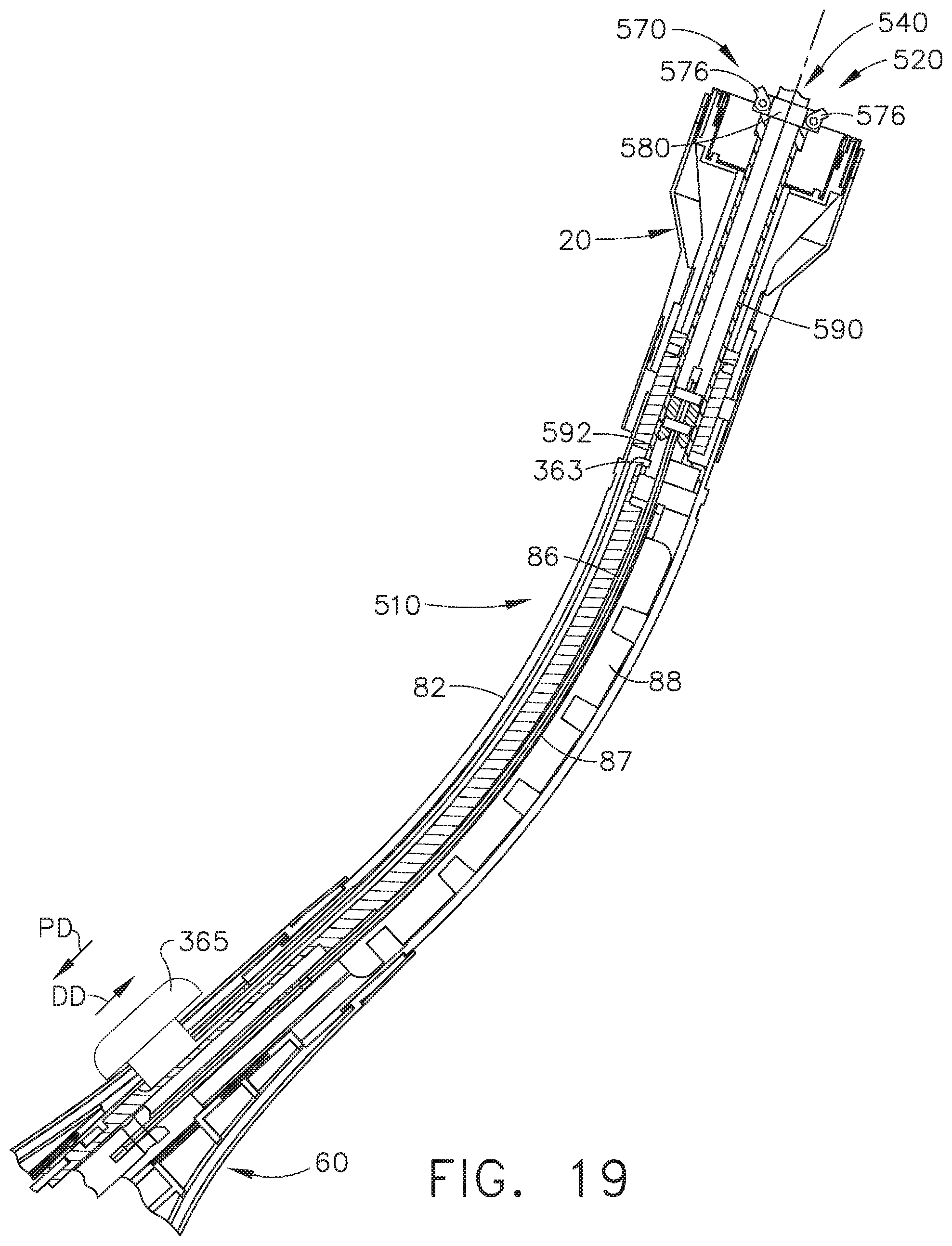
D00013
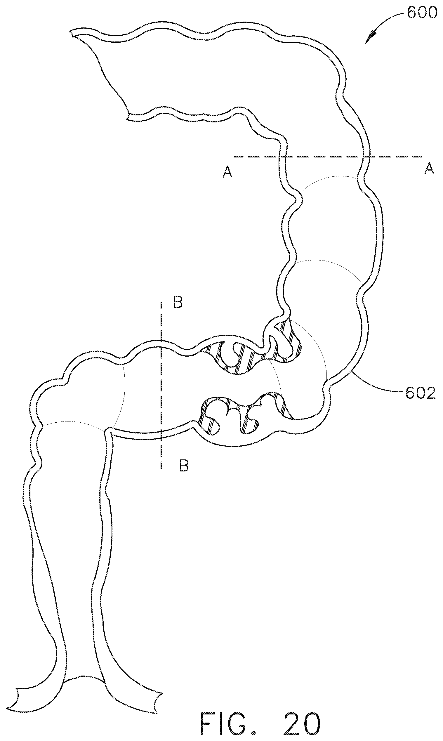
D00014

D00015

D00016

D00017
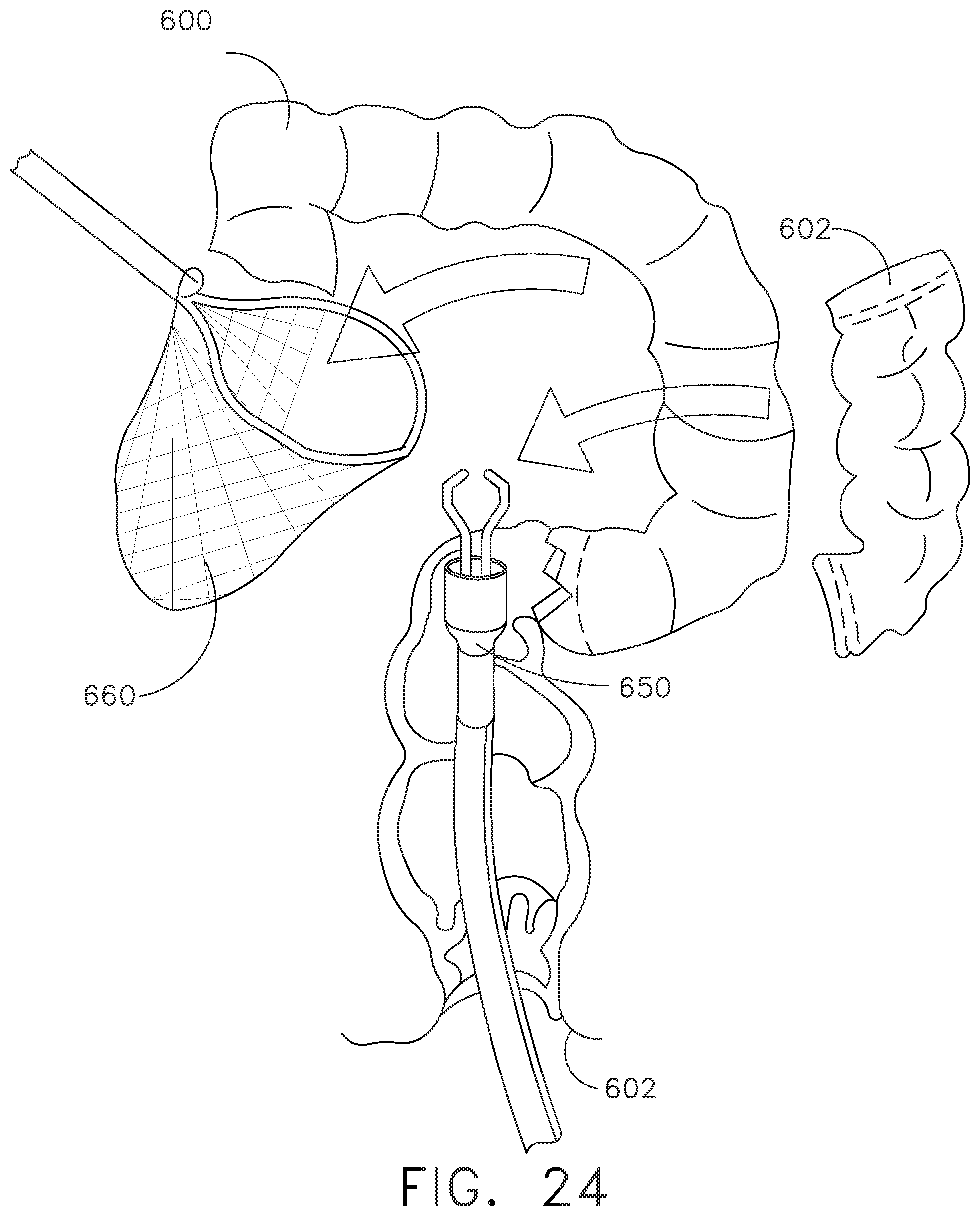
D00018

D00019
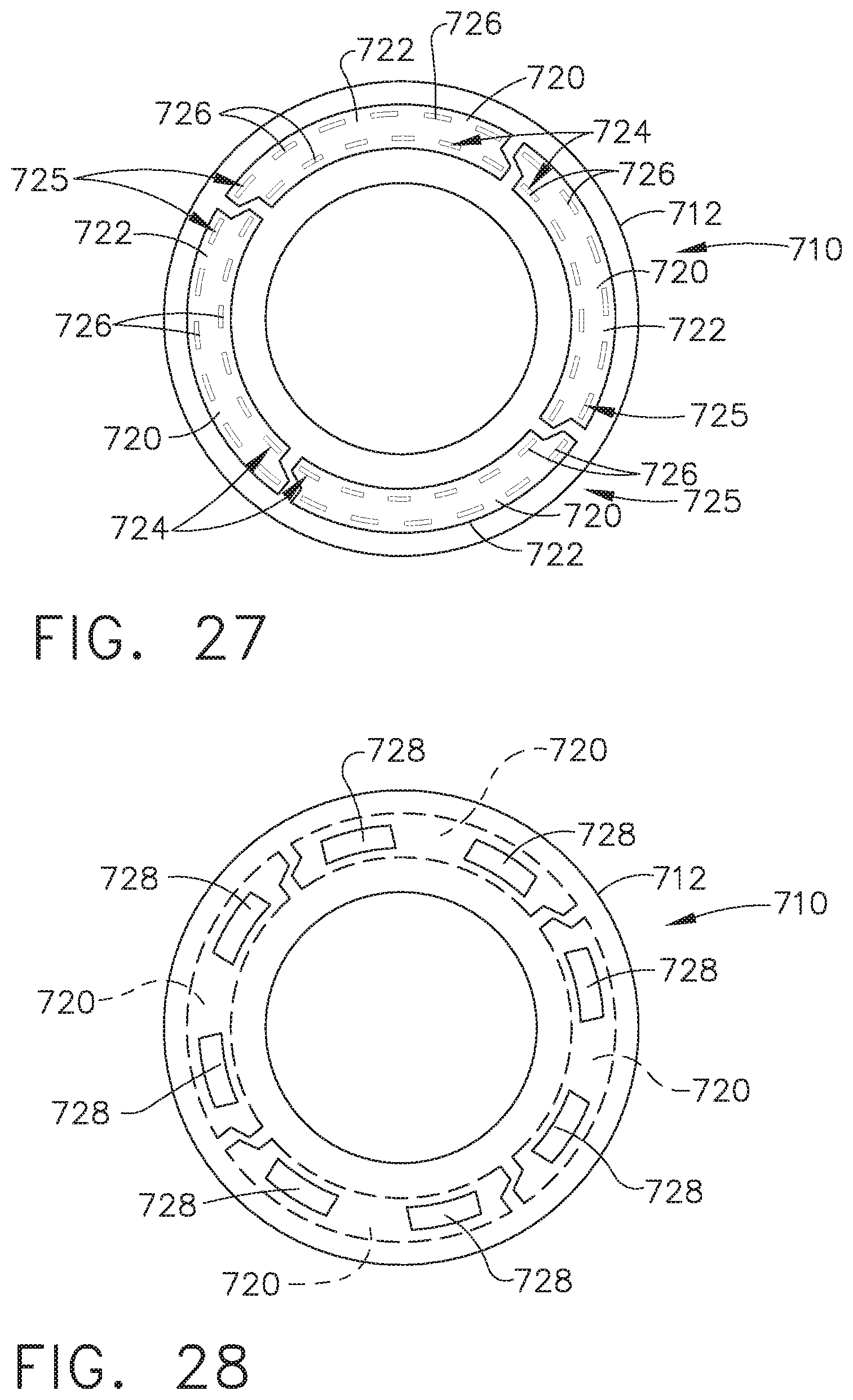
D00020

D00021

D00022

D00023

D00024

D00025
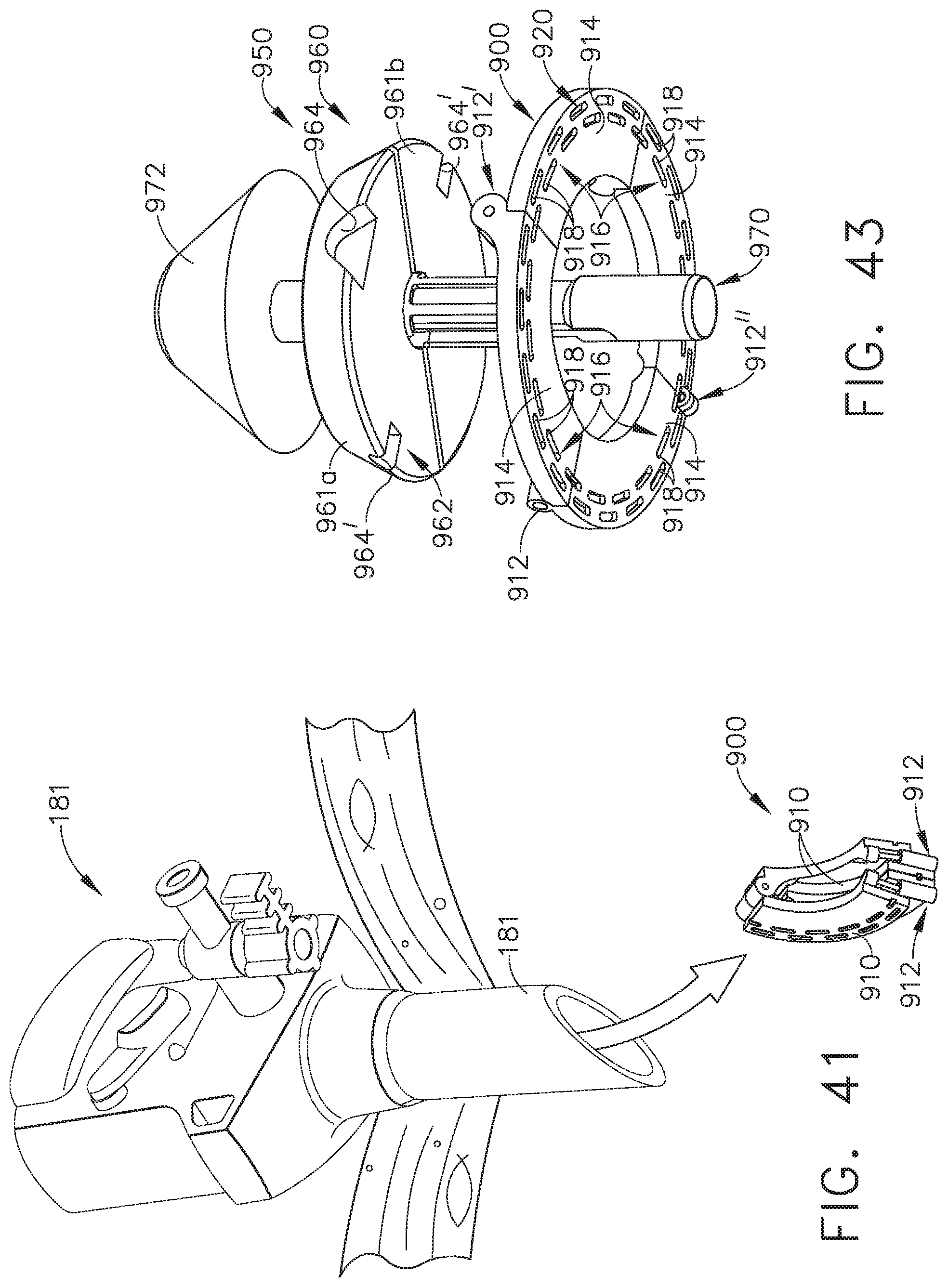
D00026

D00027

D00028

D00029
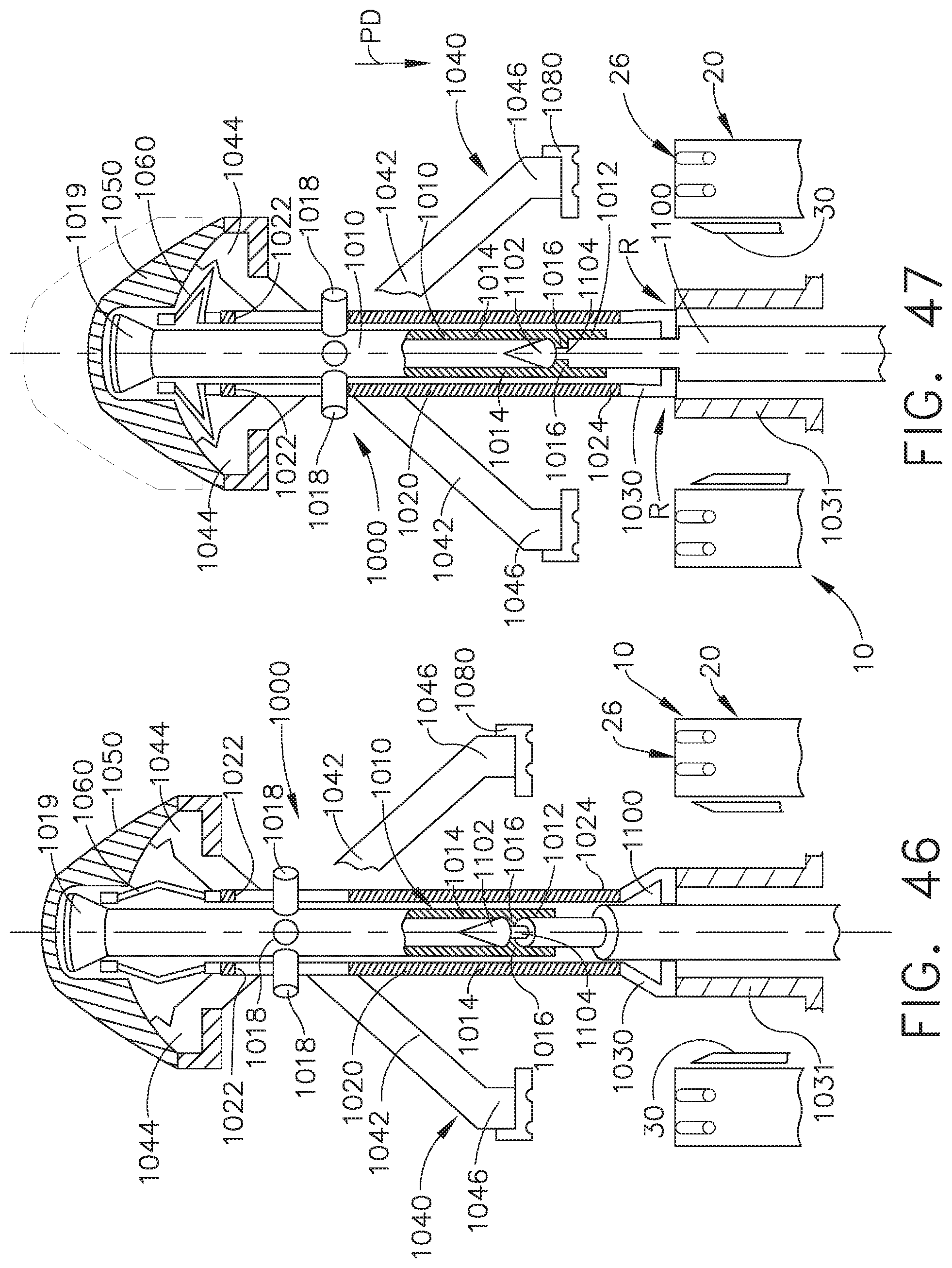
D00030

D00031
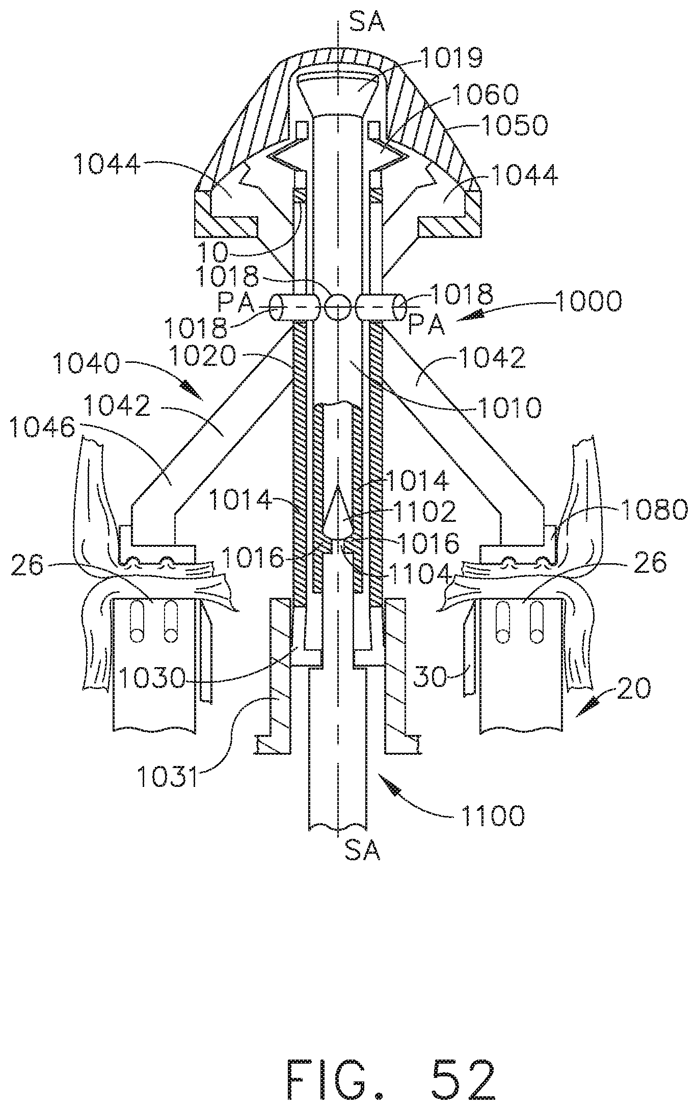
D00032

D00033

D00034
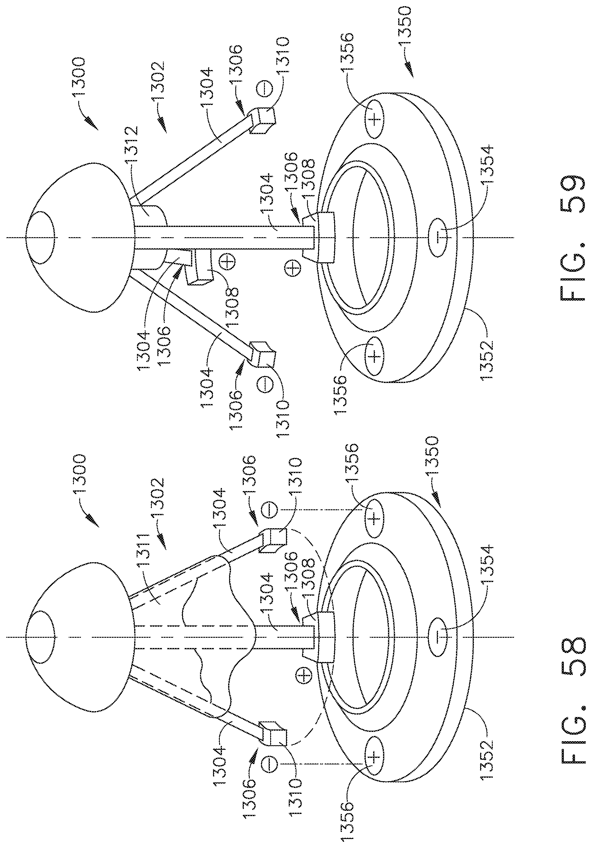
D00035
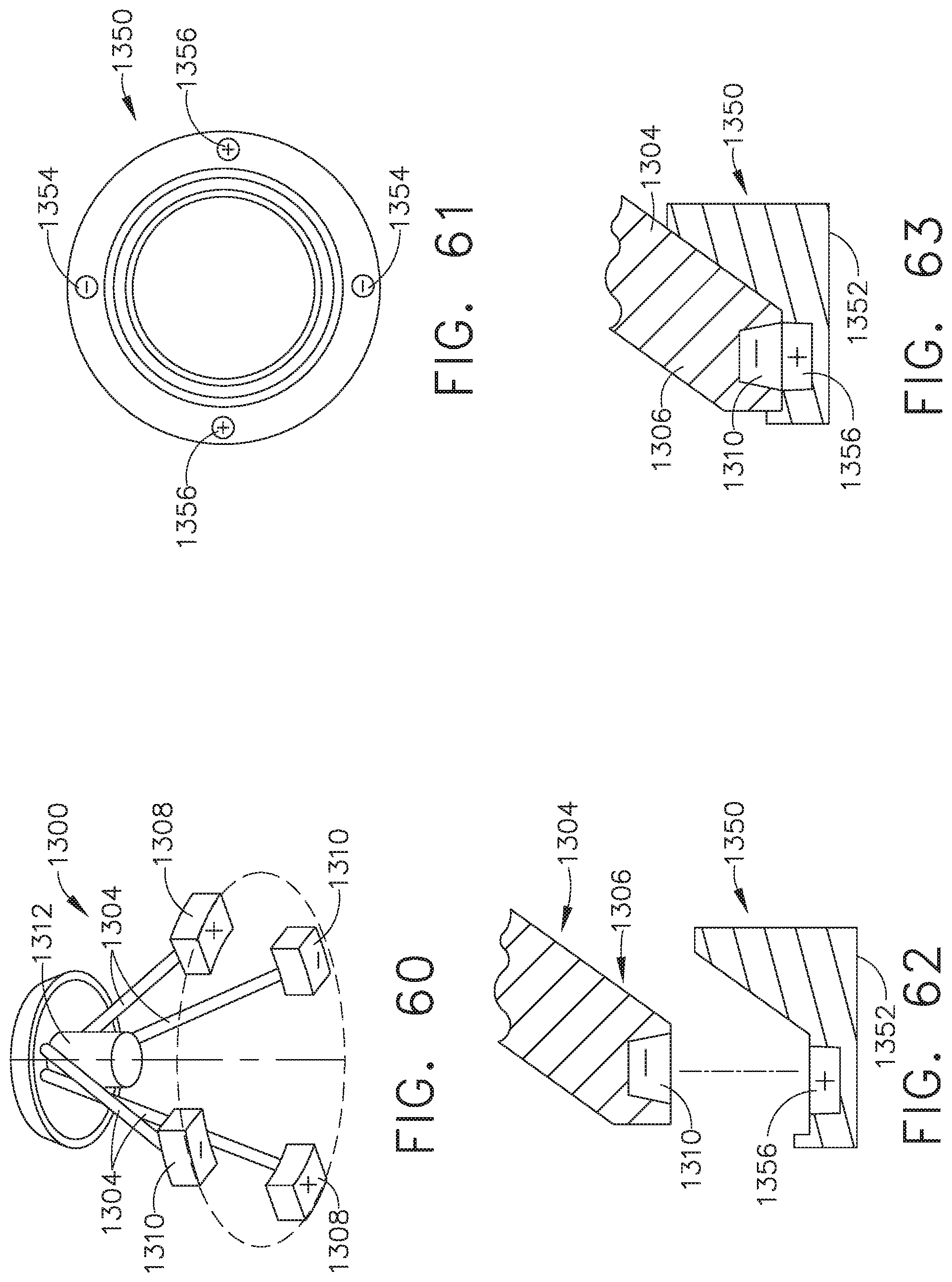
D00036
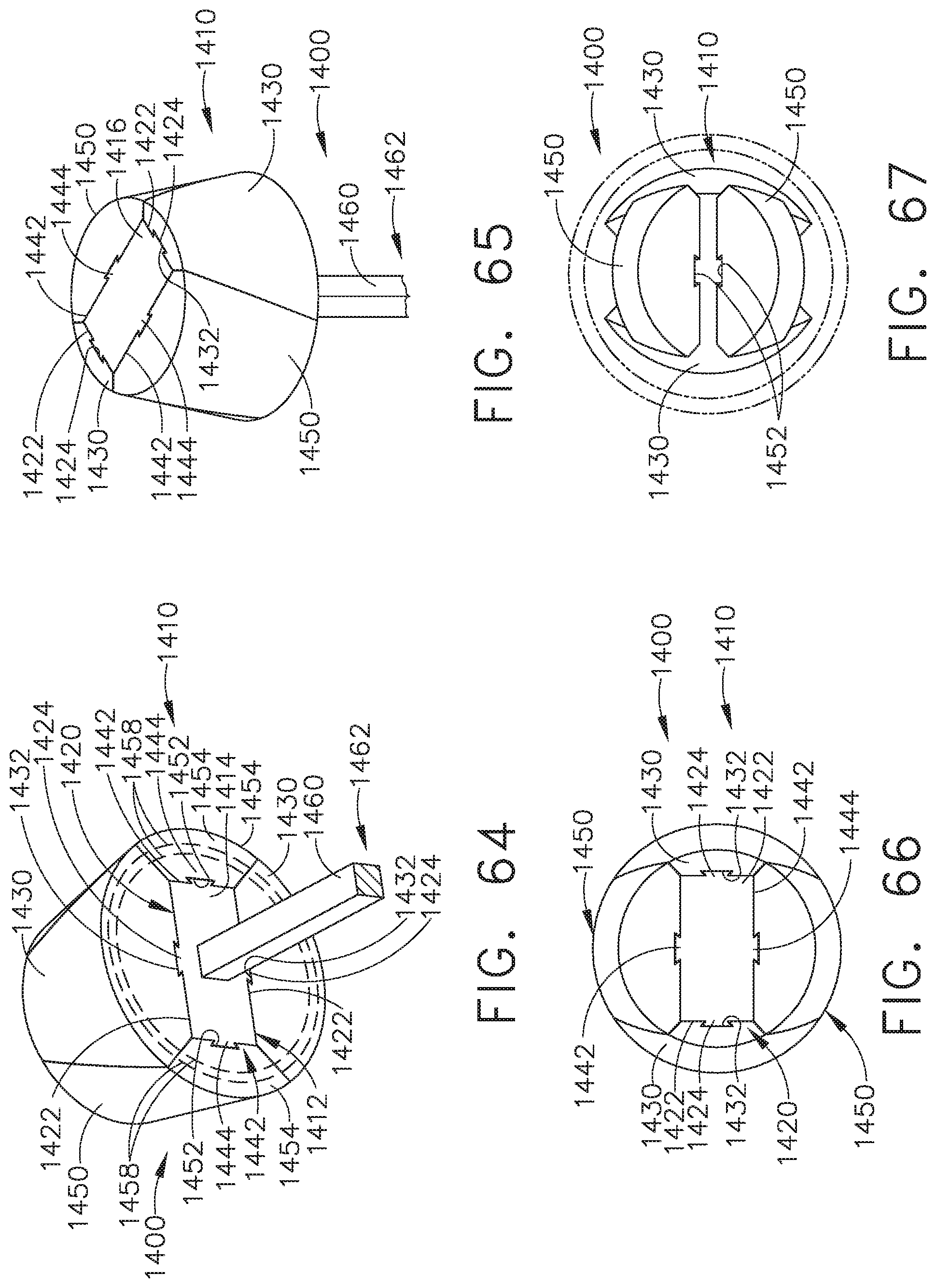
D00037
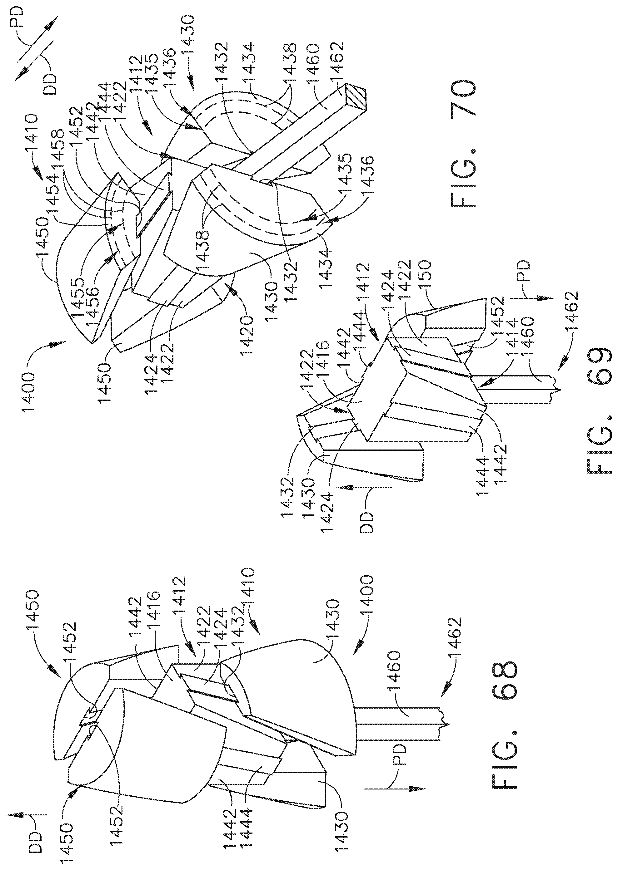
D00038

XML
uspto.report is an independent third-party trademark research tool that is not affiliated, endorsed, or sponsored by the United States Patent and Trademark Office (USPTO) or any other governmental organization. The information provided by uspto.report is based on publicly available data at the time of writing and is intended for informational purposes only.
While we strive to provide accurate and up-to-date information, we do not guarantee the accuracy, completeness, reliability, or suitability of the information displayed on this site. The use of this site is at your own risk. Any reliance you place on such information is therefore strictly at your own risk.
All official trademark data, including owner information, should be verified by visiting the official USPTO website at www.uspto.gov. This site is not intended to replace professional legal advice and should not be used as a substitute for consulting with a legal professional who is knowledgeable about trademark law.