Earpiece with wirelessly recharging battery
Boesen , et al.
U.S. patent number 10,587,943 [Application Number 15/643,606] was granted by the patent office on 2020-03-10 for earpiece with wirelessly recharging battery. This patent grant is currently assigned to BRAGI GmbH. The grantee listed for this patent is BRAGI GmbH. Invention is credited to Peter Vincent Boesen, Eric Christian Hirsch.


| United States Patent | 10,587,943 |
| Boesen , et al. | March 10, 2020 |
Earpiece with wirelessly recharging battery
Abstract
A wearable device includes a housing, a rechargeable battery disposed within the housing and a short range transceiver for near field communication disposed within the housing. The short range transceiver for near field communications comprises a core and a plurality of coil turns wrapped around the core to thereby form a coil. A charging circuit may electrically connected between the coil and the rechargeable battery and configured to charge the rechargeable battery using electromagnetic waves received by the coil.
| Inventors: | Boesen; Peter Vincent (Munchen, DE), Hirsch; Eric Christian (Munchen, DE) | ||||||||||
|---|---|---|---|---|---|---|---|---|---|---|---|
| Applicant: |
|
||||||||||
| Assignee: | BRAGI GmbH (Munchen,
DE) |
||||||||||
| Family ID: | 60910677 | ||||||||||
| Appl. No.: | 15/643,606 | ||||||||||
| Filed: | July 7, 2017 |
Prior Publication Data
| Document Identifier | Publication Date | |
|---|---|---|
| US 20180014104 A1 | Jan 11, 2018 | |
Related U.S. Patent Documents
| Application Number | Filing Date | Patent Number | Issue Date | ||
|---|---|---|---|---|---|
| 62360378 | Jul 9, 2016 | ||||
| Current U.S. Class: | 1/1 |
| Current CPC Class: | H02J 50/10 (20160201); H04R 1/1016 (20130101); H04R 1/1025 (20130101); H02J 50/90 (20160201); H04R 1/1041 (20130101); H04R 2420/07 (20130101) |
| Current International Class: | H04R 1/10 (20060101); H02J 50/10 (20160101); H02J 7/02 (20160101); H02J 50/90 (20160101); E21B 47/12 (20120101) |
| Field of Search: | ;381/74 ;340/853.1,854.6,854.8 |
References Cited [Referenced By]
U.S. Patent Documents
| 2325590 | August 1943 | Carlisle et al. |
| 2430229 | November 1947 | Kelsey |
| 3047089 | July 1962 | Zwislocki |
| D208784 | October 1967 | Sanzone |
| 3586794 | June 1971 | Michaelis |
| 3934100 | January 1976 | Harada |
| 3983336 | September 1976 | Malek et al. |
| 4069400 | January 1978 | Johanson et al. |
| 4150262 | April 1979 | Ono |
| 4334315 | June 1982 | Ono et al. |
| D266271 | September 1982 | Johanson et al. |
| 4375016 | February 1983 | Harada |
| 4588867 | May 1986 | Konomi |
| 4617429 | October 1986 | Bellafiore |
| 4654883 | March 1987 | Iwata |
| 4682180 | July 1987 | Gans |
| 4791673 | December 1988 | Schreiber |
| 4852177 | July 1989 | Ambrose |
| 4865044 | September 1989 | Wallace et al. |
| 4984277 | January 1991 | Bisgaard et al. |
| 5008943 | April 1991 | Arndt et al. |
| 5185802 | February 1993 | Stanton |
| 5191602 | March 1993 | Regen et al. |
| 5201007 | April 1993 | Ward et al. |
| 5201008 | April 1993 | Arndt et al. |
| D340286 | October 1993 | Seo |
| 5280524 | January 1994 | Norris |
| 5295193 | March 1994 | Ono |
| 5298692 | March 1994 | Ikeda et al. |
| 5343532 | August 1994 | Shugart |
| 5347584 | September 1994 | Narisawa |
| 5363444 | November 1994 | Norris |
| D367113 | February 1996 | Weeks |
| 5497339 | March 1996 | Bernard |
| 5606621 | February 1997 | Reiter et al. |
| 5613222 | March 1997 | Guenther |
| 5654530 | August 1997 | Sauer et al. |
| 5692059 | November 1997 | Kruger |
| 5721783 | February 1998 | Anderson |
| 5748743 | May 1998 | Weeks |
| 5749072 | May 1998 | Mazurkiewicz et al. |
| 5771438 | June 1998 | Palermo et al. |
| D397796 | September 1998 | Yabe et al. |
| 5802167 | September 1998 | Hong |
| D410008 | May 1999 | Almqvist |
| 5929774 | July 1999 | Charlton |
| 5933506 | August 1999 | Aoki et al. |
| 5949896 | September 1999 | Nageno et al. |
| 5987146 | November 1999 | Pluvinage et al. |
| 6021207 | February 2000 | Puthuff et al. |
| 6054989 | April 2000 | Robertson et al. |
| 6081724 | June 2000 | Wilson |
| 6084526 | July 2000 | Blotky et al. |
| 6094492 | July 2000 | Boesen |
| 6111569 | August 2000 | Brusky et al. |
| 6112103 | August 2000 | Puthuff |
| 6157727 | December 2000 | Rueda |
| 6167039 | December 2000 | Karlsson et al. |
| 6181801 | January 2001 | Puthuff et al. |
| 6208372 | March 2001 | Barraclough |
| 6230029 | May 2001 | Yegiazaryan et al. |
| 6275789 | August 2001 | Moser et al. |
| 6339754 | January 2002 | Flanagan et al. |
| D455835 | April 2002 | Anderson et al. |
| 6408081 | June 2002 | Boesen |
| 6424820 | July 2002 | Burdick et al. |
| D464039 | October 2002 | Boesen |
| 6470893 | October 2002 | Boesen |
| D468299 | January 2003 | Boesen |
| D468300 | January 2003 | Boesen |
| 6542721 | April 2003 | Boesen |
| 6560468 | May 2003 | Boesen |
| 6654721 | November 2003 | Handelman |
| 6664713 | December 2003 | Boesen |
| 6690807 | February 2004 | Meyer |
| 6694180 | February 2004 | Boesen |
| 6718043 | April 2004 | Boesen |
| 6738485 | May 2004 | Boesen |
| 6748095 | June 2004 | Goss |
| 6754358 | June 2004 | Boesen et al. |
| 6784873 | August 2004 | Boesen et al. |
| 6823195 | November 2004 | Boesen |
| 6852084 | February 2005 | Boesen |
| 6879698 | April 2005 | Boesen |
| 6892082 | May 2005 | Boesen |
| 6920229 | July 2005 | Boesen |
| 6952483 | October 2005 | Boesen et al. |
| 6987986 | January 2006 | Boesen |
| 7010137 | March 2006 | Leedom et al. |
| 7113611 | September 2006 | Leedom et al. |
| D532520 | November 2006 | Kampmeier et al. |
| 7136282 | November 2006 | Rebeske |
| 7203331 | April 2007 | Boesen |
| 7209569 | April 2007 | Boesen |
| 7215790 | May 2007 | Boesen et al. |
| D549222 | August 2007 | Huang |
| D554756 | November 2007 | Sjursen et al. |
| 7403629 | July 2008 | Aceti et al. |
| D579006 | October 2008 | Kim et al. |
| 7463902 | December 2008 | Boesen |
| 7508411 | March 2009 | Boesen |
| D601134 | September 2009 | Elabidi et al. |
| 7825626 | November 2010 | Kozisek |
| 7965855 | June 2011 | Ham |
| 7979035 | July 2011 | Griffin et al. |
| 7983628 | July 2011 | Boesen |
| D647491 | October 2011 | Chen et al. |
| 8095188 | January 2012 | Shi |
| 8108143 | January 2012 | Tester |
| 8140357 | March 2012 | Boesen |
| D666581 | September 2012 | Perez |
| 8300864 | October 2012 | Mullenborn et al. |
| 8406448 | March 2013 | Lin |
| 8436780 | May 2013 | Schantz et al. |
| D687021 | July 2013 | Yuen |
| 8719877 | May 2014 | VonDoenhoff et al. |
| 8774434 | July 2014 | Zhao et al. |
| 8831266 | September 2014 | Huang |
| 8891800 | November 2014 | Shaffer |
| 8994498 | March 2015 | Agrafioti et al. |
| D728107 | April 2015 | Martin et al. |
| 9013145 | April 2015 | Castillo et al. |
| 9037125 | May 2015 | Kadous |
| D733103 | June 2015 | Jeong et al. |
| 9081944 | July 2015 | Camacho et al. |
| 9510159 | November 2016 | Cuddihy et al. |
| D773439 | December 2016 | Walker |
| D775158 | December 2016 | Dong et al. |
| D777710 | January 2017 | Palmborg et al. |
| D788079 | May 2017 | Son et al. |
| 2001/0005197 | June 2001 | Mishra et al. |
| 2001/0027121 | October 2001 | Boesen |
| 2001/0043707 | November 2001 | Leedom |
| 2001/0056350 | December 2001 | Calderone et al. |
| 2002/0002413 | January 2002 | Tokue |
| 2002/0007510 | January 2002 | Mann |
| 2002/0010590 | January 2002 | Lee |
| 2002/0030637 | March 2002 | Mann |
| 2002/0046035 | April 2002 | Kitahara et al. |
| 2002/0057810 | May 2002 | Boesen |
| 2002/0076073 | June 2002 | Taenzer et al. |
| 2002/0118852 | August 2002 | Boesen |
| 2003/0002705 | January 2003 | Boesen |
| 2003/0065504 | April 2003 | Kraemer et al. |
| 2003/0100331 | May 2003 | Dress et al. |
| 2003/0104806 | June 2003 | Ruef et al. |
| 2003/0115068 | June 2003 | Boesen |
| 2003/0125096 | July 2003 | Boesen |
| 2003/0218064 | November 2003 | Conner et al. |
| 2004/0070564 | April 2004 | Dawson et al. |
| 2004/0160511 | August 2004 | Boesen |
| 2005/0017842 | January 2005 | Dematteo |
| 2005/0043056 | February 2005 | Boesen |
| 2005/0094839 | May 2005 | Gwee |
| 2005/0125320 | June 2005 | Boesen |
| 2005/0148883 | July 2005 | Boesen |
| 2005/0165663 | July 2005 | Razumov |
| 2005/0196009 | September 2005 | Boesen |
| 2005/0251455 | November 2005 | Boesen |
| 2005/0266876 | December 2005 | Boesen |
| 2006/0029246 | February 2006 | Boesen |
| 2006/0074671 | April 2006 | Farmaner et al. |
| 2006/0074808 | April 2006 | Boesen |
| 2006/0166715 | July 2006 | Engelen et al. |
| 2006/0166716 | July 2006 | Seshadri et al. |
| 2006/0220915 | October 2006 | Bauer |
| 2006/0258412 | November 2006 | Liu |
| 2008/0076972 | March 2008 | Dorogusker et al. |
| 2008/0090622 | April 2008 | Kim et al. |
| 2008/0146890 | June 2008 | LeBoeuf et al. |
| 2008/0254780 | October 2008 | Kuhl et al. |
| 2008/0255430 | October 2008 | Alexandersson et al. |
| 2008/0260169 | October 2008 | Reuss |
| 2008/0297349 | December 2008 | Leone |
| 2009/0003620 | January 2009 | McKillop et al. |
| 2009/0008275 | January 2009 | Ferrari et al. |
| 2009/0017881 | January 2009 | Madrigal |
| 2009/0073070 | March 2009 | Rofougaran |
| 2009/0097689 | April 2009 | Prest et al. |
| 2009/0105548 | April 2009 | Bart |
| 2009/0191920 | July 2009 | Regen et al. |
| 2009/0245559 | October 2009 | Boltyenkov et al. |
| 2009/0261114 | October 2009 | McGuire et al. |
| 2009/0296968 | December 2009 | Wu et al. |
| 2010/0033313 | February 2010 | Keady et al. |
| 2010/0203831 | August 2010 | Muth |
| 2010/0210212 | August 2010 | Sato |
| 2010/0320961 | December 2010 | Castillo et al. |
| 2011/0115429 | May 2011 | Toivola |
| 2011/0140844 | June 2011 | McGuire et al. |
| 2011/0239497 | October 2011 | McGuire et al. |
| 2011/0286615 | November 2011 | Olodort et al. |
| 2012/0057740 | March 2012 | Rosal |
| 2013/0316642 | November 2013 | Newham |
| 2013/0346168 | December 2013 | Zhou et al. |
| 2014/0079257 | March 2014 | Ruwe et al. |
| 2014/0106677 | April 2014 | Altman |
| 2014/0122116 | May 2014 | Smythe |
| 2014/0163771 | June 2014 | Demeniuk |
| 2014/0185828 | July 2014 | Helbling |
| 2014/0222462 | August 2014 | Shakil et al. |
| 2014/0235169 | August 2014 | Parkinson et al. |
| 2014/0270227 | September 2014 | Swanson |
| 2014/0270271 | September 2014 | Dehe et al. |
| 2014/0348367 | November 2014 | Vavrus et al. |
| 2015/0028996 | January 2015 | Agrafioti et al. |
| 2015/0110587 | April 2015 | Hori |
| 2015/0148989 | May 2015 | Cooper et al. |
| 2015/0245127 | August 2015 | Shaffer |
| 2016/0033280 | February 2016 | Moore et al. |
| 2016/0072558 | March 2016 | Hirsch et al. |
| 2016/0073189 | March 2016 | Linden et al. |
| 2016/0125892 | May 2016 | Bowen et al. |
| 2016/0360350 | December 2016 | Watson et al. |
| 2017/0064437 | March 2017 | Hviid et al. |
| 2017/0078780 | March 2017 | Qian et al. |
| 2017/0111726 | April 2017 | Martin et al. |
| 2017/0155992 | June 2017 | Perianu et al. |
| 204244472 | Apr 2015 | CN | |||
| 104683519 | Jun 2015 | CN | |||
| 104837094 | Aug 2015 | CN | |||
| 1469659 | Oct 2004 | EP | |||
| 1017252 | May 2006 | EP | |||
| 2903186 | Aug 2015 | EP | |||
| 2074817 | Apr 1981 | GB | |||
| 2508226 | May 2014 | GB | |||
| 2008103925 | Aug 2008 | WO | |||
| 2007034371 | Nov 2008 | WO | |||
| 2011001433 | Jan 2011 | WO | |||
| 2012071127 | May 2012 | WO | |||
| 2013134956 | Sep 2013 | WO | |||
| 2014046602 | Mar 2014 | WO | |||
| 2014043179 | Jul 2014 | WO | |||
| 2015061633 | Apr 2015 | WO | |||
| 2015110577 | Jul 2015 | WO | |||
| 2015110587 | Jul 2015 | WO | |||
| 2016032990 | Mar 2016 | WO | |||
Other References
|
Akkermans, "Acoustic Ear Recognition for Person Identification", Automatic Identification Advanced Technologies, 2005 pp. 219-223. cited by applicant . Announcing the $3,333,333 Stretch Goal (Feb. 24, 2014). cited by applicant . Ben Coxworth: "Graphene-based ink could enable low-cost, foldable electronics", "Journal of Physical Chemistry Letters", Northwestern University, (May 22, 2013). cited by applicant . Blain: "World's first graphene speaker already superior to Sennheiser MX400", htt://www.gizmag.com/graphene-speaker-beats-sennheiser-mx400/3166- 0, (Apr. 15, 2014). cited by applicant . BMW, "BMW introduces BMW Connected--The personalized digital assistant", "http://bmwblog.com/2016/01/05/bmw-introduces-bmw-connected-the-personali- zed-digital-assistant", (Jan. 5, 2016). cited by applicant . BRAGI is on Facebook (2014). cited by applicant . BRAGI Update--Arrival of Prototype Chassis Parts--More People--Awesomeness (May 13, 2014). cited by applicant . BRAGI Update--Chinese New Year, Design Verification, Charging Case, More People, Timeline(Mar. 6, 2015). cited by applicant . BRAGI Update--First Sleeves From Prototype Tool--Software Development Kit (Jun. 5, 2014). cited by applicant . BRAGI Update--Let's Get Ready to Rumble, a Lot to Be Done Over Christmas (Dec. 22, 2014). cited by applicant . BRAGI Update--Memories From April--Update on Progress (Sep. 16, 2014). cited by applicant . BRAGI Update--Memories from May--Update on Progress--Sweet (Oct. 13, 2014). cited by applicant . BRAGI Update--Memories From One Month Before Kickstarter--Update on Progress (Jul. 10, 2014). cited by applicant . BRAGI Update--Memories From the First Month of Kickstarter--Update on Progress (Aug. 1, 2014). cited by applicant . BRAGI Update--Memories From the Second Month of Kickstarter--Update on Progress (Aug. 22, 2014). cited by applicant . BRAGI Update--New People @BRAGI--Prototypes (Jun. 26, 2014). cited by applicant . BRAGI Update--Office Tour, Tour to China, Tour to CES (Dec. 11, 2014). cited by applicant . BRAGI Update--Status on Wireless, Bits and Pieces, Testing--Oh Yeah, Timeline(Apr. 24, 2015). cited by applicant . BRAGI Update--The App Preview, The Charger, The SDK, BRAGI Funding and Chinese New Year (Feb. 11, 2015). cited by applicant . BRAGI Update--What We Did Over Christmas, Las Vegas & CES (Jan. 19, 2014). cited by applicant . BRAGI Update--Years of Development, Moments of Utter Joy and Finishing What We Started(Jun. 5, 2015). cited by applicant . BRAGI Update--Alpha 5 and Back to China, Backer Day, on Track(May 16, 2015). cited by applicant . BRAGI Update--Beta2 Production and Factory Line(Aug. 20, 2015). cited by applicant . BRAGI Update--Certifications, Production, Ramping Up. cited by applicant . BRAGI Update--Developer Units Shipping and Status(Oct. 05, 2015). cited by applicant . BRAGI Update--Developer Units Started Shipping and Status (Oct. 19, 2015). cited by applicant . BRAGI Update--Developer Units, Investment, Story and Status(Nov. 2, 2015). cited by applicant . BRAGI Update--Getting Close(Aug. 6, 2015). cited by applicant . BRAGI Update--On Track, Design Verification, How It Works and What's Next(Jul. 15, 2015). cited by applicant . BRAGI Update--On Track, on Track and Gems Overview. cited by applicant . BRAGI Update--Status on Wireless, Supply, Timeline and Open House@BRAGI(Apr. 1, 2015). cited by applicant . BRAGI Update--Unpacking Video, Reviews on Audio Perform and Boy Are We Getting Close(Sep. 10, 2015). cited by applicant . Healthcare Risk Management Review, "Nuance updates computer-assisted physician documentation solution" (Oct. 20, 2016). cited by applicant . Hoyt et. al., "Lessons Learned from Implementation of Voice Recognition for Documentation in the Military Electronic Health Record System", The American Health Information Management Association (2017). cited by applicant . Hyundai Motor America, "Hyundai Motor Company Introduces a Health + Mobility Concept for Wellness in Mobility", Fountain Valley, Californa (2017). cited by applicant . International Search Report & Written Opinion, PCT/EP2016/070231 (dated Nov. 18, 2016). cited by applicant . Last Push Before the Kickstarter Campaign Ends on Monday 4pm CET (Mar. 28, 2014). cited by applicant . Nigel Whitfield: "Fake tape detectors, `from the stands` footie and UGH? Internet of Things in my set-top box"; http://www.theregister.co.uk/2014/09/24/ibc_round_up_object_audio_dlna_io- t/ (Sep. 24, 2014). cited by applicant . Staab, Wayne J., et al., "A One-Size Disposable Hearing Aid is Introduced", The Hearing Journal 53(4):36-41) Apr. 2000. cited by applicant . Stretchgoal--Its Your Dash (Feb. 14, 2014). cited by applicant . Stretchgoal--The Carrying Case for the Dash (Feb. 12, 2014). cited by applicant . Stretchgoal--Windows Phone Support (Feb. 17, 2014). cited by applicant . The Dash + The Charging Case & The BRAGI News (Feb. 21, 2014). cited by applicant . The Dash--A Word From Our Software, Mechanical and Acoustics Team + An Update (Mar. 11, 2014). cited by applicant . Update From BRAGI--$3,000,000--Yipee (Mar. 22, 2014). cited by applicant . Wikipedia, "Gamebook", https://en.wikipedia.org/wiki/Gamebook, Sep. 3, 2017, 5 pages. cited by applicant . Wikipedia, "Kinect", "https://en.wikipedia.org/wiki/Kinect", 18 pages, (Sep. 9, 2017). cited by applicant . Wikipedia, "Wii Balance Board", "https://en.wikipedia.org/wiki/Wii_Balance_Board", 3 pages, (Jul. 20, 2017). cited by applicant. |
Primary Examiner: Monikang; George C
Attorney, Agent or Firm: Goodhue, Coleman & Owens, P.C.
Parent Case Text
PRIORITY STATEMENT
The present application claims priority to U.S. Provisional Application No. 62/360,378, filed Jul. 9, 2016, hereby incorporated by reference in its entirety.
Claims
What is claimed is:
1. A wearable device, comprising: a housing; a rechargeable battery disposed within the housing; a short-range transceiver for near field communication disposed within the housing and configured to send and receive audio; wherein the short-range transceiver for near field communications comprises a core and a plurality of coil turns wrapped around the core to thereby form a coil; a charging circuit electrically connected between the coil and the rechargeable battery and configured to charge the rechargeable battery using electromagnetic waves received by the coil.
2. The wearable device of claim 1 wherein the wearable device is an earpiece.
3. The wearable device of claim 2 wherein the core is mounted at a posterosuperior portion of the wearable device.
4. The wearable device of claim 1 wherein the core comprises ferrite.
5. The wearable device of claim 1 wherein the core comprises a ferrite sheet magnetic shield spacer wrapped around the rechargeable battery.
6. The wearable device of claim 1 further comprising a switch operatively connected to the charging circuit to selectively control operation of the charging circuit.
7. The wearable device of claim 1 wherein the short-range transceiver is a near field magnetic induction (NFMI) transceiver.
8. The wearable device of claim 1 wherein the wearable device is configured to determine if the wearable device is positioned within an ear of a user.
9. The wearable device of claim 1 wherein the wearable device is configured to determine if the wearable device is positioned on a charging surface.
10. The wearable device of claim 9 further comprising a switch operatively connected to the charging circuit to selectively control operation of the charging circuit and wherein the wearable is configured to activate the charging circuit if the wearable device determines that the wearable device is not positioned within an ear of a user and further determines that the wearable device is positioned at a charging surface.
11. A system comprising: a first wearable device comprises a housing, a short range transceiver for near field communication and configured to send and receive audio disposed within the housing, wherein the short range transceiver for near field communications comprises a core and a plurality of coil turns wrapped around the core to thereby form a coil, and a charging circuit electrically connected between the coil and the rechargeable battery and configured to charge the rechargeable battery using electromagnetic waves received by the coil; a charging surface comprising a plurality of source coils for operative communication with the coil of the first wearable device to transfer electromagnetic energy to the first wearable device to recharge the rechargeable battery of the first wearable device.
12. The system of claim 11 further comprising a second wearable device comprising a housing, a short range transceiver for near field communication disposed within the housing, wherein the short range transceiver for near field communications comprises a core and a plurality of coil turns wrapped around the core to thereby form a coil, and a charging circuit electrically connected between the coil and the rechargeable battery and configured to charge the rechargeable battery using electromagnetic waves received by the coil.
13. The system of claim 11 wherein the first wearable device is an earpiece.
14. The system of claim 13 wherein the short-range transceiver is a near field magnetic induction transceiver.
15. The system of claim 11 wherein the core is mounted at a posterosuperior portion of the wearable device.
16. The system of claim 11 wherein the core comprises ferrite.
17. The system of claim 11 wherein the core comprises a ferrite sheet magnetic shield spacer wrapped around the rechargeable battery.
18. The system of claim 11 further comprising a switch operatively connected to the charging circuit to selectively control operation of the charging circuit.
19. A method of charging a wearable device, the method comprising: receiving audio communications using a coil when the wearable device is in a first mode of operation; and charging a rechargeable battery of the wearable device when the wearable device is in a second mode of operation; wherein the wearable device comprises a housing, a rechargeable battery disposed within the housing, a short range transceiver for near field communication disposed within the housing, wherein the short range transceiver for near field communications comprises a core and a plurality of coil turns wrapped around the core to thereby form the coil, and a charging circuit electrically connected between the coil and the rechargeable battery and configured to charge the rechargeable battery using electromagnetic waves received by the coil, and the method further comprising: switching to the first mode of operation if the wearable device detects it is positioned within an ear of a user; switching to the second mode of operation if the wearable device detects it is not positioned within the ear of the user and is positioned at one or more charging coils; and wherein the one or more charging coils are associated with a charging surface.
Description
FIELD OF THE INVENTION
The present invention relates to wireless earpieces. More particularly, but not exclusively, the present invention relates to wirelessly recharging earpieces.
BACKGROUND OF THE ART
The earpiece may one day become one of the most widely used and powerful wearable devices available. However, one of the problems with earpieces relates to battery consumption and use. Where the earpiece provides complicated processing or audio processing, has multiple sensors, and multiple transceivers, and produces audio output, battery consumption becomes an issue. Therefore, any onboard batteries would need to be either replaced or recharged, with recharging being preferred.
However, where batteries are to recharged, additional constraints on the design of the earpiece may be imposed such as the inclusion of a connector for recharging that is sufficiently durable and easy to use. Such a connector may take space that could otherwise be used to improve functionality of the earpiece. In addition, earpieces which are sized and shaped to fit within the external auditory canals of users may have relatively awkward and inconvenient shapes. Thus, not only does a connector on the earpiece take space, but the earpiece will also have to mate with another connector of a power source. It may be burdensome or inconvenient for a user to charge one or more earpieces in this manner.
Another issue is that if the earpiece is intended to be waterproof or water resistant, this may further constrain the design of the earpiece where connectors are used for recharging batteries.
What is needed are earpieces are related methods which allow for wireless recharging of the batteries contained therein.
SUMMARY OF THE INVENTION
Therefore it is a primary object, feature, or advantage of the present invention to improve over the state of the art.
It is a further object, feature, or advantage of the present invention to provide for an improved wearable device.
It is a still further object, feature, or advantage of the present invention to provide a wireless earpiece which is configured to permit wireless recharging.
Another object, feature, or advantage of the present invention is to provide a wireless earpiece which includes a coil which may be used for multiple purposes including both communications and re-charging.
Yet another object, feature, or advantage of the present invention is to provide a wireless earpiece which is easy and convenient for users to use and recharge.
One of these and/or other objects, features, or advantages of the present invention will become apparent from the specification and claims that follow. It is to be understood that different embodiments are disclosed herein and that no embodiment need meet each and every object, feature, or advantage as set forth herein. Different embodiments may have different objects, features, or advantages.
According to one aspect a wearable device includes a housing, a rechargeable battery disposed within the housing, and a short range transceiver for near field communication disposed within the housing. The short range transceiver for near field communications may include a core and a plurality of coil turns wrapped around the core to thereby form a coil. The wearable device may also include a charging circuit electrically connected between the coil and the rechargeable battery and configured to charge the rechargeable battery using electromagnetic waves received by the coil. The wearable device may be an earpiece. The wearable device may include a switch operatively connected to the charging circuit to selectively control operation of the charging circuit. The short range transceiver may be a near field magnetic induction (NFMI) transceiver. The wearable device may be configured to determine if the wearable device is positioned within an ear of a user and may be configured to determine if the wearable device is positioned on a charging surface.
According to another aspect, a system includes a first wearable device comprises a housing, a short range transceiver for near field communication disposed within the housing, wherein the short range transceiver for near field communications comprises a core and a plurality of coil turns wrapped around the core to thereby form a coil, and a charging circuit electrically connected between the coil and the rechargeable battery and configured to charge the rechargeable battery using electromagnetic waves received by the coil. The system also includes a charging surface comprising a plurality of source coils for operative communication with the coil of the first wearable device to transfer electromagnetic energy to the first wearable device to recharge the rechargeable battery of the first wearable device. The system may further include a second wearable device comprising a housing, a short range transceiver for near field communication disposed within the housing, wherein the short range transceiver for near field communications comprises a core and a plurality of coil turns wrapped around the core to thereby form a coil, and a charging circuit electrically connected between the coil and the rechargeable battery and configured to charge the rechargeable battery using electromagnetic waves received by the coil. The first and second wearable devices may be earpieces.
According to another aspect, a method of charging a wearable device may be provided. The method may include receiving communications using a coil when the wearable device is in a first mode of operation and charging a rechargeable battery of the wearable device when the wearable device is in a second mode of operation. The wearable device may include a housing, a rechargeable battery disposed within the housing, a short range transceiver for near field communication disposed within the housing, wherein the short range transceiver for near field communications comprises a core and a plurality of coil turns wrapped around the core to thereby form the coil, and a charging circuit electrically connected between the coil and the rechargeable battery and configured to charge the rechargeable battery using electromagnetic waves received by the coil. The method may include switching to the first mode of operation if the wearable device detects it is positioned within an ear of a user. The method may include switching to the second mode of operation if the wearable device detects it is not positioned within the ear of the user and is positioned at one or more charging coils. The one or more charging coils may be associated with a charging surface.
BRIEF DESCRIPTION OF THE DRAWINGS
FIG. 1 illustrates one example of a system including two wearable devices in the form of left and right ear pieces which bi-directionally communicate with each other.
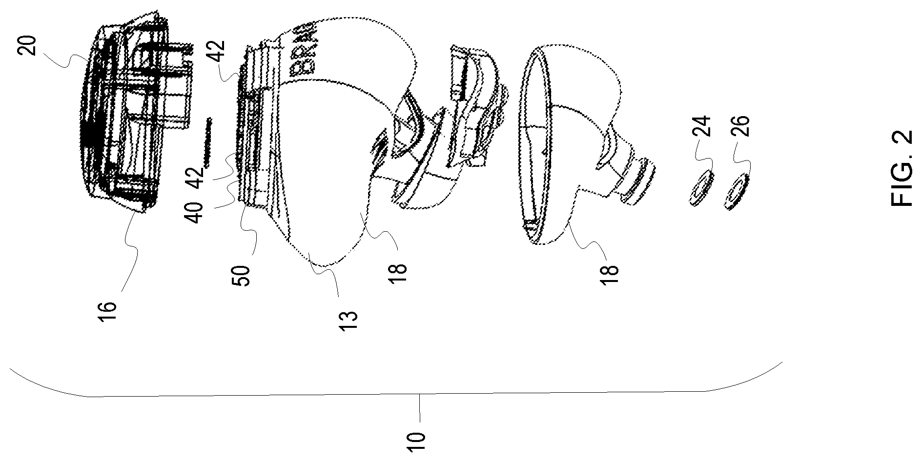
FIG. 2 is an exploded view of a wearable device.
FIG. 3 illustrates a printed circuit board of the wearable device positioned relative to an induction circuit/antenna.
FIG. 4 illustrates a core.
FIG. 5 illustrates a core with coil turns thereon.
FIG. 6 illustrates a set of earpiece wearable devices at or on a charging surface.
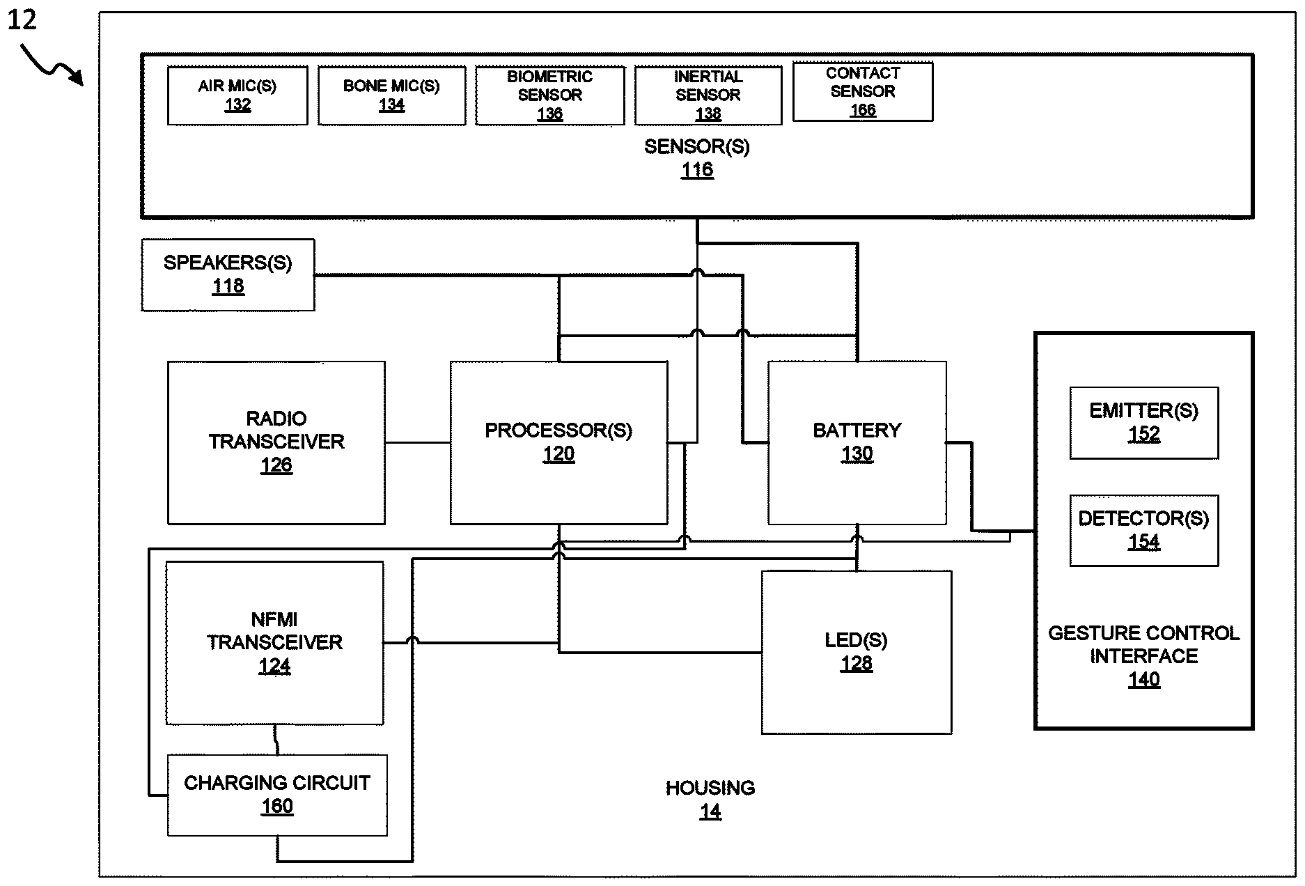
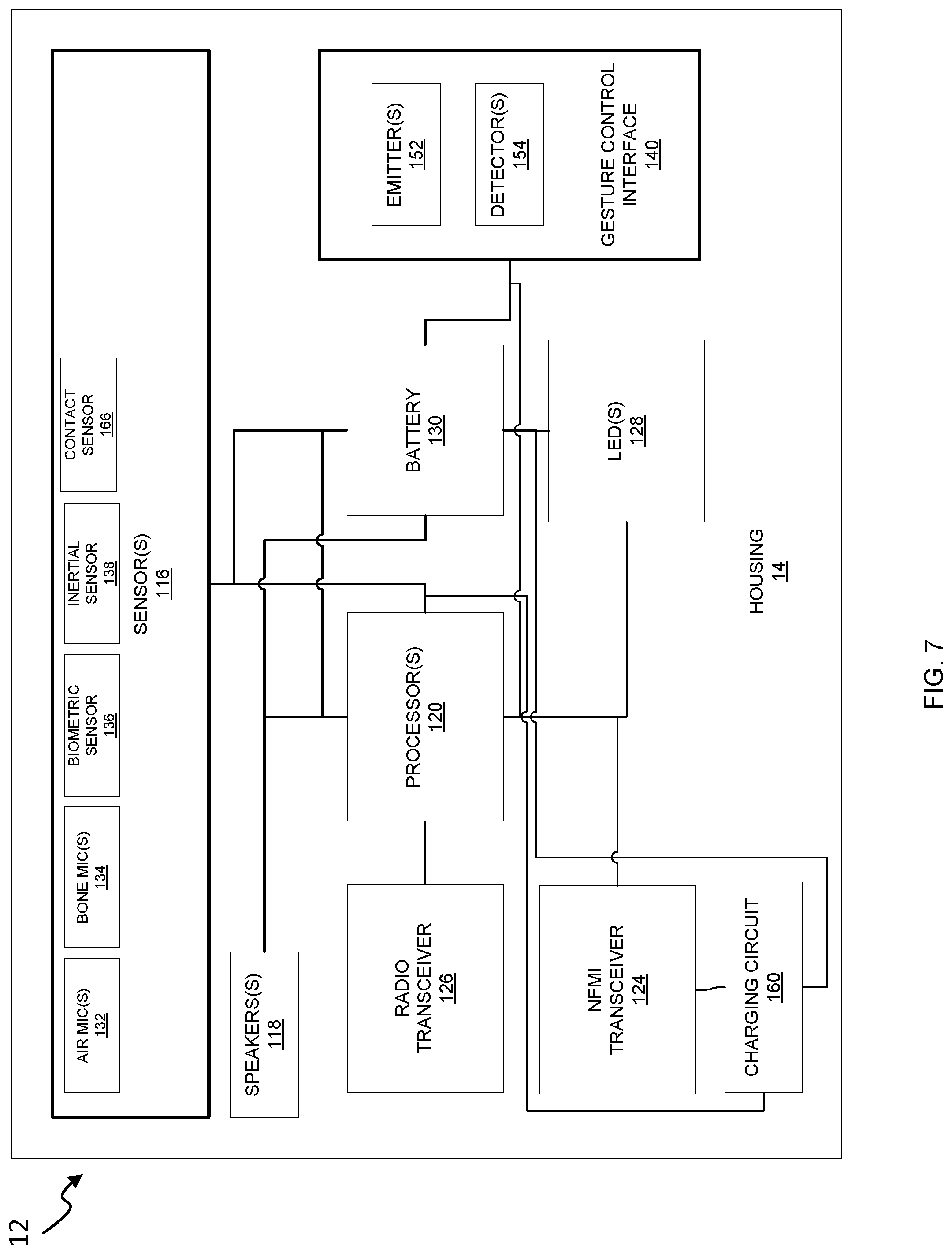
FIG. 7 illustrates one example of a block diagram of an earpiece.
DETAILED DESCRIPTION
The present invention relates to a wearable device such as an earpiece which uses a coil for both communications and recharging of a battery. Although generally described herein with respect to a near field magnetic induction (NFMI) antenna for use in an ear piece within a set of ear pieces, it is to be understood that the present invention is not limited to that specific application and may be used as an antenna for induction in other types of devices including other types of wearable devices.
FIG. 1 illustrates one example of a system 10 which includes a first wearable device 10A in the form of an ear piece and a second wearable device 10B also in the form of an ear piece, each having an ear piece housing 12 with a central portion 13 with an upper portion 16 and a lower portion 18. A light guide assembly 20 is shown operatively connected to the housing to provide for selective illumination to provide feedback to a user. FIG. 2 provides an exploded view of the wearable device 10A. A waterproof pad 24 and protection mesh 26 are shown. In addition in the central or main portion 13 of the wearable device 10A a printed circuit board 40 is shown with a plurality of electronic components 42 mounted thereto. The plurality of electronic components 42 may include a short range transceiver configured for far field communications such as a wireless radio such as a Bluetooth transceiver, a Wi-Fi transceiver, an ultra-wideband (UWB), or other type of transceiver. A core 50 is mounted at an edge or perimeter of the printed circuit board 40. The core 50 is preferably mounted at a posterosuperior portion of the wearable device 10A.
The system 10 allows for near field communication of audio channels between the left and right-sided wearable devices 10A, 10B. Other types of data may also be communicated between the left and right-sided wearable devices 10A, 10B if desired including sensor information or other data.
FIG. 3 illustrates another view of the printed circuit board 40 with electronic components 42. A core 50 is shown mounted at an edge or perimeter of the printed circuit board 40. The printed circuit board is generally planar. Note that the core 50 is mounted perpendicularly or orthogonally to the top surface of the printed circuit board 40 and the plurality of components 42 mounted thereto. Positioning the core 50 in this relationship provides for reducing electromagnetic interference. The core 50 may be formed of a ferrite material. For example, the core 50 may be a ferrite sheet magnetic spacer. As shown in FIG. 4, where the core 50 is a ferrite sheet magnetic spacer 52, the core 50 may be positioned over or wrapped around a battery 54. As shown in FIG. 5, a plurality of coil turns 60 may be wrapped around the core 50.
In one embodiment NFMI may be used for the communication and audio channels between the left and right sided wearable devices. Placement of the coil at the perimeter of the wearable improves the electromagnetic field, avoiding degradation from adjacent onboard electronics. This allowed for optimal placement of the magnetic field for transmission and reception between the left and right wearable. The preferred embodiment allows for precise positioning within the device for optimal orientation for the electromagnetic field. Further, the preferred embodiment also allows for an NFMI antenna that is sufficiently powerful for the expected tasks, is straightforward in its manufacturing and assembly.
FIG. 6 illustrates a system which includes a left earpiece 10A and a right ear piece 10B. The earpieces are positioned on or at a charging surface 80. The charging surface 80 may include one or more source coils 82. The source coils 82 may be powered in any number of ways. The source coils 82 are in operative communication with the coils of the earpieces 10A, 10B in order to transfer electromagnetic energy from the source coils to the coils of the earpieces 10A, 10B in order to recharge batteries disposed within the earpieces. Instead of a flat charging surface, earpieces may be positioned within a case of any number of styles or shapes which allow for the source coils 82 to be sufficiently close to the coils of the earpieces 10A.
FIG. 7 is a block diagram illustrating one example of an earpiece 12. One or more sensors 116 are present within the earpiece 12. The one or more sensors may include an air microphone 132, a bone microphone 134, a biometric sensor 136 such as a pulse oximeter, temperature sensor or other type of sensor, an inertial sensor 138, and a contact sensor 166. Although representative examples of sensors are shown and described it is to be understood that there may be multiple sensors of the same type and any number of additional types of sensors may be present within the earpiece. One or more speakers 118 may also be present. One or more processors 120 are shown. The various sensors 116, speakers 118, radio transceiver 126, NFMI transceiver 124, LEDs 128, may be operatively connected to the one or more processors. A gesture control interface 140 may also be present which may include one or more emitters 152 and detectors 154 which are also operatively connected to one or more processors 120. A battery 130 may also be present. A charging circuit 160 may also be operatively connected to one or more processors 120 and the battery 130. The charging circuit 160 may be operatively connected to the same coil which forms a part of the NFMI transceiver 124.
The earpiece may be configured to determine if the earpiece is positioned within an ear of a user or otherwise in use by a user of if the earpiece is positioned on a recharging surface. These determinations may be made in various ways. For example, to determine if the earpiece includes a physiological sensor or biometric sensor 136 such as a pulse oximeter then if there is pulse reading the earpiece may be considered to be within the ear of the user. In addition, or alternatively, if the earpiece includes an accelerometer or other inertial sensor 138 the position of the earpiece may be used to determine if the ear piece is within the ear of the user. One or more contact sensors 166 may be used to determine if the earpiece is positioned within the earpiece. Sounds may be emitted from a speaker 118 within the external auditory canal of a user and sensed with a microphone 132 at the external auditory canal of a user, including sub-auditory sounds to determine if the earpiece is within the external auditory canal of the user. Any number of other sensors and methodologies may be used to determine if the earpiece is within the external auditory canal of a user. Any number of other methods may be used including asking the user.
The earpiece may also be configured to determine if it positioned on the recharging surface. For example, if it is determined that the earpiece is not within the ear and voltage levels associated with the coil correlate with known levels associated with the earpiece being positioned on the recharging surface then it may be determined that the earpiece is on the recharging surface. Once it is known that the earpiece is not within the ear and that the earpiece is positioned on the recharging surface then a switch may be activated to allow the charging circuit to harvest the electromagnetic energy from the coil in order to recharge the battery.
Therefore, a wearable device has been shown and described and a system including multiple ear pieces which communicate with one another and also allow for recharging of batteries using the same coils. It is to be understood that the present invention contemplates numerous variations, options, and alternatives. The present invention is not to be limited to the specific embodiments and examples set forth herein.
* * * * *
References
D00000
D00001
D00002
D00003
D00004
D00005
D00006
D00007
XML
uspto.report is an independent third-party trademark research tool that is not affiliated, endorsed, or sponsored by the United States Patent and Trademark Office (USPTO) or any other governmental organization. The information provided by uspto.report is based on publicly available data at the time of writing and is intended for informational purposes only.
While we strive to provide accurate and up-to-date information, we do not guarantee the accuracy, completeness, reliability, or suitability of the information displayed on this site. The use of this site is at your own risk. Any reliance you place on such information is therefore strictly at your own risk.
All official trademark data, including owner information, should be verified by visiting the official USPTO website at www.uspto.gov. This site is not intended to replace professional legal advice and should not be used as a substitute for consulting with a legal professional who is knowledgeable about trademark law.