Systems and methods for manipulating medical devices
Look , et al. Feb
U.S. patent number 10,561,440 [Application Number 15/256,488] was granted by the patent office on 2020-02-18 for systems and methods for manipulating medical devices. This patent grant is currently assigned to Vesatek, LLC. The grantee listed for this patent is VESATEK, LLC. Invention is credited to Bradley S. Culbert, David M. Look.


View All Diagrams
| United States Patent | 10,561,440 |
| Look , et al. | February 18, 2020 |
Systems and methods for manipulating medical devices
Abstract
A method for treating a patient having thrombus includes providing a manipulation device including a housing configured to be supported by the hand of a user and having a distal and proximal end, a drive system disposed within the housing, and configured to rotate a rotation member, an engagement member coupled to the rotation member and configured to be removably coupled to an elongate medical device, an activation member carried by the housing such that it can be operated by at least a portion of the hand of the user when the housing is supported by the hand of the user, the drive system configured to apply motive force to the engagement member, securing an elongate member to the engagement member, introducing at least the distal end of the elongate member into a blood vessel adjacent a thrombus, operating the activation member to cause at least some rotation of the rotation member, which in turn causes at least some rotation of the distal end of the elongate member at or near the thrombus, and aspirating at least some of the thrombus with an aspiration catheter.
| Inventors: | Look; David M. (Newport Beach, CA), Culbert; Bradley S. (Tustin, CA) | ||||||||||
|---|---|---|---|---|---|---|---|---|---|---|---|
| Applicant: |
|
||||||||||
| Assignee: | Vesatek, LLC (Irvine,
CA) |
||||||||||
| Family ID: | 58188622 | ||||||||||
| Appl. No.: | 15/256,488 | ||||||||||
| Filed: | September 2, 2016 |
Prior Publication Data
| Document Identifier | Publication Date | |
|---|---|---|
| US 20170065396 A1 | Mar 9, 2017 | |
Related U.S. Patent Documents
| Application Number | Filing Date | Patent Number | Issue Date | ||
|---|---|---|---|---|---|
| 62214192 | Sep 3, 2015 | ||||
| 62286429 | Jan 24, 2016 | ||||
| Current U.S. Class: | 1/1 |
| Current CPC Class: | A61B 17/22 (20130101); A61B 17/320758 (20130101); A61B 17/32037 (20130101); A61B 2017/00734 (20130101); A61B 2017/22044 (20130101); A61B 2017/00469 (20130101); A61B 2017/00017 (20130101); A61B 2017/00398 (20130101); A61B 2017/22049 (20130101); A61B 2217/007 (20130101); A61B 2017/22079 (20130101); A61B 2217/005 (20130101); A61B 2017/22094 (20130101); A61B 2017/00685 (20130101); A61B 2017/00367 (20130101); A61B 2017/22038 (20130101); A61B 2017/22042 (20130101) |
| Current International Class: | A61B 17/3207 (20060101); A61B 17/3203 (20060101) |
References Cited [Referenced By]
U.S. Patent Documents
| 1114268 | October 1914 | Kells |
| 1148093 | July 1915 | Kells |
| 2804075 | August 1957 | Borden |
| 3429313 | February 1969 | Romanelli |
| 3631847 | January 1972 | Hobbs, II |
| 3693613 | September 1972 | Kelman |
| 3707967 | January 1973 | Kitrilakis et al. |
| 3748435 | July 1973 | Reynolds |
| 3847140 | November 1974 | Ayella |
| 3916892 | November 1975 | Latham, Jr. |
| 3930505 | January 1976 | Wallach |
| 3955573 | May 1976 | Hansen et al. |
| 4030503 | June 1977 | Clark, III |
| 4299221 | November 1981 | Phillips et al. |
| 4465470 | August 1984 | Keiman |
| 4574812 | March 1986 | Arkans |
| 4638539 | January 1987 | Palmer |
| 4690672 | September 1987 | Veltrup |
| 4700705 | October 1987 | Kensey et al. |
| 4728319 | March 1988 | Masch |
| 4747821 | May 1988 | Kensey et al. |
| 4790813 | December 1988 | Kensey |
| 4832685 | May 1989 | Haines |
| 4842579 | June 1989 | Shiber |
| 4854325 | August 1989 | Stevens |
| 4857046 | August 1989 | Stevens et al. |
| 4883458 | November 1989 | Shiber |
| 4883467 | November 1989 | Franetzki et al. |
| 4886490 | December 1989 | Shiber |
| 4894051 | January 1990 | Shiber |
| 4898574 | February 1990 | Uchiyama et al. |
| 4957482 | September 1990 | Shiber |
| 4979939 | December 1990 | Shiber |
| 4998919 | March 1991 | Schnepp-Pesch |
| 5002553 | March 1991 | Shiber |
| 5007896 | April 1991 | Shiber |
| 5011488 | April 1991 | Ginsburg |
| 5024651 | June 1991 | Shiber |
| 5055109 | October 1991 | Gould et al. |
| 5057098 | October 1991 | Zelman |
| 5064428 | November 1991 | Cope et al. |
| 5073164 | December 1991 | Hollister et al. |
| 5073168 | December 1991 | Danforth |
| 5074841 | December 1991 | Ademovic et al. |
| 5078722 | January 1992 | Stevens |
| 5125893 | June 1992 | Dryden |
| 5135482 | August 1992 | Neracher |
| 5135531 | August 1992 | Shiber |
| 5158564 | October 1992 | Schnepp-Pesch et al. |
| 5195954 | March 1993 | Schnepp-Pesch et al. |
| 5197951 | March 1993 | Mahurkar et al. |
| 5234407 | August 1993 | Teirstein et al. |
| 5243997 | September 1993 | Uflacker et al. |
| 5248297 | September 1993 | Takase |
| 5261877 | November 1993 | Fine et al. |
| 5284486 | February 1994 | Kotula |
| 5290247 | March 1994 | Crittenden |
| 5306244 | April 1994 | Shiber |
| 5312427 | May 1994 | Shturman |
| 5318518 | June 1994 | Plechinger et al. |
| 5318529 | June 1994 | Kontos |
| 5320604 | June 1994 | Walker et al. |
| 5322504 | June 1994 | Doherty et al. |
| 5324263 | June 1994 | Kraus et al. |
| 5325868 | July 1994 | Kimmelstiel |
| 5327906 | July 1994 | Fideler |
| 5334211 | August 1994 | Shiber |
| 5342293 | August 1994 | Zanger |
| 5342306 | August 1994 | Don Michael |
| 5368555 | November 1994 | Sussman et al. |
| 5385562 | January 1995 | Adams et al. |
| 5389072 | February 1995 | Imran |
| 5392778 | February 1995 | Horzewski |
| 5395315 | March 1995 | Griep |
| 5403274 | April 1995 | Cannon |
| 5413561 | May 1995 | Fischell et al. |
| 5419772 | May 1995 | Teitz et al. |
| 5421826 | June 1995 | Crocker et al. |
| 5443078 | August 1995 | Uflacker |
| 5443443 | August 1995 | Shiber |
| 5486183 | January 1996 | Middleman et al. |
| 5490837 | February 1996 | Blaeser et al. |
| 5496267 | March 1996 | Drasler et al. |
| 5507738 | April 1996 | Ciervo |
| 5524180 | June 1996 | Wang et al. |
| 5524635 | June 1996 | Uflacker et al. |
| 5527274 | June 1996 | Zakko |
| 5536242 | July 1996 | Willard et al. |
| 5569275 | October 1996 | Kotula |
| 5606968 | March 1997 | Mang |
| 5624394 | April 1997 | Barnitz et al. |
| 5634475 | June 1997 | Wolvek |
| 5647847 | July 1997 | Lafontaine et al. |
| 5653696 | August 1997 | Shiber |
| 5660180 | August 1997 | Malinowski et al. |
| 5695507 | December 1997 | Auth |
| 5709661 | January 1998 | Van Egmond et al. |
| 5713849 | February 1998 | Bosma et al. |
| 5713851 | February 1998 | Boudewijn et al. |
| 5730717 | March 1998 | Gelbfish |
| 5735535 | April 1998 | McCombs et al. |
| 5766191 | June 1998 | Trerotola |
| 5772674 | June 1998 | Nakhjavan |
| 5785685 | July 1998 | Kugler et al. |
| 5795322 | August 1998 | Boudewijn |
| 5827229 | October 1998 | Auth et al. |
| 5827243 | October 1998 | Palestrant |
| 5843022 | December 1998 | Willard et al. |
| 5843051 | December 1998 | Adams et al. |
| 5855567 | January 1999 | Ressemann |
| 5868702 | February 1999 | Stevens et al. |
| 5876414 | March 1999 | Straub |
| 5885238 | March 1999 | Stevens |
| 5885244 | March 1999 | Leone et al. |
| 5893857 | April 1999 | Shturman et al. |
| 5895398 | April 1999 | Wensel et al. |
| 5895399 | April 1999 | Barbut et al. |
| 5908395 | June 1999 | Stalker |
| 5910252 | June 1999 | Truitt et al. |
| 5911722 | June 1999 | Adler et al. |
| 5916192 | June 1999 | Nita et al. |
| 5921958 | July 1999 | Ressemann et al. |
| 5938645 | August 1999 | Gordon |
| 5941871 | August 1999 | Adams et al. |
| 5957901 | September 1999 | Mottola et al. |
| 5989210 | November 1999 | Morris et al. |
| 6007513 | December 1999 | Anis |
| 6019728 | February 2000 | Iwata et al. |
| 6022336 | February 2000 | Zadno-Azizi et al. |
| 6027460 | February 2000 | Shturman |
| 6080170 | June 2000 | Nash et al. |
| 6096001 | August 2000 | Drasler et al. |
| 6126635 | October 2000 | Simpson et al. |
| 6129697 | October 2000 | Drasler et al. |
| 6129698 | October 2000 | Beck |
| 6146396 | November 2000 | Konya et al. |
| 6156046 | December 2000 | Passafaro et al. |
| 6159230 | December 2000 | Samuels |
| 6165188 | December 2000 | Saadat et al. |
| 6176844 | January 2001 | Lee |
| 6179809 | January 2001 | Khairkhahan et al. |
| 6179851 | January 2001 | Barbut et al. |
| 6183432 | February 2001 | Milo |
| 6190357 | February 2001 | Ferrari et al. |
| 6196989 | March 2001 | Padget et al. |
| 6206898 | March 2001 | Honeycutt et al. |
| 6224570 | May 2001 | Le et al. |
| 6238405 | May 2001 | Findlay, III et al. |
| 6258061 | July 2001 | Drasler et al. |
| 6283719 | September 2001 | Frantz et al. |
| 6293960 | September 2001 | Ken |
| 6348040 | February 2002 | Stalker et al. |
| 6375635 | April 2002 | Moutafis et al. |
| 6440148 | August 2002 | Shiber |
| 6454775 | September 2002 | Demarais |
| 6471683 | October 2002 | Drasler et al. |
| 6481439 | November 2002 | Lewis et al. |
| 6488672 | December 2002 | Dance et al. |
| 6533772 | March 2003 | Sherts et al. |
| 6544209 | April 2003 | Drasler et al. |
| 6544231 | April 2003 | Palmer et al. |
| 6551302 | April 2003 | Rosinko et al. |
| 6554794 | April 2003 | Mueller et al. |
| 6554799 | April 2003 | Hatamura et al. |
| 6558401 | May 2003 | Azizi |
| 6569147 | May 2003 | Evans et al. |
| 6569148 | May 2003 | Bagaoisan et al. |
| 6572578 | June 2003 | Blanchard |
| 6579270 | June 2003 | Sussman et al. |
| 6585705 | July 2003 | Maginot et al. |
| 6599271 | July 2003 | Easley |
| 6616679 | September 2003 | Khosravi et al. |
| 6622367 | September 2003 | Bolduc et al. |
| 6623495 | September 2003 | Findlay, III et al. |
| 6635070 | October 2003 | Leeflang |
| 6652548 | November 2003 | Evans et al. |
| 6663613 | December 2003 | Evans et al. |
| 6676637 | January 2004 | Bonnette et al. |
| 6702830 | March 2004 | Demarais et al. |
| 6719717 | April 2004 | Johnson et al. |
| 6723081 | April 2004 | Hektner |
| 6726675 | April 2004 | Beyar |
| 6752800 | June 2004 | Winston et al. |
| 6755803 | June 2004 | Le et al. |
| 6755812 | June 2004 | Peterson et al. |
| 6790215 | September 2004 | Findlay, III et al. |
| 6818001 | November 2004 | Wulfman et al. |
| 6824545 | November 2004 | Sepetka et al. |
| 6824550 | November 2004 | Noriega et al. |
| 6830577 | December 2004 | Nash et al. |
| 6926726 | August 2005 | Drasler et al. |
| 6929633 | August 2005 | Evans et al. |
| 6936056 | August 2005 | Nash et al. |
| 6945977 | September 2005 | Demarais et al. |
| 6958059 | October 2005 | Zadno-Azizi |
| 6986778 | January 2006 | Zadno-Azizi |
| 6991625 | January 2006 | Gately et al. |
| 7008434 | March 2006 | Kurz et al. |
| 7044958 | May 2006 | Douk et al. |
| 7108704 | September 2006 | Trerotola |
| 7232452 | June 2007 | Adams et al. |
| 7374560 | May 2008 | Ressemann et al. |
| 7481222 | January 2009 | Reissmann |
| 7588033 | September 2009 | Wondka |
| 7591816 | September 2009 | Wang et al. |
| 7604612 | October 2009 | Ressemann et al. |
| 7615042 | November 2009 | Beyer et al. |
| 7621886 | November 2009 | Burnett |
| 7655016 | February 2010 | Demarais et al. |
| 7666161 | February 2010 | Nash et al. |
| 7699804 | April 2010 | Barry et al. |
| 7713235 | May 2010 | Torrance et al. |
| 7717898 | May 2010 | Gately et al. |
| 7736355 | June 2010 | Itou |
| 7753868 | July 2010 | Hoffa |
| 7753880 | July 2010 | Malackowski |
| 7766894 | August 2010 | Weitzner et al. |
| 7776005 | August 2010 | Haggstrom et al. |
| 7798996 | September 2010 | Haddad et al. |
| 7798999 | September 2010 | Bailey et al. |
| 7806864 | October 2010 | Haddad et al. |
| 7833239 | November 2010 | Nash |
| 7846175 | December 2010 | Bonnette et al. |
| 7862575 | January 2011 | Tal |
| 7867192 | January 2011 | Bowman et al. |
| 7875004 | January 2011 | Yodfat et al. |
| 7879022 | February 2011 | Bonnette |
| 7887510 | February 2011 | Karpowicz et al. |
| 7905710 | March 2011 | Wang et al. |
| 7909801 | March 2011 | Hinchliffe |
| 7909810 | March 2011 | Noone |
| 7914482 | March 2011 | Urich et al. |
| 7914549 | March 2011 | Morsi |
| 7918654 | April 2011 | Adahan |
| 7918822 | April 2011 | Kumar et al. |
| 7918835 | April 2011 | Callahan et al. |
| 7935077 | May 2011 | Thor et al. |
| 7951073 | May 2011 | Freed |
| 7951112 | May 2011 | Petzer |
| 7959603 | June 2011 | Wahr et al. |
| 7959608 | June 2011 | Nash et al. |
| 7976528 | July 2011 | Nash et al. |
| 7981128 | July 2011 | To et al. |
| 7981129 | July 2011 | Nash et al. |
| 7998114 | August 2011 | Lombardi |
| 8007490 | August 2011 | Schaeffer et al. |
| 8012766 | September 2011 | Graham |
| 8021351 | September 2011 | Boldenow et al. |
| 8034018 | October 2011 | Lutwyche |
| 8043312 | October 2011 | Noriega et al. |
| 8043313 | October 2011 | Krolik et al. |
| 8062246 | November 2011 | Moutafis et al. |
| 8062257 | November 2011 | Moberg et al. |
| 8065096 | November 2011 | Moberg et al. |
| 8066677 | November 2011 | Lunn et al. |
| 8070694 | December 2011 | Galdonik et al. |
| 8075546 | December 2011 | Carlisle et al. |
| 8092483 | January 2012 | Galdonik et al. |
| 8140146 | March 2012 | Kim et al. |
| 8142458 | March 2012 | Shturman |
| 8152782 | April 2012 | Jang et al. |
| 8152951 | April 2012 | Zawacki et al. |
| 8157787 | April 2012 | Nash et al. |
| 8162877 | April 2012 | Bonnette et al. |
| 8177739 | May 2012 | Cartledge et al. |
| 8182462 | May 2012 | Istoc et al. |
| 8187228 | May 2012 | Bikovsky |
| 8187229 | May 2012 | Weitzner et al. |
| 8202243 | June 2012 | Morgan |
| 8209060 | June 2012 | Ledford |
| 8221348 | July 2012 | Hackett et al. |
| 8226673 | July 2012 | Nash et al. |
| 8246573 | August 2012 | Ali et al. |
| 8246580 | August 2012 | Hopkins et al. |
| 8257298 | September 2012 | Hamboly |
| 8257343 | September 2012 | Chan et al. |
| 8262645 | September 2012 | Bagwell et al. |
| 8267893 | September 2012 | Moberg et al. |
| 8287485 | October 2012 | Kimura et al. |
| 8291337 | October 2012 | Gannin et al. |
| 8292841 | October 2012 | Gregersen |
| 8317739 | November 2012 | Kuebler |
| 8317770 | November 2012 | Miesel et al. |
| 8317773 | November 2012 | Appling et al. |
| 8317786 | November 2012 | Dahla et al. |
| 8323239 | December 2012 | Bednarek et al. |
| 8323268 | December 2012 | Ring et al. |
| 8337175 | December 2012 | Dion et al. |
| 8343097 | January 2013 | Pile-Spellman et al. |
| 8343131 | January 2013 | Vinten-Johansen |
| 8348896 | January 2013 | Wagner |
| 8353858 | January 2013 | Kozak et al. |
| 8353860 | January 2013 | Boulais et al. |
| 8357138 | January 2013 | Pierpont et al. |
| 8372038 | February 2013 | Urich et al. |
| 8394078 | March 2013 | Torrance et al. |
| 8398581 | March 2013 | Panotopoulos |
| 8398582 | March 2013 | Gordon et al. |
| 8414521 | April 2013 | Baker et al. |
| 8414522 | April 2013 | Kamen et al. |
| 8414943 | April 2013 | McGuckin, Jr. et al. |
| 8419709 | April 2013 | Haddad et al. |
| 8425458 | April 2013 | Scopton |
| 8430837 | April 2013 | Jenson et al. |
| 8430845 | April 2013 | Wahr et al. |
| 8430861 | April 2013 | Schwartz et al. |
| 8439876 | May 2013 | Spohn et al. |
| 8454557 | June 2013 | Qi et al. |
| 8465456 | June 2013 | Stivland |
| 8465867 | June 2013 | Kim |
| 8483980 | July 2013 | Moberg et al. |
| 8491523 | July 2013 | Thor et al. |
| 8500697 | August 2013 | Kurth et al. |
| 8506537 | August 2013 | Torstensen et al. |
| 8523801 | September 2013 | Nash et al. |
| 8545514 | October 2013 | Ferrera |
| 8562555 | October 2013 | MacMahon et al. |
| 8597238 | December 2013 | Bonnette et al. |
| 8608699 | December 2013 | Blomquist |
| 8613618 | December 2013 | Brokx |
| 8613724 | December 2013 | Lanier, Jr. et al. |
| 8617110 | December 2013 | Moberg et al. |
| 8617127 | December 2013 | Woolston et al. |
| 8623039 | January 2014 | Seto et al. |
| 8628549 | January 2014 | To et al. |
| 8641671 | February 2014 | Michaud et al. |
| 8647294 | February 2014 | Bonnette et al. |
| 8652086 | February 2014 | Gerg et al. |
| 8657777 | February 2014 | Kozak et al. |
| 8657785 | February 2014 | Torrance et al. |
| 8663259 | March 2014 | Levine |
| 8668464 | March 2014 | Kensy et al. |
| 8668665 | March 2014 | Gerg et al. |
| 8670836 | March 2014 | Aeschlimann et al. |
| 8672876 | March 2014 | Jacobson et al. |
| 8681010 | March 2014 | Moberg et al. |
| 8721674 | May 2014 | Kusleika |
| 8758325 | June 2014 | Webster et al. |
| 8758364 | June 2014 | Eckhouse et al. |
| 8783151 | June 2014 | Janardhan et al. |
| 8803030 | August 2014 | Janardhan et al. |
| 8814892 | August 2014 | Galdonik et al. |
| 8852219 | October 2014 | Wulfman et al. |
| 8864792 | October 2014 | Eckhouse et al. |
| 8888801 | November 2014 | To et al. |
| 8920402 | December 2014 | Nash et al. |
| 8970384 | March 2015 | Yodfat et al. |
| 8986241 | March 2015 | Evans et al. |
| 9005237 | April 2015 | Eckhouse et al. |
| 9017294 | April 2015 | McGuckin et al. |
| 9023070 | May 2015 | Levine et al. |
| 9034008 | May 2015 | Eckhouse et al. |
| 9113955 | August 2015 | Noriega et al. |
| 9119941 | September 2015 | Rollins et al. |
| 9119942 | September 2015 | Rollins et al. |
| 9198679 | December 2015 | To et al. |
| 9248221 | February 2016 | Look et al. |
| 9282992 | March 2016 | Levine et al. |
| 9283040 | March 2016 | Hendrick et al. |
| 9308016 | April 2016 | Escudero et al. |
| 9314263 | April 2016 | Escudero et al. |
| 9332999 | May 2016 | Ray et al. |
| 9333007 | May 2016 | Escudero et al. |
| 9433427 | September 2016 | Look et al. |
| 9456872 | October 2016 | Hendrick et al. |
| 9474543 | October 2016 | McGuckin et al. |
| 9492192 | November 2016 | To et al. |
| 9492193 | November 2016 | To et al. |
| 9700346 | July 2017 | Levine et al. |
| 9795406 | October 2017 | Levine et al. |
| 2001/0004700 | June 2001 | Honeycutt et al. |
| 2001/0051811 | December 2001 | Bonnette et al. |
| 2002/0029052 | March 2002 | Evans |
| 2002/0068895 | June 2002 | Beck |
| 2002/0133114 | September 2002 | Itoh et al. |
| 2002/0138095 | September 2002 | Mazzocchi et al. |
| 2002/0165575 | November 2002 | Saleh |
| 2002/0173819 | November 2002 | Leeflang et al. |
| 2002/0177789 | November 2002 | Ferry et al. |
| 2003/0032918 | February 2003 | Quinn |
| 2003/0040694 | February 2003 | Dorros et al. |
| 2003/0069549 | April 2003 | MacMahon et al. |
| 2003/0088187 | May 2003 | Saadat et al. |
| 2003/0088209 | May 2003 | Chiu et al. |
| 2003/0139751 | July 2003 | Evans |
| 2003/0144688 | July 2003 | Brady et al. |
| 2003/0216760 | November 2003 | Welch |
| 2003/0220556 | November 2003 | Porat et al. |
| 2003/0236533 | December 2003 | Wilson et al. |
| 2004/0049225 | March 2004 | Denison |
| 2004/0054322 | March 2004 | Vargas |
| 2004/0087988 | May 2004 | Heitzmann |
| 2004/0147871 | July 2004 | Burnett |
| 2004/0158136 | August 2004 | Gough et al. |
| 2004/0167463 | August 2004 | Zawacki |
| 2004/0193046 | September 2004 | Nash et al. |
| 2004/0199201 | October 2004 | Kellet et al. |
| 2004/0215222 | October 2004 | krivoruchko |
| 2004/0236214 | November 2004 | Opie et al. |
| 2004/0243157 | December 2004 | Connor et al. |
| 2005/0065426 | March 2005 | Porat et al. |
| 2005/0102165 | May 2005 | Oshita et al. |
| 2005/0159716 | July 2005 | Kobayashi et al. |
| 2005/0196748 | September 2005 | Ericson |
| 2005/0238503 | October 2005 | Rush et al. |
| 2005/0240116 | October 2005 | Saadat et al. |
| 2005/0240120 | October 2005 | Modesitt |
| 2005/0240146 | October 2005 | Nash et al. |
| 2005/0244521 | November 2005 | Strickland et al. |
| 2005/0277851 | December 2005 | Whittaker et al. |
| 2006/0009785 | January 2006 | Maitland et al. |
| 2006/0041245 | February 2006 | Ferry et al. |
| 2006/0058836 | March 2006 | Bose et al. |
| 2006/0064123 | March 2006 | Bonnette et al. |
| 2006/0074442 | April 2006 | Noriega et al. |
| 2006/0093989 | May 2006 | Hahn et al. |
| 2006/0142630 | June 2006 | Meretei |
| 2006/0184186 | August 2006 | Noone |
| 2006/0229550 | October 2006 | Staid et al. |
| 2006/0229587 | October 2006 | Beyar et al. |
| 2006/0282150 | December 2006 | Olson et al. |
| 2007/0016105 | January 2007 | Mamourian |
| 2007/0060879 | March 2007 | Weitzner et al. |
| 2007/0073233 | March 2007 | Thor et al. |
| 2007/0073268 | March 2007 | Goble et al. |
| 2007/0078438 | April 2007 | Okada |
| 2007/0118165 | May 2007 | DeMello et al. |
| 2007/0167804 | July 2007 | Park et al. |
| 2007/0197956 | August 2007 | Le et al. |
| 2007/0219467 | September 2007 | Clark |
| 2007/0225615 | September 2007 | Chechelski et al. |
| 2007/0225739 | September 2007 | Pintor et al. |
| 2007/0239182 | October 2007 | Glines |
| 2007/0270755 | November 2007 | Von Oepen et al. |
| 2007/0299306 | December 2007 | Parasher et al. |
| 2008/0009784 | January 2008 | Leedle et al. |
| 2008/0097339 | April 2008 | Ranchod et al. |
| 2008/0097465 | April 2008 | Rollins |
| 2008/0097563 | April 2008 | Petrie et al. |
| 2008/0119824 | May 2008 | Weitzner et al. |
| 2008/0125798 | May 2008 | Osborne |
| 2008/0195139 | August 2008 | Donald et al. |
| 2008/0249501 | October 2008 | Yamasaki |
| 2008/0255539 | October 2008 | Booth |
| 2008/0255596 | October 2008 | Jenson et al. |
| 2008/0294181 | November 2008 | Wensel et al. |
| 2008/0306465 | December 2008 | Bailey et al. |
| 2008/0319376 | December 2008 | Wilcox et al. |
| 2009/0018566 | January 2009 | Escudero |
| 2009/0054825 | February 2009 | Melsheimer et al. |
| 2009/0082722 | March 2009 | Munger et al. |
| 2009/0105645 | April 2009 | Kidd et al. |
| 2009/0105690 | April 2009 | Schaeffer et al. |
| 2009/0157057 | June 2009 | Ferren et al. |
| 2009/0264940 | October 2009 | Beale |
| 2009/0292212 | November 2009 | Ferren et al. |
| 2010/0030186 | February 2010 | Stivland |
| 2010/0094201 | April 2010 | Mallaby |
| 2010/0174233 | July 2010 | Kuban et al. |
| 2010/0204613 | August 2010 | Rollins |
| 2010/0204672 | August 2010 | Lockhart |
| 2010/0217275 | August 2010 | Carmeli et al. |
| 2010/0217276 | August 2010 | Garrison et al. |
| 2010/0274191 | October 2010 | Ting |
| 2010/0280534 | November 2010 | Sher |
| 2011/0106019 | May 2011 | Bagwell et al. |
| 2011/0152920 | June 2011 | Eckhouse et al. |
| 2011/0160683 | June 2011 | Pinotti Barbosa et al. |
| 2012/0059340 | March 2012 | Larsson |
| 2012/0065660 | March 2012 | Ferrera et al. |
| 2012/0071907 | March 2012 | Pintor |
| 2012/0078080 | March 2012 | Foley et al. |
| 2012/0123509 | May 2012 | Merrill et al. |
| 2012/0130415 | May 2012 | Tal et al. |
| 2012/0165756 | June 2012 | Root et al. |
| 2012/0239064 | September 2012 | Cartier |
| 2012/0239066 | September 2012 | Levine |
| 2012/0259265 | October 2012 | Salehi et al. |
| 2012/0289910 | November 2012 | Shtul et al. |
| 2012/0291811 | November 2012 | Dabney et al. |
| 2013/0190701 | July 2013 | Kim |
| 2013/0218186 | August 2013 | Dubois |
| 2013/0267891 | October 2013 | Malhi et al. |
| 2013/0281788 | October 2013 | Garrison |
| 2013/0310845 | November 2013 | Thor et al. |
| 2014/0005699 | January 2014 | Bonnette et al. |
| 2014/0142594 | May 2014 | Fojtik |
| 2014/0147246 | May 2014 | Chappel et al. |
| 2014/0148830 | May 2014 | Bowman |
| 2014/0155931 | June 2014 | Bose et al. |
| 2014/0228869 | August 2014 | Bonnette et al. |
| 2014/0276920 | September 2014 | Hendrick et al. |
| 2014/0309589 | October 2014 | Momose et al. |
| 2014/0323906 | October 2014 | Peatfield et al. |
| 2015/0094748 | April 2015 | Nash et al. |
| 2015/0327875 | November 2015 | Look et al. |
| 3715418 | Nov 1987 | DE | |||
| 0709110 | May 1996 | EP | |||
| 806213 | Nov 1997 | EP | |||
| 726466 | Apr 2002 | EP | |||
| 1488748 | Dec 2004 | EP | |||
| 2301450 | Nov 2011 | EP | |||
| 2003260127 | Sep 2003 | JP | |||
| WO199005493 | May 1990 | WO | |||
| WO1996001079 | Jan 1996 | WO | |||
| WO1996035469 | Nov 1996 | WO | |||
| WO199918850 | Apr 1999 | WO | |||
| WO2001037916 | May 2001 | WO | |||
| WO2004100772 | Nov 2004 | WO | |||
| WO2007143633 | Dec 2007 | WO | |||
| WO2008097993 | Aug 2008 | WO | |||
| WO 2010/023617 | Mar 2010 | WO | |||
| WO2017/112922 | Jun 2017 | WO | |||
Other References
|
"Comparison of Dimensions and Aspiration Rate of the Pronto V3, Pronto LP, Export XT, Export AP, Fetch, Xtract, Diver C.E. and QuickCat Catheter", Vascular Solutions, Inc., downloaded from internet Oct. 22, 2014. cited by applicant . Frolich, G., Meier, P., White, S., Yellon, D., Hausenloy, D., "Myocardial reperfusion injury: looking beyond primary PCI", European Heart Journal Jun. 2013, pp. 1714-1722, vol. 34, No. 23, Elsevier, Amsterdam, The Netherlands. cited by applicant . Gousios, A., Shearn, M, "Effect of Intravenous Heparin on Human Blood Viscosity", Circulation, Dec. 1959, pp. 1063-1066, vol. 20, American Heart Association, Dallas, USA. cited by applicant . "Infusion Liquid Flow Sensors--Safe, Precise and Reliable", Sensirion, downloaded from internet Apr. 3, 2015. cited by applicant . "Makes even the most difficult intervention a Fast and Smooth Run." GuideLiner brochure. Vascular Solutions, Inc., downloaded from internet Apr. 9, 2015. cited by applicant . Parikh, A., Ali, F., "Novel Use of GuideLiner Catheter to Perform Aspiration Thrombectomy in a Saphenous Vein Graft" Cath Lab Digest, Oct. 2013, downloaded from internet Oct. 22, 2014. cited by applicant . Prasad, A., Stone, G., Holmes, D., Gersh, B., Peperfusion Injury, Microvascular Dysfunction, and Carioprotection: The "Dark Side" of Reperfusion, Circulation, Nov. 24, 2009, pp. 2105-2112, vol. 120, American Heart Association, Dallas, USA. cited by applicant . Rodriquez, R., Conde-Green, A., "Quantification of Negative Pressures Generated by Syringes of Different Calibers Used for Liposuction", Plastic & Reconstructive Surgery, Aug. 2012, pp. 383e-384e, vol. 130, No. 2, Lippicott Williams & Wilkins, Philadelphia, USA. cited by applicant . Stys, A., Stys, T., Rajpurohit, N., Khan, M. "A Novel Application of GuideLiner Catheter for Thrombectomy in Acute Myocardial Infarction: A Case Series", Journal of Invasive cardiology, Nov. 2013, pp. 620-624, vol. 25, No. 11, King of Prussia, USA. cited by applicant . PCT International Search Report and Written Opinion for PCT/US2016/050302, Applicant: Vesatek, LLC, Forms PCT/ISA/220, 210, and 237 dated Nov. 29, 2016 (10 pages). cited by applicant . Extended European Search Report dated Aug. 31,2018, in EP App. No. 16843162.5 filed Sep. 3, 2016 (10 pages). cited by applicant . JP2003260127A (Machine Translation, Sep. 7, 2018) (5 pages). cited by applicant. |
Primary Examiner: Dornbusch; Dianne
Attorney, Agent or Firm: Blair Walker IP Services, LLC
Parent Case Text
INCORPORATION BY REFERENCE TO ANY PRIORITY APPLICATIONS
This application claims the benefit of priority to U.S. Provisional Application No. 62/214,192, filed on Sep. 3, 2015, and U.S. Provisional Application No. 62/286,429, filed on Jan. 24, 2016, both of which are herein incorporated by reference in their entirety for all purposes. Priority is claimed pursuant to 35 U.S.C. .sctn. 119.
Claims
What is claimed is:
1. A system for treating a patient having thrombus, comprising: an aspiration catheter having a distal end for placement into a blood vessel, a proximal end, and an aspiration lumen extending between the distal end and the proximal end and configured to be coupled to a vacuum source, the aspiration lumen configured for aspirating thrombus therethrough; an elongate member having a distal end and a proximal end, the distal end having a straight distal portion such that the elongate member is configured to be inserted through the aspiration lumen of the aspiration catheter such that the distal end extends from the aspiration lumen into a thrombus within the blood vessel; a manipulation device comprising: a housing configured to be supported by the hand of a user, the housing having a distal end and a proximal end; a drive system disposed within the housing, and configured to rotate a rotation member; an engagement member coupled to the rotation member, and configured to be releasably coupled to the elongate member to transfer rotational movement of the rotation member to rotational movement of the elongate member; an activation member carried by the housing such that it can be operated by at least a portion of the hand of the user when the housing is supported by the hand of the user; and wherein the drive system is configured to apply motive force to the engagement member to thereby move the elongate member, wherein the motive force comprises a combination of motive force components comprising an alternating clockwise motion and counter-clockwise motion.
2. The system of claim 1, wherein the motive force comprises a combination of motive force components comprising a rotational motion and a cyclic longitudinal motion.
3. The system of claim 1, wherein the elongate member comprises a guidewire.
4. The system of claim 1, wherein the distal end of the elongate member consists of the straight distal portion.
5. The system of claim 1, wherein the distal end of the elongate member further comprises a curved portion proximal to the straight distal portion.
6. The system of claim 1, further comprising a delivery catheter having a proximal end, a distal end, and a delivery lumen extending between the proximal end and the distal end of the delivery catheter, the delivery lumen configured to allow simultaneous placement of the aspiration catheter and the elongate member therein.
7. The system of claim 6, wherein the delivery catheter comprises a coronary guiding catheter.
8. The system of claim 1, wherein the elongate member comprises an expandable device.
9. The system of claim 1, wherein the elongate member comprises a catheter shaft.
10. The system of claim 1, wherein the elongate member comprises a macerator.
11. The system of claim 1, wherein the motive force comprises a helical motion.
12. The system of claim 1, wherein the motive force comprises a jackhammer motion.
13. The system of claim 1, wherein the elongate member, when rotated, is configured to facilitate movement of at least some thrombus through the aspiration lumen of the aspiration catheter.
14. The system of claim 1, wherein the aspiration catheter further comprises a distal supply tube having a proximal end configured to be coupled to a fluid source, a distal portion having an orifice, and a lumen, the distal supply tube extending within the aspiration lumen, and the orifice configured to allow fluid injected through the lumen of the distal supply tube to enter the aspiration lumen as a jet.
15. The system of claim 14, wherein the orifice is at an open distal end of the distal supply tube.
16. The system of claim 14, wherein a distal end of the distal supply tube is closed, and wherein the orifice is through a wall of the distal supply tube, adjacent to the closed distal end.
17. The system of claim 1, wherein the elongate member includes a first portion configured to reside within the aspiration lumen and to facilitate the movement of partially or completely macerated thrombus through the aspiration lumen while the elongate member is moved in relation to the aspiration catheter.
18. The system of claim 17, wherein the first portion of the elongate member is configured to help center or stabilize the elongate member within the aspiration lumen.
19. The system of claim 1, therein the engagement member comprises a chuck having a collet configured to directly grip the elongate member.
Description
BACKGROUND OF THE INVENTION
Guidewires and other elongate medical devices are configured to be placed within conduits and cavities of the body. These devices may be manipulated manually to move or track the devices through tortuous, obstructed, or stenosed passageways. Such maneuvers are oftentimes challenging and require skill and experience. At times, it is impossible to successfully move or track the devices to desired target locations within the body.
SUMMARY OF THE INVENTION
In a first embodiment of the present disclosure, a method for treating a patient having thrombus includes providing a manipulation device including a housing configured to be supported by the hand of a user, the housing having a distal end and a proximal end, a drive system disposed within the housing, and configured to rotate a rotation member, an engagement member coupled to the rotation member, and configured to be removably coupled to an elongate medical device to transfer rotational movement of the rotation member to rotational movement of an elongate medical device, an activation member carried by the housing such that it can be operated by at least a portion of the hand of the user when the housing is supported by the hand of the user, and wherein the drive system if configured to apply motive force to the engagement member, securing an elongate member to the engagement member, the elongate member having a distal end configured for introduction into a patient's vasculature, introducing at least the distal end of the elongate member into a blood vessel adjacent a thrombus, operating the activation member to cause at least some rotation of the rotation member, which in turn causes at least some rotation of the distal end of the elongate member at or near the thrombus, and aspirating at least some of the thrombus with an aspiration catheter.
In another embodiment of the present disclosure, system for treating a patient having thrombus includes an aspiration catheter having a distal end, a proximal end, and an aspiration lumen extending between the distal end and the proximal end and configured to be coupled to a vacuum source, an elongate member having a distal end and a proximal end, and configured for placement through the aspiration lumen of the aspiration catheter, a manipulation device including a housing configured to be supported by the hand of a user, the housing having a distal end and a proximal end, a drive system disposed within the housing, and configured to rotate a rotation member, an engagement member coupled to the rotation member, and configured to be removably coupled to the elongate member to transfer rotational movement of the rotation member to rotational movement of the elongate member, an activation member carried by the housing such that it can be operated by at least a portion of the hand of the user when the housing is supported by the hand of the user, and wherein the drive system if configured to apply motive force to the engagement member to thereby move the elongate member.
BRIEF DESCRIPTION OF THE DRAWINGS
FIG. 1 illustrates a view of a guidewire manipulation device being used on a patient according to an embodiment of the present disclosure.
FIG. 2A illustrates a top view of the guidewire manipulation device of FIG. 1.
FIG. 2B illustrates a side view of the guidewire manipulation device of FIG. 1.
FIG. 3 frustrates a top open view of the guidewire manipulation device of FIG. 1.
FIG. 4 illustrates a bottom open view of the guidewire manipulation device of FIG. 1.
FIG. 5 illustrates a cross sectional view of the rollers of the guidewire manipulation device of FIG. 1.
FIG. 6 illustrates a side view of a guidewire manipulation device according to an embodiment of the present disclosure.
FIG. 7 illustrates a side view of the guidewire manipulation device of FIG. 6 with a depressed trigger according to an embodiment of the present disclosure.
FIG. 8 illustrates a side view of a guidewire manipulation device according to an embodiment of the present disclosure.
FIG. 9 illustrates a side view of the guide-wire manipulation device of FIG. 8.
FIG. 10 illustrates a perspective view of a guide-wire manipulation device according to an embodiment of the present disclosure.
FIG. 11 illustrates a side cross sectional view of the guidewire manipulation device of FIG. 10.
FIG. 12 illustrates a side cross sectional view of the guidewire manipulation device of FIG. 10.
FIG. 13 illustrates a perspective open view of the guidewire manipulation device of FIG. 10.
FIG. 14 illustrates a perspective open view of the guidewire manipulation device of FIG. 10.
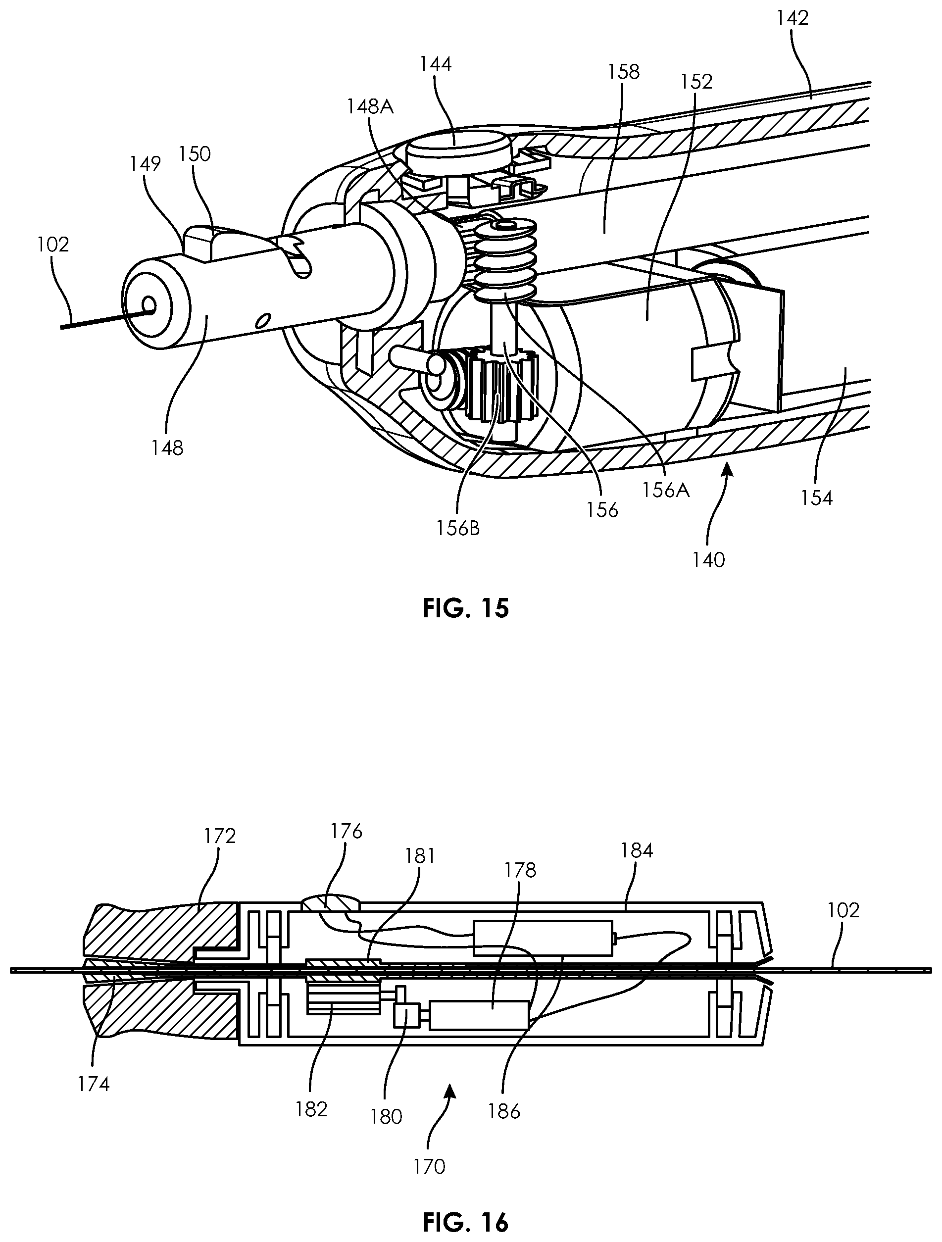
FIG. 15 illustrates a perspective open view of the guidewire manipulation device of FIG. 10.
FIG. 16 illustrates a side open view of a guidewire manipulation device according to an embodiment of the present disclosure.
FIG. 17 illustrates a side open view of the guidewire manipulation device of FIG. 16.
FIG. 18 illustrates a side view of a guidewire manipulation device according to an embodiment of the present disclosure.
FIG. 19 illustrates a side open view of a guidewire manipulation device according to an embodiment of the present disclosure.
FIG. 20 illustrates a side open view of the guidewire manipulation device of FIG. 19.
FIG. 21 illustrates a side open view of a guidewire manipulation device according to an embodiment of the present disclosure.
FIG. 22 illustrates a side open view of the guidewire manipulation device of FIG. 21.
FIG. 23 illustrates a view of one embodiment of a guidewire manipulation device being used on a patient according to an embodiment of the present disclosure.
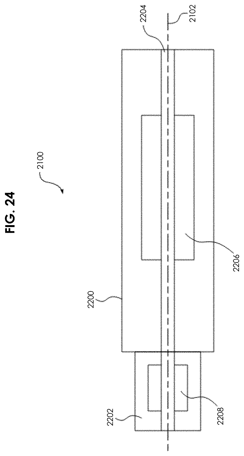
FIG. 24 depicts a schematic block diagram of a guidewire manipulation device according to an embodiment of the present disclosure.
FIG. 25 depicts a vertical cross-sectional view of a guidewire manipulation device according to an embodiment of the present disclosure.
FIG. 26 depicts a portion of an actuator used in the guidewire manipulation device of FIG. 25.
FIG. 27 depicts a perspective view of a hub of a chuck that imparts axial motive force to a guidewire when using the guidewire manipulation divisive FIG. 25.
FIG. 28 depicts a block diagram of a controller for a guidewire manipulation device in accordance with an embodiment of the present disclosure.
FIG. 29 depicts a vertical cross-sectional view of alternative embodiment of the guidewire manipulation device.
FIG. 30 depicts a partial perspective view of a portion of a guidewire drive assembly for the guidewire manipulation device of FIG. 29.
FIG. 31 depicts a cross-sectional view of a portion of the housing for the guidewire manipulation device of FIG. 29.
FIG. 32 depicts a vertical cross-sectional view of the guidewire manipulation device of FIG. 29 having the actuator engaged to apply axial motive force to the guidewire in accordance with one embodiment of the present disclosure.
FIG. 33 depicts a partial, vertical cross-sectional view of another embodiment of a guidewire manipulation device for imparting axial motive force to a guidewire.
FIG. 34 illustrates an aspiration catheter within a blood vessel being used in conjunction with a guidewire which is moved by a guidewire manipulation device, according to an embodiment of the present disclosure.
FIG. 35 illustrates an aspiration catheter within a blood vessel being used in conjunction with a guidewire which is moved by a guidewire manipulation device, according to another embodiment of the present disclosure.
FIG. 36 illustrates an aspiration catheter within a blood vessel used in conjunction with a guidewire which is moved by a guidewire manipulation device, according to another embodiment of the present disclosure.
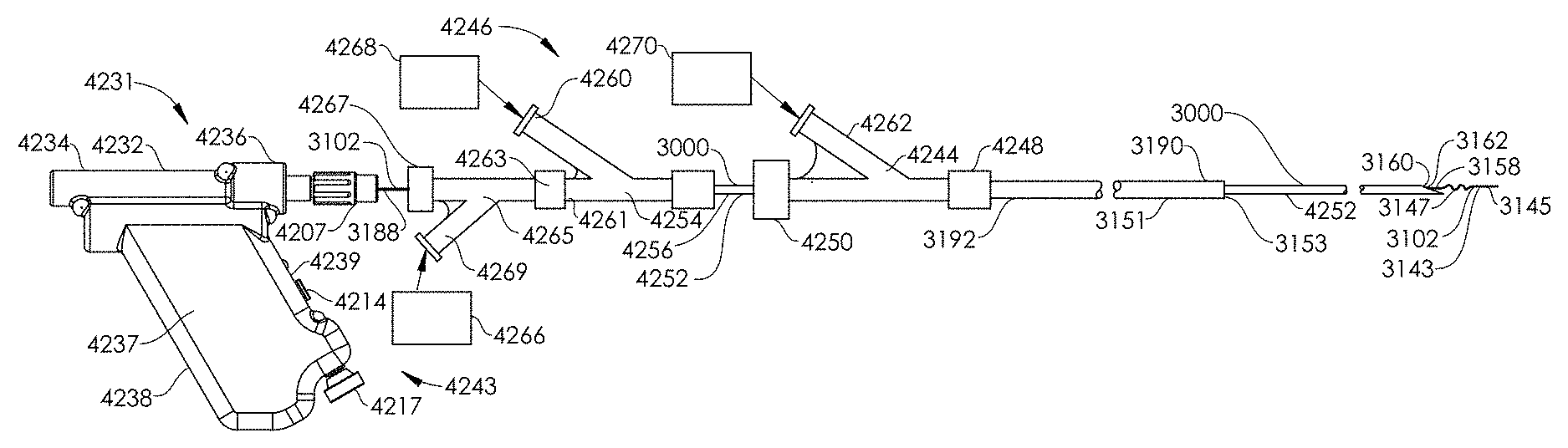
FIG. 37 illustrates a plan view of a system for treating a patient having thrombus, according to an embodiment of the present disclosure.
FIG. 38 illustrates a plan view of a system for treating a patient having thrombus, according to an embodiment of the present disclosure.
DETAILED DESCRIPTION OF THE ILLUSTRATED EMBODIMENTS
Embodiments of the present disclosure comprise systems and methods for manipulating one or more medical devices. The medical devices may include elongated medical devices including, but not limited to: guidewires (guide wires), maceration devices, for example maceration devices having an expending element (such as a basket), cutting devices, atherectomy devices, and a variety of different catheter shafts, including solid catheter shafts and hollow catheter shafts. Conventional guidewire manual manipulation methods often involve applying torque to the guidewire to aid its passage through tortuous, occluded, or stenosed conduits or vessels. The user may sometimes spin the guidewire within the fingers (e.g., gloved fingers) to create a torque which assists in manipulating the guidewire through the challenging anatomy. This technique is sometimes referred to as "helicoptering," alluding to the spinning blades of a helicopter. This technique can be difficult to achieve because the typically small diameter of guidewires makes them difficult to grip. Additionally, it may be difficult to apply necessary friction to the surface of the guidewire to cause them to rotate, because guidewires are often covered with a lubricious coating. For similar reasons, it may be difficult to place a longitudinal force on the guidewires with manual manipulation, including a back-and-forth longitudinal force intended for placing an oscillatory motion on the guidewire.
FIG. 1 illustrates an embodiment of a guidewire manipulation device 100 which is advanced over a guidewire 102. As seen in this figure, the guidewire 102 is introduced into a blood vessel of the patient (e.g., a femoral artery). The manipulation device 100 is slid over the guidewire 102 and selectively locked on to the guidewire 102. As the guidewire 102 is advance into the patient, the user operates the manipulation device 100 to rotate or vibrate the guidewire 102 as appropriate.
For example, as a distal end of the guidewire 102 reaches an angled or curved region of the vessel, the user activates the manipulation device 100 to rotate the guidewire 102 (i.e., in a counter clockwise direction indicated by arrow 103), thereby causing the distal end of the guidewire 102 to more easily advance through the angled or curved region. In another example, the distal end of the guidewire 102 reaches an obstruction (e.g., an embolism) but is unable to easily pass. The user then activates the guidewire manipulation device 100 to vibrate (e.g., by routing between a clockwise and counter clockwise direction quickly), thereby causing the distal end of the guidewire 102 to pass through the obstruction. In another example, the device 100 may include a multiple, preprogrammed rotation patterns appropriate for different vessel configurations (e.g., a 180 degree clockwise rotation followed by 180 degree counter-clockwise rotation, a 90 degree clockwise rotation followed by 90 degree counter clockwise rotation or a 30 degree clockwise rotation followed by 180 degree counter clockwise rotation).
FIGS. 2A and 2B illustrate external views of the guidewire manipulation device 100. The guidewire manipulation device 100 may also include a microprocessor and memory connected to the motor and a button 108 for storing and executing the preprogrammed rotation patterns. As seen in these figures, the guidewire 102 passes through a passage along the length of the guidewire manipulation device 100. Preferably, the guidewire manipulation device 100 includes a locking assembly in the form of a guidewire lock switch 106 which allows the user to selectively lock the guidewire manipulation device 100 to the guidewire 102. In this respect, the guidewire manipulation device 100 can move relative to the guidewire 102 in an unlocked state, and can move the guidewire 102 (rotationally and/or longitudinally) in a locked state.
The guidewire manipulation device 100 also preferably includes a power indicator light 104 (e.g., an LED) which indicates if the device 100 is powered on and a rotation button 108 which causes the guidewire 102 to rotate. By pressing the button 108, the user activates the device 100. Optionally, the device 100 may include a button, switch or similar mechanism to toggle the device 100 between rotating in a clockwise direction or a counter-clockwise direction. Alternately, the button 108 may include multiple actuation techniques for determining clockwise or counter-clockwise rotation (e.g., sliding forward or backward, multiple button presses, etc.).
Preferably, an outer container or casing 110 is composed of a light-weight material such as plastic and has an ergonomic shape that at least partially fits in the user's hand. In this respect, the user can comfortably operate the guidewire manipulation device 100 during a procedure.
Referring to FIGS. 3 and 4, an interior view of the guidewire manipulation device 100 within the outer easing 110 is illustrated according to an embodiment of the present disclosure. The guidewire 102 is engaged by the device 100 with elongated rollers 120 (also seen in the cross sectional view of FIG. 5). Preferably the device 100 includes at least three rollers, however, any number of rollers 120 are possible (e.g., 1-5 rollers). When; the button 108 is pressed, the rollers 120 rotate, thereby rotating the guidewire 102. Preferably, the lock switch 106 raises or lowers one or more of the rollers 120 in relation to the guidewire 102, so as to lock the guidewire 102 with the device 100 when the rollers 120 are pressed against the guidewire 102 and unlock the guidewire 102 from the device 100 when the roller(s) 120 are moved away from the guidewire 102.
One or more of the rollers 120 are preferably driven by a motor 116 which is powered by battery 114 (or alternately by A.C. power such as an outlet). The motor 116 connects to the roller(s) 120 by a cam 119 made up of a first linkage 118 connected to the motor 116 and a second linkage 112 connected to the roller(s) 120. In this respect, activation of the motor 116 drives the cam 119 and ultimately rotation of one or more of the rollers 120.
FIGS. 6 and 7 illustrate another embodiment of a manual manipulation device 130 according to the present disclosure. The device 130 is generally similar to the previously described device 100, except that the rollers 120 and therefore rotation at the guidewire 102 is driven by a handle 126. For example, depressing the handle 126 rotates the guidewire 102 in a clockwise direction (arrow 122) and releasing the handle 126 rotates the guidewire 102 in a counter clockwise direction (arrow 123). Additionally, a switch 124 is included to change a type of rotation caused by the handle 126. For example, the switch 124 may change a gear ratio and therefore the amount of rotation cause by depressing the handle. In another example, the switch 124 may change directions of rotation caused by depressing the handle 126. By manual activation of the handle 126 by the user, the internal drive components drive the rotation of the guidewire 102 without the need of a motor 116.
FIGS. 8 and 9 illustrate another embodiment of a manual guidewire manipulation device 132 which is generally similar to the previously described devices 100 and 130. However, the device 132 includes a selectively locking thumb roller 134 on a distal end of the device 132. The thumb roller 134 includes a locked mode, seen in FIG. 8, in which the roller 134 is engaged with the guidewire 102, thereby allowing the user to roll the roller 134 and thus the guidewire 102. The thumb roller 134 also includes an unlocked mode, seen in FIG. 9, in which the roller 134 is pulled distally from the casing 136, exposing space 138 and disengaging the roller 134 from the guidewire 102. Thus, in the unlocked mode, the device 132 can be moved along the length of the guidewire 102.
FIGS. 10-15 illustrate another embodiment of a guidewire manipulation device 140 according to an embodiment of the present disclosure. The device 140 is generally similar to the previously described device 100. For example, the device 140 includes a hand-held (e.g., configured to be held within a user's hand), ergonomic, outer case 142 and a manipulation button 144. As best seen in FIGS. 11 and 12, the device 140 also includes a motor 152 powered by a battery 154 and a guidewire passage 158 configured for passing the guidewire 102.
Preferably, the device 140 includes a locking assembly in the form of a locking hub 146 (similar to the device 132) which allows the user to selectively lock the guidewire 102 with the device 140. The locking hub 146 allows free movement of the guidewire 102 when positioned near the case 142 (FIG. 11) and locks the guidewire 102 when the hub is pulled away from the case 142 (FIG. 12). The hub 146 includes an interior cavity with a top surface angled downward towards the case 142. Within the interior cavity is a locking wedge 150 which is located within a window 149 of a tube 148 that exposes the guidewire 102. In the unlocked position of FIG. 11, the hub 146 restrains the wedge 150 but does not press down on the wedge 150, thereby allowing the guidewire 102 to slide underneath the wedge 150. In the locked position of FIG. 12, the angled interior surface of the hub 146 forces the wedge downward against the guidewire 102, preventing the guidewire from movement relative to the device 140. A perspective view of the wedge 150 can also be seen in FIG. 15.
As seen in FIGS. 11-15, the motor 152 includes a worm 155 that engages a first gear section 156B of shaft 156. A worm 156A of shaft 158 engages gearing 148A on the outer surface of tube 148. In this respect, when the motor 152 is activated, it ultimately rotates the roller assembly, or tube 148. Thus, the hub 146 must be in a slid-out, locked position to cause the guidewire 102 to rotate.
As with all motorized embodiments described in this specification, the device 140 may also include a microprocessor and memory for storing and executing different rotation sequences (i.e., rotation directions and rotation speeds).
FIGS. 16 and 17 illustrate a guidewire manipulation device 170 according to yet another embodiment according to the present disclosure. The device 170 is generally similar to previously described embodiments, including an outer case 184 having an actuation button 176 that is coupled to a battery 186 and a motor 178. The gear 180 of the motor 178 is engaged with a gear 182 that is also engaged with a geared section 181 on wedge tube 174.
A hub 172 includes an interior, angled passage that increases in diameter in a distal direction. The wedge tube 174 is partially positioned within the hub 172. In the unlocked position of FIG. 16, the angled passage of the hub 172 complements a distally expanding shape of the wedge tube 174, thereby preventing the wedge tube 172 from clamping or providing force on the guidewire 102 and thus allowing the guidewire 102 to slide and rotate relative to the device 170. In the looked position of FIG. 17, the hub 172 is moved distally from the case 184, causing the smaller diameter of the interior passage of the hub 172 to wedge or clamp on to the expanded distal end of the wedge tube 174. Thus, the wedge lobe 174 (preferably composed of a compressible, semi-compressible or deformable material) closes around the guidewire 102, maintaining the position of the guidewire 102 relative to the device 170 and further allowing rotation of the guidewire 102.
FIGS. 18-20 illustrates another embodiment of a device 190 according to the present disclosure. The device 190 is generally similar to the previously described devices. However, the device 190 includes a locking assembly in the form of a guidewire lock activated by depressing a trigger 196. In this respect, the user can rotate hub 192, either clockwise or counter clockwise to respectively rotate the guidewire 102.
The device 190 is generally similar to the previously described embodiments, including a motor 210 powered by a battery 208, a gear 214 coupled to an output gear 212 of the motor 210 and to a geared portion 200B of a wedge tube 200 and a case 194 to contain the components. The motor 210 is controlled by a rocker switch 192 that is connected to a first circuit board 202 which sends the position of the rocker switch 192 to the second circuit board 206. The second circuit board 206 includes a microprocessor and memory for executing a plurality of rotation programs. These rotation programs direct the motor 210 to make predetermined rotation movements such as in a single direction, exponentially increasing rotational speed, quick rotation to cause vibration or a predetermined series of rotational movements. Thus, more complicated movements can be performed by the user.
The device 190 locks on to the guidewire 102 when the user releases trigger 196 (see FIG. 19) and unlocks the guidewire 102 when the user depresses trigger 196. The trigger 196 moves an outer tubing 198 which is biased in a distal direction by a spring 204. The interior passage of the outer tubing 198 increases in diameter in a distal direction forming an inverted cone shape. An inner wedge tube 200 is positioned within the passage of the outer tubing 198 and includes a wedge 200A that increases in size in a distal direction of the device 190. The guidewire 102 is located within a passage of the wedge tube 200.
When the trigger 196 is released, as in FIG. 19, the outer tubing 198 is moved distally by the spring 204, causing the smaller diameter region of the inner passage of the outer tubing 198 to press against the wedge 200A of wedge tube 200. The wedge 200 then compresses around the guidewire 102, locking the guidewire 102 in place relative to the device 190. When the trigger 196 is depressed, as in FIG. 20, a portion of the trigger 196 pushes the outer tubing 198 in a proximal direction, against the bias of the spring 204. The angled portions of the inner passage of the outer tubing 198 move away from the wedge 200a, allowing the inner passage of the wedge tube 200 to release the guidewire 102. Thus, the user can selectively lock on to and rotate the guidewire 102 (with the roller assembly, including wedge tube 200) by releasing the trigger 196 and pressing the actuation button 192.
FIGS. 21 and 22 illustrate another embodiment of a guidewire manipulation device 220 according to the present disclosure. The device 220 is generally similar to the previously described embodiments. Including a battery 234 powering a motor 236 which drives a wedge tube 224 (via a gear 240 connected to geared region 224B and output gear 238) and an actuation button 228.
The device 220 further includes a locking mechanism assembly that locks the lateral position of the guidewire 102. As seen in FIG. 21, when the user releases the trigger 232, the device remains in a locked position, allowing the user to rotate the guidewire 102. As seen in FIG. 22, when the user depresses the trigger 232, the device remains in an unlocked position, allowing the user to slide the device 220 along the guidewire 102 and preventing guidewire rotation.
In the locked position, the trigger 232 maintains an outer tube 222 in a proximal position, proximally biased by a spring 226. The outer tube includes an inner passage that generally decreases in diameter in a distal direction. The inner surface of the outer tube 222 presses against a wedge portion 224A of a wedge tube 224, causing the wedge tube 224 to press against and lock onto the guidewire 102.
In the unlocked position, the trigger 232 pushes the outer tube 222 distally, against the bias of the spring 226. The surface of the inner passage of the outer tube 222 moves away from the wedge 224A, releasing the wedge tube 224 from the guidewire 102.
The systems and methods disclosed herein further comprise a guidewire manipulation device for selectively imparting motive force (rotational and/or axial/longitudinal (linear) motion) to a guidewire. In use, such a guidewire manipulation device is selectively locked to a guidewire and is activated to impart motive force to maneuver the guidewire to a desired location during an endovascular procedure. The motive force applied to the guidewire is selectively rotational or axial to facilitate moving the guidewire through a vessel and/or penetrating occlusions.
FIG. 23 illustrates a view of a guidewire manipulation device 2100 being used on a patient 2110 according to one embodiment of the present disclosure. In one embodiment, the guidewire manipulation device 2100 is a handheld device capable of fitting in the palm of a user's hand and being operated using one hand. In one embodiment, the guidewire manipulation device 2100 is advanced over a guidewire 2102, i.e., the guidewire 2102 passes through a longitudinally oriented passage in the device 2100. During an endovascular procedure, the guidewire 2102 is introduced into a vessel 2106 (e.g., a femoral artery) of the patient 2110. The guidewire manipulation device 2100 is selectively locked to the guidewire 2102. As the guidewire is advanced into the patient, the user operates the manipulation device 2100 to impart motive force (rotational and/or axial motion) to the guidewire 2102, as appropriate.
For example, as a distal end 2108 of the guidewire 2102 reaches an angled, curved, stenosed, or occluded region of the vessel 2106, the user locks the manipulation device 2100 to the guidewire and imparts rotational motive force to the guidewire 2102 (e.g., in a counter-clockwise direction indicated by arrow 2104), thereby causing the distal end 2108 of the guidewire 2102 to more easily advance through the angled, curved, stenosed, or occluded region of the vessel 2106. Once advanced past the region, the device 2100 is unlocked from the guidewire and the guidewire can be further advanced through the vessel. In another example, the distal end 2108 of the guidewire 2102 reaches an obstruction (e.g., an embolism, including, but not limited to a thromboembolism) but is unable to pass the obstruction. The user then locks the guidewire manipulation device 2100 to the guidewire 2102 and imparts a vibratory motion (e.g., rapidly oscillating between clockwise and counter-clockwise rotation). Such motion causes the distal end 2108 of the guidewire 2102 to pass through the obstruction. In another example, when the distal end 2108 of the guidewire 2102 reaches an obstruction, the user locks the guidewire manipulation device 2100 to the guidewire 2102 and imparts an axial motion (e.g., a linear movement of the guidewire 2102) to create a jackhammer effect. In another embodiment, the user may lock the device 2100 to the guidewire 2102 and simultaneously impart both rotational and axial motion to the guidewire 2102. In another embodiment of the present disclosure, a sequence of predefined guidewire manipulations (i.e., a pattern) may be produced using a computer program for controlling the motion as described in detail below. Various motive patterns to be selectively used in various surgical situations can be selected from memory and applied to the guidewire.
FIG. 24 depicts a schematic block diagram of one embodiment of a guidewire manipulation device 2100. The guidewire manipulation device 2100 defines an axially longitudinal passage 2204 through which the guidewire 2102 is threaded during use. The guidewire manipulation device 2100 comprises a housing 2200, an actuator 2206, and a chuck 2202. The chuck 2202 comprises a guidewire locking mechanism 2208. During use, the chuck 2202 is locked to the guidewire 2102 using the looking mechanism 2208. Once locked, the actuator selectively imparts motive force (rotational motion and/or axial motion) to the guidewire 2102.
FIG. 25 depicts a vertical cross-sectional view of one embodiment of a guidewire manipulation device 2100. In this embodiment, the actuator 2206 of FIG. 24 is divided into a rotary actuator 2206A and an axial actuator 2206B such that the device may selectively apply to the guidewire: no motive force, rotary motive force or rotary and axial motive force.
Device 2100 comprises a housing 2200 typically formed into halves that are glued, bonded, screwed, or otherwise affixed to each other to form an enclosure. Within the housing 2200 are defined slots 350 wherein are retained bushings 302A and 302B. The bushings 302A and 302B support an axle 300 on its outer surface 310. The axle 300 defines the passage 2204 extending axially through the axle 300. When in use, the guidewire 2102 is threaded through the passage 2204.
The rotary actuator 2206A comprises the axle 300, a motor 328, a drive assembly 326, a controller 330, and a control switch 332. The drive assembly 326 couples rotational motion of the motor 328 to the axle 300 using a plurality of gears, further described with respect to FIG. 26 below. In one embodiment of the present disclosure, the controller 330 is simply one or more batteries that are coupled to the motor 328 via the control switch 332. In such an embodiment, the control switch 332 may simply apply a voltage from the one or more batteries to the motor 328 to cause the motor 328 to rotate. In its simplest form, the control switch 332 is a simple single-pole, single-throw (SPST), momentary contact switch. In other embodiments, the controller 330 comprises a programmable microcontroller as described with respect to FIG. 28 below. In other embodiments, the switch 332 may apply voltage to cause the motor 328 to selectively rotate clockwise or counter-clockwise. The control switch 332 is generally mounted to be exposed to the exterior of the housing 2200 and facilitate manipulation by one hand of a user (e.g., a thumb activated push-button or slide switch.
The axle 300 is coupled to a chuck 2202. In one embodiment, the chuck 2202 comprises a coupler 304, a hub 324 and a wedge 314. The coupler 304 and the axle 300 have splined mating surfaces 342 for coupling the rotational motion of the axle 300 to the chuck 2202, while allowing the coupler 304 to move in an axial direction. The hub 324 is threaded onto the coupler 304 at surface 312. The wedge 314 is located in a window 352 defined by the coupler 304. The hub 324 retains the wedge 314 within the window 352. In a disengaged (unlocked) position, the hub 324 does not impart pressure to the wedge 314 thereby allowing the guidewire 2102 to slide freely beneath the wedge 314 and through the passage 2204. To lock (engage) the guidewire into the lock mechanism 2208, the hub 324 is rotated relative to the coupler 304 such that the angled surface 316 of the hub 324 interacts with the top surface 308 of the wedge 314. As the hub 324 is moved relative to the coupler 304 via the mating threaded surfaces 312, the wedge 314 is forced against the guidewire 2102. Consequently, the guidewire 2102 is captured between the wedge 314 and the coupler 304 and thereby locked into the chuck 2202. Once locked, any motion of the chuck 2202 (e.g., rotational and/or longitudinal) is imparted as motive force to the guidewire 2102.
Other embodiments of the present disclosure utilize other forms of chucks. In a broad sense, any mechanism that can be used to selectively lock the guidewire to a source of motive force may be used. Other forms of chucks having multiple jaws or compressive slotted cylinders are applicable.
The coupler 304 comprises a spring seat 354 supporting a first end of a spring 306. The second end of spring 306 rests against a flange 322 that extends from the inner surface of the housing 2200. The spring 306 is one embodiment of a resilient member that biases the coupler 304 inwardly toward the axle 300. The coupler 304 further comprises a flange 320 that extends radially from the outer surface of the coupler 304. The flange 320 is positioned along the coupler 304 to limit the amount of axial movement that can be imparted to the chuck 2202. The flange 320 abuts the housing flange 322. As such, the spring 306 biases the coupler 304 to maintain contact between the flange 320 and the flange 322.
To impart axial (longitudinal) motion to the chuck 2202, the bottom surface 356 of the hub 324 is dimpled. The surface 356 interacts with a protrusion 336 extending from the exterior surface of the housing 2200 proximate the surface 356 of the hub 324. Depending on the position of the hub 324 relative to the coupler 304, the spring 306 insures that the protrusion 336 interacts with the dimpled surface 356. Upon locking the chuck 2202 to the guidewire 2102 and imparting rotation to the chuck 2202, the guidewire 2102 moves in an axial direction as indicated by arrow 358. To disengage the axial motive force, the hub 324 is rotated relative to the coupler 304 along the threads 312 to decouple the protrusion 336 from the surface 356. In this manner, the locking mechanism 2208 retains the guidewire 2102 such that rotational motion of the axle 300 is imparted to the guidewire 2102 without imparting axial motion. In this embodiment, the axial motion actuator 2206B comprises the hub 324, spring 306, coupler 304 and the housing 2200.
FIG. 26 depicts a cross sectional view of the drive assembly 326 of the rotary actuator 2206A taken along line 26-26 of FIG. 25 in accordance with one embodiment of the present disclosure. The drive assembly 326 comprises a motor gear 400, an intermediary gear 402 and an axle gear 404. The motor 328 of FIG. 25 is coupled to the motor gear 400 to impart rotational motion to the motor gear 400. In one embodiment, the axle gear 404 is formed as an integral part of this surface of the axle 300 of FIG. 25. The intermediary gear 402 is designed to provide a gear ratio between the motor gear 400 and axle gear 404. The diameters and the number of teeth of each gear is considered to be a design choice that will define the speed of rotational motion of the guidewire 2102 as well as the oscillatory speed of the axial motion.
In other embodiments, the motor 328 of FIG. 25 may be coupled to the axle via other forms of drive assemblies, e.g., direct drive, worm gear, and/or the like. The specific motor and drive assembly characteristics are considered a design choice to develop specific guidewire rotation speed and torque. In some embodiments, the drive assembly may be adjustable to facilitate creating specific speed and torque profiles or adjustments. One form of adjustments may be facilitated by the use of a stepper motor that can be controlled with a pulse width modulated signal produced by the controller, as discussed below.
An alternative embodiment for imparting rotary motive force in selectable directions uses a gear train comprising two larger diameter spur gears mounted on a common shaft that is driven constantly in one direction by an electric motor. Each of the two spur gears has a section of its teeth, something over 1/
D00000
D00001
D00002
D00003
D00004
D00005
D00006
D00007
D00008
D00009
D00010
D00011
D00012

D00013

D00014
D00015

D00016

D00017

D00018

D00019

D00020

D00021

D00022

D00023

XML
uspto.report is an independent third-party trademark research tool that is not affiliated, endorsed, or sponsored by the United States Patent and Trademark Office (USPTO) or any other governmental organization. The information provided by uspto.report is based on publicly available data at the time of writing and is intended for informational purposes only.
While we strive to provide accurate and up-to-date information, we do not guarantee the accuracy, completeness, reliability, or suitability of the information displayed on this site. The use of this site is at your own risk. Any reliance you place on such information is therefore strictly at your own risk.
All official trademark data, including owner information, should be verified by visiting the official USPTO website at www.uspto.gov. This site is not intended to replace professional legal advice and should not be used as a substitute for consulting with a legal professional who is knowledgeable about trademark law.