Aesthetic method of biological structure treatment by magnetic field
Schwarz , et al. Fe
U.S. patent number 10,549,109 [Application Number 15/860,443] was granted by the patent office on 2020-02-04 for aesthetic method of biological structure treatment by magnetic field. This patent grant is currently assigned to BTL Medical Technologies S.R.O.. The grantee listed for this patent is BTL Medical Technologies S.R.O.. Invention is credited to Ondra Prouza, Toma{hacek over (s)} Schwarz.


View All Diagrams
| United States Patent | 10,549,109 |
| Schwarz , et al. | February 4, 2020 |
Aesthetic method of biological structure treatment by magnetic field
Abstract
Methods for treating a patient using a time varying magnetic field are described. The treatment methods combine various approaches for aesthetic treatment. The methods are focused on enhancing a visual appearance of the patient. An exemplary method includes charging an energy storage device and discharging the energy storage device to a magnetic field generating device to generate the time-varying magnetic field. The time-varying magnetic field is applied to the patient.
| Inventors: | Schwarz; Toma{hacek over (s)} (Prague, CZ), Prouza; Ondra ({hacek over (R)}i{hacek over (c)}any u Prahy, CZ) | ||||||||||
|---|---|---|---|---|---|---|---|---|---|---|---|
| Applicant: |
|
||||||||||
| Assignee: | BTL Medical Technologies S.R.O.
(Prague, CZ) |
||||||||||
| Family ID: | 67057887 | ||||||||||
| Appl. No.: | 15/860,443 | ||||||||||
| Filed: | January 2, 2018 |
Prior Publication Data
| Document Identifier | Publication Date | |
|---|---|---|
| US 20190201706 A1 | Jul 4, 2019 | |
Related U.S. Patent Documents
| Application Number | Filing Date | Patent Number | Issue Date | ||
|---|---|---|---|---|---|
| 15677371 | May 22, 2018 | 9974519 | |||
| 15446951 | Apr 10, 2018 | 9937358 | |||
| 15396073 | Dec 30, 2016 | ||||
| 15178455 | Jun 9, 2016 | ||||
| 15151012 | Nov 13, 2018 | 10124187 | |||
| 15099274 | Apr 14, 2016 | ||||
| 15073318 | Mar 20, 2018 | 9919161 | |||
| 14951093 | Nov 24, 2015 | ||||
| 14926365 | Oct 29, 2015 | ||||
| 14789658 | May 2, 2017 | 9636519 | |||
| 14789156 | Jul 1, 2015 | ||||
| 15860443 | |||||
| 15473390 | Mar 29, 2017 | ||||
| 15404384 | Jan 12, 2017 | ||||
| 62440905 | Dec 30, 2016 | ||||
| 62440912 | Dec 30, 2016 | ||||
| 62440922 | Dec 30, 2016 | ||||
| 62440936 | Dec 30, 2016 | ||||
| 62440940 | Dec 30, 2016 | ||||
| 62441805 | Jan 3, 2017 | ||||
| Current U.S. Class: | 1/1 |
| Current CPC Class: | A61N 5/0625 (20130101); A61B 90/50 (20160201); A61N 5/0622 (20130101); A61N 2/002 (20130101); A61N 1/06 (20130101); A61N 2/02 (20130101); A61B 18/203 (20130101); A61F 7/00 (20130101); A61N 2/004 (20130101); A61N 5/0624 (20130101); A61N 5/0613 (20130101); A61N 7/00 (20130101); A61N 1/40 (20130101); A61N 5/062 (20130101); A61N 2005/0659 (20130101); A61N 5/0616 (20130101); A61B 2018/00005 (20130101); A61B 2018/00464 (20130101); A61N 2/008 (20130101); A61N 2007/0008 (20130101); A61N 2007/0034 (20130101); A61N 2005/0661 (20130101); A61B 2017/00154 (20130101); A61N 2005/005 (20130101); A61B 2018/00559 (20130101); A61F 2007/004 (20130101); A61N 2005/0662 (20130101); A61B 18/22 (20130101); A61B 2017/00106 (20130101); A61B 2018/0047 (20130101); A61F 2007/0022 (20130101); A61F 2007/0041 (20130101); A61N 2005/0663 (20130101); A61B 2018/00452 (20130101); A61N 2005/0626 (20130101); A61N 2005/066 (20130101); A61N 2005/067 (20130101); A61N 2005/0644 (20130101); A61B 2018/00791 (20130101) |
| Current International Class: | A61N 2/00 (20060101); A61N 2/02 (20060101) |
| Field of Search: | ;600/9-15 |
References Cited [Referenced By]
U.S. Patent Documents
| 3658051 | April 1972 | MacLean |
| 3915151 | October 1975 | Kraus |
| 4237898 | December 1980 | Whalley |
| 4315503 | February 1982 | Ryaby et al. |
| 4454883 | June 1984 | Fellus |
| 4456001 | June 1984 | Pescatore |
| 4665898 | May 1987 | Costa et al. |
| 4674505 | June 1987 | Pauli et al. |
| 4850959 | July 1989 | Findl |
| 4993413 | February 1991 | McLeod et al. |
| 5067940 | November 1991 | Liboff et al. |
| 5085626 | February 1992 | Frey |
| 5099459 | March 1992 | Smith |
| 5401233 | March 1995 | Erickson et al. |
| 5718662 | February 1998 | Jalinous |
| 5766124 | June 1998 | Polson |
| 5782743 | July 1998 | Russell |
| 5807232 | September 1998 | Espinoza et al. |
| 5984854 | November 1999 | Ishikawa et al. |
| 6063108 | May 2000 | Salansky et al. |
| 6086525 | July 2000 | Davey et al. |
| 6117066 | September 2000 | Abrams et al. |
| 6179769 | January 2001 | Ishikawa et al. |
| 6179770 | January 2001 | Mould |
| 6213933 | April 2001 | Lin |
| 6223750 | May 2001 | Ishikawa et al. |
| 6402678 | June 2002 | Fischell et al. |
| 6418345 | July 2002 | Tepper et al. |
| 6527694 | March 2003 | Ishikawa et al. |
| 6569078 | May 2003 | Ishikawa et al. |
| 6939287 | September 2005 | Ardizzone et al. |
| 7030764 | April 2006 | Smith et al. |
| 7520849 | April 2009 | Simon |
| 7601115 | October 2009 | Riehl |
| 7608035 | October 2009 | Farone |
| 7740574 | June 2010 | Pilla et al. |
| 7744523 | June 2010 | Epstein |
| 7946973 | May 2011 | Peterchev |
| 7998053 | August 2011 | Aho |
| 8088058 | January 2012 | Juliana et al. |
| 8979727 | March 2015 | Ron et al. |
| 9002477 | April 2015 | Burnett |
| 9586057 | March 2017 | Ladman et al. |
| 9636519 | May 2017 | Ladman et al. |
| 9919161 | March 2018 | Schwarz et al. |
| 9937358 | April 2018 | Schwarz et al. |
| 10124187 | November 2018 | Schwarz et al. |
| 10245439 | April 2019 | Schwarz et al. |
| 2001/0031906 | October 2001 | Ishikawa et al. |
| 2003/0158585 | August 2003 | Burnett |
| 2006/0152301 | July 2006 | Rohwedder |
| 2006/0187607 | August 2006 | Mo |
| 2006/0287566 | December 2006 | Zangen et al. |
| 2007/0083237 | April 2007 | Teruel |
| 2008/0249350 | October 2008 | Marchitto et al. |
| 2008/0262287 | October 2008 | Dussau |
| 2008/0306325 | December 2008 | Burnett et al. |
| 2008/0306326 | December 2008 | Epstein |
| 2009/0005631 | January 2009 | Simenhaus et al. |
| 2009/0018384 | January 2009 | Boyden et al. |
| 2009/0108969 | April 2009 | Sims et al. |
| 2010/0036368 | February 2010 | England et al. |
| 2010/0081971 | April 2010 | Allison |
| 2010/0087699 | April 2010 | Peterchev |
| 2010/0121131 | May 2010 | Mathes |
| 2010/0152522 | June 2010 | Roth et al. |
| 2010/0160712 | June 2010 | Burnett et al. |
| 2010/0179372 | July 2010 | Glassman |
| 2010/0222629 | September 2010 | Burnett et al. |
| 2010/0309689 | December 2010 | Coulson |
| 2010/0331603 | December 2010 | Szecsi |
| 2011/0021863 | January 2011 | Burnett et al. |
| 2011/0077451 | March 2011 | Marchitto et al. |
| 2011/0130618 | June 2011 | Ron et al. |
| 2011/0263925 | October 2011 | Bratton |
| 2012/0053449 | March 2012 | Moses et al. |
| 2012/0302821 | November 2012 | Burnett |
| 2012/0310033 | December 2012 | Muntermann |
| 2013/0030239 | January 2013 | Weyh et al. |
| 2013/0053620 | February 2013 | Susedik et al. |
| 2013/0123568 | May 2013 | Hamilton et al. |
| 2013/0123764 | May 2013 | Zarsky et al. |
| 2013/0123765 | May 2013 | Zarsky et al. |
| 2013/0137918 | May 2013 | Phillips et al. |
| 2013/0150653 | June 2013 | Borsody |
| 2013/0158634 | June 2013 | Ron Edoute et al. |
| 2013/0238061 | September 2013 | Ron Edoute et al. |
| 2013/0317281 | November 2013 | Schneider et al. |
| 2013/0331637 | December 2013 | Greff |
| 2014/0046423 | February 2014 | Rajguru et al. |
| 2014/0148870 | May 2014 | Burnett |
| 2014/0330067 | November 2014 | Jordan |
| 2014/0371515 | December 2014 | John |
| 2015/0025299 | January 2015 | Ron Edoute et al. |
| 2015/0123661 | May 2015 | Yui et al. |
| 2015/0133717 | May 2015 | Ghiron |
| 2015/0157873 | June 2015 | Sokolowski |
| 2015/0216719 | August 2015 | DeBenedictis et al. |
| 2015/0328475 | November 2015 | Kim et al. |
| 2015/0367141 | December 2015 | Goetz et al. |
| 2016/0030763 | February 2016 | Midorikawa et al. |
| 2016/0051827 | February 2016 | Ron Edoute et al. |
| 2016/0250494 | September 2016 | Sakaki et al. |
| 2017/0001024 | January 2017 | Prouza |
| 2017/0001025 | January 2017 | Schwarz et al. |
| 2017/0001029 | January 2017 | Pribula et al. |
| 2017/0001030 | January 2017 | Pribula et al. |
| 2017/0072212 | March 2017 | Ladman et al. |
| 2017/0106201 | April 2017 | Schwarz et al. |
| 2017/0120067 | May 2017 | Prouza |
| 2018/0001106 | January 2018 | Schwarz |
| 2018/0125416 | May 2018 | Schwarz et al. |
| 2018/0236254 | August 2018 | Schwarz et al. |
| 201906360 | Jul 2011 | CN | |||
| 1118902 | Dec 1961 | DE | |||
| 3205048 | Aug 1983 | DE | |||
| 3610474 | Oct 1986 | DE | |||
| 0209246 | Jan 1987 | EP | |||
| D459401 | Dec 1991 | EP | |||
| 2676700 | Dec 2013 | EP | |||
| 2017518857 | Jul 2017 | JP | |||
| 2002025675 | Mar 2002 | WO | |||
| 2003090863 | Nov 2003 | WO | |||
| 03/103769 | Dec 2003 | WO | |||
| 2004087255 | Oct 2004 | WO | |||
| 2008109058 | Sep 2008 | WO | |||
| 2010007614 | Jan 2010 | WO | |||
| 2010135425 | Nov 2010 | WO | |||
| 2015012672 | Jan 2015 | WO | |||
| WO-2015179571 | Nov 2015 | WO | |||
Other References
|
Lin, et al., "Functional Magnetic Stimulation: A New Modality for Enhancing Systemic Fibrinolysis," Arch Phys Med Rehabil vol. 80, May 1999, pp. 545-550. cited by applicant . Polk, "Therapeutic Applications of Low-Frequency Sinusoidal and Pulsed Electric and Magnetic Fields," The Biomedical Engineering Handbook, vol. 1, 2000, Second edition, pp. 1625-1636. cited by applicant . European Patent Office, International Search Report and Written Opinion for International Application No. PCT/IB2016/053930; dated Dec. 12, 2016; 19 pages. cited by applicant . Abulhasan, J.F., et al., "Peripheral Electrical and Magnetic Stimulation to Augment Resistance Training," Journal of Functional Morphology and Kinesiology, 1(3):328-342, (Sep. 2016). cited by applicant . Bachasson, D., et al., "Quadriceps Function Assessment Using an Incremental Test and Magnetic Neurostimulation: a Reliability Study," Journal of Electromyography and Kinesiology, 23(3):649-658, Elsevier, England, (Jun. 2013). cited by applicant . Barker, A.T, "An Introduction to the Basic Principles of Magnetic Nerve Stimulation," Journal of Clinical Neurophysiology, 8(1):26-37, Lippincott Williams & Wilkins, United States, (Jan. 1991). cited by applicant . Behrens, M., et al., "Repetitive Peripheral Magnetic Stimulation (15 Hz RPMS) of the Human Soleus Muscle did not Affect Spinal Excitability," Journal of Sports Science and Medicine, 10(1):39-44, Dept. of Sports Medicine, Medical Faculty of Uludag University, Turkey (Mar. 2011). cited by applicant . Beilin, G., et al., "Electromagnetic Fields Applied to the Reduction of Abdominal Obesity," Journal of Cosmetic & Laser Therapy, 14(1):24-42, Informa Healthcare, England, (Feb. 2012). cited by applicant . Bustamante, V., et al., "Muscle Training With Repetitive Magnetic Stimulation of the Quadriceps in Severe COPD Patients," Respiratory Medicine, 104(2):237-245, Elsevier, England, (Feb. 2010). cited by applicant . Bustamante, V., et al., "Redox Balance Following Magnetic Stimulation Training in the Quadriceps of Patients With Severe COPD," Free Radical Research, 42(11-12):939-948, Informa Healthcare, England, (Nov. 2008). cited by applicant . Caress, J.B., et al., "A Novel Method of Inducing Muscle Cramps Using Repetitive Magnetic Stimulation," Muscle Nerve, 23(1):126-128, John Wiley & Sons, United States, (Jan. 2000). cited by applicant . Course in Physical Therapy, Presentation, Jan. 4, 2013, 156 pages. cited by applicant . CR Technology, Salus-Talent, Technical File of Electro-magnetic Stimulator, Document No. TF-C05, 2008, 241 pages. cited by applicant . CR Technology, Technology for Health and Business for Human Being, investor relations, 2008, 21 pages. cited by applicant . Effective PEMF Magnetic Fat Reduction Slimming Body Beauty Salon Machine (PEMF Star), Wolfbeauty 1980, PEMF Star, China, Retrieved from the Internet: (URL: https://www.ec21.com/product-details/Effective-PEMF-Magnetic-Fat-Reductio- n--8928746.html), 2019, 5 pages. cited by applicant . Goetz, S.M., et al., "Coil Design for Neuromuscular Magnetic Stimulation Based on a Detailed 3-D Thigh Model," IEEE Transactions on Magnetics, 50(6):10, IEEE, (Jun. 2014). cited by applicant . Gorodnichev, R.M., "Magnetic Stimulation of Muscles as New Method to Enhance Their Strength," Velikie Luki State Academy of Physical Culture and Sport, Velikie Luki, 2016, 5 pages. cited by applicant . Operating Manual: Magstim Magstim 200.sup.2, MOP01-EN, Revision 01, The Magstim Company Limited, Sep. 2011, 25 Pages. cited by applicant . Operating Manual: Magstim, Magstim Alpha Coil Range, MOP11-EN, Revision 01, Oct. 2012, 18 Pages. cited by applicant . Operating Manual: Magstim, Magstim Bistim.sup.2, MOP02-EN, Revision, The Magstim Company Limited, Sep. 1, 2011, 27 Pages. cited by applicant . Operating Manual, MAGSTIM, Model 200, P/N 3001-01, Double 70mm, Remote Coil, P/N 3190-00, The Magstim Company Limited, 2006, 32 pages. cited by applicant . Operating Manual: Magstim R, 2nd, Generation Coil Family, 3100-23-02, Magstim Coils, The Magstim Company Limited, Nov. 2002, 14 Pages. cited by applicant . Operating Manual, MAGSTIM R Air-Cooled Double 70mm Coil System, 1600-23-04, The Magstim Company Limited, 1999, 18 Pages. cited by applicant . Operating Manual: MAGSTIM R, BISTIM System, P/N 3234-23-01, The Magstim Company Limited, Nov. 2004, 30 Pages. cited by applicant . Operating Manual: Magstim R, Coils & Accessories, 1623-23-07, Magstim Coils & Accessories, May 2010, 24 Pages. cited by applicant . Operating Manual: MAGSTIM, RAPID2, P/N 3576-23-09, The MAGSTIM Company Ltd, Nov. 2009, 61 Pages. cited by applicant . Operator's Manual: BTL Emsculpt, BTL Industries Ltd, United Kingdom, 2018, 35 pages. cited by applicant . Operator's Manual: BTL, HPM-6000U, BTL Industries Ltd, United Kingdom, Dec. 2016, 36 pages. cited by applicant . Papimi, for Scientific Research, Pap Ion Magnetic Inductor, Presentation, Magnetotherapeutic Device, Nov. 2009, 61 Pages. cited by applicant . Podebradsky.K., et al., Clinical study of high-inductive electromagnetic stimulator SALUS talent, 2010, 8 pages. cited by applicant . Polkey M.I., et al., "Functional Magnetic Stimulation of the Abdominal Muscles in Humans," American Journal of Respiratory and Critical Care Medicine, 160(2):513-522, American Thoracic Society, United States (Aug. 1999). cited by applicant . Polkey, M.I., et al., "Quadriceps Strength and Fatigue Assessed by Magnetic Stimulation of the Femoral Nerve in Man," Muscle Nerve, 19(5):549-555, John Wiley & Sons, United States, (May 1996). cited by applicant . Quick Start Manuals, Magstim Super Rapid Plus Quick Start, Aalto TMS Laboratory, Aalto School of Science, 2013, 7 Pages. cited by applicant . Hamnegard, C.H., et al., "Quadriceps Strength Assessed by Magnetic Stimulation of the Femoral Nerve in Normal Subjects," Clinical Physiology and Functional Imaging, 24(5):276-280, Blackwell, England, (Sep. 2004). cited by applicant . Han, T.R., et al., "Magnetic Stimulation of the Quadriceps Femoris Muscle: Comparison of Pain With Electrical Stimulation," American Journal of Physical Medicine & Rehabilitation, 85(7):593-599, Lippincott Williams & Wilkins, United States, (Jul. 2006). cited by applicant . Increasing Physiotherapy Presence in Cosmetology, Spa Inspirations, Jan. 2012, pp. 34-35. cited by applicant . Iskra Medical, Magneto System, 2012, 2 pages. cited by applicant . Katuscakova, Z.L., et al., High Induction Magnet Therapy in Rehabilitation, Department of Physiactric Rehabilitation, 2012, 72 pages. cited by applicant . Lampropoulou, S.I., et al., "Magnetic Versus Electrical Stimulation in the Interpolation Twitch Technique of Elbow Flexors," Journal of Sports Science and Medicine, 11(4):709-718, Dept. of Sports Medicine, Medical Faculty of Uludag University, Turkey (Dec. 2012). cited by applicant . Lin, V.W., et al., "Functional Magnetic Stimulation for Restoring Cough in Patients With Tetraplegia," Archives of Physical Medicine and Rehabilitation, 79(5):517-522, W.B. Saunders, United States, (May 1998). cited by applicant . Lin, V.W., et al., "Functional Magnetic Stimulation of Expiratory Muscles: a Noninvasive and New Method for Restoring Cough," Journal of Applied Physiology (1985), 84(4)1144-1150, American Physiological Society, United States, (Apr. 1998). cited by applicant . Madariaga, V.B., et al., "[Magnetic Stimulation of the Quadriceps: Analysis of 2 Stimulators Used for Diagnostic and Therapeutic Applications]," Archivos de Bronconeumologia, 43(7):411-417, Elsevier Espana, Spain, (Jul. 2007). cited by applicant . Mag Venture, Magnetic Stimulation, Accessories Catalogue, Accessories Catalogue, 2011, 54 pages. cited by applicant . MagVenture, MagPro.RTM. by MagVenturee.RTM., Versatility in Magnetic Stimulation, World Leading Transcranial Magnetic Stimulation Systems, 2011, 6 Pages. cited by applicant . Neuro Star, TMS Therapy, Bringing Hope to Patients with Depression, 2013, 6 Pages. cited by applicant . Neurosoft, Ivanovo, Since 1992, Magnetic Stimulator, NEURO-MS, Technical Manual, Neurosoft Ltd, Ivanovo, Russia, 2006, 67 Pages. cited by applicant . Nexstim NBS System, Navigated Brain Stimulation, Noninvasive, direct cortical mapping, 2012, 5 Pages. cited by applicant . Obsluze, N.K., Usage Instructions, User's Manual, Device for high-induction magnetic stimulation of type designation:Saluter Moti, 2016, 88 Pages. cited by applicant . Operating Manual: Magstim D70.sup.2 Coil, MOP06-EN, Revision 01, The Magstim Company Limited, Feb. 2012, 14 Pages. cited by applicant . Salus Talent-A, REMED, User Guide, High Intensity Electro Magnetic Field Therapy, 2017, 37 pages. cited by applicant . DuoMAG Magnetic Stimulator, Alien Technik User Manuel, Jun. 26, 2012, 48 pages, Version 2.1. cited by applicant . Szecsi, J., et al., "A Comparison of Functional Electrical and Magnetic Stimulation for Propelled Cycling of Paretic Patients," Archives of Physical Medicine and Rehabilitation, 90(4):564-570, W.B. Saunders, United States, (Apr. 2009). cited by applicant . Szecsi, J., et al., "Force-pain Relationship in Functional Magnetic and Electrical Stimulation of Subjects With Paresis and Preserved Sensation," Clinical Neurophysiology, 121(9):1589-1597, Elsevier, Netherlands, (Sep. 2010). cited by applicant . Taylor, J.L, "Magnetic Muscle Stimulation Produces Fatigue Without Effort," Journal of Applied Physiology (1985), 103(3):733-734, American Physiological Society, United States, (Sep. 2007). cited by applicant . Tesla Stym, Iskra Medical, Tone the inner muscle with FMS Functional Magnetic Stimulation, 2013, 4 pages. cited by applicant . User Guide: Mag Venture, Magpro family, MagPro R30, MagPro R30 with MagOption, MagPro X100, MagPro X100 with MagOption, MagPro software v.5.0, US-edition, MagPro family User Guide, 2010, 52 Pages. cited by applicant . User Guide, Salus Talent Pro, REMED, High Intensity Electro magnetic Field Therapy-2 Channel, 2017, Version M-1.0.0, 45 pages. cited by applicant . User Guide, Salus Talent, REMED, High Intensity Electro magnetic Field Therapy, Version. M-1.0.0, 2017, 40 pages. cited by applicant . User's Manual: BTL-6000, Super Inductive System Elite, BBTL Industries Ltd, United Kingdom, Sep. 2016, 36 pages. cited by applicant . User Manual: Electro-magnetic Stimulator, Salus-Talent, Version 1.00, Rehabilitation Medical Company, 2013, 34 Pages. cited by applicant . User Manual: Regenetron PRO, System Information, Regenetron PRO User Manual, Nov. 2014, 7 Pages. cited by applicant . Verges S., et al., "Comparison of Electrical and Magnetic Stimulations to Assess Quadriceps Muscle Function," Journal of Applied Physiology (1985), 106(2):701-710, American Physiological Society, United States, (Feb. 2009). cited by applicant . Wasilewski, M.L., Academy of Aesthetic and Anti-Aging Medicine, Application of magnetic fields with deep stimulation in the fight against local obesity of lower limbs, BTL, 2012, 4 pages. cited by applicant. |
Primary Examiner: Gilbert; Samuel G
Attorney, Agent or Firm: Sterne, Kessler, Goldstein & Fox P.L.L.C.
Parent Case Text
PRIORITY CLAIM
This application is a Continuation-in-Part of U.S. patent application Ser. No. 15/677,371, filed Aug. 15, 2017, now issued as U.S. Pat. No. 9,974,519; which is a Continuation-in-Part of U.S. patent application Ser. No. 15/446,951, filed Mar. 1, 2017 and now issued as U.S. Pat. No. 9,937,358; which is a Continuation-in-Part of U.S. patent application Ser. No. 15/396,073, filed Dec. 30, 2016 and now abandoned; which is a Continuation-in-Part of U.S. patent application Ser. No. 15/178,455, filed Jun. 9, 2016 and now abandoned; which is a Continuation-in-Part of U.S. patent application Ser. No. 15/151,012, filed May 10, 2016 and now issued as U.S. Pat. No. 10,124,187; which is a Continuation-in-Part of U.S. patent application Ser. No. 15/099,274, filed Apr. 14, 2016 and now abandoned; which is a Continuation-in-Part of U.S. patent application Ser. No. 15/073,318, filed Mar. 17, 2016 and now issued as U.S. Pat. No. 9,919,161; which is a Continuation-in-Part of U.S. patent application Ser. No. 14/951,093, filed Nov. 24, 2015 and now abandoned; which is a Continuation-in-Part of U.S. patent application Ser. No. 14/926,365, filed Oct. 29, 2015 and now abandoned; which is a Continuation-in-Part of U.S. patent application Ser. No. 14/789,156, filed Jul. 1, 2015 and now pending; and which is a Continuation-in-Part of U.S. patent application Ser. No. 14/789,658, filed Jul. 1, 2015 and now U.S. Pat. No. 9,636,519.
This application is a Continuation-In-Part of Ser. No. 15/601,719, filed May 22, 2017, now pending.
This application is a Continuation-In-Part of Ser. No. 15/473,390, filed Mar. 29, 2017, now abandoned.
This application is a Continuation-In-Part of U.S. patent application Ser. No. 15/404,384, filed Jan. 12, 2017, now pending.
This application claims the benefit of and priority to U.S. Provisional Patent Application Nos. 62/440,905, filed Dec. 30, 2016; 62/440,912, filed Dec. 30, 2016; 62/440,922, filed Dec. 30, 2016; 62/440,936, filed Dec. 30, 2016; 62/440,940, filed Dec. 30, 2016; and 62/441,805, filed Jan. 3, 2017. Each of these applications listed above is incorporated herein by reference.
Claims
The invention claimed is:
1. A method for shaping a muscle of a patient using a treatment device including an energy storage device, and an applicator housing a magnetic field generating device, the method comprising: attaching the applicator by a belt to the patient; charging the energy storage device, the energy storage device having a capacitance in a range between 5 nF and 100 mF and the energy source having a voltage of at least 100 V; and discharging the energy storage device to the magnetic field generating device; generating, by the magnetic field generative device, pulses of a first time-varying magnetic field, pulses of a second time-varying magnetic field, and pulses of a third time-varying magnetic field, each of the pulses of the first, second, and third time-varying magnetic fields comprising a magnetic flux density in a range between 0.4 T and 7 T, and an impulse duration in a range of 3 .mu.s and 3000 .mu.s; assembling the pulses of the first time-varying magnetic field with a first repetition rate in a range of 1 Hz to 15 Hz into a first train of pulses; assembling the pulses of the second time-varying magnetic field with a second repetition rate between 15 Hz and 45 Hz into a second train of pulses; assembling the pulses of the third time-varying magnetic field into a third train of pulses; and applying the first, the second, and the third trains of pulses to muscle fibers, neuromuscular plates, or peripheral nerves innervating the muscle fibers within a body region of the patient such that the muscle is caused to contract, wherein the step of applying the second train of pulses follows the step of applying the first train of pulses, and wherein a relaxation period follows each of the first, second, and third trains of pulses.
2. The method of claim 1, wherein steps of assembling the first and second trains of pulses further comprises: modulating pulses of the first or second time-varying magnetic fields into a trapezoidal envelope shape.
3. The method of claim 1 wherein the relaxation period lasts in a range of 1 second to 30 seconds.
4. The method of claim 1, wherein the body region includes at least one of a buttock, a thigh, a hip, an abdomen, or an arm, a torso, or flanks of the patient.
5. The method of claim 1, further comprising: applying shock waves with a positive peak pressure in a range between 0.1 MPa and 150 MPa to the body region of the patient.
6. The method of claim 1, further comprising: applying ultrasound waves with a frequency in a range between 100 kHz and 100 MHz to the body region of the patient.
7. The method of claim 1, wherein the applicator is connected to the treatment device by a connecting tube, the connecting tube includes a conduit for receiving fluid.
8. The method of claim 1, wherein the applicator further includes a casing having a marker to determine a position of the magnetic field generating device within the applicator.
9. The method of claim 1, wherein the third train of pulses has a third repetition rate in a range between 25 Hz and 75 Hz.
10. The method of claim 9, further comprising: applying pulses of a fourth time-varying magnetic field to the muscle fibers, neuromuscular plates, or peripheral nerves innervating muscle fibers within the body region of the patient such that the muscle is caused to contract, wherein the pulses of the fourth time-varying magnetic field include a fourth repetition rate in a range of 2 Hz to 90 Hz.
11. A method for shaping a muscle of a patient using a treatment device including an energy storage device and a magnetic field generating device, the method comprising: charging the energy storage device; discharging the energy storage device with a current pulse to the magnetic field generating device; generating, by the magnetic field generating device, a first time-varying magnetic field including a first train of pulses, a second time-varying magnetic field including a second train of pulses, and a third time-varying magnetic field including a third train of pulses, each of the first, second, and third time-varying magnetic fields comprises an impulse duration in a range between 3 .mu.s and to 1000 .mu.s, wherein the first train of pulses includes a first repetition rate in a range of 1 Hz to 100 Hz, wherein the second train of pulses includes a second repetition rate in a range of 10 Hz to 30 Hz, and herein the third train of pulses includes a third repetition rate in a range of 30 Hz to 60 Hz; applying the first train of pulses, the second train of pulses, and the third train of pulses to muscle fibers, neuromuscular plates, or peripheral nerves innervating muscle fibers within a body region of the patient such that the muscle is caused to contract; and applying no time-varying magnetic field for a period of time after the first train of pulses and the second train of pulses such that the muscle is caused to relax, wherein the step of applying the third train of pulses follows the step of applying the second train of pulses.
12. The method of claim 11, wherein the treatment device further comprises an applicator housing the magnetic field generating device, and wherein the applicator is configured to be secured to the patient by a belt.
13. The method of claim 12, wherein the applicator is concave shaped.
14. The method of claim 11, further comprising: applying optical waves with a power flux density in a range of 0.1 W/cm2 to 100 W/cm2 to the body region of the patient.
15. The method of claim 11, wherein the treatment device further includes a first magnetic field generating circuit and a second magnetic field generating circuit, and wherein the magnetic field generating device includes a first magnetic field generating device housing the first magnetic field generating circuit and a second field generating device housing the second magnetic field generating circuit.
16. The method of claim 15, further comprising: adjusting an orientation of the first and second magnetic field generating devices such that the first and second magnetic field generating devices are mutually tilted relative to a plane.
17. The method of claim 11, further comprising: applying a fourth train of pulses with a fourth repetition rate in a range between 2 Hz and 90 Hz to the to the muscle fibers, neuromuscular plates, or peripheral nerves innervating muscle fibers within a body region of a patient such that the muscle is caused to contract.
18. The method of claim 11, wherein the energy source having a voltage of at least 500 V.
19. The method of claim 11, further comprising: applying radiofrequency waves with a frequency range between 500 kHz and 3 GHz to the body region of the patient.
20. A method for treating a patient using a treatment device including an energy storage device, a magnetic field generating device, and an applicator, the method comprising: placing the applicator housing the magnetic field generating device in contact with the patient's skin or clothing; charging the energy storage device; discharging the energy storage device to the magnetic field generating device; generating, by the magnetic field generating device, a first time-varying magnetic field having a first train of magnetic pulses with a repetition rate in a range of 1 Hz to 300 Hz; generating, by the magnetic field generating device, a second time-varying magnetic field having a second train of magnetic pulses with a second repetition rate in a range of 10 Hz to 45 Hz; generating, by the magnetic field generating device, a third time-varying magnetic field having a third train of magnetic pulses with a repetition rate different than the first repetition rate and the second repetition rate; cooling the magnetic field generating device; applying a first burst including the first train of magnetic pulses, a second burst including the second train of magnetic pulses, and a third burst including the third train of magnetic pulses to muscle fibers, neuromuscular plates, or peripheral nerves innervating muscle fibers within a body region of the patient such that a muscle is caused to contract; and applying no time-varying magnetic field for a period of time after the first train and the second train such that the muscle is caused to relax.
21. The method of claim 20, wherein the first burst differs from the second burst by at least one parameter selected from a group consisting of a number of pulses, a train duration, a repetition rate, and a magnetic flux.
22. The method of claim 20 wherein the applicator is connected to the treatment device by a connecting tube, the connecting tube includes a conduit for receiving fluid.
23. The method of claim 20, wherein the magnetic field generating device further comprises a first magnetic field generating device and a second magnetic field generating device, wherein the applicator further comprises a first applicator housing the first magnetic field generating device and a second applicator housing the second magnetic field generating device, and wherein each of the first and second magnetic field generating devices generate the first time-varying magnetic field including the first train of magnetic pulses, the second time-varying magnetic field including the second train of magnetic pulses, and the third time-varying magnetic field including the third train of magnetic pulses.
24. The method of claim 23, wherein each of the steps of applying the first and second time-varying magnetic fields comprises a treatment duty cycle in a range between 10% and 80%.
25. The method of claim 23, wherein the first train of magnetic pulses generated by the first and second magnetic field generating devices are applied simultaneously, wherein the second train of magnetic pulses generated by the first and second magnetic field generating devices are applied simultaneously, and wherein the third train of magnetic pulses generated by the first and second magnetic field generating devices are applied simultaneously.
26. A method for treating a patient using a treatment device including an energy storage device, a magnetic field generating device, and an applicator, the method comprising: attaching the applicator housing the magnetic field generating device by a belt to the patient; charging the energy storage device; and discharging the energy storage device to the magnetic field generating device; generating, by the magnetic field generating device, a time-varying magnetic field including a plurality of magnetic pulses; cooling the magnetic field generating device; and assembling the plurality of magnetic pulses into a first train of pulses having a first repetition rate and a first duration lasting between 1 second and 30 seconds; assembling the plurality of magnetic pulses into a second train of pulses having a second repetition rate and a second duration lasting between 1 second and 30 seconds; assembling the plurality of magnetic pulses into a third train of pulses having a third repetition rate; and applying the first train of pulses, the second train of pulses, and the third train of pulses to muscle fibers, neuromuscular plates, or peripheral nerves innervating muscle fibers within a body region of the patient such that a muscle is caused to contract; wherein the first train of pulses is applied in a first burst, and the first burst includes a first period of no magnetic treatment, wherein the second train of pulses is applied in a second burst, and the second burst includes a second period of no magnetic treatment, wherein the first repetition rate, the second repetition rate and the third repetition rate are set at different rates, and wherein the body region includes at least one of a buttock, a thigh, a hip, an abdomen, or an arm of the patient.
27. The method of claim 26 wherein the applicator includes a marker disposed above a center of the magnetic field generating device.
28. The method of claim 26, wherein the second repetition rate is greater than the first repetition rate, and wherein the third repetition rate is less than the first repetition rate.
29. The method of claim 26 wherein the treatment device further includes a voltage sensor configured to measure voltage values of the energy storage device, wherein the treatment device is configured to determine a maximal value of at least one of the magnetic flux density, the repetition rate, and the impulse duration of the first time-varying magnetic field based on the measured voltage and indicate the maximal value to an operator.
30. The method of claim 26 wherein the treatment device further includes a first magnetic field generating circuit and a second magnetic field generating circuit, wherein the magnetic field generating device includes a first magnetic field generating device housing the first magnetic field generating circuit and a second field generating device housing the second magnetic field generating circuit.
Description
FIELD OF THE INVENTION
The present invention generally relates to methods using the influence of magnetic and induced electric field on biological structure. The magnetic field is time-varying and high powered therefore the method is based on a value of magnetic flux density sufficient to induce at least partial muscle contraction.
LIST OF REFERENCE NUMBERS
1 magnetic field generating device 2 circuit wire 3 fastening point 4 blower 5 applicator 6 arrow 7 casing 8 outlet 9 connecting tube 10 fluid conduit 11 treatment device 12 positioning arm 13 applicator 14 wheels 15 moveable link 16 joint 17 one end of positioning arm 18 sleeve 19 second end of positioning arm 20 gap 21 guiding member 22 latching member 23 switch 24 magnetic field generating device 25 energy storage device 26 energy source 27 protection circuitry 28 magnetic field generating device 29 energy storage device 30 switch 31 energy source 32 adipose cell 33 lipolysis 34 ER stress 35 apoptosis of adipose cell 36 Ca2+ release 37 patient 38 treatment device 39 magnetic field generating device 40 pressure generating device 41 magnetic treatment device 42 pressure device 43 patient 44 treatment device 45 magnetic field generating device 46 heating/cooling means 47 magnetic treatment device 48 heating/cooling device 49 handle 50 concavity 51 marker 52 magnetic field generating circuit 53 power supply 54 switching device 55 energy storage device 56 magnetic field generating device 57 magnetic field generating circuit 58 power supply 59 switching device 60 energy 61 magnetic field generating device
BACKGROUND OF THE INVENTION
Aesthetic medicine includes all treatments resulting in enhancing a visual appearance and satisfaction of the patient. Patients want to minimize all imperfections including body shape and effects of natural aging. Indeed, patients request quick, non-invasive procedures providing satisfactory results with minimal risks.
The most common methods used for non-invasive aesthetic applications are based on application of mechanical waves, e.g. ultrasound or shock wave therapy; or electromagnetic waves, e.g. radiofrequency treatment or light treatment, such as intense pulsed light or laser treatment. The effect of mechanical waves on tissue is based especially on cavitation, vibration and/or heat inducing effects. The effect of applications using electromagnetic waves is based especially on heat production in the biological structure. However the currently used treatment methods are used separately.
A mechanical treatment using mechanical waves and/or pressure were used for treatment of cellulite or adipose cells. However, mechanical treatment includes several drawbacks such as risk of a panniculitis and/or non-homogenous result.
A thermal treatment is applied to the patient for enhancing a visual appearance of the skin by e.g. increasing production of collagen and/or elastin, smoothing the skin or reduction of cellulite and/or adipose cell. However, thermal treatment includes several drawbacks such as risk of overheating a patient or even causing a thermal damage to the patient, risk of a panniculitis and/or non-homogenous result.
The mechanical and/or the thermal treatment is not able to provide enhanced visual appearance of a muscle, e.g. muscle shaping, toning and/or volumization effect. Mechanical treatment and/or the thermal treatment includes several drawbacks such as risk of a panniculitis, non-homogenous result and others.
Current magnetic methods are limited in key parameters which do not allow satisfactory enhancement of visual appearance. As a result, new methods are needed to enhance the visual appearance of the patient.
Existing devices have low efficiency and they waste energy, which limits their use. Eddy currents induced within the magnetic field generating device create engineering challenges. Existing devices contain magnetic field generating devices which are made of metallic strips, electric wires or hollow conductors. Since the therapy requires large currents, significant losses are caused by induced eddy currents within the magnetic field generating device. Eddy currents lead to production of unwanted heat and therefore there is need to sufficiently cool the magnetic field generating device. Also, the energy source must be protected during reverse polarity of resonance. This requires using protective circuits which consume significant amounts of energy. Skin tissue is composed of three basic elements: epidermis, dermis and hypodermis or so called subcutis. The outer and also the thinnest layer of skin is the epidermis. The dermis consists of collagen, elastic tissue and reticular fibers. The hypodermis is the lowest layer of the skin and contains hair follicle roots, lymphatic vessels, collagen tissue, nerves and also fat forming a subcutaneous white adipose tissue (SWAT). The adipose cells create lobules which are bounded by connective tissue, fibrous septa (retinaculum cutis).
Another part of adipose tissue, so called visceral fat, is located in the peritoneal cavity and forms visceral white adipose tissue (VWAT) located between parietal peritoneum and visceral peritoneum, closely below muscle fibers adjoining the hypodermis layer.
The currently used aesthetic applications don't provide any treatment combining the effect of time-varying magnetic field treatment and conventional treatment method, e.g. treatment by thermal treatment and/or mechanical treatment. The currently used thermal treatment includes many adverse events such as non-homogenous temperature distribution, panniculitis, insufficient blood and/or lymph flow during and/or after the treatment. Additionally several adverse event such as panniculitis may occur after the treatment. Further the treatment may be painful so that a topical anesthetic is recommended.
The development of new aesthetic treatment methods providing improved results in shorter time periods is needed.
SUMMARY OF THE INVENTION
The present methods and devices as described below produce a time varying magnetic field for patient treatment which better optimizes energy use, increases the effectiveness of the treatments and provide a new treatment. The magnetic pulses may be generated in monophasic, biphasic or polyphasic regimes. In a first aspect, the device has one or more magnetic field generating devices; a switch; an energy storage device and a connection to an energy source. The magnetic field generating device may be made of insulated wires wherein a conductor diameter is less than 10 mm, preferably less than 3 mm, even more preferably less than 0.5 mm and the most preferably less than 0.05 mm. Smaller diameter and individual insulation of the wires significantly reduces self-heating of the magnetic field generating device and therefore increase efficiency of magnetic stimulation device. The magnetic field generating device may be flexibly attached in a casing of device. The casing may comprise a blower or blowers which ensure cooling of the magnetic field generating device.
The present methods provide new aesthetic applications for focused remodeling of the patient's body. The magnetic field generating device of the magnetic stimulation device may be flexibly attached to casing of the device. The blower or blowers may be arranged to blow air on both sides of magnetic field generating device. Optionally, the magnetic field generating device may be a flat type magnetic field generating device.
The new magnetic treatment methods may improve a muscle of the patient. Further the new magnetic treatment method enables improved treatment results. Alternatively the magnetic treatment may provide pain relief and/or myorelaxation effect to the patient.
The method of treating a biological structure uses a combination of non-invasive methods for enhancing human appearance. The invention utilizes electromagnetic field. Methods may be used for targeted remodeling of adipose tissue, focused treatment of cellulite, body contouring, skin tightening or skin rejuvenation. The invention relates to focused heating of the target tissue by electromagnetic waves, whereas the effect of focused heating of the target tissue is amplified by the effect of a magnetic treatment.
The magnetic treatment induces the muscle contraction at higher repetition rates and the contraction is stronger. Therefore the treatment is more efficient for reducing the number and/or volume of adipocytes and enhancing the visual appearance of the treated body region via targeted muscle contraction. Further the temperature homogeneity of is improved. Additionally, strong muscle contractions at higher repetition rates cause mechanical movement of all the layers in proximity of the contracted muscle. The methods therefore cause remodeling and/or neogenesis of the collagen and elastin fibers.
The methods enable new treatments by magnetic and/or electromagnetic field. The repetition rate of the magnetic field is in the range of 1 to 300 Hz with high magnetic flux density up to 7 Tesla (equivalent to 70000 Gauss). The frequency of the electromagnetic field is 13.56 or 40.68 or 27.12 MHz or 2.45 GHz.
On the other hand, a combination with a magnetic treatment method may enhance the visual appearance of the muscle and/or other soft tissue such as skin or adipose tissue.
The methods enable combined treatment using different treatment methods such as magnetic and/or conventional treatment methods. The combination of different treatment methods provide a complex treatment method for focused treatment of a treated body region.
The present methods provide combined treatment using influence of magnetic treatment and mechanical treatment by shock waves, ultrasound waves, acoustic waves and/or pressure application. The mechanical treatment may induce mechanical damage to the treated biological structure and/or tissues. Ultrasound waves may heat adipose cells, dermis, hypodermis or other target biological structure. Ultrasound waves may also induce a cavitation.
The present method provides combined treatment using magnetic treatment and thermal treatment. Heating/cooling may cause an apoptosis and/or necrosis of the target biological structure such as adipose cells. Remodeling of the target biological structure is more significant and treatment duration is reduced. Potential risks for the patient associated with single treatment methods are avoided. Further the side effects such as swelling and/or inflammation are reduced and/or eliminated.
GLOSSARY
Conventional non-invasive and/or invasive aesthetic treatment methods refer to aesthetic applications based on application of mechanical waves, e.g. acoustic wave, ultrasound or shock wave therapy; or electromagnetic waves, e.g. radiofrequency or diathermy treatment or light treatment, such as intense pulsed light or laser treatment; or mechanical stimulation, e.g. positive or negative pressure, rollerball, massage etc.; or thermal treatment, e.g. cryotherapy; or electrotherapy method; or mesotherapy method and or any combination thereof.
Thermal treatment refers to treatment by heating or cooling, e.g. a cryotherapy treatment.
Mechanical treatment refers to treatment methods using applying a pressure such as positive or negative; applying mechanical waves such as shock waves, ultrasound waves or vibration.
Biological structure is at least one neuron, neuromuscular plate, muscle fiber, adipose cell or tissue, collagen, elastin, pigment or skin.
Remodeling target biological structure refers to reducing the number and/or volume of the adipocytes by apoptosis and/or necrosis, cellulite treatment, body shaping and/or contouring, muscle toning, skin tightening, collagen treatment, skin rejuvenation, wrinkle removing, reducing stretchmarks, breast lifting, lip enhancement, treatment of vascular or pigmented lesions of the skin or hair removing.
Body region includes muscle or muscle group, buttocks, saddlebags, love handles, abdomen, hips, thighs, arms, limb and/or any other tissue.
Muscle includes at least one of muscle fiber, muscle tissue or group, neuromuscular plate or nerve innervating the at least one muscle fiber.
Deep muscle refers to a muscle that is at least partly below superficial muscles and/or to the muscle that is covered by the thick layer of other tissue, e.g. mostly adipose tissue and/or the skin, with thickness 0.5, 1, 2, 3, 4, 5 or more centimeters.
Adipose tissue refers to at least one lipid rich cell, e.g. adipocyte.
Bolus refers to a layer of fluid material, e.g. water or fluid solution of ceramic particles, preferably enclosed in a flexible sac made of biocompatible material.
Impulse refers to a single magnetic stimulus.
Pulse refers to a period of treatment by a magnetic field of at least one magnetic stimulus and time duration of no stimulation, i.e. time duration between two impulses from rise/fall edge to next rise/fall edge.
Repetition rate refers to frequency of firing the pulses; it is derived from the time duration of a pulse.
Combined treatment refers to a combination of at least two different treatment methods, e.g. application of magnetic field and thermal treatment, application of magnetic field and mechanical treatment, or application of magnetic field with thermal treatment and mechanical treatment.
BRIEF DESCRIPTION OF THE DRAWINGS
FIGS. 1A and 1B are cross section views of a magnetic field generating device winding.
FIG. 2 is a cross-section of a magnetic applicator.
FIG. 3A-C illustrate exemplary embodiment of an applicator.
FIG. 4A-4C illustrates a positioning arm
FIGS. 5A and 5B illustrate circuits for providing high power pulses to a stimulating magnetic field generating device.
FIG. 6 is a diagram of areas.
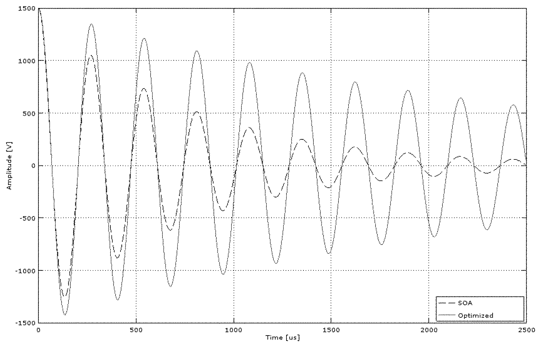
FIG. 7 is a graph showing voltage drop in the energy storage device.
FIG. 8 illustrates an exemplary treatment duty cycle
FIG. 9 is a diagram of a biological effect.
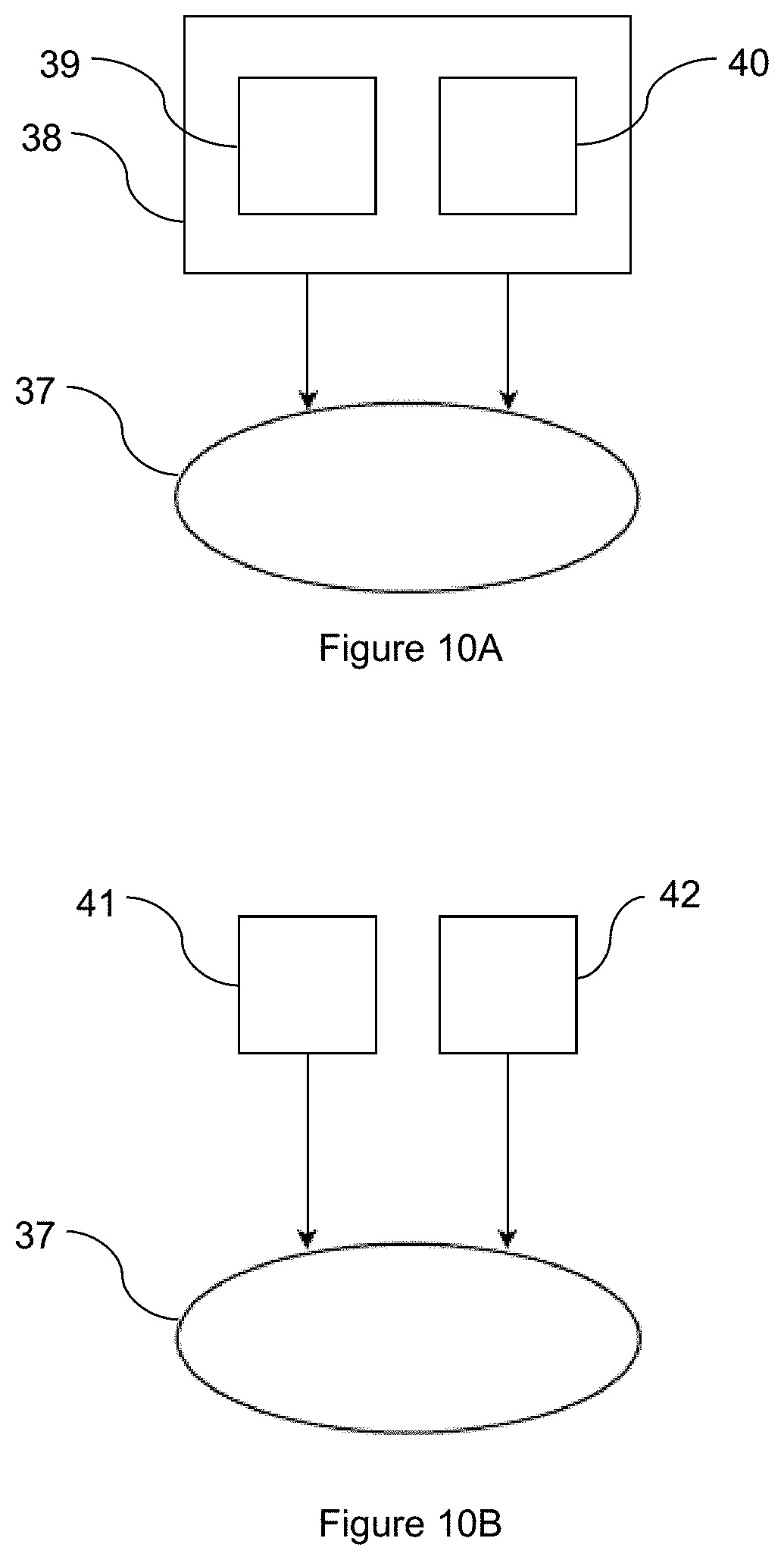
FIGS. 10A and 10B illustrate diagrams of a treatment device and/or an applicator providing magnetic and/or mechanical treatment.
FIGS. 11A and 11B illustrate diagrams of a treatment device and/or an applicator providing magnetic and/or thermal treatment.
FIG. 12 illustrates an exemplary embodiment of a treatment device including two circuits generating independent magnetic fields.
FIG. 13 illustrates an exemplary trapezoidal envelope.
FIG. 14 illustrates types of muscle contraction.
FIGS. 15A-15D illustrate exemplary applications for buttock treatment.
FIG. 16 illustrates an exemplary application for abdomen treatment.
DETAILED DESCRIPTION
The magnetic treatment device may include at least one magnetic field generating device. Alternatively the magnetic treatment device may include a plurality of the magnetic field generating devices. The at least one applicator may include at least one magnetic field generating device. Alternatively at least one applicator may include the plurality of the magnetic field generating devices.
FIG. 1 illustrates a cross section of winding of a magnetic field generating device for a magnetic stimulation device. The magnetic field generating device may be constructed from litz-wire, wherein each wire is insulated separately. Each individual conductor is coated with non-conductive material so the magnetic field generating device constitutes multiple insulated wires. Unlike existing magnetic field generating device conductors, the present magnetic field generating device is not made of bare wire e.g. litz-wire without insulation, or conductive tapes, conductive strips, or copper pipe with hollow inductors. The insulation of wires separately is a substantial improvement, since this leads to a significant reduction of the induced eddy currents. Power loss due to eddy currents, per single wire, is described by Equation 1 below. The small diameter of wires significantly reduces self-heating of the magnetic field generating device and therefore increases efficiency of the present magnetic stimulation device.
.pi..rho..times. ##EQU00001##
where: P.sub.EDDY is power loss per unit mass (Wkg.sup.-1); B.sub.p is the peak of magnetic field (T); f is frequency (Hz); d is the thickness of the sheet or diameter of the wire (m); k is constant equal to 1 for a thin sheet and 2 for a thin wire; .rho. is the resistivity of material (.OMEGA.m); D is the density of material (kgm.sup.3).
The individual insulation of each wire reduces eddy currents. The individually insulated wires may be wound either one by one or in a bundle of individually insulated wires so as to form a magnetic field generating device, which will serve as a magnetic field generator. The magnetic field generating device provides an improvement in the efficiency of energy transfer in the LC resonant circuit and also reduces or eliminates unwanted thermal effects.
The magnetic field generating device may have a planar magnetic field generating device shape where the individually insulated wires may have cross-section wires with conductor diameter less than 20, 10, 5, 3, 1, 0.5 or 0.05 mm. The wires are preferably made of materials with higher density and higher resistivity e.g. gold, platinum or copper. The diameters of the single wires should be minimal. On the other hand the total diameter should be maximal because of inverse proportion between the cross-section of all wires forming the magnetic field generating device and the electrical resistance. Therefore the ohmic part of the heat is then lower. Eq. 2 describes power loss of the magnetic field generating device:
.rho..times. ##EQU00002##
Where: P.sub.R is the power loss heat dissipation (W); .rho. is the resistance (.OMEGA.m); l is the length of wire (m); S is the surface area (m.sup.2); I is the current (A) and m is 1 kg of wire material.
Total power loss is (Eq. 3): P.sub.TOT=P.sub.EDDY+P.sub.R, Eq. 3
Where: P.sub.TOT is the total power losses (Wkg.sup.-1); P.sub.EDDY is the power dissipation of eddy currents (Wkg.sup.-1); P.sub.R is the power loss heat dissipation (Wkg.sup.-1).
Dynamic forces produced by current pulses passing through the wires of the magnetic field generating device cause vibrations and unwanted noise. The individual insulated wires of the magnetic field generating device may be impregnated under pressure so as to eliminate air bubbles between the individual insulated wires. The space between wires can be filled with suitable material which causes unification, preservation and electric insulation of the system. Suitable rigid impregnation materials like resin, and elastic materials like PTE can be also used. With the magnetic field generating device provided as a solid mass, the vibrations and resonance caused by movements of the individual insulated wires are suppressed. Therefore noise is reduced.
The magnetic field generating device may be attached to the case of the applicator, such as a hand held applicator of the magnetic stimulation device; build-in applicator in e.g. chair, bed; or stand-alone applicator e.g. on mechanical fixture. The hand held applicator may include a display unit for controlling the magnetic treatment device. Alternatively the display unit may display treatment parameters such as a repetition rate, a magnetic flux density or lapsed time of the treatment.
The mechanical fixture may be rigid with the applicator hanging on the rigid mechanical fixture. Alternatively the mechanical fixture may be articulated. The mechanical fixture may include at least one joint to enable tailor made position of the applicator. The attachment may be provided by an elastic material e.g., silicone, gum; or other flexible manner. Connection with the magnetic field generating device of the applicator's casing may be ensured by several points. The several fastening points ensure the connection of the magnetic field generating device to the casing by flexible material so that the main part of the magnetic field generating device and the main part of the casing of applicator are spaced apart. The spacing should be at least 0.1 mm so that air can easily flow. Alternatively the spacing may be at least 1 mm, most preferably at least 5 mm to enable cooling media flow. The gap between the magnetic field generating device and the casing can be used either for spontaneous or controlled cooling. The magnetic field generating device may optionally be connected to the case of the applicator by only one fastening point. The fastening points eliminate vibrations of wires which could be transferred to housing of the applicator and therefore reduce noise of the magnetic stimulation device.
FIG. 2 is a cross-section of the magnetic applicator which allows better flow on the lower and upper sides of the magnetic field generating device and thus more efficient heat dissipation. The magnetic stimulation device includes a magnetic field generating device 1, the circuit wires 2 and the fastening points 3 for connection of the magnetic field generating device to the casing of the applicator (not shown). The fastening points 3 are preferably made of flexible material however the rigid material may be used as well. The fastening points 3 may be located on the outer circumferential side of the magnetic field generating device. However, alternatively it is possible to put these fastening points to a lower or upper side of the magnetic field generating device.
The fastening points 3 connect the magnetic field generating device to the case of the applicator in at least one point. The fastening points 3 maintain the magnetic field generating device and the main part of the case of the applicator spaced apart so that fluid (which may be air or any liquid) can flow between them. At least one blower 4 can be placed around the circumference of the magnetic field generating device, or perpendicular to the magnetic field generating device. The blower can be any known kind of device for directing the fluid e.g. outer air directed into the case of the applicator. The blower may be e.g. a fan or a vacuum pump. This arrangement of the blower allows air to bypass the magnetic field generating device from upper and lower (patient's) sides. In still another embodiment the outer air can be cooled before directing into the case. The blower can have an inlet placed around the circumference of the magnetic field generating device for injecting air, to remove heat from the magnetic field generating device. A connecting tube (not shown) can ensure connection of the applicator 5 with the energy source and/or control unit of magnetic stimulation device. The connecting tube may also contain a conduit of the fluid, e.g. a pressurized air.
Alternatively the magnetic field generating device may be attached to the casing of the applicator via a circular rigid member encircling the magnetic field generating device. The outer circumference of the circular rigid member may be attached to the casing of the applicator. The magnetic field generating device may be flexibly attached to the inner circumference of the circular rigid member by at least one attaching point. Alternatively the magnetic field generating device may be attached to the circular member by its entire circumference.
The arrows 6 indicate the air flow through the applicator 5. This arrangement of the blower allows the air to bypass the magnetic field generating device from upper and lower (patient's) side. Outlet may be preferably placed on upper side of the casing. The outlet may include a plurality of holes enabling unimpeded removing of heated cooling media from the casing of the applicator. By placing the blower around the circumference of the magnetic field generating device instead of on the top/below the magnetic field generating device, the blower 4 does not interfere with the magnetic flux peak and therefore its lifespan and reliability is increased.
FIG. 3A is an illustrative embodiment of a casing of the magnetic applicator. The overview drawing contains casing itself 7, which might contain an outlet 8 preferably placed on upper side of the casing 7. The applicator may further include a handle 49 on the upper side of the casing. The handle 47 may be used for manual positioning the applicator. A connecting tube 9 may not only ensure connection of the applicator with the energy source and/or control unit of magnetic stimulation device, but also connection to a source of the fluid; however the conduit of the fluid 10 may also be connected separately.
In an alternative embodiment cooling may be provided by a member using thermoelectric effect, e.g. a Peltier cooler. Alternatively, cooling may be provided by Stirling engine cooling system.
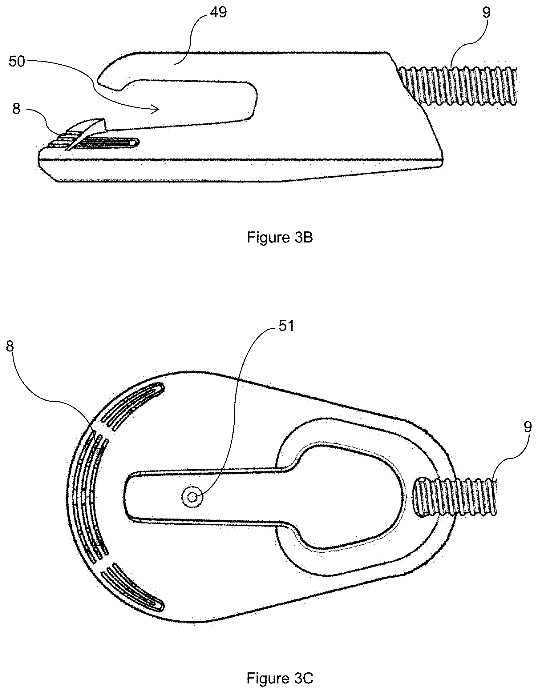
FIG. 3B illustrates a side view of an exemplary embodiment of concave applicator. The applicator of concave shape includes a handling member 49 as a concavity 50 of the applicator. The concavity may enable inserting a positioning member such as a length adjustable belt. The handling member 49 may be also used for manual positioning of the applicator. The handling member 49 may be preferably is a center of the applicator.
FIG. 3C illustrates a top view of the concave applicator. The applicator may preferably include a marker 51 above the center of the magnetic field generating device. The marker 51 may enable comfortable positioning the applicator by the operator. The marker may be a recess in a surface of the casing. Alternatively the marker may be different surface cover. Alternatively the upper side of the casing may include two colors. One color may be over the magnetic field generating device to enable correct positioning of the applicator. The rest of the applicator may be of different color. The color may be interpreted as a paint reflecting a specific wavelength and/or spectra.
The applicator may be made of biocompatible material enabling high hygiene standard, e.g. a fluidly sterilizable plastic.
A static position of the at least one applicator may be provided by a positioning member. The positioning member may be e.g. an arm or an adjustable flexible belt.
The positioning member may include a buckle for adjusting the length of the belt. The applicator may be placed within predefined locations of the belt. Alternatively the applicator may be shaped to be moveable along the positioning member, e.g. the shape of the applicator may be preferably concave, e.g. V-shaped or U-shaped. The positioning member may be inserted itself into the concavity of the applicator. The position of the applicator may be adjusted by limited movement along the positioning member because the positioning member may be used as guiding member. However, the applicator may not be fixed to a particular static position. The position of the applicator may be dynamically adjusted during the treatment following the patient's needs. The position of the applicator may be adjusted manually by the operator, or automatically by the treatment device. In one exemplary embodiment a plurality of applicators may be used for treating larger body regions, e.g. buttocks, abdomen or thigh.
The positioning arm may include a plurality of moveable members which may be articulated. A motion of the at least one moveable member may be translational and/or rotational. The positioning arm may include at least on joint providing at least one degree of freedom for the positioning arm. In more preferred embodiment the positioning arm includes a plurality of degrees of freedom, e.g. two, three or more. An example of such positioning arm may be an open kinematic chain including at least two, more preferably four, even more preferably six degrees of freedom. A fixed frame of the open kinematic chain may be a body of the magnetic treatment device. An endpoint of the kinematic chain may be an applicator and/or a magnetic field generating device.
FIG. 4A illustrates an exemplary embodiment of the treatment device 11 including a positioning arm 12 for positioning the applicator (not shown). The treatment device 11 may include wheels 14 for moving the treatment device. The wheels may be propelled.
FIG. 4B illustrates the positioning arm 12 including moveable links 15 connected by joints 16 enabling two, four most preferably six degrees of freedom. Three of these joints may be locked by a locking mechanism such as a screw mechanism.
The positioning arm 12 is attached to the treatment device 11 at first end of the positioning arm 17 (not shown).
The positioning arm further includes a hollow sleeve 18 at the second end 19. The sleeve 18 includes a gap 20 for removably attaching the applicator 13 to the positioning arm 12.
The positioning arm may include a member for guiding the connecting tube.
FIG. 4C illustrates a hand-held applicator 13 which may be removably attached to the positioning arm 12. The connection of the hand-held applicator 13 to the positioning arm is enabled by a locking mechanism. The hand-held applicator 13 includes a latching member 22 biased by a resilient member. The latching member 22 is adapted to fit the gap 20 in the hollow sleeve 18 at the second end of the positioning arm. The applicator 13 is attached to the positioning arm 12 by inserting the applicator 13 into the sleeve 18 and locking the latching member 22 in the gap 20. Applicator may be removed by pressing the latching member and pulling the applicator from the sleeve.
FIG. 5A and FIG. 5B illustrate circuits for providing high power pulses to the stimulating magnetic field generating device. FIG. 5A shows a circuit for providing high power magnetic pulses. FIG. 5B shows a circuit for providing high power pulses.
The state of art magnetic stimulation device achieves magnetic flux density of a few tenths to several ones of Tesla (1 Tesla is equivalent to 10000 Gauss). To achieve this level of magnetic flux density, the energy source used generates sufficient voltage. This voltage can reach thousands of volts. In FIG. 5A the circuits for providing high power pulses to the stimulating magnetic field generating device contain a series connection to the switch 23 and the magnetic field generating device 24. The switch 23 and the magnetic field generating device 24 together are connected in parallel with an energy storage device 25. The energy storage device 25 is charged by the energy source 26 and the energy storage device 25 then discharges through the switching device 23 to the magnetic field generating device 24.
During second half-period of LC resonance, the polarity on the energy storage device 25 is reversed in comparison with the energy source 26. In this second half-period, there is a conflict between energy source 26, where voltage on positive and negative terminals is typically thousands of Volts. The energy storage device 25 is also charged to the positive and negative voltage generally to thousands of Volts. As a result, there is in the circuit, consequently, twice the voltage of the energy source 26. Hence the energy source 26 and all parts connected in the circuit are designed for a high voltage load. Therefore, the protective resistors and/or protection circuitry 27 must be placed between energy source 26 and energy storage device 25. Disadvantage of state of art solution is large amount of energy transformed to undesired heat in protective resistors and/or protection circuitry 27.
FIG. 5B shows a circuit for providing high power pulses for improved function of the magnet stimulation device. The magnetic field generating device 28 and an energy storage device 29 are connected in series and disposed in parallel to the switch 30. The energy storage device 29 is charged through the magnetic field generating device 28. To provide an energy pulse, controlled shorting of energy source 31 takes place through the switch 30. In this way the high voltage load at the terminals of the energy source 31 during the second half-period of LC resonance associated with known devices is avoided. The voltage on the terminals of energy source 31 during second half-period of LC resonance is a voltage equal to the voltage drop on the switch 30. A capacitance of the energy storage device may be in the range of 5 nF to 100 mF, preferably in the range of 25 nF to 50 mF, more preferably in the range of 100 nF to 10 mF, even more preferably in the range of 1 .mu.F to 1 mF, most preferably in the range of 5 to 500 .mu.F.
The energy storage device may provide a voltage of at least 100, 250, 500, 1000, 1500, 2500 V or more.
The energy storage device may provide a current pulse discharge at least 100, 250, 500, 750, 1000, 1500, 2000 A or more.
The switch 30 can be any kind of switch such as diode, MOSFET, JFET, IGBT, BJT, thyristor or their combination. Depending on the type of component the load of energy source 31 is reduced to a few Volts, e.g., 1-10 volts. Consequently, it is not necessary to protect the energy source 31 from a high voltage load, e.g., thousands of Volts. The use of protective resistors and/or protection circuits is reduced or eliminated. The present designs simplify the circuits used, increase efficiency of energy usage and provide higher safety.
An inductance of the magnetic field generating device may be up to 1 H or in the range of 1 nH to 50 mH, preferably in the range of 50 nH to 10 mH, more preferably in the range of 500 nH to 1 mH, most preferably in the range of 1 to 500 .mu.H.
FIG. 6 illustrates a floor projection of an exemplary embodiment of circular planar magnetic field generating device. The magnetic field generating device is characterized by dimensions including outer diameter D; inner diameter d; inner radius r and outer radius R. The magnetic field generating device is further characterized by areas A1 and A2.
The area A1 is associated with dimensions r and d. The area A1 includes no winding. The area A1 may be represented by a core. The core may be preferably air core.
The area A2 is associated with dimensions R and D. The area A2 includes the magnetic field generating device itself, i.e. windings of the magnetic field generating device.
The dimension r may be in the range of 1 to 99% of the dimension R, more preferably in the range of 2 to 95% or 3 to 80% of the dimension R, even more preferably in the range of 4 to 60% or 6 to 50% of the dimension R, most preferably in the range of 7 to 40%. The dimensions of r and R may be used for achieving convenient shape of the generated magnetic field.
In an exemplary embodiment the magnetic field generating device diameter D is 100 mm and the dimension r is 10% of the dimension R. In that exemplary case the dimension R is 50 mm and the dimension r is 5 mm.
The area A2 includes a plurality of windings. One winding may include a plurality of wires, preferably insulated wires. The windings are preferably tightly arranged, most preferably one winding touching the adjacent winding. The winding area A2 may be at least 0.99 cm2. The winding area A2 may be in the range of 4 to 7900 cm2, preferably in the range of 9 to 1950 cm2, more preferably in the range of 15 to 975 cm2, most preferably in the range of 45 to 450 cm2.
Alternatively the windings may include a gap between each other. The gap may be up to 50, 25 15, 10, 5, 1, 0.5 or 0.1% of the dimension R-r.
A total magnetic field generating device surface, i.e. A1+A2, may be in the range of at least 1 cm2. The total magnetic field generating device surface may be in the range of 5 to 8000 cm2, preferably in the range of 10 to 2000 cm2, more preferably in the range of 20 to 1000 cm2, most preferably in the range of 50 to 500 cm2.
FIG. 7 shows an exponential voltage drop in the energy storage device. Energy savings during time-varying magnetic therapy may be characterized by reduced voltage drop in the energy storage device between the first, second and subsequent maximums of the resonant oscillation. The magnitude of the individual voltage oscillations is exponentially dampened up to establishing the energy balance. This allows increasing the maximum possible frequency/repetition rate of magnetic pulses, since the frequency/repetition rate is dependent on the speed with which it is possible to recharge the energy storage device. Since the energy storage device is recharged by the amount of energy loss during the previous pulse, it is possible to increase the frequency/repetition rate of the device up to hundreds of magnetic pulses per second without the need to increase the input power. The voltage drop between any of the successive amplitudes is not higher than 40, 30, 21, 14 or 7%.
The device may include at least one sensor for measuring operation parameter such as voltage, current or phase. The measured operation parameter may be used for determining a value of the generated heat. The generated heat may be used for prediction of a temperature of the magnetic treatment device. Typically the method may be used for treatment planning and/or to predict the temperature of the applicator and/or the part of the magnetic treatment device which is the most susceptible to overheating such as wires and/or resistors etc.
The magnetic treatment device may be described by the transition thermal characteristic (TTC). The TTC may be determined by experimental measurement during standard ambient conditions such as temperature and/or pressure, or it may be a mathematical model based on technical and/or electric specifications of all components of the magnetic treatment device. TTC characterizes the temperature dependence of the magnetic treatment device on heat. TTC is established by the manufacturer as the factory settings.
The value of generated heat determined by the recited application of the invention corresponds with the treatment parameters. The temperature evolution of the magnetic treatment device is dependent during the treatment on at least one of treatment parameters, actual temperature of the magnetic treatment device, ambient temperature, cooling medium temperature, cooling medium flow or heat dissipation.
A calculation algorithm is set up to operate at least TTC and treatment parameters to determine the temperature of the magnetic treatment device during the treatment. The maximal temperature of the magnetic treatment device is limited and predetermined. However, in alternative application the maximal temperature of the magnetic treatment device may be adjusted by the operator. The maximal temperature may be considered to be safe for the patient.
The device can be used for treatment/successive treatments in continual, interrupted or various duty cycle regime. The treatment duty cycle may be higher than 10%, which means interrupted regime with the ratio up to 1 active to 9 passive time units. The ratio may possibly change during the therapy. In the preferred application the treatment duty cycle may be at least 15, 20, 25, 40, 50, 75, 85 or 90%.
In an exemplary embodiment the magnetic treatment device include a main body of the magnetic treatment device and a plurality of applicators. Preferably two applicators may be used. The main body of the magnetic treatment device may include a connection to a power grid and two independent circuits for generating the magnetic field. Each independent circuit may include a power source, a switching device, an energy storage device and a magnetic field generating device. The magnetic field generating device may be preferably externally from the main body of the magnetic treatment device, i.e. in the applicator. Each applicator may include one magnetic field generating device.
FIG. 12 illustrates an exemplary embodiment of the magnetic treatment device including two independent magnetic field generating circuits (dotted lines). Magnetic field generating circuit 52 may include power supply 53; switching device 54; energy storage device 55 and magnetic field generating device 56. Magnetic field generating circuit 57 may include power supply 58; switching device 59; energy storage device 60 and magnetic field generating device 61.
Alternatively the magnetic field generating circuit may include a plurality of energy storage devices providing energy to a magnetic field generating device in order to enable higher energy pulse. Alternatively at least one energy storage device may provide energy to a plurality of magnetic field generating devices. Alternatively both circuits may include common power supply.
Circuit 52 may generate the time-varying magnetic field independently on Circuit 57. The magnetic treatment device may generate the magnetic field by one circuit while the second circuit is being turned off, i.e. Circuit 52 may generate the magnetic field while Circuit 57 is turned off or Circuit 57 may generate the magnetic field while Circuit 52 is turned off.
Alternatively Circuit 52 may generate the magnetic field of equal treatment parameters as the magnetic field generated by Circuit 57. Both circuits may be set up individually or synchronously.
Alternatively Circuit 52 may generate magnetic field of treatment parameters different from magnetic field generated by Circuit 57.
FIG. 8 illustrates an exemplary treatment duty cycle of 10% while the exemplary repetition rate is 10 Hz. An active treatment lasts for a period T1. Active treatment period may be called a train. T1 lasts 2 s. Hence the target biological structure is treated by 20 magnetic pulses. Passive treatment lasts for a period T2. T2 lasts 18 second. The period T1 is repeated after T2. In this exemplary treatment the period including active and passive period lasts 20 seconds. Active treatment followed by passive treatment may be called a burst, i.e. the burst includes a train and a period of no magnetic field applied to the patient. Time of burst equals to T1+T2.
The device enables operation defined by the peak to peak magnetic flux density on the magnetic field generating device surface at least 3 T, more preferably at least 2.25 T, most preferably at least 1.5 T at repetition rates above 50 Hz, more preferably at repetition rates above 60 Hz, even more preferably at repetition rates above 70, most preferably at repetition rates above 80 Hz with treatment/successive treatments lasting several seconds or longer, for example, for at least 5, 10, 30, 60, 120 or 240 seconds, or longer. The total power consumption is below 1.3 kW and the width of pulses is in the range of hundreds of .mu.s.
The device enables achieving repetition rates above 100 Hz, more preferably repetition rates above 150 Hz, most preferably repetition rates above 200 Hz with the magnetic flux density providing a therapeutic effect on neurons and/or muscle fibers and/or endocrine cells (e.g. at least partial muscle contraction, action potential in cell). Based on achievement of repetition rates in order of few hundreds the device also enables assembling the magnetic pulses into the various shapes (e.g. triangular, rectangular, exponential), with the shape widths from 6 ms to several seconds or longer.
The device may enable a continual treatment and continual magnetic treatment where the set of the magnetic flux density and frequency/repetition rate of magnetic pulses does not lead to exceeding of the operating temperature 60.degree. C., preferably 56.degree. C., more preferably 51.degree. C., even more preferably 48.degree. C. most preferably 43.degree. C. on the casing of the device operating in an ambient temperature of 30.degree. C. regardless of the duration of therapy.
Alternatively the magnetic field generating device may generate a static magnetic field. The magnetic field generating device generating the static magnetic field may be e.g. permanent magnet or electromagnet. The magnetic field generating device may be powered by a power source, a transformer and/or an energy storage device. The magnetic field may be applied as time-varying magnetic field by movement of the magnetic field generating device. Alternatively the magnetic field generating device may be switched on and off.
During last few decades patient have not only wanted to be in good health, they have also wanted to look well, i.e. to be well shaped, without any unattractive fat and to have a young appearance, without wrinkles, stretchmarks or sagging breasts. This has resulted in a progressive evolution of invasive aesthetic methods such as surgical removing of fat and remodeling the human body by invasive and potentially dangerous methods, e.g. liposuction or inserting implants into human body. The side effects of invasive methods may be scars, swelling or bruising. The side effects resulted in the rapid progress in non-invasive method, e.g. lipolysis or removing skin imperfections. One example of the last few years may is rapid increase of patients' demand for enhancing the visual appearance of buttocks. This has resulted in a higher percentage of these operations by plastic surgeons.
Electric current may be induced in the treated biological structure during pulsed magnetic treatment. Due to the high value of magnetic flux density the biological structure may be targeted and treated more specifically. A distribution of magnetic field is uniform in the biological structure. Particles (e.g. atoms, ions, molecules etc.) in the biological structures are influenced by the magnetic field and permeability of a cell membrane may also increase.
Due to increased permeability of the cell membrane, the pulsed magnetic treatment may induce following effects: at least partial muscle contraction; reduction of adipose tissue-volume and/or number of the adipose cells; neogenesis and/or remodeling of collagen and/or elastin fibers. Further magnetic treatment may improve circulation of blood and/or lymph and improve local and/or adipose tissue metabolism.
With the present methods, factors for enhancing visual appearance of the body include: treatment of major muscle, e.g. gluteus maximus; treatment of deep muscle which may be enabled by high value of magnetic flux density; non-contact application of magnetic flux density, it may be applied even through clothing; stronger muscle contraction due to higher value of magnetic flux density; higher-quality of muscle targeting; treatment may not be influenced by small movements during treatment; treatment time duration may be shortened due to high value of magnetic flux density and/or higher repetition rate; no delays may occur.
It is to be understood that the method is not limited to the particular applications and that the method may be practiced or carried out in various ways.
Present method may be applied for enhancing the visual appearance of body parts including or proximate to major muscle structures. Further the method may be applicable for enhancing the visual appearance of patients with high value of BMI. A patient with BMI of at least 18, preferably at least 25, more preferably at least 30, most preferably at least 35 or more may be preferably treated by the recited methods. A thickness of patient's SWAT and/or VWAT may be at least 0.1, 0.5, 10, 15, 25, 50, 75, 100 mm or more. The patient may be preferably healthy without any life-threatening conditions such as circulatory system disease, e.g. deep vein thrombosis. The present method is not limited to the application of the treatment to major muscle. Muscles other than major muscles may be treated as well.
The applicator of magnetic treatment may be placed proximate to the patient's body. As used here, proximate to includes both contactless and in actual contact with the skin of the patient. Within a close proximity of the patient should be interpreter in a range from 0.1 to 50 mm from the patient's skin, more preferably in a range of 0.5 to 25 mm from the patient's skin, most preferably in a range of 1 to 10 mm from the patient's skin. The muscles may be selectively treated and the magnetic flux density may be adjusted following the patient's feeling or needs. The treatment time may be shortened due to selective treatment of the correct muscles. Additionally, due to the high value of magnetic flux density, the muscle may be treated more effectively. Further, the treatment may be non-invasive or even preferably contactless due to the high value of magnetic flux density. The patient may be treated without removing clothing, reducing patient discomfort. Additionally, following the high efficiency of the muscle contraction the collagen and/or elastin fibers above the muscle structure may be remodeled, hence the visual appearance may be enhanced.
According to exemplary application a treatment may be started by turning the magnetic treatment device on. The applicator including a magnetic field generating device may be placed on the patient. A magnetic flux density may be set up as highest magnetic flux density value acceptable by the patient. Further a correct treatment location may be found by an operator. The correct treatment location may be found by moving at least one applicator over the target region of the patient's body. Alternatively a plurality of applicators may be moved simultaneously in order to set up the correct treatment location. The correct treatment location is the location where the induced current causes the strongest muscle contraction. The at least one applicator may be fixed in the correct treatment location by a positioning member such as a such as an adjustable belt. The belt may be flexible and/or the belt may include a length adjusting member such as buckle. The treatment may be started, i.e. the time-varying magnetic field may be applied to the target region for a predetermined treatment period. The at least one applicator may be removed from the patient after lasting the treatment period. The treatment may be ended.
The position of the patient may correspond to treated biological structure and/or body region. The patient may be treated in seated position. Alternatively, the patient may be treated in lying position, e.g. in supine position. Treatment in lateral recumbent position may be also applicable. Patient may be in prone position as well.
In the preferred application the treatment method may be applied to body regions prone to cellulite and/or prone to adipose accumulation, such as thighs, saddlebags, buttocks, abdomen, region of love handles, region of bra fat or arm. The adipose accumulation may be influenced by number and/or volume of adipose cells.
The magnetic treatment of the biological structure may have various applications for enhancing visual appearance of the contour of a body region. High density magnetic field reaching such values may be used for treatment of a muscle and/or adipose tissue, wherein the adipose tissue reduction may be achieved by reduction of number and/or volume of adipose cells. Adipose tissue reduction may be also known as fat disruption, reduction or removal, skin tightening body sculpting or sculpting, connective tissue improvement or adipose tissue reduction in general.
Alternatively adipose tissue may be reduced and the muscle may gain strength. These effects may be known as contouring or circumferential reduction. Circumferential reduction refers to shape modification of body parts such as thighs or abdomen.
The adipose tissue reduction may be associated with increasing volume of the muscle. This effect may be known as core strengthening.
The adipose tissue may be reduced with improving the muscle in volume and strength. These effects may be known as cellulite treatment, body shaping, body contouring, body sculpting, core shaping, muscle forming, muscle shaping, skin laxity reduction or improving aesthetic and/or visual appearance in general.
The muscle may gain strength without adipose tissue reduction. The effect may be known as muscle strengthening, muscle toning or muscle firming.
The muscle may increase a volume. The effect may be known as muscle volumization or muscle tightening.
The muscle may be further improved in strength and in volume. Such effect may be known as muscle remodeling or stimulation, deep tissue remodeling or stimulation. This effect may be used e.g. for butt lifting.
Alternatively breast enhancement, wherein the appearance enhancement effect may be achieved by elevation or shape modification may be caused. Further lip enhancement, wherein the lip appearance enhancement may be achieved by obtaining fuller and firmer appearance. The body region may be reduced in overall size.
The muscle may be treated by a time-varying magnetic field applied by the aforementioned device.
The magnetic field may treat peripheral nerves in the treated body region. Alternatively, peripheral motor neurons affecting hundreds of muscle fibers may be selectively targeted. The muscle contraction of the whole muscle group innervated by the specific nerve or nerve plexus may be caused as well.
Due to high magnetic flux density of the generated magnetic field supramaximal muscle contractions may occur. Supramaximal contractions cannot be voluntarily achieved. The muscle may change as it naturally adapts to a muscle stress caused by the supramaximal contractions. Hence the muscle strength and/or volume may increase. The muscle strength and/or volume increase may be achieved by muscle fiber hypertrophy and/or muscle fiber hyperplasia. A muscle tension may also increase. These structural changes may be long-lasting compared to regular exercising.
Varying magnetic flux density and repetition rate resulting in the muscle contractions during the treatment may be beneficial for muscle relaxation between the muscle contractions. The treatment duty cycle may be higher than 10%, which means interrupted regime with the ratio up to 1 active to 9 passive time units. The ratio may possibly change during the therapy. In the preferred application the treatment duty cycle may be at least 15, 20, 25, 40, 50, 75, 85 or 90%.
Hence effects such muscle volumization, toning, strengthening and/or remodeling may be caused.
In the methods described, the magnetic stimulation device may or may not include a magnetic core. The magnetic stimulation device may be cooled by fluid, e.g. by air, water or oil. Total power consumption of the magnetic stimulation device may be below 1.3 kW. A power of the magnetic stimulation device may be at least 150, 250 or 500 W to generate a magnetic flux density sufficient to induce at least muscle contraction. Energy conversion efficiency may be at least 10, 25, 50, 80% or more. The energy conversion efficiency may be enabled by the above recited construction such as by using insulated wire, components layout and/or by the cooling system. A magnetic stimulation device as described in the U.S. patent application Ser. No. 14/789,156 or U.S. patent application Ser. No. 14/789,658, now U.S. Pat. No. 9,636,519, incorporated herein by reference, may be used.
The applicator for magnetic treatment may be placed proximate to the patient's body. The magnetic flux density may be applied into the target biological structure. Electric current may be induced and treat the neuromuscular plate and/or the nerve innervating the at least one muscle fiber. The treatment may cause at least a partial muscle contraction.
Furthermore, the present invention discloses the advanced approaches in aesthetic applications, e.g. for cellulite treatment and/or body shaping. Combined methods of treatment by electromagnetic field and treatment by magnetic field are used. The electromagnetic field may include treatment by radiofrequency, infrared or optical waves. The magnetic treatment may be provided by permanent magnets, electromagnetic devices generating a static magnetic field or time-varying magnetic devices. In the preferred application the treatment by a pulsed magnetic field and radiofrequency treatment may be combined. However the application is not limited by the recited combination so the combined method may include magnetic treatment and any treatment by electromagnetic field, e.g. light treatment, IR treatment or treatment by radiofrequency waves, e.g. microwaves, short waves or long waves. The magnetic treatment may also be provided with thermal treatment, e.g. heating and/or cooling.
A device described in U.S. patent application Ser. No. 14/278,756 incorporated herein by reference may be used for application of the present methods. The device may exclude the balun transformer, or the balun transformer may be included in transmatch. The possible methods of treatment by combined methods are described below.
Magnetic treatment in combination with radiofrequency treatment may be applied by two independent treatment devices, e.g. one device for treating the biological structure by radiofrequency waves and second device for treating the biological structure by magnetic field. Both devices may have a separate applicator for treating the biological structure, or one applicator may be used by at least two devices, i.e. the applicator may be modular for a plurality of devices.
The device may include at least one HF frequency generator for providing energy for radiofrequency treatment and for providing energy for magnetic treatment. In an alternative embodiment, the device may include at least one HF frequency generator for providing energy for radiofrequency treatment and at least one other independent frequency generator for providing energy for magnetic treatment. The device may include plurality of applicators for providing separate radiofrequency or magnetic treatments to the patient.
In alternative embodiment the applicator may provide a combination of radiofrequency and magnetic treatment. In one embodiment, the applicator may include at least one radiofrequency electrode for providing radiofrequency treatment and at least one magnetic field generating device, e.g. a magnetic field generating device, for providing magnetic treatment. In another embodiment, the applicator may include at least one electrode for providing radiofrequency treatment and at least one magnetic field generating device providing magnetic treatment, wherein the at least one RF source provides energy for both at least one electrode and at least one magnetic field generating device.
In still another embodiment the at least one RF source may provide the energy for the at least one magnetic field generating device providing magnetic treatment wherein the at least one magnetic field generating device may be used as the at least one electrode. The essence is the far different stimulation frequencies which are used for RF treatment and magnetic treatment. The magnetic field generating device in the high frequency field is similar to the electrode. This enables the magnetic field generating device to be the electrode for radiofrequency treatment. In the preferred embodiment a flat magnetic field generating device may be used as the electrode.
The frequencies for the radiofrequency treatment may be in the range of hundreds of kHz to hundreds of GHz, more preferably in the range of 13 MHz to 3 GHz, most preferably around 13.56 or 40.68 or 27.12 MHz or 2.45 GHz. The term "around" should be interpreted as in the range of 5% of the recited value. The impulse frequencies for the magnetic treatment may be in the range of hundreds of Hz to hundreds of kHz, more preferably in the range of ones of kHz to tens of kHz, most preferably up to 10 kHz. However the repetition rate of the magnetic impulses may reach up to 700 Hz, more preferably up to 500 Hz, most preferably in the range of 1 to 300 Hz, e.g. at least 1, 5, 20, 30, 50, 100, 140 or 180 Hz. The magnetic flux density of the magnetic treatment may be at least 0.1, 0.5, 0.8, 1, 1.5, 2, 2.4 or up to 7 Tesla on the magnetic field generating device surface (equivalent to 70000 Gauss). The treatment/successive treatments may last several seconds, e.g. at least 5, 10, 30, 60, 120 or 240 seconds, or longer, e.g. at least 20, 30, 45, 60 minutes. The impulse duration may be in the range of 3 .mu.s to 10 ms or more, or alternatively 3 .mu.s to 3 ms or alternatively 3 .mu.s to 1 ms. The impulse duration may be e.g. 3, 10, 50, 200, 300, 400, 500, 625, 1000, 2000 or below 3000 .mu.s. Alternatively the impulse duration may be in the range of ms. The duty cycle of the stimulation may be at least 1:50, more preferably at least 1:40, even more preferably at least 1:20, most preferably at least 1:8 or up to 1:4. The magnetic treatment device may emit no radiation.
The magnetic flux density applied to active sportsmen may be higher compared to magnetic flux density applied to a patient without regular exercising.
A derivative of the magnetic flux density is defined by Equation 4.
.times. ##EQU00003##
where: dB is magnetic flux density derivative [T]; dt is time derivative [s].
The maximal value of the magnetic flux density derivative may be up to 5 MT/s, preferably in the ranges of 0.3 to 800 kT/s, 0.5 to 400 kT/s, 1 to 300 kT/s, 1.5 to 250 kT/s, 2 to 200 kT/s, 2.5 to 150 kT/s. In exemplary applications the maximal value of the magnetic flux density derivative may be at least 0.3, 0.5, 1, 2.5, 3.2, 5, 8, 10, 17, 30 or 60 kT/s. The value of magnetic flux density derivative may correspond to induced current within the tissue.
The magnetic flux density derivative may be determined within entire period of the magnetic signal and/or in any segment of the magnetic signal.
Alternatively the treatment device may include no deep muscle diathermy device for heating the target biological structure. The treatment preferably may include no electrode which may enable heating the biological structure in contact mode.
Cellulite is an effect of skin change resulting in orange peel appearance. The cause of the cellulite is orientation of collagen fibers in so called "fibrous" septae. The fibrous septae contract and harden over time creating a dimple effect. Additionally, blood and lymphatic vessels lack circulation due to the contraction and hardening of the septae. The lymph flow may be blocked resulting in swelling. Another cause of cellulite may be adipose cells protruding to dermis. Cellulite may be treated by the recited methods.
One application of time-varying magnetic field for enhancing the visual appearance of body region may be treatment of a muscle by magnetic flux density for reducing the cellulite. The magnetic flux density may be delivered through the skin to the neuromuscular plate and/or nerve innervating at least one muscle fiber. The electric current may be induced in the target biological structure causing at least partial muscle contraction. The at least partial muscle contraction may cause the movement of the skin and all the biological structures subtending epidermis. Additionally, the at least partial muscle contraction may improve blood circulation by itself, or via the movement of the muscle in the vicinity including fibrous septae. Additionally, blood and/or lymph circulation may be improved in the layers subtending epidermis since the muscle contraction may move the fibrous septae. Also local and/or adipose tissue metabolism may be improved. The muscle contraction may move the skin above the treated muscle. A displacement of the skin may be in the range of 0.1 to 150 mm, more preferably in the range of 0.5 mm 100 mm, even more in the range of 1 to 75 mm, most preferably in the range of 2 to 50 mm. The skin displacement may last in the range of 0.01 to 30 seconds, more preferably in the range of 0.1 to 15 seconds, even more preferably in the range of 0.2 to 7.5 seconds, most preferably in the range of 0.5 to 5 seconds.
The lymph flow may be improved by at least partial muscle contraction which may provide effect similar to manual massage. The improved lymph flow may improve local metabolism and/or immune system. The improved lymph flow may contribute to purer lymph due to faster delivery of the lymph to the lymph nodes where the lymph may be cleared.
The present method may provide a massage effect via the treatment which may be caused by the at least partial muscle contraction. Therefore the massage effect may be achieved by contactless methods instead of manual massage techniques or soft tissue techniques. The massage effect may improve lymph circulation.
In another aspect, improvement of functionality and/or the appearance of the muscle may be achieved with results similar to body exercise. The results may be achieved by application of high magnetic flux density to the body region and inducing at least partial muscle contraction. Higher values of magnetic flux density applied may result in a stronger muscle contraction. The patient may feel firmer and tighter.
With the present method muscle contractions induced by the applied magnetic flux density may help to tone the muscle providing a more attractive appearance. As the muscle structure is treated by time-varying magnetic field the entire limb may be moved due to the high power of the magnetic treatment. Nevertheless, the method is not limited to the applications to the limbs and the method is able to treat any muscle, e.g. gluteus maximus or any muscle/deep muscle to induce body contouring and/or body shaping effect and fat burn. Additionally, shortened and/or flabby muscles may be stretched. The physical fitness of the patient may be improved as well.
The magnetic field may treat various body regions, e.g. thighs, buttocks, hips, abdomen or arms. The muscles may be shaped to enhance visual appearance of the treated body region. The body part may obtain enhanced visual appearance of its contour.
A plurality of applicators may be used for treatment of big patient and/or for treatment of pair muscles, e.g. buttocks. Alternatively a plurality of applicators may be used for treatment of large treatment regions such as abdomen. Two applicators may be preferably used. Each applicator includes a magnetic field generating device. One applicator may be used for muscle toning.
The magnetic field may treat at least one muscle of lower limb, particularly the parts which are prone to cellulite such as thighs or saddlebags. The time-varying magnetic field may induce at least partial muscle contraction in different muscle and/or muscle group. Following the position and/or orientation of the magnetic field generating device the anterior, posterior and/or medial compartment of the thigh may be treated. The anterior compartment includes sartorius muscle, rectus femoris muscle, vastus lateralis muscle, vastus intermedius muscle, vastus medialis muscle. Posterior compartment includes biceps femoris muscle, semitendinosus muscle and semimembranosus muscle. Medial compartment includes pectineus muscle, external obturator muscle, gracilis muscle, adductor longus muscle, adductor brevis muscle and adductor magnus muscle.
The treatment may cause circumferential reduction of thighs. Further the muscle may obtain enhanced visual appearance, thigh may be well-shaped. Thigh contour may be enhanced as well.
The at least one surrounding body region may be treated as well, e.g. buttocks.
The applicator may be placed within proximity of the patient's treated area. The applicator may be fixed to the patient. Alternatively the correct position may be provided by a mechanic arm and/or adjustable applicator. The applicator may be made of adhesive and/or high friction material at least on contact surface with the patient.
The magnetic field may be generated with low repetition rate of such as 1 Hz for a predetermined period of time, e.g. 30 seconds, sufficient for setting the applicator to a correct position where the treatment is most effective. During the period the magnetic flux density may be adjusted following the patient's needs to induce muscle contraction sufficiently strong and comfortable for the patient.
The treatment may start a treatment protocol. The treatment protocol may include a set of predetermined treatment sequences consisted of predetermined repetition rates applied for a predetermined time periods. The sequences may be repeated and/or adjusted following the patient's need. The sequence may include a repetition rate in the range of 1 to 100 Hz, preferably in the range of 2 to 90 Hz, more preferably in the range of 5 to 50 Hz, most preferably in the range of 10 to 45 Hz. The sequences may last at least 30, 45, 60, 90, 120 or up to 300 seconds.
Alternatively the treatment may include the only the treatment protocol without applying the magnetic field of low repetition rate. The correct position of the applicator and/or adjusting the magnetic flux density may be adjusted during the first sequence of the treatment protocol.
In one application, the treatment may induce the same effect as muscle exercising of buttocks. During the treatment of buttocks the magnetic field may be targeted to treat of muscles shaping the buttocks, e.g. tensor fasciae latae muscle or at least one of gluteal muscles: maximus, medius or minimus. In one preferred application all three gluteal muscles may be treated. Further other muscles may be treated, e.g. abdominal muscles, spinal muscles and/or thoracic muscles. By the complex treatment and muscle contraction in the body region the treated muscles may be strengthened, toned, the cellulite may be reduced and dimples may be removed. Buttocks and even the patient's figure may be enhanced in visual shape appearance and may become more attractive. Buttocks become well-shaped, round, firm, well-trained, toned, smoother, tight and lifted. The complex treatment may reduce hips, make perfect round and lifted buttocks, increasing the self-confidence of the patient
The treatment may be more efficient than standard workout in fitness since the fitness machines strengthen only the isolated muscles. The results may be achieved in very short-time periods with minimal time of treatment. Without being limited, it is believed that the exercising of the gluteus medius may reduce the volume of the buttocks; exercising of the gluteus maximus may shape and/or lift the buttocks; exercising of the gluteus minimus may lift the buttocks.
In the preferred application the magnetic treatment may be combined with other treatment methods using different approaches, e.g. conventional non-invasive treatments. The combined treatment may be applied to the surroundings tissues around buttocks to reduce the cellulite around the buttocks and enhance the shape of the enhanced appearance of the buttocks. The surrounding tissues may be represented by e.g. abdomen, love handles, thighs or saddle bags.
The magnetic field may treat at least one muscle responsible for silhouette of the body. The time-varying magnetic field may induce at least partial muscle contraction in different muscle and/or muscle group responsible for silhouette in the region of abdomen, love handles and/or bra fat. Following the position and/or orientation of the magnetic field generating device rectus abdominis muscle may be treated. Alternatively latissimus dorsi muscle, abdominal internal oblique muscle, abdominal external oblique muscle, transverse abdominal muscle and/or pyramidalis muscle may be treated by the time-varying magnetic field.
The treatment may cause circumferential reduction in the region of belly, hips and/or love handles. Alternatively the treatment may tighten at least one of these body parts. Further the muscles may obtain enhanced visual appearance, belly may be well-shaped. Repetitive application may even reach in a six-pack look. The at least one surrounding body region may be treated as well, e.g. buttocks.
The magnetic field may treat at least one muscle of upper limb, particularly the parts which may be prone to cellulite such as arm. The time-varying magnetic field may induce at least partial muscle contraction. Following the position and/or orientation of the magnetic field generating device the at least partial muscle contraction may occur in biceps brachii muscle, brachialis muscle, coracobrachialis muscle and/or triceps brachii muscle.
The treatment may cause circumferential reduction of the arm. Further the muscle may obtain enhanced visual appearance, arm may be well-shaped. Arm contour may be enhanced as well.
The at least partial muscle contraction may be more efficient for adipose tissue metabolism as the value of magnetic flux density increases since the muscle contraction may be stronger. The higher magnetic flux density may treat the higher number of muscle fibers contraction and the more adipose tissue may be reduced. Therefore the visual appearance of regions prone to cellulite may be enhanced.
Treatment by time-varying magnetic field may induce lipolysis. Adipose tissue may be reduced by decreasing the number and/or volume of adipose cells. Promoted adipose cell metabolism may increase as the value of magnetic flux density increases. The treatment may release free fatty acids (FFA) from at least one adipose cell. The increased concentration of FFA may influence a homeostasis of the adipose cell. A disruption of the homeostasis may cause a dysfunction of the adipose cell. The dysfunction may be followed by stress for endoplasmic reticulum (ER stress). ER stress may cause additional lipolysis and/or apoptosis of the at least one adipose cell.
Furthermore, ER stress may cause increase of intracellular calcium ions (Ca2+) which may promote an apoptotic process and may continue into controlled cell death of the adipose cell. The apoptosis may be induced by Ca-dependent effectors, e.g. calpain or caspase-12. Endogenous ligands or pharmacological agents, such as vitamin D, may induce prolonged cytosolic calcium increase. Vitamin D may influence release of Ca2+ from endoplasmic reticulum. Hence the effect of treatment may be enhanced by application of vitamin D and/or Ca2+ prior, during and/or after the treatment. The most significant effect may be achieved by application of both, Ca2+ and vitamin D, prior the treatment to provide all factors influencing adipose cell apoptosis.
Alternatively, increased level of Ca2+ may induce autophagy within adipose cell as well. Autophagy is self-eating process of cellular organelles to produce energy and it may proceed into cell death. Autophagy may be induced by ER stress or it may be induced via Ca2+ signaling.
FIG. 9 illustrates pathways which may induce apoptosis of the at least one adipose cell. FFA may accumulate in the at least one adipose cell (32). The magnetic field may induce lipolysis (33), i.e. a release of FFA from adipose tissue. Accumulated FFA may reach a threshold when adipose cell is unable to utilize FFA. A dysfunction of the adipose cell may occur. The adipose cell may react on the dysfunction by ER stress (34). ER stress may induce lipolysis hence additional release of FFA may occur (32). ER stress may cause apoptosis of the adipose cell (35). Furthermore, the ER stress may release Ca2+ (36) which may contribute the apoptosis (35).
The effect of the treatment by magnetic field for adipose tissue reduction may be influenced by various biological processes and/or pathways as recited above. The processes and/or pathways may be synergic hence the adipose tissue reduction may be accelerated and/or more efficient.
The method may cause the circumferential reduction i.e. a reduction of the size of the treated body region. The method may be mostly indicated for the regions with cellulite, particularly for thighs, buttocks, saddlebags, love handles, abdomen, hips and/or arms. However, the indication is not limited to the mentioned regions and the method may be used for treatment of any other body region.
Furthermore, the method may change BMI index of the patient. In a preferred application the BMI of the patient may be reduced. Alternatively, the BMI of the patient may increase.
According to one application the time-varying magnetic field may be applied in various pulse sequences called protocol. Each protocol may include a plurality of sections including trains and bursts which varies for improving the treatment result. The treatment results may differ following the protocol. The train includes a plurality of subsequent magnetic pulses. Burst includes the train and a time with no magnetic field generated.
The protocol may include a plurality of sections. The sections may be generated sequentially. The sections may include different treatment parameters such as a repetition rate; a number of impulses in a train; a burst duration or a modulation of the time-varying magnetic field, i.e. changing the treatment parameters in time. An amplitude modulation of the time-varying magnetic field may be used, i.e. a modulation in magnetic flux density. The modulation in magnetic flux density may be interpreted as changing the amplitude of the magnetic pulses in order to generate an envelope.
The train is a group of subsequent impulses delivered to the patient. The burst includes one train and time of no magnetic field generation. The section may include a plurality of trains and/or bursts. The impulses in one train may preferably differ in magnetic flux density in order to establish a train shape. The train shape is herein after as an envelope. The section includes may include a plurality of identical trains, envelope included.
The section may include specific train duration, the burst duration or the section duration. The magnetic flux density may be modulated in amplitude to enable treatment of various envelopes. Different envelopes are differently perceived by the patient.
Trapezoidal envelope is perceived by the patient as the most comfortable. Trapezoidal envelope respects natural course of muscle contraction. Strength of natural muscle contraction increases, holds at the highest strength and decreases. Similarly the trapezoidal envelope corresponds with natural muscle contraction. The magnetic flux density increases, holds and decreases.
FIG. 13 illustrates an exemplary trapezoidal envelope. Vertical axis may represent magnetic flux density. Horizontal axis may represent time. T.sub.R is time with increasing magnetic flux density called increasing transient time, i.e. the amplitude of the magnetic flux density may increase. T.sub.H is time with maximal magnetic flux density, i.e. the amplitude of the magnetic flux density may be constant. T.sub.F is time with decreasing magnetic flux density, i.e. the amplitude of the magnetic flux density may decrease. A sum of T.sub.R, T.sub.H and T.sub.F may be trapezoidal envelope duration.
The trapezoidal envelope may decrease energy consumption. The biological effect caused by trapezoidal envelope may equal to biological effect caused by a rectangular envelope. Due to lower energy consumption the trapezoidal shape may enable improved cooling of the magnetic field generating device. Further the resistive losses may be reduced due to lower temperature of the magnetic field generating device.
Different repetition rate may cause different type of muscle contraction. Each type of muscle contraction may consume different energy.
FIG. 14 illustrates different types of muscle contraction. The muscle contraction may differ in energy consumption. Vertical axis may represent a strength of the muscle contraction. Horizontal axis may represent time. Arrows may represent magnetic pulses applied to the muscle of the patient.
Low repetition rate of the time-varying magnetic field pulses, e.g. 1, 2, 5 or up to 15 Hz, may cause a twitch. Low repetition rate may be sufficiently low to enable the treated muscle to fully relax. The energy consumption of the treated muscle may be low due to low repetition rate.
Intermediate repetition rate of the time-varying magnetic field pulses, e.g. 15, 20, 25 or up to 29 Hz, may cause incomplete tetanus muscle contraction. Incomplete tetanus may be defined by a repetition rate in a range of 10 to 30 Hz. The muscle may not fully relax. The muscle may be partially relaxed. The muscle contraction strength may increase with constant magnetic flux density applied.
Higher repetition rate of the time-varying magnetic field pulses, e.g. 30, 35, 40 Hz or higher up to 90 Hz, may cause complete tetanus muscle contraction. The complete tetanus muscle contraction may cause the strongest supramaximal muscle contraction. The supramaximal muscle contraction may be stronger than volitional muscle contraction. The energy consumption may be higher. The strengthening effect may be improved. Further, it is believed that at repetition rates of at least 30 Hz the adipose cells may be reduced in volume and/or in number.
Even higher repetition rate of the time-varying magnetic field pulses over 90 Hz may suppress and/or block pain excitement transmission at different levels or neural system and/or pain receptors. The repetition rate may be preferably at least 100 Hz, more preferably at least 120 Hz, most preferably at least 140 Hz. The application of time-varying magnetic field to the muscle of the patient may cause pain relief effect.
High repetition rate of the time-varying magnetic field pulses over 120 Hz may relieve a tonus of the muscle. The repetition rate may be preferably at least 150 Hz, more preferably at least 180 Hz, most preferably at least 200 Hz. The application of the time-varying magnetic field to the muscle of the patient may cause myorelaxation effect.
According to one application the time-varying magnetic field may be applied to the patient in order to cause muscle shaping effect by muscle contraction. The muscle may obtain increased tonus and/or volume. Strength of the muscle may increase as well.
The application may be intended for muscle treatment. The treatment by repetition rate up to 45 Hz may provide significant treatment results in muscle shredding effect. The muscle shaping protocol may include three sections of different repetition rates and time durations.
First section may include a repetition rate in a range of 10 to 30 Hz. The maximal magnetic flux density may be maintained at maximal acceptable value which may be perceived by the patient. Trains may be modulated in magnetic flux density to a trapezoidal envelope. The trapezoidal envelope may include increasing transient time duration in a range of 250 to 1000 ms. After the magnetic flux density reaches the maximal value the magnetic flux density may be maintained at the maximal acceptable value for a time in a range of 0.75 to 2.5 seconds. Then the magnetic flux density may decrease to zero for a time in a range of 0.5 to 1.5 seconds. Afterward the relaxation period may follow for a time in a range of 1 to 5 seconds, i.e. no time-varying magnetic field may be applied to the patient. The total time duration of the burst may be in a range of 2.5 to 10 seconds. The section duration may be 30 to 150 seconds.
First section may be used for preparing the muscle for the following section. The section may heat up the muscle. Further the blood circulation may be improved to provide enough energy and/or oxygen to the treated muscle.
Second section may include a repetition rate in a range of 20 to 40 Hz. The maximal magnetic flux density may be maintained at maximal acceptable value which may be perceived by the patient. Trains may be modulated in magnetic flux density to a trapezoidal envelope. The trapezoidal envelope may include increasing transient time duration in a range of 250 to 1000 ms. After the magnetic flux density reaches the maximal value the magnetic flux density may be maintained at the maximal acceptable value for a time in a range of 1 to 3 seconds. Then the magnetic flux density may decrease to zero for a time in a range of 0.5 to 1.5 seconds. Afterward the relaxation period may follow for a time in a range of 1 to 7 seconds, i.e. no magnetic field may be applied to the patient. The total time duration of the burst may be in a range of 2.75 to 12.5 seconds. The section duration may be in a range of 50 to 250 seconds.
The second section includes higher repetition rate than the first section. The higher repetition rate may enable stronger muscle contraction of the treated muscle. The supramaximal muscle contraction may cause improved muscle shaping effect. Further the time duration of maximal magnetic flux density application is longer with respect to the first section. The longer and/or the stronger the muscle contraction the improved muscle shaping effect may be caused. On the other hand the longer and/or the stronger the muscle contraction the more lactate may be formed. The longer relaxation period may be required during the second section compared to first section, i.e. the time-varying magnetic field is not applied to the patient.
Third section may include a repetition rate in a range of 2 to 6 Hz. The maximal magnetic flux density may be maintained at maximal acceptable value which may be perceived by the patient. Trains may be modulated in magnetic flux density to a trapezoidal envelope. The trapezoidal envelope may include increasing transient time duration in a range of 0.5 to 1.5 seconds. After the magnetic flux density reaches the maximal value the magnetic flux density may be maintained at the maximal acceptable value for a time on a range of 0.5 to 1.5 seconds. Then the magnetic flux density may decrease to zero for a time in range 2.5 to 7.5 seconds. Afterward the period of no applying the magnetic field to the patient may follow for a time in a range of 3 to 12 seconds. The total time duration may be in a range 6 to 22 seconds. The section duration may be in a range of 30 to 110 seconds.
The third section may be used for muscle relaxation. Relaxation section is important to enable long lasting treatment without exhausting the treated muscle. The relaxation section may prevent a lactate accumulation and muscle pain after the treatment. The relaxation section may cause massage effect. The relaxing section may include the lower repetition rate and the longest relaxation period. Further the relaxation section may extend the treatment time and increase the treatment results.
The treatment may include a plurality of sections. The sections may be repeatedly applied to the patient for a time in a range of 10 to 240 minutes, more preferably in a range of 15 to 120 minutes, most preferably in a range of 30 to 60 minutes at maximal magnetic flux density at maximal acceptable value by the patient. According to exemplary application the sections may be applied to the patient in a range of three to ten times within one treatment.
According to another application the time-varying magnetic field may be applied to the patient in order to cause muscle shaping effect by muscle contraction and a reduction of adipose cells. The muscle may obtain increased tonus and/or volume. Strength of the muscle may increase as well. The adipose cells may be reduced in number and/or volume.
The application may be intended for adipose cells reduction and for the muscle treatment. The combined protocol may include three sections of different repetition rates and time durations.
The application may begin with a repetition rate suitable for causing strong muscle contractions in order to heat up the treated muscles in very short time duration in order to burn glycogen.
First section may include a repetition rate in a range of 20 to 40 Hz. The maximal magnetic flux density may be maintained at maximal acceptable value which may be perceived by the patient. Trains may be modulated in magnetic flux density to a trapezoidal envelope. The trapezoidal envelope may include increasing transient time duration in a range of 250 to 1000 ms. After the magnetic flux density reaches the maximal value the magnetic flux density may be maintained at the maximal acceptable value for 0.5 to 2 seconds. Then the magnetic flux density may decrease to zero for a time in a range of 0.75 to 4 seconds. Afterward the relaxation period may follow for a time in a range of 1 to 5 seconds, i.e. no time-varying magnetic field may be applied to the patient. The total time duration of the burst may be in a range of 2.5 to 12 seconds. The section duration may be in a range of 40 to 200 seconds.
First section may be used for strong muscle contraction of the treated muscle. The supramaximal muscle contraction may cause improved muscle shaping effect. Further short time duration of maximal magnetic flux density application may provide improved blood perfusion of the muscle. The section duration may be sufficiently long to shred the treated muscle.
Second section may include a repetition rate of 30 to 60 Hz. The maximal magnetic flux density may be maintained at maximal acceptable value which may be perceived by the patient. Trains may be modulated in magnetic flux density to a trapezoidal envelope. The trapezoidal envelope may include increasing transient time duration in a range 0.25 to 1000 ms. After the magnetic flux density reaches the maximal value the magnetic flux density may be maintained at the maximal acceptable value for a time in a range of 2 to 5 seconds. Then the magnetic flux density may decrease to zero for a time in a range of 0.5 to 2 seconds. Afterward the relaxation period may follow for a time in a range of 2 to 10 seconds, i.e. no magnetic field may be applied to the patient. The total time duration of the burst may be in a range of 5 to 15 seconds. The section duration may be in a range of 35 to 150 seconds.
The second section includes higher repetition rate than the first section. It is believed that the repetition rate up to 30 Hz may result in muscle forming. The repetition rate over 30 Hz may result in adipose cells reduction due to increased energy consumption of the treated muscle to sustain the supramaximal muscle contraction. The increased energy consumption may result in a metabolism of adipose cells. The adipose cells may be reduced by number and/or volume. Time duration of maximal magnetic flux density application is longer with respect to the first section. The longer and/or the stronger the muscle contraction the more adipose cells may be reduced. On the other hand the longer and/or the stronger the muscle contraction the more lactate may be formed. The longer relaxation period may be required during the second section compared to first section, i.e. the time-varying magnetic field is not applied to the patient.
Third section may include a repetition rate in a range of 2 to 8 Hz. The maximal magnetic flux density may be maintained at maximal acceptable value which may be perceived by the patient. Trains may be modulated in magnetic flux density to a trapezoidal envelope. The trapezoidal envelope may include increasing transient time duration of a time in a range of 0.25 to 1.5 seconds. After the magnetic flux density reaches the maximal value the magnetic flux density may be maintained at the maximal acceptable value for a time in a range of 0.25 to 2.5 seconds. Then the magnetic flux density may decrease to zero for a time in a range of 2 to 8 seconds. Afterward the period of no applying the magnetic field to the patient may follow for a time in a range of 3 to 10 seconds. The total time duration of the burst may be in a range of 5 to 20 seconds. The section duration may be in a range of 50 to 250 seconds.
The third section may be used for muscle relaxation. Relaxation section may enable long lasting treatment without exhausting the treated muscle. The relaxation section may prevent a lactate accumulation and muscle pain after the treatment. Further the relaxation section includes applying the time-varying magnetic field to the muscle of the patient with repetition rate in a range of 2 to 8 Hz. The relaxation may be active relaxation. The muscle may be relaxed and the metabolism may not be immediately stopped. The relaxation section may cause massage effect. The relaxing section may include the lower repetition rate and the longest relaxation period. Further the relaxation section may extend the treatment time and increase the treatment results.
The treatment may include a plurality of sections. The sections may be repeatedly applied to the patient for a time in a range of 10 to 240 minutes, more preferably in a range of 15 to 120 minutes, most preferably in a range of 30 to 60 minutes at maximal magnetic flux density at maximal acceptable value by the patient. According to exemplary application the sections may be applied to the patient six times within one treatment.
The maximal magnetic flux density of the train may be maintained at maximal acceptable value during the treatment for at least 10 minutes, more preferably around 30 minutes. On the other hand the maximal magnetic flux density of the train may be maintained below maximal acceptable value during the treatment longer than 30 minutes, more preferably up to 240 minutes. It may be recommended to maintain the maximal magnetic flux density of the train in a range of 80 to 95% of the maximal acceptable value by the patient in order to prevent exhaustion of the treated muscle. The longer the treatment the improved treatment effect may be caused.
The glycogen storage may decrease in short time duration due to supramaximal muscle contractions. The first section may be used for causing the muscle shredding effect and also for promoting energy consumption in order to start the adipose cell metabolism. The second section is believed to activate adipose cells metabolism in order to reduce the adipose cells in number and/or volume. The first and the second sections may demand high energy consumption of the treated muscle.
The time-varying magnetic field may be applied to the patient by one applicator. A plurality of applicators may also be used. In an exemplary embodiment two applicators may be used for treating large body regions such as abdomen. Alternatively two applicators may be used for treating lateral muscles such as muscles of buttocks or thighs.
The magnetic field may be applied to the patient's in a sequence for muscle shaping. The muscle shaping effect may be preferably used for tightening thighs of the patient, increasing volume of a buttock, lifting the buttock and/or shredding abdominal muscles of the patient. Alternatively the applicator may be placed above another muscle to be shredded, toned and/or volumized.
Shaping a buttock may be caused by application the time-varying magnetic field to the muscles of buttock or surrounding muscles, e.g. tensor fasciae latae muscle or at least one of gluteal muscles: maximus, medius or minimus. In one preferred application all three gluteal muscles may be treated. By the complex treatment and supramaximal muscle contraction of buttock the muscles are strengthened, toned, the cellulite may be reduced and dimples may be removed. Buttocks and even the patient's figure may be enhanced in visual shape appearance and become more attractive. Buttocks become well-shaped, round, firm, well-trained, toned, smoother, tight and lifted. The complex treatment may reduce hips, make perfect round and lifted buttocks, increasing the self-confidence of the patient. Without being limited, it is believed that the exercising of the gluteus medius may reduce the volume of the buttocks; exercising of the gluteus maximus may shape and/or lift the buttocks; exercising of the gluteus minimus may lift the buttocks.
In an exemplary application the magnetic field may be applied to the buttocks. The applicators may be placed in four regions of the buttocks. The buttock may be divided into four regions. FIGS. 15A-D illustrates exemplary regions for placing the applicator. The magnetic field generating devices are represented by dotted ovals on the patient's body. Each region may treat specific muscles in order to enable tailor made application following the patient's need. The applicator may be placed to the region. The applicator may be attached to the patient by a length adjustable positioning member such as belt. The buttock may become firm, toned and/or round shaped.
Further abdominal muscles may be treated, e.g. rectus abdominis muscle, external oblique muscle, internal oblique muscle or transversus abdominis muscle. The muscles of abdomen become toned, shredded and/or well-shaped. The strength of the treated muscles increases as well. FIG. 16 illustrates exemplary placing of the applicators.
In an exemplary application the magnetic field may be applied to the abdomen of the patient. The applicator may be placed preferably caudally from the lowest ribs of the patient in a distance up to 10 cm from the center of the magnetic field generating device. The location down of the ribs may be well accepted by the patient. The applicator may not touch the ribs of the patient. Discomfort caused by the pressure applied to the ribs by the applicator may be reduced. In a preferred application two applicators may be placed on the patient and fixed by a positioning member, e.g. belt. The two applicators may be placed laterally on the patient.
Further the muscles of thigh may be treated, e.g. tensor fascia latae muscle, vastus lateralis muscle or iliotibial muscle. The thighs may obtain lifted appearance and/or the contour may be improved. The saddlebacks may be reduced as well.
The treatment is more efficient than standard workout in fitness since the machines strengthen only the isolated muscles and/or muscles groups. The results may be achieved in very short-time periods with minimal time of treatment.
In the preferred application the magnet treatment may be combined with other treatment methods using different approaches, e.g. conventional non-invasive treatments. The combined treatment may be applied to the surroundings tissues around buttocks to reduce the cellulite around the buttocks and enhance the shape of the enhanced appearance of the buttocks. The surrounding tissues may be represented by e.g. abdomen, love handles, thighs or saddle bags.
According to another application the time-varying magnetic field may be applied to the patient in order to cause muscle shaping effect by muscle contraction and a reduction of adipose cells. The muscle may obtain increased tonus and/or volume. Strength of the muscle may increase as well.
The treatment may be used for improvement of a region of pelvic floor and/or surrounding tissues such as female genital tissue including vulva and vagina. The muscle in proximity of vagina may be toned or tightened. The vagina may be tightened as well. Further the sexual arousal may be improved due to the tightened muscles. Similar effect may be caused in male population. The muscles of pelvic floor may be strengthened and erectile function may be improved.
The combined protocol may include three sections of different repetition rates and time durations.
First section may include a repetition rate in a range of 90 to 150 Hz. The maximal magnetic flux density may be maintained at maximal acceptable value which may be perceived by the patient. Trains may be modulated in magnetic flux density to a trapezoidal envelope. The trapezoidal envelope may include increasing transient time duration in a range of 1 to 5 seconds. After the magnetic flux density reaches the maximal value the magnetic flux density may be maintained at the maximal acceptable value for a time in a range of 1 to 5 seconds. Then the magnetic flux density may decrease to zero for a time in a range of 1 to 5 seconds. Afterward the relaxation period may follow for a time in a range of 1 to 5 seconds, i.e. no time-varying magnetic field may be applied to the patient. The total time duration of the burst may be in a range of 4 to 20 seconds. The section duration may be in a range of 10 to 50 seconds.
First section may be used for preparing the muscle for the following section. The section may heat up the muscles. Further the blood circulation may be improved to provide enough energy and/or oxygen to the treated muscle. The repetition rate in the range of 90 to 150 Hz modulated in magnetic flux density may be well-accepted by the patient. It may be comfortable for the patient due to pain relieving effect of repetition rates over 80 Hz. Further the muscle may be contracted as complete tetanic muscle contraction.
Second section may include repetition rates in a range of 10 to 45 Hz. The maximal magnetic flux density may be maintained at maximal acceptable value which may be perceived by the patient. Trains may be modulated in magnetic flux density to a trapezoidal envelope. The trapezoidal envelope may include increasing transient time duration in a range of 1 to 5 seconds. After the magnetic flux density reaches the maximal value the magnetic flux density may be maintained at the maximal acceptable value for a time in a range of 1 to 5 seconds. Then the magnetic flux density may decrease to zero for a time in a range of 1 to 5 seconds. Afterward the relaxation period may follow for a time in a range of 1 to 5 seconds, i.e. no magnetic field may be applied to the patient. The total time duration of the burst may be in a range of 4 to 20 seconds. The section duration may be in a range of 60 to 300 seconds. The repetition rates may vary after one cycle of the section, e.g. first cycle may include the repetition rate in a range of 15 to 25 Hz, second cycle may include the repetition rate in a range of 20 to 30 Hz and third cycle may include the repetition rate in a range of 25 to 40 Hz.
The second section includes lower repetition rate than the first section. The lower repetition rate may enable stronger muscle contraction of the treated muscle. The supramaximal muscle contraction may cause improved muscle shaping effect. Further the time duration of the second section is longer with respect to the first section. Further the different repetition rates may cause different muscle contraction. Thy muscle contraction may vary from incomplete to complete tetanus muscle contraction. The longer relaxation period may be required during the second section compared to first section, i.e. the time-varying magnetic field is not applied to the patient.
Third section may include a repetition rate up to 2 Hz. The maximal magnetic flux density may be maintained at maximal acceptable value which may be perceived by the patient. Trains may be modulated in magnetic flux density to a trapezoidal envelope. The trapezoidal envelope may include increasing transient time duration in a range of 1 to 5 seconds. After the magnetic flux density reaches the maximal value the magnetic flux density may be maintained at the maximal acceptable value for a time in a range of 1 to 5 seconds. Then the magnetic flux density may decrease to zero for a time in a range of 1 to 5 seconds. Afterward the period of no applying the magnetic field to the patient may follow for a time in a range of 1 to 5 seconds. The total time duration of the burst may be in a range of 4 to 20 seconds. The section duration may be in a range of 15 to 200 seconds.
The third section may be used for muscle relaxation. Relaxation section is important to enable long lasting treatment without exhausting the treated muscle. The relaxation section may prevent a lactate accumulation and muscle pain after the treatment. The relaxation section may cause massage effect. The relaxing section may include the lower repetition rate and the longest relaxation period. The repetition rate up to 2 Hz causes effect similar to manual massage. The twitch may provide high quality relaxation to the treated muscle. Further the relaxation section may extend the treatment time and increase the treatment results.
The treatment may include a plurality of sections. The sections may be repeatedly applied to the patient for a time in a range of 10 to 240 minutes, more preferably in a range of 15 to 120 minutes, most preferably in a range of 30 to 60 minutes at maximal magnetic flux density at maximal acceptable value by the patient. According to exemplary application the sections may be applied to the patient three to ten times within one treatment.
First section may include a repetition rate in a range of 80 to 180 Hz. The maximal magnetic flux density may be maintained at maximal acceptable value which may be perceived by the patient. Trains may be modulated in magnetic flux density to a trapezoidal envelope. The trapezoidal envelope may include increasing transient time duration in a range of 250 to 1000 ms. After the magnetic flux density reaches the maximal value the magnetic flux density may be maintained at the maximal acceptable value for 0.5 to 2 seconds. Then the magnetic flux density may decrease to zero for a time in a range of 0.75 to 4 seconds. Alternatively the envelope may be rectangular for a time period in a range of 1.5 to 7 seconds, i.e. with no modulation. Afterward the relaxation period may follow for a time in a range of 1 to 5 seconds, i.e. no time-varying magnetic field may be applied to the patient. The total time duration of the burst may be in a range of 2.5 to 12 seconds. The section duration may be in a range of 40 to 200 seconds.
First section may be used for temporary pain relief effect. The temporary pain relief effect may enable applying higher magnetic flux density during the following sections. The rectangular envelopes may cause effect similar to muscle blood pump.
Second section may include a repetition rate of 30 to 60 Hz. The maximal magnetic flux density may be maintained at maximal acceptable value which may be perceived by the patient. Trains may be modulated in magnetic flux density to a trapezoidal envelope. The trapezoidal envelope may include increasing transient time duration in a range 0.25 to 1000 ms. After the magnetic flux density reaches the maximal value the magnetic flux density may be maintained at the maximal acceptable value for a time in a range of 2 to 5 seconds. Then the magnetic flux density may decrease to zero for a time in a range of 0.5 to 2 seconds. Afterward the relaxation period may follow for a time in a range of 2 to 10 seconds, i.e. no magnetic field may be applied to the patient. The total time duration of the burst may be in a range of 5 to 15 seconds. The section duration may be in a range of 35 to 150 seconds.
The second section includes lower repetition rate than the first section. It is believed that the repetition rate up to 30 Hz may result in muscle forming. The repetition rate over 30 Hz may result in adipose cells reduction due to increased energy consumption of the treated muscle to sustain the supramaximal muscle contraction. The increased energy consumption may result in a metabolism of adipose cells. The adipose cells may be reduced by number and/or volume. Time duration of maximal magnetic flux density application is longer with respect to the first section. The longer and/or the stronger the muscle contraction the more adipose cells may be reduced. On the other hand the longer and/or the stronger the muscle contraction the more lactate may be formed. The longer relaxation period may be required during the second section compared to first section, i.e. the time-varying magnetic field is not applied to the patient.
Third section may include a repetition rate in a range of 150 to 250 Hz. The maximal magnetic flux density may be maintained at 25, 50 or 75% of the maximal acceptable value which may be perceived by the patient. Trains may be not be modulated. The rectangular envelope may be applied to the patient for a time period in a range of 5 to 10 seconds. Afterward the period of no applying the magnetic field to the patient may follow for a time in a range of 3 to 10 seconds. The total time duration of the burst may be in a range of 8 to 20 seconds. The section duration may be in a range of 50 to 250 seconds.
The third section may be used for muscle relaxation. Relaxation section may enable long lasting treatment without exhausting the treated muscle. The high repetition rate may cause high quality muscle relaxation effect for the treated muscle. Further the relaxation section may extend the treatment time and increase the treatment results.
A group of the second and the third section may be repeated for three times to 15 times.
Fourth section may include a repetition rate in a range of 2 to 10 Hz. The maximal magnetic flux density may be maintained at maximal acceptable value which may be perceived by the patient. Trains may be modulated in magnetic flux density to a trapezoidal envelope. The trapezoidal envelope may include increasing transient time duration in a range of 0.5 to 1.5 seconds. After the magnetic flux density reaches the maximal value the magnetic flux density may be maintained at the maximal acceptable value for a time on a range of 0.5 to 1.5 seconds. Then the magnetic flux density may decrease to zero for a time in range 2.5 to 7.5 seconds. Afterward the period of no applying the magnetic field to the patient may follow for a time in a range of 3 to 12 seconds. Alternatively the magnetic field may be applied to the muscle as a train of single pulses of repetition rate in a range 1 to 5 Hz for a period in a range of 10 to 30 seconds. The total time duration may be in a range 6 to 30 seconds. The section duration may be in a range of 30 to 110 seconds.
The fourth section may be used for muscle relaxation. Relaxation section is important to enable long lasting treatment without exhausting the treated muscle. The relaxation section may prevent a lactate accumulation and muscle pain after the treatment. The relaxation section may cause massage effect. The relaxing section may include the lower repetition rate and the longest relaxation period. Further the relaxation section may extend the treatment time and increase the treatment results.
The treatment may include a plurality of sections. The sections may be repeatedly applied to the patient for a time in a range of 10 to 240 minutes, more preferably in a range of 15 to 120 minutes, most preferably in a range of 30 to 60 minutes at maximal magnetic flux density at maximal acceptable value by the patient. According to exemplary application the sections may be applied to the patient in a range of three to ten times within one treatment.
First section may include a repetition rate in a range of 80 to 150 Hz. The maximal magnetic flux density may be maintained at maximal acceptable value which may be perceived by the patient. Trains may be modulated in magnetic flux density to a trapezoidal envelope. The trapezoidal envelope may include increasing transient time duration in a range of 250 to 1000 ms. After the magnetic flux density reaches the maximal value the magnetic flux density may be maintained at the maximal acceptable value for 0.5 to 2 seconds. Then the magnetic flux density may decrease to zero for a time in a range of 0.75 to 4 seconds. Alternatively the envelope may be rectangular for a time period in a range of 1.5 to 7 seconds, i.e. with no modulation. Afterward the relaxation period may follow for a time in a range of 1 to 5 seconds, i.e. no time-varying magnetic field may be applied to the patient. The total time duration of the burst may be in a range of 2.5 to 12 seconds. The section duration may be in a range of 40 to 200 seconds.
The first section may be used for temporary pain relief effect. The temporary pain relief effect may enable applying higher magnetic flux density during the following sections. The rectangular envelopes may cause effect similar to muscle blood pump.
Second section may include a repetition rate in a range of 2 to 10 Hz. The maximal magnetic flux density may be maintained at maximal acceptable value which may be perceived by the patient. Trains may be modulated in magnetic flux density to a trapezoidal envelope. The trapezoidal envelope may include increasing transient time duration in a range of 0.5 to 1.5 seconds. After the magnetic flux density reaches the maximal value the magnetic flux density may be maintained at the maximal acceptable value for a time on a range of 0.5 to 1.5 seconds. Then the magnetic flux density may decrease to zero for a time in range 2.5 to 7.5 seconds. Afterward the period of no applying the magnetic field to the patient may follow for a time in a range of 3 to 12 seconds. Alternatively the magnetic field may be applied to the muscle as a train of single pulses of repetition rate in a range 1 to 5 Hz for a period in a range of 10 to 30 seconds. The total time duration may be in a range 6 to 30 seconds. The section duration may be in a range of 30 to 110 seconds.
The second section may be used for muscle relaxation. The relaxation section may cause massage effect. The relaxing section may include the lower repetition rate and the longest relaxation period.
Third section may include a repetition rate of 30 to 60 Hz. The maximal magnetic flux density may be maintained at maximal acceptable value which may be perceived by the patient. Trains may be modulated in magnetic flux density to a trapezoidal envelope. The trapezoidal envelope may include increasing transient time duration in a range 0.25 to 1000 ms. After the magnetic flux density reaches the maximal value the magnetic flux density may be maintained at the maximal acceptable value for a time in a range of 2 to 5 seconds. Then the magnetic flux density may decrease to zero for a time in a range of 0.5 to 2 seconds. Afterward the relaxation period may follow for a time in a range of 2 to 10 seconds, i.e. no magnetic field may be applied to the patient. The total time duration of the burst may be in a range of 5 to 15 seconds. The section duration may be in a range of 35 to 150 seconds.
The third section includes higher repetition rate than the second section. It is believed that the repetition rate up to 30 Hz may result in muscle forming. The repetition rate over 30 Hz may result in adipose cells reduction due to increased energy consumption of the treated muscle to sustain the supramaximal muscle contraction. The increased energy consumption may result in a metabolism of adipose cells. The adipose cells may be reduced by number and/or volume. Time duration of maximal magnetic flux density application is longer with respect to the first section. The longer and/or the stronger the muscle contraction the more adipose cells may be reduced. On the other hand the longer and/or the stronger the muscle contraction the more lactate may be formed. The longer relaxation period may be required during the second section compared to first section, i.e. the time-varying magnetic field is not applied to the patient.
Fourth section may include a repetition rate in a range of 20 to 40 Hz. The maximal magnetic flux density may be maintained at maximal acceptable value which may be perceived by the patient. Trains may be modulated in magnetic flux density to a trapezoidal envelope. The trapezoidal envelope may include increasing transient time duration in a range of 250 to 1000 ms. After the magnetic flux density reaches the maximal value the magnetic flux density may be maintained at the maximal acceptable value for 0.5 to 2 seconds. Then the magnetic flux density may decrease to zero for a time in a range of 0.75 to 4 seconds. Afterward the relaxation period may follow for a time in a range of 1 to 5 seconds, i.e. no time-varying magnetic field may be applied to the patient. The total time duration of the burst may be in a range of 2.5 to 12 seconds. The section duration may be in a range of 40 to 200 seconds.
The fourth section may be used for strong muscle contraction of the treated muscle. The supramaximal muscle contraction may cause improved muscle shaping effect. Further short time duration of maximal magnetic flux density application may provide improved blood perfusion of the muscle. The section duration may be sufficiently long to shred the treated muscle.
A group of the third and the fourth section may be repeated for three to 15 times.
Fifth section may include a repetition rate in a range of 80 to 150 Hz. The maximal magnetic flux density may be maintained at maximal acceptable value which may be perceived by the patient. Trains may be modulated in magnetic flux density to a trapezoidal envelope. The trapezoidal envelope may include increasing transient time duration in a range of 250 to 1000 ms. After the magnetic flux density reaches the maximal value the magnetic flux density may be maintained at the maximal acceptable value for 0.5 to 2 seconds. Then the magnetic flux density may decrease to zero for a time in a range of 0.75 to 4 seconds. Alternatively the envelope may be rectangular for a time period in a range of 1.5 to 7 seconds, i.e. with no modulation. Afterward the relaxation period may follow for a time in a range of 1 to 5 seconds, i.e. no time-varying magnetic field may be applied to the patient. The total time duration of the burst may be in a range of 2.5 to 12 seconds. The section duration may be in a range of 40 to 200 seconds.
The fifth section may be used for muscle regeneration after the treatment. The section may heat up the muscle. Further the blood circulation may be improved to provide enough energy and/or oxygen to the treated muscle.
Sixth section may include a repetition rate in a range of 80 to 150 Hz. The maximal magnetic flux density may be maintained at maximal acceptable value which may be perceived by the patient. Trains may be modulated in magnetic flux density to a trapezoidal envelope. The trapezoidal envelope may include increasing transient time duration in a range of 250 to 1000 ms. After the magnetic flux density reaches the maximal value the magnetic flux density may be maintained at the maximal acceptable value for 0.5 to 2 seconds. Then the magnetic flux density may decrease to zero for a time in a range of 0.75 to 4 seconds. Alternatively the envelope may be rectangular for a time period in a range of 1.5 to 7 seconds, i.e. with no modulation. Afterward the relaxation period may follow for a time in a range of 1 to 5 seconds, i.e. no time-varying magnetic field may be applied to the patient. The total time duration of the burst may be in a range of 2.5 to 12 seconds. The section duration may be in a range of 40 to 200 seconds.
The sixth section including the repetition rate over 80 Hz may relieve a muscle tonus and/or relax the muscle. Further the section may improve local perfusion and/or metabolism. The short rectangular envelopes may cause effect similar to muscle blood pump. The increasing magnetic flux density may increase efficiency of the muscle blood pump.
The treatment may include a plurality of sections. The sections may be repeatedly applied to the patient for a time in a range of 10 to 240 minutes, more preferably in a range of 15 to 120 minutes, most preferably in a range of 30 to 60 minutes at maximal magnetic flux density at maximal acceptable value by the patient. According to exemplary application the sections may be applied to the patient in a range of three to ten times within one treatment.
According to another application the time-varying magnetic field may be applied to the patient in order to cause muscle shaping effect by muscle contraction and a reduction of adipose cells. The muscle may obtain increased tonus and/or volume. Strength of the muscle may increase as well. The adipose cells may be reduced in number and/or volume.
The protocol may include a plurality of repetition rate of different biological effect. The protocol may combine repetition rate in a range of 25 to 75 Hz and repetition rates over 80 Hz. The repetition rates in the range of 25 to 75 Hz may cause a muscle contraction. The muscle contraction may be used for muscle strengthening. On the other hand, repetition rates over 80 Hz, such as 100, 120 and higher may be used for causing pain relief and/or myorelaxation effect.
The combined protocol may include three sections of different repetition rates and time durations.
According to another application the protocol may include a plurality sections.
In general the protocol may include a plurality of section. The protocol may be used for muscle strengthening, toning.
First section may include a repetition rate in a range of 80 to 150 Hz. The magnetic flux density may be maintained at least at 25%, more preferably 50%, even more preferably 75% or more of the maximal acceptable value which may be perceived by the patient. Trains may not be modulated, i.e. the envelope may be rectangular. The train duration may be in a range of 1 to 1000 ms, more preferably in a range of 5 to 500 ms, even more preferably in a range of 10 to 100 ms, most preferably in a range of 15 to 45 ms. Afterward the relaxation period may follow for a time period in a range of 2 to 2500 ms, more preferably in a range of 10 to 1200 ms, even more preferably in a range of 20 to 250 ms, most preferably in a range of 35 to 155 ms, i.e. no time-varying magnetic field may be applied to the patient. The total time duration of the burst may be in a range of 3 to 3500 ms, more preferably in a range of 15 to 1700 ms, even more preferably in a range of 30 to 350 ms, most preferably in a range of 50 to 200 ms. The section duration may be in a range of 3 to 10 seconds or up to 30 seconds. The section may be preferably repeated at least twice, more preferably 5 times or up to ten times. The magnetic flux density may preferably increase in the following sections.
The first section including repetition rate over 80 Hz may relieve a muscle tonus and/or relax the muscle. Further the section may improve local perfusion and/or metabolism. The short rectangular envelopes may cause effect similar to muscle blood pump. The increasing magnetic flux density may increase efficiency of the muscle blood pump. The first section may prepare the treated muscle for treatment by the protocol.
Second section may include a repetition rate in a range of 10 to 30 Hz. The maximal magnetic flux density may be maintained at maximal acceptable value which may be perceived by the patient. Trains may be modulated in magnetic flux density to a trapezoidal envelope. The trapezoidal envelope may include increasing transient time duration in a range of 0.5 to 2 seconds. After the magnetic flux density reaches the maximal value the magnetic flux density may be maintained at the maximal acceptable value for a time a range of 0.5 to 2 seconds. Then the magnetic flux density may decrease to zero for a time a range of 0.5 to 2 seconds. Afterward the relaxation period may follow for a time a range of 1 to 5 seconds, i.e. no magnetic field may be applied to the patient. The total time duration of the burst may be in a range of 2.5 to 10 seconds. The section duration may be in a range of 30 to 120 seconds. The section may be preferably repeated at least twice, more preferably at least 5 times or up to 10 times. The repetition rate may increase within following sections such as 25, 30, 40 or 45 Hz.
The second section includes lower repetition rate than the first section. Further the second section may include higher treatment duty cycle than the first section. The lower repetition rate, higher treatment duty cycle and/or the section duration may enable stronger muscle contraction of the treated muscle. The supramaximal muscle contraction may cause improved muscle strengthening and/or toning effect. Further the time duration of maximal magnetic flux density application is longer with respect to the first section. The longer and/or the stronger the muscle contraction the improved muscle shaping effect may be caused. On the other hand the longer and/or the stronger the muscle contraction the more lactate may be formed. The longer relaxation period may be required during the second section compared to first section, i.e. the time-varying magnetic field is not applied to the patient. The section may maintain the treatment duty cycle at least 10%, more preferably at least 25%, most preferably at least 50% in order to enabled appropriate muscle relaxation.
Third section may include a repetition rate up to 2 Hz. The maximal magnetic flux density may be maintained at maximal acceptable value which may be perceived by the patient. The time duration of the third section may be in a range of 30 to 120 seconds.
The third section may be used for muscle relaxation. The relaxation section may prevent a lactate accumulation and muscle pain after the treatment. The relaxation section may cause massage effect. The relaxing section may include the lower repetition rate. Further the relaxation section may extend the treatment time and increase the treatment results.
A plurality of second sections and third section may be repeated in order to establish the complete treatment protocol. The total protocol duration may be 30 minutes.
The treatment may include a plurality of sections. The sections may be repeatedly applied to the patient for a time in a range of 10 to 240 minutes, more preferably in a range of 15 to 120 minutes, most preferably in a range of 30 to 60 minutes at maximal magnetic flux density at maximal acceptable value by the patient. According to exemplary application the sections may be applied to the patient six times within one treatment.
The protocol may shorten the time duration of the treatment. The number of the patients treated may increase.
According to another application the time-varying magnetic field may be applied to the muscle of the patient include preferably a repetition rate over 80 Hz to provide pain relief effect.
A treatment protocol may include four sections. The section may be repeated within one treatment.
First section may include a repetition rate in a range of 80 to 150 Hz. The magnetic flux density may be maintained at least at 25%, more preferably 50%, even more preferably 75% or more of the maximal acceptable value which may be perceived by the patient. Trains may not be modulated, i.e. the envelope may be rectangular. The train duration may be in a range of 15 to 45 ms. Afterward the relaxation period may follow for a time period in a range of 35 to 155 ms, i.e. no time-varying magnetic field may be applied to the patient. The total time duration of the burst may be in a range of 50 to 200 ms. The section duration may be in a range of 3 to 10 seconds. The section may be preferably repeated at least twice, more preferably 5 times or up to ten times. The magnetic flux density may preferably increase in the following sections.
The first section including repetition rate in a range of 80 to 150 Hz may relieve a muscle tonus and/or relax the muscle. The repetition rate in the range of 80 to 150 Hz may cause a pain relief effect. Further the section may improve local perfusion and/or metabolism. The short rectangular envelopes may cause effect similar to muscle blood pump. The increasing magnetic flux density may increase efficiency of the muscle blood pump. The first section may prepare the treated muscle for treatment by the protocol.
Second section may include a repetition rate in a range of 10 to 30 Hz. The maximal magnetic flux density may be maintained at maximal acceptable value which may be perceived by the patient. Trains may be modulated in magnetic flux density to a trapezoidal envelope. The trapezoidal envelope may include increasing transient time duration in a range of 0.5 to 2 seconds. After the magnetic flux density reaches the maximal value the magnetic flux density may be maintained at the maximal acceptable value for a time in a range of 0.5 to 2 seconds. Then the magnetic flux density may decrease to zero for a time in a range of 0.5 to 2 seconds. Afterward the relaxation period may follow for a time in a range of 2 to 10 seconds, i.e. no magnetic field may be applied to the patient. The total time duration of the burst may be in a range of 3 to 15 seconds. The section duration may be in a range of 30 to 150 seconds.
The second section may be repeated with the repetition rate in a range of 15 to 45 Hz. The increased repetition rate may increase the effect of muscle contraction. The muscle may be strengthened. The local perfusion may increase as well. The different repetition rate may improve the treatment results.
The second section includes lower repetition rate than the first section. Further the second section may include higher treatment duty cycle than the first section. The lower repetition rate, higher treatment duty cycle and/or the section duration may enable stronger muscle contraction of the treated muscle. The supramaximal muscle contraction may cause improved muscle strengthening and/or toning effect. The relaxation period in a range of 1 to 5 seconds may sufficiently relax the treated muscle.
Third section may include a repetition rate in a range of 30 to 60 Hz. The maximal magnetic flux density may be maintained in a range of 40 to 100%, more preferably in a range of 60 to 90%, most preferably around 80% of the maximal acceptable value which may be perceived by the patient for a time period in a range of 0.1 to 2 seconds. Relaxation period in the range of 0.1 to 2 seconds may follow, i.e. no magnetic field may be applied to the patient. The total time duration of the burst may be in a range of 0.2 to 4 seconds. The section duration may be in a range of 0.5 to 30 seconds.
The third section includes higher repetition rate than the first section. Further the third section may include higher treatment duty cycle than the second section. The higher repetition rate and/or higher treatment duty cycle may enable stronger muscle contraction of the treated muscle. The section duration may not exhaust the treated muscle. The supramaximal muscle contraction may cause improved muscle strengthening and/or toning effect. The magnetic flux density decreasing for a time period in a range of 1.5 to 4.5 seconds may enable to relieve the muscle tonus continually. The relaxation period in a range of 2 to 8 seconds may sufficiently relax the treated muscle.
A benefit of such the protocol may be suppressing the pain threshold in order to enable treat the muscle by higher magnetic flux density. The muscle may gain higher strength due to applied higher magnetic flux density.
Further benefit of the protocol may be short time duration of the protocol. The protocol may enable to combine different protocols due to treatment time reduction.
Further the present methods may be used for treatment of disease of urogenital and/or digestive tract, e.g. improvement of circulation and/or trophic problems, faecal incontinence, urinal incontinence (stress or urge), neuromuscular dysfunction of bladder, mixed incontinence, sexual dysfunction, priapism, erectile dysfunction, orgasmic disorder, fertility issues, chronic pelvic pain syndrome, pain in pelvic area, hyperplasia of prostate, prostatitis, prostatodynia syndrome, dysmenorrhea, vulvodynia, pain and other conditions associated with menstrual cycle, menopausal and/or postmenopausal disorders, cystitis (such as interstitial), inflammatory disease of uterus or cervix uteri, parametris, peritonitis, vaginitis, vulvitis, endometriosis, genital prolapse, hemorrhoids, peripheral paresis or pelvic floor issues in general. The present methods may be used for muscle strengthening, muscle relaxation, regeneration after childbirth (such as pelvic floor prolapse), vaginal tightening or scar treating. Alternatively the treatment may improve postoperative tissue healing such as scars or wounds.
According to another application the time-varying magnetic field may be applied to the muscle of the patient include preferably a repetition rate over 80 Hz to provide pain relief effect.
First section may include a repetition rate in a range of 80 to 150 Hz. The magnetic flux density may be maintained at least at 25%, more preferably 50%, even more preferably 75% or more of the maximal acceptable value which may be perceived by the patient. Trains may not be modulated, i.e. the envelope may be rectangular. The train duration may be in a range of 1 to 1000 ms, more preferably in a range of 5 to 500 ms, even more preferably in a range of 10 to 100 ms, most preferably in a range of 15 to 45 ms. Afterward the relaxation period may follow for a time period in a range of 2 to 2500 ms, more preferably in a range of 10 to 1200 ms, even more preferably in a range of 20 to 250 ms, most preferably in a range of 35 to 155 ms, i.e. no time-varying magnetic field may be applied to the patient. The total time duration of the burst may be in a range of 3 to 3500 ms, more preferably in a range of 15 to 1700 ms, even more preferably in a range of 30 to 350 ms, most preferably in a range of 50 to 200 ms. The section duration may be in a range of 3 to 10 seconds or up to 30 seconds. The section may be preferably repeated at least twice, more preferably 5 times or up to ten times. The magnetic flux density may preferably increase in the following sections.
The first section including repetition rate over 80 Hz may relieve a muscle tonus and/or relax the muscle. Further the section may improve local perfusion and/or metabolism. The short rectangular envelopes may cause effect similar to muscle blood pump. The increasing magnetic flux density may increase efficiency of the muscle blood pump. The first section may prepare the treated muscle for treatment by the protocol.
Second section may include a repetition rate in a range of 150 to 250 Hz. The maximal magnetic flux density may be maintained at 25, 50 or 75% of the maximal acceptable value which may be perceived by the patient. Trains may be not be modulated. The rectangular envelope may be applied to the patient for a time period in a range of 5 to 10 seconds. Afterward the period of no applying the magnetic field to the patient may follow for a time in a range of 3 to 10 seconds. The total time duration of the burst may be in a range of 8 to 20 seconds. The section duration may be in a range of 50 to 250 seconds.
The second section may be used for muscle relaxation. Relaxation section may enable long lasting treatment without exhausting the treated muscle. The high repetition rate may cause high quality muscle relaxation effect for the treated muscle. Further the relieved tonus may cause pain relief effect.
Third section may include a repetition rate in a range of 2 to 10 Hz. The maximal magnetic flux density may be maintained at maximal acceptable value which may be perceived by the patient. Trains may be modulated in magnetic flux density to a trapezoidal envelope. The trapezoidal envelope may include increasing transient time duration in a range of 0.5 to 1.5 seconds. After the magnetic flux density reaches the maximal value the magnetic flux density may be maintained at the maximal acceptable value for a time on a range of 0.5 to 1.5 seconds. Then the magnetic flux density may decrease to zero for a time in range 2.5 to 7.5 seconds. Afterward the period of no applying the magnetic field to the patient may follow for a time in a range of 3 to 12 seconds. Alternatively the magnetic field may be applied to the muscle as a train of single pulses of repetition rate in a range 1 to 5 Hz for a period in a range of 10 to 30 seconds. The total time duration may be in a range 6 to 30 seconds. The section duration may be in a range of 30 to 110 seconds.
The third section may be used for muscle relaxation. The relaxation section may prevent a lactate accumulation and muscle pain after the treatment. The relaxation section may cause massage effect and/or improve local blood circulation.
Fourth section may include a repetition rate in a range of 150 to 250 Hz. The maximal magnetic flux density may be maintained at 25, 50 or 75% of the maximal acceptable value which may be perceived by the patient. Trains may be not be modulated. The rectangular envelope may be applied to the patient for a time period in a range of 5 to 10 seconds. Afterward the period of no applying the magnetic field to the patient may follow for a time in a range of 3 to 10 seconds. The total time duration of the burst may be in a range of 8 to 20 seconds. The section duration may be in a range of 50 to 250 seconds.
The fourth section may be used for muscle relaxation. The high repetition rate may cause high quality muscle relaxation effect for the treated muscle. Further the relieved tonus may cause pain relief effect.
Fifth section may include a repetition rate in a range of 80 to 150 Hz. The magnetic flux density may be maintained at least at 25%, more preferably 50%, even more preferably 75% or more of the maximal acceptable value which may be perceived by the patient. Trains may not be modulated, i.e. the envelope may be rectangular. The train duration may be in a range of 1 to 1000 ms, more preferably in a range of 5 to 500 ms, even more preferably in a range of 10 to 100 ms, most preferably in a range of 15 to 45 ms. Afterward the relaxation period may follow for a time period in a range of 2 to 2500 ms, more preferably in a range of 10 to 1200 ms, even more preferably in a range of 20 to 250 ms, most preferably in a range of 35 to 155 ms, i.e. no time-varying magnetic field may be applied to the patient. The total time duration of the burst may be in a range of 3 to 3500 ms, more preferably in a range of 15 to 1700 ms, even more preferably in a range of 30 to 350 ms, most preferably in a range of 50 to 200 ms. The section duration may be in a range of 3 to 10 seconds or up to 30 seconds. The section may be preferably repeated at least twice, more preferably 5 times or up to ten times. The magnetic flux density may preferably increase in the following sections.
The fifth section including repetition rate over 80 Hz may relieve a muscle tonus and/or relax the muscle. Further the section may improve local perfusion and/or metabolism. The short rectangular envelopes may cause effect similar to muscle blood pump. The increasing magnetic flux density may increase efficiency of the muscle blood pump.
The continual application of the magnetic field to the muscle of the patient may be up to 10 seconds, more preferably up to 5 seconds. It should be interpreted in the sense that a train of subsequent magnetic pulses applied to the muscle of the patient may be up to 10 seconds. In a preferred application a treatment duty cycle may be used. The treatment duty cycle may be up to 80%, more preferably up to 60%, even more preferably up to 50%, most preferably up to 20%.
The magnetic treatment may be combined with mechanical treatment such as application of mechanical waves and/or a pressure. The target biological structures may be treated by the mechanical treatment and/or by the magnetic field simultaneously, alternating and/or in overlap. The application of mechanical waves may e.g. positively influence a metabolism of adipose cells, alternatively massage effect may be provided by the mechanical treatment.
The positive and/or negative pressure may be applied to the patient to promote at least blood and/or lymph flow. The negative pressure refers to pressure below atmospheric pressure. The positive pressure refers to pressure value above atmospheric pressure. Atmospheric pressure is pressure of the air in a room during the treatment. The pressure may be provided by a vacuum, a fluid flow or by a pressure changing element (e.g. a massaging element or pressure cells).
The mechanical treatment may cause synergic effects in combination with the treatment by the magnetic field. Hence the combined treatment may provide improved effectivity of the treatment and/or reduced treatment time. Further the visual results are achieved in shorter time period.
FIGS. 10A and 10B illustrate an applicator/a device providing the combined treatment to the body region of the patient 37.
FIG. 10A illustrates a treatment device 38 including a connection to power source, a magnetic field generating device 39 and mechanical waves and/or pressure generating device 40.
Alternatively the treatment device may include at least one device generating both, the magnetic field and the mechanical wave and/or pressure. Such a device may be the magnetic field generating device, e.g. a magnetic field generating device, including a metal or ferromagnetic material within proximity of the magnetic field generating device. The generated mechanical wave may be shock wave generated by electromagnetic principle. Alternatively the mechanical wave may be a vibration.
FIG. 10B illustrates alternative treatment applied to the patient 37 by two separate treatment devices, i.e. by a device providing magnetic treatment 41 and a device providing mechanical waves and/or pressure 42.
The treatment effect may be enhanced by applying negative pressure to the skin below the applicator. The negative pressure may be in the range of 1 Pa to 50 kPa below the atmospheric pressure, preferably in the range of 0.1 to 25 kPa below the atmospheric pressure, more preferably in the range of 1 to 15 kPa below the atmospheric pressure, most preferably in the range of 3 to 8 kPa below the atmospheric pressure. The skin may be pulled towards the inner surface of the applicator. Hence a contact may be enabled by applying the negative pressure. Further the skin may be stretched and a thickness of the skin may decrease. Alternatively the blood and/or lymph flow may be promoted.
The treatment effect may be enhanced by application of a positive pressure. The dermal blood flow may also be limited and/or eliminated by applying a constant static pressure. The pressure greater than systolic blood pressure may be used for temporary pushing the blood out of the dermal and/or subcutaneous veins. Alternatively the pressure application may provide correct contact of the applicator with the patient's skin.
Further the positive pressure may follow a predetermined pattern to provide a massage effect. A varying pressure may increase the blood and/or lymph flow. The local metabolism may be promoted. Alternatively a regeneration of the treated body region may be promoted as well.
The pressure may be alternatively applied by an applicator designed to correspond to the patient's body shape. The applicator may include at least one pressure applying element, more preferably a plurality of pressure applying elements may be used. An exemplary device may be e.g. a massage roller. A movement of the roller may follow a predetermined trajectory.
Alternatively the positive pressure may be applied by a flexible applicator which may be shaped to fit the patient's body, e.g. in a shape of a compression bag, a sleeve, trousers, shorts, a shirt, a jacket or other garment. The device may treat one or multiple body parts. The patient's body part such as a limb may not be entirely within or under the applicator. The plurality of body parts may be treated simultaneously.
One or more applicators may treat the body part individually and/or may be interconnected and may cooperate. Massage units may be designed for providing lymph drainage.
A correct placement of the compression sleeve may be provided by anatomical design of the applicator and/or at least one sensor. The correct placement may be important for improving a flow and/or propelling the lymph to lymphatic nodes.
The applicator may include at least one pressure changing element, such as a pressure cell or a rigid member, providing a massage to the patient. The at least one pressure changing element may move with respect to the patient. The movement may be rotational and/or translational. A plurality of pressure changing elements may create a pressure gradient.
The applicator may include at least one sensor for providing feedback. A treatment protocol may be adjusted automatically based on the feedback, semiautomatically and/or manually by the operator. Semiautomatically may be interpreted in the sense that a control system may provide a recommended adjustment of the treatment protocol which may be confirmed by the operator.
The device may be automatically controlled hence continual monitoring by the operator is not needed. It may reduce time duration and/or costs of the treatment. The operator may supervise more than one treated patient. Self-operated or automated devices may prevent mistakes during the treatment caused by human factors. Further benefit of the self-operated device may be an absence of the need for a skilled operator as when using a manual device.
A number of pressure changing elements may be up to 6000, preferably in the range of 1 to 1000, more preferably in the range of 8 to 80, even more preferably in the range of 2 to 40, most preferably in the range of 4 to 32.
A size and/or the shape of the pressure changing element may fit to the patient's body. One pressure changing element may apply the pressure to the patient's skin in an area of at least 0.1, 1, 10, 100, 1000 cm2 or up to 2 m2. In an exemplary application the area may be in the range of 1 cm2 to 1 m2, more preferably in the range of 10 cm2 to 1000 cm2, even more preferably in the range of 40 cm2 to 800 cm2, most preferably in the range of 150 cm2 to 600 cm2.
At least one pressure changing element may continually change the applied pressure. Alternatively the pressure may be changed in intervals, e.g. in the range of 5 ms to 10 s, more preferably in the range of 0.1 to 5 s, most preferably in the range of 0.5 to 2 s. A plurality of pressure changing elements may provide the pressure simultaneously and/or sequentially, i.e. the pressure changing elements may be switched in applying the pressure.
The method may change the positive and/or the negative pressure in time. A pressure change may be linear, exponential, logarithmic or sinusoidal. The pressure applied may be changed. Alternatively the applied pressure may create a pressure gradient. The pressure gradient may vary within the treatment. In preferred application the pressure gradient may propel the lymph to lymphatic nodes. Alternatively the pressure gradient may propel the lymph in reverse direction to physiologic lymph flow. A treatment protocol may influence the treated biological structure and/or a layer of the skin. The treatment protocol may be predefined and/or adjustable by the operator following the patient's needs.
The pressure gradient may arise between at least two pressure changing elements. The pressure gradient may be in the range of 0 to 100%, preferably in the range of 0 to 95%, more preferably in the range of 0 to 70%, most preferably in the range of 0 to 50%. In an exemplary application the pressure gradient may be 1%, i.e. the applied pressure between current and following pressure value decreases and/or increases with the pressure gradient of 1%. In an exemplary application the current pressure value may be 5 kPa and the following pressure value may be 5.05 kPa if the gradient increases or 4.95 kPa if the gradient decreases.
Cycles of the treatment, e.g. repeated pulse sequences, treatment patterns, repeated parts of the treatment protocols and/or its duration may vary following the patient's needs. A treatment pattern may be a line or a matrix. The pressure changing element may move in trajectories including linear, circular and/or curvilinear motion. Alternatively the motion may correspond to the patient's lymphatic system. A motion speed of the pressure changing element may vary. The speed be in the range of 0.1 and 50 cms-1, more preferably in the range of 1 to 30 cms-1, most preferably in the range of 5 to 15 cms-1.
The method may be applied to different body regions such as arms, legs, buttocks, hips, torso or abdomen. The treated area may be at least 0.1 mm2, 1 mm2, 1 cm2, 10 cm2, 25 cm2, 50 cm2 or more. The treated area may be in range 0.1 mm2 to 2 m2, preferably in the range of 1 mm2 to 1 m2, more preferably in the range of 1 cm2 to 500 cm2, most preferably in the range of 2 cm2 to 100 cm2.
The applied pressure may be at least 0.1, 0.5, 1, 10, 60, 200 kPa or up to 400 kPa. The applied pressure may be in the range of 10 Pa to 30 kPa, more preferably in the range of 100 Pa to 20 kPa, even more preferably in the range of 500 Pa to 19 kPa, most preferably in the range of 1 kPa to 15 kPa.
The patient's skin may deflect by the applied positive pressure applied of at least 0.1, 0.5, 1, 2, 5, 10, 50, 100 mm or more. In the case of negative pressure applied the skin may be deflected oppositely.
The applied pressure may last at least 1 ms, at least 0.5, 1, 5 or 30 s. Alternatively, the pressure may be applied for 1, 5, 10, 20, 30, 45, 60 minutes or up to 2 hours. In exemplary applications the pressure may be applied for a time period in the range of 1 s to 5 min or in the range of 2 to 30 s. Values of applied pressure may vary during the cycles.
The following table illustrates exemplary treatment protocols
TABLE-US-00001 Recommended pressure range Recommended Characteristic and effects of the Name [kPa] time [min] program Massage 5-11 30 The pressure cells are inflated and deflated in succession. The effect is similar to manual massage. Physiological 3.5-9.5 30 Contributes a rehabilitation of the vascular system. Preparation 3.5-9.5 20 Stimulation of body's tissues before further lymphatic treatment. Lymph 3.5-9.5 45 Similar to manual lymphatic drainage massage. The most suitable program for aesthetic medicine. Elephantiasis 3.5-11 45 The pressure cells are inflated in succession and remain inflated. Improve lymph flow. Venopress 2.5-7 30 The program for increasing blood flow in peripheries. Helps to prevent vascular problems. Embrocation 3.5-9.5 45 Sequential inflating of single pressure cell in order to ensure careful removing of lymphatic fluid. Reversed 3.5-9.5 45 Pressure cells are inflated in preset combi pattern. Successively pushing the lymphatic mass proximally.
The combined treatment using the magnetic field and application of pressure to the patient may provide a massage effect, improve blood and/or lymph circulation or provide anti-edematous effect. A removing of the adipose cells, local metabolism including the local metabolism of the adipose cells, elastogenesis and/or neocollagenesis may be accelerated. The adipose cells may be reduced by natural catabolism. Due to improved blood and/or lymph circulation a panniculitis may be prevented. Erythema may also be reduced.
The skin tightening effect may occur. Hence the skin appearance may obtain younger and smoother appearance.
Further improved regeneration of the treated biological structure such as a muscle may be promoted hence a muscle fatigue may occur after longer time period and the treatment may last longer. Enhanced results may be achieved compared to the treatment by single methods.
The magnetic treatment may be combined with application of mechanical waves. One type of mechanical waves may be shock waves and/or acoustic waves which are characterized by steep pressure amplitude growth in comparison to the surrounding pressure. The shock wave is further characterized by non-linearity during the propagation. The positive peak pressure is above 0.1 MPa, more preferably 3 MPa, even more preferably at least 7 MPa, most preferably at least 15 MPa or up to 150 MPa. The pulse duration of the shock wave (based on the time the pressure exceeds a half value of peak positive pressure) may be preferably in the range of hundreds of nanoseconds to tens of microseconds.
Shock waves may propagate naturally non-focused/radial, planar or moderately focused. Non-focused/radial, planar shock waves are characterized by smooth/soft propagation and therefore these waves are preferred. A pneumatic principle of generating shock waves may be performed by pressurized gas vibrating a percussion guide or by ballistic shock waves which may be generated by striking of a bullet inside a guiding tube to a percussion guide. The bullet may be accelerated by pressurized gas, electric field, magnetic field, spring or other technique.
Shock waves may differ from ultrasound waves. The difference may be in waveform and/or in its propagation. Significant differences may also be in physical effect of ultrasound and shock waves on the treated tissue, particularly a cavitation effect. Shock waves may reduce the cavitation and the violent break up of cells resulting from the cavitation.
The treatment method may use the magnetic treatment and the treatment by shock waves enabling improvement of the biological structure such as soft tissue, e.g. a connective tissue in the skin area such as collagen, elastin and/or adipose cells in epidermis, dermis, hypodermis and/or in peritoneal cavity. The structures below the skin such as a muscle may remain untreated and/or unharmed. Alternatively the treatment may also create micro-disruptions of the treated tissue, create a movement, rotation or polarization of particles by the magnetic field. The improvement of the connective tissue may be promoted by collagen and/or elastin generation and/or remodeling. Alternatively the adipose cells may be reduced.
The combined treatment may result in increased cell membrane permeability, which may result in increased liquefying of adipose cells or lipolysis. Combination of both treatment methods may highly reduce a risk of adipose cells inflammation.
The combined treatment may improve lymph and/or blood flow. Further the treatment by shock waves may provide a pain relief and/or myorelaxation effect. Similar effects may also be provided by the treatment methods using the magnetic field hence the effect may be provided by two different synergic treatments. The results achieved by combined treatment are more significant than results achieved by single method application.
The shock waves may be applied to the patient prior, during and/or after applying the magnetic field to the patient.
The shock waves applied prior the application of magnetic field may mechanically disrupt larger clusters of adipose cells to smaller clusters which may be better treated by the magnetic field.
Treatment may be applied to the patient, particularly to the body region including calf, thighs, saddlebags, buttocks, abdomen, love handles, bra fat region, arms, face, neck, breasts, shoulders and/or thorax. The present method may be used for treatment of sexual issues such as erectile dysfunction. Treatment may be targeted to the cavities of the body, e.g. mouth, vagina or anus.
The applicator may be moved along the lymphatic vessels. The treatment may increase the velocity of lymph flow in lymph vessels. Proper movement of the applicator may be performed by the operator via direct or indirect control and/or by a robotic system. The applicator may be moved in continuous longitudinal movements. Alternatively the movement may be of any shape e.g. a loop, circular and/or random. The applicator may also be moved in straight line. The movement of the applicator may be in a direction from the center of the treated body part to its periphery. Movement of the applicator may also be in the direction from the periphery of the treated body part towards the body. Continuous movement may be directed to one or more lymph nodes e.g. lymph nodes in the groins. Exemplary treatments may be found in U.S. patent application Ser. No. 15/471,946.
A repetition rate of the shock waves may be in the range of 0.1 to 100 Hz, more preferably in the range of 0.5 to 50 Hz, most preferably in the range of 1 to 40 Hz.
An energy flux density of the shock wave may be in the range of 0.001 and 160 mWmm-2, more preferably in the range of 0.001 to 100 mWmm-2, most preferably in the range of 0.001 to 50 mWmm-2.
Methods may include a direct contact of the applicator with the tissue which may result in a deflection of the tissue by the applicator. The deflection may be in the range of 0.01 to 30 mm, 0.02 to 20 mm or 0.05 to 10 mm.
A surface of an energy delivery element providing shock waves may be at least 0.01 cm2, preferably in the range of 0.05 to 50 cm2, more preferably in the range of 0.75 to 40 cm2, most preferably in the range of 0.1 to 35 cm2.
The direct contact of the applicator with the tissue may form a recess in the tissue during the treatment. The recess may be in the range of 0.01 to 80 mm, 0.1 to 60 mm, 0.5 to 40 mm or 0.1 to 35 mm.
The magnetic field and shock waves may be applied with a ratio which may provide significant results, optimal treatment and minimal adverse effects. The ratio between the repetition rate of the magnetic field and the frequency of shock waves (Hz/Hz) may be in the range of 0.001 to 50, more preferably in the range of 0.02 to 30, most preferably in the range of 0.06 to 15.
Another type of mechanical waves may be ultrasound waves. Ultrasound waves are characterized by periodic pressure oscillation during propagation and possible cavitation effect within the target biological structure, e.g. in adipose tissue.
A cavitation is a formation of gas bubbles in a fluid environment which occurs during a negative pressure wave in a liquid. Ultrasonic cavitation bubbles represent acoustic inhomogeneity in which incoming acoustic energy is absorbed and dissipated. Due to high frequency of the ultrasound waves, the acoustic energy may cause rapid growth of cavitation bubbles and cavitation effects, with breakup of the bubbles and violent damage of the surrounding tissue, e.g. adipose cells.
A rate of generating such microdamages may be in the range of 1 to 1 000 per second, preferably in the range 5 to 800 per second, even more preferably in the range 10 to 750 per second, most preferably in the range of 50 to 500 or up to 10 000 per second. Alternatively the rate of generation the microdamages may be higher.
The ultrasound waves may be focused, unfocused or weakly focused.
Generally, the ultrasound waves are generated in a frequency range from 100 kHz to 100 MHz, preferably in the range of 1 to 20 MHz, more preferably in the range of 2 to 12 MHz, even more preferably in the range of 3 to 10 MHz, most preferably in the range of 4 to 7 MHz. The frequency of the generated ultrasound waves may vary depending on an application, a depth of penetration and/or a target biological structure.
Ultrasound waves of power density up to 1 W/cm2 and frequency in the range of 1 to 20 MHz may be used for medical imaging. Imaging ultrasound waves may be used for targeting the target biological structure which may be treated. Imaging ultrasound waves avoid heating and/or the cavitation effect due to low power density.
A power of the treatment ultrasound waves used for the present method may be in the range of 0.1 to 200 W, preferably in the range of 0.5 to 100 W, more preferably, even more in the range of 1 to 50 W, most preferably in the range of 2 to 20 W, or up to 10 kW.
A power density of the ultrasound waves may be in the range of 0.1 W/cm2 to 1 kW/cm2, more preferably in the range of 10 to 500 W/cm2, most preferably in the range of 20 to 100 W/cm2.
Energy applied to the target biological structure may be 0.1, 1, 10, 50, 100, 500 J or more. An exemplary applied energy may be in the range of 0.1 J to 1 kJ, preferably in the range of 1 to 500 J, more preferably in the range of 5 to 250 J, most preferably in the range of 10 to 100 J.
A frequency of the ultrasound waves used for an aesthetic treatment may be in the range of at least 100 kHz, e.g. in the range of 0.5 to 100 MHz, preferably in the range of 1 to 50 MHz, more preferably in the range of 2 to 30 MHz, even more preferably in the range of 3 to 20 MHz, most preferably in the range of 5 to 15 MHz. The frequency may vary within one treatment. A plurality of ultrasound waves of different frequency may be applied to achieve different treatment effects such as ablation, coagulation, cavitation or non-thermal effect.
The ultrasound waves may be applied in pulses. Time duration of the pulses may be in the range of 1 .mu.s to 60 s, more preferably in the range of 1 to 5000 ms, even more preferably in the range of 5 to 750 ms, most preferably in the range of 50 to 500 ms. Alternatively the ultrasound waves may be applied continuously.
A repetition rate of the pulses may be at least 0.1, 5, 10, 25, 50, 100 Hz, or more. The high repetition rate of the pulses in order of kHz may also be used, e.g. 1 or 5 kHz.
Further, ultrasound waves may generate heat within the target biological structure, e.g. adipose cells. A temperature of the target biological structure may be e.g. in the range of 37 to 60.degree. C. or in the range of 43 to 48.degree. C. Apoptosis of the adipose cells may be induced. The treatment device may include a temperature sensor for adjusting the power of the ultrasound waves to maintain the target biological structure within optimal temperature range.
The treatment may last at least 5 seconds, preferably at least 1, 5, 10, 20, 30, 60 minutes or up to 240 minutes.
An applicator may be moveable. A motion of the applicator may follow a predetermined trajectory, e.g. scanning motion may be used. Alternatively zig-zag, curvilinear or circular motion may be used.
The treatment device may calculate a correct speed of the motion. Further the speed of the motion may be monitored by at least one sensor and the treatment device may provide information to the operator. A human machine interface may notify the operator in a human perceptible form that the speed of the motion is incorrect. A notification may be visual, e.g. flashing light or light change; audible such as beep; or mechanically perceptible form such as vibration of the applicator. The speed may be adjusted following the patient's needs.
Following the speed of the motion the pulses may be spaced apart in distances in the range of 0.01 to 25 mm, more preferably in the range of 0.1 to 10 mm, even more preferably in the range of 0.5 to 5 mm, most preferably in the range of 1 to 3 mm.
The target biological structure such as adipose cells in a fat layer may be targeted by imaging ultrasound. The imaging ultrasound may be used for adjusting the frequency, focus and/or energy of the treatment ultrasound. The ultrasound energy may be delivered to the target biological structure where the cavitation effect or heat may be generated.
A specific depth of the fat layer may be treated due to specific penetration depth and/or the focus which may be adjusted by the operator. The specific depth may be at least 1, 5, 10, 25, 50, 100, 150 mm or more. Exemplary depth may be in the range of 0 to 150 mm, more preferably in the range of 1 to 100 mm, even more preferably in the range of 5 to 50, most preferably in the range of 5 to 30 mm.
Alternatively the treatment method may be applied to shallow layers of the skin such as in the depth up to several millimeters, e.g. in the range of 0.01 to 20 mm, more preferably in the range of 0.1 to 10 mm, even more preferably in the range of 0.2 to 5 mm, most preferably in the range of 0.75 to 3 mm.
An ultrasound waves generating element may be coupled to the patient's skin. Alternatively the ultrasound waves generating element may be in the applicator in mechanical waves transmitting medium, e.g. a fluid such as water or oil, alternatively rigid transmitting medium may be used. The ultrasound waves transmission from the applicator to the patient may be enabled by ultrasound gel.
The treatment method may be used for reducing adipose cells in number and/or in volume, further the method may reduce cellulite appearance. The treatment may cause lipolysis, preferably apoptosis of the adipose cells. Adipose cell metabolism may also be increased. Further blood and/or lymph flow or local metabolism may increase.
The treatment by ultrasound waves may be preferably combined with another mechanical treatment which may provide physical damage of large adipose cells cluster to smaller clusters to provide enhanced results. Further the combined mechanical treatment method may move and/or stretch the fibrous septae hence the cellulite appearance may also be reduced.
Alternatively the method may be used for enhancing a visual appearance of a skin. Enhancing the visual appearance of the skin may be interpreted as an increase of skin elasticity or collagen and/or elastin production; reduction of adipose cells in number and/or volume, scars, stretch marks, wrinkles or circumferential reduction. Enhancing the visual appearance of the skin may result in skin rejuvenation or skin tightening effect, skin laxity may also be reduced.
The treatment may be applied to the face of the patient. The skin compartments, e.g. elastic fibers such as collagen or elastin may be remodeled and/or a new production of the elastic fibers may be promoted. Non-invasive treatment method reduces downtime for recovery comparing to currently used invasive methods. Further the method may be comfortable for the patient.
In general the mechanical treatment may be applied prior, during or after the treatment by magnetic field. The blood and/or lymph flow may be increased, metabolism may be improved. Further collagen and/or elastin production may increase.
Shock, acoustic and/or ultrasound waves may break large clusters of adipose cells into smaller clusters which may be better metabolized. The shock wave may also provide a relaxation effect for the treated body region hence the treated body region may be prepared for the following magnetic treatment.
Alternatively shock waves may be applied after the magnetic treatment to promote lipolysis and/or adipose cells apoptosis influencing ER stress which may result from the applied magnetic field prior the shock waves application.
Alternatively the positive and/or negative pressure application may prepare a metabolism for the treatment by magnetic field.
The ultrasound waves applied prior the magnetic field may cause damages to adipose cells, e.g. a disruption. Further the ultrasound waves may heat the adipose cell and/or liquefy the adipose tissue. The adipose cells may be metabolized at higher quality by the following magnetic treatment promoting local metabolism, blood and/or lymph flow. Further the applied magnetic field may promote a lipolysis by the muscle contraction.
Exemplary application of a combined treatment may be application of ultrasound waves for damaging the adipose cells followed by the magnetic treatment. The shock waves may be subsequently applied to promote a lymph circulation and/or enhance metabolism of the treated adipose cells.
Another exemplary application may be application of positive and/or negative pressure simultaneously with the magnetic field. The local metabolism, blood and/or lymph flow may be improved as well. Further skin tightening effect may be achieved.
The time-varying magnetic field may treat biological structures below the skin such as a muscle. Induced muscle contraction may move the skin layer. On the other hand, the mechanical treatment may influence the skin, the layers below the skin may be less influenced due to dissipation of the pressure within the skin layers. Combination of the mechanical treatment and the magnetic treatment may provide a complex treatment method enhancing visual appearance of the patient's body by, e.g. reducing adipose cells or cellulite appearance; providing smoother skin and/or increasing skin elasticity or shaping the muscle. The combined treatment may achieve the treatment effect in significantly shorter time periods compared to single treatment methods.
The magnetic field may be combined with application of heat and/or cold. The body region may be heated/cooled. The target biological structures may be selectively treated due to different tolerance of various biological structures to heating/cooling. Applying of heat/cold may improve metabolism of the biological structure, alternatively a reduction of the biological structure may occur.
Various biological structures have a different tolerance to heating/cooling. Hence target biological structures may be remodeled, e.g. adipose cells may be selectively reduced. The cells different from adipose cells such as epidermal cells, are not reduced by the heating/cooling. The selective reduction of adipose cell may be caused by e.g. crystallization within adipose cells. The heating/cooling of the adipose cell may reduce the number and/or volume of adipose cells by lipolysis, apoptosis and/or necrosis.
Although the following exemplary treatment describes applying cold to the patient, the treatment method is not limited to the exemplary application. The method may include heating the patient instead of cooling the patient.
The cooling may be provided in a contact, indirect contact and/or non-contact manner. Contact cooling may be provided by a cooling element placed to the proximity of the treated body region, e.g. a thermally conductive material such as metal, gel or ice may be used. Indirect contact may be provided by a flow of cooling media within a layer of flexible and/or rigid material, e.g. cooling media such as glycerol, saline or water solution may be used. The cooling element may include a plurality of passages which the cooling media may flow in. Non-contact cooling may be provided by radiant cooling. Alternatively cooling media may be applied directly on the body region. The cooling media used for non-contact heating/cooling may be preferably a fluid, e.g. a gas or liquid. The gas may be applied in form of a spray, e.g. cold air, CO2 or N2 may be used. The cooling media may be at a predetermined temperature which may be controlled by the device to induce selective treatment of the target biological structure.
In an exemplary application the adipose cells may be selectively treated by cooling. A cooling media may be applied to the body region. A reduction of adipose cell may be induced by cooling the adipose cell. The cells different from adipose cells are not reduced by the cooling.
The temperature of the cooling media and/or element may be less than the temperature of the patient's body. The temperature of cooling media may be at least -196.degree. C. The temperature of the cooling element may be preferably in the range of 40 to -40.degree. C., more preferably in the range of 20 to -20.degree. C., even more preferably in the range of 10 to -15.degree. C. or in the range of 5 to -10.degree. C. A temperature of the adipose cells may be above a freezing point of water to prevent a reduction of cells including water. The temperature of the adipose cells may be preferably in the range of 37 to -10.degree. C., more preferably in the range of 20 to -4.degree. C., even more preferably in the range of 15 to -2.degree. C. or around 4.degree. C. The temperature of epidermis may be at least -40, -20, -10, 15, 20, 35.degree. C., more preferably the temperature of epidermis may be in the range of around 5 to -5.degree. C. The term around may be interpreted to mean in the range of 10% of the particular value.
Alternatively the body may be heated by application of various treatment methods, e.g. radiofrequency, diathermy or optical waves. Non-limiting examples of optical therapies that may be preferably used in combination with the treatment by magnetic field according to the present invention are: low level light therapy (LLLT), photodynamic therapy (PDT), high power laser therapy (HPLT) or intense pulsed light (IPL). However, the scope of the invention is not limited only to these particular optical irradiation methods. Other electromagnetic waves may be used, e.g. a radiofrequency treatment. The power flux density of the optical wave therapy may be in a range to 0.1-100 W/cm.sup.2, more preferably in a range to 0.5-50 W/cm.sup.2, most preferably in a range of 0.5-20 W/cm.sup.2. The optical energy flux density of the optical waves may be in a range of 1 and 50 J/cm.sup.2, preferably in a range of 2 to 40 J/cm.sup.2, more preferably at least 5 J/cm.sup.2, or up to 100 J/cm.sup.2. The optical waves may be in visible or in IR spectrum such as near-IR spectrum, e.g. in a range of 600 to 1500 nm in a plurality of applicable bands e.g. in a range of 635 to 680 nm, particularly 658 nm; or in a range of 780 to 980 nm, particularly 800 nm or 940 nm; or in a range of 1050 to 1100 nm, particularly 1060 nm due to relatively high penetration through the skin. Alternatively the optical waves may be in a range of 1300 to 1450 nm, particularly 1320 and 1440 nm may be applicable.
The temperature in the target tissue may be up to 80.degree. C., more preferably in the range of 37 to 60.degree. C., even more preferably in the range of 39 to 50.degree. C., most preferably in the range of 42 to 47.degree. C. The temperature may be adjusted based on the intended use, e.g. adipose tissue reduction or collagen production.
The temperature of adipose cells may vary during the treatment. The temperature of the adipose cells may oscillate around a predetermined temperature. The temperature of the adipose cells may also follow a temperature profile in a predefined temperature range. The temperature and/or the temperature range may be adjusted following the patient's needs.
Alternatively the adipose cells may be heated prior, during and/or after cooling. The term "heat prior" refers to preheating the adipose cells before cooling treatment. The term "heat during" refers to cyclically changing periods of cooling and heating the adipose cells during the treatment. The treatment may also include passive periods between heating and/or cooling. The term "passive period" refers to applying neither heating nor cooling. The term "heat after" refers to applying heat after the cooling treatment. The periods of heating/cooling and/or passive periods may be adjusted following by the patient's need.
The cooling may be applied for at least 10 seconds. Time duration of cooling the body region may be in the range of 1 to 240 minutes, more preferably in the range of 5 to 120 minutes, even more preferably 10 to 60 minutes, most preferably up to 30 minutes.
The cooling element and/or media may be applied continuously and/or in pulses. Continuous application may be used for a cooling element and/or media at a temperature above 0.degree. C. Pulsed mode may be used for application of fluids below 0.degree. C. The cooling may be provided cyclically for short periods in order of milliseconds, e.g. N2 may be applied cyclically to prevent damage to epidermis/dermis. The cooling element and/or media may be applied preferably non-invasively, e.g. by topical application. Alternatively the cooling element and/or media may be applied subcutaneously, e.g. injected.
The cooling element may correspond with the body region. The cooling element may be adjustable in shape to fit the body region. The cooling element may be made of flexible material to be modified in shape to follow the shape and/or contour of the body region. A fitting of the cooling element may provide homogenous treatment and/or temperature distribution. Further the heat exchange may be optimized at the contacted surface.
A treatment may induce a thermal gradient in the body region, i.e. the shallow layer of the skin such as epidermis and/or dermis may have a lower temperature than the deeper layer such as adipose tissue. The effect of cooling may be improved by limiting and/or eliminating dermal blood flow. The dermal blood flow may be limited by applying vasoconstrictive medicine, preferably topically administered.
The dermal blood flow may also be limited and/or eliminated by applying a pressure. The pressure greater than systolic blood pressure may be used for pushing the blood out of the dermal and/or subcutaneous veins. The deeper adipose cells may be cooled and/or the cooling of the adipose cells to the temperature sufficient to reducing the adipose cells may be reached in shorter time period. Furthermore appropriate contact of the cooling element may be provided by the pressure in case of contact treatment.
The treatment effect may also be enhanced by applying negative pressure to the skin below the applicator, e.g. a convex cooling element may be used. The skin may be pulled towards the inner surface of the cooling element. Hence the contact may be enabled by applying negative pressure. Alternatively, the folded tissue may be pinched by two or more cooling elements and the cooling may be applied to the tissue, particularly to adipose cells. Further the skin may be stretched and a thickness of the skin may decrease. Skin thickness decrease may promote improved heat transfer to/from adipose cells.
The cooling may be applied with application mechanical treatment such as acoustic, ultrasound, and/or shockwave treatment to enable more homogenous treatment effect. The adipose cells reduction may also be promoted by physical movement of the body region by e.g. massaging, or vibrations. The pressure applied to the body region may vary to improve the results.
An apoptotic index may increase after cooling the body region. The apoptotic index refers to a percentage of apoptotic cells in specimen. The apoptotic index may increase due to cooling up to ten times greater value compared with the value prior the cooling.
Based on the apoptotic index a treatment combining various methods may be designed as a tailor-made solution following the patient's need. The cooling may be applied to the body region of the patient prior, during and/or after applying a magnetic field to the patient.
A pain relieving medicament may be provided during the treatment if the patient is more sensitive to decreased temperature. A topical application may be preferred. The pain relief effect may be provided by a magnetic field of repetition rate at least 100 Hz, more preferably 120 Hz, even more preferably at least 140 Hz or at least 180 Hz. The pain relieving effect may be provided before, during or after the treatment.
Cooling the body region prior to applying the magnetic field may influence a metabolism of adipose cells. Alternatively, the cooling of the adipose cells may induce apoptosis, lipolysis, autophagy and/or disruption of the adipose cells. A release of FFA from adipose cells may induce ER stress as recited above. The application of the magnetic field may cause at least partial muscle contraction reducing the adipose cells. Furthermore the released FFA from adipose cells influenced by cooling may be used as energy source for muscle work. Hence the cooling may be followed by treating a patient by magnetic field inducing at least partial muscle contraction. Due to the combined effect of cooling and magnetic treatment the adipose cells may be reduced in number and/or volume. Moreover the muscles may be shaped, tightened, strengthened and/or the volume of the muscle may increase. Additionally, the cellulite appearance may be reduced due to muscle work.
The magnetic treatment may provide a massage effect. Hence blood and/or lymph flow may be improved. Additionally frozen tissue may be relaxed.
The combined magnetic treatment may be applied immediately after conventional non-invasive and/or invasive aesthetic treatment method, more preferably around 0.01 to 24 hours after a conventional treatment, e.g. 1, 2, 8 or 20 hours. The combined treatment may be applied periodically. Alternatively, the treatment by conventional non-invasive and/or invasive aesthetic treatment method and/or magnetic field may be applied separately, e.g. treatments may alternate in appropriate periods. The period may last from 12 hours to 1 month, more preferably from 1 day to 2 weeks, most preferably from 3 days to 1 week.
In an exemplary application of the treatment method a patient's body region may be cooled by a cooling element for e.g. at least 20 minutes up to 1 hour. After stopping the cooling the body region may be treated by magnetic field for e.g. 15 to 45 minutes.
Cooling the body region may be applied simultaneously while the body region is treated by magnetic field within one treatment.
The magnetic cooling may be provided to the patient while the patient is being treated by magnetic field.
Alternatively, cooling may alternate with treatment by magnetic field, i.e. the magnetic field is applied when cooling is not provided to the patient or vice versa. Periods of alternating cooling and magnetic treatment may vary.
The magnetic field may be preferably applied in burst mode. Each burst contains train of magnetic impulses and a period of no magnetic treatment. The train may include a plurality of magnetic impulses. A number of magnetic impulses may vary in the range of at least 1 to 10000 impulses, more preferably in the range of at least 10 to 1000 impulses. The time duration of the train and/or the period of no magnetic treatment may vary in order of milliseconds to order of seconds, e.g. in the range of 100 milliseconds to 100 seconds, more preferably in the range of 1 to 30 seconds, most preferably in the range of 5 to 15 seconds.
In one exemplary application the body region may be cooled for a period of e.g. at least 5 minutes. After stopping the cooling the body region may be treated by a magnetic field for a period of e.g. at least 5 minutes. After stopping the magnetic treatment the body region may be cooled.
The cooling may also be applied after magnetic treatment. The treatment by magnetic field may provide stimulation, pain relief and/or a myorelaxation effect for the treated body area before cooling. The cooling applied with pressure may be better accepted by the adipose tissue when the muscle below the adipose cells is relaxed. Alternatively the magnetic treatment may provide a temporary pain relief effect hence a patient suffering from a lower pain threshold, e.g. cool sensitivity, may be treated.
In an exemplary application the body region may be treated by a magnetic field for a period of e.g. at least 15, 20 or 30 minutes. After stopping the magnetic treatment the body region may be cooled.
The cooling may be applied immediately after magnetic treatment, more preferably around 1 to 24 hours after magnetic treatment, e.g. 1, 2, 8 or 20 hours after magnetic treatment. The combined treatment may be applied periodically.
In an exemplary application of the treatment method a patient's body region may be treated by magnetic field for e.g. at least 20 minutes up to 1 hour. After stopping the magnetic treatment the body region may be treated by cooling for e.g. 15 to 45 minutes.
In the previously described exemplary treatment methods the cooling of the patient may be replaced by heating the patient.
FIGS. 11A and 11B illustrate a device/devices providing the combined treatment to the body region of the patient 43.
FIG. 11A illustrates a treatment device 44 including a connection to power source, a magnetic field generating device 45 and means for providing heating/cooling 46, e.g. RF source or cooling element. In an alternative embodiment the treatment device may include at least one magnetic field generating device which is also able to provide radiofrequency waves.
FIG. 11B illustrates alternative treatment applied to the patient 43 by two separate treatment devices, i.e. by a device providing magnetic treatment 47 and a device providing heating/cooling 48.
All the recited combined treatment methods may be provided by at least one applicator. The applicator may provide cooling and magnetic treatment. Alternatively one applicator may provide cooling and second applicator may provide magnetic treatment.
The target structure may be treated by combined methods which may be used for remodeling the adipose tissue, body shaping and/or contouring, muscle toning, skin tightening, skin rejuvenation, wrinkle removing, reducing stretchmarks, breast lifting, lip enhancement or treatment of cellulite in general by application of electromagnetic radiation to target structure to selectively heat the target tissue to remove and/or remodel adipose tissue from the target tissue. The second approach is to transmit a magnetic treatment to the target structure, inducing at least partial muscle contraction within the target structure to remodel the adipose tissue by natural adipose tissue catabolism. Adipose tissue catabolism may be caused by apoptosis or necrosis of the adipocytes. The muscle contraction caused by induced eddy current is the same as a natural contraction. The adipose tissue may be reduced in natural way. Additionally, the muscle may be shredded in a natural way. Therefore the effect resulting in body shaping and/or contouring may be significantly improved.
The combination of the recited method may improve currently used applications in various aspects and the effect of the treatments may be significantly enhanced. The application of a radiofrequency electromagnetic field may be combined with application of a magnetic field applied before, simultaneously or after the radiofrequency treatment. The application of a magnetic field may induce many benefits for radiofrequency treatment, such as applications inducing at least partial muscle contraction, myorelaxation effect or analgesic effect. The perfusion or metabolism may be improved as well.
The at least partial muscle contraction may induce enhanced effects on adipose tissue reduction by catabolism of the adipose tissue and burning energy from adipose tissue. The total adipose tissue reduction effect may be enhanced by radiofrequency treatment.
Additionally, the at least partial muscle contraction may improve a blood flow and/or perfusion in the treated body region. The improved blood flow may be caused by activation of muscle pump and/or by the muscle necessity of more oxygen due to the at least partial contraction. The blood flow may increase rapidly and it may last temporarily, preferably up to 1 hour, more preferably up to 45 minutes, most preferably up to 30 minutes. Due to increased blood flow and/or local perfusion, the risk of overheated muscle may be limited or even eliminated. Further the homogeneity of the thermal field induced by thermal effect of radiofrequency treatment may be significantly enhanced and/or the temperatures may be well-balanced/compensated in the target body region. Still another benefit may be prevention of creation any hot spot caused by steep thermal gradient.
Due to improved blood flow, perfusion and/or lymph flow the metabolism may be improved. Additionally, the effect of radiofrequency treatment may be enhanced by improved metabolism, e.g. cellulite treatment, body shaping and/or contouring, skin tightening or skin rejuvenation. Further benefit may be reducing or eliminating the risk of panniculitis or local skin inflammation since any clustering of the treated adipocytes may be prevented by the improved metabolism. The improved blood and/or lymph flow may contribute the removing of the adipocytes. The removing of the adipocytes may be promoted by higher number of cells phagocytosing the adipocytes as well. Synergic effects of magnetic and RF treatment may significantly improve metabolism. Therefore the possibility of adverse event occurrence may be limited and treatment results induced by the present invention may be reached in shorter time period.
Further the at least partial muscle contraction may improve the movement of lymphatic vessel and the lymph flow may be improved.
In the preferred application the RF and/or magnetic field may be modulated. In the most preferred application both treatments are modulated. The magnetic treatment may be modulated in the magnetic flux density domain, repetition rate domain, or impulse duration domain, to provide different treatment effects and to prevent adaptation of the target biological structure. The radiofrequency treatment may be modulated in the frequency domain, intensity domain and/or time domain to reach the most complexity and/or efficiency of the target treated biological structure. The modulation in the time domain may be changing the active and passive periods of stimulation, e.g. the radiofrequency treatment may include period with no stimulation, i.e. the radiofrequency treatment may be not continual but the treatment may be provided in pulses. The periods of no stimulation may vary and may be adjusted by the operator. Due to modulation during the treatment, different target biological structures may be treated in the different depth.
The application may be contact or in the preferred application the treatment may be applied contactless. Contactless application may avoid all biocompatibility factors which may occur during contact treatment. In the most preferred application the treatment may be provided by self-operated device. Hence the applicator and/or magnetic field generating device needn't to be guided by the operator. The applicator may be positioned on the patient in static position or it may dynamically move and provide therapy in predetermined pattern. The device, the applicator and/or the magnetic field generating device needn't to be operated by the operator or needn't be under continual operator's surveillance for at least 5, 10, 30, 60, 240 seconds or longer with no risk to the patient. The applicator may be fixed in sufficient distance from the patient's skin enabling the safe treatment for the patient. Self-operated treatment may be provided by a hand-held applicator or the applicator may be fixed to stand-alone device. The self-operated treatment may be also enabled using various types of sensors in communication with the device for monitoring the treatment and/or the patient. The at least one sensor may be e.g. reactive sensor, electrochemical sensor, biosensor, biochemical sensor, temperature sensor, sorption sensor, pH sensor, voltage sensor, sensor for measuring distance of applicator from the patient surface and/or from the treated area, position sensor, motion detector, photo sensor, camera, sound detector, current sensor, sensor for measuring of specific human/animal tissue and/or any suitable sensors measuring biological parameters and/or combination thereof such as sensor for measuring dermal tensile forces, sensor for measuring the activity of the muscle, muscle contraction forces, tissue impedance or skin elasticity.
Further the homogeneity of the treatment may be improved by several approaches. A first approach may be represented by a moveable applicator providing the dynamic treatment to a large target area. The dynamic treatment may improve the homogeneity of applied treatment energy and additionally due to large area the effect is uniform and/or well balanced. Static positioning of the applicator may be used as well. Another approach of improving homogeneity may be represented by using a bolus. The bolus may provide improved transmittance of the electromagnetic energy to the treated biological structures. Additionally, the bolus may prevent occurrence of hot spots within the treated area; the bolus may provide constant temperature to the target treated surface area; or the bolus may increase the homogeneity of the radiofrequency waves application by providing a homogenous medium for electromagnetic waves propagation not being influenced by the interface of the target treated area and an air. The bolus may profile the electromagnetic field to enhance the effect of the treatment. In still another approach an air gap may be between the applicator and the patient.
The treatment by magnetic and/or electromagnetic field may be in continuous or discrete mode. In one application the magnetic treatment may be applied in continual mode with no pauses and the electromagnetic treatment may be applied in pulsed mode to provide improved adipose tissue reduction caused by natural process and by the increased temperature. In another application the electromagnetic treatment may be applied continuously with no pauses and the magnetic treatment may be applied in pulsed mode to provide improved thermal reduction of adipose tissue and by improved metabolism due to improved blood flow. Both modes may be combined in various treatment sequences.
In the preferred application the treatment may be started at the moment when the target biological structure reaches the predetermined temperature. The temperature in the target tissue may be up to 80.degree. C., more preferably in the range of 37 to 60.degree. C., even more preferably in the range of 40 to 45.degree. C. The temperature may be adjusted based on the intended use, e.g. adipose tissue reduction, collagen production or muscle contraction. In an alternative application the intended use may be coagulation and/or ablation. The temperature in the target biological structure may be measured by invasive method, e.g. using an invasive probe; or by contact method, e.g. using thermocouple sensor; or by contactless method, e.g. using infrared sensor or camera. The temperature of the target biological structure may be determined by a mathematic method. The sensor for measuring the temperature in the target biological structure may be attached to the applicator.
A benefit of the application of magnetic treatment and electromagnetic treatment may be causing an analgesic effect of the application and providing a possibility of treating a patient with higher sensitivity for thermal effects induced by electromagnetic treatment, i.e. patients with any predisposition inducing increased thermal sensitivity. The analgesic effect may be induced by magnetic treatment by suitable repetition rates and it may be induced immediately during the magnetic treatment. The analgesic effect may last up to several hours after magnetic treatment. The magnetic flux density of the magnetic treatment may preferably reach at least motor-threshold intensity inducing at least partial muscle contraction therefore the homogeneity of the thermal field may be significantly enhanced.
Another benefit of application the magnetic treatment may be causing a myorelaxation effect. The magnetic treatment may be applied on spastic muscle structures to relieve the hypertonus of the muscle and improving the blood and/or lymph flow. Therefore relieving the hypertoned muscle may contribute to the analgesic effect and contribute to the acceptability of the treatment by the patient.
The blood and/or lymph flow may be limited in the spastic muscles and the metabolism may be limited as well, meaning that the risk of clustering the treated target structures may be higher and possible adverse events may occur. The recited risks may be eliminated by the used of magnetic treatment.
In one aspect of the invention, the treatment by magnetic field may be applied to the target structure before the radiofrequency treatment to prepare the target structure for following treatment by radiofrequency field. The effect of magnetic treatment may be to induce at least partial muscle contraction or to treat a muscle structure to increase a muscular tonus of the target structure. Both effects may provide a massage effect for the structure within the proximity of the target structure hence the blood and/or lymph circulation may be improved to promote local metabolism. The temperature may be locally increased by the improved blood flow and the target structure may accept the following radiofrequency treatment at significantly higher quality. Additionally, the collagen and/or elastin fibers may be remodeled or restored and/or its neogenesis may be improved to provide a younger, smoother, firmer and enhanced skin appearance.
Additionally, previous application may improve acceptability of the electromagnetic field by increasing the temperature of the skin and the transmittance of the electromagnetic field may be improved due to less value of skin impedance. Further the radiofrequency may penetrate deeper target structures relative to treatment without a preceding magnetic treatment of the target structure and/or area.
Another benefit may be releasing the adipose tissue in the muscle by muscle contraction and/or by temperature increase causing better liquidity of adipose tissue. Still another benefit of the at least partial muscle contraction may be mechanical breaking large adipose tissue bulks into smaller bulks which may be easier metabolized and/or the smaller adipose tissue bulks may be removed faster by the lymphatic and/or blood flow. Due to improved metabolism and/or circulation the cellulite may be treated in a short time and the visual effect on skin appearance may be significantly enhanced.
In another aspect of the invention, the treatment by magnetic field may be applied to the target structure simultaneously with the radiofrequency treatment to improve effects of the electromagnetic treatment inducing heat in the target structure.
The simultaneous application of magnetic treatment and radiofrequency treatment may be in two modes: a first mode may generate the magnetic impulses while radiofrequency treatment is active or another mode may generate radiofrequency treatment while the magnetic treatment is not in an active stimulation period, i.e. the period of magnetic treatment and radiofrequency treatment alternates. Both modes amplify the resulting effect of the treatment. Therefore the results may be achieved in significantly shorter time than the same results achieved by separate applications of the radio frequency and magnetic treatments.
The simultaneous method of magnetic treatment and radiofrequency treatment of the target tissue may increase the peak magnetic component of the entire treatment resulting in improved heating of the target structure including containing higher water volume, e.g. skin. Due to increased temperature of skin, the production and/or remodeling of collagen and/or elastin fibers may be improved and the skin may be provided with a younger, smoother, firmer and enhanced appearance. The effect of overheating the muscle may be reduced by the improved blood flow.
In still another aspect of the invention, the treatment by magnetic field may be applied to the target structure after the treatment by electromagnetic field to enhance and/or contribute to the effects of radiofrequency treatment by influencing the target structure by magnetic field.
The magnetic field may treat the target structure to cause at least partial muscle contraction proximate to the target structure to improve blood flow and provide homogenous temperature distribution at high quality after creating a temperature distribution at lower quality by radiofrequency treatment.
All of the methods may be provided by the above recited technical solutions. The above mentioned methods may be used separately or in any combination.
The method may cause the circumferential reduction i.e. a reduction of the size of the treated body region. The method may be mostly indicated for the regions with cellulite, especially for buttocks, saddlebags, love handles, abdomen, hips, thighs or arms. However, the indication is not limited to the mentioned regions and the method may be used for treatment of any other body region.
The at least one applicator may include at least one magnetic field generating device. The plurality of magnetic field generating devices may be positioned in isolated locations of the at least one applicator. Alternatively, the magnetic field generating devices may be positioned next to each other, in an array or matrix, in a pattern or in randomized locations of the at least applicator.
The magnetic field generating devices may be positioned and/or moved in the at least one applicator in one plane; in at least two mutually tilted planes defined by a convex or concave angle, or perpendicular to each other; or in at least two parallel planes with the at least one magnetic field generating device in each parallel plane. The movement of the at least one magnetic field generating device may be translational and/or rotational, constant or accelerated. The movement may follow a predetermined, random or predefined trajectory, such as a pattern, array or matrix. The movement of the at least one applicator may be handled in similar manner as the movement of the at least one magnetic field generating device. The angles of the planes and/or the movement of the at least one magnetic field generating device may be adjusted by an operator following the patient's needs. The positioning may be provided by mechanical holder, enabling tilting, distancing and positioning magnetic field generating device in various planes. In an alternative embodiment the patient may be positioned in the intersection of the magnetic fields generated by the plurality
References
D00000
D00001
D00002
D00003
D00004
D00005
D00006
D00007
D00008
D00009
D00010
D00011
D00012

M00001

M00002

M00003

XML
uspto.report is an independent third-party trademark research tool that is not affiliated, endorsed, or sponsored by the United States Patent and Trademark Office (USPTO) or any other governmental organization. The information provided by uspto.report is based on publicly available data at the time of writing and is intended for informational purposes only.
While we strive to provide accurate and up-to-date information, we do not guarantee the accuracy, completeness, reliability, or suitability of the information displayed on this site. The use of this site is at your own risk. Any reliance you place on such information is therefore strictly at your own risk.
All official trademark data, including owner information, should be verified by visiting the official USPTO website at www.uspto.gov. This site is not intended to replace professional legal advice and should not be used as a substitute for consulting with a legal professional who is knowledgeable about trademark law.