Curved expandable cage
Maguire , et al. Ja
U.S. patent number 10,537,436 [Application Number 15/340,448] was granted by the patent office on 2020-01-21 for curved expandable cage. This patent grant is currently assigned to DePuy Synthes Products, Inc.. The grantee listed for this patent is DePuy Synthes Products, Inc.. Invention is credited to William Frasier, Paul Maguire.


View All Diagrams
| United States Patent | 10,537,436 |
| Maguire , et al. | January 21, 2020 |
Curved expandable cage
Abstract
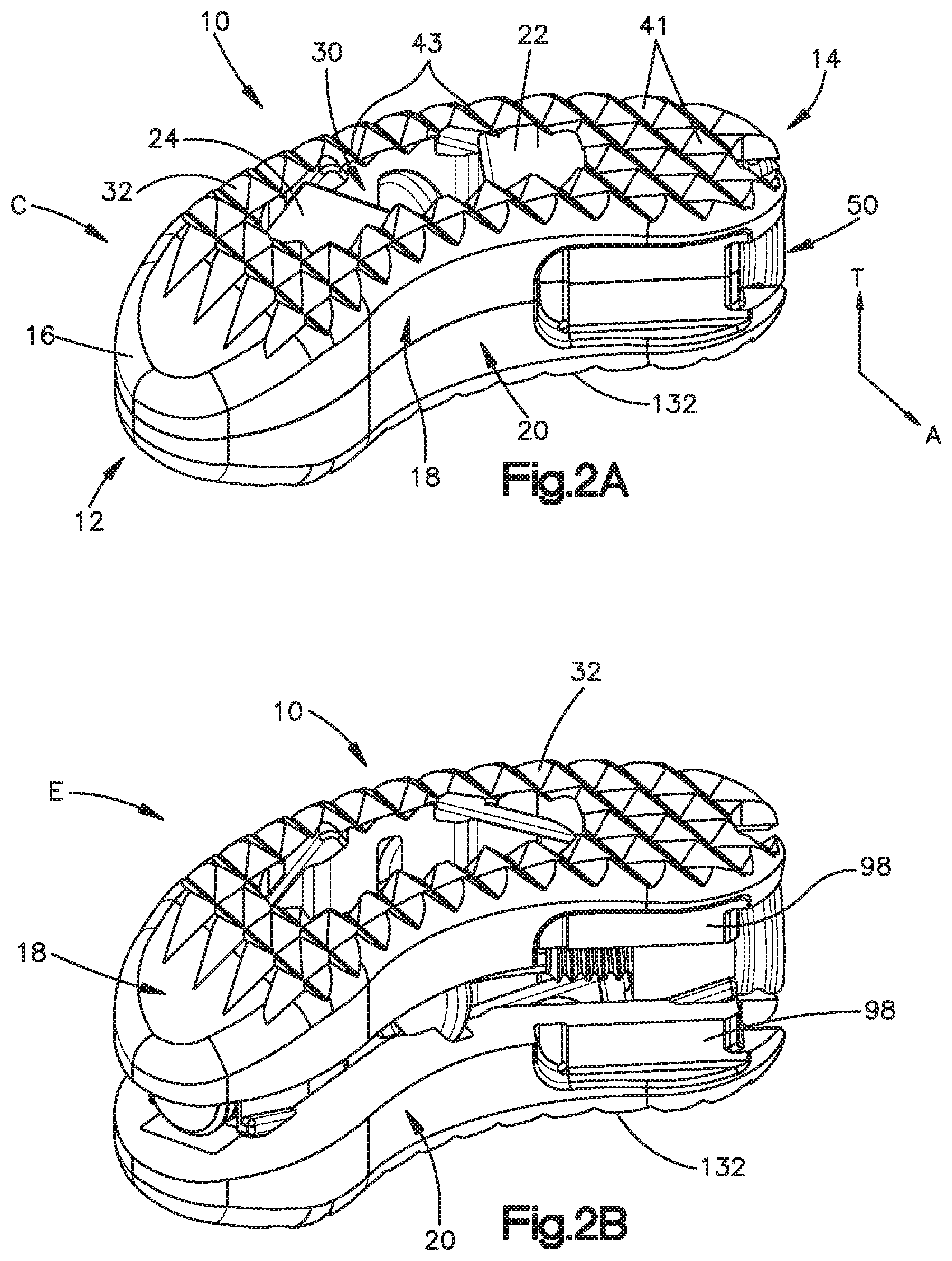
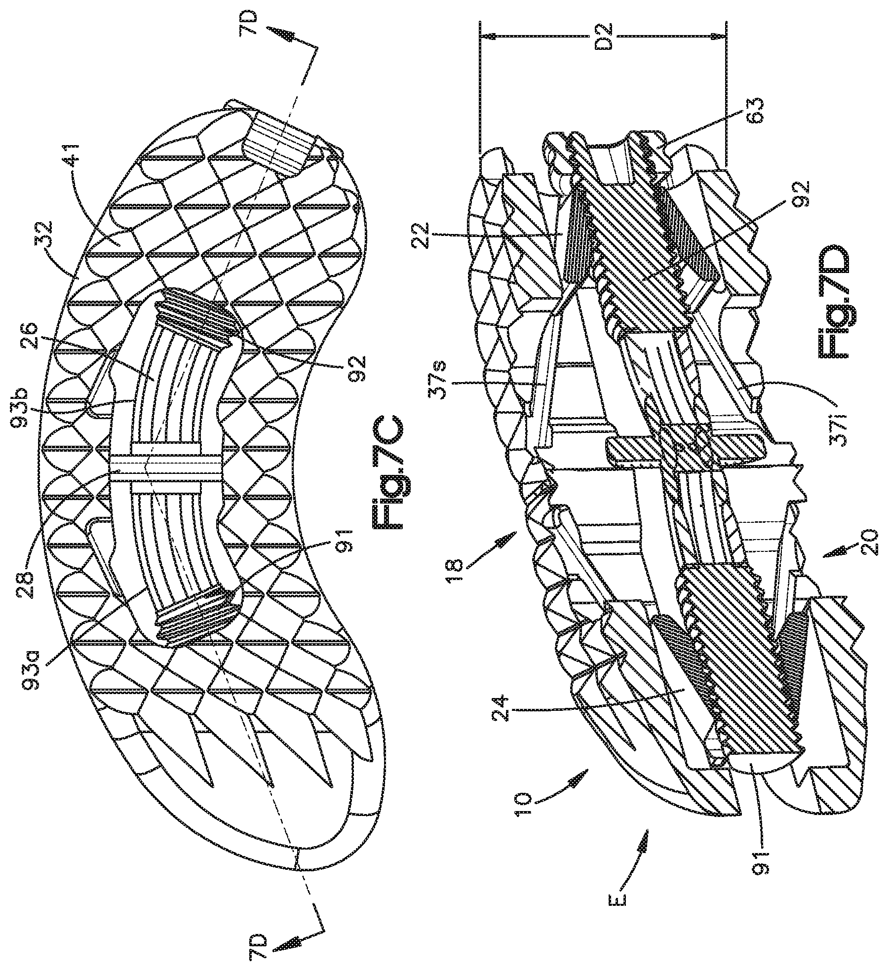
An expandable intervertebral implant includes a first endplate and a second endplate, a first wedge member and a second wedge member spaced from the first wedge member that couple the first and second endplates together. The first and second wedge members are configured to translate along an actuation member housed between the first and second endplates to cause the implant to expand from a first collapsed configuration into a second expanded configuration. The actuation member has a first threaded section spaced apart from a second threaded section where the first and second threaded sections are at an angle with each other. The actuation member is configured to move the first and second wedge members from the first collapsed configuration into the second expanded configuration so that the first and second endplates separate from each other to contact and engage the endplates of the adjacent vertebral bodies.
| Inventors: | Maguire; Paul (Hope Valley, RI), Frasier; William (New Bedford, MA) | ||||||||||
|---|---|---|---|---|---|---|---|---|---|---|---|
| Applicant: |
|
||||||||||
| Assignee: | DePuy Synthes Products, Inc.
(Raynham, MA) |
||||||||||
| Family ID: | 62020618 | ||||||||||
| Appl. No.: | 15/340,448 | ||||||||||
| Filed: | November 1, 2016 |
Prior Publication Data
| Document Identifier | Publication Date | |
|---|---|---|
| US 20180116819 A1 | May 3, 2018 | |
| Current U.S. Class: | 1/1 |
| Current CPC Class: | A61F 2/442 (20130101); A61F 2/4425 (20130101); A61F 2/4465 (20130101); A61F 2/4455 (20130101); A61F 2002/30471 (20130101); A61F 2002/30566 (20130101); A61F 2002/30556 (20130101); A61F 2002/30507 (20130101); A61F 2002/30411 (20130101); A61F 2002/30647 (20130101); A61F 2002/30563 (20130101) |
| Current International Class: | A61F 2/44 (20060101); A61F 2/30 (20060101) |
References Cited [Referenced By]
U.S. Patent Documents
| 1802560 | April 1931 | Kerwin |
| 1924695 | August 1933 | Olson |
| 2077804 | April 1937 | Morrison |
| 2121193 | June 1938 | Hanicke |
| 2173655 | September 1939 | Neracher et al. |
| 2243717 | May 1941 | Moreira |
| 2381050 | August 1945 | Hardinge |
| 2388056 | October 1945 | Hendricks |
| 2485531 | October 1949 | William et al. |
| 2489870 | November 1949 | Dzus |
| 2570465 | October 1951 | Lundholm |
| 2677369 | May 1954 | Knowles |
| 3115804 | December 1963 | Johnson |
| 3312139 | April 1967 | Di Cristina |
| 3486505 | December 1969 | Morrison |
| 3489143 | January 1970 | Halloran |
| 3698391 | October 1972 | Mahony |
| 3760802 | September 1973 | Fischer et al. |
| 3805775 | April 1974 | Fischer et al. |
| 3811449 | May 1974 | Gravlee et al. |
| 3842825 | October 1974 | Wagner |
| 3848601 | November 1974 | Ma et al. |
| 3867728 | February 1975 | Stubstad et al. |
| 3986504 | October 1976 | Avila |
| 4013071 | March 1977 | Rosenberg |
| 4052988 | October 1977 | Doddi et al. |
| 4091806 | May 1978 | Aginsky |
| 4175555 | November 1979 | Herbert |
| 4236512 | December 1980 | Aginsky |
| 4262665 | April 1981 | Roalstad et al. |
| 4275717 | June 1981 | Bolesky |
| 4312353 | January 1982 | Shahbabian |
| 4341206 | July 1982 | Perrett et al. |
| 4349921 | September 1982 | Kuntz |
| 4350151 | September 1982 | Scott |
| 4369790 | January 1983 | McCarthy |
| 4401112 | August 1983 | Rezaian |
| 4401433 | August 1983 | Luther |
| 4409974 | October 1983 | Freedland |
| 4449532 | May 1984 | Storz |
| 4451256 | May 1984 | Weikl et al. |
| 4456005 | June 1984 | Lichty |
| 4463753 | August 1984 | Gustilo |
| 4488543 | December 1984 | Tornier |
| 4494535 | January 1985 | Haig |
| 4532660 | August 1985 | Field |
| 4537185 | August 1985 | Stednitz |
| 4545374 | October 1985 | Jacobson |
| 4573448 | March 1986 | Kambin |
| 4601710 | July 1986 | Moll |
| 4625725 | December 1986 | Davison et al. |
| 4629450 | December 1986 | Suzuki et al. |
| 4632101 | December 1986 | Freedland |
| 4640271 | February 1987 | Lower |
| 4641640 | February 1987 | Griggs |
| 4653489 | March 1987 | Tronzo |
| 4667663 | May 1987 | Miyata |
| 4686984 | August 1987 | Bonnet |
| 4688561 | August 1987 | Reese |
| 4721103 | January 1988 | Freedland |
| 4723544 | February 1988 | Moore et al. |
| 4743256 | May 1988 | Brantigan |
| 4743257 | May 1988 | Toermaelae et al. |
| 4759766 | July 1988 | Buettner-Janz et al. |
| 4760843 | August 1988 | Fischer et al. |
| 4790304 | December 1988 | Rosenberg |
| 4790817 | December 1988 | Luther |
| 4796612 | January 1989 | Reese |
| 4802479 | February 1989 | Haber et al. |
| 4815909 | March 1989 | Simons |
| 4827917 | May 1989 | Brumfield |
| 4858601 | August 1989 | Glisson |
| 4862891 | September 1989 | Smith |
| 4863476 | September 1989 | Shepperd |
| 4871366 | October 1989 | von Recum et al. |
| 4873976 | October 1989 | Schreiber |
| 4878915 | November 1989 | Brantigan |
| 4898186 | February 1990 | Ikada et al. |
| 4903692 | February 1990 | Reese |
| 4917554 | April 1990 | Bronn |
| 4940467 | July 1990 | Tronzo |
| 4959064 | September 1990 | Engelhardt |
| 4963144 | October 1990 | Huene |
| 4966587 | October 1990 | Baumgart |
| 4968317 | November 1990 | Toermaelae et al. |
| 4978334 | December 1990 | Toye et al. |
| 4978349 | December 1990 | Frigg |
| 4981482 | January 1991 | Ichikawa |
| 4988351 | January 1991 | Paulos et al. |
| 4994027 | February 1991 | Farrell |
| 5002557 | March 1991 | Hasson |
| 5011484 | April 1991 | Breard |
| 5013315 | May 1991 | Barrows |
| 5013316 | May 1991 | Goble et al. |
| 5059193 | October 1991 | Kuslich |
| 5062849 | November 1991 | Schelhas |
| 5071437 | December 1991 | Steffee |
| 5080662 | January 1992 | Paul |
| 5084043 | January 1992 | Hertzmann et al. |
| 5092891 | March 1992 | Kummer et al. |
| 5098241 | March 1992 | Aldridge et al. |
| 5098433 | March 1992 | Freedland |
| 5098435 | March 1992 | Stednitz et al. |
| 5114407 | May 1992 | Burbank |
| 5116336 | May 1992 | Frigg |
| 5120171 | June 1992 | Lasner |
| 5122133 | June 1992 | Evans |
| 5122141 | June 1992 | Simpson et al. |
| 5123926 | June 1992 | Pisharodi |
| 5139486 | August 1992 | Moss |
| 5158543 | October 1992 | Lazarus |
| 5167663 | December 1992 | Brumfield |
| 5167664 | December 1992 | Hodorek |
| 5169400 | December 1992 | Muehling et al. |
| 5171278 | December 1992 | Pisharodi |
| 5171279 | December 1992 | Mathews |
| 5171280 | December 1992 | Baumgartner |
| 5176651 | January 1993 | Allgood et al. |
| 5176697 | January 1993 | Hasson et al. |
| 5178501 | January 1993 | Carstairs |
| 5183464 | February 1993 | Dubrul et al. |
| 5188118 | February 1993 | Terwilliger |
| 5195506 | March 1993 | Hulfish |
| 5201742 | April 1993 | Hasson |
| 5217462 | June 1993 | Asnis et al. |
| 5217486 | June 1993 | Rice et al. |
| 5224952 | July 1993 | Deniega et al. |
| 5234431 | August 1993 | Keller |
| 5241972 | September 1993 | Bonati |
| 5242410 | September 1993 | Melker |
| 5242447 | September 1993 | Borzone |
| 5246441 | September 1993 | Ross et al. |
| 5250049 | October 1993 | Michael |
| 5269797 | December 1993 | Bonati et al. |
| 5280782 | January 1994 | Wilk |
| 5286001 | February 1994 | Rafeld |
| 5290243 | March 1994 | Chodorow et al. |
| 5290312 | March 1994 | Kojimoto et al. |
| 5300074 | April 1994 | Frigg |
| 5304142 | April 1994 | Liebl et al. |
| 5308327 | May 1994 | Heaven et al. |
| 5308352 | May 1994 | Koutrouvelis |
| 5312410 | May 1994 | Miller et al. |
| 5312417 | May 1994 | Wilk |
| 5314477 | May 1994 | Marnay |
| 5324261 | June 1994 | Amundson et al. |
| 5334184 | August 1994 | Bimman |
| 5334204 | August 1994 | Clewett et al. |
| 5342365 | August 1994 | Waldman |
| 5342382 | August 1994 | Brinkerhoff et al. |
| 5344252 | September 1994 | Kakimoto |
| 5364398 | November 1994 | Chapman et al. |
| 5370646 | December 1994 | Reese et al. |
| 5370647 | December 1994 | Graber et al. |
| 5370661 | December 1994 | Branch |
| 5370697 | December 1994 | Baumgartner |
| 5382248 | January 1995 | Jacobson et al. |
| 5387213 | February 1995 | Breard et al. |
| 5387215 | February 1995 | Fisher |
| 5390683 | February 1995 | Pishardi |
| 5395317 | March 1995 | Kambin |
| 5395371 | March 1995 | Miller et al. |
| 5401269 | March 1995 | Buttner-Janz et al. |
| 5407430 | April 1995 | Peters |
| 5415661 | May 1995 | Holmes |
| 5424773 | June 1995 | Saito |
| 5425773 | June 1995 | Boyd et al. |
| 5443514 | August 1995 | Steffee |
| 5449359 | September 1995 | Groiso |
| 5449361 | September 1995 | Preissman |
| 5452748 | September 1995 | Simmons et al. |
| 5454790 | October 1995 | Dubrul |
| 5464427 | November 1995 | Curtis et al. |
| 5470333 | November 1995 | Ray |
| 5472426 | December 1995 | Bonati et al. |
| 5474539 | December 1995 | Costa et al. |
| 5486190 | January 1996 | Green |
| 5496318 | March 1996 | Howland et al. |
| 5498265 | March 1996 | Asnis et al. |
| 5501695 | March 1996 | Anspach et al. |
| 5505710 | April 1996 | Dorsey, III |
| 5507816 | April 1996 | Bullivant |
| 5512037 | April 1996 | Russell et al. |
| 5514180 | May 1996 | Heggeness et al. |
| 5520690 | May 1996 | Errico et al. |
| 5520896 | May 1996 | De et al. |
| 5522899 | June 1996 | Michelson |
| 5527312 | June 1996 | Ray |
| 5534029 | July 1996 | Shima |
| 5536127 | July 1996 | Pennig |
| 5540688 | July 1996 | Navas |
| 5540693 | July 1996 | Fisher |
| 5545164 | August 1996 | Howland |
| 5549610 | August 1996 | Russell et al. |
| 5554191 | September 1996 | Lahille et al. |
| 5556431 | September 1996 | Buttner-Janz |
| 5558674 | September 1996 | Heggeness et al. |
| D374287 | October 1996 | Goble et al. |
| 5562738 | October 1996 | Boyd et al. |
| 5564926 | October 1996 | Braanemark |
| 5569248 | October 1996 | Mathews |
| 5569251 | October 1996 | Baker et al. |
| 5569290 | October 1996 | McAfee |
| 5569548 | October 1996 | Koike et al. |
| 5591168 | January 1997 | Judet et al. |
| 5609634 | March 1997 | Voydeville |
| 5609635 | March 1997 | Michelson |
| 5613950 | March 1997 | Yoon |
| 5618142 | April 1997 | Sonden et al. |
| 5618314 | April 1997 | Harwin et al. |
| 5624447 | April 1997 | Myers |
| 5626613 | May 1997 | Schmieding |
| 5628751 | May 1997 | Sander et al. |
| 5628752 | May 1997 | Asnis et al. |
| 5639276 | June 1997 | Weinstock et al. |
| 5643320 | July 1997 | Lower et al. |
| 5645589 | July 1997 | Li |
| 5645599 | July 1997 | Samani |
| 5647857 | July 1997 | Anderson et al. |
| 5649931 | July 1997 | Bryant et al. |
| 5653763 | August 1997 | Errico |
| 5658335 | August 1997 | Allen |
| 5662683 | September 1997 | Kay |
| 5665095 | September 1997 | Jacobson et al. |
| 5665122 | September 1997 | Kambin |
| 5667508 | September 1997 | Errico et al. |
| 5669915 | September 1997 | Caspar et al. |
| 5676701 | October 1997 | Yuan et al. |
| 5683465 | November 1997 | Shinn et al. |
| 5693100 | December 1997 | Pisharodi |
| 5697977 | December 1997 | Pisharodi |
| 5702391 | December 1997 | Lin |
| 5707359 | January 1998 | Bufalini |
| 5713870 | February 1998 | Yoon |
| 5713903 | February 1998 | Sander et al. |
| 5716415 | February 1998 | Steffee |
| 5716416 | February 1998 | Lin |
| 5720753 | February 1998 | Sander et al. |
| 5725541 | March 1998 | Anspach et al. |
| 5725588 | March 1998 | Errico et al. |
| 5728097 | March 1998 | Mathews |
| 5728116 | March 1998 | Rosenman |
| 5735853 | April 1998 | Olerud |
| 5741282 | April 1998 | Anspach et al. |
| 5743881 | April 1998 | Demco |
| 5743912 | April 1998 | Lahille et al. |
| 5743914 | April 1998 | Skiba |
| 5749889 | May 1998 | Bacich et al. |
| 5752969 | May 1998 | Cunci et al. |
| 5762500 | June 1998 | Lazarof |
| 5762629 | June 1998 | Kambin |
| 5772661 | June 1998 | Michelson |
| 5772662 | June 1998 | Chapman et al. |
| 5772678 | June 1998 | Thomason et al. |
| 5776156 | July 1998 | Shikhman |
| 5782800 | July 1998 | Yoon |
| 5782832 | July 1998 | Larsen et al. |
| 5782865 | July 1998 | Grotz |
| 5792044 | August 1998 | Foley et al. |
| 5810721 | September 1998 | Mueller et al. |
| 5810821 | September 1998 | Vandewalle |
| 5810866 | September 1998 | Yoon |
| 5814084 | September 1998 | Grivas et al. |
| 5836948 | November 1998 | Zucherman et al. |
| 5846259 | December 1998 | Berthiaume |
| 5849004 | December 1998 | Bramlet |
| 5851216 | December 1998 | Allen |
| 5860973 | January 1999 | Michelson |
| 5860977 | January 1999 | Zucherman et al. |
| 5865848 | February 1999 | Baker |
| 5871485 | February 1999 | Rao et al. |
| 5873854 | February 1999 | Wolvek |
| 5876404 | March 1999 | Zucherman et al. |
| 5888223 | March 1999 | Bray, Jr. |
| 5888224 | March 1999 | Beckers et al. |
| 5888226 | March 1999 | Rogozinski |
| 5888227 | March 1999 | Cottle |
| 5888228 | March 1999 | Knothe et al. |
| 5893850 | April 1999 | Cachia |
| 5893889 | April 1999 | Harrington |
| 5893890 | April 1999 | Pisharodi |
| 5895428 | April 1999 | Berry |
| 5902231 | May 1999 | Foley et al. |
| 5904696 | May 1999 | Rosenman |
| 5908422 | June 1999 | Bresina |
| 5928235 | July 1999 | Friedl |
| 5928244 | July 1999 | Tovey et al. |
| 5931870 | August 1999 | Cuckler et al. |
| 5935129 | August 1999 | McDevitt et al. |
| 5947999 | September 1999 | Groiso |
| 5948000 | September 1999 | Larsen et al. |
| 5954722 | September 1999 | Bono |
| 5954747 | September 1999 | Clark |
| 5957902 | September 1999 | Teves |
| 5957924 | September 1999 | Toermaelae et al. |
| 5964730 | October 1999 | Williams et al. |
| 5964761 | October 1999 | Kambin |
| 5967783 | October 1999 | Ura |
| 5967970 | October 1999 | Cowan et al. |
| 5968044 | October 1999 | Nicholson et al. |
| 5968098 | October 1999 | Winslow |
| 5976139 | November 1999 | Bramlet |
| 5976146 | November 1999 | Ogawa et al. |
| 5976186 | November 1999 | Bao et al. |
| 5980522 | November 1999 | Koros et al. |
| 5984927 | November 1999 | Wenstrom et al. |
| 5984966 | November 1999 | Kiema et al. |
| 5989255 | November 1999 | Pepper et al. |
| 5989291 | November 1999 | Ralph et al. |
| 5993459 | November 1999 | Larsen et al. |
| 5997510 | December 1999 | Schwemberger |
| 5997538 | December 1999 | Asnis et al. |
| 5997541 | December 1999 | Schenk |
| 6001100 | December 1999 | Sherman et al. |
| 6001101 | December 1999 | Augagneur et al. |
| 6004327 | December 1999 | Asnis et al. |
| 6005161 | December 1999 | Brekke |
| 6007519 | December 1999 | Rosselli |
| 6007566 | December 1999 | Wenstrom, Jr. |
| 6007580 | December 1999 | Lehto et al. |
| 6010513 | January 2000 | Toermaelae et al. |
| 6015410 | January 2000 | Toermaelae et al. |
| 6019762 | February 2000 | Cole |
| 6022352 | February 2000 | Vandewalle |
| 6030162 | February 2000 | Huebner |
| 6030364 | February 2000 | Durgin et al. |
| 6033406 | March 2000 | Mathews |
| 6036701 | March 2000 | Rosenman |
| 6039761 | March 2000 | Li |
| 6039763 | March 2000 | Shelokov |
| 6045579 | April 2000 | Hochshuler |
| 6048309 | April 2000 | Flom et al. |
| 6048342 | April 2000 | Zucherman et al. |
| 6053935 | April 2000 | Brenneman et al. |
| 6066142 | May 2000 | Serbousek et al. |
| 6068630 | May 2000 | Zucherman et al. |
| 6068648 | May 2000 | Cole et al. |
| 6074390 | June 2000 | Zucherman et al. |
| 6080193 | June 2000 | Hochschuler et al. |
| 6083244 | July 2000 | Lubbers et al. |
| 6090112 | July 2000 | Zucherman et al. |
| 6102914 | August 2000 | Bulstra et al. |
| 6102950 | August 2000 | Vaccaro |
| 6106557 | August 2000 | Robioneck et al. |
| 6113637 | September 2000 | Gill et al. |
| 6113638 | September 2000 | Williams et al. |
| 6117174 | September 2000 | Nolan |
| 6123711 | September 2000 | Winters |
| 6126661 | October 2000 | Faccioli et al. |
| 6126663 | October 2000 | Hair |
| 6127597 | October 2000 | Beyar et al. |
| 6129762 | October 2000 | Li |
| 6129763 | October 2000 | Chauvin et al. |
| 6146384 | November 2000 | Lee et al. |
| 6146387 | November 2000 | Trott et al. |
| 6149652 | November 2000 | Zucherman et al. |
| 6152926 | November 2000 | Zucherman et al. |
| 6156038 | December 2000 | Zucherman et al. |
| 6159179 | December 2000 | Simonson |
| 6161350 | December 2000 | Espinosa |
| 6162234 | December 2000 | Freedland et al. |
| 6162236 | December 2000 | Osada |
| 6168595 | January 2001 | Durham et al. |
| 6168597 | January 2001 | Biedermann et al. |
| 6175758 | January 2001 | Kambin |
| 6176882 | January 2001 | Biedermann et al. |
| 6179794 | January 2001 | Burras |
| 6179873 | January 2001 | Zientek |
| 6183471 | February 2001 | Zucherman et al. |
| 6183472 | February 2001 | Lutz |
| 6183474 | February 2001 | Bramlet et al. |
| 6183517 | February 2001 | Suddaby |
| 6190387 | February 2001 | Zucherman et al. |
| 6193757 | February 2001 | Foley et al. |
| 6197041 | March 2001 | Shichman et al. |
| 6200322 | March 2001 | Branch et al. |
| 6206826 | March 2001 | Mathews et al. |
| 6206922 | March 2001 | Zdeblick et al. |
| 6213957 | April 2001 | Milliman et al. |
| 6217509 | April 2001 | Foley et al. |
| 6221082 | April 2001 | Marino et al. |
| 6228058 | May 2001 | Dennis et al. |
| 6231606 | May 2001 | Graf et al. |
| 6235030 | May 2001 | Zucherman et al. |
| 6238397 | May 2001 | Zucherman et al. |
| 6245107 | June 2001 | Ferree |
| 6248108 | June 2001 | Toermaelae et al. |
| 6251111 | June 2001 | Barker et al. |
| 6264676 | July 2001 | Gellman et al. |
| 6267765 | July 2001 | Taylor et al. |
| 6267767 | July 2001 | Strobel et al. |
| 6280444 | August 2001 | Zucherman et al. |
| 6287313 | September 2001 | Sasso |
| 6293909 | September 2001 | Chu et al. |
| 6293952 | September 2001 | Brosens et al. |
| 6296647 | October 2001 | Robioneck et al. |
| 6302914 | October 2001 | Michelson |
| 6306136 | October 2001 | Baccelli |
| 6319254 | November 2001 | Giet et al. |
| 6319272 | November 2001 | Brenneman et al. |
| 6332882 | December 2001 | Zucherman et al. |
| 6332883 | December 2001 | Zucherman et al. |
| 6332895 | December 2001 | Suddaby |
| 6346092 | February 2002 | Leschinsky |
| 6348053 | February 2002 | Cachia |
| 6355043 | March 2002 | Adam |
| 6361537 | March 2002 | Anderson |
| 6361538 | March 2002 | Fenaroli et al. |
| 6361557 | March 2002 | Gittings et al. |
| 6364897 | April 2002 | Bonutti |
| 6368350 | April 2002 | Erickson et al. |
| 6368351 | April 2002 | Glenn |
| 6371971 | April 2002 | Tsugita et al. |
| 6371989 | April 2002 | Chauvin et al. |
| 6375682 | April 2002 | Fleischmann et al. |
| 6379355 | April 2002 | Zucherman et al. |
| 6379363 | April 2002 | Herrington et al. |
| 6387130 | May 2002 | Stone |
| 6409766 | June 2002 | Brett |
| 6409767 | June 2002 | Perice et al. |
| 6419676 | July 2002 | Zucherman et al. |
| 6419677 | July 2002 | Zucherman et al. |
| 6419704 | July 2002 | Ferree |
| 6419705 | July 2002 | Erickson |
| 6419706 | July 2002 | Graf |
| 6423061 | July 2002 | Bryant |
| 6423067 | July 2002 | Eisermann |
| 6425919 | July 2002 | Lambrecht |
| 6428541 | August 2002 | Boyd et al. |
| 6428556 | August 2002 | Chin |
| 6436140 | August 2002 | Liu et al. |
| 6436143 | August 2002 | Ross et al. |
| 6440154 | August 2002 | Gellman et al. |
| 6440169 | August 2002 | Elberg et al. |
| 6443989 | September 2002 | Jackson |
| 6447527 | September 2002 | Thompson et al. |
| 6447540 | September 2002 | Fontaine et al. |
| 6450989 | September 2002 | Dubrul et al. |
| 6451019 | September 2002 | Zucherman et al. |
| 6451020 | September 2002 | Zucherman et al. |
| 6454806 | September 2002 | Cohen et al. |
| 6454807 | September 2002 | Jackson |
| 6458134 | October 2002 | Songer et al. |
| 6468277 | October 2002 | Justin et al. |
| 6468309 | October 2002 | Lieberman |
| 6468310 | October 2002 | Ralph et al. |
| 6471724 | October 2002 | Zdeblick et al. |
| 6475226 | November 2002 | Belef et al. |
| 6478029 | November 2002 | Boyd et al. |
| 6478796 | November 2002 | Zucherman et al. |
| 6485491 | November 2002 | Farris et al. |
| 6485518 | November 2002 | Cornwall et al. |
| 6488693 | December 2002 | Gannoe et al. |
| 6488710 | December 2002 | Besselink |
| 6489309 | December 2002 | Singh et al. |
| 6491714 | December 2002 | Bennett |
| 6494860 | December 2002 | Rocamora et al. |
| 6494893 | December 2002 | Dubrul et al. |
| 6500178 | December 2002 | Zucherman et al. |
| 6506192 | January 2003 | Gertzman et al. |
| 6511481 | January 2003 | Von et al. |
| 6514256 | February 2003 | Zucherman et al. |
| 6517543 | February 2003 | Berrevoets et al. |
| 6517580 | February 2003 | Ramadan et al. |
| 6520907 | February 2003 | Foley et al. |
| 6527774 | March 2003 | Lieberman |
| 6527803 | March 2003 | Crozet et al. |
| 6527804 | March 2003 | Gauchet et al. |
| 6533818 | March 2003 | Weber et al. |
| 6540747 | April 2003 | Marino |
| 6544265 | April 2003 | Lieberman |
| 6547793 | April 2003 | McGuire |
| 6547795 | April 2003 | Schneiderman |
| 6551319 | April 2003 | Lieberman |
| 6551322 | April 2003 | Lieberman |
| 6554831 | April 2003 | Rivard et al. |
| 6554852 | April 2003 | Oberlander |
| 6558389 | May 2003 | Clark et al. |
| 6558424 | May 2003 | Thalgott |
| 6562046 | May 2003 | Sasso |
| 6562049 | May 2003 | Norlander et al. |
| 6562074 | May 2003 | Gerbec et al. |
| 6575979 | June 2003 | Cragg |
| 6576016 | June 2003 | Hochshuler et al. |
| 6579293 | June 2003 | Chandran |
| 6582390 | June 2003 | Sanderson |
| 6582431 | June 2003 | Ray |
| 6582433 | June 2003 | Yun |
| 6582437 | June 2003 | Dorchak et al. |
| 6582441 | June 2003 | He et al. |
| 6582453 | June 2003 | Tran et al. |
| 6582468 | June 2003 | Gauchet |
| 6585730 | July 2003 | Foerster |
| 6585740 | July 2003 | Schlapfer et al. |
| 6589240 | July 2003 | Hinchliffe |
| 6589249 | July 2003 | Sater et al. |
| 6592553 | July 2003 | Zhang et al. |
| 6595998 | July 2003 | Johnson et al. |
| 6596008 | July 2003 | Kambin |
| 6599297 | July 2003 | Carlsson et al. |
| 6607530 | August 2003 | Carl et al. |
| 6610091 | August 2003 | Reiley |
| 6610094 | August 2003 | Husson |
| 6613050 | September 2003 | Wagner et al. |
| 6616678 | September 2003 | Nishtala et al. |
| 6620196 | September 2003 | Trieu |
| 6626944 | September 2003 | Taylor |
| 6632224 | October 2003 | Cachia et al. |
| 6635059 | October 2003 | Randall et al. |
| 6635362 | October 2003 | Zheng |
| 6641564 | November 2003 | Kraus |
| 6641614 | November 2003 | Wagner et al. |
| 6645248 | November 2003 | Casutt |
| 6648890 | November 2003 | Culbert et al. |
| 6648893 | November 2003 | Dudasik |
| 6648917 | November 2003 | Gerbec et al. |
| 6652527 | November 2003 | Zucherman et al. |
| 6655962 | December 2003 | Kennard |
| 6666891 | December 2003 | Boehm et al. |
| 6669698 | December 2003 | Tromanhauser et al. |
| 6669729 | December 2003 | Chin |
| 6669732 | December 2003 | Serhan et al. |
| 6673074 | January 2004 | Shluzas |
| 6676664 | January 2004 | Al-Assir |
| 6676665 | January 2004 | Foley et al. |
| 6679833 | January 2004 | Smith et al. |
| 6682535 | January 2004 | Hoogland |
| 6685706 | February 2004 | Padget et al. |
| 6685742 | February 2004 | Jackson |
| 6689152 | February 2004 | Balceta et al. |
| 6692499 | February 2004 | Toermaelae et al. |
| 6695842 | February 2004 | Zucherman et al. |
| 6695851 | February 2004 | Zdeblick et al. |
| 6699246 | March 2004 | Zucherman et al. |
| 6699247 | March 2004 | Zucherman et al. |
| 6706070 | March 2004 | Wagner et al. |
| 6712819 | March 2004 | Zucherman et al. |
| 6716247 | April 2004 | Michelson |
| 6719760 | April 2004 | Dorchak et al. |
| 6719796 | April 2004 | Cohen et al. |
| 6723096 | April 2004 | Dorchak et al. |
| 6723126 | April 2004 | Berry |
| 6730126 | May 2004 | Boehm et al. |
| 6733093 | May 2004 | Deland et al. |
| 6733460 | May 2004 | Ogura |
| 6733532 | May 2004 | Gauchet et al. |
| 6733534 | May 2004 | Sherman |
| 6733535 | May 2004 | Michelson |
| 6733635 | May 2004 | Ozawa et al. |
| 6740090 | May 2004 | Cragg et al. |
| 6740093 | May 2004 | Hochschuler et al. |
| 6740117 | May 2004 | Ralph et al. |
| 6743166 | June 2004 | Berci et al. |
| 6743255 | June 2004 | Ferree |
| 6746451 | June 2004 | Middleton et al. |
| 6752831 | June 2004 | Sybert et al. |
| 6761720 | July 2004 | Senegas |
| 6770075 | August 2004 | Howland |
| 6773460 | August 2004 | Jackson |
| 6790210 | September 2004 | Cragg et al. |
| 6793656 | September 2004 | Mathews |
| 6793678 | September 2004 | Hawkins |
| 6796983 | September 2004 | Zucherman et al. |
| 6805685 | October 2004 | Taylor |
| 6805695 | October 2004 | Keith et al. |
| 6805714 | October 2004 | Sutcliffe |
| 6808526 | October 2004 | Magerl et al. |
| 6808537 | October 2004 | Michelson |
| 6821298 | November 2004 | Jackson |
| 6830589 | December 2004 | Erickson |
| 6835205 | December 2004 | Atkinson et al. |
| 6835206 | December 2004 | Jackson |
| 6852129 | February 2005 | Gerbec et al. |
| 6855167 | February 2005 | Shimp |
| 6863673 | March 2005 | Gerbec et al. |
| 6875215 | April 2005 | Taras et al. |
| 6881229 | April 2005 | Khandkar et al. |
| 6887243 | May 2005 | Culbert |
| 6890333 | May 2005 | Von et al. |
| 6893464 | May 2005 | Kiester |
| 6893466 | May 2005 | Trieu |
| 6902566 | June 2005 | Zucherman et al. |
| 6908465 | June 2005 | Von et al. |
| 6916323 | July 2005 | Kitchens |
| 6921403 | July 2005 | Cragg et al. |
| 6923811 | August 2005 | Carl et al. |
| 6929606 | August 2005 | Ritland |
| 6936071 | August 2005 | Marnay et al. |
| 6936072 | August 2005 | Lambrecht et al. |
| 6942668 | September 2005 | Padget et al. |
| 6945975 | September 2005 | Dalton |
| 6946000 | September 2005 | Senegas et al. |
| 6949100 | September 2005 | Venturini |
| 6951561 | October 2005 | Warren et al. |
| 6953477 | October 2005 | Berry |
| 6955691 | October 2005 | Chae et al. |
| 6969404 | November 2005 | Ferree |
| 6969405 | November 2005 | Suddaby |
| 6972035 | December 2005 | Michelson |
| 6997929 | February 2006 | Manzi et al. |
| 7004945 | February 2006 | Boyd et al. |
| 7018412 | March 2006 | Ferreira et al. |
| 7018415 | March 2006 | McKay |
| 7018416 | March 2006 | Hanson et al. |
| 7025746 | April 2006 | Tal |
| 7029473 | April 2006 | Zucherman et al. |
| 7037339 | May 2006 | Houfburg et al. |
| 7041107 | May 2006 | Pohjonen et al. |
| 7048736 | May 2006 | Robinson et al. |
| 7060068 | June 2006 | Tromanhauser et al. |
| 7063701 | June 2006 | Michelson |
| 7063702 | June 2006 | Michelson |
| 7066960 | June 2006 | Dickman |
| 7066961 | June 2006 | Michelson |
| 7070601 | July 2006 | Culbert et al. |
| 7074203 | July 2006 | Johanson et al. |
| 7083650 | August 2006 | Moskowitz et al. |
| 7087083 | August 2006 | Pasquet et al. |
| 7094239 | August 2006 | Michelson |
| 7094257 | August 2006 | Mujwid et al. |
| 7094258 | August 2006 | Lambrecht et al. |
| 7101375 | September 2006 | Zucherman et al. |
| 7114501 | October 2006 | Johnson et al. |
| 7118572 | October 2006 | Bramlet et al. |
| 7118579 | October 2006 | Michelson |
| 7118598 | October 2006 | Michelson |
| 7128760 | October 2006 | Michelson |
| 7153305 | December 2006 | Johnson et al. |
| D536096 | January 2007 | Hoogland et al. |
| 7156876 | January 2007 | Moumene et al. |
| 7163558 | January 2007 | Senegas et al. |
| 7172612 | February 2007 | Ishikawa |
| 7179294 | February 2007 | Eisermann et al. |
| 7201751 | April 2007 | Zucherman et al. |
| 7211112 | May 2007 | Baynham et al. |
| 7217293 | May 2007 | Branch |
| 7220280 | May 2007 | Kast et al. |
| 7223292 | May 2007 | Messerli et al. |
| 7226481 | June 2007 | Kuslich |
| 7226483 | June 2007 | Gerber et al. |
| 7235101 | June 2007 | Berry et al. |
| 7238204 | July 2007 | Le et al. |
| 7267683 | September 2007 | Sharkey et al. |
| 7282061 | October 2007 | Sharkey et al. |
| 7306628 | December 2007 | Zucherman et al. |
| 7309357 | December 2007 | Kim |
| 7326211 | February 2008 | Padget et al. |
| 7326248 | February 2008 | Michelson |
| 7335203 | February 2008 | Winslow et al. |
| 7361140 | April 2008 | Ries et al. |
| 7371238 | May 2008 | Soboleski et al. |
| 7377942 | May 2008 | Berry |
| 7400930 | July 2008 | Sharkey et al. |
| 7410501 | August 2008 | Michelson |
| 7413576 | August 2008 | Sybert et al. |
| 7422594 | September 2008 | Zander |
| 7434325 | October 2008 | Foley et al. |
| 7445637 | November 2008 | Taylor |
| D584812 | January 2009 | Ries |
| 7473256 | January 2009 | Assell et al. |
| 7473268 | January 2009 | Zucherman et al. |
| 7476251 | January 2009 | Zucherman et al. |
| 7488326 | February 2009 | Elliott |
| 7503933 | March 2009 | Michelson |
| 7507241 | March 2009 | Levy et al. |
| 7517363 | March 2009 | Rogers |
| 7520888 | April 2009 | Trieu |
| 7547317 | June 2009 | Cragg |
| 7556629 | July 2009 | Von et al. |
| 7556651 | July 2009 | Humphreys et al. |
| 7569074 | August 2009 | Eiserman et al. |
| 7588574 | September 2009 | Assell et al. |
| 7618458 | November 2009 | Biedermann et al. |
| 7621950 | November 2009 | Globerman et al. |
| 7621960 | November 2009 | Boyd et al. |
| 7625378 | December 2009 | Foley |
| 7641657 | January 2010 | Cragg |
| 7641670 | January 2010 | Davison et al. |
| 7647123 | January 2010 | Sharkey et al. |
| 7648523 | January 2010 | Mirkovic et al. |
| 7670354 | March 2010 | Davison et al. |
| 7674273 | March 2010 | Davison et al. |
| 7682370 | March 2010 | Pagliuca et al. |
| 7691120 | April 2010 | Shluzas et al. |
| 7691147 | April 2010 | Gutlin et al. |
| 7699878 | April 2010 | Pavlov et al. |
| 7703727 | April 2010 | Selness |
| 7717944 | May 2010 | Foley et al. |
| 7722530 | May 2010 | Davison |
| 7722612 | May 2010 | Sala et al. |
| 7722674 | May 2010 | Grotz |
| 7727263 | June 2010 | Cragg |
| 7740633 | June 2010 | Assell et al. |
| 7744599 | June 2010 | Cragg |
| 7749270 | July 2010 | Peterman |
| 7762995 | July 2010 | Eversull et al. |
| 7763025 | July 2010 | Ainsworth |
| 7763055 | July 2010 | Foley |
| 7766930 | August 2010 | Dipoto et al. |
| 7771473 | August 2010 | Thramann |
| 7771479 | August 2010 | Humphreys et al. |
| 7785368 | August 2010 | Schaller |
| 7789914 | September 2010 | Michelson |
| 7794463 | September 2010 | Cragg |
| 7799032 | September 2010 | Assell et al. |
| 7799033 | September 2010 | Assell et al. |
| 7799036 | September 2010 | Davison et al. |
| 7799083 | September 2010 | Smith et al. |
| D626233 | October 2010 | Cipoletti et al. |
| 7814429 | October 2010 | Buffet et al. |
| 7819921 | October 2010 | Grotz |
| 7824410 | November 2010 | Simonson et al. |
| 7824429 | November 2010 | Culbert et al. |
| 7824445 | November 2010 | Biro et al. |
| 7837734 | November 2010 | Zucherman et al. |
| 7846183 | December 2010 | Blain |
| 7846206 | December 2010 | Oglaza et al. |
| 7850695 | December 2010 | Pagliuca et al. |
| 7850733 | December 2010 | Baynham et al. |
| 7854766 | December 2010 | Moskowitz et al. |
| 7857832 | December 2010 | Culbert et al. |
| 7862590 | January 2011 | Lim et al. |
| 7862595 | January 2011 | Foley et al. |
| 7867259 | January 2011 | Foley et al. |
| 7874980 | January 2011 | Sonnenschein et al. |
| 7875077 | January 2011 | Humphreys et al. |
| 7879098 | February 2011 | Simmons |
| 7887589 | February 2011 | Glenn et al. |
| 7892171 | February 2011 | Davison et al. |
| 7892249 | February 2011 | Davison et al. |
| 7901438 | March 2011 | Culbert et al. |
| 7901459 | March 2011 | Hodges et al. |
| 7909870 | March 2011 | Kraus |
| 7922729 | April 2011 | Michelson |
| 7931689 | April 2011 | Hochschuler et al. |
| 7938832 | May 2011 | Culbert et al. |
| 7951199 | May 2011 | Miller |
| 7985231 | July 2011 | Sankaran |
| 7993403 | August 2011 | Foley et al. |
| 7998176 | August 2011 | Culbert |
| 8021424 | September 2011 | Beger et al. |
| 8021426 | September 2011 | Segal et al. |
| 8025697 | September 2011 | McClellan et al. |
| 8034109 | October 2011 | Zwirkoski |
| 8043381 | October 2011 | Hestad et al. |
| 8062375 | November 2011 | Glerum et al. |
| 8075621 | December 2011 | Michelson |
| 8105382 | January 2012 | Olmos et al. |
| 8109977 | February 2012 | Culbert et al. |
| 8118871 | February 2012 | Gordon |
| 8128700 | March 2012 | Delurio et al. |
| 8133232 | March 2012 | Levy et al. |
| 8177812 | May 2012 | Sankaran |
| 8192495 | June 2012 | Simpson et al. |
| 8221501 | July 2012 | Eiserman et al. |
| 8221502 | July 2012 | Branch |
| 8221503 | July 2012 | Garcia et al. |
| 8231681 | July 2012 | Castleman et al. |
| 8236058 | August 2012 | Fabian et al. |
| 8241358 | August 2012 | Butler et al. |
| 8257440 | September 2012 | Gordon et al. |
| 8257442 | September 2012 | Edie et al. |
| 8262666 | September 2012 | Baynham et al. |
| 8262736 | September 2012 | Michelson |
| 8267939 | September 2012 | Cipoletti et al. |
| 8273128 | September 2012 | Oh et al. |
| 8273129 | September 2012 | Baynham et al. |
| 8287599 | October 2012 | McGuckin |
| 8303663 | November 2012 | Jimenez et al. |
| 8317866 | November 2012 | Palmatier et al. |
| 8323345 | December 2012 | Sledge |
| 8328852 | December 2012 | Zehavi et al. |
| 8337559 | December 2012 | Hansell et al. |
| 8353961 | January 2013 | McClintock |
| 8366777 | February 2013 | Matthis et al. |
| 8382842 | February 2013 | Greenhalgh et al. |
| 8394129 | March 2013 | Morgenstern et al. |
| 8398713 | March 2013 | Weiman |
| 8403990 | March 2013 | Dryer et al. |
| 8409291 | April 2013 | Blackwell et al. |
| 8435298 | May 2013 | Weiman |
| 8454617 | June 2013 | Schaller |
| 8486148 | July 2013 | Butler et al. |
| 8491657 | July 2013 | Attia et al. |
| 8491659 | July 2013 | Weiman |
| 8506635 | August 2013 | Palmatier et al. |
| 8518087 | August 2013 | Morgenstern et al. |
| 8518120 | August 2013 | Glerum et al. |
| 8535380 | September 2013 | Greenhalgh et al. |
| 8551173 | October 2013 | Lechmann et al. |
| 8556979 | October 2013 | Glerum et al. |
| 8568481 | October 2013 | Olmos et al. |
| 8579977 | November 2013 | Fabian |
| 8579981 | November 2013 | Lim |
| 8591585 | November 2013 | McLaughlin et al. |
| 8597333 | December 2013 | Morgenstern et al. |
| 8603170 | December 2013 | Cipoletti et al. |
| 8623091 | January 2014 | Suedkamp et al. |
| 8628576 | January 2014 | Triplett et al. |
| 8628578 | January 2014 | Miller et al. |
| 8632595 | January 2014 | Weiman |
| 8663329 | March 2014 | Ernst |
| 8668740 | March 2014 | Rhoda et al. |
| 8679183 | March 2014 | Glerum et al. |
| 8685098 | April 2014 | Glerum et al. |
| 8696751 | April 2014 | Ashley et al. |
| 8709086 | April 2014 | Glerum et al. |
| 8715351 | May 2014 | Pinto |
| 8721723 | May 2014 | Hansell et al. |
| 8728160 | May 2014 | Globerman et al. |
| 8753398 | June 2014 | Gordon et al. |
| 8771360 | July 2014 | Jimenez et al. |
| 8778025 | July 2014 | Ragab et al. |
| 8795366 | August 2014 | Varela |
| 8828085 | September 2014 | Jensen |
| 8845731 | September 2014 | Weiman |
| 8845732 | September 2014 | Weiman |
| 8845734 | September 2014 | Weiman |
| 8852242 | October 2014 | Morgenstern et al. |
| 8852243 | October 2014 | Morgenstern et al. |
| 8852279 | October 2014 | Weiman |
| 8864833 | October 2014 | Glerum et al. |
| 8888853 | November 2014 | Glerum et al. |
| 8888854 | November 2014 | Glerum et al. |
| 8900307 | December 2014 | Hawkins et al. |
| 8926704 | January 2015 | Glerum |
| 8936641 | January 2015 | Cain |
| 8940052 | January 2015 | Lechmann et al. |
| 8986387 | March 2015 | To et al. |
| 9005291 | April 2015 | Loebl et al. |
| 9039767 | May 2015 | Raymond et al. |
| 9039771 | May 2015 | Glerum et al. |
| 9060876 | June 2015 | To et al. |
| 9078767 | July 2015 | McLean |
| 9091488 | August 2015 | Malandain |
| 9095446 | August 2015 | Landry et al. |
| 9095447 | August 2015 | Barreiro et al. |
| 9101488 | August 2015 | Malandain |
| 9101489 | August 2015 | Protopsaltis et al. |
| 9107766 | August 2015 | Mclean et al. |
| 9277928 | March 2016 | Morgenstern |
| 9295562 | March 2016 | Lechmann et al. |
| 9402739 | August 2016 | Weiman et al. |
| 9433510 | September 2016 | Lechmann et al. |
| 9463099 | October 2016 | Levy et al. |
| 9510954 | December 2016 | Glerum et al. |
| 9597197 | March 2017 | Lechmann et al. |
| 10307254 | June 2019 | Levy |
| 2001/0012950 | August 2001 | Nishtala et al. |
| 2001/0027320 | October 2001 | Sasso |
| 2001/0037126 | November 2001 | Stack et al. |
| 2001/0039452 | November 2001 | Zucherman et al. |
| 2001/0049529 | December 2001 | Cachia et al. |
| 2001/0049530 | December 2001 | Culbert et al. |
| 2002/0001476 | January 2002 | Nagamine et al. |
| 2002/0010070 | January 2002 | Cales et al. |
| 2002/0032462 | March 2002 | Houser et al. |
| 2002/0055740 | May 2002 | Lieberman |
| 2002/0068976 | June 2002 | Jackson |
| 2002/0068977 | June 2002 | Jackson |
| 2002/0087152 | July 2002 | Mikus et al. |
| 2002/0091387 | July 2002 | Hoogland |
| 2002/0120335 | August 2002 | Angelucci et al. |
| 2002/0128715 | September 2002 | Bryan et al. |
| 2002/0128716 | September 2002 | Cohen et al. |
| 2002/0138146 | September 2002 | Jackson |
| 2002/0143331 | October 2002 | Zucherman et al. |
| 2002/0143334 | October 2002 | Hoffmann et al. |
| 2002/0143335 | October 2002 | Von et al. |
| 2002/0151895 | October 2002 | Soboleski et al. |
| 2002/0151976 | October 2002 | Foley et al. |
| 2002/0161444 | October 2002 | Choi |
| 2002/0165612 | November 2002 | Gerber et al. |
| 2002/0183848 | December 2002 | Ray et al. |
| 2003/0004575 | January 2003 | Erickson |
| 2003/0004576 | January 2003 | Thalgott |
| 2003/0023305 | January 2003 | McKay |
| 2003/0028250 | February 2003 | Reiley et al. |
| 2003/0040799 | February 2003 | Boyd et al. |
| 2003/0063582 | April 2003 | Mizell et al. |
| 2003/0065330 | April 2003 | Zucherman et al. |
| 2003/0065396 | April 2003 | Michelson |
| 2003/0069582 | April 2003 | Culbert |
| 2003/0078667 | April 2003 | Manasas et al. |
| 2003/0083688 | May 2003 | Simonson |
| 2003/0130739 | July 2003 | Gerbec et al. |
| 2003/0135275 | July 2003 | Garcia |
| 2003/0139648 | July 2003 | Foley et al. |
| 2003/0139812 | July 2003 | Garcia |
| 2003/0139813 | July 2003 | Messerli et al. |
| 2003/0153874 | August 2003 | Tal |
| 2003/0187431 | October 2003 | Simonson |
| 2003/0204261 | October 2003 | Eiserman |
| 2003/0208122 | November 2003 | Melkent et al. |
| 2003/0208220 | November 2003 | Worley et al. |
| 2003/0220643 | November 2003 | Ferree |
| 2003/0229350 | December 2003 | Kay |
| 2003/0233102 | December 2003 | Nakamura et al. |
| 2003/0233145 | December 2003 | Landry et al. |
| 2004/0006391 | January 2004 | Reiley |
| 2004/0008949 | January 2004 | Liu et al. |
| 2004/0019359 | January 2004 | Worley et al. |
| 2004/0024463 | February 2004 | Thomas et al. |
| 2004/0030387 | February 2004 | Landry et al. |
| 2004/0049190 | March 2004 | Biedermann et al. |
| 2004/0049223 | March 2004 | Nishtala et al. |
| 2004/0054412 | March 2004 | Gerbec et al. |
| 2004/0059339 | March 2004 | Roehm et al. |
| 2004/0059350 | March 2004 | Gordon et al. |
| 2004/0064144 | April 2004 | Johnson et al. |
| 2004/0087947 | May 2004 | Lim |
| 2004/0088055 | May 2004 | Hanson et al. |
| 2004/0093083 | May 2004 | Branch |
| 2004/0097924 | May 2004 | Lambrecht et al. |
| 2004/0097941 | May 2004 | Weiner et al. |
| 2004/0097973 | May 2004 | Loshakove et al. |
| 2004/0106925 | June 2004 | Culbert |
| 2004/0127906 | July 2004 | Culbert et al. |
| 2004/0127991 | July 2004 | Ferree |
| 2004/0133280 | July 2004 | Trieu |
| 2004/0143284 | July 2004 | Chin |
| 2004/0143734 | July 2004 | Buer et al. |
| 2004/0147877 | July 2004 | Heuser |
| 2004/0147950 | July 2004 | Mueller et al. |
| 2004/0148027 | July 2004 | Errico et al. |
| 2004/0153065 | August 2004 | Lim |
| 2004/0153156 | August 2004 | Cohen et al. |
| 2004/0153160 | August 2004 | Carrasco |
| 2004/0158258 | August 2004 | Bonati et al. |
| 2004/0162617 | August 2004 | Zucherman et al. |
| 2004/0162618 | August 2004 | Mujwid et al. |
| 2004/0172133 | September 2004 | Gerber et al. |
| 2004/0186471 | September 2004 | Trieu |
| 2004/0186482 | September 2004 | Kolb et al. |
| 2004/0186570 | September 2004 | Rapp |
| 2004/0186577 | September 2004 | Ferree |
| 2004/0199162 | October 2004 | Von et al. |
| 2004/0215343 | October 2004 | Hochschuler et al. |
| 2004/0215344 | October 2004 | Hochschuler et al. |
| 2004/0220580 | November 2004 | Johnson et al. |
| 2004/0225292 | November 2004 | Sasso et al. |
| 2004/0225361 | November 2004 | Glenn et al. |
| 2004/0230309 | November 2004 | DiMauro |
| 2004/0243239 | December 2004 | Taylor |
| 2004/0249466 | December 2004 | Liu et al. |
| 2004/0254575 | December 2004 | Obenchain et al. |
| 2004/0260297 | December 2004 | Padget et al. |
| 2004/0266257 | December 2004 | Ries et al. |
| 2005/0019365 | January 2005 | Frauchiger et al. |
| 2005/0033289 | February 2005 | Warren et al. |
| 2005/0033434 | February 2005 | Berry |
| 2005/0038515 | February 2005 | Kunzler |
| 2005/0043796 | February 2005 | Grant et al. |
| 2005/0065610 | March 2005 | Pisharodi |
| 2005/0090443 | April 2005 | Michael John |
| 2005/0090833 | April 2005 | Dipoto |
| 2005/0102202 | May 2005 | Linden et al. |
| 2005/0113916 | May 2005 | Branch |
| 2005/0113917 | May 2005 | Chae et al. |
| 2005/0113927 | May 2005 | Malek |
| 2005/0118550 | June 2005 | Turri |
| 2005/0119657 | June 2005 | Goldsmith |
| 2005/0125062 | June 2005 | Biedermann et al. |
| 2005/0130929 | June 2005 | Boyd |
| 2005/0131406 | June 2005 | Reiley et al. |
| 2005/0131409 | June 2005 | Chervitz et al. |
| 2005/0131411 | June 2005 | Culbert |
| 2005/0131538 | June 2005 | Chervitz et al. |
| 2005/0137595 | June 2005 | Hoffmann et al. |
| 2005/0143734 | June 2005 | Cachia et al. |
| 2005/0149030 | July 2005 | Serhan et al. |
| 2005/0154467 | July 2005 | Peterman et al. |
| 2005/0165398 | July 2005 | Reiley |
| 2005/0165485 | July 2005 | Trieu |
| 2005/0171552 | August 2005 | Johnson et al. |
| 2005/0171608 | August 2005 | Peterman et al. |
| 2005/0171610 | August 2005 | Humphreys et al. |
| 2005/0177235 | August 2005 | Baynham et al. |
| 2005/0177240 | August 2005 | Blain |
| 2005/0182414 | August 2005 | Manzi et al. |
| 2005/0182418 | August 2005 | Boyd et al. |
| 2005/0187558 | August 2005 | Johnson et al. |
| 2005/0187559 | August 2005 | Raymond et al. |
| 2005/0203512 | September 2005 | Hawkins et al. |
| 2005/0216026 | September 2005 | Culbert |
| 2005/0222681 | October 2005 | Richley et al. |
| 2005/0251142 | November 2005 | Hoffmann et al. |
| 2005/0256525 | November 2005 | Culbert et al. |
| 2005/0256576 | November 2005 | Moskowitz et al. |
| 2005/0261769 | November 2005 | Moskowitz et al. |
| 2005/0278026 | December 2005 | Gordon et al. |
| 2005/0283238 | December 2005 | Reiley |
| 2006/0004326 | January 2006 | Collins et al. |
| 2006/0004457 | January 2006 | Collins et al. |
| 2006/0004458 | January 2006 | Collins et al. |
| 2006/0009778 | January 2006 | Collins et al. |
| 2006/0009779 | January 2006 | Collins et al. |
| 2006/0009851 | January 2006 | Collins et al. |
| 2006/0015105 | January 2006 | Warren et al. |
| 2006/0020284 | January 2006 | Foley et al. |
| 2006/0030872 | February 2006 | Culbert et al. |
| 2006/0036246 | February 2006 | Carl et al. |
| 2006/0036256 | February 2006 | Carl et al. |
| 2006/0036259 | February 2006 | Carl et al. |
| 2006/0036323 | February 2006 | Carl et al. |
| 2006/0036324 | February 2006 | Sachs et al. |
| 2006/0041314 | February 2006 | Millard |
| 2006/0052788 | March 2006 | Thelen et al. |
| 2006/0058790 | March 2006 | Carl et al. |
| 2006/0058807 | March 2006 | Landry et al. |
| 2006/0058876 | March 2006 | McKinley |
| 2006/0058880 | March 2006 | Wysocki |
| 2006/0079908 | April 2006 | Lieberman |
| 2006/0084977 | April 2006 | Lieberman |
| 2006/0084988 | April 2006 | Kim |
| 2006/0085010 | April 2006 | Lieberman |
| 2006/0100706 | May 2006 | Shadduck et al. |
| 2006/0100707 | May 2006 | Stinson et al. |
| 2006/0106381 | May 2006 | Ferree et al. |
| 2006/0119629 | June 2006 | An et al. |
| 2006/0122609 | June 2006 | Mirkovic et al. |
| 2006/0122610 | June 2006 | Culbert et al. |
| 2006/0122701 | June 2006 | Kiester |
| 2006/0122703 | June 2006 | Aebi et al. |
| 2006/0129244 | June 2006 | Ensign |
| 2006/0136062 | June 2006 | DiNello et al. |
| 2006/0142759 | June 2006 | Arnin et al. |
| 2006/0142765 | June 2006 | Dixon et al. |
| 2006/0142776 | June 2006 | Iwanari |
| 2006/0142858 | June 2006 | Colleran et al. |
| 2006/0161166 | July 2006 | Johnson et al. |
| 2006/0178743 | August 2006 | Carter |
| 2006/0195103 | August 2006 | Padget et al. |
| 2006/0206207 | September 2006 | Dryer et al. |
| 2006/0217711 | September 2006 | Stevens et al. |
| 2006/0229629 | October 2006 | Manzi et al. |
| 2006/0235403 | October 2006 | Blain |
| 2006/0235412 | October 2006 | Blain |
| 2006/0235531 | October 2006 | Buettner |
| 2006/0247634 | November 2006 | Warner et al. |
| 2006/0253201 | November 2006 | McLuen |
| 2006/0265075 | November 2006 | Baumgartner et al. |
| 2006/0265077 | November 2006 | Zwirkoski |
| 2006/0276899 | December 2006 | Zipnick et al. |
| 2006/0276901 | December 2006 | Zipnick et al. |
| 2006/0276902 | December 2006 | Zipnick et al. |
| 2006/0293662 | December 2006 | Boyer et al. |
| 2006/0293663 | December 2006 | Walkenhorst et al. |
| 2007/0010826 | January 2007 | Rhoda et al. |
| 2007/0010886 | January 2007 | Banick et al. |
| 2007/0016191 | January 2007 | Culbert et al. |
| 2007/0032790 | February 2007 | Aschmann et al. |
| 2007/0055236 | March 2007 | Hudgins et al. |
| 2007/0055377 | March 2007 | Hanson et al. |
| 2007/0067035 | March 2007 | Falahee |
| 2007/0073399 | March 2007 | Zipnick et al. |
| 2007/0118132 | May 2007 | Culbert et al. |
| 2007/0118222 | May 2007 | Lang |
| 2007/0118223 | May 2007 | Allard et al. |
| 2007/0123868 | May 2007 | Culbert et al. |
| 2007/0123891 | May 2007 | Ries et al. |
| 2007/0123892 | May 2007 | Ries et al. |
| 2007/0129730 | June 2007 | Woods et al. |
| 2007/0149978 | June 2007 | Shezifi et al. |
| 2007/0162005 | July 2007 | Peterson et al. |
| 2007/0162138 | July 2007 | Heinz |
| 2007/0168036 | July 2007 | Ainsworth et al. |
| 2007/0173939 | July 2007 | Kim et al. |
| 2007/0173940 | July 2007 | Hestad et al. |
| 2007/0178222 | August 2007 | Storey et al. |
| 2007/0191954 | August 2007 | Hansell et al. |
| 2007/0191959 | August 2007 | Hartmann et al. |
| 2007/0198089 | August 2007 | Moskowitz et al. |
| 2007/0203491 | August 2007 | Pasquet et al. |
| 2007/0208423 | September 2007 | Messerli et al. |
| 2007/0219634 | September 2007 | Greenhalgh et al. |
| 2007/0233083 | October 2007 | Abdou |
| 2007/0233089 | October 2007 | Dipoto et al. |
| 2007/0233244 | October 2007 | Lopez et al. |
| 2007/0270954 | November 2007 | Wu |
| 2007/0270968 | November 2007 | Baynham et al. |
| 2007/0276375 | November 2007 | Rapp |
| 2007/0282449 | December 2007 | De et al. |
| 2007/0299521 | December 2007 | Glenn |
| 2008/0009877 | January 2008 | Sankaran et al. |
| 2008/0015701 | January 2008 | Garcia et al. |
| 2008/0021556 | January 2008 | Edie |
| 2008/0021558 | January 2008 | Thramann |
| 2008/0027550 | January 2008 | Link et al. |
| 2008/0033440 | February 2008 | Moskowitz et al. |
| 2008/0058598 | March 2008 | Ries et al. |
| 2008/0058944 | March 2008 | Duplessis et al. |
| 2008/0065219 | March 2008 | Dye |
| 2008/0077148 | March 2008 | Ries et al. |
| 2008/0082172 | April 2008 | Jackson |
| 2008/0082173 | April 2008 | Delurio et al. |
| 2008/0097436 | April 2008 | Culbert et al. |
| 2008/0108996 | May 2008 | Padget et al. |
| 2008/0132934 | June 2008 | Reilly |
| 2008/0140207 | June 2008 | Olmos |
| 2008/0147193 | June 2008 | Matthis |
| 2008/0161927 | July 2008 | Savage |
| 2008/0167657 | July 2008 | Greenhalgh |
| 2008/0177388 | July 2008 | Patterson et al. |
| 2008/0183204 | July 2008 | Greenhalgh et al. |
| 2008/0195209 | August 2008 | Garcia et al. |
| 2008/0243251 | October 2008 | Stad et al. |
| 2008/0243254 | October 2008 | Butler |
| 2008/0249622 | October 2008 | Gray |
| 2008/0255618 | October 2008 | Fisher et al. |
| 2008/0262619 | October 2008 | Ray |
| 2008/0269904 | October 2008 | Voorhies |
| 2008/0281425 | November 2008 | Thalgott |
| 2008/0287981 | November 2008 | Culbert et al. |
| 2008/0287997 | November 2008 | Altarac et al. |
| 2008/0300685 | December 2008 | Carls et al. |
| 2008/0306537 | December 2008 | Culbert |
| 2009/0005870 | January 2009 | Hawkins et al. |
| 2009/0005873 | January 2009 | Slivka et al. |
| 2009/0030423 | January 2009 | Puno |
| 2009/0048631 | February 2009 | Bhatnagar |
| 2009/0054991 | February 2009 | Biyani |
| 2009/0069813 | March 2009 | Von et al. |
| 2009/0076610 | March 2009 | Afzal |
| 2009/0099568 | April 2009 | Lowry et al. |
| 2009/0105745 | April 2009 | Culbert |
| 2009/0112320 | April 2009 | Kraus |
| 2009/0112324 | April 2009 | Refai et al. |
| 2009/0131986 | May 2009 | Lee et al. |
| 2009/0149857 | June 2009 | Culbert et al. |
| 2009/0164020 | June 2009 | Janowski |
| 2009/0177284 | July 2009 | Rogers et al. |
| 2009/0182429 | July 2009 | Humphreys et al. |
| 2009/0192614 | July 2009 | Beger et al. |
| 2009/0222096 | September 2009 | Trieu |
| 2009/0222099 | September 2009 | Liu et al. |
| 2009/0222100 | September 2009 | Cipoletti et al. |
| 2009/0234398 | September 2009 | Chirico et al. |
| 2009/0240335 | September 2009 | Arcenio et al. |
| 2009/0248159 | October 2009 | Aflatoon |
| 2009/0275890 | November 2009 | Leibowitz et al. |
| 2009/0292361 | November 2009 | Lopez et al. |
| 2010/0016905 | January 2010 | Greenhalgh et al. |
| 2010/0040332 | February 2010 | Van et al. |
| 2010/0076492 | March 2010 | Warner et al. |
| 2010/0076559 | March 2010 | Bagga |
| 2010/0082109 | April 2010 | Greenhalgh et al. |
| 2010/0094424 | April 2010 | Woodburn et al. |
| 2010/0114147 | May 2010 | Biyani |
| 2010/0174314 | July 2010 | Mirkovic et al. |
| 2010/0179594 | July 2010 | Theofilos et al. |
| 2010/0191336 | July 2010 | Greenhalgh |
| 2010/0204795 | August 2010 | Greenhalgh |
| 2010/0211176 | August 2010 | Greenhalgh |
| 2010/0234956 | September 2010 | Attia et al. |
| 2010/0262240 | October 2010 | Chavatte et al. |
| 2010/0268231 | October 2010 | Kuslich et al. |
| 2010/0286783 | November 2010 | Lechmann et al. |
| 2010/0292700 | November 2010 | Ries |
| 2010/0298938 | November 2010 | Humphreys et al. |
| 2010/0324607 | December 2010 | Davis |
| 2010/0331891 | December 2010 | Culbert et al. |
| 2011/0004308 | January 2011 | Marino et al. |
| 2011/0004310 | January 2011 | Michelson |
| 2011/0015747 | January 2011 | McManus et al. |
| 2011/0029082 | February 2011 | Hall |
| 2011/0035011 | February 2011 | Cain |
| 2011/0054538 | March 2011 | Zehavi et al. |
| 2011/0071527 | March 2011 | Nelson et al. |
| 2011/0093074 | April 2011 | Glerum et al. |
| 2011/0098531 | April 2011 | To |
| 2011/0098628 | April 2011 | Yeung et al. |
| 2011/0130835 | June 2011 | Ashley et al. |
| 2011/0130838 | June 2011 | Morgenstern et al. |
| 2011/0144692 | June 2011 | Saladin et al. |
| 2011/0144753 | June 2011 | Marchek et al. |
| 2011/0153020 | June 2011 | Abdelgany et al. |
| 2011/0172716 | July 2011 | Glerum |
| 2011/0172774 | July 2011 | Varela |
| 2011/0238072 | September 2011 | Tyndall |
| 2011/0270261 | November 2011 | Mast et al. |
| 2011/0270401 | November 2011 | McKay |
| 2011/0282453 | November 2011 | Greenhalgh et al. |
| 2011/0301711 | December 2011 | Palmatier et al. |
| 2011/0301712 | December 2011 | Palmatier et al. |
| 2011/0307010 | December 2011 | Pradhan |
| 2011/0313465 | December 2011 | Warren et al. |
| 2011/0320000 | December 2011 | O'Neil |
| 2012/0004726 | January 2012 | Greenhalgh et al. |
| 2012/0004732 | January 2012 | Goel et al. |
| 2012/0022654 | January 2012 | Farris et al. |
| 2012/0029636 | February 2012 | Ragab et al. |
| 2012/0059474 | March 2012 | Weiman |
| 2012/0059475 | March 2012 | Weiman |
| 2012/0071977 | March 2012 | Oglaza et al. |
| 2012/0071980 | March 2012 | Purcell et al. |
| 2012/0083889 | April 2012 | Purcell et al. |
| 2012/0123546 | May 2012 | Medina |
| 2012/0150304 | June 2012 | Glerum et al. |
| 2012/0150305 | June 2012 | Glerum et al. |
| 2012/0158146 | June 2012 | Glerum et al. |
| 2012/0158147 | June 2012 | Glerum et al. |
| 2012/0158148 | June 2012 | Glerum et al. |
| 2012/0185049 | July 2012 | Varela |
| 2012/0197299 | August 2012 | Fabian, Jr. |
| 2012/0197403 | August 2012 | Merves |
| 2012/0197405 | August 2012 | Cuevas et al. |
| 2012/0203290 | August 2012 | Warren et al. |
| 2012/0203347 | August 2012 | Glerum et al. |
| 2012/0215262 | August 2012 | Culbert et al. |
| 2012/0215316 | August 2012 | Mohr |
| 2012/0226357 | September 2012 | Varela |
| 2012/0232552 | September 2012 | Morgenstern et al. |
| 2012/0232658 | September 2012 | Morgenstern et al. |
| 2012/0265309 | October 2012 | Glerum et al. |
| 2012/0277795 | November 2012 | Von et al. |
| 2012/0290090 | November 2012 | Glerum et al. |
| 2012/0290097 | November 2012 | Cipoletti et al. |
| 2012/0310350 | December 2012 | Farris et al. |
| 2012/0310352 | December 2012 | DiMauro et al. |
| 2012/0323327 | December 2012 | McAfee |
| 2012/0323328 | December 2012 | Weiman |
| 2012/0330421 | December 2012 | Weiman |
| 2012/0330422 | December 2012 | Weiman |
| 2013/0006361 | January 2013 | Glerum et al. |
| 2013/0023993 | January 2013 | Weiman |
| 2013/0023994 | January 2013 | Glerum |
| 2013/0030536 | January 2013 | Rhoda et al. |
| 2013/0085572 | April 2013 | Glerum et al. |
| 2013/0085574 | April 2013 | Sledge |
| 2013/0116791 | May 2013 | Theofilos |
| 2013/0123924 | May 2013 | Butler et al. |
| 2013/0123927 | May 2013 | Malandain |
| 2013/0138214 | May 2013 | Greenhalgh et al. |
| 2013/0144387 | June 2013 | Walker et al. |
| 2013/0144388 | June 2013 | Emery et al. |
| 2013/0158663 | June 2013 | Miller et al. |
| 2013/0158664 | June 2013 | Palmatier et al. |
| 2013/0158667 | June 2013 | Tabor et al. |
| 2013/0158668 | June 2013 | Nichols et al. |
| 2013/0158669 | June 2013 | Sungarian et al. |
| 2013/0173004 | July 2013 | Greenhalgh et al. |
| 2013/0190876 | July 2013 | Drochner et al. |
| 2013/0190877 | July 2013 | Medina |
| 2013/0204371 | August 2013 | McLuen et al. |
| 2013/0211525 | August 2013 | McLuen et al. |
| 2013/0211526 | August 2013 | Alheidt et al. |
| 2013/0310939 | November 2013 | Fabian et al. |
| 2013/0325128 | December 2013 | Perloff et al. |
| 2014/0025169 | January 2014 | Lechmann et al. |
| 2014/0039622 | February 2014 | Glerum et al. |
| 2014/0046333 | February 2014 | Johnson et al. |
| 2014/0058513 | February 2014 | Gahman et al. |
| 2014/0067073 | March 2014 | Hauck |
| 2014/0094916 | April 2014 | Glerum et al. |
| 2014/0100662 | April 2014 | Patterson |
| 2014/0114423 | April 2014 | Suedkamp et al. |
| 2014/0128977 | May 2014 | Glerum et al. |
| 2014/0135934 | May 2014 | Hansell et al. |
| 2014/0142706 | May 2014 | Hansell et al. |
| 2014/0163682 | June 2014 | Lott |
| 2014/0163683 | June 2014 | Seifert et al. |
| 2014/0172106 | June 2014 | To et al. |
| 2014/0180421 | June 2014 | Glerum et al. |
| 2014/0228959 | August 2014 | Niemiec et al. |
| 2014/0236296 | August 2014 | Wagner et al. |
| 2014/0243981 | August 2014 | Davenport et al. |
| 2014/0243982 | August 2014 | Miller |
| 2014/0249629 | September 2014 | Moskowitz et al. |
| 2014/0249630 | September 2014 | Weiman |
| 2014/0257484 | September 2014 | Flower et al. |
| 2014/0257486 | September 2014 | Alheidt |
| 2014/0277204 | September 2014 | Sandhu |
| 2014/0277474 | September 2014 | Robinson et al. |
| 2014/0277139 | October 2014 | Vrionis et al. |
| 2014/0303731 | October 2014 | Glerum et al. |
| 2014/0303732 | October 2014 | Rhoda et al. |
| 2014/0324171 | October 2014 | Glerum et al. |
| 2015/0012097 | January 2015 | Ibarra et al. |
| 2015/0012098 | January 2015 | Eastlack et al. |
| 2015/0045894 | February 2015 | Hawkins et al. |
| 2015/0066145 | March 2015 | Rogers et al. |
| 2015/0094610 | April 2015 | Morgenstern et al. |
| 2015/0094812 | April 2015 | Marden et al. |
| 2015/0094813 | April 2015 | Lechmann et al. |
| 2015/0100128 | April 2015 | Glerum et al. |
| 2015/0112398 | April 2015 | Morgenstern et al. |
| 2015/0112438 | April 2015 | McLean |
| 2015/0173916 | June 2015 | Cain et al. |
| 2015/0182347 | July 2015 | Robinson |
| 2015/0190242 | July 2015 | Blain et al. |
| 2015/0216671 | August 2015 | Cain et al. |
| 2015/0216672 | August 2015 | Cain et al. |
| 2015/0250606 | September 2015 | Mclean |
| 2015/0320571 | November 2015 | Lechmann et al. |
| 2016/0016309 | January 2016 | Swift |
| 2016/0045333 | February 2016 | Baynham |
| 2016/0081814 | March 2016 | Baynham |
| 2016/0089247 | March 2016 | Nichols et al. |
| 2016/0317317 | March 2016 | Marchek et al. |
| 2016/0106551 | April 2016 | Grimberg et al. |
| 2016/0113776 | April 2016 | Capote |
| 2016/0235455 | August 2016 | Wahl |
| 2016/0242929 | August 2016 | Voellmicke et al. |
| 2016/0256291 | September 2016 | Miller |
| 2016/0331546 | November 2016 | Lechmann et al. |
| 2016/0367265 | December 2016 | Morgenstern Lopez |
| 2017/0000622 | January 2017 | Thommen et al. |
| 2017/0100255 | April 2017 | Hleihil et al. |
| 2017/0290674 | October 2017 | Olmos et al. |
| 2005314079 | Jun 2006 | AU | |||
| 1177918 | Apr 1998 | CN | |||
| 101087566 | Dec 2007 | CN | |||
| 101631516 | Jan 2010 | CN | |||
| 101909548 | Dec 2010 | CN | |||
| 102164552 | Aug 2011 | CN | |||
| 2804936 | Aug 1979 | DE | |||
| 3023353 | Apr 1981 | DE | |||
| 3911610 | Oct 1990 | DE | |||
| 4012622 | Jul 1997 | DE | |||
| 19832798 | Nov 1999 | DE | |||
| 20101793 | May 2001 | DE | |||
| 202008001079 | Mar 2008 | DE | |||
| 0077159 | Apr 1983 | EP | |||
| 0260044 | Mar 1988 | EP | |||
| 0270704 | Jun 1988 | EP | |||
| 282161 | Sep 1988 | EP | |||
| 0433717 | Jun 1991 | EP | |||
| 0525352 | Feb 1993 | EP | |||
| 0611557 | Aug 1994 | EP | |||
| 0625336 | Nov 1994 | EP | |||
| 678489 | Oct 1995 | EP | |||
| 0853929 | Jul 1998 | EP | |||
| 1046376 | Oct 2000 | EP | |||
| 1290985 | Mar 2003 | EP | |||
| 1374784 | Jan 2004 | EP | |||
| 1378205 | Jan 2004 | EP | |||
| 1532949 | May 2005 | EP | |||
| 1541096 | Jun 2005 | EP | |||
| 1683593 | Jul 2006 | EP | |||
| 1698305 | Aug 2007 | EP | |||
| 1845874 | Oct 2007 | EP | |||
| 1843723 | Mar 2010 | EP | |||
| 2331023 | Jun 2011 | EP | |||
| 2368529 | Sep 2011 | EP | |||
| 2237748 | Sep 2012 | EP | |||
| 2764851 | Aug 2014 | EP | |||
| 2649311 | Jan 1991 | FR | |||
| 2699065 | Jun 1994 | FR | |||
| 2718635 | Oct 1995 | FR | |||
| 2728778 | Jul 1996 | FR | |||
| 2730159 | Aug 1996 | FR | |||
| 2745709 | Sep 1997 | FR | |||
| 2800601 | May 2001 | FR | |||
| 2801189 | May 2001 | FR | |||
| 2808182 | Nov 2001 | FR | |||
| 2874814 | Mar 2006 | FR | |||
| 2157788 | Oct 1985 | GB | |||
| 2173565 | Oct 1986 | GB | |||
| 64-052439 | Feb 1989 | JP | |||
| 06-500039 | Jan 1994 | JP | |||
| 06-319742 | Nov 1994 | JP | |||
| 07-502419 | Mar 1995 | JP | |||
| 07-184922 | Jul 1995 | JP | |||
| 10-085232 | Apr 1998 | JP | |||
| 11-089854 | Apr 1999 | JP | |||
| 2003-010197 | Jan 2003 | JP | |||
| 2003-126266 | May 2003 | JP | |||
| 2003-526457 | Sep 2003 | JP | |||
| 2006-516456 | Jul 2006 | JP | |||
| 2008-126085 | Jun 2008 | JP | |||
| 2011-509766 | Mar 2011 | JP | |||
| 2011-520580 | Jul 2011 | JP | |||
| 4988203 | Aug 2012 | JP | |||
| 5164571 | Mar 2013 | JP | |||
| 91/09572 | Jul 1991 | WO | |||
| 93/04652 | Mar 1993 | WO | |||
| WO 1994/004100 | Mar 1994 | WO | |||
| WO 1995/031158 | Nov 1995 | WO | |||
| 96/28100 | Sep 1996 | WO | |||
| WO 97/00054 | Jan 1997 | WO | |||
| 99/42062 | Aug 1999 | WO | |||
| 99/52478 | Oct 1999 | WO | |||
| WO 1999/053871 | Oct 1999 | WO | |||
| 99/62417 | Dec 1999 | WO | |||
| WO 2000/012033 | Mar 2000 | WO | |||
| 00/67652 | May 2000 | WO | |||
| 00/76409 | Dec 2000 | WO | |||
| WO 2000/074605 | Dec 2000 | WO | |||
| WO 01/01895 | Jan 2001 | WO | |||
| WO 2000/53127 | Jan 2001 | WO | |||
| WO 2001001893 | Jan 2001 | WO | |||
| 01/12054 | Feb 2001 | WO | |||
| WO 2001/017464 | Mar 2001 | WO | |||
| 01/68004 | Sep 2001 | WO | |||
| 01/80751 | Nov 2001 | WO | |||
| 02/43601 | Jun 2002 | WO | |||
| 03/21308 | Mar 2003 | WO | |||
| 03/43488 | May 2003 | WO | |||
| 2004/008949 | Jan 2004 | WO | |||
| 2004/064603 | Aug 2004 | WO | |||
| 2004/078220 | Sep 2004 | WO | |||
| 2004/078221 | Sep 2004 | WO | |||
| 2004/098453 | Nov 2004 | WO | |||
| 2005/112835 | Dec 2005 | WO | |||
| WO 2005/112834 | Dec 2005 | WO | |||
| 2006/017507 | Feb 2006 | WO | |||
| WO 2006/047587 | May 2006 | WO | |||
| 2006/063083 | Jun 2006 | WO | |||
| WO 2006/058281 | Jun 2006 | WO | |||
| WO 2006/065419 | Jun 2006 | WO | |||
| WO 2006/081843 | Aug 2006 | WO | |||
| 2006/108067 | Oct 2006 | WO | |||
| WO 2007/028098 | Mar 2007 | WO | |||
| WO 2007/048012 | Apr 2007 | WO | |||
| 2007/119212 | Oct 2007 | WO | |||
| 2007/124130 | Nov 2007 | WO | |||
| 2008/004057 | Jan 2008 | WO | |||
| WO 2008/044057 | Apr 2008 | WO | |||
| 2008/064842 | Jun 2008 | WO | |||
| 2008/070863 | Jun 2008 | WO | |||
| WO 2007/009107 | Aug 2008 | WO | |||
| WO 2009/092102 | Jul 2009 | WO | |||
| WO 2009/064787 | Aug 2009 | WO | |||
| WO 2009/124269 | Oct 2009 | WO | |||
| WO 2009/143496 | Nov 2009 | WO | |||
| 2009/147527 | Dec 2009 | WO | |||
| 2009/152919 | Dec 2009 | WO | |||
| WO 2010/068725 | Jun 2010 | WO | |||
| 2010/136170 | Dec 2010 | WO | |||
| WO 2010/148112 | Dec 2010 | WO | |||
| 2011/079910 | Jul 2011 | WO | |||
| WO 2011/142761 | Nov 2011 | WO | |||
| 2011/150350 | Dec 2011 | WO | |||
| WO 2012/009152 | Jan 2012 | WO | |||
| WO 2012/089317 | Jul 2012 | WO | |||
| 2012/122294 | Sep 2012 | WO | |||
| WO 2012/135764 | Oct 2012 | WO | |||
| WO 2013/006669 | Jan 2013 | WO | |||
| WO 2013/023096 | Feb 2013 | WO | |||
| WO 2013/025876 | Feb 2013 | WO | |||
| WO 2013/043850 | May 2013 | WO | |||
| WO 2013/062903 | May 2013 | WO | |||
| WO 2013/082184 | Jun 2013 | WO | |||
| WO 2013/158294 | Oct 2013 | WO | |||
| WO 2013/173767 | Nov 2013 | WO | |||
| WO 2013/184946 | Dec 2013 | WO | |||
| WO 2014/018098 | Jan 2014 | WO | |||
| WO 2014/026007 | Feb 2014 | WO | |||
| WO 2014/035962 | Mar 2014 | WO | |||
| WO 2014/088521 | Jun 2014 | WO | |||
| WO 2014/116891 | Jul 2014 | WO | |||
| WO 2014/144696 | Sep 2014 | WO | |||
| WO 2016/069796 | May 2016 | WO | |||
| WO 2016/127139 | Aug 2016 | WO | |||
Other References
|
Zucherman, "A Multicenter, Prospective, Randomized Trial Evaluating the X STOP Interspinous Process Decompression System for the Treatment of Neurogenic Intermittent Claudication", SPINE, vol. 30, No. 12, pp. 1351-1358, 2005. cited by applicant . Vikram Talwar, "Insertion loads of the X STOP Interspinous Process Distraction System Designed to Treat Neurogenic Intermittent Claudication", Eur Spine J. (2006) 15: pp. 908-912. cited by applicant . Talwar "Insertion loads of the X STOP interspinous process distraction system designed to treat neurogenic intermittent claudication", Eur Spine J. (2006) 15: pp. 908-912. cited by applicant . Siddiqui, "The Positional Magnetic Resonance Imaging Changes in the Lumbar Spine Following Insertion of a Novel Interspinous Process Distraction Device", Spine, vol. 30, No. 23, pp. 2677-2682, 2005. cited by applicant . ProMap TM EMG Navigation Probe. Technical Brochure Spineology Inc, Dated May 2009. cited by applicant . Niosi, Christina A., "Biomechanical Characterization of the three-dimentinoal kinematic behavior of the Dynesys dynamic stabilization system: an in vitro study", Eur Spine J. (2006) 15: pp. 913-922. cited by applicant . Morgenstern R; "Transforaminal Endoscopic Stenosis Surgery--A Comparative Study of Laser and Reamed Foraminoplasty", in European Musculoskeletal Review, Issue 1, 2009. cited by applicant . Medco Forum, "Percutaneous Lumbar Fixation via PERPOS System From Interventional Spine", Oct. 2007, vol. 14, No. 49. cited by applicant . Medco Forum, "Percutaneous Lumbar Fixation Via PERPOS PLS System Interventional Spine", Sep. 2008, vol. 15, No. 37. cited by applicant . Mahar et al., "Biomechanical Comparison of Novel Percutaneous Transfacet Device and a Traditional Posterior System for Single Level Fusion", Journal of Spinal Disorders & Techniques, Dec. 2006, vol. 19, No. 8, pp. 591-594. cited by applicant . King, M.D., Don, "Internal Fixation for Lumbosacral Fusion", The Journal of Bone and Joint Surgery, J. Bone Joint Surg Am., 1948; 30: 560-578. cited by applicant . Kambin et al., "Percutaneous Lateral Discectomy of the Lumbar Spine: A Preliminary Report", Clin. Orthop,: 1983, 174: 127-132. cited by applicant . Iprenburg et al., "Transforaminal Endoscopic Surgery in Lumbar Disc Herniation in an Economic Crisis--The TESSYS Method", US Musculoskeletal, 2008, p. 47-49. cited by applicant . Gray's Anatomy, Crown Publishers, Inc., 1977, pp. 33-54. cited by applicant . Fuchs, "The use of an interspinous implant in conjuction with a graded facetectomy procedure", Spine vol. 30, No. 11, pp. 1266-1272, 2005. cited by applicant . Chin, "Early Results of the Triage Medical Percutaneous Transfacet Pedicular BONE-LOK Compression Device for Lumbar Fusion", Accessed online Jul. 10, 2017, 10 pages. cited by applicant . Brooks et al., "Efficacy of Supplemental Posterior Transfacet Pedicle Device Fixation in the Setting of One- or Two-Level Anterior Lumbar Interbody Fusion", Retrieved Jun. 19, 2017, 6 pages. cited by applicant . Brochure for PERPOS PLS System Surgical Technique by Interventional Spine, 2008, 8 pages. cited by applicant . Alfen et al., "Developments in the area of Endoscopic Spine Surgery", European Musculoskeletal Review 2006, pp. 23-24, ThessysTM, Transforaminal Endoscopic Spine Systems, joi max Medical Solutions. cited by applicant . Chiang, Biomechanical Comparison of Instrumented Posterior Lumbar Interbody Fusion with One or Two Cages by Finite Element Analysis, Spine, 2006, pp. E682-E689, vol. 31(19), Lippincott Williams & Wilkins, Inc. cited by applicant . Folman, Posterior Lumbar Interbody Fusion for Degenerative Disc Disease Using a Minimally Invasive B-Twin Expandable Spinal Spacer, Journal of Spinal Disorders & Techniques, 2003, pp. 455-460, vol. 16(5). cited by applicant . Gore, Technique of Cervical Interbody Fusion, Clinical Orthopaedics and Related Research, 1984, pp. 191-195, No. 188. cited by applicant . Hunt, Expanable cage placement via a posterolateral approach in lumbar spine reconstructions, Journal of Neurosurgery: Spine, 2006, pp. 271-274, vol. 5. cited by applicant . Krbec, [Replacement of the vertebral body with an expansion implant (Synex)], Acta Chir Orthop Traumatol Cech, 2002, pp. 158-162, vol. 69(3). cited by applicant . Polikeit, The importance of the endplate for interbody cages in the lumbar spine, Eur Spine J, 2003, pp. 556-561, vol. 12. cited by applicant . Shin, Posterior Lumbar Interbody Fusion via a Unilateral Approach, Yonsei Medical Journal, 2006, pp. 319-325, vol. 47(3). cited by applicant . Hoogland, T. et al., Total Lumbar Intervertebral Disc Replacement: testing of a New Articulating Space in Human Cadaver Spines--24 1 Annual ORS, Dallas TX, Feb. 21-23, 1978, 8 pages. cited by applicant . Spine Solutions Brochure--Prodisc 2001, 16 papes. cited by applicant . Link SB Charite Brochure--Intervertebral Prosthesis 1988, 29 pages. cited by applicant . U.S. Appl. No. 60/942,998, Method and Apparatus for Spinal Stabilization, filed Jun. 8, 2007. cited by applicant . U.S. Appl. No. 61/675,975, Expandable Implant, filed Jul. 26, 2012. cited by applicant . U.S. Appl. No. 60/397,588, Method and apparatus for spinal fixation, filed Jul. 19, 2002. cited by applicant . U.S. Appl. No. 60/794,171, Method and apparatus for spinal fixation, filed Apr. 21, 2006. cited by applicant . U.S. Appl. No. 60/424,055, filed Nov. 5, 2002, entitled Method and apparatus for spinal fixation. cited by applicant. |
Primary Examiner: Lawson; Matthew J
Attorney, Agent or Firm: BakerHostetler
Claims
What is claimed:
1. An expandable implant for insertion into an intervertebral space between a superior vertebral body and an adjacent inferior vertebral body, the expandable implant comprising: a superior endplate having a superior outer surface configured to contact the superior vertebral body; an inferior endplate having an inferior outer surface configured to contact the inferior vertebral body; an actuation member disposed at least partially between the superior and inferior endplates, the actuation member having a first threaded section extending along a first central longitudinal axis of the actuation member and a second threaded section joined to the first threaded section and extending along a second central longitudinal axis of the actuation member, wherein the first central longitudinal axis and the second central longitudinal axis form an angle between about 15.degree. and about 75.degree.; a first wedge member threadedly mated with the first threaded section and a second wedge member threadedly mated with the second threaded section; wherein the actuation member is configured to be rotated about the first and second central longitudinal axes, thereby driving the first wedge member to translate along the first threaded section and the second wedge member to translate along the second threaded section, such that at least one of the inferior and superior endplates is urged to move away from the other of the inferior and superior endplates from a collapsed implant configuration to an expanded implant configuration, and wherein the actuation member comprises a dual universal joint located between the first threaded section and the second threaded section, the dual universal joint comprising a central narrow, circular flange.
2. The expandable implant of claim 1, wherein the actuation member comprises a distal end located proximate an insertion end portion of the expandable implant and proximate the second threaded section, and a proximal end located proximate the first threaded section, wherein the dual universal joint causes the second threaded section to rotate in a first rotational direction in response to the first threaded section being rotated in the first rotational direction.
3. The expandable implant of claim 2, wherein the central narrow, circular flange includes a distal flange fork component configured to operatively engage the second threaded section and a proximal flange fork component configured to operatively engage the first threaded section.
4. The expandable implant of claim 3, wherein the central narrow, circular flange has a height in a vertical direction greater than a height of the distal flange fork component and greater than a height of the proximal flange fork component.
5. The expandable implant of claim 3, wherein the distal flange fork component is connected to a distal center ball component, and the proximal flange fork component is connected to a proximal center ball component.
6. The expandable implant of claim 5, wherein the distal center ball component is connected to a distal actuation fork component connected to the second threaded section of the actuation member and the proximal center ball component is connected to a proximal actuation fork component connected to the first threaded section of the actuation member.
7. The expandable implant of claim 1, wherein the first threaded section is oppositely threaded from the second threaded section.
8. The expandable implant of claim 1, wherein the first wedge member has a superior inclined surface contacting a first superior ramp surface on an inner surface of the superior endplate.
9. The expandable implant of claim 8, wherein the first wedge member has an inferior inclined surface contacting a first inferior ramp surface on an inner surface of the inferior endplate.
10. The expandable implant of claim 1, wherein the first central longitudinal axis and the second central longitudinal axis form an angle between about 15.degree. and about 55.degree..
11. The expandable implant of claim 1, wherein the first central longitudinal axis and the second central longitudinal axis form an angle between 30.degree. and 40.degree..
12. An expandable implant for insertion into an intervertebral space between a superior vertebral body and an adjacent inferior vertebral body, the expandable implant comprising: a superior endplate having a superior outer surface configured to contact the superior vertebral body; an inferior endplate having an inferior outer surface configured to contact the inferior vertebral body; an actuation member disposed at least partially between the superior and inferior endplates, the actuation member having a first threaded section extending along a first central longitudinal axis of the actuation member and a second threaded section joined to the first threaded section by a middle section and extending along a second central longitudinal axis of the actuation member, wherein the first central longitudinal axis and the second central longitudinal axis form an angle between about 15.degree. and about 75 .degree., and wherein the first and second threaded sections are non-straight; a first wedge member threadedly mated with the first threaded section and a second wedge member threadedly mated with the second threaded section; wherein the actuation member is configured to be rotated about the first and second central longitudinal axes, thereby driving the first wedge member to translate along the first threaded section and the second wedge member to translate along the second threaded section, such that at least one of the inferior and superior endplates is urged to move away from the other of the inferior and superior endplates from a collapsed implant configuration to an expanded implant configuration.
13. The expandable implant of claim 12, wherein the first threaded section is oppositely threaded from the second threaded section.
14. The expandable implant of claim 12, wherein the first wedge member has a superior inclined surface contacting a first superior ramp surface on an inner surface of the superior endplate.
15. The expandable implant of claim 12, wherein the first wedge member has an inferior inclined surface contacting a first inferior ramp surface on an inner surface of the inferior endplate.
16. The expandable implant of claim 12, wherein the first central longitudinal axis and the second central longitudinal axis form an angle between about 15.degree. and about 55.degree..
17. The expandable implant of claim 12, wherein the middle section is a flexible rod.
Description
TECHNICAL FIELD
The present invention relates to an expandable intervertebral implant, system, kit and method.
BACKGROUND
The human spine is comprised of a series of vertebral bodies separated by intervertebral discs. The natural intervertebral disc contains a jelly-like nucleus pulposus surrounded by a fibrous annulus fibrosus. Under an axial load, the nucleus pulposus compresses and radially transfers that load to the annulus fibrosus. The laminated nature of the annulus fibrosus provides it with a high tensile strength and so allows it to expand radially in response to this transferred load.
In a healthy intervertebral disc, cells within the nucleus pulposus produce an extracellular matrix (ECM) containing a high percentage of proteoglycans. These proteoglycans contain sulfated functional groups that retain water, thereby providing the nucleus pulposus within its cushioning qualities. These nucleus pulposus cells may also secrete small amounts of cytokines such as interleukin-1.beta. and TNF-.alpha. as well as matrix metalloproteinases ("MMPs"). These cytokines and MMPs help regulate the metabolism of the nucleus pulposus cells.
In some instances of disc degeneration disease (DDD), gradual degeneration of the intervetebral disc is caused by mechanical instabilities in other portions of the spine. In these instances, increased loads and pressures on the nucleus pulposus cause the cells within the disc (or invading macrophases) to emit larger than normal amounts of the above-mentioned cytokines. In other instances of DDD, genetic factors or apoptosis can also cause the cells within the nucleus pulposus to emit toxic amounts of these cytokines and MMPs. In some instances, the pumping action of the disc may malfunction (due to, for example, a decrease in the proteoglycan concentration within the nucleus pulposus), thereby retarding the flow of nutrients into the disc as well as the flow of waste products out of the disc. This reduced capacity to eliminate waste may result in the accumulation of high levels of toxins that may cause nerve irritation and pain.
As DDD progresses, toxic levels of the cytokines and MMPs present in the nucleus pulposus begin to degrade the extracellular matrix, in particular, the MMPs (as mediated by the cytokines) begin cleaving the water-retaining portions of the proteoglycans, thereby reducing its water-retaining capabilities. This degradation leads to a less flexible nucleus pulposus, and so changes the loading pattern within the disc, thereby possibly causing delamination of the annulus fibrosus. These changes cause more mechanical instability, thereby causing the cells to emit even more cytokines, thereby upregulating MMPs. As this destructive cascade continues and DDD further progresses, the disc begins to bulge ("a herniated disc"), and then ultimately ruptures, which may cause the nucleus pulposus to contact the spinal cord and produce pain.
One proposed method of managing these problems is to remove the problematic disc and replace it with a device that restores disc height and allows for bone growth between the adjacent vertebrae. These devices are commonly called fusion devices, or "interbody fusion devices". Current spinal fusion procedures include transforaminal lumbar interbody fusion (TLIF), posterior lumbar interbody fusion (PLIF), and extreme lateral interbody fusion (XLIF) procedures.
SUMMARY
The present invention relates to expandable intervertebral implants. The expandable intervertebral implants are preferably fusion implants used to fuse two adjacent vertebral bodies in the spine.
In a preferred embodiment, the implant is constructed with an actuation member that can be rotated to expand and contract two opposing endplates of the implant. The actuation member has a first threaded section and a second threaded section where each threaded section extends along a straight central longitudinal portion of the actuation member. The first threaded section is angularly offset from the second threaded section, the angle offset preferably between 15.degree. and 55.degree.. Along the actuation member between the first and second threaded section is a section that can flexibly rotate such that rotation of the first threaded section in a first rotational direction causes the second threaded section to also rotate in the first rotational direction. The threading on the first and second threaded sections is preferably opposite. Wedge members are positioned onto the first and second threaded sections and the wedge members translate along the threaded sections to enable the implant to expand from a collapsed configuration to an expanded configuration.
According to one embodiment of the present invention the expandable implant is designed for insertion into an intervertebral space between a superior vertebral body and an adjacent inferior vertebral body. The expandable implant comprises a superior endplate having a superior outer surface for contacting the superior vertebral body and an superior inner surface opposite the superior outer surface along a transverse direction. The implant also comprises an inferior endplate having an inferior outer surface for contacting the inferior vertebral body and an inferior inner surface opposite the inferior outer surface along the transverse direction. The superior endplate is movably coupled to the inferior endplate such that the superior endplate can be translated relative to the inferior endplate along the transverse direction. The implant comprises an insertion end portion and a trailing end portion opposite the insertion end portion and a first side surface and a second side surface opposite the first side surface along a lateral direction perpendicular to the transverse direction. An actuation member is housed at least partially between the inferior endplate and the superior endplate, the actuation member having a first threaded section extending along a first central longitudinal axis of the actuation member and a second threaded section extending along a second central longitudinal axis of the actuation member, wherein the first central longitudinal axis and the second central longitudinal axis form an angle between about 15.degree. and about 75.degree.. A first wedge member is threadedly mated with the first threaded section and a second wedge member is threadedly mated with the second threaded section. When the actuation member is rotated around the first and second central longitudinal axes the first wedge translates along the first threaded section and the second wedge translates along the second threaded section to cause the superior endplate to move apart from the inferior endplate in the transverse direction from a collapsed implant configuration to an expanded implant configuration.
BRIEF DESCRIPTION OF THE DRAWINGS
The foregoing summary, as well as the following detailed description of illustrative embodiments of the intervertebral implant of the present application, will be better understood when read in conjunction with the appended drawings. For the purposes of illustrating the expandable intervertebral implant of the present application, there is shown in the drawings illustrative embodiments. It should be understood, however, that the application is not limited to the precise arrangements and instrumentalities shown. In the drawings:
FIG. 1 illustrates an implant positioned between vertebral bodies, according to an embodiment of the present disclosure;
FIG. 2A is a perspective view of the implant shown in FIG. 1 in a collapsed configuration;
FIG. 2B is a perspective view of the implant shown in FIG. 1 in an expanded configuration;
FIG. 3 is an exploded perspective view of the implant shown in FIG. 1;
FIG. 4A is a perspective view of the inferior endplate of the implant shown in FIG. 1;
FIG. 4B is side view of the endplate of the implant shown in FIG. 4A;
FIG. 4C is a top plan view of the endplate of the implant shown in FIG. 4A;
FIG. 4D is a bottom plan view of the endplate of the implant shown in FIG. 4C;
FIG. 4E is a perspective view of the superior endplate of the implant shown in FIG. 1;
FIG. 4F is side view of the endplate of the implant shown in FIG. 4E;
FIG. 4G is a bottom plan view of the endplate of the implant shown in FIG. 4E;
FIG. 4H is a top plan view of the endplate of the implant shown in FIG. 4G;
FIG. 5A is a perspective view of a wedge member of the implant shown in FIG. 1;
FIG. 5B is a side view of the wedge member illustrated in FIG. 5A;
FIG. 5C is an end view of the wedge member illustrated in FIG. 5A;
FIG. 5D is another end view of the wedge member illustrated in FIG. 5A;
FIG. 6A is a perspective view of the actuation member of the implant shown in FIG. 1;
FIG. 6B is a perspective view of the actuation member of the implant shown in FIG. 1;
FIG. 6C is a top view of the actuation member of the implant shown in FIG. 1;
FIG. 6D is a side view of the actuation member of the implant shown in FIG. 1;
FIG. 6E is a sectional view of the actuation member of the implant shown in FIG. 6D;
FIG. 6F is a sectional view of the actuation member of the implant shown in FIG. 6E;
FIG. 7A is a top view of the implant of FIG. 2A illustrating the implant in the collapsed configuration;
FIG. 7B is a sectional view of the implant of FIG. 7A taken along line 7B-7B, illustrating the implant in the collapsed configuration;
FIG. 7C is a top view of the implant of FIG. 2A illustrating the implant in the expanded configuration;
FIG. 7D is a sectional view of the implant of FIG. 7C taken along line 7D-7D, illustrating the implant in the expanded configuration;
FIG. 8A is a perspective view of another embodiment for the actuation member of the implant shown in FIG. 1;
FIG. 8B is an exploded view of the actuation member shown in FIG. 8A;
FIG. 8C is a top view of the actuation member shown in FIG. 8A;
FIG. 8D is a side view of the actuation member shown in FIG. 8A;
FIG. 8E is a sectional view of the actuation member shown in FIG. 8D;
FIG. 9A is a perspective view of another embodiment for the actuation member of the implant shown in FIG. 1;
FIG. 9B is an exploded view of the actuation member shown in FIG. 9A;
FIG. 9C is a top view of the actuation member shown in FIG. 9A;
FIG. 9D is a side view of the actuation member shown in FIG. 9A;
FIG. 9E is a sectional view of the actuation member shown in FIG. 9D;
FIG. 10A is a perspective view of another embodiment for the actuation member of the implant shown in FIG. 1;
FIG. 10B is an exploded view of the actuation member shown in FIG. 10A;
FIG. 10C is a top view of the actuation member shown in FIG. 10A;
FIG. 10D is a side view of the actuation member shown in FIG. 10A;
FIG. 10E is a sectional view of the actuation member shown in FIG. 10D;
FIG. 11A is a perspective view of another embodiment for the actuation member of the implant shown in FIG. 1;
FIG. 11B is a top view of the actuation member shown in FIG. 11A;
FIG. 11C is a side view of the actuation member shown in FIG. 11A;
FIG. 11D is a sectional view of the actuation member shown in FIG. 11A;
DETAILED DESCRIPTION OF ILLUSTRATIVE EMBODIMENTS
Referring to FIG. 1, a superior vertebral body 2 and an adjacent inferior vertebral body 4 defines an intervertebral space 9 extending between the vertebral bodies 2 and 4. The superior vertebral body 2 defines superior vertebral surface 6, and the adjacent inferior vertebral body 4 defines an inferior vertebral surface 8 (the vertebral surfaces are usually the vertebral endplates that are surgically prepared for accepting the implant). The vertebral bodies 2 and 4 are commonly anatomically adjacent, but may be the remaining vertebral bodies after an intermediate vertebral body has been removed from a location between the vertebral bodies 2 and 4. The intervertebral space 9 in FIG. 1 is illustrated after a discectomy, whereby the disc material has been removed or at least partially removed to prepare the intervertebral space 9 to receive an intervertebral implant or implant 10, as shown in FIGS. 2A-2B (the implant may also be referred to as a "spacer" or "fusion spacer" in the technical community). The inserted and expanded implant 10 is designed to achieve an appropriate height restoration for the intervertebral space 9. The intervertebral space 9 can be disposed anywhere along the spine as desired, including at the lumbar, thoracic, and cervical regions of the spine.
Referring to FIGS. 2A-2B, an embodiment of the present invention is depicted as a TLIF implant 10. The expandable intervertebral implant or implant 10 defines an implant body 13 that defines a distal or insertion end 12 and a proximal or trailing end 14 that is spaced from and opposite the insertion end 12. The implant 10 is designed and configured to be inserted into an intervertebral space in a direction from the trailing end 14 toward the insertion end 12, also referred to herein as an insertion direction. The insertion direction for a TLIF implant is generally not a straight line, but rather a curved path that may be oriented along or approximately along an implant axis that is along the center-width line of the implant 10. The trailing end 14 is configured to couple with one or more insertion instruments, which are configured to support and carry the implant 10 into the intervertebral space 9, and/or actuate the implant 10 from a collapsed configuration C shown in FIG. 2A into an expanded configuration E shown in FIG. 2B.
The implant 10 has a superior endplate or shell 18 and an inferior endplate or shell 20 that are held together and that can expand and contract relative to each other in the transverse direction T to change the height of the implant 10 within the intervertebral space 9. The superior endplate or shell 18 has a superior or outer/upper bone-contacting surface 32 and the inferior endplate or shell 20 has an inferior or outer/lower or second bone contacting surface 132 spaced from the superior bone-contacting surface 32 along the transverse direction T. The superior and inferior bone contacting surfaces 32 and 132 are configured to engage the superior and inferior vertebral bodies 2 and 4, respectively, at the respective vertebral surfaces 6, 8. Each of the superior and inferior bone contacting surfaces 32 and 132 can be convex or partially convex, for instance, one portion of the surface is convex while another portion can be planar; these surfaces can be convex along the length of the implant 10 and also convex along the width in the lateral direction A. The bone contacting surfaces 32 and 132 can also define a texture 41, such as spikes, ridges, pyramid-shapes, cones, barbs, indentations, or knurls, which are configured to engage the superior and inferior vertebral surfaces 6 and 8, respectively, when the implant 10 is inserted into the intervertebral space 9. The bone contacting surfaces 32 and 132 may be partially textured. For instance, the bone contacting surfaces 32 and 132 can include specific patterns of textured and non-textured portions. For a TLIF implant 10 as depicted, the texture 41 can be in the form of parallel, curved ridges 43 that are the peaks of the pyramid-shaped textures depicted in FIG. 2A-B, and that are curved in the insertion path direction.
As used herein, the term "proximal" and derivatives thereof refer to a direction from the distal or insertion end 12 toward the proximal end 14. As used herein, the term "distal" and derivatives thereof refer to a direction from the proximal end 14 toward the insertion end 12. As used herein, the term "superior" and derivatives thereof refer to a direction from the inferior bone contact surface 132 toward the superior bone-contacting surface 32. As used herein, the term "inferior" and derivatives thereof refer to a direction from the superior bone-contacting surface 32 toward the inferior bone contacting surface 132.
Continuing with FIGS. 2-3, the implant 10 includes a pair of wedge members coupled to an actuation member 26. The pair of wedge members includes a first wedge member 22 and a second wedge member 24 that in the preferred design function to couple the superior endplate 18 to the inferior endplate 20. The first and second wedge members 22 and 24 can translate along the actuation member 26 so as to move the superior endplate 18 relative to the inferior endplate 20 along the transverse direction T to alter the height of the implant 10; that is, as explained below, the actuation member can be rotated to move the wedge members 22, 24 along the actuation member 26 to raise and to lower the height of the implant 10 (the transverse distance between the superior and inferior bone contacting surfaces 32, 132). In this embodiment, the actuation member 26 has a relatively narrow flange 28 extending from the actuation member 26 along the transverse direction T toward the superior endplate 18 and the inferior endplate 20. In a preferred design, the superior endplate 18 has a superior inner surface 33 and the inferior endplate 20 has an inferior inner surface 133 that in conjunction define a channel 135. The implant 10 is configured such that when the implant 10 is in the collapsed configuration C shown in FIG. 2A, a substantial majority of the actuation member 26, at least a portion of first wedge member 22 and at least a portion of the second wedge member 24 are disposed within the channel 135; that is, preferably, only the proximal end portion 26p of the actuation member 26 is outside the channel 135 and the back portions of the wedge members 22, 24 are outside the channel 135 in the collapsed configuration C. The implant endplates and/or wedge members can be formed of polyether ether ketone (PEEK) or any other suitable biocompatible polymeric material, or a metal alloy. The actuation member 26 can formed from a biocompatible polymeric material or metallic alloy, such as titanium or steel. It should be appreciated that the any suitable material can be used to form the implant components as described herein. For instance, an entirety of the implant can be made from a titanium alloy. For instance, an entirety of the implant can be made from a titanium-aluminium-niobium (TAN) alloy.
Referring to FIGS. 3-4D, the inferior endplate 20 is configured for coupling with the first wedge member 22, the second wedge member 24, and at least a portion of the flange 28. The inferior endplate 20 can define a cavity 42 configured to partially house the first and second wedge members 22 and 24, and the actuation member 26. The inferior endplate 20 has an inferior inner surface 133 that includes a preferably planar surface 35a that forms the top surface of the two lateral side walls 36i and 40i that can be preferably designed to match up to similarly angled opposing surfaces on the superior endplate 18, and a multi-contoured surface 35b that forms part of the channel 135. The inferior endplate 20 also defines first and second ramp surfaces 44 and 46. The inferior endplate 20 further defines a first side surface 33a and a second side surface 33b opposite the first side surface 33a. The first and second side surfaces 33a and 33b extend between the bone-contacting surface 132 and the top planar surface 35a along the transverse direction T. The inferior endplate 20 thus defines a first sidewall 36i and a second sidewall 40i spaced from the first sidewall 36i along the lateral direction A. As illustrated, the channel 135 extends along the length of the inferior endplate 20 and along the lateral direction A between the opposed first and second sidewalls 36i and 40i. In the embodiment shown, the first and second sidewalls 36i and 40i converge with the inferior bone contacting surface 132 to form a tapered insertion end 16 (FIG. 2A).
Continuing with FIGS. 3-4D, the first and second sidewalls 36i and 40i are configured to receive the flange 28. The first sidewall 36i can define at least one slot, for instance a first slot 52 for receiving a portion of the flange 28 located on the actuation member 26. The first slot 52 is disposed in sidewall 40i at a location between the insertion end 12 and the trailing end 14 of the inferior endplate 20. The sidewall 36i can define at least one or second slot 54 for receiving another portion of the flange 28. The second slot 54 is disposed in the sidewall 36i at a location between the insertion end 12 and the trailing end 14. The second slot 54 is aligned, for instance laterally aligned, with and opposing the first slot 52 such that each slot 52 and 54 is positioned to receive a portion of the flange 28. The slots 52 and 54 are also configured to mate with the structure of the flange 28. For instance, the slots 52, 54 have an inner profile that is curvilinear and corresponds to the curvilinear profile of the flange 28. In other alternate embodiments, the slots 52 and 54 may have a rectilinear shape. It should be appreciated that the slots 52 and 54 may have any desired shape that can slidingly receive a portion of the flange 28. For example, if the flange 28 has a square profile, the slots 52 and 54 can be configured to mate with the square shaped flange. In alternate embodiments, the walls 36i and 40i can include a plurality of spaced slots spaced apart along the length of the implant 10 and disposed on the sidewalls 36i and 40i to receive a corresponding number of flanges or flanges portions extending from the actuation member 26.
The inner surface 133 of the inferior endplate 20 is also designed with a feature to couple the wedge members 22, 24 with the endplate. In one embodiment, along inner walls 39i, 45i of the sidewall 36i and 40i, respectively, there is a groove 37i cut into the inner walls 39i, 45i in the lateral direction A. The grooves 37i are configured to engage a corresponding tab portion of the first and second wedge members 22 and 24 as further detailed below. The inferior endplate 20 has four grooves 37i that are in two sets of pairs. The grooves 37i extend in a parallel fashion to the ramp surfaces 44, 46 along the length of the implant 10. The pair of grooves 37i on the first side 3 of the inferior endplate 20 extend from a point adjacent the trailing end 14 toward the middle section 7 of the implant 10 and parallel ramp surface 46 in a direction toward the inferior surface 132 in the transverse direction T. In a similar fashion, on the opposite second side 5 of the implant, the pair of grooves 37i extend from a point adjacent the insertion end 12 toward the middle section 7 of the implant 10 and parallel ramp surface 44 in a direction toward the inferior surface 132 in the transverse direction T. The grooves 37i extend toward the middle section 7 and terminate at a point either at the longitudinal center, or near the longitudinal center of the implant 10 or if a flange 28 is present, preferably before the slots 52, 54. While each side 3, 5 is illustrated has having a pair of grooves 37i, each side 3, 5 can have a single groove, or more than two grooves or other form of recess to capture the wedge members 22, 24.
Continuing with FIGS. 3-4D, the inferior endplate 20 defines ramp surfaces 44 and 46, for instance a first ramp surface 44 and a second ramp surface 46 that are configured to mate with and slide along portions of the first and second wedge members 22 and 24. The first ramp surface 44 extends from a point proximate the insertion end 12 toward the middle section 7 on an angle toward the inferior bone contacting surface 132. The ramp surface 44 is declined to abut and slidingly receive a portion of the second wedge member 24. The second ramp surface 46 extends from a point proximate the trailing end 14 toward the middle section 7 on an angle toward the inferior bone contacting surface 132, and is declined to abut and slidingly receive a portion of the first wedge member 22. The ramps surfaces 44 and 46 also extend laterally along the lateral direction A between the opposing first and second walls 36i and 40i. Each ramp surface 44 and 46 can define a ramp angle .beta. (not shown) defined with respect to planar surface 35a. It should be appreciated that the angle .beta. can vary as needed, and preferably is between about 10.degree. and about 65.degree.. The inferior endplate 20 can also define a curvilinear portion 48 disposed at the trailing end 14 that is cut into the second ramp surface 46. The curvilinear portion 48 is configured to align with a corresponding curvilinear portion on the superior endplate 18. When the endplates 18 and 20 are in the collapsed configuration as shown in FIG. 2A, the curvilinear portions define an access opening 50 that provides access to the actuation member 26, as further detailed below.
As shown in FIGS. 4E-4H, the superior endplate 18 is configured similarly to the inferior endplate 20. The superior endplate 18 thus includes similar structural features that correspond to the structural features described above with respect to the inferior endplate 20. The two endplates are designed to close against each other and house the actuation member 26 with the wedge members 22, 24 connected thereto. The superior endplate 18 is configured for coupling with the first wedge member 22, the second wedge member 24, and at least a portion of the flange 28. The superior endplate 18 can define a cavity 42 configured to partially house the first and second wedge members 22 and 24, and the actuation member 26. The superior endplate 18 has a superior inner surface 33 that includes a preferably planar surface 35a that forms the top surface of the two lateral side walls 36s and 40s that can be preferably designed to match up to similarly angled opposing surfaces on the inferior endplate 20, and a multi-contoured surface 35b that forms part of the channel 135. The superior endplate 18 also defines first and second ramp surfaces 44 and 46. The superior endplate 18 further defines a first side surface 33a and a second side surface 33b opposite the first side surface 33a. The first and second side surfaces 33a and 33b extend between the bone-contacting surface 32 and the top planar surface 35a along the transverse direction T. The superior endplate 18 thus defines a first sidewall 36s and a second sidewall 40s spaced from the first sidewall 36s along the lateral direction A. As illustrated, the channel 135 extends along the length of the superior endplate 18 and along the lateral direction A between the opposed first and second sidewalls 36s and 40s. In the embodiment shown, the first and second sidewalls 36s and 40s converge with the superior bone contacting surface 32 to form a tapered insertion end 16 (FIG. 2A).
Continuing with FIGS. 4E-H, the first and second sidewalls 36s and 40s are configured to receive the flange 28. The first sidewall 36s can define at least one slot, for instance a first slot 52 for receiving a portion of the flange 28 located on the actuation member 26. The first slot 52 is disposed in sidewall 40s at a location between the insertion end 12 and the trailing end 14 of the superior endplate 18. The sidewall 36s can define at least one or second slot 54 for receiving another portion of the flange 28. The second slot 54 is disposed in the sidewall 36s at a location between the insertion end 12 and the trailing end 14. The slot 54 is aligned, for instance laterally aligned, with and opposing the slot 52 such that each slot 52 and 54 is positioned to receive a portion of the flange 28. The slots 52 and 54 are also configured to mate with the structure of the flange 28. For instance, the slots 52, 54 have an inner profile that is curvilinear and corresponds to the curvilinear profile of the flange 28. In other alternate embodiments, the slots 52 and 54 may have a rectilinear shape. It should be appreciated that the slots 52 and 54 may have any desired shape that can slidingly receive a portion of the flange 28. For example, if the flange 28 has a square profile, the slots 52 and 54 can be configured to mate with the square shaped flange. In alternate embodiments, the walls 36s and 40s can include a plurality of spaced slots spaced apart along the length of the implant 10 and disposed on the sidewalls 36s and 40s to receive a corresponding number of flanges or flanges portions extending from the actuation member 26.
The inner surface 33 of the superior endplate 18 is also designed with a feature to couple the wedge members 22, 24 with the endplate. In one embodiment, along inner walls 39s, 45s of the sidewall 36s and 40s, respectively, there is a groove 37s cut into the inner walls 39s, 45s in the lateral direction A. The grooves 37s are configured to engage a corresponding tab portion of the first and second wedge members 22 and 24 as further detailed below. The superior endplate 18 has four grooves 37s that are in two sets of pairs. The grooves 37s extend in a parallel fashion to the ramp surfaces 44, 46 along the length of the implant 10. The pair of grooves 37s on the first side 3 of the superior endplate 18 extend from a point adjacent the trailing end 14 toward the middle section 7 of the implant 10 and parallel ramp surface 46 in a direction toward the superior surface 32 in the transverse direction T. In a similar fashion, on the opposite second side 5 of the implant, the pair of grooves 37s extend from a point adjacent the insertion end 12 toward the middle section 7 of the implant 10 and parallel ramp surface 44 in a direction toward the superior surface 32 in the transverse direction T. The grooves 37s extend toward the middle section 7 and terminate at a point near the longitudinal center of the implant 10, and if the flange 28 is present in the design then preferably before the slots 52, 54. While each side 3, 5 is illustrated has having a pair of grooves 37s, each side 3, 5 can have a single groove, or more than two grooves or other form of recess to capture the wedge members 22, 24.
Continuing with FIGS. 4E-H, the superior endplate 18 defines ramp surfaces 44 and 46, for instance a first ramp surface 44 and a second ramp surface 46 that are configured to mate with and slide along portions of the first and second wedge members 22 and 24. The first ramp surface 44 extends from a point proximate the insertion end 12 toward the middle section 7 on an angle toward the superior bone contacting surface 32. The first ramp surface 44 is inclined to abut and slidingly receive a portion of the second wedge member 24. The second ramp surface 46 extends from a point proximate the trailing end 14 toward the middle section 7 on an angle toward the superior bone contacting surface 32, and is inclined to abut and slidingly receive a portion of the first wedge member 22. The ramp surfaces 44 and 46 also extend laterally along the lateral direction A between the opposing first and second walls 36s and 40s. Each ramp surface 44 and 46 can define a ramp angle .beta. (not shown) defined with respect to planar surface 35a. It should be appreciated that the angle .beta. can vary as needed, and preferably is between about 10.degree. and about 65.degree.. The superior endplate 18 can also define a curvilinear portion 48 disposed at the trailing end 14 that is cut into the second ramp surface 46. The curvilinear portion 48 is configured align with a corresponding curvilinear portion on the inferior endplate 20. When the endplates 18 and 20 are in the collapsed configuration as shown in FIG. 2A, the curvilinear portions define an access opening 50 that provides access to the actuation member 26, as further detailed below.
The superior and inferior endplates 18, 20 are designed to be mated together. In a preferred embodiment, the two endplates are mated together by the wedge members 22, 24 that track within the grooves 37. The planar surfaces 35a of the superior and inferior endplates 18, 20 are designed to contact, or come close to contact, with each other when the implant is in its collapsed position (FIG. 2A). The superior endplate 18 and inferior endplate 20 can define opposing indentations 98 at the trailing end 14 of the implant 10. The indentations 98 are configured to receive a portion of an insertion tool (not shown).
The superior endplate 18 and inferior endplate 20 can also define respective openings or through-holes 30. Each opening or through-hole 30 has been configured to receive at least a portion of the first and second wedge members 22 and 24 to maximize the compact design and the expansion characteristics of the implant 10. The openings 30 partially receive portions of the first and second wedge members 22 and 24 when the implant 10 is in the collapsed configuration C (FIG. 2A), which allows for the dimensions of the first and second wedge members 22 and 24 to be increased over wedge members used in implants without an opening 30 configured to permit a portion of the wedge member to extend therethrough. Thus, the implant 10 has a collapsed configuration that is compact and less invasive, and an expanded configuration that is dimensionally stable. The openings 30 have the additional benefit of promoting bone growth when implanted in the intervertebral space 9. The opening 30 extends through the superior endplate 18 and similarly through the inferior endplate.
Referring to FIGS. 3 and 5A-5D, the first wedge member 22 and the second wedge member 24 are configured for slidable coupling to the superior and inferior endplates 18 and 20. The first and second wedge members 22 and 24 are configured similarly, and for illustrative purposes, only the first wedge member 22 will be described below. The first wedge member 22 defines a wedge body 74 extending along a central wedge axis CL between a narrow, outer end 75 and a wider, inner end 76 spaced from the outer end 75 along the central wedge axis CL. The wedge axis CL is preferably aligned with the central axis of the actuation member 26 and extends along the length of the wedge (in the embodiment shown, the implant 10 is designed to expand evenly in the superior and inferior directions because the wedges are designed in a symmetric fashion; the wedge could be designed with different angles for the wedge faces (and even one side could be designed with a flat face) so that expansion can be uneven in the superior and inferior directions). As show in FIGS. 3 and 7B, the first wedge narrow end 75 is positioned facing toward the outer or trailing end 14 of the implant 10, while the inner wide end 76 is positioned to face the middle portion 7 (and opening 30) of the implant 10. Further, the second wedge member 24 has a wedge body wherein the narrow outer end 75 is positioned facing toward the distal or insertion end 12 of the implant 10 and the inner wide end 76 is positioned facing toward the middle portion 7 (and opening 30) of the implant.
The wedge body 74 rides along and on the actuation member 26 to provide a mechanical means to separate the superior and inferior endplates 18, 20 to expand the implant 10. The wedge body 74 has a superior surface 77 and an opposing inferior surface 78. The superior surface 77 is angled from the narrow end 75 to the wide end 76, and the inferior surface 78 is similarly angled in the opposite direction. That angle is preferably between about 10.degree. and about 65.degree. with respect to the central axis CL for the superior surface 77 (and oppositely angled for the opposing surface 78). The angle preferably matches the angle for ramp surfaces 44, 46 and also the angle for the grooves 37. The wedge body 74 has protrusions, tabs, or tongues 82 extending along the sides 79, 80; the protrusions 82 are designed to fit and track within the grooves 37 such that as the wedge body 74 tracks along the actuation member 26 and the wedge members 22, 24 translate along the actuation member 26 away from the middle portion 7 the wedge members 22, 24 force the superior and inferior endplates 18, 20 away from each other relatively to cause the implant 10 to move from its collapsed position to its expanded position. The wedge body 74 has a superior edge 76s and an inferior edge 76i that define a height H1 for the wedge. The wedge body 74 has a central bore 81 that is preferably internally threaded to mate with the external threading on the actuation member 26.
Referring now to FIGS. 6A-6F, an embodiment for the actuation member 26 is depicted for description purposes. The actuation member 26 is configured to couple the first and second wedge members 22 and 24 together while also providing stability to the superior endplate 18 and inferior endplate 20 during implant expansion. The actuation member 26 is angled or curved at its middle section 90 that separates a second threaded section 91 and a first threaded section 92, the threaded sections 91, 92 having threads 99. The second threaded section 91 preferably is constructed such that there is a length of threaded straight rod having a center longitudinal axis CL1, and similarly the first threaded section 92 preferably is constructed such that there is a length of threaded straight rod having a center longitudinal axis CL2 (see FIG. 6E). The two center longitudinal axis lines CL1 and CL2 form an angle, .alpha., between them where the angle .alpha. is preferably between about 15.degree. and about 75.degree.; more preferably between about 15.degree. and about 55.degree.; more preferably between about 20.degree. and about 50.degree.; more preferably between about 25.degree. and about 45.degree.; more preferably between 30.degree. and 40.degree., and in some embodiments between 33.degree. and 37.degree.. It is preferred that the first and second threaded sections 91, 92 each extend along a respective straight longitudinal section of the actuation member; however, the first and second threaded sections 91, 92 could be non-straight. In this latter configuration, a line can be drawn between a point in the center of the actuation member 26 at the beginning and at the end of the threads 99 on each of the first and second threaded sections 91, 92. The angle between these two lines would then form angle .alpha.. The first and second threaded sections 91, 92 are preferably formed from steel, a titanium alloy, cobalt chrome, nitinol, polymers, or combinations of the foregoing materials.
In the embodiment depicted, the middle section 90 of the actuation member 26 can be constructed to include a flexible rod, which in this instance is in the form of a cable 93 that is made up of several wire segments 94. The middle section 90 is thus flexible and can enable the actuation member 26 to be rotated at one end by an actuation tool and that rotation will be maintained evenly for both the first and section threaded sections 91, 92. The pitch for the threads 99 on the first threaded section 92 is preferably the same as the pitch on the threads 99 on the second threaded section 91, except that the pitch is opposite hand between the first and second threaded section 91, 92. In this regard, the internal threads within the bores 81 for the first and second wedge members 22, 24 are designed to mate with the respective threads of the respective first and second threaded sections 91, 92, and are thus also opposite handed such that when the actuation member 26 rotates, the first and second wedge members 22 and 24 translate along the actuation member 26 toward each other or away from each depending on the rotation direction of the actuation member 26. The thread pattern on each threaded section 91, 92 may have the same pitch such that the first and second wedge members 22 and 24 can translate along the actuation member 26 at the same rate. The thread pitch can be different if needed when different distraction profiles are desired in the expanded configuration (e.g. kyphotic or lordotic). The proximal end 26p of the actuation member 26 can define a socket 26e configured to receive or support a portion of an insertion instrument, as further detailed below. The socket 26e can have any configuration as need to receive an instrument, such as hex, Phillips, flat, star, square, etc.
Thus, the shaft 95 of the actuation member 26 is curved along its length and defines a second threaded section 91 disposed distally relative to the flange 28 (or in the second side 5 proximate the insertion end 12), and a first threaded section 92 disposed proximally from the flange 28 (or in the first side 3 proximate the trailing end 14). The shaft 95 can have a length L1 extending from a distal end 96 along a central axis CA extending along the center of the shaft (see FIG. 6A) to a proximal end 97, where the length L1 can extend between about 24 to about 32 mm. The length of each of the first and second threaded sections 91, 92 is preferably equal, but can be different, and is preferably between about 6 mm to about 12 mm, more preferably between about 8 mm to about 9 mm. The length of middle section 90, which extends between the first and second threaded sections 91, 92 is preferably between about 8 mm to about 13 mm, more preferably between about 9 mm to about 11 mm. As shown in FIGS. 6A-E, the middle section 90 is constructed with a first cable section 93a extending between the second threaded section 91 and the flange 28 and a second cable section 93b extending between the first threaded section 92 and the flange 28. The length of each of the first and second cable sections 93a, 93b is preferably about equal, but can be different, and preferably is each from about 4 mm to about 7 mm long, and more preferably from about 4.5 mm to about 5.5 mm long along the central axis CA (see FIG. 6A). The flange 28 is preferably about 2 mm to about 5 mm long along the central axis CA between faces 28a, 28b, and preferably about 2 mm to about 3 mm in height between faces 28c, 28d (see FIG. 6E).
As seen in FIGS. 2A-2B and 7A-7D, the implant 10 can have initial dimensions and expanded dimensions. For instance, the implant can have first implant height D1 defined between the opposing first and second bone contacting surfaces 32 and 132 when the implant is in its collapsed position C, and second implant height D2 defined between the opposing first and second bone contacting surfaces 32 and 132 when the implant is in its expanded position E. The distance is measured from the surfaces 32, 132, and not from the tops of any textures 41 (teeth, etc.) that are commonly used with such surfaces. In an embodiment, the first implant height D1 can range between about 7 mm and 15 mm, preferably between about 7 mm and 10 mm, and the second expanded implant height D2 can range between about 10 mm and 20 mm, preferably between about 10 mm and 13 mm. In the expanded position E, the opposed superior and inferior inner planar surfaces 35a, which in the collapsed position C preferably abut one another, can be spaced apart any distance as desired within the stated range, such as between about 3 mm and 5 mm. For instance, in one embodiment, the first height D1 can be 7 mm while the expanded, second height D2 can be 10 mm. In another embodiment, the first height D1 can be 9 mm and the expanded, second height D2 can be 13 mm. Other dimensions are possible as well. For example first heights can be up to 7 mm, 9 mm, or greater. The implant 10 also has a width, and in one embodiment, the first and second bone contacting surfaces 32 and 132 can define a dimension in the lateral direction A as desired, such as between 8 mm and 12 mm.
The overall system includes one or more insertions tools. An insertion tool can include a handle and a shaft extending from the handle toward an implant supporting end. The implant supporting end can be configured to support, for instance carry or engage with a portion of the implant 10. The implant supporting end can include spaced apart tabs configured and sized to be received in the implant indentations 98. When the implant tabs engage the indentations 98, the tool can position and/or insert the implant 10 into the intervertebral space 9. An additional tool can be used to expand the implant 10 from the collapsed configuration C to the expanded configuration E. This tool can include a handle and a shaft extending from the handle toward a working end configured to engage the proximal end 26p of the actuation member 26, such that rotation of the tool can cause rotation of the actuation member 26.
Referring to FIGS. 7A-7D, implant 10 is configured to expand from the collapsed configuration C (FIG. 7B) to the expanded configuration E (FIG. 7D). When in the first or collapsed configuration C, the first and second wedge members 22 and 24 are disposed in the implant such that the inner ends 76 face and are spaced apart from each other to define a gap therebetween extending over the middle section 90. The first and second wedge members 22, 24 are threaded onto the actuation member 26 such that the first threaded section 92 is disposed within the bore 81 of the first wedge member 22 and the second threaded portion 91 is disposed within the bore 81 of the second wedge member 24. In the collapsed position C, the wedge members 22, 24 are preferably located near or at the inner ends 61 of the threaded sections 91, 92, and are spaced apart from the sides 28a, 28b of the flange. The inclined surfaces 77 and 78 of the wedge members 22, 24 are adjacent to opposing ramp surfaces 44 and 46 of the respective inferior and superior endplates 20, 18. In one embodiment, the inner end superior edge and inferior edges 76s and 76i extend into the opening 30 and can be located within or above/below a plane containing the bone contacting surfaces 32, 132. Portions of the first and second wedge members 22 and 24, for instance edges 76s, 76i, disposed in the opening 30 allows for a wedge profile that aids the endplates 18 and 20 separation with relatively little advancement of the first and second wedge members 22 and 24 along the actuation member 26.
When the actuation member 26 is rotated via a tool engaged at the proximal end 26p, the first threaded portion 92 of the actuation member 26 causes the first wedge member 22 to translate toward the trailing end 14 of the implant 10. The inclined surfaces 77 and 78 bear against the ramp surfaces 44 and 46 to separate the superior endplate 18 from the inferior endplate 20 along the transverse direction to move the implant 10 from the collapsed position C to the expanded position E. The protrusions or tabs 82 of the first wedge member 22 slide along the grooves 37i, 37s in a controlled manner. In conjunction, because the middle portion 90 of the actuation member 26 is a flexible cable, at the same time while the first wedge member 22 is translating toward the implant trailing end 14, the second threaded portion 91 of the actuation member 26 engages the bore 81 of the second wedge member 24 and causes the second wedge member 24 to translate toward the insertion end 12 of the implant 10. Again, the inclined surfaces 77 and 78 of the second wedge member 24 slide along the ramp surfaces 44 and 46 so as to separate the superior endplate 18 from the inferior endplate 20 along the transverse direction T. Again, the protrusions or tabs 82 of the second wedge member 24 slide along respective grooves 37s, 37i. The flange 28 remains disposed in the slots 52, 54 during actuation of the implant 10 and provides additional stability against sheer when the implant 10 is expanded. The embodiment shown in FIGS. 7A-7D illustrates the superior endplate 18 separating from the inferior endplate 20 along a transverse direction T while remaining generally parallel to each other. In other alternate embodiments, the implant can be configured to such that a lordotic or kyphotic distraction is achieved. For example, the threaded portions of the actuation member can be configured to cause one wedge member to translate at a faster rate compared to the other wedge member. In such an embodiment, when the implant 10 is expanded, the superior endplate 18 will be angularly offset from the inferior endplate 20.
The implant 10 can be used in TLIF surgical procedures. In general terms, the intervertebral disc space 9 is prepared by removing the appropriate amount of natural disc material to the surgeon's preference and preparing the endplate vertebral surfaces 6, 8 for receiving the implant 10. The implant 10 is inserted into the intervertebral space 9 defined between a superior vertebral body 2 and an inferior vertebral body 4. Preferably, the intervertebral implant 10 is inserted into the intervertebral space 9 in the fully collapsed configuration, although the implant 10 could be slightly expanded. The method further includes the step of expanding the intervertebral implant 10 from a collapsed configuration to a final expanded configuration. When the implant 10 is in the collapsed configuration, the first and second bone contacting surfaces 32 and 132 are spaced from each other a first distance in the transverse direction T.
As described above, the actuation member 26 is rotatable about its central axis CA to cause the implant 10 to expand from a collapsed configuration to an expanded configuration. As described above, a tool is used to rotate the actuation member 26 to cause the first and second wedge members 22 and 24 translate along the actuation member 26 and to move away from each other to expand the implant 10. The actuation member 26 can be rotated until the first wedge member 22 abuts a stop member 63, which prevents further rotation of the actuation member 26 in the expansion direction. The stop member 63 can be a ring that has a threaded internal bore and that is placed onto the first threaded section 92 after the first wedge member 22 is assembled onto the implant 10. The actuation member 26 is rotatable in a contraction direction opposite the expansion direction so as to cause the wedge members 22 and 24 to move toward each other, thereby moving the endplates 18 and 20 toward each other in a direction from an expanded position toward a collapsed configuration. The implant 10 thus can be expanded in the cranial-caudal or superior-inferior direction, the transverse direction T, to engage the adjacent vertebral bodies 2, 4.
There are other mechanical components that can be used in the present invention to provide for the simultaneous rotation of the first and second threaded sections 91 and 92 of the actuation member 26 to cause the first and second wedge members 22, 24 to simultaneously expand the implant 10 by imparting a rotational force upon the actuation member 26 at its proximal end 26p. For example, in FIGS. 8A-8E, a dual universal joint embodiment is shown for the actuation member 26. The dual universal joint 102 is located in the middle section 90 of the actuation member 26. The dual universal joint 102 is constructed with a first universal joint assembly 107 and a second universal joint assembly 108. The first universal joint assembly 107 has a fork 103a coupled to the first threaded section 92, preferably integrally formed with the first threaded section 92. The fork 103a is coupled to a center block (or ball) 104a by way of pins 106a that extend through opposed openings 109a in the fork 103a. The center block 104a is also coupled to center fork 105a by way of pins 106a that extend through openings 109a. The second universal joint assembly 108 has a fork 103b coupled to the second threaded section 91, preferably integrally formed with the second threaded section 91. The fork 103b is coupled to a center block 104b by way of pins 106b that extend through opposed openings 109b in the fork 103b. The center block 104b is also coupled to center fork 105b by way of pins 106b that extend through openings 109b. In this embodiment, the dual universal joint 102 along with the first and second threaded sections 92, 91 form the actuation member 26 for the implant 10. Apart from the mechanical mechanism for permitting the simultaneous rotation of the two threaded sections 91, 92 being different between this dual universal joint 102 embodiment and the flexible cable 93 embodiment in FIGS. 2-7, the remaining parts and function of the implant are the same. In that regard, when the actuation member 26 having the dual universal joint 102 is used in the implant the angle between the first threaded section 91 and the second threaded section 92 is the same as described above with the flexible cable 93 embodiment.
Another embodiment for the actuation member 26 is shown in FIGS. 9A-9E, a turn buckle embodiment. The turn buckle 112 is located in the middle section 90 of the actuation member 26. The turn buckle 112 is constructed with a first inner end 113a coupled to the first threaded section 92, preferably integrally formed with the first threaded section 92. The first inner end 113a is partially threaded with threads 99 but is cut along its two sides 116a to form a reduced profile loop section and the sides 116a have a hole 119a. An inner shaft 114a also has a loop section with a hole 115a. The hole 119a of the inner end 113a receives the loop section of the inner shaft 114a and the hole 115a of the inner shaft 114a receives the loop section of the inner end 113a to form part of the turn buckle 112 on the first threaded section 92 side of the actuation member 26. The turn buckle 112 is further constructed with a second inner end 113b coupled to the second threaded section 91, preferably integrally formed with the second threaded section 91. The second inner end 113b is partially threaded with threads 99 but is cut along its two sides 116b to form a reduced profile loop section and the sides 116b have a hole 119b. An inner shaft 114b also has a loop section with a hole 115b. The hole 119b of the inner end 113b receives the loop section of the inner shaft 114b and the hole 115b of the inner shaft 114b receives the loop section of the inner end 113b to form part of the turn buckle 112 on the second threaded section 91 side of the actuation member 26. In this embodiment, the turn buckle 112 along with the first and second threaded sections 92, 91 form the actuation member 26 for the implant 10. Apart from the mechanical mechanism for permitting the simultaneous rotation of the two threaded sections 91, 92 being different between this turn buckle 112 embodiment and the flexible cable 93 embodiment in FIGS. 2-7, the remaining parts and function of the implant are the same. In that regard, when the actuation member 26 having the turn buckle 112 is used in the implant the angle between the first threaded section 91 and the second threaded section 92 is the same as described above with the flexible cable 93 embodiment.
Still another embodiment for the actuation member 26 is shown in FIGS. 10A-10E, a universal joint embodiment. The universal joint 122 is located in the middle section 90 of the actuation member 26. The universal joint 122 is constructed with a fork 123a coupled to the first threaded section 92, preferably integrally formed with the first threaded section 92. The fork 123a is coupled to a center block (or ball) 124 by way of pins 126 that extend through opposed openings 129a in the fork 123a. The center block 124 is also coupled to opposing fork 123b by way of pins 126 that extend through openings 129b. The fork 123b coupled to the second threaded section 91, preferably integrally formed with the second threaded section 91. In this embodiment, the universal joint 122 along with the first and second threaded sections 92, 91 form the actuation member 26 for the implant 10. Apart from the mechanical mechanism for permitting the simultaneous rotation of the two threaded sections 91, 92 being different between this universal joint 122 embodiment and the flexible cable 93 embodiment in FIGS. 2-7, the remaining parts and function of the implant are the same, except that the flange 28 is not present in the embodiment as shown. In that regard, when the actuation member 26 having the universal joint 122 is used in the implant the angle between the first threaded section 91 and the second threaded section 92 is the same as described above with the flexible cable 93 embodiment.
Yet another drive mechanism that can form the basis for another embodiment for the actuation member 26 is shown in FIGS. 11A-11D, a dual wired cylinder embodiment. The dual wired cylinder 142 is also a flexible rod like the cable 93 embodiment and is located in the middle section 90 of the actuation member 26. The dual wired cylinder 142 is constructed with a first wired cylinder 143a coupled to the first threaded section 92, preferably integrally formed with the first threaded section 92. The first wired cylinder 143a is preferably formed from surgical grade metal alloy such as a titanium alloy as a wire turned to form a cylinder shape. At its opposite end, the first wired cylinder 143a is connected to a second wired cylinder 143b that is connected at its opposite end to the second threaded section 91. The flange 28 can optionally be formed between the first and second wired cylinders 143a, b as shown. In this embodiment, the dual wired cylinder 142 along with the first and second threaded sections 92, 91 form the actuation member 26 for the implant 10. Apart from the mechanical mechanism for permitting the simultaneous rotation of the two threaded sections 91, 92 being different between this dual wired cylinder 142 embodiment and the flexible cable 93 embodiment in FIGS. 2-7, the remaining parts and function of the implant are the same. In that regard, when the actuation member 26 having the dual wired cylinder 142 is used in the implant the angle between the first threaded section 91 and the second threaded section 92 is the same as described above with the flexible cable 93 embodiment.
Each of the superior endplate 18 and inferior endplate 20 can include one or more radiographic markers. The implant 10 can define one or more bores (not shown) sized and dimensioned to receive a radiographic marker therein. For example, a radiographic marker can be disposed near the nose 16 in either the superior endplate 18 or the inferior endplate 20, or both. The markers can thus identify the location of the nose 16 of the implant and also the extent of expansion of the implant 10 when the markers are located in each endplate. For example, when the implant 10 is inserted into the intervertebral space 9, and the implant 10 is expanded from the first configuration C to the expanded configuration E, the markers can separate along the transverse direction T. With image analysis, the extent of plate separation can be determined or indicated by observing the extent of separation between the markers disposed in the superior endplate 18 compared to the marker disposed in the inferior endplate 20.
Although the disclosure has been described in detail, it should be understood that various changes, substitutions, and alterations can be made herein without departing from the spirit and scope of the invention as defined by the appended claims. Moreover, the scope of the present disclosure is not intended to be limited to the particular embodiments described in the specification. As one of ordinary skill in the art will readily appreciate from that processes, machines, manufacture, composition of matter, means, methods, or steps, presently existing or later to be developed that perform substantially the same function or achieve substantially the same result as the corresponding embodiments described herein may be utilized according to the present disclosure.
* * * * *
D00000
D00001
D00002
D00003
D00004
D00005
D00006
D00007
D00008
D00009
D00010
D00011
D00012

D00013

D00014

D00015

D00016
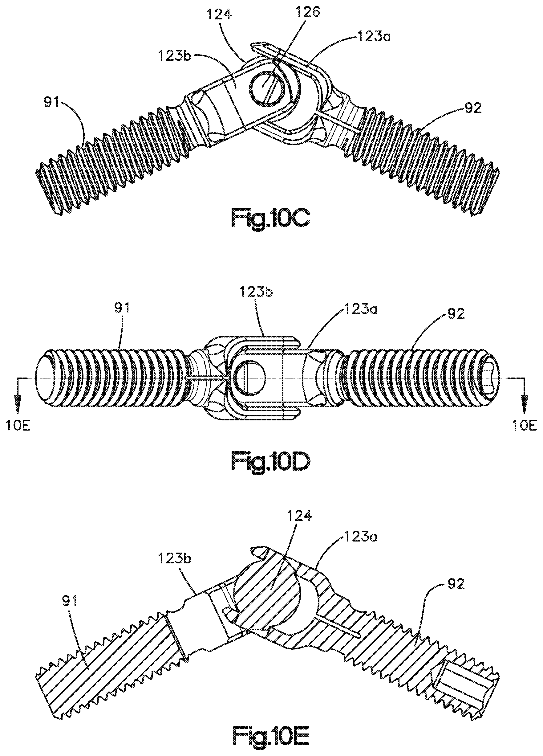
D00017

D00018
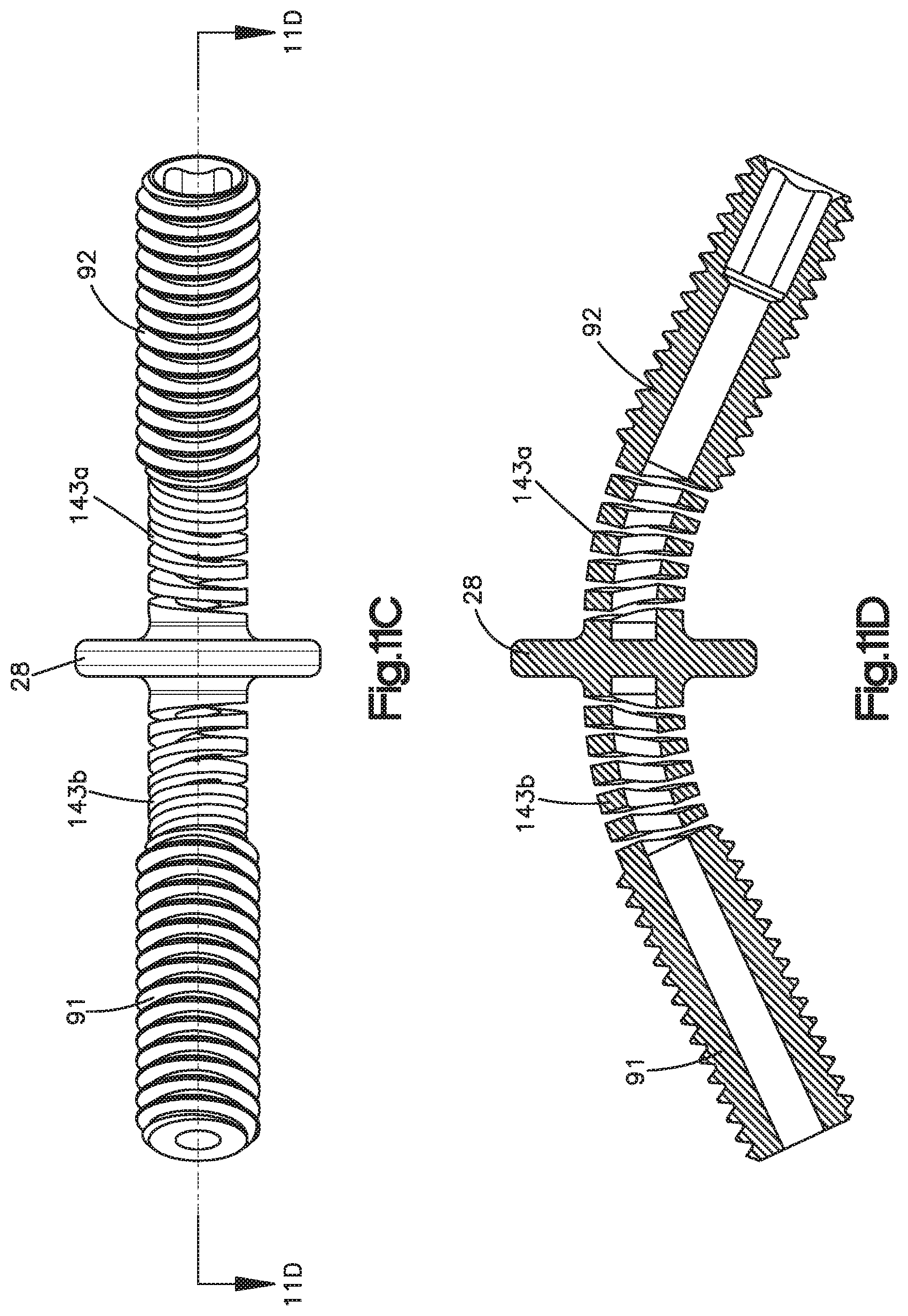
XML
uspto.report is an independent third-party trademark research tool that is not affiliated, endorsed, or sponsored by the United States Patent and Trademark Office (USPTO) or any other governmental organization. The information provided by uspto.report is based on publicly available data at the time of writing and is intended for informational purposes only.
While we strive to provide accurate and up-to-date information, we do not guarantee the accuracy, completeness, reliability, or suitability of the information displayed on this site. The use of this site is at your own risk. Any reliance you place on such information is therefore strictly at your own risk.
All official trademark data, including owner information, should be verified by visiting the official USPTO website at www.uspto.gov. This site is not intended to replace professional legal advice and should not be used as a substitute for consulting with a legal professional who is knowledgeable about trademark law.