System and methods for tracking robotically controlled medical instruments
Wong , et al. Ja
U.S. patent number 10,531,864 [Application Number 16/165,377] was granted by the patent office on 2020-01-14 for system and methods for tracking robotically controlled medical instruments. This patent grant is currently assigned to Auris Health, Inc.. The grantee listed for this patent is AURIS HEALTH, INC.. Invention is credited to Jason Hsu, Kiran Murthy, June Park, Neal A. Tanner, Sean Walker, Serena H. Wong.


| United States Patent | 10,531,864 |
| Wong , et al. | January 14, 2020 |
System and methods for tracking robotically controlled medical instruments
Abstract
Systems and methods are described herein for tracking an elongate instrument or other medical instrument in an image.
| Inventors: | Wong; Serena H. (Mountain View, CA), Walker; Sean (Mountain View, CA), Hsu; Jason (Mountain View, CA), Park; June (San Jose, CA), Tanner; Neal A. (Burnet, TX), Murthy; Kiran (Sunnyvale, CA) | ||||||||||
|---|---|---|---|---|---|---|---|---|---|---|---|
| Applicant: |
|
||||||||||
| Assignee: | Auris Health, Inc. (Redwood
City, CA) |
||||||||||
| Family ID: | 51531001 | ||||||||||
| Appl. No.: | 16/165,377 | ||||||||||
| Filed: | October 19, 2018 |
Prior Publication Data
| Document Identifier | Publication Date | |
|---|---|---|
| US 20190117203 A1 | Apr 25, 2019 | |
Related U.S. Patent Documents
| Application Number | Filing Date | Patent Number | Issue Date | ||
|---|---|---|---|---|---|
| 15649522 | Jul 13, 2017 | 10130345 | |||
| 14663021 | Jul 18, 2017 | 9710921 | |||
| 13835698 | Apr 21, 2015 | 9014851 | |||
| Current U.S. Class: | 1/1 |
| Current CPC Class: | G06T 7/248 (20170101); A61B 90/39 (20160201); A61B 34/37 (20160201); A61B 17/00 (20130101); A61B 34/25 (20160201); A61B 34/30 (20160201); A61B 2034/301 (20160201); A61B 2034/105 (20160201); A61B 2034/2061 (20160201); A61B 2090/3782 (20160201); A61B 2090/3735 (20160201); A61B 2017/00212 (20130101); G06T 2207/30004 (20130101); A61B 2034/2059 (20160201); A61B 2090/3966 (20160201) |
| Current International Class: | A61B 17/00 (20060101); A61B 34/20 (20160101); G06T 7/246 (20170101); A61B 34/10 (20160101); A61B 90/00 (20160101); A61B 34/37 (20160101); A61B 34/30 (20160101); A61B 34/00 (20160101) |
References Cited [Referenced By]
U.S. Patent Documents
| 4745908 | May 1988 | Wardle |
| 5273025 | December 1993 | Sakiyama et al. |
| 5398691 | March 1995 | Martin et al. |
| 5408409 | April 1995 | Glassman et al. |
| 5524180 | June 1996 | Wang et al. |
| 5526812 | June 1996 | Dumoulin et al. |
| 5550953 | August 1996 | Seraji |
| 5553611 | September 1996 | Budd et al. |
| 5558091 | September 1996 | Acker et al. |
| 5631973 | May 1997 | Green |
| 5636255 | June 1997 | Ellis |
| 5713946 | February 1998 | Ben-Haim |
| 5729129 | March 1998 | Acker |
| 5749362 | May 1998 | Funda et al. |
| 5831614 | November 1998 | Tognazzini et al. |
| 5859934 | January 1999 | Green |
| 5873822 | February 1999 | Ferre et al. |
| 5876325 | March 1999 | Mizuno et al. |
| 5902239 | May 1999 | Buurman |
| 5935075 | June 1999 | Casscells |
| 5920319 | July 1999 | Vining et al. |
| 5951475 | September 1999 | Gueziec et al. |
| 6016439 | January 2000 | Acker |
| 6019724 | February 2000 | Gronningsaeter et al. |
| 6038467 | March 2000 | De Bliek et al. |
| 6047080 | April 2000 | Chen |
| 6059718 | May 2000 | Taniguchi et al. |
| 6063095 | May 2000 | Wang et al. |
| 6167292 | December 2000 | Badano |
| 6203493 | March 2001 | Ben-Haim |
| 6226543 | May 2001 | Gilboa et al. |
| 6233476 | May 2001 | Strommer et al. |
| 6246784 | June 2001 | Summers |
| 6246898 | June 2001 | Vesely |
| 6253770 | July 2001 | Acker et al. |
| 6259806 | July 2001 | Green |
| 6272371 | August 2001 | Shlomo |
| 6424885 | July 2002 | Niemeyer et al. |
| 6425865 | July 2002 | Salcudean et al. |
| 6466198 | October 2002 | Feinstein |
| 6545760 | April 2003 | Froggatt et al. |
| 6553251 | April 2003 | Lahdesmaki |
| 6592520 | July 2003 | Peszynski |
| 6593884 | July 2003 | Gilboa et al. |
| 6665554 | December 2003 | Charles |
| 6690964 | February 2004 | Beiger et al. |
| 6711429 | March 2004 | Gilboa et al. |
| 6726675 | April 2004 | Beyar |
| 6782287 | August 2004 | Grzeszczuk et al. |
| 6892090 | May 2005 | Verard et al. |
| 6926709 | August 2005 | Beiger et al. |
| 6994094 | February 2006 | Schwartz |
| 6996430 | February 2006 | Gilboa et al. |
| 7155315 | December 2006 | Niemeyer et al. |
| 7180976 | February 2007 | Wink |
| 7386339 | June 2008 | Strommer et al. |
| 7756563 | July 2010 | Higgins |
| 7850642 | December 2010 | Moll et al. |
| 8050523 | November 2011 | Younge et al. |
| 8190238 | May 2012 | Moll et al. |
| 8287522 | October 2012 | Moses et al. |
| 8290571 | October 2012 | Younge et al. |
| 8298135 | October 2012 | Ito et al. |
| 8317746 | November 2012 | Sewell et al. |
| 8394054 | March 2013 | Wallace et al. |
| 8460236 | June 2013 | Roelle et al. |
| 8515215 | August 2013 | Younge et al. |
| 8600551 | December 2013 | Itkowitz et al. |
| 8657781 | February 2014 | Sewell et al. |
| 8672837 | March 2014 | Roelle et al. |
| 8705903 | April 2014 | Younge et al. |
| 8811777 | August 2014 | Younge et al. |
| 8818143 | August 2014 | Younge et al. |
| 8821376 | September 2014 | Tolkowsky |
| 8864655 | October 2014 | Ramamurthy et al. |
| 8894610 | November 2014 | MacNamara et al. |
| 8929631 | January 2015 | Pfister et al. |
| 9014851 | April 2015 | Wong et al. |
| 9039685 | May 2015 | Larkin et al. |
| 9057600 | June 2015 | Walker et al. |
| 9138129 | September 2015 | Diolaiti |
| 9138166 | September 2015 | Wong et al. |
| 9173713 | November 2015 | Hart et al. |
| 9183354 | November 2015 | Baker et al. |
| 9186046 | November 2015 | Ramamurthy et al. |
| 9186047 | November 2015 | Ramamurthy et al. |
| 9254123 | February 2016 | Alvarez et al. |
| 9271663 | March 2016 | Walker et al. |
| 9272416 | March 2016 | Hourtash et al. |
| 9283046 | March 2016 | Walker et al. |
| 9289578 | March 2016 | Walker et al. |
| 9404734 | August 2016 | Ramamurthy et al. |
| 9441954 | September 2016 | Ramamurthy et al. |
| 9459087 | October 2016 | Dunbar |
| 9498291 | November 2016 | Balaji et al. |
| 9498601 | November 2016 | Tanner et al. |
| 9500472 | November 2016 | Ramamurthy et al. |
| 9500473 | November 2016 | Ramamurthy et al. |
| 9504604 | November 2016 | Alvarez |
| 9532840 | January 2017 | Wong et al. |
| 9561083 | February 2017 | Yu et al. |
| 9566414 | February 2017 | Wong et al. |
| 9622827 | April 2017 | Yu et al. |
| 9629595 | April 2017 | Walker et al. |
| 9629682 | April 2017 | Wallace et al. |
| 9636184 | May 2017 | Lee et al. |
| 9710921 | July 2017 | Wong |
| 9713509 | July 2017 | Schuh et al. |
| 9726476 | August 2017 | Ramamurthy et al. |
| 9727963 | August 2017 | Mintz et al. |
| 9737371 | August 2017 | Romo et al. |
| 9737373 | August 2017 | Schuh |
| 9744335 | August 2017 | Jiang |
| 9763741 | September 2017 | Alvarez et al. |
| 9788910 | October 2017 | Schuh |
| 9818681 | November 2017 | Machida |
| 9827061 | November 2017 | Balaji et al. |
| 9844353 | December 2017 | Walker et al. |
| 9844412 | December 2017 | Bogusky et al. |
| 9867635 | January 2018 | Alvarez et al. |
| 9918681 | March 2018 | Wallace et al. |
| 9931025 | April 2018 | Graetzel et al. |
| 9949749 | April 2018 | Noonan et al. |
| 9955986 | May 2018 | Shah |
| 9962228 | May 2018 | Schuh et al. |
| 9980785 | May 2018 | Schuh |
| 9993313 | June 2018 | Schuh et al. |
| 10016900 | July 2018 | Meyer et al. |
| 10022192 | July 2018 | Ummalaneni |
| 10046140 | August 2018 | Kokish et al. |
| 10080576 | September 2018 | Romo et al. |
| 10130345 | November 2018 | Wong et al. |
| 10130427 | November 2018 | Tanner et al. |
| 10136950 | November 2018 | Schoenefeld |
| 10145747 | December 2018 | Lin et al. |
| 10159532 | December 2018 | Ummalaneni et al. |
| 10299870 | May 2019 | Connolly et al. |
| 2001/0039421 | November 2001 | Heilbrun |
| 2002/0077533 | June 2002 | Bieger et al. |
| 2002/0120188 | August 2002 | Brock et al. |
| 2003/0105603 | June 2003 | Hardesty |
| 2003/0125622 | July 2003 | Schweikard |
| 2003/0195664 | October 2003 | Nowlin et al. |
| 2004/0047044 | March 2004 | Dalton |
| 2004/0186349 | September 2004 | Ewers |
| 2004/0263535 | December 2004 | Birkenbach et al. |
| 2005/0027397 | February 2005 | Niemeyer |
| 2005/0033149 | February 2005 | Strommer et al. |
| 2005/0060006 | March 2005 | Pflueger |
| 2005/0085714 | April 2005 | Foley et al. |
| 2005/0143649 | June 2005 | Minai et al. |
| 2005/0143655 | June 2005 | Satoh |
| 2005/0171508 | August 2005 | Gilboa |
| 2005/0193451 | September 2005 | Quistgaard et al. |
| 2005/0267359 | December 2005 | Hussaini et al. |
| 2005/0272975 | December 2005 | McWeeney et al. |
| 2006/0004286 | January 2006 | Chang |
| 2006/0013523 | January 2006 | Childers et al. |
| 2006/0015096 | January 2006 | Hauck et al. |
| 2006/0025676 | February 2006 | Viswanathan et al. |
| 2006/0058643 | March 2006 | Florent |
| 2006/0076023 | April 2006 | Rapacki et al. |
| 2006/0089624 | April 2006 | Voegele et al. |
| 2006/0098851 | May 2006 | Shoham |
| 2006/0100610 | May 2006 | Wallace et al. |
| 2006/0173290 | August 2006 | Lavallee et al. |
| 2006/0184016 | August 2006 | Glossop |
| 2006/0209019 | September 2006 | Hu |
| 2006/0258935 | November 2006 | Pile-Spellman et al. |
| 2006/0258938 | November 2006 | Hoffman et al. |
| 2007/0013336 | January 2007 | Nowlin et al. |
| 2007/0015997 | January 2007 | Higgins et al. |
| 2007/0032826 | February 2007 | Schwartz |
| 2007/0055128 | March 2007 | Glossop |
| 2007/0060790 | March 2007 | Kuru et al. |
| 2007/0073136 | March 2007 | Metzger |
| 2007/0078334 | April 2007 | Scully et al. |
| 2007/0123748 | May 2007 | Meglan |
| 2007/0135803 | June 2007 | Belson |
| 2007/0135886 | June 2007 | Maschke |
| 2007/0208252 | September 2007 | Makower |
| 2007/0225559 | September 2007 | Clerc et al. |
| 2007/0253599 | November 2007 | White et al. |
| 2007/0265503 | November 2007 | Schlesinger et al. |
| 2007/0269001 | November 2007 | Maschke |
| 2007/0276180 | November 2007 | Greenburg et al. |
| 2007/0293721 | December 2007 | Gilboa |
| 2007/0299353 | December 2007 | Harlev et al. |
| 2008/0071140 | March 2008 | Gattani |
| 2008/0079421 | April 2008 | Jensen |
| 2008/0118118 | May 2008 | Berger |
| 2008/0123921 | May 2008 | Gielen et al. |
| 2008/0161681 | July 2008 | Hauck |
| 2008/0183064 | July 2008 | Chandonnet |
| 2008/0183068 | July 2008 | Carls et al. |
| 2008/0183188 | July 2008 | Carls et al. |
| 2008/0201016 | August 2008 | Finlay |
| 2008/0207997 | August 2008 | Higgins et al. |
| 2008/0212082 | September 2008 | Froggatt et al. |
| 2008/0218770 | September 2008 | Moll et al. |
| 2008/0243142 | October 2008 | Gildenberg |
| 2008/0287963 | November 2008 | Rogers et al. |
| 2008/0306490 | December 2008 | Lakin et al. |
| 2008/0312501 | December 2008 | Hasegawa et al. |
| 2009/0076476 | March 2009 | Barbagli et al. |
| 2009/0248036 | October 2009 | Hoffman et al. |
| 2009/0259230 | October 2009 | Khadem |
| 2009/0262109 | October 2009 | Markowitz et al. |
| 2009/0295797 | December 2009 | Sakaguchi |
| 2010/0019890 | January 2010 | Helmer et al. |
| 2010/0039506 | February 2010 | Sarvestani et al. |
| 2010/0041949 | February 2010 | Tolkowsky |
| 2010/0054536 | March 2010 | Huang |
| 2010/0113852 | May 2010 | Sydora |
| 2010/0114115 | May 2010 | Schlesinger et al. |
| 2010/0125284 | May 2010 | Tanner et al. |
| 2010/0161022 | June 2010 | Tolkowsky |
| 2010/0161129 | June 2010 | Costa et al. |
| 2010/0185087 | July 2010 | Nields et al. |
| 2010/0225209 | September 2010 | Goldberg |
| 2010/0228191 | September 2010 | Alvarez et al. |
| 2010/0240989 | September 2010 | Stoianovici |
| 2010/0280525 | November 2010 | Alvarez et al. |
| 2010/0290530 | November 2010 | Huang et al. |
| 2010/0292565 | November 2010 | Meyer |
| 2010/0298641 | November 2010 | Tanaka |
| 2010/0328455 | December 2010 | Nam et al. |
| 2010/0331856 | December 2010 | Carlson et al. |
| 2011/0054303 | March 2011 | Barrick |
| 2011/0234780 | September 2011 | Ito |
| 2011/0238082 | September 2011 | Wenderow |
| 2011/0245665 | October 2011 | Nentwick |
| 2011/0248987 | October 2011 | Mitchell |
| 2011/0249016 | October 2011 | Zhang |
| 2011/0276179 | November 2011 | Banks et al. |
| 2011/0295248 | December 2011 | Wallace et al. |
| 2011/0295267 | December 2011 | Tanner et al. |
| 2011/0295268 | December 2011 | Roelle et al. |
| 2011/0319910 | December 2011 | Roelle et al. |
| 2012/0046521 | February 2012 | Hunter et al. |
| 2012/0056986 | March 2012 | Popovic |
| 2012/0065481 | March 2012 | Hunter |
| 2012/0069167 | March 2012 | Liu et al. |
| 2012/0082351 | April 2012 | Higgins |
| 2012/0165656 | June 2012 | Montag |
| 2012/0209069 | August 2012 | Popovic |
| 2012/0215094 | August 2012 | Rahimian et al. |
| 2012/0219185 | August 2012 | Hu |
| 2012/0289783 | November 2012 | Duindam et al. |
| 2013/0060146 | March 2013 | Yang et al. |
| 2013/0085330 | April 2013 | Ramamurthy et al. |
| 2013/0085331 | April 2013 | Ramamurthy et al. |
| 2013/0085333 | April 2013 | Ramamurthy et al. |
| 2013/0090528 | April 2013 | Ramamurthy et al. |
| 2013/0090530 | April 2013 | Ramamurthy |
| 2013/0090552 | April 2013 | Ramamurthy et al. |
| 2013/0165945 | June 2013 | Roelle |
| 2013/0243153 | September 2013 | Sra |
| 2013/0246334 | September 2013 | Ahuja |
| 2013/0259315 | October 2013 | Angot et al. |
| 2013/0345718 | December 2013 | Crawford |
| 2014/0114180 | April 2014 | Jain |
| 2014/0142591 | May 2014 | Alvarez et al. |
| 2014/0148808 | May 2014 | Inkpen et al. |
| 2014/0180063 | June 2014 | Zhao |
| 2014/0243849 | August 2014 | Saglam |
| 2014/0257334 | September 2014 | Wong et al. |
| 2014/0257746 | September 2014 | Dunbar et al. |
| 2014/0264081 | September 2014 | Walker et al. |
| 2014/0275988 | September 2014 | Walker et al. |
| 2014/0276033 | September 2014 | Brannan |
| 2014/0276392 | September 2014 | Wong et al. |
| 2014/0276394 | September 2014 | Wong et al. |
| 2014/0276594 | September 2014 | Tanner et al. |
| 2014/0276646 | September 2014 | Wong et al. |
| 2014/0276934 | September 2014 | Balaji et al. |
| 2014/0276937 | September 2014 | Wong et al. |
| 2014/0276938 | September 2014 | Hsu et al. |
| 2014/0277747 | September 2014 | Walker et al. |
| 2014/0296655 | October 2014 | Akhbardeh et al. |
| 2014/0309527 | October 2014 | Namati et al. |
| 2014/0309649 | October 2014 | Alvarez et al. |
| 2014/0350391 | November 2014 | Prisco et al. |
| 2014/0357953 | December 2014 | Roelle et al. |
| 2014/0357984 | December 2014 | Wallace et al. |
| 2014/0364870 | December 2014 | Alvarez et al. |
| 2015/0051482 | February 2015 | Liu et al. |
| 2015/0051592 | February 2015 | Kintz |
| 2015/0054929 | February 2015 | Ito et al. |
| 2015/0073266 | March 2015 | Brannan |
| 2015/0101442 | April 2015 | Romo |
| 2015/0119638 | April 2015 | Yu et al. |
| 2015/0141808 | May 2015 | Elhawary |
| 2015/0141858 | May 2015 | Razavi |
| 2015/0142013 | May 2015 | Tanner et al. |
| 2015/0164594 | June 2015 | Romo et al. |
| 2015/0164596 | June 2015 | Romo |
| 2015/0223725 | August 2015 | Engel |
| 2015/0223765 | August 2015 | Chopra |
| 2015/0223897 | August 2015 | Kostrzewski et al. |
| 2015/0223902 | August 2015 | Walker et al. |
| 2015/0265368 | September 2015 | Chopra |
| 2015/0265807 | September 2015 | Park et al. |
| 2015/0275986 | October 2015 | Cooper |
| 2015/0287192 | October 2015 | Sasaki |
| 2015/0297133 | October 2015 | Jouanique-Dubuis et al. |
| 2015/0313503 | November 2015 | Seibel et al. |
| 2015/0314110 | November 2015 | Park |
| 2015/0327939 | November 2015 | Kokish et al. |
| 2015/0335480 | November 2015 | Alvarez et al. |
| 2015/0375399 | December 2015 | Chiu et al. |
| 2016/0000520 | January 2016 | Lachmanovich |
| 2016/0001038 | January 2016 | Romo et al. |
| 2016/0007881 | January 2016 | Wong et al. |
| 2016/0008033 | January 2016 | Hawkins et al. |
| 2016/0067009 | March 2016 | Ramamurthy et al. |
| 2016/0111192 | April 2016 | Suzara |
| 2016/0175059 | June 2016 | Walker et al. |
| 2016/0199134 | July 2016 | Brown et al. |
| 2016/0202053 | July 2016 | Walker et al. |
| 2016/0213432 | July 2016 | Flexman |
| 2016/0213884 | July 2016 | Park |
| 2016/0228032 | August 2016 | Walker et al. |
| 2016/0270865 | September 2016 | Landey et al. |
| 2016/0279394 | September 2016 | Moll et al. |
| 2016/0287279 | October 2016 | Bovay et al. |
| 2016/0287346 | October 2016 | Hyodo et al. |
| 2016/0296294 | October 2016 | Moll et al. |
| 2016/0314710 | October 2016 | Jarc |
| 2016/0360947 | December 2016 | Iida |
| 2016/0374541 | December 2016 | Agrawal et al. |
| 2016/0374590 | December 2016 | Wong et al. |
| 2017/0007337 | January 2017 | Dan |
| 2017/0055851 | March 2017 | Al-Ali |
| 2017/0065356 | March 2017 | Balaji et al. |
| 2017/0079725 | March 2017 | Hoffman |
| 2017/0079726 | March 2017 | Hoffman |
| 2017/0100084 | April 2017 | Walker et al. |
| 2017/0100199 | April 2017 | Yu et al. |
| 2017/0105803 | April 2017 | Wong et al. |
| 2017/0113019 | April 2017 | Wong et al. |
| 2017/0119413 | May 2017 | Romo |
| 2017/0119481 | May 2017 | Romo et al. |
| 2017/0119484 | May 2017 | Tanner et al. |
| 2017/0151027 | June 2017 | Walker et al. |
| 2017/0165011 | June 2017 | Bovay et al. |
| 2017/0172673 | June 2017 | Yu et al. |
| 2017/0202627 | July 2017 | Sramek et al. |
| 2017/0209073 | July 2017 | Sramek et al. |
| 2017/0209224 | July 2017 | Walker et al. |
| 2017/0215808 | August 2017 | Shimol et al. |
| 2017/0215969 | August 2017 | Zhai et al. |
| 2017/0238807 | August 2017 | Veritkov et al. |
| 2017/0258366 | September 2017 | Tupin |
| 2017/0290631 | October 2017 | Lee et al. |
| 2017/0296202 | October 2017 | Brown |
| 2017/0325896 | November 2017 | Donhowe |
| 2017/0333679 | November 2017 | Jiang |
| 2017/0340396 | November 2017 | Romo et al. |
| 2017/0348067 | December 2017 | Krimsky |
| 2017/0360508 | December 2017 | Germain et al. |
| 2017/0365055 | December 2017 | Mintz et al. |
| 2017/0367782 | December 2017 | Schuh et al. |
| 2018/0025666 | January 2018 | Ho et al. |
| 2018/0056044 | March 2018 | Choi et al. |
| 2018/0177383 | June 2018 | Noonan et al. |
| 2018/0177556 | June 2018 | Noonan et al. |
| 2018/0177561 | June 2018 | Mintz et al. |
| 2018/0184988 | July 2018 | Walker et al. |
| 2018/0214011 | August 2018 | Graetzel et al. |
| 2018/0217734 | August 2018 | Koenig et al. |
| 2018/0221038 | August 2018 | Noonan et al. |
| 2018/0221039 | August 2018 | Shah |
| 2018/0240237 | August 2018 | Donhowe et al. |
| 2018/0250083 | September 2018 | Schuh et al. |
| 2018/0271616 | September 2018 | Schuh et al. |
| 2018/0279852 | October 2018 | Rafii-Tari et al. |
| 2018/0280660 | October 2018 | Landey et al. |
| 2018/0289243 | October 2018 | Landey et al. |
| 2018/0289431 | October 2018 | Draper et al. |
| 2018/0308247 | October 2018 | Gupta |
| 2018/0325499 | November 2018 | Landey et al. |
| 2018/0326181 | November 2018 | Kokish et al. |
| 2018/0333044 | November 2018 | Jenkins |
| 2018/0360435 | December 2018 | Romo |
| 2018/0368920 | December 2018 | Ummalaneni |
| 2019/0000559 | January 2019 | Berman et al. |
| 2019/0000560 | January 2019 | Berman et al. |
| 2019/0000566 | January 2019 | Graetzel et al. |
| 2019/0000576 | January 2019 | Mintz et al. |
| 2019/0046814 | February 2019 | Senden et al. |
| 2019/0083183 | March 2019 | Moll et al. |
| 2019/0105776 | April 2019 | Ho et al. |
| 2019/0105785 | April 2019 | Meyer |
| 2019/0107454 | April 2019 | Lin |
| 2019/0110839 | April 2019 | Rafii-Tari et al. |
| 2019/0110843 | April 2019 | Ummalaneni et al. |
| 2019/0117176 | April 2019 | Walker et al. |
| 2019/0151148 | April 2019 | Alvarez et al. |
| 2019/0125164 | May 2019 | Roelle et al. |
| 2019/0167361 | June 2019 | Walker et al. |
| 2019/0167366 | June 2019 | Ummalaneni |
| 2019/0167367 | June 2019 | Walker et al. |
| 2019/0175009 | June 2019 | Mintz |
| 2019/0175062 | June 2019 | Rafii-Tari et al. |
| 2019/0175287 | June 2019 | Hill |
| 2019/0175799 | June 2019 | Hsu |
| 2019/0183585 | June 2019 | Rafii-Tari et al. |
| 2019/0183587 | June 2019 | Rafii-Tari et al. |
| 104540439 | Aug 2015 | CN | |||
| 106821498 | Jun 2017 | CN | |||
| 3 025 630 | Jun 2016 | EP | |||
| 2015-519131 | Jul 2015 | JP | |||
| 10-2014-0009359 | Jan 2014 | KR | |||
| WO 03/086190 | Oct 2003 | WO | |||
| WO 06/099056 | Sep 2006 | WO | |||
| WO 09/097461 | Jun 2007 | WO | |||
| WO 13/116140 | Aug 2013 | WO | |||
| WO 14/058838 | Apr 2014 | WO | |||
| WO 15/089013 | Jun 2015 | WO | |||
| WO 17/066108 | Apr 2017 | WO | |||
| WO 17/167754 | Oct 2017 | WO | |||
Other References
|
Ciuti et al., 2012, Intra-operative monocular 30 reconstruction for image-guided navigation in active locomotion capsule endoscopy. Biomedical Robotics and Biomechatronics (Biorob), 4th IEEE Ras & Embs International Conference on IEEE. cited by applicant . Fallavollita et al., 2010, Acquiring multiview C-arm images to assist cardiac ablation procedures, EURASIP Journal on Image and Video Processing, vol. 2010, Article ID 871408, pp. 1-10. cited by applicant . Kumar et al., 2014, Stereoscopic visualization of laparoscope image using depth information from 3D model, Computer methods and programs in biomedicine 113(3):862-868. cited by applicant . Livatino et al., 2015, Stereoscopic visualization and 3-D technologies in medical endoscopic teleoperation, IEEE. cited by applicant . Luo et al., 2010, Modified hybrid bronchoscope tracking based on sequential monte carlo sampler: Dynamic phantom validation, Asian Conference on Computer Vision. Springer, Berlin, Heidelberg. cited by applicant . Mourgues et al., 2002, Flexible calibration of actuated stereoscopic endoscope for overlay inrobot assisted surgery, International Conference on Medical Image Computing and Computer-Assisted Intervention. Springer, Berlin, Heidelberg. cited by applicant . Nadeem et al., 2016, Depth Reconstruction and Computer-Aided Polyp Detection in Optical Colonoscopy Video Frames, arXiv preprint arXiv:1609.01329. cited by applicant . Point Cloud, Sep. 10, 2010, Wikipedia, 2 pp. cited by applicant . Racadio et al., Dec. 2007, Live 3D guidance in the interventional radiology suite, AJR, 189:W357-W364. cited by applicant . Sato et al., 2016, Techniques of stapler-based navigational thoracoscopic segmentectomy using virtual assisted lung mapping (VAL-MAP), Journal of Thoracic Disease, 8(Suppl 9):S716. cited by applicant . Shen et al., 2015, Robust camera localisation with depth reconstruction for bronchoscopic navigation, International Journal of Computer Assisted Radiology and Surgery, 10(6):801-813. cited by applicant . Solheim et al., May 14, 2009, Navigated resection of giant intracranial meningiomas based on intraoperative 3D ultrasound, Acta Neurochir, 151:1143-1151. cited by applicant . Song et al., 2012, Autonomous and stable tracking of endoscope instrument tools with monocular camera, Advanced Intelligent Mechatronics (AIM), 2012 IEEE-ASME International Conference on, IEEE. cited by applicant . St. Jude Medical, EnSite Velocity Cardiac Mapping System, online, http:--www.sjmprofessional.com-Products-US-Mapping-and-Visualization-EnSi- - te-Velocity.aspx. cited by applicant . Verdaasdonk et al., Jan. 23, 2012, Effect of microsecond pulse length and tip shape on explosive bubble formation of 2.78 .mu.m Er,Cr;YSGG and 2.94 .mu.m Er:YAG laser, Proceedings of SPIE, vol. 8221, 12. cited by applicant . Yip et al., 2012, Tissue tracking and registration for image-guided surgery, IEEE transactions on medical imaging 31(11):2169-2182. cited by applicant . Zhou et al., 2010, Synthesis of stereoscopic views from monocular endoscopic videos, Computer Vision and Pattern Recognition Workshops (CVPRW), 2010 IEEE Computer Society Conference on IEEE. cited by applicant . Haigron et al., 2004, Depth-map-based scene analysis for activew navigation in virtual angioscopy, IEEE Transactions on Medical Imaging, 23(11):1380-1390. cited by applicant . Konen et al., 1998, The VN-project: endoscopic image processing for neurosurgery, Computer Aided Surgery, 3:1-6. cited by applicant . Mayo Clinic, Robotic Surgery, https://www.mayoclinic.org/tests-procedures/robotic-surgery/about/pac-203- 94974?p=1, downloaded from the internet on Jul. 12, 2018, 2 pp. cited by applicant . Shi et al., Sep. 14-18, 2014, Simultaneous catheter and environment modeling for trans-catheter aortic valve implantation, IEEE/RSJ International Conference on Intelligent Robots and Systems, pp. 2024-2029. cited by applicant . Vemuri et al., Dec. 2015, Inter-operative biopsy site relocations in endoluminal surgery, IEEE Transactions on Biomedical Engineering, Institute of Electrical and Electronics Engineers, <10.1109/TBME.2015.2503981>. <hal-01230752>. cited by applicant . Wilson et al., 2008, a buyer's guide to electromagnetic tracking systems for clinical applications, Proc. of SPCI, 6918:69182B-1 p. 6918B-11. cited by applicant. |
Primary Examiner: Vu; Kim Y
Assistant Examiner: Delaney; Molly
Attorney, Agent or Firm: Knobbe, Martens, Olson & Bear LLP
Parent Case Text
CROSS-REFERENCE TO RELATED APPLICATIONS
This application is a continuation of U.S. patent application Ser. No. 15/649,522, filed Jul. 13, 2017, which is a continuation of U.S. patent application Ser. No. 14/663,021, filed Mar. 19, 2015, which is a continuation of U.S. patent application Ser. No. 13/835,698, filed Mar. 15, 2013, entitled "SYSTEMS AND METHODS FOR TRACKING ROBOTICALLY CONTROLLED MEDICAL INSTRUMENTS," the contents of each of which are hereby incorporated in their entirety by reference.
Claims
The invention claimed is:
1. A method of registering a tool of a robotic medical system to a desired frame, the method comprising: tracking a position of the tool of the robotic medical system using one or more sensors coupled to the tool; tracking a position of a physical component of the robotic medical system using one or more sensors coupled to the physical component; comparing a tool reference frame to a physical component reference frame to generate a registration of the tool to the physical component; comparing the physical component reference frame to a visualization reference frame to generate a registration of the physical component to a visualization of the anatomy; and determining a location of the tool in the visualization of the anatomy based on the registration of the physical component to the visualization of the anatomy and the registration of the tool to the physical component.
2. The method of claim 1, wherein at least one of the one or more sensors coupled to the tool or the one or more sensors coupled to the physical component comprises an electromagnetic sensor.
3. The method of claim 1, wherein at least one of the one or more sensors of the tool or the one or more sensors of the physical component comprises a fiber sensor.
4. The method of claim 1, further comprising displaying the location of the tool in the visualization of the anatomy.
5. The method of claim 4, wherein displaying the location of the tool in the visualization of the anatomy comprises overlaying localization data related to the tool on the visualization of the anatomy.
6. The method of claim 1, wherein the visualization of the anatomy comprises a CT image.
7. The method of claim 1, wherein the visualization of the anatomy comprises a fluoroscopy image.
8. The method of claim 1, wherein the visualization of the anatomy is one of a pre-operative anatomical image or an intra-operative image.
9. The method of claim 1, wherein the physical component of the robotic medical system is a table.
10. The method of claim 1, wherein a location of the physical component with respect to a visualization system used to obtain the visualization of the anatomy is known.
11. The method of claim 1, wherein the tool is a catheter.
12. The method of claim 1, wherein the tool is a splayer.
13. A method of registering a tool of a robotic medical system to a desired frame, the method comprising: tracking a position of the tool of the robotic medical system using one or more sensors coupled to the tool; tracking a position of a physical component of the robotic medical system using one or more sensors coupled to the physical component; comparing a tool reference frame to a physical component reference frame to generate a registration of the tool to the physical component; comparing the physical component reference frame to a visualization reference frame to generate a registration of the physical component to a visualization of the anatomy; and displaying a location of the tool in the visualization of the anatomy based on the registration of the physical component to the visualization of the anatomy and the registration of the tool to the physical component.
14. The method of claim 13, wherein at least one of the one or more sensors coupled to the tool or the one or more sensors coupled to the physical component comprises an electromagnetic sensor.
15. The method of claim 13, wherein at least one of the one or more sensors of the tool or the one or more sensors of the physical component comprises a fiber sensor.
16. The method of claim 13, wherein displaying the location of the tool in the visualization of the anatomy comprises overlaying localization data related to the tool on the visualization of the anatomy.
17. The method of claim 13, wherein the visualization of the anatomy comprises a CT image.
18. The method of claim 13, wherein the visualization of the anatomy comprises a fluoroscopy image.
19. The method of claim 13, wherein the visualization of the anatomy is one of a pre-operative anatomical image or an intra-operative image.
20. The method of claim 13, wherein the physical component of the robotic medical system is a table.
21. The method of claim 13, wherein location of the physical component with respect to visualization system used to obtain the visualization of the anatomy is known.
22. The method of claim 13, wherein the tool is a catheter.
23. The method of claim 13, wherein the tool is a splayer.
Description
TECHNICAL FIELD
The disclosure relates generally to medical instruments, such as elongate steerable instruments for minimally-invasive intervention or diagnosis, and more particularly to methods, systems, and apparatus for controlling or tracking the location, position, orientation or shape of one or more parts of a medical instrument using registration techniques.
BACKGROUND
Currently known minimally invasive procedures for diagnosis and treatment of medical conditions use shapeable instruments, such as steerable devices, flexible catheters or more rigid arms or shafts, to approach and address various tissue structures within the body. For various reasons, it is highly valuable to be able to determine the 3-dimensional spatial position of portions of such shapeable instruments relative to other structures, such as the operating table, other instruments, or pertinent anatomical tissue structures. Such information can be used for a variety of reasons, including, but not limited to: improve device control; to improve mapping of the region; to adapt control system parameters (whether kinematic and/or solid mechanic parameters); to estimate, plan and/or control reaction forces of the device upon the anatomy; and/or to even monitor the system characteristics for determination of mechanical problems. Alternatively, or in combination, shape information can be useful to simply visualize the tool with respect to the anatomy or other regions whether real or virtual.
In many conventional systems, the catheter (or other shapeable instrument) is controlled in an open-loop manner, as described in U.S. patent Ser. No. 12/822,876, the contents of which are incorporated by reference in its entirety. However, at times the assumed motion of the catheter does not match the actual motion of the catheter. One such reason for this issue is the presence of unanticipated or unmodeled constraints imposed by the patient's anatomy.
Thus to perform certain desired applications, such as, for example, instinctive driving, shape feedback, and driving in a fluoroscopy view or a model, there exists a need for tool sensors to be properly registered to the patient in real time. Moreover, there remains a need to apply the information gained by spatial information or shape and applying this information to produce improved device control or improved modeling when directing a robotic or similar device. There also remains a need to apply such controls to medical procedures and equipment.
SUMMARY
A robotic system for manipulating a tool with respect to a target space is disclosed herein. The tool comprises a sensor coupled thereto. The system comprises a robotic drive system and a controller. The robotic drive system comprises at least one actuator and is configured to couple with the tool to position the tool with respect to the target space. The controller is configured to use a registration between a sensor frame and a target space frame such that the controller can direct the robotic drive system in the target space frame using the registration. In some exemplary arrangements, the controller is configured to combine a plurality of discrete registrations to produce a combined registration between the sensor frame and the target space frame.
Other and further exemplary configurations and advantages thereof will become apparent from the following detailed description when read in view of the accompanying figures.
BRIEF DESCRIPTION OF THE DRAWINGS
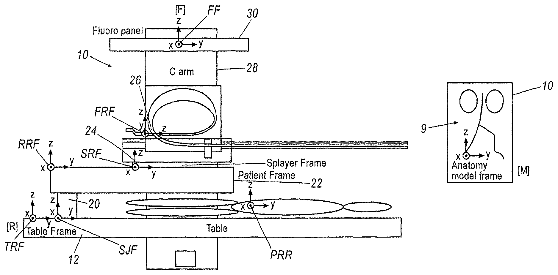
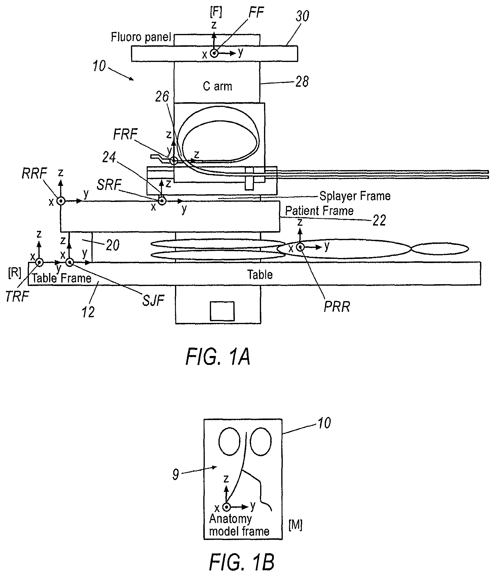
FIG. 1A illustrates a variation of a localization system in a typical operation room set up.
FIG. 1B illustrates a 3D Model frame.
FIG. 2 illustrates an exemplary robotic surgical system.
FIG. 3 is a schematic representation of a first registration technique of correlating a sensor reference frame to selective reference frames.
FIG. 4 is a flow chart that illustrates a method of transforming a reference frame for a sensor of a surgical tool into a target reference frame.
FIG. 5 is a flow chart that illustrates a method of transforming a reference frame associated with a tool into a target reference frame.
FIG. 6 is a flow chart that illustrates a method of transforming a reference frame associated with a tool into a target reference frame utilizing medical appliances.
FIG. 7 is a flow chart that illustrates a method of using a sensor to transform a reference frame associated with a tool into a target reference frame.
FIG. 8 is a schematic illustration of a method of using an intravascular imaging sensor coupled with a shape sensor to transform a reference frame associated with a tool into a target reference frame.
DETAILED DESCRIPTION
Various localization systems and methods for tracking an elongate instrument or tool, e.g., a robotically controlled elongate instrument, in real time, in a clinical or other environment, are described herein. The term "localization" is used in the art in reference to systems for determining and/or monitoring the position of objects, such as medical instruments or tools in a reference coordinate system. Various instruments are contemplated for use in the various systems described herein. In one exemplary arrangement, elongate instruments are contemplated, such as, e.g., a catheter or vascular catheter. The various methods and systems may include integrating or registering a localization system or a localization sensor coupled to a surgical tool, with an image. A fiber optic tracking or localization system is just one, non-limiting example of a system that allows for the tracking of a location, position and/or orientation of a localization sensor placed. Various other localization sensors may be utilized, e.g., electromagnetic sensors, and other sensors for detecting or controlling the movement of medical equipment. When the localization sensor is integrated into an image, it enhances the capabilities of an instrument control or tracking system by allowing a user or doctor to easily navigate the instrument through the complex anatomy without exposing the patient to excessive radiation over a prolonged period of time.
The localization data or tracking information of a localization sensor may be registered to the desired image or model to allow for navigation of an elongate instrument through the image or model to accurately represent movement of the elongate instrument within a patient. Registration is a process that requires relating a reference frame of a sensor to another reference frame of interest. If the positions, orientations or shapes of two or more objects are known in the same reference frame, then the actual positions, orientations or shapes of each object relative to each other may be ascertained. Thus, with this information, one can drive or manipulate one of the objects relative to the other objects.
In most interventional procedures, the reference frame of interest is the visualization frame. The reference frame is the frame that the doctor is viewing, such as a patient or a live 2D/3D image such fluoroscopy, ultrasound or others. Thus, the goal of registration is to determine the relationship of a frame of a sensor integrated into a tool or element in the surgical suite within the frame of reference of the patient, as represented in a 2D/3D image.
When the tool is registered to a 3D model, the user can drive and manipulate the tool in the 3D model. This technique provides an advantage in that there is no longer a need for live fluoroscopy and radiation during a procedure. The tool is localized to the 3D model and the position, shape and orientation of the tool is visible to the user. Since the tool position, shape and orientation is updated real time by a localization sensor, an image of the tool in the virtual representation of the 3D model will be updated as it is being advanced into the patient. The sensor is localized to the reference frame of the 3D model; therefore the orientation of a tip of the tool is known relative to the 3D model. This enables driving of the tool (such as a catheter) with 3 dimensional views of the anatomy and hence improves visualization and control during a surgical procedure.
However, many localization sensors are incremental measurement sensors, where the position and orientation of a particular point is calculated and dependent on the previously calculated orientation and positions/point spacings. Thus, the localization sensor operating in any medical system needs to be registered with a coordinate system, frame or image that is useful to an operator, such as the pre-operative 3D model or a fluoroscopic image. For incremental measurement sensors, such registration is challenging because the coordinate system or frame of the sensor is not always easily related to the coordinate system of interest (i.e., the pre-operative 3D model).
Moreover, the relationship between the sensor and the coordinate system of the interest may change over time during a procedure. For example, in one exemplary robotic system, a fiber optic sensor may have its reference frame based physically in a splayer for a catheter. Thus, as the splayer is robotically driven during a surgical procedure, the position and orientation of the bases of the fiber will change with respect to other reference frames.
In addition to changing positions of reference frames, the registration process often requires information about the imaging system providing the image, such as its physical dimensions and/or the details about the imaging techniques used to acquire a particular 3D model or other image. Due to the variability in equipment used in a clinical environment, in certain situations there may be no guarantee that such information will be available or easily obtainable to an outside party.
As such, various techniques to estimate system parameters and various registration techniques may help facilitate the clinical use of localization technology.
In certain variations, a method for tracking a robotically controlled elongate instrument in real time may include displaying an image of a patient's anatomy. A localization sensor may then be coupled to the robotically controlled instrument. The localization sensor may provide localization data of the sensor and/or instrument. Moreover, different sensors may be registered to specific tools, thereby enabling tool differentiation. The localization data from the localization sensor may be registered to the image. Registering may include transforming localization data generated by the localization sensor to the coordinate system or frame of the image such that localization data of the elongate instrument, to which the localization sensor is coupled, is overlaid on the image. The coordinate system of the localization sensor may be transformed or translated to the coordinate system of the image through one or more transformations, and optionally through other coordinate systems, to register the localization data to the image. As a result, a continuously or substantially continuously updated location of at least a portion of the elongate instrument is provided in the image of the anatomy of a patient, which allows for or facilitates robotic navigation or control of the elongate instrument through the anatomy e.g., through the vasculature of a patient.
The location, position and/or orientation of the localization sensor may be continuously tracked to allow for accurate manipulation of the elongate instrument in or through the anatomy of a patient. Various types of images may be utilized in the methods and systems described herein. For example, an image may be generated by CT or 2D or 3D fluoroscopy. An image may include a 3D or 2D anatomical model or a 2D or 3D fluoroscopic image or other types of images useful for visualizing an anatomy of a patient to perform various medical procedures.
When using a fluoroscopy image, an image intensifier may be utilized. Localization data from the localization sensor may be registered to a fluoroscopy coordinate system of a fluoroscopy image coupled to the image intensifier. In order to register the localization data from the localization sensor to the fluoroscopy image, various parameters may be ascertained or known. For example, such parameters may include: a distance from an X-ray source to the image intensifier, a distance from the source to a bed, a size of the image intensifier, and/or the axis of rotation of a C-arm of the fluoroscopy system.
In certain variations, localization data can be registered to a 3D anatomical model or a fluoroscopy image. The techniques used to perform the registration vary depending on the target. Where localization data is registered to a fluoroscopy image, the 2D nature of the fluoroscopy images may require that multiple images be taken at different angles before the registration process is complete.
FIG. 1A is a schematic of a typical operation room set up for a robotic surgical system. More specifically, a typical robotic surgical system 10 includes a table 12 upon which a patient 14 will be placed, a fluoroscopy system 16, and a surgical tool, such as a catheter 18 (best seen in FIG. 2). Attached to the table 12 is a setup joint arm 20 to which a remote catheter manipulator (RCM) 22 is operatively connected. A splayer 24 may be mounted to the RCM 22. A surgical tool, such as a catheter, is operatively connected to the splayer 24. A fiber sensor 26 may be operatively connected to the surgical tool. The fluoroscopy system 16 includes a C-arm 28. A fluoroscopy panel 30 is mounted to the C-arm 28. The C-arm is selectively moveable during the procedure to permit various images of the patient to be taken by the fluoroscopy panel 30.
Additional portions of the robotic surgical system 10 may be further seen in FIG. 2. More specifically, robotic surgical system 10 may further comprise an operator control station 31, which may be remotely positioned with respect to table 12. A communication link 32 transfers signals between the operator control station 31 and the RCM 22. The operator control station 31 includes a control console 34, a computer 36, a computer interface, such as a mouse, a visual display system 38 and a master input device 40. The master input device 40 may include, but is not limited to, a multi-degree of freedom device having multiple joints and associated encoders.
Each element of the robotic surgical system 10 positioned within the operating suite may define a separate reference frame to which sensors may be localized. More specifically, separate reference frames may be defined for each of elements of the robotic surgical system 10. Such reference frames may include the following: a table reference frame TRF for the table 12, a setup joint frame SJF for the setup joint 20, an RCM reference frame RRF for the remote catheter manipulator (RCM) 22, a splayer reference frame SRF, a fluoroscopy reference frame FF. Separate reference frames may also be defined for a patient-patient reference frame PRR, a reference frame FRF for a sensor disposed within a surgical tool, and a pre-operative 3D frame AMF (best seen in FIG. 1B).
To relate a coordinate frame of a fiber optic sensor of a tool to either a fluoroscopy frame FF, or a pre-operative 3D frame AMF, a variety registration techniques is proposed herein. Generally, the techniques proposed herein fall into several categories. A first category involves using image processing or vision techniques to relate a reference frame RFR of a fiber sensor directly to an image or 3D model. This technique may be accomplished manually by a user or done automatically using image processing techniques. Another category to coordinate the reference frame FRF of a fiber optic sensor involves using knowledge about hardware, and potentially other sensors and or position of the fiber. Further discussion of these techniques is set forth below.
Registration to Fluroscopy Coordinate Frame
Referring to FIG. 3, the first category of registration techniques will now be described. The first category relates the coordinate system of the sensor reference frame FRF to a fluoroscopy reference frame FF directly. This technique utilizes fluoroscopy images taken during the surgical procedure by the fluoroscopy system 30, in real-time.
More specifically, an exemplary registration process 200 is illustrated in the flow chart of FIG. 4. The process 200 begins by inserting a tool 202 into a patient. As described above, in one exemplary configuration, the tool 202 is a catheter 18, which may be inserted by an RCM 22. Next, in step 204 an intra-operative image is taken of the tool 18.
In one exemplary arrangement, the intra-operative image is a fluoroscopy image taken by fluoroscopy system 30. Next, distinctive elements of the tool are identified in the fluoroscopy image in step 206. In one exemplary configuration, the identification step 206 may be accomplished by instructing the user to select certain marked points of a catheter 18 in the fluoroscopy image at the work station 31. Examples of marked points include, but are not limited to, physical features of the catheter 18 such as the tip of the catheter 18, certain shapes and an articulation band. In other exemplary configurations, fluoroscopy markers may be disposed on the catheter.
Once the selected points are identified in the fluoroscopy image, in the next step 208, coordinates of the selected points of the catheter 18 may be compared to corresponding measured points of elements of the catheter. In one exemplary configuration, measured points from a tool sensor operatively connected to the tool 18 may be used. More specifically, in one exemplary configuration, the tool sensor is a fiber optic sensor. Information about the fiber optic sensor will be known in relation to the features on the catheter from an in-factory calibration. This comparison can be used to determine a transformation matrix that can be used to transform a reference frame FRF for a sensor disposed within the surgical tool to into the fluoroscopy reference frame FF. This transformation then localizes the tool relative to the intra-operative fluoroscopy image.
Once the fiber sensor of the tool has been registered or localized to the fluoroscopy image, the tool operator can now move or drive the tool to various, desired points visualized in the fluoroscopy image. Moreover, the computer 36 may be configured to track the marked points over time, such that an appropriate transformation may be updated.
In one exemplary configuration, the identifiable markers need not be on the portion of the tool that is inserted into the patient. For example, markers may be embedded on a splayer 24, which may allow for larger and more complex markers to provide enhanced registration capabilities.
As described above, in addition to utilizing fluoroscopy marked points, it is also contemplated that distinct shapes that may be visible under floursocopy may also be used. However, this technique will require some image segmentation.
With respect to the proposed technique of localizing a sensor reference frame FRF to the fluoroscopy reference frame FF, the localization sensor could serve to reduce the use of fluoroscopy during a procedure. More specifically, use of fluoroscopy will only be required when re-registration appears to be required from the captured image and the data obtained from the sensor if the accuracy of the registration needs to be improved at any point during the procedure.
In certain arrangements, it may be desirable to further register the tool to a 3D model reference frame AMF, as illustrated in FIG. 3. Registration to the 3D Model is discussed more fully below.
Registration Through Successive Physical Components
Another technique proposed to register a tool 18 to a desired reference frame involves the use of physical components of the medical system 10 and multiplying successive transformations. This proposed technique 300 is illustrated schematically in FIG. 5 and involves finding a transformation path from a tool reference frame such as a fiber sensor, splayer 24, or catheter 18, to the table 12, as in most surgical suite setups, the table location is generally known with respect to the fluoroscopy system 30. More specifically, registration technique 300 involves determining a tool reference frame 302 (where the tool reference frame may be defined as the sensor reference frame FRF, splayer reference frame SRF or a catheter reference frame) and correlating the tool reference frame to a table reference frame TRF in a second step 304, thereby registering the tool 18 to the table 12. Registering the tool 18 to the table 12 will serve to provide necessary information to permit registration to an additional target frame, such as a fluoroscopy reference frame FF, for example. Because the table 12 location is typically known with respect to a fluoroscopy system 30, once the tool 18 is registered to the table reference frame TRF, a comparison of set reference points of the table 12 with corresponding reference points in a fluoroscopy image may be used to determine a transformation matrix to transform the table reference frame TRF into the fluoroscopy reference frame FF. This transformation then localizes the tool relative to the intra-operative fluoroscopy image.
However, it is understood that the present disclosure does not require that the tool 18 be registered to the table 12. Indeed, it is expressly contemplated that registration of the tool 18 to other physical components within the surgical suite may also be utilized. This proposed technique requires the use of other sensors in addition to, or alternative to a fiber sensor, however. Exemplary configurations of registration through physical surgical suite components is are discussed in further detail below.
One exemplary method of performing registration through successive physical components is illustrated in the flow chart in FIG. 6. In this technique, the registration process 400 begins with the step 402 of determining the location of the setup joint 20 with respect to the table 12. Encoders on the RCM 22 and setup joint 20, with kinematic models may be used to determine the location of the setup joint 20 with respect to the table 12. More specifically, the encoders assist with determining the location of the RCM 22 with respect to the table 12. With the location value of the position that the setup joint 20 is fixed to the table 12, the location of the splayer carriage 24 carried by the RCM 22 with respect to the table 12 can be determined; i.e., the setup joint reference frame SJF is localized with the RCM reference frame RRF. Because information about the catheter will be known in relation to the splayer carriage 24 from an in-factory calibration, in step 404 of the registration process 400, a comparison of the splayer carriage 24 information with the can be used to determine a transformation matrix that can be used to transform the splayer carriage reference frame SRF to the table reference frame TRF. As described above, because the table 12 location is known with respect to the fluoroscopy system 30, in step 406 another transformation may be done from the table reference frame TRF to the fluoroscopy reference frame FF. This final transformation, i.e., from the table reference frame TRF to the fluoroscopy reference frame FF, then localizes the tool relative to the intra-operative fluoroscopy image.
In another exemplary method of performing registration through successive physical components, inertial sensors on the RCM 22, coupled with the information about the initial position of the RCM 22 on the table 12, may be used to assist in localizing the catheter splayer reference frame SRF to the table reference frame TRF. More specifically, once the RCM 22 is localized to the table reference frame TRF, the catheter splayer reference frame SRF may be localized to the table reference frame TRF, as the position of the catheter splayer 24 with respect to the RCM 22 will be known from in-factory calibration.
Yet another exemplary method 500 of performing registration through physical components is illustrated in FIG. 7. The method 500 uses a second fiber optic sensor. In a first step 502, one end of the fiber optic sensor is fixed to the table 12. Next, in step 504, the other end of the sensor is fixed to the splayer 24 in a known orientation/position. In this technique, a position and orientation transformation between the tip and base of the fiber sensor may be determined, thereby localizing the catheter splayer reference frame SRF to the table reference frame TRF in step 506. However, it is understood that the initial position of the fix point at the table must be known. Once the catheter splayer reference frame SRF is localized to the table reference frame TRF, because the table 12 location is known with respect to the fluoroscopy system 30, in step 508 another transformation may be done from the table reference frame TRF to the fluoroscopy reference frame FF. This final transformation, i.e., from the table reference frame TRF to the fluoroscopy reference frame FF, then localizes the tool relative to the intra-operative fluoroscopy image.
A further exemplary method of performing registration of a surgical tool to a physical component includes using electromagnetic sensors to track the location of the splayer 24 with respect to an electromagnetic sensor at a known location on the table 12. In using this technique, because the tool location is calibrated to the splayer 24 in the factory, once the splayer 24 is localized to the table reference frame TRF, the tool may be localized to the fluoroscopy reference frame FF as the table 12 is known with respect to the fluoroscopy system 30.
In yet another exemplary method, instead of electromagnetic sensors, overhead cameras or other visualization techniques may be employed to track distinct features on the splayer 24 and the table 12 to determine the respective orientation and position with regard to each other.
A further technique may use the range sensors (such as, e.g., IR or ultrasound) to find the distance to several distinct and predetermined points on the table 12 and the splayer 24. Once the splayer 24 is localized to the table reference frame TRF, the tool may be localized to the fluoroscopy reference frame FF as the table 12 is known with respect to the fluoroscopy system 30.
All of the above techniques serve to register the tool to a physical component within the surgical suite, such as, for example, the table 12. Some of the above techniques require the RCM 22 and setup joint 20 to be registered to the table 12. That pre-registration step may be achieved by using some known feature on the table 12 that the setup joint 20 may reference. In another exemplary configuration, the tip of a sensor equipped tool may be used to touch or register the known feature on the table 12 to locate the table 12 with respect to other equipment within the surgical suite.
The kinematics of the RCM 22 can also be calculated by holding the tip of a fiber optic equipped tool in an arbitrary fixed location and cycling through the various axes of the RCM 22. By keeping the tip in a fixed location, the relative changes to the fiber origin can be observed, and thus the kinematics of the system can be determined and localized to the table 12. Once localized to the table reference frame TRF, the tool may then be localized to the fluoroscopy reference frame FF, as discussed above.
In addition to adding the sensors discussed in the above techniques, additional modifications may be made to the location of the fiber base to facilitate registering the fiber sensor to the physical structure within the suite, such as, for example, the table 12. For example, one modification is to extend the length of a fiber in the catheter so that the origin/base can be extended out of the splayer 24 and attached to a fixture having a known location on the table 12. Once localized to the table reference frame TRF, the tool may then be localized to the fluoroscopy reference frame FF, as discussed above.
Registration to a 3D Model
Registration of the tool to a 3D Model is also contemplated in this disclosure. Such registration may be performed directly from the fiber sensor reference frame FRF to the 3D Model frame AMF. In one exemplary technique, the operator is utilized. When the tool (such as the catheter) is inserted into the patient, tortuosity can be visualized from the fiber sensor data, as well as on the pre-operative 3D Model. To register the tool in the 3D Model, the operator may translate and rotate the 3D Model so that distinct images and/or features in the tortuosity match or line up with the shape of the fibers. However, in using this technique, every time the patient moves, the tool should be re-registered.
In another exemplary arrangement, rather than have an operator manually match features in the tortuosity, in one technique, a computer algorithm such as automated geometric search or mathematical optimization techniques that segments the model and matches the model and tool shape dynamically may also be used to match various shapes or features from the fiber sensor to the 3D preoperative Model. However, if the patient moves, even slightly, the 3D Model could be mis-registered. Thus, the algorithms may be used to re-register the tool automatically or the user could use an input device, such as a track ball or mouse to move the 3D Model manually.
Another proposed technique may be used to register the fiber sensor to the 3D Model through the fluoroscopy image, as illustrated in FIG. 3. In this technique, any of the above described techniques for registering the surgical tool 12 to the fluoroscopy reference frame FF may be utilized. To register the fluoroscopy reference frame FF to the 3D Model reference frame AMF, in one exemplary configuration, specific anatomical landmarks may be used to provide recognizable reference points. The only requirement for this approach is to have an anatomical landmark that is recognizable in both the fluoroscopy reference frame FF, as well as the pre-operative 3D Model reference frame AMF. Once the recognizable point is identified in the fluoroscopy image, the 3D Model may then by rotated by the operator to line up the recognized points in the fluoroscopy images with the 3D Model images. This action serves to register the fluoroscopy reference frame FF to the frame of the 3D Model AMF. As the tool has previously been localized to the fluoroscopy reference plane FF, so now once the fluoroscopy reference plane FF is so registered, the tool's location within the patient's anatomy may be determined with reference to the 3D Model. Thus, the tool is localized to the 3D Model. In one exemplary configuration, a visual representation to the tool, based on the transformation matrix, may be displayed on the 3D Model. In this manner, the tool operator may then navigate the tool through the 3D Model.
While certain of the above described techniques utilized distinct marked points of a tool, such as a medical catheter, to register the tool with the fluoroscopy image, it is also understood that registration of the tool may occur based on the location of the tool at the distinct anatomical landmarks. In other words, as the tip of the tool can be driven to a known anatomical location in the patient, the 3D Model may then be rotated by the user to overlay the known anatomical location in the 3D Model with the fluoroscopy image, in which the known anatomical location is visible. Such action will also serve to register the tool with the 3D Model or localize the tool in the reference frame of the 3D model reference frame AMF.
In another exemplary configuration, instead of, or in addition to, having the user manually rotate the 3D Model to correspond with the fluoroscopy image to line up distinct landmarks visible in both the fluoroscopy image and the 3D Model, the computer 36 may be programmed to employ a suitable algorithm such as automated geometric search or mathematical optimization techniques configured to match a distinct shape measured by the fiber sensor with a corresponding shape in the 3D Model. In this manner, the tool may also be registered with the 3D Model. The accuracy of this method will depend on the size of vessel that the tool is in, and the degree of curvature of the tool. Accuracy will be improved if the tool is in a smaller vessel and will be worse if the tool is in larger vessels. This automated technique can also be used in conjunction with the manual techniques described above. For example, the computer may be programmed to do automatic registration and suggest a preferred registration but the user may do final adjustments of the model. Once the tool is localized in the 3D Model of the patient's anatomy, the user may then proceed to maneuver the tool in the 3D Model.
Another technique that may be utilized to register the tool to the 3D Model through fluoroscopy system 30 involves the use of radiopaque markers. More specifically, radiopaque markers can be fixed to the anatomy. However, these markers would need to be present during preoperative imaging when the 3D Model is created, and remain in the same location during intraoperative fluoroscopy imaging. With this technique, the position of these markers in the fluoroscopy reference frame FF can be used to correlate to the same markers in the 3D Model reference frame AMF, thereby registering the fiber sensor to the 3D Model reference frame AMF.
Another technique that may be utilized to register the surgical tool to a 3D Model utilizes intravascular imaging. This technique allows for 3D visualization of a surgical tool, such as, a catheter, in the anatomy, but without the use of fluoroscopic imaging. Such a technique can benefit both physicians and patients by improving the ease of tool navigation, as well as and reducing radiation exposure of personnel inside the operating room.
The registration technique 600 begins by utilizing a sensor 602 operatively coupled to the tool to sense a shape of the tool 604 while in the patient. This sensed shape is then mathematically correlated against features of the vascular model such as centerlines or walls in which a larger correlation value corresponds to a better match. The correlation can be performed in real-time on each shape or by batch processing a sequence of shapes. This proposed technique assumes that the tool will always follow a unique configuration through the vasculature, and thus, a global maximum for the correlation exists. However, the correlation may return many local maxima since the tool configuration may follow many different paths between fixed distal and proximal ends. Choosing an incorrect maximum introduces registration error. Furthermore, in some cases, the pre-operative 3D model may differ from the actual vasculature for a number of reasons, including, for example, patient motion or inaccuracies in pre-operative sensing. Such situations also may lead to registration error.
Recent advances in intravascular imaging technology have brought about sensors 604 that can provide information about the local structure of vessel walls 606. Such information may be used for shape registration and environmental mapping. Two examples of these sensors are intravascular ultrasound (NUS) probes, and optical coherence tomography (OCT). Intravascular ultrasound periodically produces a 2-D cross-sectional view of the blood vessel either to the sides of the catheter in standard NUS or to the front of a catheter in Forward-Facing IVUS. Optical Coherence Tomography periodically produces a local 3D view of the vessel into which the tool is inserted. The images produced by these technologies may be processed to provide an estimate of a curve or surface representing the vessel wall 606. The sensors 604 may also determine the location of the catheter's endpoint within the vascular cross-section. Use of the sensors coupled with the tool 602 to provide shape information coupled with information obtainable from sensors 604 configured to provide information about the vessel walls 606 can assist in defining the 3D shape of the blood vessel 608.
Once the shape of the vessel is defined or otherwise reconstructed using the combined sensor data, the shape can be mathematically correlated to the 3D model 610, thereby registering the tool to the 3D Model 612. In implementation, the 3D reconstruction and correlation steps may be combined into a single recursive filtering algorithm. A Bayesian filter (e.g. Kalman Filter (EKF), Unscented Kalman Filter (UKF), or Particle Filter) may be used to develop an estimate of the tool's position relative to the pre-op 3D model given both imaging and sensor 602 information. The filter's state is a set of points or a parametric curve representing the position and shape of the tool 602 with respect to the pre-op 3D model, as well as the velocity of this shape. For accurate registration, patient motion may also be taken into account. Thus, the filter's state may also contains warping parameters for the pre-op 3D model. These warping parameters may be evenly distributed, or may be selected based on the structure of the anatomy around the vasculature. The motion of the structure of the anatomy around the vasculature may be measured using visible light tracking technologies such as stereoscopic cameras, structured light tracking technologies, and/or other localization technologies attached to the patient skin.
The recursive filtering algorithm operates by predicting the motion of the tool in the 3D model, then performing an update of the filter hypothesis given new sensor measurements. At each time-step, a kinematic model of the catheter and control inputs such as current pull-wire tension and displacement may be used to perform the filter's motion update. The filter's measurement update may apply a correction to the tool registration and model warping parameters by comparing a predicted vessel wall with the sensed position and orientation of the vessel from the imaging and sensor measurements. The update effectively executes the correlation between 3-D sensor information and the 3D model. Performing these correlations repeatedly in a recursive filtering framework may provide a real-time catheter position estimate. Furthermore, the filter's parameters may be tuned such that differences between the measurements and the model over a small time constant (ms) will lead to changes in the catheter position estimate in order to filter out high-frequency sensor noise. Differences over a large time constant (seconds) may lead to changes in the model's warping parameters.
Thus, once the tool has been registered to the 3D model, the location of the tool within the 3D model may be determined, allowing an operator to drive the tool within the vasculature using the 3D model without requiring intra-operative fluoroscopy.
Sensors 604 may also be utilized to sense the environment around the tool. Thus, once the tool is registered to the 3D the model, this environmental information, such as, for example, vascular occlusions may be displayed at the correct position in the 3D Model.
More specifically, after tool registration, the intravascular imaging sensor 604 provides a mechanism to sense and display features of the environment surrounding the tool without the use of fluoroscopy. There are many ways to display this information. One non-limiting option is to simply provide a display of a real-time view of the imaging sensor's output alongside a view of the catheter's location in the 3D model or superimposed on top of the 3D model. Another option may be to analyze the intravascular image to detect environmental changes. For example, IVUS image processing techniques can be used to detect areas of plaque in the image. This information can be used to annotate the IVUS image in order to aleli the physician to environmental conditions. Since a combination of IVUS and sensor data 602 may provide 3D information on the structure of these plaque formations, the 3D pre-op model can also be annotated. In this way, the existing work that has used IVUS to perform vascular sensing may be leveraged by the combined IVUS and sensor system to provide a 3D view of the environment to the physician.
Each of the individual variations described and illustrated herein has discrete components and features which may be readily separated from or combined with the features of any of the other variations. Modifications may be made to adapt a particular situation, material, composition of matter, process, process act(s) or step(s) to the objective(s), spirit or scope of the present invention.
Methods recited herein may be carried out in any order of the recited events which is logically possible, as well as the recited order of events. Furthermore, where a range of values is provided, every intervening value between the upper and lower limit of that range and any other stated or intervening value in that stated range is encompassed within the invention. Also, any optional feature of the inventive variations described may be set forth and claimed independently, or in combination with any one or more of the features described herein.
All existing subject matter mentioned herein (e.g., publications, patents, patent applications and hardware) is incorporated by reference herein in its entirety except insofar as the subject matter may conflict with that of the present invention (in which case what is present herein shall prevail). The referenced items are provided solely for their disclosure prior to the filing date of the present application. Nothing herein is to be construed as an admission that the present invention is not entitled to antedate such material by virtue of prior invention.
Reference to a singular item, includes the possibility that there are plural of the same items present. More specifically, as used herein and in the appended claims, the singular forms "a," "an," "said" and "the" include plural referents unless the context clearly dictates otherwise. It is further noted that the claims may be drafted to exclude any optional element. As such, this statement is intended to serve as antecedent basis for use of such exclusive terminology as "solely," "only" and the like in connection with the recitation of claim elements, or use of a "negative" limitation. Unless defined otherwise, all technical and scientific terms used herein have the same meaning as commonly understood by one of ordinary skill in the art to which this invention belongs.
This disclosure is not intended to be limited to the scope of the particular forms set forth, but is intended to cover alternatives, modifications, and equivalents of the variations described herein. Further, the scope of the disclosure fully encompasses other variations that may become obvious to those skilled in the art in view of this disclosure. The scope of the present invention is limited only by the appended claims.
While multiple embodiments and variations of the many aspects of the invention have been disclosed and described herein, such disclosure is provided for purposes of illustration only. Many combinations and permutations of the disclosed system are useful in minimally invasive medical intervention and diagnosis, and the system is configured to be flexible. The foregoing illustrated and described embodiments of the invention are susceptible to various modifications and alternative forms, and it should be understood that the invention generally, as well as the specific embodiments described herein, are not limited to the particular forms or methods disclosed, but also cover all modifications, equivalents and alternatives falling within the scope of the appended claims. Further, the various features and aspects of the illustrated embodiments may be incorporated into other embodiments, even if no so described herein, as will be apparent to those skilled in the art.
* * * * *
References
D00000
D00001
D00002
D00003
D00004
XML
uspto.report is an independent third-party trademark research tool that is not affiliated, endorsed, or sponsored by the United States Patent and Trademark Office (USPTO) or any other governmental organization. The information provided by uspto.report is based on publicly available data at the time of writing and is intended for informational purposes only.
While we strive to provide accurate and up-to-date information, we do not guarantee the accuracy, completeness, reliability, or suitability of the information displayed on this site. The use of this site is at your own risk. Any reliance you place on such information is therefore strictly at your own risk.
All official trademark data, including owner information, should be verified by visiting the official USPTO website at www.uspto.gov. This site is not intended to replace professional legal advice and should not be used as a substitute for consulting with a legal professional who is knowledgeable about trademark law.