Catheter assembly including a multi-lumen configuration
Oborn , et al. Dec
U.S. patent number 10,518,064 [Application Number 15/442,608] was granted by the patent office on 2019-12-31 for catheter assembly including a multi-lumen configuration. This patent grant is currently assigned to C. R. Bard, Inc.. The grantee listed for this patent is C. R. Bard, Inc.. Invention is credited to William R Barron, Christian W. Crook, Ryan T. Moehle, Kelli D. Oborn.


View All Diagrams
| United States Patent | 10,518,064 |
| Oborn , et al. | December 31, 2019 |
Catheter assembly including a multi-lumen configuration
Abstract
A catheter assembly for use in accessing a vasculature of a patient is disclosed. In one embodiment, the catheter assembly includes a catheter body that includes a flattened oval outer surface and defines first and second lumens. The catheter body defines a distal tip region that includes a venous lateral opening that is in fluid communication with the first lumen and includes a distal-facing portion. The distal tip region further includes an arterial lateral opening that is in fluid communication with the second lumen, includes a distal-facing portion, and is substantially un-staggered with respect to the venous lateral opening. A distal end opening is in fluid communication with a power injectable third lumen. In another embodiment, the first and second lumens each generally include a reniform cross-sectional shape. In yet another embodiment, a dual-lumen catheter includes first and second lumens that each define a modified ellipse cross-sectional shape.
| Inventors: | Oborn; Kelli D. (Erda, UT), Moehle; Ryan T. (Salt Lake City, UT), Barron; William R (Riverton, UT), Crook; Christian W. (West Jordan, UT) | ||||||||||
|---|---|---|---|---|---|---|---|---|---|---|---|
| Applicant: |
|
||||||||||
| Assignee: | C. R. Bard, Inc. (Murray Hill,
NJ) |
||||||||||
| Family ID: | 52691581 | ||||||||||
| Appl. No.: | 15/442,608 | ||||||||||
| Filed: | February 24, 2017 |
Prior Publication Data
| Document Identifier | Publication Date | |
|---|---|---|
| US 20170165453 A1 | Jun 15, 2017 | |
Related U.S. Patent Documents
| Application Number | Filing Date | Patent Number | Issue Date | ||
|---|---|---|---|---|---|
| 14549941 | Feb 28, 2017 | 9579485 | |||
| 13329156 | Nov 25, 2014 | 8894601 | |||
| 12262820 | Jan 10, 2012 | 8092415 | |||
| 61907344 | Nov 21, 2013 | ||||
| 60984661 | Nov 1, 2007 | ||||
| Current U.S. Class: | 1/1 |
| Current CPC Class: | A61M 25/001 (20130101); A61M 25/0071 (20130101); A61M 1/3655 (20130101); A61M 25/0032 (20130101); B29C 48/12 (20190201); A61M 25/0069 (20130101); A61M 25/0068 (20130101); A61M 1/3653 (20130101); B29C 48/11 (20190201); A61M 25/0026 (20130101); A61M 25/09 (20130101); A61M 25/003 (20130101); A61M 25/0097 (20130101); B29C 48/0022 (20190201); A61M 25/007 (20130101); A61M 1/3661 (20140204); A61M 5/007 (20130101); A61M 25/02 (20130101); A61M 2025/0008 (20130101); A61M 2025/0073 (20130101); A61M 2025/0081 (20130101); B29C 2793/009 (20130101); B29L 2031/7542 (20130101); A61M 2025/0286 (20130101); A61M 2202/0021 (20130101); B29K 2075/00 (20130101); A61M 25/0009 (20130101); A61M 2025/0031 (20130101); A61M 2025/0037 (20130101) |
| Current International Class: | A61M 37/00 (20060101); B29C 48/00 (20190101); B29C 48/12 (20190101); B29C 48/11 (20190101); A61M 1/36 (20060101); A61M 25/00 (20060101); A61M 5/00 (20060101); A61M 25/09 (20060101); A61M 25/02 (20060101) |
References Cited [Referenced By]
U.S. Patent Documents
| 701075 | May 1902 | McCully |
| 1696018 | December 1928 | Scheliberg |
| 1856811 | May 1932 | Inaki |
| 2024982 | December 1935 | Scott |
| 2173527 | September 1939 | Agayoff |
| 2286462 | June 1942 | Chaffin |
| 2393002 | January 1946 | Smith |
| 2748769 | June 1956 | Huber |
| 2910981 | November 1959 | Wilson et al. |
| 3144868 | August 1964 | Jascalevich |
| 3176690 | April 1965 | H'Doubler |
| 3256885 | June 1966 | Higgins et al. |
| 3308822 | March 1967 | De Luca |
| 3416532 | December 1968 | Grossman |
| 3426759 | February 1969 | Smith |
| 3460255 | August 1969 | Hutson |
| D217795 | June 1970 | Spaven |
| 3612038 | October 1971 | Halligan |
| 3736939 | June 1973 | Taylor |
| 3805794 | April 1974 | Schlesinger |
| 3812851 | May 1974 | Rodriguez |
| 3848604 | November 1974 | Sackner |
| 3890977 | June 1975 | Wilson |
| 3929126 | December 1975 | Corsaut |
| 3935857 | February 1976 | Co |
| 3995623 | December 1976 | Blake et al. |
| 4068659 | January 1978 | Moorehead |
| 4072146 | February 1978 | Howes |
| 4072153 | February 1978 | Swartz |
| 4098275 | July 1978 | Consalvo |
| 4114625 | September 1978 | Onat |
| 4117836 | October 1978 | Erikson et al. |
| 4129129 | December 1978 | Amrine |
| 4134402 | January 1979 | Mahurkar |
| 4149535 | April 1979 | Volder |
| 4180068 | December 1979 | Jacobsen et al. |
| D254444 | March 1980 | Levine |
| 4248224 | February 1981 | Jones |
| 4276880 | July 1981 | Malmin |
| 4292976 | October 1981 | Banka |
| 4299228 | November 1981 | Peters |
| 4300550 | November 1981 | Gandi et al. |
| 4309994 | January 1982 | Grunwald |
| 4327722 | May 1982 | Groshong et al. |
| 4385631 | May 1983 | Uthmann |
| 4392855 | July 1983 | Oreopoulos et al. |
| 4403983 | September 1983 | Edelman et al. |
| 4405313 | September 1983 | Sisley et al. |
| 4406656 | September 1983 | Hattler et al. |
| D272651 | February 1984 | Mahurkar |
| 4431426 | February 1984 | Groshong et al. |
| 4432722 | February 1984 | Bohan, Jr. et al. |
| 4432752 | February 1984 | Marlon |
| 4445893 | May 1984 | Bodicky |
| 4451252 | May 1984 | Martin et al. |
| 4453928 | June 1984 | Steiger |
| 4465482 | August 1984 | Tittel et al. |
| 4490138 | December 1984 | Lipsky et al. |
| 4493696 | January 1985 | Uldall et al. |
| RE31873 | April 1985 | Howes |
| 4531933 | July 1985 | Norton et al. |
| 4543087 | September 1985 | Sommercorn et al. |
| 4545373 | October 1985 | Christoudias |
| 4549879 | October 1985 | Groshong et al. |
| 4557261 | December 1985 | Rugheimer et al. |
| 4568329 | February 1986 | Mahurkar |
| 4568338 | February 1986 | Todd |
| 4573476 | March 1986 | Ruiz |
| 4581012 | April 1986 | Brown et al. |
| 4583968 | April 1986 | Mahurkar |
| 4583986 | April 1986 | Lapidus |
| 4601697 | July 1986 | Mammolenti et al. |
| 4619643 | October 1986 | Bai |
| 4623327 | November 1986 | Mahurkar |
| 4626240 | December 1986 | Edelman et al. |
| 4642101 | February 1987 | Krolikowski et al. |
| 4643711 | February 1987 | Bates |
| 4666426 | May 1987 | Aigner et al. |
| 4668221 | May 1987 | Luther |
| 4670009 | June 1987 | Bullock |
| 4675004 | June 1987 | Hadford et al. |
| 4681122 | July 1987 | Winters et al. |
| 4681564 | July 1987 | Landreneau |
| 4681570 | July 1987 | Dalton |
| 4682978 | July 1987 | Martin et al. |
| 4687471 | August 1987 | Twardowski et al. |
| 4692141 | September 1987 | Mahurkar |
| 4694838 | September 1987 | Wijayarthna et al. |
| 4701159 | October 1987 | Brown et al. |
| 4702917 | October 1987 | Schindler |
| 4706671 | November 1987 | Weinrib |
| 4713171 | December 1987 | Polaschegg |
| 4717379 | January 1988 | Ekholmer et al. |
| 4735620 | April 1988 | Ruiz |
| 4737141 | April 1988 | Spits et al. |
| 4737152 | April 1988 | Alchas |
| 4738667 | April 1988 | Galloway |
| 4748808 | June 1988 | Hill |
| 4755176 | July 1988 | Patel |
| 4769016 | September 1988 | Labianca |
| 4770652 | September 1988 | Mahurkar |
| 4772268 | September 1988 | Bates |
| 4772269 | September 1988 | Twardowski et al. |
| 4776841 | October 1988 | Catalano |
| 4777951 | October 1988 | Cribier et al. |
| 4784638 | November 1988 | Ghajar et al. |
| 4790809 | December 1988 | Kuntz |
| 4795439 | January 1989 | Guest |
| 4801297 | January 1989 | Mueller |
| D300060 | February 1989 | Molgaard-Nielsen |
| 4804359 | February 1989 | Grunwald et al. |
| 4808155 | February 1989 | Mahurkar |
| 4808163 | February 1989 | Laub |
| 4809710 | March 1989 | Williamson |
| 4820265 | April 1989 | DeSatnick et al. |
| 4832687 | May 1989 | Smith, III |
| 4834709 | May 1989 | Banning et al. |
| 4842582 | June 1989 | Mahurkar |
| 4842592 | June 1989 | Caggiani et al. |
| 4846814 | July 1989 | Ruiz |
| 4863441 | September 1989 | Lindsay et al. |
| 4867742 | September 1989 | Calderon |
| 4892518 | January 1990 | Cupp et al. |
| 4894057 | January 1990 | Howes |
| 4895561 | January 1990 | Mahurkar |
| 4898591 | February 1990 | Jang et al. |
| 4906238 | March 1990 | Greenfeld et al. |
| 4925452 | May 1990 | Melinyshyn et al. |
| 4927418 | May 1990 | Dake et al. |
| 4935004 | June 1990 | Cruz |
| 4935010 | June 1990 | Cox et al. |
| 4935044 | June 1990 | Schoenpflug et al. |
| 4936826 | June 1990 | Amarasinghe |
| 4950232 | August 1990 | Ruzicka et al. |
| 4950259 | August 1990 | Geary et al. |
| 4951665 | August 1990 | Schneider |
| 4961729 | October 1990 | Vaillancourt |
| 4961731 | October 1990 | Bodicky et al. |
| 4961809 | October 1990 | Martin et al. |
| 4968307 | November 1990 | Dake et al. |
| 4969890 | November 1990 | Sugita et al. |
| 4981477 | January 1991 | Schon et al. |
| 4985014 | January 1991 | Orejola |
| 4990138 | February 1991 | Bacich et al. |
| 4994027 | February 1991 | Farrell |
| 4995865 | February 1991 | Gahara et al. |
| 5009636 | April 1991 | Wortley et al. |
| 5015230 | May 1991 | Martin et al. |
| 5016640 | May 1991 | Ruiz |
| 5021044 | June 1991 | Sharkawy |
| 5041101 | August 1991 | Seder et al. |
| 5041107 | August 1991 | Heil, Jr. |
| 5049138 | September 1991 | Chevalier et al. |
| 5053003 | October 1991 | Dadson et al. |
| 5053004 | October 1991 | Markel et al. |
| 5053023 | October 1991 | Martin |
| 5057073 | October 1991 | Martin |
| 5059170 | October 1991 | Cameron |
| 5059177 | October 1991 | Towne et al. |
| 5069673 | December 1991 | Shwab |
| 5074841 | December 1991 | Ademovic et al. |
| 5084013 | January 1992 | Takase et al. |
| 5098412 | March 1992 | Shiu et al. |
| 5100395 | March 1992 | Rosenberg et al. |
| 5102402 | April 1992 | Dror et al. |
| 5106368 | April 1992 | Uldall et al. |
| 5106376 | April 1992 | Mononen et al. |
| 5111829 | May 1992 | Alvarez de Toledo |
| 5112301 | May 1992 | Fenton, Jr. et al. |
| 5114423 | May 1992 | Kasprzyk et al. |
| 5117836 | June 1992 | Millar |
| 5120299 | June 1992 | Lombardi |
| 5120304 | June 1992 | Sasaki |
| 5122125 | June 1992 | Deuss et al. |
| 5125888 | June 1992 | Howard et al. |
| 5125904 | June 1992 | Lee |
| 5129891 | July 1992 | Young |
| 5135599 | August 1992 | Martin et al. |
| 5139486 | August 1992 | Moss |
| 5156592 | October 1992 | Martin et al. |
| 5163928 | November 1992 | Hobbs et al. |
| 5167623 | December 1992 | Cianci et al. |
| 5171216 | December 1992 | Dasse et al. |
| 5171227 | December 1992 | Twardowski et al. |
| 5178616 | January 1993 | Uemiya et al. |
| 5188592 | February 1993 | Hakki |
| 5188593 | February 1993 | Martin |
| 5190520 | March 1993 | Fenton, Jr. et al. |
| 5190529 | March 1993 | McCrory et al. |
| 5191898 | March 1993 | Millar |
| 5195962 | March 1993 | Martin et al. |
| 5197951 | March 1993 | Mahurkar |
| 5197973 | March 1993 | Pang et al. |
| 5197976 | March 1993 | Herweck et al. |
| 5201723 | April 1993 | Quinn |
| 5207648 | May 1993 | Gross |
| 5207650 | May 1993 | Martin |
| 5209723 | May 1993 | Twardowski et al. |
| 5209725 | May 1993 | Roth |
| 5209742 | May 1993 | Venema et al. |
| 5215527 | June 1993 | Beck et al. |
| 5221255 | June 1993 | Mahurkar et al. |
| 5221256 | June 1993 | Mahurkar |
| 5222949 | June 1993 | Kaldany |
| 5226880 | July 1993 | Martin et al. |
| 5234438 | August 1993 | Semrad |
| 5236016 | August 1993 | Vogelsang et al. |
| 5242398 | September 1993 | Knoll et al. |
| 5246430 | September 1993 | MacFarlane |
| 5250034 | October 1993 | Appling et al. |
| 5254084 | October 1993 | Geary |
| 5273527 | December 1993 | Schatz et al. |
| 5273534 | December 1993 | Knoepfler |
| 5279596 | January 1994 | Castaneda et al. |
| 5279599 | January 1994 | Wilk |
| 5306240 | April 1994 | Berry |
| 5312337 | May 1994 | Flaherty et al. |
| 5312357 | May 1994 | Buijs et al. |
| 5318517 | June 1994 | Reiman |
| 5322519 | June 1994 | Ash |
| 5324274 | June 1994 | Martin |
| 5330432 | July 1994 | Yoon |
| 5338308 | August 1994 | Wilk |
| 5342295 | August 1994 | Imran |
| 5342386 | August 1994 | Trotta |
| 5346471 | September 1994 | Raulerson |
| 5348536 | September 1994 | Young et al. |
| 5350358 | September 1994 | Martin |
| 5360397 | November 1994 | Pinchuk |
| 5360407 | November 1994 | Leonard et al. |
| 5364344 | November 1994 | Beattie et al. |
| 5374245 | December 1994 | Mahurkar |
| 5378230 | January 1995 | Mahurkar |
| 5380276 | January 1995 | Miller et al. |
| 5380290 | January 1995 | Makower et al. |
| 5382238 | January 1995 | Abrahamson et al. |
| 5389087 | February 1995 | Miraki |
| 5389090 | February 1995 | Fischell et al. |
| 5395316 | March 1995 | Martin et al. |
| 5399168 | March 1995 | Wadsworth, Jr. et al. |
| 5403291 | April 1995 | Abrahamson |
| 5405320 | April 1995 | Twardowski et al. |
| 5405341 | April 1995 | Martin |
| 5409463 | April 1995 | Thomas et al. |
| 5417668 | May 1995 | Setzer et al. |
| 5423768 | June 1995 | Folden et al. |
| 5431661 | July 1995 | Koch |
| 5451026 | September 1995 | Smith |
| 5451206 | September 1995 | Young |
| 5451233 | September 1995 | Yock |
| 5458570 | October 1995 | May, Jr. |
| 5458582 | October 1995 | Nakao |
| 5462533 | October 1995 | Daugherty |
| 5472417 | December 1995 | Martin et al. |
| 5472432 | December 1995 | Martin |
| 5476453 | December 1995 | Mehta |
| 5480380 | January 1996 | Martin |
| 5486159 | January 1996 | Mahurkar |
| 5489278 | February 1996 | Abrahamson |
| 5496292 | March 1996 | Burnham |
| 5496872 | March 1996 | Constancis et al. |
| 5505710 | April 1996 | Dorsey, III |
| 5507723 | April 1996 | Keshaviah |
| 5509897 | April 1996 | Twardowski et al. |
| 5509900 | April 1996 | Kirkman |
| 5509902 | April 1996 | Raulerson |
| 5542925 | August 1996 | Orth |
| 5545373 | August 1996 | Maziasz et al. |
| 5556390 | September 1996 | Hicks |
| 5556930 | September 1996 | Brehm et al. |
| 5558635 | September 1996 | Cannon |
| 5562609 | October 1996 | Brumbach |
| 5562696 | October 1996 | Nobles et al. |
| 5569182 | October 1996 | Twardowski et al. |
| 5569195 | October 1996 | Saab |
| 5571093 | November 1996 | Cruz et al. |
| 5584803 | December 1996 | Stevens et al. |
| 5599304 | February 1997 | Shaari |
| 5599328 | February 1997 | Stevens |
| 5607462 | March 1997 | Imran |
| 5624392 | April 1997 | Saab |
| 5624413 | April 1997 | Markel et al. |
| 5632729 | May 1997 | Cai et al. |
| 5637102 | June 1997 | Tolkoff et al. |
| 5642270 | June 1997 | Green et al. |
| 5655867 | August 1997 | Gysi et al. |
| 5662606 | September 1997 | Cimino et al. |
| 5665067 | September 1997 | Linder et al. |
| 5674237 | October 1997 | Ott |
| 5685867 | November 1997 | Twardowski et al. |
| 5686867 | November 1997 | Sutardja et al. |
| 5693030 | December 1997 | Lee et al. |
| 5695457 | December 1997 | St. Goar et al. |
| 5704915 | January 1998 | Melsky et al. |
| 5713849 | February 1998 | Bosma et al. |
| 5713853 | February 1998 | Clark et al. |
| 5717216 | February 1998 | McCoy et al. |
| 5718678 | February 1998 | Fleming, III |
| 5718692 | February 1998 | Schon et al. |
| 5720735 | February 1998 | Dorros |
| 5738649 | April 1998 | Macoviak |
| 5741329 | April 1998 | Agrawal et al. |
| 5743873 | April 1998 | Cai et al. |
| 5752939 | May 1998 | Makoto et al. |
| 5769796 | June 1998 | Palermo et al. |
| 5772643 | June 1998 | Howell et al. |
| 5776096 | July 1998 | Fields |
| 5776111 | July 1998 | Tesio |
| 5785686 | July 1998 | Runge |
| 5792094 | August 1998 | Stevens et al. |
| 5792123 | August 1998 | Ensminger |
| 5797869 | August 1998 | Martin et al. |
| 5800384 | September 1998 | Russell et al. |
| 5800414 | September 1998 | Cazal et al. |
| 5800516 | September 1998 | Fine et al. |
| 5807311 | September 1998 | Palestrant |
| 5807318 | September 1998 | St. Goar et al. |
| 5807329 | September 1998 | Gelman |
| 5809897 | September 1998 | Powell et al. |
| 5810789 | September 1998 | Powers et al. |
| 5814016 | September 1998 | Valley et al. |
| 5830184 | November 1998 | Basta |
| 5830196 | November 1998 | Hicks |
| 5833671 | November 1998 | Macoviak et al. |
| 5843048 | December 1998 | Gross |
| 5858009 | January 1999 | Jonkman |
| 5861010 | January 1999 | Boussignac et al. |
| 5868717 | February 1999 | Prosl |
| 5873865 | February 1999 | Horzewski et al. |
| 5876366 | March 1999 | Dykstra et al. |
| 5876426 | March 1999 | Kume et al. |
| 5882347 | March 1999 | Mouris-Laan et al. |
| 5891111 | April 1999 | Ismael et al. |
| 5904670 | May 1999 | Schreiner |
| 5911715 | June 1999 | Berg et al. |
| 5913848 | June 1999 | Luther et al. |
| 5916208 | June 1999 | Luther et al. |
| 5919160 | July 1999 | Sanfilippo, II |
| 5944732 | August 1999 | Raulerson et al. |
| 5947937 | September 1999 | Urrutia et al. |
| 5947953 | September 1999 | Ash et al. |
| 5957879 | September 1999 | Roberts et al. |
| 5957893 | September 1999 | Luther et al. |
| 5957912 | September 1999 | Heitzmann |
| 5961486 | October 1999 | Twardowski et al. |
| 5964796 | October 1999 | Imran |
| 5976103 | November 1999 | Martin |
| 5976120 | November 1999 | Chow et al. |
| 5980551 | November 1999 | Summers et al. |
| 5984908 | November 1999 | Davis et al. |
| 5989206 | November 1999 | Prosl et al. |
| 5989213 | November 1999 | Maginot |
| 6001079 | December 1999 | Pourchez |
| 6033382 | March 2000 | Basta |
| 6036654 | March 2000 | Quinn et al. |
| 6059771 | May 2000 | Balbierz et al. |
| 6074374 | June 2000 | Fulton |
| 6086555 | July 2000 | Eliasen et al. |
| 6086557 | July 2000 | Morejohn et al. |
| 6090096 | July 2000 | St. Goar et al. |
| 6099513 | August 2000 | Spehalski |
| 6103778 | August 2000 | Hyon et al. |
| 6106540 | August 2000 | White et al. |
| 6113572 | September 2000 | Gailey et al. |
| 6117117 | September 2000 | Mauch |
| 6120494 | September 2000 | Jonkman |
| 6126631 | October 2000 | Loggie |
| 6132425 | October 2000 | Gough |
| 6143013 | November 2000 | Samson et al. |
| 6146354 | November 2000 | Beil |
| 6146373 | November 2000 | Cragg et al. |
| 6152909 | November 2000 | Bagaoisan et al. |
| 6156016 | December 2000 | Maginot |
| 6161547 | December 2000 | Barbut |
| 6178356 | January 2001 | Chastain et al. |
| 6180059 | January 2001 | Divino, Jr. et al. |
| 6190349 | February 2001 | Ash et al. |
| 6190371 | February 2001 | Maginot et al. |
| 6193685 | February 2001 | Goodin |
| 6196996 | March 2001 | Teirstein |
| 6206849 | March 2001 | Martin et al. |
| 6210365 | April 2001 | Afzal |
| 6210380 | April 2001 | Mauch |
| 6217527 | April 2001 | Selmon et al. |
| 6224622 | May 2001 | Kotzev |
| 6238406 | May 2001 | Ellis et al. |
| 6264627 | July 2001 | Liska et al. |
| 6273879 | August 2001 | Keith et al. |
| 6280413 | August 2001 | Clark et al. |
| 6280423 | August 2001 | Davey et al. |
| 6287326 | September 2001 | Pecor |
| 6293927 | September 2001 | McGuckin, Jr. |
| 6293958 | September 2001 | Berry et al. |
| 6296631 | October 2001 | Chow |
| 6299631 | October 2001 | Shalaby |
| 6322551 | November 2001 | Brugger |
| 6328730 | December 2001 | Harkrider, Jr. |
| 6342120 | January 2002 | Basta |
| 6361529 | March 2002 | Goodin et al. |
| 6383172 | May 2002 | Barbut |
| 6394141 | May 2002 | Wages et al. |
| 6394142 | May 2002 | Woelfel et al. |
| 6409700 | June 2002 | Siegel, Jr. et al. |
| 6413228 | July 2002 | Hung et al. |
| 6428513 | August 2002 | Abrahamson |
| 6443922 | September 2002 | Roberts et al. |
| 6450988 | September 2002 | Bradshaw |
| 6453185 | September 2002 | O'Keefe |
| 6454997 | September 2002 | Divino, Jr. et al. |
| 6455608 | September 2002 | Jia et al. |
| 6463335 | October 2002 | Munch et al. |
| 6468287 | October 2002 | Baugh |
| 6473633 | October 2002 | Heil, Jr. et al. |
| 6475207 | November 2002 | Maginot et al. |
| 6475209 | November 2002 | Larson et al. |
| 6478789 | November 2002 | Spehalski et al. |
| 6482169 | November 2002 | Kuhle |
| 6533763 | March 2003 | Schneiter |
| 6565594 | May 2003 | Herweck et al. |
| 6576001 | June 2003 | Werneth et al. |
| 6582459 | June 2003 | Lau et al. |
| 6585705 | July 2003 | Maginot et al. |
| 6592565 | July 2003 | Twardowski |
| 6595966 | July 2003 | Davey et al. |
| 6620118 | September 2003 | Prosl et al. |
| 6638242 | October 2003 | Wilson et al. |
| 6659134 | December 2003 | Navis |
| 6682498 | January 2004 | Ross |
| 6682519 | January 2004 | Schon |
| 6691625 | February 2004 | Duncan |
| 6695832 | February 2004 | Schon et al. |
| 6702776 | March 2004 | Quinn |
| 6712797 | March 2004 | Southern, Jr. |
| 6712798 | March 2004 | Constantz |
| 6719717 | April 2004 | Johnson et al. |
| 6719749 | April 2004 | Schweikert et al. |
| 6723084 | April 2004 | Maginot et al. |
| 6723114 | April 2004 | Shalaby |
| 6730299 | May 2004 | Tayot et al. |
| 6752827 | June 2004 | Ross et al. |
| 6755851 | June 2004 | Noda et al. |
| 6758836 | July 2004 | Zawacki |
| 6786664 | September 2004 | Claramunt et al. |
| 6786884 | September 2004 | DeCant, Jr. et al. |
| 6796991 | September 2004 | Nardeo |
| 6797107 | September 2004 | Kotzey |
| 6808510 | October 2004 | DiFiore |
| 6814718 | November 2004 | McGuckin, Jr. et al. |
| 6819951 | November 2004 | Patel et al. |
| 6821287 | November 2004 | Jang |
| 6824554 | November 2004 | Jang |
| 6835452 | December 2004 | Hamerski |
| 6837864 | January 2005 | Bertolero et al. |
| 6852079 | February 2005 | Miyano |
| 6852097 | February 2005 | Fulton, III |
| 6858019 | February 2005 | McGuckin, Jr. et al. |
| 6872198 | March 2005 | Wilson et al. |
| 6878143 | April 2005 | Andersen |
| 6881211 | April 2005 | Schweikert et al. |
| 6884253 | April 2005 | McFarlane |
| 6911014 | June 2005 | Wentling et al. |
| 6913601 | July 2005 | St Goar et al. |
| 6916313 | July 2005 | Cunningham |
| 6921396 | July 2005 | Wilson et al. |
| 6921411 | July 2005 | Yock |
| 6934142 | August 2005 | Grosse et al. |
| 6966886 | November 2005 | Appling |
| 6969381 | November 2005 | Voorhees |
| 6979318 | December 2005 | McDonald et al. |
| 6991625 | January 2006 | Gately et al. |
| D515211 | February 2006 | Chesnin |
| 6997894 | February 2006 | Caresio |
| 7008395 | March 2006 | Loggie |
| 7011645 | March 2006 | McGuckin, Jr. et al. |
| 7018384 | March 2006 | Skakoon |
| 7029467 | April 2006 | Currier et al. |
| 7066914 | June 2006 | Andersen |
| 7066925 | June 2006 | Gately et al. |
| 7074213 | July 2006 | McGuckin, Jr. et al. |
| 7077829 | July 2006 | McGuckin, Jr. et al. |
| 7087053 | August 2006 | Vanney |
| 7090654 | August 2006 | Lotito et al. |
| 7108674 | September 2006 | Quinn |
| D530420 | October 2006 | Chesnin |
| 7128734 | October 2006 | Wilson et al. |
| 7130700 | October 2006 | Gardeski et al. |
| 7141035 | November 2006 | Haggstrom |
| RE39451 | December 2006 | Kuhle |
| 7182746 | February 2007 | Haarala et al. |
| 7300430 | November 2007 | Wilson et al. |
| 7322953 | January 2008 | Redinger |
| 7347852 | March 2008 | Hobbs et al. |
| 7381204 | June 2008 | Wilson et al. |
| 7393339 | July 2008 | Zawacki et al. |
| 7422571 | September 2008 | Schweikert et al. |
| 7465286 | December 2008 | Patterson et al. |
| 7485107 | February 2009 | DiFiore et al. |
| 7569029 | August 2009 | Clark |
| 7575563 | August 2009 | Appling |
| 7651482 | January 2010 | Harris |
| 7686823 | March 2010 | Pingleton et al. |
| 7798999 | September 2010 | Bailey et al. |
| 7972465 | July 2011 | Patterson et al. |
| 8021321 | September 2011 | Zawacki |
| 8066660 | November 2011 | Gregersen et al. |
| 8092415 | January 2012 | Moehle |
| 8100863 | January 2012 | Moehle et al. |
| 8152951 | April 2012 | Zawacki et al. |
| 8206371 | June 2012 | Nimkar et al. |
| 8292841 | October 2012 | Gregersen |
| 8500939 | August 2013 | Nimkar et al. |
| 8540661 | September 2013 | Gregersen |
| 8597275 | December 2013 | Nimkar et al. |
| 8696614 | April 2014 | Gregersen et al. |
| 8808227 | August 2014 | Zawacki et al. |
| 8894601 | November 2014 | Moehle et al. |
| 8992454 | March 2015 | Anand |
| 9174019 | November 2015 | Gregersen |
| 9233200 | January 2016 | Gregersen et al. |
| 9572956 | February 2017 | Nimkar et al. |
| 9579485 | February 2017 | Obom |
| 9610422 | April 2017 | Moehle et al. |
| 9669149 | June 2017 | Anand |
| 9782535 | October 2017 | Anand |
| 10105514 | October 2018 | Nimkar et al. |
| 10207043 | February 2019 | Gregersen |
| 10258732 | April 2019 | Gregersen et al. |
| 10258768 | April 2019 | Loesener et al. |
| 2001/0041857 | November 2001 | Sansoucy |
| 2001/0041873 | November 2001 | Dopper et al. |
| 2002/0013569 | January 2002 | Sterman et al. |
| 2002/0026156 | February 2002 | Quinn |
| 2002/0055724 | May 2002 | Hughes |
| 2002/0086047 | July 2002 | Mueller et al. |
| 2002/0087108 | July 2002 | Maginot et al. |
| 2002/0087145 | July 2002 | Ehwald et al. |
| 2002/0091362 | July 2002 | Maginot et al. |
| 2002/0091430 | July 2002 | Dobak et al. |
| 2002/0099326 | July 2002 | Wilson et al. |
| 2002/0099327 | July 2002 | Wilson et al. |
| 2002/0107506 | August 2002 | McGuckin et al. |
| 2002/0138031 | September 2002 | Ross |
| 2002/0169490 | November 2002 | Noda et al. |
| 2002/0173770 | November 2002 | Flory et al. |
| 2002/0177904 | November 2002 | Huxel et al. |
| 2003/0023198 | January 2003 | Twardowski |
| 2003/0032734 | February 2003 | Roby |
| 2003/0088213 | May 2003 | Schweikert et al. |
| 2003/0093027 | May 2003 | McGuckin et al. |
| 2003/0097091 | May 2003 | Hobbs et al. |
| 2003/0135147 | July 2003 | Rosenberg et al. |
| 2003/0144623 | July 2003 | Heath et al. |
| 2003/0149395 | August 2003 | Zawacki |
| 2003/0153898 | August 2003 | Schon et al. |
| 2003/0163145 | August 2003 | Raulerson |
| 2003/0187411 | October 2003 | Constantz |
| 2003/0204179 | October 2003 | Davey et al. |
| 2004/0039350 | February 2004 | McKittrick |
| 2004/0054321 | March 2004 | Schon et al. |
| 2004/0059314 | March 2004 | Schon et al. |
| 2004/0064086 | April 2004 | Gottlieb et al. |
| 2004/0065333 | April 2004 | Wilson et al. |
| 2004/0075198 | April 2004 | Schweikert et al. |
| 2004/0087892 | May 2004 | Cunningham |
| 2004/0092863 | May 2004 | Raulerson et al. |
| 2004/0097863 | May 2004 | Appling |
| 2004/0097903 | May 2004 | Raulerson |
| 2004/0122418 | June 2004 | Voorhees |
| 2004/0147903 | July 2004 | Latini |
| 2004/0167463 | August 2004 | Zawacki et al. |
| 2004/0171997 | September 2004 | Wilson et al. |
| 2004/0172003 | September 2004 | Wilson et al. |
| 2004/0176739 | September 2004 | Stephens et al. |
| 2004/0193102 | September 2004 | Haggstrom |
| 2004/0197301 | October 2004 | Zhao et al. |
| 2004/0210180 | October 2004 | Altman |
| 2004/0210187 | October 2004 | Zawacki |
| 2004/0210237 | October 2004 | Ross et al. |
| 2004/0220550 | November 2004 | Schryver |
| 2004/0230204 | November 2004 | Wortley et al. |
| 2004/0243095 | December 2004 | Nimkar et al. |
| 2004/0249337 | December 2004 | DiFiore |
| 2005/0003322 | January 2005 | Logan et al. |
| 2005/0004504 | January 2005 | Frye et al. |
| 2005/0013341 | January 2005 | Baghai |
| 2005/0019382 | January 2005 | Kummer et al. |
| 2005/0025641 | February 2005 | Shibata et al. |
| 2005/0027282 | February 2005 | Schweikert et al. |
| 2005/0027289 | February 2005 | Castellano et al. |
| 2005/0033222 | February 2005 | Haggstrom et al. |
| 2005/0033264 | February 2005 | Redinger |
| 2005/0054989 | March 2005 | McGuckin et al. |
| 2005/0055012 | March 2005 | Trerotola |
| 2005/0059925 | March 2005 | Maginot et al. |
| 2005/0070842 | March 2005 | Lotito et al. |
| 2005/0080398 | April 2005 | Markel et al. |
| 2005/0085765 | April 2005 | Voorhees |
| 2005/0096585 | May 2005 | Schon et al. |
| 2005/0113904 | May 2005 | Shank et al. |
| 2005/0131341 | June 2005 | McGuckin et al. |
| 2005/0171469 | August 2005 | Cunningham |
| 2005/0187535 | August 2005 | Wilson et al. |
| 2005/0209582 | September 2005 | Quinn et al. |
| 2005/0215977 | September 2005 | Uschold |
| 2005/0228339 | October 2005 | Clark |
| 2005/0245900 | November 2005 | Ash |
| 2005/0251190 | November 2005 | McFarlane |
| 2005/0256461 | November 2005 | DiFiore et al. |
| 2005/0261663 | November 2005 | Patterson et al. |
| 2005/0267400 | December 2005 | Haarala et al. |
| 2005/0277862 | December 2005 | Anand |
| 2005/0283111 | December 2005 | Maurice |
| 2005/0288623 | December 2005 | Hjalmarsson |
| 2005/0288706 | December 2005 | Widomski et al. |
| 2006/0004316 | January 2006 | Difiore et al. |
| 2006/0004325 | January 2006 | Hamatake et al. |
| 2006/0009783 | January 2006 | Rome et al. |
| 2006/0015072 | January 2006 | Raulerson |
| 2006/0015130 | January 2006 | Voorhees et al. |
| 2006/0030827 | February 2006 | Raulerson et al. |
| 2006/0047267 | March 2006 | Gately et al. |
| 2006/0047268 | March 2006 | Stephens |
| 2006/0058775 | March 2006 | Stevens et al. |
| 2006/0064072 | March 2006 | Gately et al. |
| 2006/0095062 | May 2006 | Stephens |
| 2006/0100572 | May 2006 | DiMatteo et al. |
| 2006/0111537 | May 2006 | Roby |
| 2006/0116629 | June 2006 | Tal et al. |
| 2006/0161100 | July 2006 | Hamboly |
| 2006/0184142 | August 2006 | Schon et al. |
| 2006/0189922 | August 2006 | Amarasinghe et al. |
| 2006/0200111 | September 2006 | Moehle et al. |
| 2006/0206094 | September 2006 | Chesnin et al. |
| 2006/0251612 | November 2006 | Kotzev et al. |
| 2006/0253063 | November 2006 | Schweikert |
| 2006/0271012 | November 2006 | Canaud et al. |
| 2007/0005003 | January 2007 | Patterson et al. |
| 2007/0019181 | January 2007 | Sinclair et al. |
| 2007/0066964 | March 2007 | Atkins |
| 2007/0078478 | April 2007 | Atkins et al. |
| 2007/0106206 | May 2007 | Appling |
| 2007/0129704 | June 2007 | O'Mahony et al. |
| 2007/0167925 | July 2007 | Jacqmein |
| 2007/0191810 | August 2007 | Kennedy |
| 2007/0225661 | September 2007 | Ash et al. |
| 2007/0225682 | September 2007 | Ash et al. |
| 2007/0282274 | December 2007 | Chesnin |
| 2008/0021417 | January 2008 | Zawacki et al. |
| 2008/0039774 | February 2008 | Zawacki et al. |
| 2008/0065029 | March 2008 | Racz |
| 2008/0082079 | April 2008 | Braga et al. |
| 2008/0082080 | April 2008 | Braga |
| 2008/0097409 | April 2008 | Stephens |
| 2008/0172012 | July 2008 | Hiniduma-Lokuge et al. |
| 2008/0214980 | September 2008 | Anand |
| 2008/0214992 | September 2008 | Haarala et al. |
| 2009/0112153 | April 2009 | Gregersen et al. |
| 2009/0118661 | May 2009 | Moehle et al. |
| 2009/0118701 | May 2009 | Nimkar et al. |
| 2009/0118707 | May 2009 | Schweikert et al. |
| 2009/0118755 | May 2009 | Maliglowka et al. |
| 2009/0138034 | May 2009 | Maliglowka et al. |
| 2009/0157051 | June 2009 | Appling et al. |
| 2009/0187141 | July 2009 | Lareau et al. |
| 2009/0192435 | July 2009 | Gregersen |
| 2009/0204052 | August 2009 | Nimkar et al. |
| 2009/0204079 | August 2009 | Nimkar et al. |
| 2009/0204083 | August 2009 | O'Donnell et al. |
| 2009/0205189 | August 2009 | Nimkar et al. |
| 2009/0209940 | August 2009 | Nimkar et al. |
| 2009/0292248 | November 2009 | Schon et al. |
| 2009/0312687 | December 2009 | DeFonzo et al. |
| 2010/0081986 | April 2010 | Matson et al. |
| 2010/0331780 | December 2010 | Bellisario et al. |
| 2011/0020418 | January 2011 | Bosley, Jr. et al. |
| 2011/0301522 | December 2011 | DeFonzo |
| 2012/0059304 | March 2012 | Gregersen et al. |
| 2012/0089070 | April 2012 | Moehle et al. |
| 2013/0018405 | January 2013 | Onishi et al. |
| 2013/0079752 | March 2013 | Gregersen |
| 2013/0253445 | September 2013 | Nimkar et al. |
| 2013/0261605 | October 2013 | Gregersen et al. |
| 2014/0018772 | January 2014 | Ash |
| 2014/0025042 | January 2014 | Gregersen |
| 2014/0088510 | March 2014 | Nimkar et al. |
| 2014/0228742 | August 2014 | Gregersen et al. |
| 2014/0276472 | September 2014 | VanderStek et al. |
| 2014/0276493 | September 2014 | Leung et al. |
| 2014/0277052 | September 2014 | Haselby et al. |
| 2014/0330220 | November 2014 | Zawacki et al. |
| 2014/0336687 | November 2014 | Iwase et al. |
| 2015/0073336 | March 2015 | Moehle et al. |
| 2015/0088100 | March 2015 | Oborn et al. |
| 2015/0335810 | November 2015 | Anand |
| 2017/0151418 | June 2017 | Nimkar et al. |
| 2019/0167888 | June 2019 | Gregersen |
| 2019/0240393 | August 2019 | Gregersen et al. |
| 2019/0240453 | August 2019 | Loesener et al. |
| 834211 | Feb 1976 | BE | |||
| 1150122 | Jul 1983 | CA | |||
| 2474351 | Aug 2003 | CA | |||
| 2788836 | Jun 2006 | CN | |||
| 101918067 | Dec 2010 | CN | |||
| 103170050 | Jun 2013 | CN | |||
| 101918066 | Jul 2013 | CN | |||
| 8815869 | Feb 1989 | DE | |||
| 9108132 | Sep 1991 | DE | |||
| 102005051211 | May 2007 | DE | |||
| 0030854 | Jun 1981 | EP | |||
| 0132344 | Jan 1985 | EP | |||
| 0301854 | Feb 1989 | EP | |||
| 0332366 | Sep 1989 | EP | |||
| 0386408 | Sep 1990 | EP | |||
| 0453234 | Oct 1991 | EP | |||
| 0476796 | Mar 1992 | EP | |||
| 0495263 | Jul 1992 | EP | |||
| 0650740 | May 1995 | EP | |||
| 0711574 | May 1996 | EP | |||
| 1471966 | Nov 2004 | EP | |||
| 1599247 | Nov 2005 | EP | |||
| 2305337 | Apr 2011 | EP | |||
| 1503469 | Mar 1978 | GB | |||
| 56-136569 | Oct 1981 | JP | |||
| 8-510935 | Nov 1996 | JP | |||
| 2001137350 | May 2001 | JP | |||
| 2008500081 | Jan 2008 | JP | |||
| 2011-502583 | Jan 2011 | JP | |||
| 4827377 | Nov 2011 | JP | |||
| 45923 | Nov 2004 | RU | |||
| 459237 | Feb 1975 | SU | |||
| 1991008132 | Jun 1991 | WO | |||
| 1993016741 | Sep 1993 | WO | |||
| 1993016752 | Sep 1993 | WO | |||
| 1997009086 | Mar 1997 | WO | |||
| 1997017102 | May 1997 | WO | |||
| 1997022374 | Jun 1997 | WO | |||
| 1997037699 | Oct 1997 | WO | |||
| 1999004844 | Feb 1999 | WO | |||
| 2000023137 | Apr 2000 | WO | |||
| 2002018004 | Mar 2002 | WO | |||
| 2002058776 | Aug 2002 | WO | |||
| 2002083223 | Oct 2002 | WO | |||
| 2003030960 | Apr 2003 | WO | |||
| 2003033049 | Apr 2003 | WO | |||
| 2003066148 | Aug 2003 | WO | |||
| 2004075962 | Sep 2004 | WO | |||
| 2004096334 | Nov 2004 | WO | |||
| 2004112876 | Dec 2004 | WO | |||
| 2005018712 | Mar 2005 | WO | |||
| 2005023336 | Mar 2005 | WO | |||
| 2005077449 | Aug 2005 | WO | |||
| 2005084741 | Sep 2005 | WO | |||
| 2005118039 | Dec 2005 | WO | |||
| 2006034877 | Apr 2006 | WO | |||
| 2008048183 | Apr 2008 | WO | |||
| WO-2008048183 | Apr 2008 | WO | |||
| 2009051967 | Apr 2009 | WO | |||
| 2009055332 | Apr 2009 | WO | |||
| 2009059220 | May 2009 | WO | |||
| 2015077560 | May 2015 | WO | |||
| 2016/011091 | Jan 2016 | WO | |||
Other References
|
Arrow Cannon II Plus Brochure, 2006. cited by applicant . Arrow International, Inc. et al v. Spire Biomedical, Inc., U.S. Dist Ct Dist MA CA No. 06-CV-11564-DPW, Declaration of Dr. Karim Valji (Jul. 17, 2008). cited by applicant . Arrow International, Inc. et al v. Spire Biomedical, Inc., U.S. Dist Ct Dist MA CA No. 06-CV-11564-DPW, Declaration of Kenneth Todd Cassidy (Jul. 16, 2008). cited by applicant . Arrow International, Inc. et al v. Spire Biomedical, Inc., U.S. Dist Ct Dist MA CA No. 06-CV-11564-DPW, Declaration of Rebecca R. Eisenberg in Opposition to Defendant's Motion for Partial Summary Judgment of Invalidity (Jun. 8, 2009). cited by applicant . Arrow International, Inc. et al v. Spire Biomedical, Inc., U.S. Dist Ct Dist MA CA No. 06-CV-11564-DPW, Memorandum of Law in Support of Defendant's Motion for Summary Judgment on Invalidity [Redacted Pursuant to Jun. 10, 2008 Order on Motion to Seal]. cited by applicant . Arrow International, Inc. et al v. Spire Biomedical, Inc., U.S. Dist Ct Dist MA CA No. 06-CV-11564-DPW, Memorandum of Law in Support of Defendants Motion for Summary Judgment on Invalidity Exhibit A (Jul. 10, 2009). cited by applicant . Arrow International, Inc. et al v. Spire Biomedical, Inc., U.S. Dist Ct Dist MA CA No. 06-CV-11564-DPW, Plaintiff's Memorandum in Opposition to Defendants Motion for Summary Judgement on Non-Infringement (Jul. 17, 2008). cited by applicant . Arrow International, Inc. et al. v. Spire Biomedical, Inc., U.S. Dist. Ct. Dist. MA CA No. 06-CV-11564-DPW, Defendant's Omnibus Statement of Material Facts in Support of its Motions for Summary Judgment (Jun. 10, 2008) [Redacted Pursuant to Jun. 10, 2008 Order on Motion to Seal]. cited by applicant . Bander, et al., Central Venous Angioaccess for Hemodialysis and Its Complications, Seminars in Dialysis, 1992, vol. 5, No. 2, pp. 121-128. cited by applicant . Baranowski, L., Central Venous Access Devices, Journal of Intravenous Nursing, 1993, vol. 16, No. 3, pp. 167-194. cited by applicant . BARD Access Systems Hickman.RTM., Leonard.RTM., and Broviac.RTM. Central Venous Catheters (Long Term), Instructions for Use, 31 pages, 1999. cited by applicant . BARD Access Systems Hickman.RTM., Leonard.RTM., and Broviac.RTM. Central Venous Catheters, Nursing Procedural Manual, 52 pages, Jun. 1994. cited by applicant . BARD Davol.RTM. Hickman.RTM. Round Dual Lumen Catheters for Central Venous Access Informational Brochure, 4 pages, 1994. cited by applicant . BARD Hickman.RTM. Catheters Informational Brochure, 3 pages, 1994. cited by applicant . Believed to be an unpublished sketch of a conception by Dr. John Frusha; date of sketch believed to be Jun. 24, 1997. cited by applicant . Berkoben, et al., Maintenance of Permanent Hemodialysis Vascular Access Patency, ANNA Journal, 1995, vol. 22, No. 1, pp. 17-24. cited by applicant . Bolz, et al., Catheter Malfunction and Thrombus Formation on Double-Lumen Hemodialysis Catheters: An Intravascular Ultrasonographic Study, American Journal of Kidney Diseases, 1995, vol. 25, No. 4, pp. 597-602. cited by applicant . Bour, et al., Experience With the Double Lumen Silastic.RTM. Catheter for Hemoaccess, Surgery, Gynecology & Obstetrics, 1990, vol. 171, pp. 33-39. cited by applicant . Camp, "Care of the Groshong Catheter", Oncol Nurs Forum, vol. 15, No. 6, 1988. cited by applicant . Campbell, et al., Radiological Insertion of Long-term Venous Access Devices, Seminars in Interventional Radiology, 1994, vol. II, No. 4, pp. 366-375. cited by applicant . Cannaud, B et al, Permenant Twin Catheter: A Vascular Access Option of Choice for Haemodialysis in Elderly Patients, pp. 82-88, vol. 17 No. 7, 1994. cited by applicant . Claim Construction Order of Federal District Court dated May 9, 2003 in Thierry Pourchez and Bard Access Systems, Inc. v. Diatek, Inc. and Arrow International, Inc. litigation (S.D. N.Y. 03 Civ.0972). cited by applicant . Claim Construction Order of Federal District Court dated Oct. 31, 2006 in Arrow Int'l. Inc.and Arrow Int'l. Investment Corp. v. Spire Biomedical, Inc. litigation (D. Mass. Civil Action No. 06-CV-11564). cited by applicant . CN 200880121182.0 filed Oct. 20, 2008 First Office Action dated May 2, 2012. cited by applicant . CN 200880121183.5 filed Oct. 2, 2008 First Office Action dated Mar. 28, 2012. cited by applicant . CN 200880121183.5 filed Oct. 2, 2008 Second Office Action dated Aug. 17, 2012. cited by applicant . CN 200880121183.5 filed Oct. 2, 2008 Third Office Action dated Dec. 11, 2012. cited by applicant . CN 200880123095.9 filed Oct. 20, 2008 First Office Action dated Feb. 13, 2012. cited by applicant . CB 200880123095.9 filed Oct. 20, 2008 Second Office Action dated Dec. 18, 2012. cited by applicant . CB 200880123533.1 filed Jun. 30, 2008 First Office Action dated May 28, 2012. cited by applicant . CB 200880123533.1 filed Jun. 30, 2008 Notice of Grant dated Dec. 24, 2012. cited by applicant . CB 201310073124.8 filed Mar. 7, 2013 First Office Action dated May 5, 2014. cited by applicant . Decision of Federal District Court dated Jul. 7, 2009 granting Summary Judgement of Invalidity in Arrow Int'l. Inc. and Arrow Int'l Investment Corp. v. Spire Biomedical, Inc. litigation (D. Mass. Civil Action No. 06-CV-11564). cited by applicant . Declaration of Gregory S. Haas (Plaintiff's Exhibit 88 in Haas Deposition), Mar. 13, 2003, Thierry Pourchez and Bard Access Systems, Inc. v. Diatek, Inc. and Arrow International, Inc., Civil Action No. 03-CV-0972 (S.D.N.Y.). cited by applicant . Defendant's Exhibits DX78-DX114, Thierry Pourchez and Bard Access Systems, Inc. v. Diatek, Inc. And Arrow International, Inc., Civil Action No. 03-CV-0972 (S.D.N.Y.), 2003. cited by applicant . Defendants' Reponses and Objections to Plaintiffs' Second Set of Interrogatories (Excerpt), Thierry Pourchez and Bard Access Systems, Inc. v. Diatek, Inc. and Arrow International, Inc., Civil Action No. 03-CV-0972 (S.D.N.Y.) (Oct. 8, 2003). cited by applicant . Delmore et al., "Experience with the Groshong Long-Term Central Venous Catheter", Gynecologic Oncology 34, 216-218 (1989). cited by applicant . Dialysis Vascular Access, SchonXL.RTM. Temporary Dialysis (AngioDynamics Inc.) brochure, Nov. 1998. cited by applicant . Dialysis Vascular Access, Technological Innovations Improving Flow (AngioDynamics Inc.) Brochure, 4 pages, Nov. 1998. cited by applicant . Difiore, "Central Venous Dialysis Catheter Evaluatio in Swine", Journal of Vascular Access Devices, Fall 2000. cited by applicant . Donaldson, et al., Peripherally Inserted Central Venous Catheters: US-guided Vascular Access in Pediatric Patients1, Radiology, 1995, vol. 197, pp. 542-544. cited by applicant . Dunea, et. al., A Survey of Permanent Double Lumen Catheters in Hemodialysis Patients. ASAIO Transac. 1991; 37: M276-7. cited by applicant . Dupont et al, Long-term development of Permacath Quinton catheters used as a vascular access route for extra-renal detoxification; Nephrologie, vol. 15, pp. 105-110, 1994. cited by applicant . EP 04712925.9 filed Feb. 19, 2004 Office Action dated Nov. 7, 2008. cited by applicant . EP 08839196.6 filed Oct. 2, 2008 Examination Report dated Jan. 16, 2013. cited by applicant . EP 08839196.6 filed Oct. 2, 2008 Search Opinion dated Jul. 12, 2011. cited by applicant . EP 08839196.6 filed Oct. 2, 2008 Search Report dated Jul. 12, 2011. cited by applicant . EP 08872340.8 filed Oct. 2, 2008 Extended European Search Report and an Opinion dated Apr. 19, 2012. cited by applicant . Gallichio, et al., Placement of a Double Lumen Silastic Catheter for Hemodialysis Access Through the Cephalic Vein, Journal of the American College of Surgeons, 1994, vol. 179, pp. 171-172. cited by applicant . Gravenstein, et al., In Vitro Evaluation of Relative Perforating Potential of Central Venous Catheters: Comparison of Materials, Selected Models, Number of Lumens, and Angles of Incidence to Simulated Membrane, Journal of Clinical Monitoring, 1991, vol. 7, pp. 1-6. cited by applicant . PCT/US2008/078551 filed Oct. 2, 2008 Search Report dated Mar. 13, 2009. cited by applicant . PCT/US2008/078551 filed Oct. 2, 2008 Written Opinion dated Mar. 13, 2009. cited by applicant . PCT/US2008/078560 filed Oct. 2, 2008 Preliminary Report on Patentability dated Aug. 26, 2010. cited by applicant . PCT/US2008/078560 filed Oct. 2, 2008 Search Report dated Mar. 16, 2009. cited by applicant . PCT/US2008/078560 filed Oct. 2, 2008 Written Opinion dated Mar. 16, 2009. cited by applicant . PCT/US2008/078566 filed Oct. 2, 2008 International Preliminary Report on Patentability dated Apr. 20, 2010. cited by applicant . PCT/US2008/078566 filed Oct. 2, 2008 Search Report dated Mar. 19, 2009. cited by applicant . PCT/US2008/078566 filed Oct. 2, 2008 Written Opinion dated Mar. 19, 2009. cited by applicant . PCT/US2008/078571 filed Oct. 2, 2008 Preliminary Report on Patentability dated Aug. 26, 2010. cited by applicant . PCT/US2008/078571 filed Oct. 2, 2008 Search Report dated Mar. 20, 2009. cited by applicant . PCT/US2008/078571 filed Oct. 2, 2008 Written Opinion dated Mar. 20, 2009. cited by applicant . PCT/US2008/080463 filed Oct. 20, 2008 Preliminary Report on Patentability dated Apr. 27,2010. cited by applicant . PCT/US2008/080463 filed Oct. 20, 2008 Search Report dated Mar. 16, 2009. cited by applicant . PCT/US2008/080463 filed Oct. 20,2008 Written Opinion dated Apr. 16, 2009. cited by applicant . PCT/US2008/082106 filed Oct. 31, 2008 International Preliminary Report on Patentability dated May 4, 2010. cited by applicant . PCT/US2008/082106 filed Oct. 31, 2008 Search Report dated Jan. 12, 2009. cited by applicant . PCT/US2008/082106 filed Oct. 31, 2008 Written Opinion dated Jan. 12, 2009. cited by applicant . PCT/US2014/066811 filed Nov. 21, 2014 International Search Report and Written Opinion dated Apr. 15, 2015. cited by applicant . Picture of Device believed to be partial sample of a product believed to have been sold in the United States with Polycath and/or Infuse-a-Cath Instructions for Use, 1 page, 2011. cited by applicant . QUINTON.RTM. Catheter Products (1993). cited by applicant . Raaf Dual Lumen Right Atrial Catheters Brochure--Quinton Instrument Co., 6 pages, 1993. cited by applicant . Raaf, et al., Open Insertion of Right Atrial Catheters Through the Jugular Veins, Surgery, Gynecology & Obstetrics, 1993, vol. 177, pp. 295-298. cited by applicant . Rawn, et al., The Hemodialysis Access, Chapter 9, pp. 9.1-9.11, available at <<http://msl1.mit.edu/ESD10/kidneys/HndbkPDF/Chap09.pdf>>, last accessed Jun. 4, 2012. cited by applicant . Schwab, et al., Prospective Evaluation of a Dacron Cuffed Hemodialysis Catheter for Prolonged Use, American Journal of Kidney Diseases, 1988, vol. XI, No. 2, pp. 166-169. cited by applicant . Schwab, et al., Vascular Access: Case Oriented Discussions of Selected Critical Issues: Hemodialysis Catheters for Permanent Use, 1999. cited by applicant . Septum, Wikipedia, The Free Encyclopedia, hhtp://en.wikipedia.org/wiki/Septum (last visited Dec. 18, 2012) (defining "septum" as "a wall, dividing a cavity or structure into smaller ones"). cited by applicant . Shaffer, D., Catheter-Related Sepsis Complicating Long-Term Tunnelled Central Venous Dialysis Catheters: Management by Guidewire Exchange, American Journal of Kidney Diseases, 1995, vol. 25, No. 4, pp. 593-596. cited by applicant . Shaffer, D., Lessons From Vascular Access Procedures for Hemodialysis, Surgical Oncology Clinics of North America, 1995, vol. 4, No. 3, pp. 537-549. cited by applicant . Sioshansi, P., New Processes for Surface Treatment of Catheters, Artificial Organs, 1994, 18(4):266-271. cited by applicant . Swartz, et al., Successful Use of Cuffed Centrol Venous Hemodialysis Catheters Inserted Percutaneously, J. Am. Soc. Nephrol., 1994, 4:1719-1725. cited by applicant . Taber's Cyclopedic Medical Dictionary 1662 (16th ed. 1989) (defining "septum" as a "wall dividing two cavities"). cited by applicant . Tal, Michael G, Comparison of Recirculation Percentage of the Palindrome Catheter and Standard Hemodialysis Catheters in a Swine Model, J Vasc Interv Radiol, pp. 1237-1240, vol. 16, No. 9, 2005. cited by applicant . Tesio, et al., Double Catheterization of the Internal Jugular Vein for Hemodialysis: Indications, Techniques, and Clinical Results, Artificial Organs, 1994, vol. 18, No. 4, pp. 301-304. cited by applicant . The Groshong.TM. Peripherally Inserted Central Venous Catheter Brochure--Cath-tech.RTM., 4 pages, 1988. cited by applicant . Transcript of Videotaped Deposition of Gregory Haas (Excerpt), Sep. 23, 2003, Thierry Pourchez and Bard Access Systems, Inc. v. Diatek, Inc. and Arrow International, Inc., Civil Action No. 03-CV-0972 (S.D.N.Y.). cited by applicant . Transcript of Videotaped Deposition of Thierry Pourchez, vol. 1, Oct. 16, 2003, Thierry Pourchez and Bard Access Systems, Inc. v. Diatek, Inc. and Arrow International, Inc., Civil Action No. 03-CV-0972 (S.D.N.Y.). cited by applicant . Transcript of Videotaped Deposition of Thierry Pourchez, vol. 2, Oct. 17, 2003, Thierry Pourchez and Bard Access Systems, Inc. v. Diatek, Inc. and Arrow International, Inc., Civil Action No. 03-CV-0972 (S.D.N.Y.). cited by applicant . Treiman, et al., Chronic Venous Access in Patients with Cancer, Cancer, 1993, vol. 72, No. 3, pp. 760-765. cited by applicant . Twardowski et al. "Side Holes at the Tip of Chronic Hemodialysis Catehters are Harmful," The Journal of Vascular Access 2001; 2:8-16. cited by applicant . Twardowski et al., "Blood Recirculation in Intravenous Catheters for Hemodialysis" J. Am. Soc. Nephrol. 3:1978-81 (1993). cited by applicant . TYCO Healthcare, Mahurkar Dual Lumen Catheters, Informational Brochure, 2 pages, 2004. cited by applicant . TYCO Healthcare, Mahurkar QPlus High Flow Acute Care Catheter, Informational Brochure, 2 pages, 2004. cited by applicant . TYCO Healthcare, Tal Palindrome.TM. Dual Lumen Catheters Order Information, Features and Benefits, Frequently Asked Questions, printed from http://www.kendallvasculartherapy.com/VascularTherapy, 6 pages, on Mar. 1, 2007. cited by applicant . Uldall, P., Subclavian Cannulation is no Longer Necessary or Justified in Patients with End-Stage Renal Failure, Seminars in Dialysis, 1994, vol. 7, No. 3, pp. 161-164. cited by applicant . U.S. Appl. No. 10/371,774, filed Feb. 21, 2003 Final Office Action dated Jan. 19, 2007. cited by applicant . U.S. Appl. No. 10/371,774, filed Feb. 21, 2003 Final Office Action dated Mar. 7, 2007. cited by applicant . U.S. Appl. No. 10/371,774, filed Feb. 21, 2003 Non-Final Office Action dated Jul. 17, 2006. cited by applicant . U.S. Appl. No. 10/371,774, filed Feb. 21, 2003 Notice of Allowance dated Jun. 1, 2007. cited by applicant . U.S. Appl. No. 10/445,731, filed May 27, 2003 Non-Final Office Action dated Apr. 13, 2007. cited by applicant . U.S. Appl. No. 10/445,731, filed May 27, 2003 Non-Final Office Action dated Dec. 12, 2008. cited by applicant . EP 14864273.9 filed May 20, 2016 Extended European Search Report dated Jun. 9, 2017. cited by applicant . EP 14864273.9 filed May 20, 2016 Partial European Search Report dated Jun. 9, 2017. cited by applicant . U.S. Appl. No. 13/897,292, filed May 17, 2013 Decision on Appeal dated Jun. 8, 2017. cited by applicant . U.S. Appl. No. 13/897,292, filed May 17, 2013 Notice of Allowance dated Aug. 23, 2017. cited by applicant . U.S. Appl. No. 14/675,236, filed Mar. 31, 2015 Notice of Allowance dated May 16, 2017. cited by applicant . U.S. Appl. No. 12/244,514, filed Oct. 2, 2008 Non-Final Office Action dated Jan. 19, 2011. cited by applicant . U.S. Appl. No. 12/244,544, filed Oct. 2, 2008 Final Office Action dated Jul. 11, 2011. cited by applicant . U.S. Appl. No. 12/244,544, filed Oct. 2, 2008 Non-Final Office Action dated Dec. 22, 2010. cited by applicant . U.S. Appl. No. 12/244,554, filed Oct. 2, 2008 Final Office Action dated Dec. 27, 2010. cited by applicant . U.S. Appl. No. 12/244,554, filed Oct. 2, 2008 Non-Final Office Action dated Jul. 6, 2010. cited by applicant . U.S. Appl. No. 12/253,870, filed Oct. 17, 2008 Non-Final Office Action dated Jan. 21, 2011. cited by applicant . U.S. Appl. No. 12/253,870, filed Oct. 17, 2008 Notice of Allowance dated Aug. 19, 2011. cited by applicant . U.S. Appl. No. 12/262,820, filed Oct. 31, 2008 Non-Final Office Action dated Feb. 18, 2011. cited by applicant . U.S. Appl. No. 12/262,820, filed Oct. 31, 2008 Notice of Allowance dated Sep. 28, 2011. cited by applicant . U.S. Appl. No. 12/263,141, filed Oct. 31, 2008 Advisory Action dated Aug. 17, 2011. cited by applicant . U.S. Appl. No. 12/263,141, filed Oct. 31, 2008 Final Office Action dated May 26, 2011. cited by applicant . U.S. Appl. No. 12/263,141, filed Oct. 31, 2008 Non-Final Office Action dated Jan. 5, 2011. cited by applicant . U.S. Appl. No. 12/414,467, filed Mar. 30, 2009 Final Office Action dated Feb. 7, 2012. cited by applicant . U.S. Appl. No. 12/414,467, filed Mar. 30, 2009 Notice of Allowance dated May 31, 2012. cited by applicant . U.S. Appl. No. 12/414,467, filed Mar. 30, 2009 Non-Final Office Action dated Aug. 11, 2011. cited by applicant . U.S. Appl. No. 13/294,941, filed Nov. 11, 2011 Non-Final Office Action dated May 27, 2016. cited by applicant . U.S. Appl. No. 13/294,941, filed Nov. 11, 2011 Non-Final Office Action dated May 31, 2013. cited by applicant . U.S. Appl. No. 13/294,941, filed Nov. 11, 2011 Notice of Allowance dated Nov. 27, 2013. cited by applicant . U.S. Appl. No. 13/329,156, filed Dec. 16, 2011 Non-Final Office Action dated May 16, 2014. cited by applicant . U.S. Appl. No. 13/445,713, filed Apr. 12, 2012 Advisory Action dated Aug. 8, 2013. cited by applicant . U.S. Appl. No. 13/445,713, filed Apr. 12, 2012 Final Office Action dated May 30, 2013. cited by applicant . U.S. Appl. No. 13/445,713, filed Apr. 12, 2012 Non-Final Office Action dated Jan. 2, 2013. cited by applicant . U.S. Appl. No. 13/445,713, filed Apr. 12, 2012 Notice of Allowance dated Oct. 18, 2013. cited by applicant . U.S. Appl. No. 13/897,292, filed May 17, 2013 Final Office Action dated Apr. 9, 2015. cited by applicant . U.S. Appl. No. 13/897,292, filed May 17, 2013 Non-Final Office Action dated Nov. 20, 2014. cited by applicant . U.S. Appl. No. 14/032,858, filed Sep. 20, 2013 Final Office Action dated Mar. 31, 2015. cited by applicant . U.S. Appl. No. 14/032,858, filed Sep. 20, 2013 Non-Final Office Action dated Nov. 4, 2014. cited by applicant . U.S. Appl. No. 14/032,858, filed Sep. 20, 2013, Notice of Allowance dated Jun. 26, 2015. cited by applicant . U.S. Appl. No. 14/094,534, filed Dec. 2, 2013 Final Office Action dated Jul. 20, 2016. cited by applicant . U.S. Appl. No. 14/094,534, filed Dec. 2, 2013 Non-Final Office Action dated Feb. 24, 2016. cited by applicant . U.S. Appl. No. 14/094,534, filed Dec. 2, 2013 Notice of Allowance dated Sep. 30, 2016. cited by applicant . U.S. Appl. No. 14/252,567, filed Apr. 14, 2014 Non-Final Office Action dated Mar. 31, 2015. cited by applicant . U.S. Appl. No. 14/252,567, filed Apr. 14, 2014 Notice of Allowance dated Sep. 3, 2015. cited by applicant . U.S. Appl. No. 14/328,541, filed Jul. 10, 2014 Final Office Action dated Oct. 22, 2015. cited by applicant . U.S. Appl. No. 14/328,541, filed Jul. 10, 2014 Non-Final Office Action dated Apr. 9, 2015. cited by applicant . U.S. Appl. No. 14/542,495, filed Nov. 14, 2014 Final Office Action dated Aug. 31, 2016. cited by applicant . U.S. Appl. No. 14/542,495, filed Nov. 14, 2014 Non-Final Office Action dated May 10, 2016. cited by applicant . U.S. Appl. No. 14/542,495, filed Nov. 14, 2014 Notice of Allowance dated Nov. 15, 2016. cited by applicant . U.S. Appl. No. 14/675,236, filed Mar. 31, 2015 Non-Final Office Action dated Feb. 2, 2017. cited by applicant . US Patent File History U.S. Pat. No. 5,403,291 (Abrahamson), issued Apr. 4, 1995. cited by applicant . US Patent File History U.S. Pat. No. 5,489,278 (Abrahamson), issued Feb. 6, 1996. cited by applicant . US Patent File History U.S. Pat. No. 5,685,867 (Twardowski et al.), issued Nov. 11, 1997. cited by applicant . Wechsler, et al., Thrombosis and Infection Caused by Thoracic Venous Catheters: Pathogenesis and Imagings Findings, AJR, 1993; 160:467-471. cited by applicant . Weitzel, et al., Successful Use of Indwelling Cuffed Femoral Vein Catheters in Ambulatory Hemodialysis Patients, American Journal of Kidney Diseases, 1993, vol. 22, No. 3, pp. 426-429. cited by applicant . JP 2016-533038 filed May 20, 2016 Office Action dated Oct. 11, 2018. cited by applicant . U.S. Appl. No. 14/799,547, filed Jul. 14, 2015 Non-Final Office Action dated Mar. 16, 2018. cited by applicant . U.S. Appl. No. 14/799,547, filed Jul. 14, 2015 Restriction Requirement dated Nov. 30, 2017. cited by applicant . U.S. Appl. No. 14/930,526, filed Nov. 2, 2015 Final Office Action dated Jun. 7, 2018. cited by applicant . U.S. Appl. No. 14/930,526, filed Nov. 2, 2015 Non-Final Office Action dated Feb. 23, 2016. cited by applicant . U.S. Appl. No. 14/930,526, filed Nov. 2, 2015 Notice of Allowance dated Oct. 2, 2018. cited by applicant . U.S. Appl. No. 14/991,858, filed Jan. 8, 2016 Non-Final Office Action dated May 17, 2018. cited by applicant . U.S. Appl. No. 14/991,858, filed Jan. 8, 2016 Notice of Allowance dated Nov. 26, 2018. cited by applicant . U.S. Appl. No. 15/429,049, filed Feb. 9, 2017 Non-Final Office Action dated Mar. 20, 2018. cited by applicant . U.S. Appl. No. 15/429,049, filed Feb. 9, 2017 Notice of Allowance dated May 31, 2018. cited by applicant . U.S. Appl. No. 10/445,731, filed May 27, 2003 Non-Final Office Action dated May 30, 2008. cited by applicant . U.S. Appl. No. 10/842,586, filed May 10, 2004 Advisory Action dated Oct. 9, 2008. cited by applicant . U.S. Appl. No. 10/842,586, filed May 10, 2004 Final Office Action dated Jul. 29, 2008. cited by applicant . U.S. Appl. No. 10/842,586, filed May 10, 2004 Final Office Action dated May 25, 2010. cited by applicant . U.S. Appl. No. 10/842,586, filed May 10, 2004 Non-Final Office Action dated Jan. 7, 2008. cited by applicant . U.S. Appl. No. 10/842,586, filed May 10, 2004 Non-Final Office Action dated Jun. 16, 2009. cited by applicant . U.S. Appl. No. 10/842,586, filed May 10, 2004 Non-Final Office Action dated Nov. 13, 2008. cited by applicant . U.S. Appl. No. 10/842,586, filed May 10, 2004 Non-Final Office Action dated Nov. 23, 2009. cited by applicant . U.S. Appl. No. 10/874,298, filed Jun. 9, 2004 Advisory Action dated Feb. 19, 2009. cited by applicant . U.S. Appl. No. 10/874,298, filed Jun. 9, 2004 Final Office Action dated Jul. 15, 2008. cited by applicant . U.S. Appl. No. 10/874,298, filed Jun. 9, 2004 Final Office Action dated Jul. 7, 2010. cited by applicant . U.S. Appl. No. 10/874,298 filed Jun. 9, 2004 Final Office Action dated Mar. 18, 2014. cited by applicant . U.S. Appl. No. 10/874,298, filed Jun. 9, 2004 Non-Final Office Action dated Aug. 1, 2013. cited by applicant . U.S. Appl. No. 10/874,298, filed Jun. 9, 2004 Non-Final Office Action dated Aug. 18, 2011. cited by applicant . U.S. Appl. No. 10/874,298, filed Jun. 9, 2004 Non-Final Office Action dated Dec. 30, 2009. cited by applicant . U.S. Appl. No. 10/874,298, filed Jun. 9, 2004 Non-Final Office Action dated Feb. 2, 2011. cited by applicant . U.S. Appl. No. 10/874,298, filed Jun. 9, 2004 Non-Final Office Action dated Jul. 23, 2009. cited by applicant . U.S. Appl. No. 10/874,298, filed Jun. 9, 2004 Non-Final Office Action dated Jul. 9, 2014. cited by applicant . U.S. Appl. No. 10/874,298, filed Jun. 9, 2004 Non-Final Office Action dated May 23, 2006. cited by applicant . U.S. Appl. No. 10/874,298, filed Jun. 9, 2004 Non-Final Office Action dated May 24, 2007. cited by applicant . U.S. Appl. No. 11/859,106, filed Sep. 21, 2007 Final Office Action dated Sep. 1, 2009. cited by applicant . U.S. Appl. No. 11/859,106, filed Sep. 21, 2007 Non-Final Office Action dated Feb. 5, 2009. cited by applicant . U.S. Appl. No. 11/859,106, filed Sep. 21, 2007 Non-Final Office Action dated Mar. 30, 2011. cited by applicant . U.S. Appl. No. 11/859,106, filed Sep. 21, 2007 Non-Final Office Action dated Jun. 25, 2008. cited by applicant . U.S. Appl. No. 11/874,447, filed Oct. 18, 2007 Decision on Appeal dated Dec. 26, 2012. cited by applicant . U.S. Appl. No. 11/874,447, filed Oct. 18, 2007 Examiner's Answer dated Apr. 28, 2010. cited by applicant . U.S. Appl. No. 11/874,447, filed Oct. 18, 2007 Final Office Action dated Jul. 22, 2009. cited by applicant . U.S. Appl. No. 11/874,447, filed Oct. 18, 2007 Non-Final Office Action dated Jan. 6, 2009. cited by applicant . U.S. Appl. No. 11/874,447, filed Oct. 18, 2007 Non-Final Office Action dated Jul. 12, 2013. cited by applicant . U.S. Appl. No. 11/874,447, filed Oct. 18, 2007 Non-Final Office Action dated Jul. 9, 2008. cited by applicant . U.S. Appl. No. 11/874,447, filed Oct. 18, 2007 Notice of Allowance dated Apr. 18, 2014. cited by applicant . U.S. Appl. No. 12/048,871, filed Mar. 14, 2008 Decision on Appeal dated Feb. 2, 2015. cited by applicant . U.S. Appl. No. 12/048,871, filed Mar. 14, 2008 Examiner's Answer dated Feb. 9, 2012. cited by applicant . U.S. Appl. No. 12/048,871, filed Mar. 14, 2008 Final Office Action dated Jan. 20, 2011. cited by applicant . U.S. Appl. No. 12/048,871, filed Mar. 14, 2008 Final Office Action dated Jan. 4, 2016. cited by applicant . U.S. Appl. No. 12/048,871, filed Mar. 14, 2008 Non-Final Office Action dated Aug. 31, 2016. cited by applicant . U.S. Appl. No. 12/048,871, filed Mar. 14, 2008 Non-Final Office Action dated Jan. 7, 2010. cited by applicant . U.S. Appl. No. 12/048,871, filed Mar. 14, 2008 Non-Final Office Action dated Jul. 16, 2015. cited by applicant . U.S. Appl. No. 12/048,871, filed Mar. 14, 2008 Non-Final Office Action dated Jul. 7, 2010. cited by applicant . U.S. Appl. No. 12/048,871, filed Mar. 14, 2008 Non-Final Office Action dated May 12, 2009. cited by applicant . U.S. Appl. No. 12/048,871, filed Mar. 14, 2008 Notice of Allowance dated Feb. 10, 2017. cited by applicant . U.S. Appl. No. 12/244,514, filed Oct. 2, 2008 Final Office Action dated Jun. 19, 2012. cited by applicant . U.S. Appl. No. 12/244,514, filed Oct. 2, 2008 Non-Final Office Action dated Jan. 17, 2012. cited by applicant . U.S. Appl. No. 12/244,559, filed Oct. 2, 2008 Decision on Appeal dated Aug. 31, 2015. cited by applicant . U.S. Appl. No. 12/244,559, filed Oct. 2, 2008 Examinees Answer dated Mar. 27, 2013. cited by applicant . U.S. Appl. No. 12/244,559, filed Oct. 2, 2009 Final Office Action dated Jul. 3, 2012. cited by applicant . U.S. Appl. No. 12/244,559, filed Oct. 2, 2009 Non-Final Office Action dated Mar. 14, 2012. cited by applicant . U.S. Appl. No. 12/244,514, filed Oct. 2, 2008 Advisory Action dated Sep. 5, 2012. cited by applicant . U.S. Appl. No. 12/244,514, filed Oct. 2, 2008 Final Office Action dated Jul. 11, 2011. cited by applicant . Haindl, H., Technical complications of port-catheter systems, Reg. Cancer Treat, 1989, 2:238-242. cited by applicant . Haire, et al., Thrombotic Complications of Subclavian Apheresis catheters in Cancer Patients: Prevention With Heparin Infusion, Journal of Clinical Apheresis, 1990, vol. 5, pp. 188-191. cited by applicant . Hull, et al., The Groshong Catheter: Initial Experience and Early Results of Imaging-guided Placement1, Radiology, 1992, vol. 185, pp. 803-807. cited by applicant . Ignotus, et al., Review of Radiological Insertion of Indwelling Central Venous Catheters, Minimally Invasive Therapy, 1992, 1:373-388. cited by applicant . Instructions for Use (Copyright Dated 1990) for Polycath Polyurethance Central Venous Catheter; believed to have been packaged with product and sold in the United States before Jan. 4, 2000 and with related marketing materials. cited by applicant . Instructions for Use (Copyright Dated 1992) for FloLock Single Lumen Bi-directional Valved Catheter; believed to have been packaged with product and sold in the United States before Jan. 2000. cited by applicant . Instructions for Use (not dated) for Infuse-a-Cath Polyurethance Central Venous Catheter; believed to have been packaged with product and sold in the United States before Jan. 2000. cited by applicant . Instructions for Use for Diatek Cannon Catheter Product First Sold in the United States in Sep. 2001. cited by applicant . Jones, et al., Efficacy of the Supraclavicular Route for Temporary Hemodialysis Access, Southern Medical Journal, 1992, vol. 85, No. 7, pp. 725-726. cited by applicant . JP 2010-532299 filed Apr. 30, 2010 Final Notice of Reason for Rejection dated Feb. 8, 2013. cited by applicant . JP 2010-532299 filed Apr. 30, 2010 Official Action dated Apr. 23, 2012. cited by applicant . JP App. No. 2003-565569 filed Feb. 7, 2003, Translated Decision of Refusal dated Dec. 24, 2009. cited by applicant . JP App. No. 2003-565569 filed Feb. 7, 2003, Translated Official Action dated May 28, 2009. cited by applicant . JP App. No. 2003-565569 filed Feb. 7, 2003, Translated Official Action dated Nov. 7, 2008. cited by applicant . Kapoian et al. Dialysis as Treatment of End-Stage Renal Disease, Chapter 5: Dialysis Access and Recirculation, .COPYRGT. 1999. cited by applicant . Kaupke, et al., Perforation of the Superior Vena Cava by a Subclavian Hemodialysis Catheter: early detection by angiography, The International Journal of Artificial Organs, 1992, vol. 15, No. 11, pp. 666-668. cited by applicant . Kelber, et al., Factors Affecting Delivery of High-Efficiency Dialysis Using Temporary Vascular Access, American Journal of Kidney Diseases, 1993, vol. 22, No. 1, pp. 24-29. cited by applicant . Lubrizol, "Lubrizol's Family of TPUs" Brochure (2005), 9 pages. cited by applicant . Lumsden, et al., Hemodialysis Access in the Pediatric Patient Population, The American Journal of Surgery, 1994, vol. 168, pp. 197. cited by applicant . Lund, "Percutaneous Translumbar Inferior Vena Cava Cannulation and other Alternative Vascular Access Techniques" in Venous Interventional Radiology with Clinical Perspectives, Savader et al, eds. pp. 251-261, Apr. 10, 2000. cited by applicant . Lund, et al., Percutaneous Translumbar Inferior Vena Cava Cannulation for Hemodialysis, American Journal of Kidney Diseases, 1995, vol. 25, No. 5, pp. 732-737. cited by applicant . Maki, D., Pathogenesis, Prevention, and Management of Infections Due to Intravascular Devices Used for Infusion Therapy, in Infections Associated with Indwelling Medical Devices, Bisno et al, eds, American Society for Microbiology, 1989, pp. 161-177. cited by applicant . Malviya et al., "Vascular Access in Gynecological Cancer Using the Groshong Right Atrial Catheter", Gynecological Oncology 33, 313-316 (1989). cited by applicant . Mauro, et al., Radiologic Placement of Long-term Central Venous Catheters: A Review, JVIR, 1993, vol. 4, No. 1, pp. 127-137. cited by applicant . Mcgee, et al., Accurate placement of central venous catheters: A prospective, randomized, multicenter trial, Critical Care Medicine, 1993, vol. 21, No. 8, pp. 1118-1123. cited by applicant . Medcomp, For Access via the Internal Jugular Vein . . . The Medcomp TESIO Catheter is the Solution: The Short and Long Term Solution to Subclavian Venin Stenosis and Difficult Access Problems, Brochure, 4 pages, 1991. cited by applicant . Medcomp.RTM. Brochure , "Ash Split Cath.TM. XL", Dec. 2001, PN 2291. cited by applicant . Medcomp.RTM. Brochure , "Ash Split Cath.TM.", Guidewire Weave Insertion Technique, Jan. 2002, PN 2296. cited by applicant . Medcomp.RTM. Brochure , "Ash Split Cath.TM.", Jul. 2001, PN 2114. cited by applicant . Medcomp.RTM. Brochure , "Ash Split Cath.TM.", Nov. 1997, PN 2050. cited by applicant . Medcomp.RTM. Brochure , "Ash Split Cath.RTM. II", Aug. 2002, PN 2334. cited by applicant . Medcomp.RTM. Brochure , "Magna.TM. High Flow Catheter", Mar. 2002, PN 2321. cited by applicant . Moss et al, Use of Silicone Dual-Lumen Catheter with a Dacron Cuff as a Long Term Vascular Access for Hemodialysis Patients, Amer J Kidney Diseases, vol. XVI, No. 3, pp. 211-215, Sep. 1990. cited by applicant . Moss, et al., Use of a Silicone Catheter With a Dacron Cuff for Dialysis Short-Term Vascular Access, American Journal of Kidney Diseases, 1988, vol. XII, No. 6, pp. 492-498. cited by applicant . Myers, R.D. et al, New Double-lumen Polyethylene Cannula for Push-pull Perfusion of Brain Tissue in Vivo, Journal of Neuroscience Methods, pp. 205-218, vol. 12, 1985. cited by applicant . Northsea, C., Using Urokinase to Restore Patency in Double Lumen Catheters, ANNA Journal 1994, vol. 21, No. 5, pp. 261-273. cited by applicant . OriGen, OriGen Biomedical Dual Lumen Catheter, from <http://origen.net/catheter.html>, downloaded May 13, 2009, 4 pages (reprinted for submission on Jul. 21, 2011). cited by applicant . Parsa, et al., Establishment of Intravenous Lines for Long-term Intravenous Therapy and Monitoring, Surgical Clinics of N. Am. 1985, vol. 65, No. 4, pp. 835-865. cited by applicant . Parsa, et al., Vascular Access Techniques, Textbook of Critical Care, W.B. Saunders, Philadelphia, PA (1989), pp. 122-127. cited by applicant . Pasquale, et al., Groshong.RTM. Versus Hickman.RTM. Catheters, Surgery, Gynecology & Obstetrics, 1992, vol. 174, pp. 408-410. cited by applicant . Passaro, et al., Long-term Silastic Catheters and Chest Pain, Journal of Parenteral and Enteral Nutrition, 1994, vol. 18, No. 3, pp. 240-242. cited by applicant . Patel et al., "Sheathless Technique of Ash Split-Cath Insertion", 12 JVIR 376-78 (Mar. 2001). cited by applicant . Paulsen, et al., Use of Tissue Plasminogen Activator for Reopening of Clotted Dialysis Catheters, Nephron, 1993, vol. 64, pp. 468-470. cited by applicant . PCT/US15/40463 filed Jul. 14, 2015 International Search Report and Written Opinion dated Dec. 18, 2015. cited by applicant . PCT/US2003/003751 filed Feb. 7, 2003 Preliminary Examination Report dated May 5, 2004. cited by applicant . PCT/US2003/003751 filed Feb. 7, 2003 Search Report dated Jul. 3, 2003. cited by applicant . PCT/US2004/005102 filed Feb. 19, 2004 Preliminary Report Patenability dated Aug. 29, 2005. cited by applicant . PCT/US2004/005102 filed Feb. 19, 2004 Search Report dated Dec. 27, 2004. cited by applicant . PCT/US2004/005102 filed Feb. 29, 2004 Written Opinion dated Aug. 21, 2005. cited by applicant . PCT/US2008/078551 filed Oct. 2, 2008 International Preliminary Report on Patentability dated Apr. 20, 2010. cited by applicant. |
Primary Examiner: Deak; Leslie R
Attorney, Agent or Firm: Rutan & Tucker LLP
Parent Case Text
CROSS-REFERENCE TO RELATED APPLICATIONS
This application is a divisional of U.S. patent application Ser. No. 14/549,941, filed Nov. 21, 2014, now U.S. Pat. No. 9,579,485, which claims the benefit of U.S. Provisional Application No. 61/907,344, filed Nov. 21, 2013, and titled "Catheter Including a Multi-Lumen Configuration," and which is a continuation-in-part of U.S. patent application Ser. No. 13/329,156, filed Dec. 16, 2011, and titled "Catheter Assembly Including Triple-Lumen Tip," now U.S. Pat. No. 8,894,601, which is a continuation of U.S. patent application Ser. No. 12/262,820, filed Oct. 31, 2008, and titled "Catheter Assembly Including Triple-Lumen Tip," now U.S. Pat. No. 8,092,415, which claims the benefit of U.S. Provisional Application No. 60/984,661, filed Nov. 1, 2007, and titled "Catheter Assembly Including Triple Lumen Tip." Each of the aforementioned applications is incorporated herein by reference in its entirety.
Claims
What is claimed is:
1. A method for making an elongate catheter tube, the method comprising: extruding an extrusion material to define: an outer surface having a flattened oval cross-sectional shape with opposing flat sides; a first lumen and a second lumen separated by a septum; and a third lumen between the first lumen and the second lumen, the third lumen configured to withstand pressures associated with power injection of a fluid therethrough.
2. The method for making according to claim 1, wherein the extruding further comprises defining the first lumen and the second lumen to each have a cross-sectional shape including: a minor arc portion adjacent the septum; a major arc portion adjacent an outer wall of the catheter tube; and rounded first and second corners interposed between the minor arc portion and the major arc portion.
3. The method for making according to claim 2, wherein the extruding comprises defining the third lumen to be positioned adjacent the minor arc portion of each of the first lumen and the second lumen.
4. The method for making according to claim 1, wherein the extruding comprises defining a wall thickness adjacent the major arc portion to be substantially constant.
5. The method for making according to claim 1, wherein the extruding further comprises defining: a first lateral opening in fluid communication with the first lumen, the first lateral opening defined by a first angled cross cut; and a second lateral opening in fluid communication with the second lumen, the second lateral opening defined by a second angled cross cut.
6. The method for making according to claim 5, wherein the extruding comprises defining the first angled cross cut to include a first cut and a second cut opposite of the first cut, each of the first cut and the second cut having a long axis at an oblique angle with a longitudinal axis of the elongate catheter tube.
7. The method for making according to claim 1, wherein the extruding further comprises defining the first lumen and the second lumen to each have a cross-sectional shape including: an arcuate portion; rounded first and second corners disposed at either end of the arcuate portion; and a concavity opposite the arcuate portion and interposed between the rounded first and second corners.
8. The method for making according to claim 7, wherein the extruding comprises defining the concavity in an offset configuration with respect to the rounded first and second corners.
9. The method for making according to claim 1, wherein the extruding comprises defining the septum to include a unified portion and a bifurcated portion, the third lumen bounded by the bifurcated portion.
10. The method for making according to claim 1, wherein the extruding comprises defining the septum on a center line of the catheter tube such that the first lumen and the second lumen are disposed in a mirror-image configuration about the center line.
11. The method for making according to claim 1, wherein the extruding comprises defining the first lumen and the second lumen to have substantially identical cross-sectional shapes disposed in a mirror image configuration about the septum.
12. The method for making according to claim 1, wherein the extruding comprises defining the first lumen and the second lumen to each have a cross-sectional shape including: a major arc portion adjacent an outer wall of the catheter tube; and flattened side opposite of the major arc portion.
13. The method for making according to claim 1, wherein the extruding comprises defining a tapered atraumatic distal tip region.
Description
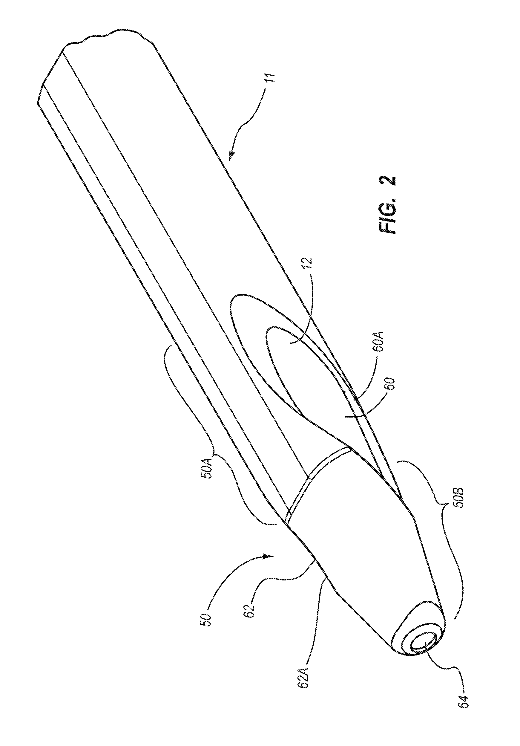
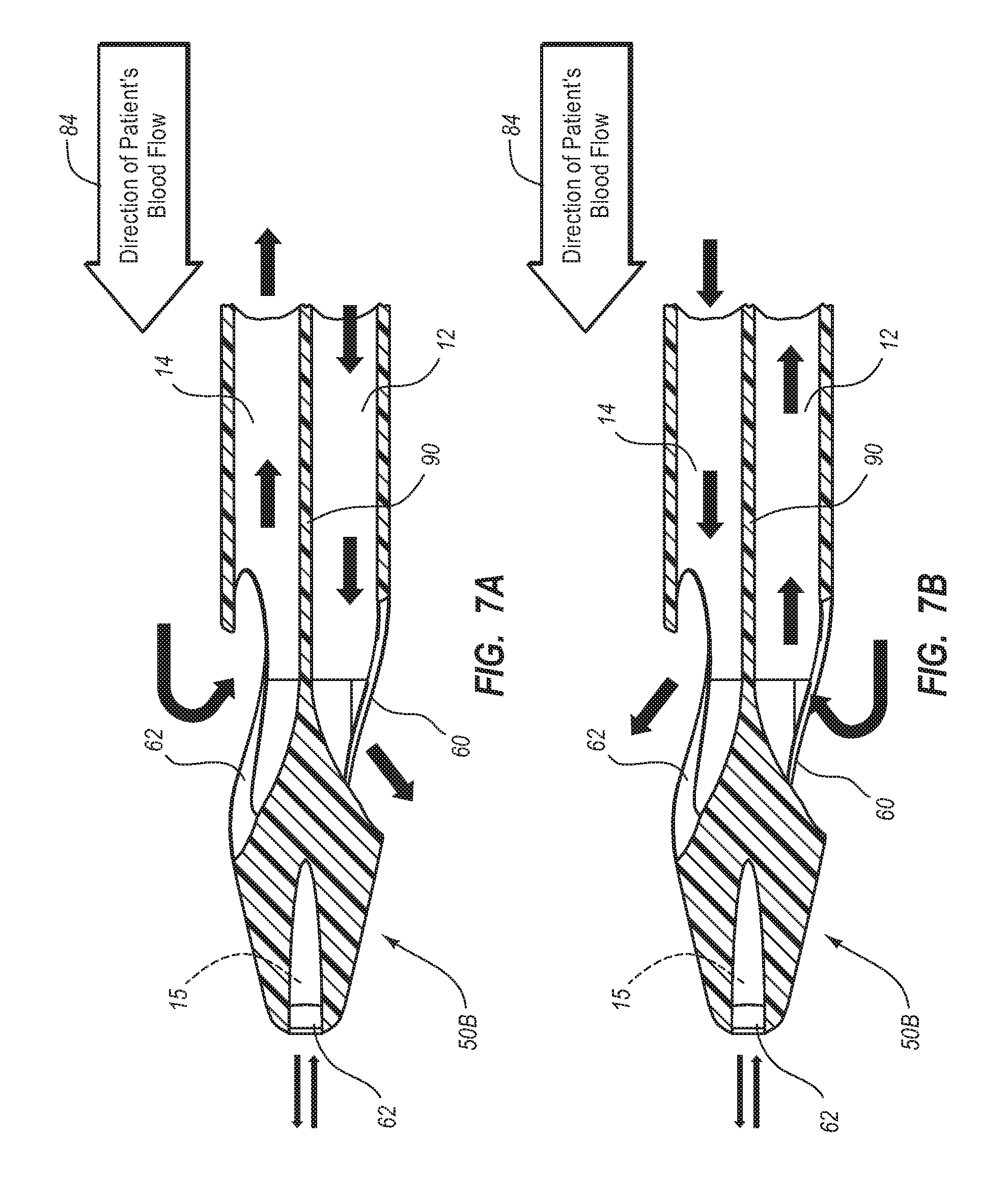
BRIEF SUMMARY
Briefly summarized, embodiments of the present invention are directed to a catheter assembly for use in accessing a vasculature or other vessel of a patient during renal replacement or other suitable therapies. In one embodiment, the catheter assembly includes a catheter body that defines at least first and second lumens. The catheter body defines a distal tip region that includes at least one venous lateral opening that is in fluid communication with the first lumen and includes a distal-facing portion, and at least one arterial lateral opening that is in fluid communication with the second lumen and includes a distal-facing portion. The at least one arterial lateral opening is opposingly positioned in a substantially un-staggered configuration with respect to the at least one venous lateral opening. A distal end opening is defined on the distal tip region and is sized to pass a fluid therethrough. In one embodiment, the distal end opening is in fluid communication with a third lumen of the catheter body that can withstand high fluid flow rates associated with power injection of contrast media, for instance.
In another embodiment, a catheter assembly including a catheter body defining a first lumen and a second lumen is disclosed. The catheter body includes a distal tip region, which in turn includes a nose portion that defines a distally converging outer surface. A venous lateral opening, in fluid communication with the first lumen, is partially defined on the distally converging outer diameter. An arterial lateral opening, in fluid communication with the second lumen, is also partially defined on the distally converging outer diameter. The venous and arterial lateral openings are symmetrically disposed in a substantially un-staggered position with respect to one another. The distal tip portion further includes a distal end opening in fluid communication with one of the venous and arterial lumens and is sized to pass a guidewire therethrough.
In yet another embodiment, the first and second lumens each generally include a reniform cross sectional shape, while the third lumen is substantially round, interposed between the first and second lumens, and is power injectable.
These and other features of the present invention will become more fully apparent from the following description and appended claims, or may be learned by the practice of the invention as set forth hereinafter.
BRIEF DESCRIPTION OF THE DRAWINGS
To further clarify the above and other advantages and features of the present invention, a more particular description of the invention will be rendered by reference to specific embodiments thereof that are illustrated in the appended drawings. It is appreciated that these drawings depict only typical embodiments of the invention and are therefore not to be considered limiting of its scope. The invention will be described and explained with additional specificity and detail through the use of the accompanying drawings in which:
FIG. 1 is a perspective view of a catheter assembly incorporating various features of an embodiment of the present invention;
FIG. 1A is a perspective view of another example of a catheter assembly configured according to one embodiment;
FIG. 2 is a perspective view of a distal tip region of the catheter assembly shown in FIG. 1, configured according to one embodiment;
FIG. 3 is a side view of the catheter distal tip region of FIG. 2;
FIG. 4 is a top view of the catheter distal tip region of FIG. 2;
FIG. 5 is an end view of the catheter distal tip region of FIG. 2;
FIG. 6 is a perspective view of the catheter distal tip region of FIG. 2, depicting various details of lateral openings defined therein;
FIG. 7A is a cross sectional view of the catheter assembly and distal tip region of FIG. 2, showing the flow of blood therethrough in a "forward" flow configuration;
FIG. 7B is a cross sectional view of the catheter assembly and distal tip region of FIG. 2, showing the flow of blood therethrough in a "reverse" flow configuration;
FIG. 8A is a cross sectional view of the catheter assembly, taken along the line 8A-8A in FIG. 4;
FIG. 8B is another cross sectional view of the catheter tip, taken along the line 8B-8B in FIG. 4;
FIG. 8C is yet another cross sectional view of the catheter tip, taken along the line 8C-8C in FIG. 4;
FIG. 8D is yet another cross sectional view of a distal tip region of the catheter assembly showing positioning of a third lumen thereof in accordance with one embodiment;
FIGS. 9A-9F depict various views of a catheter assembly including a distal tip region configured in accordance with one embodiment;
FIGS. 10A-10D are perspective, front, side, and top views, respectively, of a catheter including a distal tip region configured in accordance with one embodiment;
FIGS. 11A-11D are perspective, front, side, and top views, respectively, of a catheter including a distal tip region configured in accordance with one embodiment;
FIGS. 12A-12D are perspective, front, side, and top views, respectively, of a catheter including a distal tip region configured in accordance with one embodiment;
FIGS. 13A-13D are perspective, front, side, and top views, respectively, of a catheter including a distal tip region configured in accordance with one embodiment;
FIGS. 14A-14D are perspective, front, side, and top views, respectively, of a catheter including a distal tip region configured in accordance with one embodiment;
FIGS. 15A-15D are perspective, front, side, and top views, respectively, of a catheter including a distal tip region configured in accordance with one embodiment;
FIGS. 16A-16D are perspective, front, side, and top views, respectively, of a catheter including a distal tip region configured in accordance with one embodiment;
FIGS. 17A-17D are perspective, front, side, and top views, respectively, of a catheter including a distal tip region configured in accordance with one embodiment;
FIGS. 18A-18D are perspective, front, side, and top views, respectively, of a catheter including a distal tip region configured in accordance with one embodiment;
FIGS. 19A-19D are perspective, front, side, and top views, respectively, of a catheter including a distal tip region configured in accordance with one embodiment;
FIGS. 20A-20D are perspective, front, side, and top views, respectively, of a catheter including a distal tip region configured in accordance with one embodiment;
FIG. 21 is a perspective view of a catheter assembly according to one embodiment;
FIGS. 22A and 22B are various perspective views of a distal portion of the catheter assembly of FIG. 21;
FIGS. 23A-23C are various cross-sectional views of the distal portion of the catheter assembly of FIG. 21;
FIG. 24 is a cross-sectional view of the catheter assembly of FIG. 21;
FIG. 25 is a cross-sectional view of a catheter assembly according to one embodiment;
FIG. 26 is a cross-sectional view of a catheter assembly according to one embodiment;
FIG. 27 is a perspective view of a catheter assembly according to one embodiment; and
FIG. 28 is a cross-sectional view of the catheter assembly of FIG. 27.
DETAILED DESCRIPTION OF SELECTED EMBODIMENTS
Reference will now be made to figures wherein like structures will be provided with like reference designations. It is understood that the drawings are diagrammatic and schematic representations of example embodiments, and are not limiting of the embodiments nor are they necessarily drawn to scale.
For clarity it is to be understood that the word "proximal" refers to a direction relatively closer to a clinician using the device to be described herein, while the word "distal" refers to a direction relatively further from the clinician. For example, the end of a catheter placed within the body of a patient is considered a distal end of the catheter, while the catheter end remaining outside the body is a proximal end of the catheter. Also, the words "including," "has," and "having," as used herein, including the claims, shall have the same meaning as the word "comprising."
FIGS. 1-20D depict various features of embodiments of the present invention, which are generally directed to an acute catheter assembly for use in accessing a vasculature or other vessel of a patient during renal replacement therapies such as hemodialysis or blood purification, though the principles of the present invention may be extended to other catheters employed in other uses in addition to these. Such acute catheters are typically employed in short-term placement scenarios such as a placement of less than 30 days, though the principles to be described herein can also apply to mid-term and long term catheter placements as well.
In accordance with one example embodiment, the catheter assembly includes a distal tip region defining separate venous and arterial lateral openings, in fluid communication with corresponding venous and arterial lumens that are employed for simultaneously infusing and aspirating blood from a vein or other vessel of a patient's vasculature during hemodialysis treatments. The venous and arterial lateral openings are disposed in a substantially equivalent, non-staggered position with respect to one another so as to enable positioning thereof in a predetermined region of the vasculature. This notwithstanding, the lateral openings are configured to reduce the likelihood of recirculation by the arterial segment of treated blood just returned to the vessel by the venous segment, thus increasing catheter efficiency. Moreover, the lateral openings can be operated in a reverse flow configuration without significantly impacting catheter efficiency during hemodialysis.
Embodiments of the catheter assembly to be described herein further include a distal end opening in fluid communication with a lumen of the catheter configured to withstand relatively high pressure and flow rates typically associated with power injection. This enables aspiration or infusion of fluids to occur via this lumen independently of the venous and arterial lumens. "Power injection" is defined herein to include fluid infusion under relatively high flow rates and/or relatively high pressures. For instance, in one embodiment power injection includes fluid infusion through a catheter lumen at a flow rate of between about three and about eight milliliters per second, and/or at a pressure of between about 50 and about 250 psi.
For clarity it is to be understood that the word "proximal" refers to a direction relatively closer to a clinician using the device to be described herein, while the word "distal" refers to a direction relatively further from the clinician. For example, the end of a catheter placed within the body of a patient is considered a distal end of the catheter, while the catheter end remaining outside the body is a proximal end of the catheter. Further, the words "including," "has," and "having," as used herein, including the claims, shall have the same meaning as the word "comprising."
Reference is first made to FIG. 1, which depicts various features of a hemodialysis catheter assembly, generally designated at 10, according to one example embodiment. As shown, the catheter 10 includes an elongate catheter body 11 including a proximal end 11A and a distal end 11B. The elongate catheter body 11 defines a first lumen 12, a second lumen 14, and a third lumen 15 (FIG. 7A) that longitudinally extend from the proximal end 11A to the distal end 11B thereof. The lumens 12, 14, and 15 can have one or more cross sectional shapes along their respective lengths, including round, oval, D-cross sectional shapes, or any combination thereof. In one embodiment, the first and second lumens 12, 14 are sized so as to accommodate fluid flow rates required for hemodialysis, i.e., about 300 milliliters/min. at about 250 millimeters Hg pressure. In one embodiment, the third lumen is sized with a diameter of about 0.035 to about 0.038 inch to accommodate blood draws and fluid aspiration/infusion therethrough.
A trifurcating hub 20 is included at the catheter body proximal end 11A, providing fluid communication between the first, second, and third lumens 12, 14, 15 and arterial extension leg 16, venous extension leg 18, and power extension leg 19, respectively. The extension legs 16, 18, 19 each include a luer connector 16A, 18A, 19A, and a clamp 16B, 18B, 19B. So configured, the extension legs 16, 18 provide fluid communication with the first and second lumens 12 and 14 so as to enable the infusion or aspiration of fluids from the central venous system of a patient. As such, fluid infusion or aspiration devices, such as a hemodialysis apparatus for example, may be connected to the catheter assembly 10 via the luer connectors 16A, 18A, thus providing intravascular access to the patient. Similarly, the extension leg 19 provides fluid communication with the third lumen 15 to enable fluid infusion/aspiration from the vein when a corresponding device is connected thereto via the connector 19A. Note that the respective positions and configurations of the extension legs detailed here can change according to a particular catheter assembly design and therefore not be viewed as limiting. The catheter body 11 further includes a suture wing 21 for providing securement of the catheter body to the patient.
FIG. 2 shows the catheter assembly 10 according to another example embodiment, wherein the extension legs 16, 18 each include a pre-curved portion 16C, 18C. The pre-curved portions 16C, 18C enable the extension legs 16, 18 of the catheter assembly 10 to extend downward against the patient's body once the distal portion of the catheter assembly has been placed in the vasculature to provide patient comfort.
In greater detail, the power extension leg 19 of FIGS. 1 and 2 fluidly connects to the third lumen 15 via the trifurcating hub 20. In particular, the power extension leg 19 is configured in one embodiment to enable rapid infusion, i.e., power injection, of contrast media, useful for contrast-enhanced CT scan imaging, or other fluids into the patient vessel via the third lumen 15. Specifically, in one embodiment, the power extension leg 19 and third lumen 15 are configured to infuse fluids at a rate of between about 3 milliliters and about 8 milliliters per second and at a fluid pressure of between about 50 and 250 psi, though other flow rates and fluid pressures may also be possible. The power extension leg 19 and third lumen 15 can also be used to remove blood or other fluids alone or during simultaneous use of the first and second lumens 12 and 14, and to monitor central venous pressure with the assistance of a transducer. The power extension leg 19 and third lumen 15 are also sufficiently sized to receive a guidewire therethrough to enable insertion of the catheter assembly over the guidewire. Note that the components of the power extension leg 19 are colored purple in one embodiment to indicate power injectability. Other colors could also be used.
Both FIGS. 1 and 2 further include a distal tip region, generally designated at 50, that is configured in accordance one example embodiment of the present invention, the details of which are given below. It should be appreciated that the distal tip region to be described below can be included with hemodialysis catheters, such as those shown in FIGS. 1 and 2, or with other catheters, such as central venous catheters, for example. Indeed, the catheter assembly according to embodiments of the present invention can be adapted for use in other applications, such as chronic dialysis treatment, or where access is desired to be gained to a vessel, such as the internal jugular, subclavian, or femoral vessels, or other body lumen of a patient. Examples of such other applications include apheresis, hemoperfusion, etc.
Reference is now made to FIGS. 2-6, which show various views of a distal tip region, generally designated at 50, of the catheter assembly 10 and configured according to one example embodiment. In detail, the distal tip region 50 generally includes a terminal catheter portion 50A and a nose portion 50B disposed distally of the terminal catheter portion to define a distal end of the catheter assembly 10. The terminal catheter portion 50A, as part of the more proximal portion of the catheter body 11, is composed of suitable material(s) that exhibit qualities, such as suitable softness to allow for ease of insertion without causing vessel trauma, and biocompatibility for enabling the catheter to operate as intended. In one embodiment, the catheter body 11 is composed of material(s) including a thermoplastic polyurethane-based resin material, specifically a polyether-based, aliphatic thermoplastic polyurethane sold under the trademark TECOFLEX, namely TECOFLEX EG-60D-B20, having a Shore D hardness of approximately 60, where "B20" refers to the radiopacifier loading, i.e., barium sulfate loading at 20%. Other suitable materials can also be employed.
In contrast, the nose portion 50B includes a material relatively softer than that of the terminal catheter portion 50A so as to prevent the tip portion from damaging the vessel or other vasculature during vessel entry or transit. In one embodiment, the nose portion 50B is composed of material(s) including TECOFLEX EG-85A-B20 having a Shore A hardness of approximately 85. Notwithstanding the above description, it should be appreciated that the terminal catheter portion and the nose portion can include other materials having the desired properties as described herein and as appreciated by one skilled in the art. One non-limiting example of material that can be used for the terminal catheter portion and nose portion is silicone.
Note that in the illustrated embodiment, the nose portion 50B is joined to the terminal catheter portion 50A via a molding process during manufacture of the catheter assembly 10. In other embodiments, however, other processes for joining the nose portion to the catheter body can be employed, including for instance RF fusion (RF tipping), bonding via adhesive, integrally forming the nose portion with the catheter body, etc.
As best seen in FIGS. 3 and 4, the nose portion 50B is distally converging. In the present embodiment, the nose portion 50B is tapered so as to ease entry and passage of a distal portion of the catheter body 11 into the vasculature or other internal cavity of a patient. The nose portion 50B may be colored differently from the remainder of the catheter body 11 to indicate that the catheter assembly 10 can be employed for relatively rapid fluid aspiration and infusion via the third lumen 15 and corresponding power extension leg 19, as was described further above.
The distal tip region 50 includes various openings for enabling the infusion and aspiration of fluids while the catheter assembly 10 is placed for use within the patient vasculature. Specifically, and in accordance with one embodiment, the distal tip region includes a venous lateral opening 60, an arterial lateral opening 62, and a distal end opening 64.
In greater detail, the venous and arterial lateral openings 60 and 62 are positioned opposite one another proximate the catheter body distal end 11B and are defined in a lateral portion of an outer wall of the catheter body 11 so as to be in fluid communication with first lumen 12 and the second lumen 14, respectively, thus enabling blood or other fluids to flow via the openings to/from the lumens when the catheter assembly 10 is positioned within the patient's vasculature. The venous and arterial lateral openings 60 and 62 are defined by perimeters 60A and 62A, respectively, as best seen in FIG. 4 and described further below.
Note that each of the lateral openings 60 and 62 distally extends from the terminal catheter portion 50A into the nose portion 50B. Of course, the exact placement of the lateral openings 60 and 62 along the longitudinal length of the catheter body 11 can vary according the needs of a particular application.
FIG. 4 shows that in the present embodiment the venous and arterial lateral openings 60 and 62 are substantially un-staggered, i.e., equally placed with respect to one another along the longitudinal length of the catheter body 11 such that each is substantially disposed an equal distance from the distal catheter end 11B. Such un-staggered disposal of the lateral openings 60 and 62 enables both openings to be placed proximate a desired location within the vasculature and ensures that the recirculation rate of already treated blood through the catheter assembly 10 is held relatively constant regardless the respective directions of blood travel in/out of the lateral openings. This feature is useful should reversal of blood flow directions through the catheter be necessary. In one embodiment, the recirculation rate in either direction is less than or equal to about five percent. In another embodiment, the venous and lateral openings can be staggered.
FIGS. 2-6 further show the manner in which the venous and lateral openings 60 and 62 are defined in the distal tip region 50. The lateral openings 60 and 62 can take various shapes and configurations as will be shown further below, but in the present embodiment the lateral openings are defined by angled cross-drilled cuts through the outer wall of the catheter body 11 to establish communication with the respective first or second lumens 12, 14. In one embodiment, such cuts are referred to as "skive" cuts.
In one embodiment, a long axis of each cross-drilled cut of the lateral openings 60, 62 defines in one embodiment an angle .theta..sub.1 of about 35 degrees with a longitudinal axis of the catheter body 11, though this angle can vary in one embodiment from about greater than zero to about 90 degrees. This angular character imparts both a lateral and distal directional component to fluid flow out of either lateral opening 60, 62, as represented by the flow arrows in FIG. 4, which assists in enabling low-recirculation fluid flow out of or into either lateral opening. Each lateral opening 60 and 62 in the present embodiment is defined by identical cross cuts having the same angle .theta..sub.1 with respect to the longitudinal axis 70, though it is also possible to vary the angle generally, or to vary the angle differently for each opening.
In one embodiment, the lateral openings can be defined by a compound-angle cross cut, wherein the long axis of each lateral opening defines an angle with the catheter body longitudinal axis and with a plane dividing the first lumen and the second lumen, i.e., coplanar with the septum separating the first and second lumens proximal of the distal tip region.
An end view of the cross cut, depicted in FIG. 6, shows that the cross cut of each opening 60 and 62 in the illustrated embodiment is made so as to generally define a semicircular cavity through a peripheral portion of the distal tip region 50. This cavity is defined by a portion of a circle 72 having a radius "R," shown in FIG. 6. In the present embodiment, the cross cut that defines the lateral openings 60 or 62 is achieved via use of a cylindrical drill bit or coring tool having a radius equal to the radius R of the circle 72 and cutting through the distal tip region 50 set at the angle .theta..sub.1. For instance, in one embodiment a drill bit having a radius of 1/16 inch is used to diagonally cross cut the venous and arterial lateral openings 60 and 62 through a catheter body defining an oblong cross section, wherein the average of the major and minor diameters is approximately 0.173 inches. Note that the catheter body size in one embodiment can vary from 7-16 Fr., though other French sizes are also possible. Though shown in connection with the venous lateral opening 60, the above description applies to the arterial opening 62 as well. Note here that, though identically sized and shaped in the present embodiment, the first and second openings could have respectively differing dimensions if desired or needed for a particular application.
As a result of defining the cross cuts as just described, the venous and arterial openings 60 and 62 are defined by their respective perimeters 60A and 62A discussed above. The angle at which the cross cuts are made, together with the shape of the catheter body 11 at the point of the cuts, results in the perimeters 60A and 62A shaped as seen in the accompanying figures. As best seen in FIG. 4, each perimeter 60A and 62A defines in the present embodiment a figure-eight shape, or analemma, when viewed in a two-dimensional perspective and an elongate saddle shape when viewed in a three-dimensional perspective. Further, because a distal portion of each opening 60 and 62 is defined on a portion of the tapered nose portion 50B (best seen in FIGS. 4 and 5), each opening has a distal-facing component, best seen in FIG. 5, wherein a portion each lateral opening is distally visible.
The configuration of the venous and arterial lateral openings 60 and 62 described above provides various aspects for the catheter assembly 10. First, because of their saddle shapes, the lateral openings 60 and 62 partially extend circumferentially about the outer perimeter of the catheter body 11. This helps to prevent undesired suctioning of the distal tip region 50 to the vessel wall when one of the openings is removing blood from the vessel as the negative flow pressure of the opening is distributed about a portion of the catheter body circumference. If vessel suck-up does occur, the lateral openings 60, 62 are shaped so as to nonetheless provide acceptable fluid flow in and out of the catheter assembly 10. The relatively large size of the lateral openings 60 and 62 also assists in the prevention of occlusion or sheath formation and provides a fanned-out or wide distribution of fluid flowing out therefrom. Recirculation efficiency rates are improved as a result.
Second, the distal-facing aspect of each lateral opening 60 and 62 assists in imparting a distal direction to fluids being ejected therefrom. This enables the ejected fluid to distally flow away from one respective lateral opening and distal-to proximal flow into the other lateral opening even when the catheter body 11 is positioned against a vessel wall. In addition, the lateral openings 60, 62 are symmetrically opposed, in direction from one another, i.e., a 180-degree separation as best shown in FIG. 4, so as to ensure fluid entry and exit from the lateral openings occurs on opposite sides of catheter assembly 10, further reducing recirculation. Furthermore, this symmetric positioning produces a "criss-cross" relationship between the lateral openings 60 and 62, as best seen in FIG. 3, which assists in reducing recirculation. Moreover, similar fluid flow characteristics are realized even when fluid flow through the catheter assembly 10 is reversed, as discussed further below. In addition, the lateral opening configuration described herein minimizes radical redirection of the fluid upon exiting the catheter body 11 via either of the lateral openings 60 or 62, which in turn prevents fluid turbulence and possible clotting or hemolysis.
As shown in FIGS. 2-6, the distal end opening 64 is distally located at the distal end of the distal tip region nose portion 50 and is in fluid communication with the third lumen 15 so as to enable high flow rate infusion, i.e., power injection of contrast media or other fluids such as TPN nutritional fluid and medications into the vessel, as well as the removal of blood from the vessel during catheter use. In the case of infusion of contrast media or medications into the vessel, placement of the distal end opening 64 distally of the first and second openings 60 and 62 advantageously results in minimization of contrast media/medication intake into either of the first or second openings if the infusion takes place simultaneously with fluid passage through the venous and arterial openings 60 and 62, such as during hemodialysis or other treatments.
Note that, in one embodiment a guidewire can be inserted through the distal end opening 64, the third lumen 15, and the power extension leg 19 during initial or exchange catheter placement in the patient vasculature. Also note that the relatively proximate placement of the three openings 60, 62, and 64 in the distal portion of the catheter body 11 enables each opening to be placed near desired location within the vasculature, such as the superior vena cava ("SVC").
Reference is now made to FIGS. 7A and 7B in describing flow characteristics with respect to the configuration of the distal tip region 50 of the catheter assembly 10 according to the present embodiment. FIGS. 7A and 7B show the distal tip region 50 after the catheter assembly 10 has properly positioned within a vessel of a patient. Arrow 84 shows the direction of blood flow past the distal tip region 50 within the patient's vessel.
In greater detail, FIG. 7A shows fluid flow through the distal tip region 50 in a "forward" direction, wherein blood is aspirated by the second lumen 14, or "uptake" lumen, for removal from the body and treatment by a hemodialysis apparatus or for some other suitable purpose. Aspirated blood enters the second lumen 14 via the arterial lateral opening 62 of the distal tip region 50. Similarly, blood is infused, or returned, to the vessel by the first lumen 12, or "return" lumen, after treatment by a hemodialysis apparatus or some other suitable purpose. Infused blood exits the first lumen 12 from the venous lateral opening 60. Note that the lateral orientation of the venous and arterial lateral openings 60, 62 provides for low recirculation of already-treated blood within the vessel, recirculation being defined as already-treated blood that is returned to the bloodstream via the venous lumen being immediately aspirated by the arterial lumen to be re-treated. Such recirculation is undesirable as it results in lower treatment efficiency, resulting in longer treatment time.
During hemodialysis procedures, it is sometimes necessary to reverse the blood flow through the catheter assembly 10. FIG. 7B shows fluid flow through the distal tip region 50 during such a "reverse" flow situation. In contrast to the forward flow conditions of FIG. 7A, the second lumen 14 in FIG. 7B is employed to infuse blood into the vessel while the first lumen 12 aspirates blood from the vessel. In this configuration, the infused blood enters the vessel via the arterial lateral opening 62, while the aspirated blood is removed via the venous lateral opening 60. Again, the lateral orientation of the venous and arterial lateral openings 60, 62 provides for low recirculation of already-treated blood within the vessel. Thus, it is seen that low recirculation results regardless of the direction in which the catheter is operating.
FIGS. 7A and 7B further show that fluid can be aspirated or infused via the distal end opening 64 in fluid communication with the third lumen 15 before, after, or during infusion/aspiration by the venous and arterial lateral openings 60, 62. As mentioned, the third lumen 15 and distal end opening 64 are configured so as to withstand relatively high pressurized fluid flow infusion into the vessel. It is appreciated that in other embodiments, more than one of the catheter lumens can be configured for high pressurized fluid flow infusion, if desired.
It should be appreciated that the labels "venous" and "arterial" as used above in describing the various components of the present catheter assembly are employed for sake of convenience in describing aspects of present embodiments. Indeed and as just described, though the arterial lateral opening is normally employed in hemodialysis procedures for aspirating blood from the blood vessel in which the catheter is disposed and the venous lateral opening for returning already treated blood to the vessel, this can be reversed such that blood is returned via the arterial lateral opening and aspirated by the venous lateral opening. As such, embodiments of the present invention should not be considered limited by the use of this and other descriptive terminology herein.
Reference is now made to FIGS. 8A-8C, which depict various details regarding the catheter body 11. In detail, FIG. 8A shows a cross sectional view of the catheter body 11 at a point proximal to the distal tip region 50, showing the first lumen 12, the second lumen 14, and the third lumen 15. The three lumens 12, 14, 15 are defined along the longitudinal length of the catheter body 11 and bounded by an outer perimeter or wall 86. The outer wall 86 of the catheter body 11 in the present embodiment defines an oblong shape and includes a transverse axis 88 that intersects the first and second lumens 12, 14 and spans the width of the catheter body. Placement of the first and second lumens 12, 14 adjacent one another, with the third lumen 15 positioned therebelow, provides a robust lumen configuration that resists inadvertent closure of lumens via kinking of the catheter body 11. In addition, the oblong cross sectional configuration of the catheter body 11 enables circular cross sectional shapes to be employed for the lumens 12, 14, and 15, which are relatively more efficient than "D"-shaped or other shaped lumens in terms of fluid flow.
As seen in FIG. 8B and as previously described, the venous lateral opening 60 is defined so that it intercepts the first lumen 12, while the arterial lateral opening is defined so that it intercepts the second lumen 14. As such, the first lumen 12 establishes fluid communication between the venous extension leg 18 and the venous lateral opening 60, while the second lumen 14 establishes fluid communication between the arterial extension leg 16 and the arterial lateral opening 62. In one embodiment, the angled cross cuts that define the venous and arterial openings 60 and 62 are made tangentially with respect to a septum 90 separating the first and second lumens 12, 14 such that the septum wall remains intact as a barrier between the two lumens.
FIGS. 8A-8C successively depict the manner in which the third lumen is raised from a bottom-central location along the length of the catheter body 11 to a central position upon its exit at the distal end opening 64, as shown in FIG. 5. Of course, other lumen position configurations are also possible.
It is appreciated that various modifications may be made to the catheter assembly configurations described above. It is noted that for purposes of clarity, only selected differences between the foregoing and following embodiments are described. For instance, FIGS. 9A-9F depict a distal tip region 150 including a terminal catheter portion 150A integrally formed with the catheter body 11 and a nose portion 150B including a relatively low hardness, e.g., soft, material and joined to the terminal catheter portion 150A in a manner similar to that already described above in connection with FIGS. 2-6.
The distal tip region 150 defines a venous lateral opening 160 in fluid communication with the first lumen 12 and an arterial lateral opening 162 in fluid communication with the second lumen 14. A distal end opening 164 is also defined at a distal end of the nose portion 150B. The catheter assembly as configured in FIGS. 9A-9F is a dual lumen device in that it includes only two lumens 12 and 14 (FIG. 9E). As best seen in FIG. 9F, therefore, the distal end opening 164 does not communicate with a third lumen, but rather with a guidewire channel 164A defined by the nose portion 150B, which in turn communicates with the first lumen 12. In this way, a guidewire pathway is established through the catheter body 11 and distal tip region 150 to enable the catheter assembly to be inserted over a guidewire during initial placement and catheter exchange procedures.
FIG. 9E depicts a cross sectional view of the catheter body proximal of the distal tip region 150. As shown, top and bottom portions of an outer wall 186 of the catheter body 11 include thickened regions 186A, which provide added kink resistance to the catheter body.
By virtue of its communication with the first lumen 12, the guidewire channel 164A provides an added fluid outlet/inlet for the first lumen via the distal end opening 164, thus providing an additional fluid pathway that further reduces recirculation during operation of the catheter. This fluid communication also maintains the guidewire channel 164A patent via the flow of blood therethrough so as to prevent occlusion thereof. Further note that, though it is centrally located at the distal end of the nose portion 150B, the venous lateral opening 164 can be positioned such that it and the corresponding guidewire channel 164A are in longitudinal linear alignment with the first lumen 12. Further, the venous lateral opening and the corresponding guidewire channel can be configured as to be in communication with the second lumen or both the first and second lumens, if desired.
FIGS. 10A-10D and 11A-11D are further examples of a dual lumen catheter assembly configuration, in accordance with example embodiments thereof. The distal tip regions 250/350 each include a terminal catheter portion 250A/350A and a nose portion 250B/350B at which are defined a venous lateral opening 260/360, an arterial lateral opening 262/362, and a distal end opening 264/364. A guidewire channel 264A/364A is defined between the distal end opening 264/364 to the first lumen 12 so as to be in communication therewith. As can be seen in comparison, the lateral openings 260, 262 of FIGS. 10A-10D are differently shaped from corresponding lateral openings 360, 362 of FIGS. 11A-11D. Further, the nose portion 250B (FIG. 10A) is distally converging in a tapered configuration, whereas the nose portion 350B (FIG. 11A) distally converges in a rounded configuration to define a bullet-shape. Note also that the venous and arterial lateral openings of the dual lumen embodiments describe herein include distal-facing portions, as best seen in FIGS. 10B and 11B, offering characteristics similar to those outlined above in connection with the discussion relating to FIGS. 2-6.
FIGS. 12A-20D depict possible configurations of a catheter assembly distal tip region including three lumens, according to additional example embodiments. As they share aspects with the embodiment described above in connection with FIGS. 2-7B, only selected aspects of the embodiments to follow will be discussed below.
FIGS. 12A-12D depicts a catheter assembly distal tip region 450, including a terminal catheter portion 450A and a nose portion 450B. The distal tip region 450 further includes a venous lateral opening 460 in fluid communication with the first lumen 12 and an arterial lateral opening 462 in fluid communication with the second lumen 14. A distal end opening 464 is also defined at a distal end of the nose portion 450B. In the present embodiment, the lateral openings 460 and 462 each define a trapezoidal perimeter when viewed from the perspective of FIG. 12D, and are symmetrically opposed from one another.
FIGS. 13A-13D depicts a catheter assembly distal tip region 550, including a terminal catheter portion 550A and a nose portion 550B. The distal tip region 550 further includes a venous lateral opening 560 in fluid communication with the first lumen 12 and an arterial lateral opening 562 in fluid communication with the second lumen 14. A distal end opening 564 is also defined at a distal end of the nose portion 550B. In the present embodiment, the lateral openings 460 and 462 each define a stepped perimeter when viewed from the perspective of FIG. 13D, and are symmetrically opposed from one another.
FIGS. 14A-14D depict a catheter assembly distal tip region 650, including a terminal catheter portion 650A and a nose portion 650B. The distal tip region 650 further includes a venous lateral opening 660 in fluid communication with the first lumen 12 and an arterial lateral opening 662 in fluid communication with the second lumen 14. A distal end opening 664 is also defined at a distal end of the nose portion 650B and is axially offset from a central axis of the catheter body 11. In the present embodiment, the lateral openings 660 and 662 each define an oval perimeter when viewed from the perspective of FIG. 12C, and are symmetrically opposed from one another, as best seen in FIG. 14D.
FIGS. 15A-15D depict a catheter assembly distal tip region 750, including a terminal catheter portion 750A and a nose portion 750B. The distal tip region 750 further includes a venous lateral opening 760 in fluid communication with the first lumen 12 and an arterial lateral opening 762 in fluid communication with the second lumen 14. A distal end opening 764 is also defined at a distal end of the nose portion 750B and is axially offset from a central axis of the catheter body 11. In the present embodiment, the lateral openings 760 and 762 each define an oval perimeter when viewed from the perspective of FIG. 15C, and are symmetrically opposed from one another, as best seen in FIG. 15D.
FIGS. 16A-16D depict a catheter assembly distal tip region 850, including a venous lateral opening 860 in fluid communication with the first lumen 12 and an arterial lateral opening 862 in fluid communication with the second lumen 14. A distal end opening 864 is also defined at a distal end of the distal tip region 850 and is axially offset from a central axis of the catheter body 11. In the present embodiment, the lateral openings 860 and 862 are separated by a septum 890, and each defines a partial oval perimeter when viewed from the perspective of FIG. 16C, and are symmetrically opposed from one another, as best seen in FIG. 16D.
FIGS. 17A-17D depict a catheter assembly distal tip region 950, including a venous lateral opening 960 in fluid communication with the first lumen 12 and an arterial lateral opening 962 in fluid communication with the second lumen 14. A distal end opening 964 is also defined at a distal end of the distal tip region 850 and is axially offset from a central axis of the catheter body 11. In the present embodiment, the lateral openings 960 and 962 are separated by a septum 990, and each defines an acute angle-shaped perimeter together with a portion of an outer catheter body wall 986 when viewed from the perspective of FIG. 16C. As before, the lateral openings 960, 962 are symmetrically opposed from one another, as best seen in FIG. 17D.
FIGS. 18A-18D depict a catheter assembly distal tip region 1050, including a terminal catheter portion 1050A and a nose portion 1050B. The distal tip region 1050 further includes a venous lateral opening 1060 in fluid communication with the first lumen 12 and an arterial lateral opening 1062 in fluid communication with the second lumen 14. A distal end opening 1064 is also defined at a distal end of the distal tip region nose portion 1050B and is centrally disposed with respect to a central axis of the catheter body 11. In the present embodiment, the lateral openings 1060 and 1062 are separated by a septum 1090, and each defines a partial oval perimeter when viewed from the perspective of FIG. 18C. As before, the lateral openings 1060, 1062 are symmetrically opposed from one another, as best seen in FIG. 18D.
FIGS. 19A-19D depicts a catheter assembly distal tip region 1150, including a nose portion 1150B. The distal tip region 1150 further includes a venous lateral opening 1160 in fluid communication with the first lumen 12 and an arterial lateral opening 1162 in fluid communication with the second lumen 14. A distal end opening 1164 is also defined at a distal end of the distal tip region 1150 and is axially offset from a central axis of the catheter body 11. In the present embodiment, the lateral openings 1160 and 1162 each define a triangular perimeter when viewed from the perspective of FIG. 19D, and are symmetrically opposed from one another as best seen in FIG. 19D.
FIGS. 20A-20D depict a catheter assembly distal tip region 1250, including a terminal catheter portion 1250A and a nose portion 1250B. The distal tip region 1250 further includes a venous lateral opening 1260 in fluid communication with the first lumen 12 and an arterial lateral opening 1262 in fluid communication with the second lumen 14. A distal opening 1264 is also defined on the nose portion 1250B and is axially offset from a central axis of the catheter body 11. In the present embodiment, the lateral openings 1260 and 1262 are separated by a septum 1290, and each defines a frustoconical perimeter when viewed from the perspective of FIG. 20C. As before, the lateral openings 1260, 1262 are symmetrically opposed from one another, as best seen in FIG. 20D. In addition to the lateral openings 1260, 1262, the terminal catheter portion 1250A further includes a plurality of venous openings 1260A and a plurality of arterial openings 1262A. The openings 1260A, 1262A are relatively smaller than the lateral openings 1260, 1262, and are distributed about the perimeter of the catheter body so as to further reduce the possibility of vessel wall suck-up.
FIGS. 21-24 depict various details of a catheter assembly 1310 according to one embodiment. Note that the embodiments described below include various similarities to the embodiments described above; as such, only selected aspects will be discussed below.
As shown, the catheter assembly 1310 includes an elongate catheter tube, or catheter body 1311, which defines a plurality of lumens extending from a proximal end 1311A to a distal end 1311B. The proximal end 1311A of the catheter body 1311 is operably attached to a bifurcation 1320, which in turn is operably attached to extension legs, namely an arterial extension leg 1316, a venous extension leg 1318, and a power extension leg 1319 suitable for power injection of a fluid therethrough. The number of catheter body lumens, extension legs, and their respective configurations can vary from what is shown and described herein. For instance, though shown in FIG. 21 as straight, the arterial and venous extension legs 1316, 1318 can each be curved in a U-shaped configuration, in one embodiment. These and other modifications are contemplated. Note also that "bifurcation" is understood to include a hub that provide two or more fluid pathways.
With continuing reference to FIG. 21, reference is made to FIGS. 22A and 22B, which depict distal portions of the catheter assembly 1310 and its elongate catheter body tube 1311, according to the present embodiment. As shown, the distal portion of the catheter body 1311 includes features similar to those shown in FIGS. 1-5 (discussed further above), including a tapered distal tip region 1350, in contrast to the cylindrically flattened oval-shaped outer surface of the more proximal portion of the catheter body, a venous lateral opening 1360, and an arterial lateral opening 1362. The arterial and venous and arterial lateral openings 1360 and 1362 are in fluid communication with respective arterial and venous lumens, which are referenced below and defined by the catheter body 1311. Each of the venous and arterial lateral openings 1360 and 1362 is defined by an angled skive cut so as to impart an angular direction component, with respect to the longitudinal axis of the catheter tube 1311, to fluid entering (via the arterial distal opening) or exiting (via the venous distal opening) the catheter tube, as before.
A third lumen distal end opening 1364 is included at the distal end of the distal tip region 1350 and is in fluid communication with a third lumen defined by the catheter body 1311, as discussed below. In addition, side holes 1342 are included in the catheter body 1311 proximal to the distal tip region 1350, which are in fluid communication with one of the arterial and venous lumens. Such side holes provide an alternate fluid path in addition to the venous and arterial lateral openings 1360, 1362. Note that the particular configuration of the various lateral and side hole openings can vary from what is shown and described herein.
FIGS. 23A-23C depict the lumen configuration of the catheter body 1311 according to the present embodiment. As shown, an outer perimeter, or outer wall 1386 having a substantially flattened oval cross-sectional configuration defines the external portion of the catheter 1311. Indeed, the outer wall 1386 bounds a first, arterial lumen 1312, a second, venous lumen 1314, and a third lumen 1315, as mentioned above. A septum 1390 cooperates with the outer wall 1386 to define the particular shape configurations of the three lumens 1312, 1314, and 1315, which each substantially extend the longitudinal length of the catheter body 1311. FIG. 23B shows the manner in which the arterial lumen 1312 and venous lumen 1314 communicate with the arterial lateral opening 1362 and the venous lateral opening 1360, while FIG. 23C shows the manner in which the third lumen 1315 extends distally toward the distal end opening 1364 on the distal tip region 1350.
FIG. 24 depicts further details regarding the cross-sectional lumen configuration of the catheter body 1311, according to the present embodiment. As shown, the flattened oval outer wall 1386 and the septum 1390 of the catheter body 1311 define the arterial lumen 1312, the venous lumen 1314, and the third lumen 1315, as mentioned above. FIG. 24 shows that the third lumen 1315 has a cross-sectional shape that is substantially round and is configured in one embodiment to withstand fluid pressures typically associated with power injection, e.g., about 300 psi in one example.
The cross-sectional configurations of the arterial and venous lumens 1312, 1314 are mirror projections of each other as taken across the center line ("CL") indicated at 1389 in FIG. 24. In particular, both the arterial and venous lumens 1312, 1314 cross-sectionally define a deformed kidney bean-shaped cross-sectional lumen profile, also referred to herein as a modified reniform shape. In greater detail, each of the arterial and venous lumens 1312, 1314 cross-sectionally defines a concavely-shaped portion, or concavity 1394, which contributes to the reniform lumen shape. The concavity 1394 for each lumen 1312, 1314 is disposed above a transverse axis 1388 of the catheter body 1311 as shown in and from the perspective of FIG. 24. Disposal of the concavity 1394 of each lumen 1312, 1314 above the transverse axis 1388, as opposed to the concavity being centered on the transverse axis results in a modified reniform configuration, though it is appreciated that the size and location of the concavity can vary from what is shown and described herein. Indeed, in one embodiment the concavity can be positioned so as to define a general reniform (un-deformed kidney bean) shape.
Each lumen 1312, 1314 further includes an arcuate portion, or major arc 1398, opposite the respective concavity 1394 that defines an outer portion of each lumen adjacent the outer wall 1386. The major arc 1398 of each lumen 1312, 1314 is bounded on either end by a top corner 1396A and a bottom corner 1396B. This configuration interposes the top corner 1396A between the major arc 1398 and the concavity 1394. The top and bottom corners 1396A and 1396B are substantially rounded to ensure a laminar flow of fluids through the arterial and venous lumens 1312, 1314, thus desirably preventing areas of fluid flow stagnation.
As shown in FIG. 24, the septum 1390 is included to separate the arterial lumen, 1312, the venous lumen 1314, and the third lumen 1315. Centered on the center line 1389, the septum 1390 includes a unified portion 1390A that generally extends downward from the transverse axis 1388 (from the perspective shown in FIG. 24) and a bifurcated portion 1390B that generally extends upward from the transverse axis. Particularly, the septum 1390 helps define the aformentioned shapes of the lumens. For example, the unified portion 1390A of the septum 1390 generally defines an hourglass-like cross-sectional shape to help define the rounded bottom corners 1396B and the inner portions of both the arterial lumen 1312 and venous lumen 1314, while the bifurcated portion 1390B of the septum cooperates with the outer wall 1386 to define the cross-sectional shape of the third lumen 1315 and the concavities 1394 of the arterial and venous lumens. Note also that the general hourglass configuration of the septum 1390 adds structural strength to the septum.
The cross-sectional configuration shown in FIG. 24 in the present embodiment extends from the proximal end 1311A of the catheter body 1311 distally to the arterial and venous lateral openings 1362, 1360, though this can be modified in other embodiments. It is noted that the various cross-sectional features of the catheter body 1311 described immediately above can vary in size, shape, and position from what is shown and described herein.
According to one embodiment, the various features described above include the following cross-sectional dimensions: the perimeter of the outer wall 1386 includes a width of about 0.195 inch and a height of about 0.128 inch; the diameter of the third lumen is about 0.040 inch; the thickness of the unified portion 1390A of the septum 1390 is about 0.015 inch; the thickness of each branch of the bifurcated portion 1390B of the septum 1390 at the midpoint of the respective concavity 1394 is about 0.010 inch; the distance between the outer surface of the outer wall and the nearest point of the third lumen is about 0.010 inch; the thickness of the outer wall at about the midpoint of the major arc 1398 is about 0.015 inch; the radius of each concavity of the identical arterial and venous lumens 1312, 1314 as measured from a center point of the third lumen is about 0.030 inch; the radius of each top corner 1396A is about 0.012 inch; the radius of each bottom corner 1396B is about 0.020 inch; the radius of each major arc is about 0.052 inch; the radius at the end of the concavity opposite the top corner (at about the transverse axis 1388) is about 0.030 inch; and the distance between the outer surface of the outer wall and the nearest point of arterial or venous lumen proximate the bottom corner thereof is about 0.010 inch. Note that the lumen configuration of the present embodiment enables fluid flow therethrough equal to a known 13 French-sized catheter while occupying the size of only a 12 French catheter. Of course, the size of the catheter body and its respective lumens can be scaled as needed/desired.
The catheter body 1311 in one embodiment includes a suitable thermoplastic such as polyurethane, for instance. In some embodiments, polyurethane thermoplastics sold under the marks TECOFLEX.RTM., CARBOTHANE.RTM., CHRONOFLEX.RTM., and QUADRIFLEX.RTM. can be used to form the catheter tube. Note that other suitable, biocompatible materials can also be used. In one embodiment, the catheter tube 12 includes a polyurethane with a 60 D Shore hardness, which assists in preventing kinking, enabling power injection therethrough, and improving insertability into the body of a patient in an acute dialysis scenario, for instance. In other non-limiting embodiments, the hardness of the catheter tube can vary from about 55D to about 65D. Desired characteristics for the material from which the catheter body is formed in one embodiment include thermosensitivity such that the material softens after insertion into the patient body, and suitable polymer strength to withstand power injection pressures to which the catheter assembly may be subjected.
In one embodiment, the atraumatic tip of the distal tip region 1350 includes a polyurethane with an 85A Shore hardness. In one non-limiting example, the atraumatic tip can range from 85A to 75A Shore hardness. In one embodiment, the material of the catheter body 1311 and atraumatic tip can include a radiopaque material, such as barium or tungsten, to enable visibility of the catheter assembly under x-ray imaging.
FIG. 25 depicts the catheter body 1311 according to another embodiment, wherein the arterial and venous lumens 1312, 1314 include a differing cross-sectional configuration from that shown in FIG. 24. As shown, the substantially identical arterial and venous lumens 1312, 1314 each cross-sectionally define the major arc 1398 and opposite thereto a flattened side 1402, defined by the septum 1390.
FIG. 26 depicts the catheter body 1311 according to another embodiment, wherein the arterial and venous lumens 1312, 1314 include a differing cross-sectional configuration from that shown in FIG. 24. As shown, a fourth lumen 1410, substantially round in cross-sectional shape, is included. Further, the substantially identical arterial and venous lumens 1312, 1314 each cross-sectionally define the major arc 1398 and opposite thereto a convex portion 1414, defined by the septum 1390. In particular, the septum 1390 includes a centrally disposed unified portion 1390A and a first and second bifurcated portion 1390B, 1390C that are disposed on either side of the unified portion and largely define the third lumen 1315 and fourth lumen 1410.
FIGS. 27 and 28 depict various details of a catheter assembly 1510 according to one embodiment. Note that the embodiments described below include various similarities to the embodiments described above; as such, only selected aspects will be discussed below.
As shown, the catheter assembly 1510 includes an elongate catheter tube, or catheter body 1511, which defines a plurality of lumens extending from a proximal end to a distal end thereof. The proximal end of the catheter body 1511 is operably attached to a bifurcation 1520, which in turn is operably attached to extension legs, namely an arterial extension leg 1516 and a venous extension leg 1518. The number of catheter body lumens, extension legs, and their respective configurations can vary from what is shown and described herein. For instance, though shown in FIG. 27 as straight, the arterial and venous extension legs 1316, 1318 can each be curved in a U-shaped configuration, in one embodiment. These and other modifications are contemplated.
The distal portion of the catheter body 1511 includes features similar to those shown in FIGS. 1-5 (discussed further above), including a tapered distal tip region in contrast to the cylindrically flattened oval-shaped outer surface of the more proximal portion of the catheter body, a venous lateral opening 1560, and an arterial lateral opening 1562. The venous and arterial lateral openings 1560 and 1562 are in fluid communication with respective venous and arterial lumens, which are referenced below and defined by the catheter body 1511. Each of the venous and arterial lateral openings 1560 and 1562 is defined by an angled skive cut so as to impart an angular direction component, with respect to the longitudinal axis of the catheter tube 1511, to fluid entering (via the arterial distal opening) or exiting (via the venous distal opening) the catheter tube, as before.
A distal end opening 1564 is included at the distal end of the distal tip region and is in fluid communication with the venous lumen, described below, though the distal end opening could be in communication with the arterial lumen in another embodiment. In addition, side holes 1542 are included in the catheter body 1511 proximal to the distal tip region, which are in fluid communication with one of the arterial and venous lumens. Such side holes provide an alternate fluid path in addition to the venous and arterial lateral openings 1560, 1562. Note that the particular configuration of the various lateral and side hole openings can vary from what is shown and described herein.
FIG. 28 depicts further details regarding the cross-sectional lumen configuration of the catheter body 1511, according to the present embodiment. As shown, an outer perimeter, or outer wall 1586 having a substantially flattened oval cross-sectional configuration defines the external portion of the catheter 1511. Indeed, the outer wall 1586 bounds a first, arterial lumen 1512 and a second, venous lumen 1514, as mentioned above. A septum 1590 cooperates with the outer wall 1586 to define the particular shape configurations of the two lumens 1512 and 1514, which each substantially extend the longitudinal length of the catheter body 1511. As discussed, the arterial lumen 1512 and the venous lumen 1514 communicate with the arterial lateral opening 1562 and the venous lateral opening 1560, respectively.
FIG. 28 depicts further details regarding the cross-sectional lumen configuration of the catheter body 1511, according to the present embodiment. As shown, the flattened oval outer wall 1586 and the hourglass-shaped septum 1590 of the catheter body 1511 define the arterial lumen 1512 and the venous lumen 1514, as mentioned above. The cross-sectional configurations of the arterial and venous lumens 1512, 1514 are mirror projections of each other as taken across the center line ("CL") indicated at 1389 in FIG. 28. In particular, both the arterial and venous lumens 1512, 1514 cross-sectionally define a modified ellipse cross-sectional lumen profile. In greater detail, each of the arterial and venous lumens 1512, 1514 cross-sectionally defines a first, minor arc 1594 adjacent and defined by the hourglass-shaped septum 1590, bounded by two corners: a top corner 1596A and a bottom corner 1596B. A second, major arc 1598 extends from each of the corners 1596A, 1596B on a side opposite the septum 1590 and adjacent the outer wall 1586 to define the rest of each lumen 1512, 1514. This configuration interposes both the top corner 1596A and the bottom corner 1596B between the major arc 1598 and the minor arc 1594. The top and bottom corners 1596A and 1596B are substantially rounded to ensure a laminar flow of fluids through the arterial and venous lumens 1512, 1514, thus desirably preventing areas of fluid flow stagnation.
As shown in FIG. 28, the septum 1590 separates the arterial lumen 1512 and the venous lumen 1514. Centered on the center line 1389, the septum 1590 defines an hourgalss cross-sectional shape equally distributed about the transverse axis 1388 and helps define the aformentioned shapes of the lumens. Note that the general hourglass configuration of the septum 1590 adds structural strength to the septum.
The cross-sectional configuration shown in FIG. 28 in the present embodiment extends from the proximal end of the catheter body 1511 distally to the arterial and venous lateral openings 1562, 1560, though this can be modified in other embodiments. It is noted that the various cross-sectional features of the catheter body 1511 described immediately above can vary in size, shape, and position from what is shown and described herein.
According to one embodiment, the various features described above include the following cross-sectional dimensions: the perimeter of the outer wall 1386 includes a width of about 0.173 inch and a height of about 0.115 inch; the thickness of the septum 1390 at the transverse axis 1388 is about 0.015 inch; the thickness of outer wall along the major arc 1598 is about 0.010 inch; the radius of the minor arc 1594 is about 0.100 inch; the radius of the major arc 1598 is about 0.050 inch; the width of each lumen 1512, 1514 at the transverse axis 1388 is about 0.072 inch; and the radius of each corner 1596A, 1596B is about 0.016 inch. Note that the above dimensions pertain to a catheter assembly 1510 having an 11 French size; of course, the size of the catheter body and its respective lumens can be scaled as needed/desired. The catheter body 1511 and its atraumatic tip can include suitable materials as have been described further above.
Embodiments of the present invention may be embodied in other specific forms without departing from its spirit or essential characteristics. The described embodiments are to be considered in all respects only as illustrative, not restrictive. The scope of the embodiments of the present invention is, therefore, indicated by the appended claims rather than by the foregoing description. All changes that come within the meaning and range of equivalency of the claims are to be embraced within their scope.
* * * * *
References
D00000
D00001
D00002
D00003
D00004
D00005
D00006
D00007
D00008
D00009
D00010
D00011
D00012

D00013

D00014
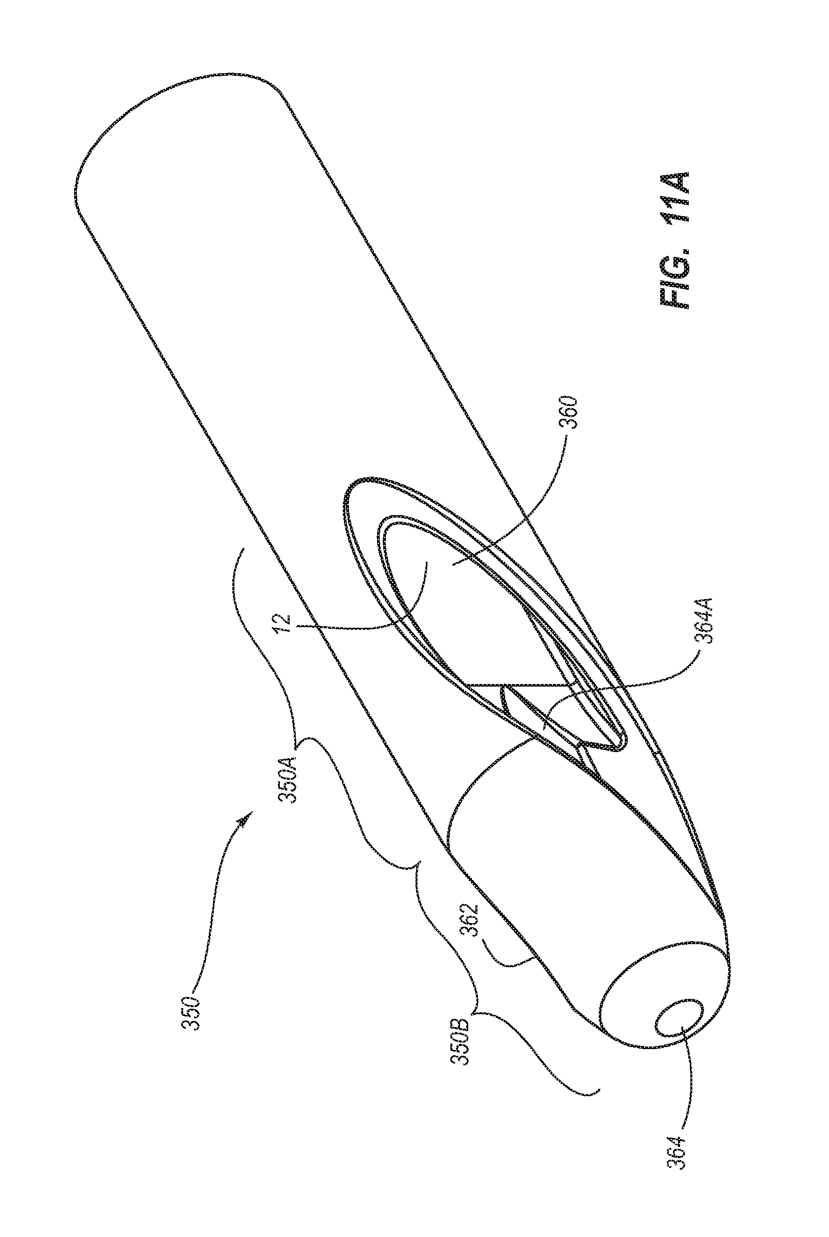
D00015
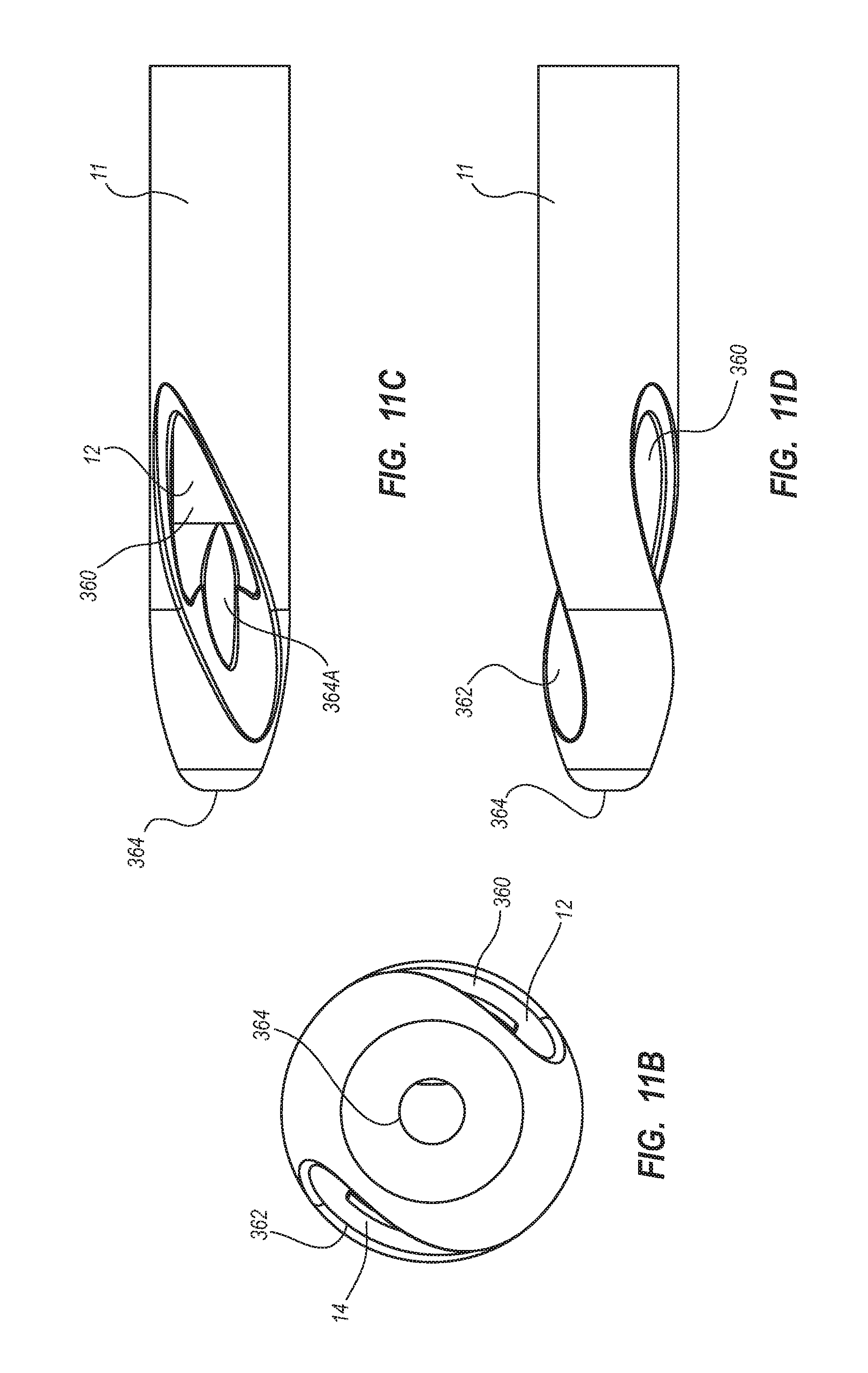
D00016
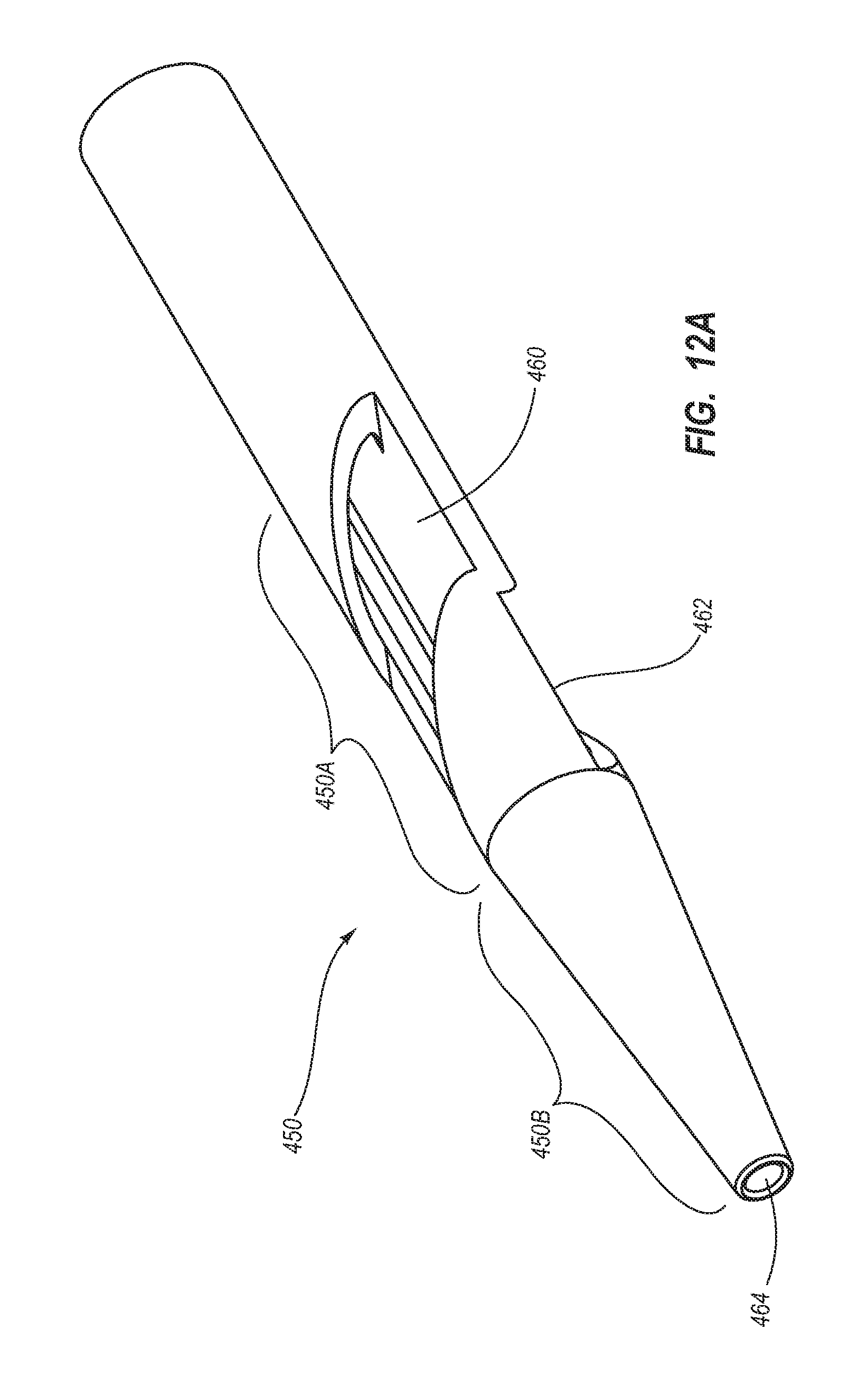
D00017

D00018
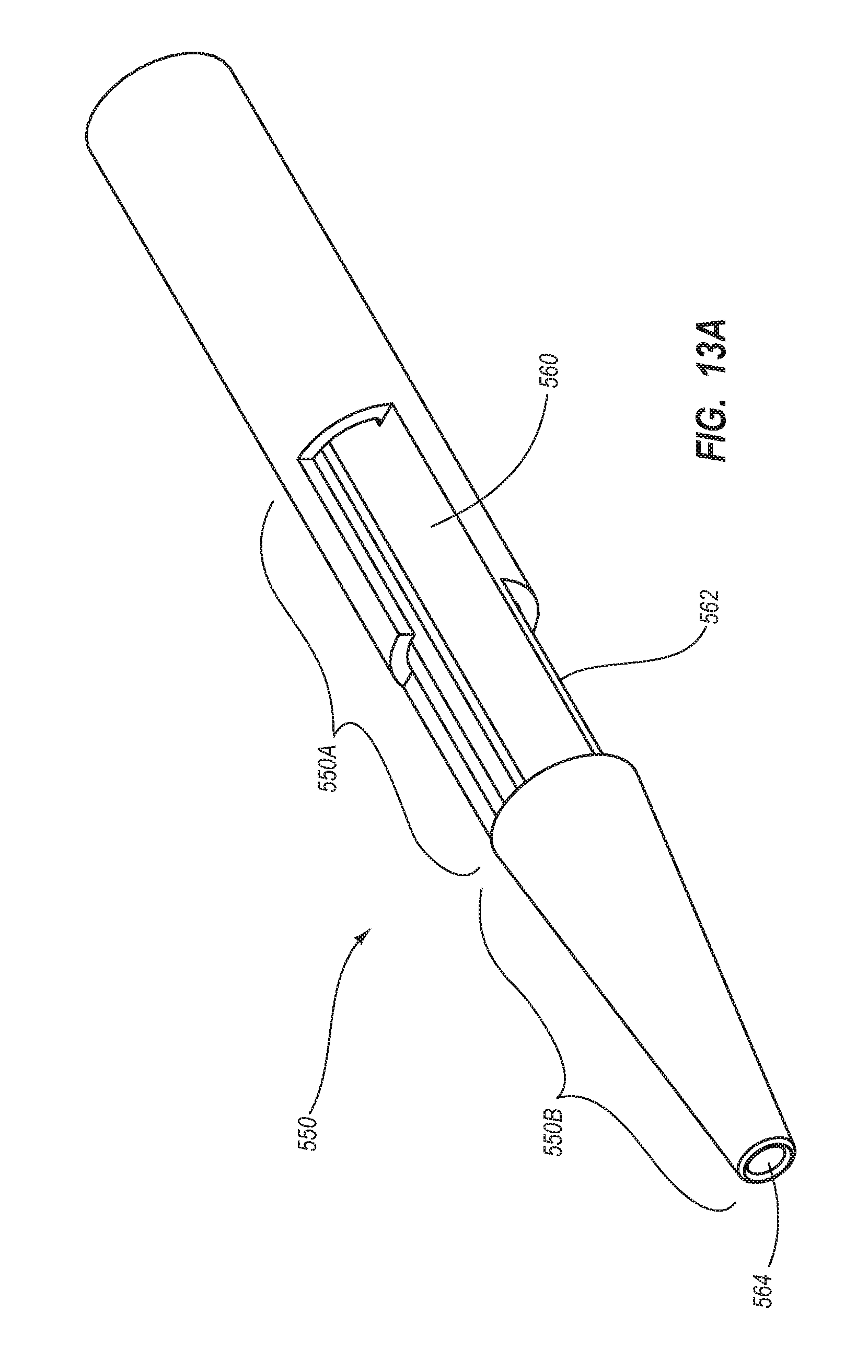
D00019
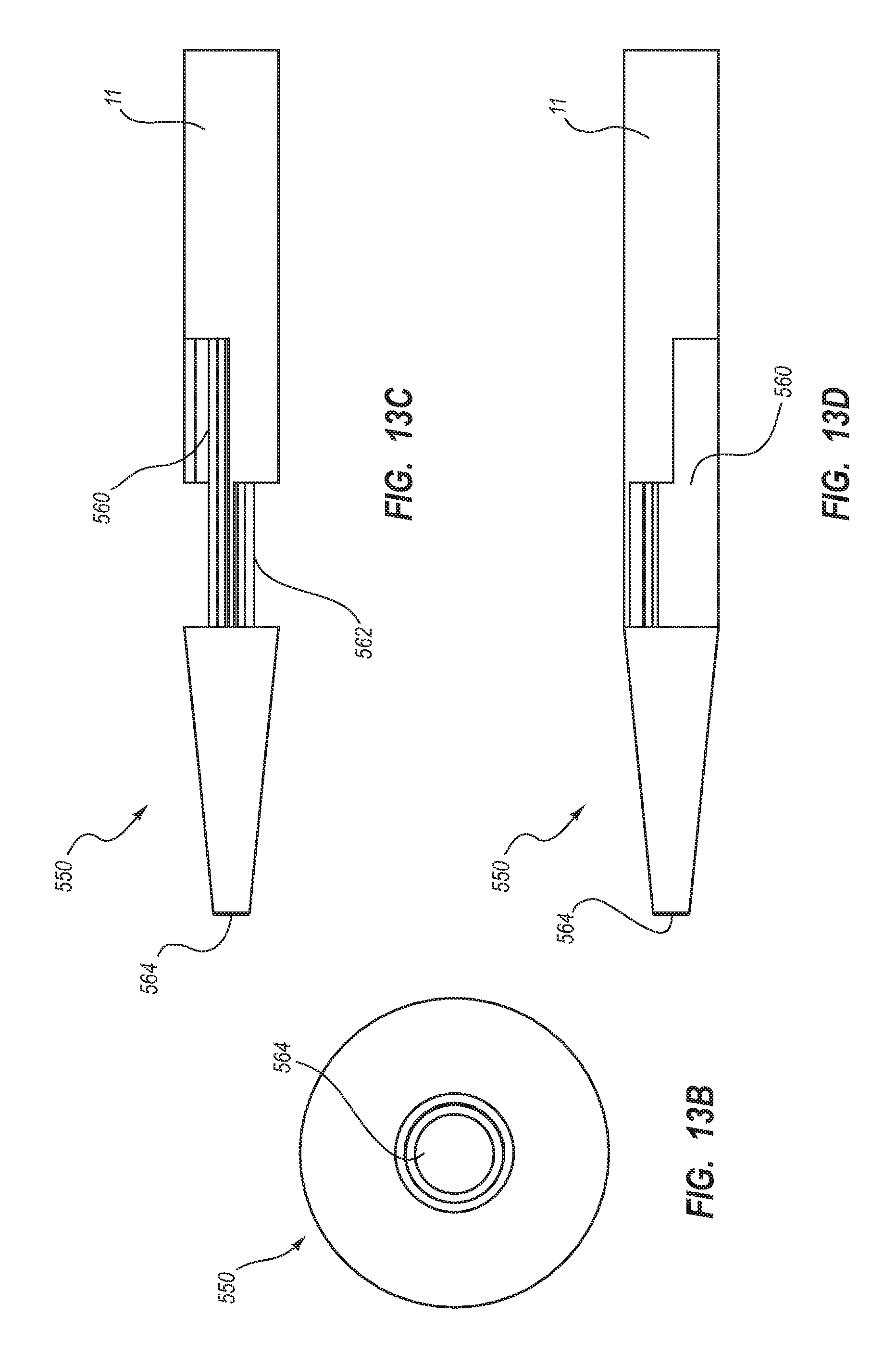
D00020

D00021

D00022
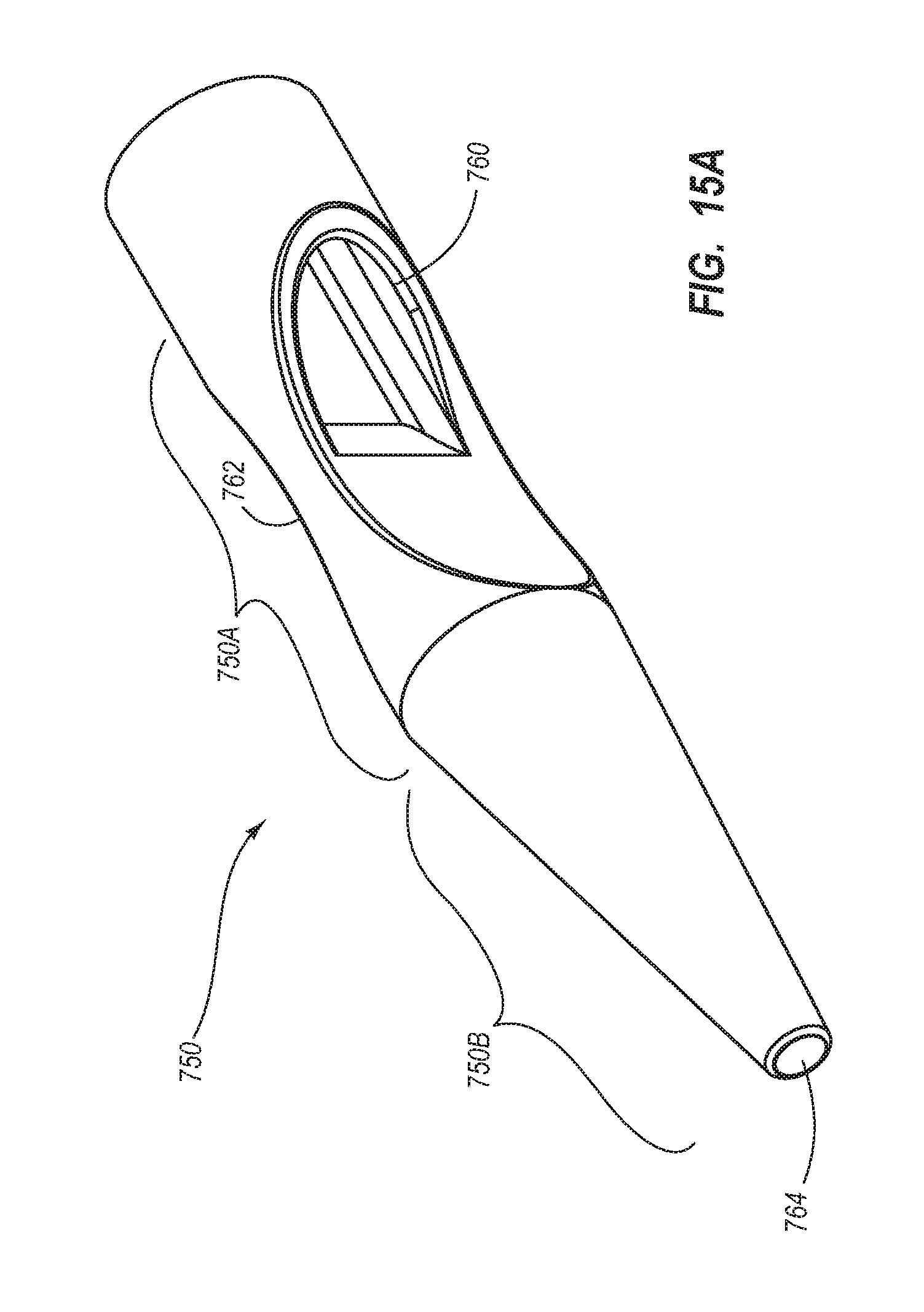
D00023
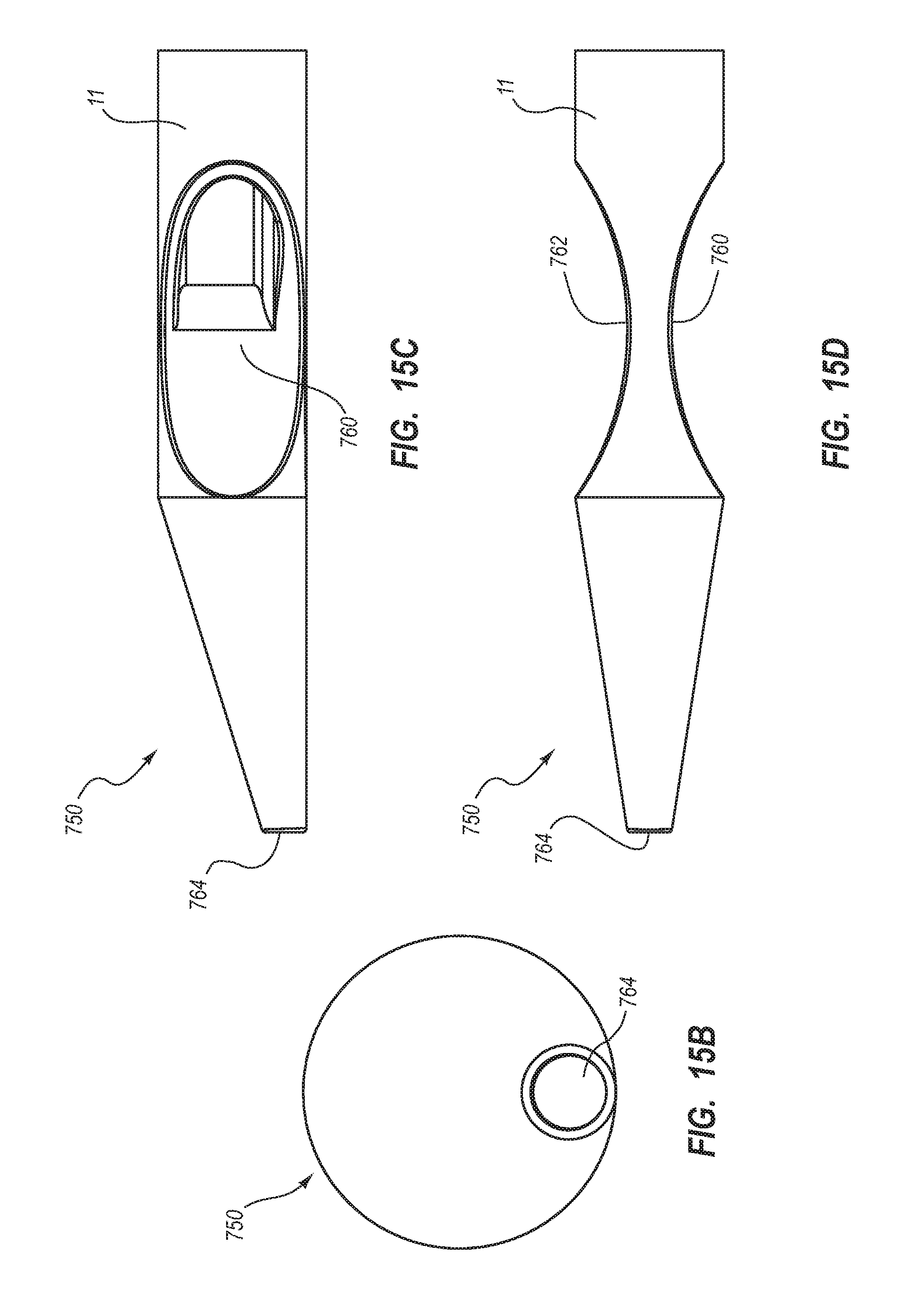
D00024
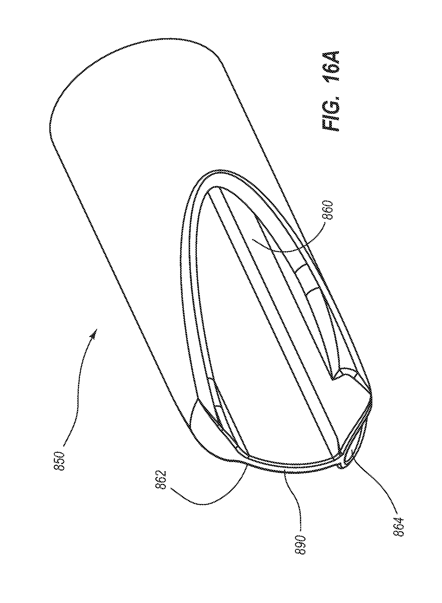
D00025

D00026

D00027
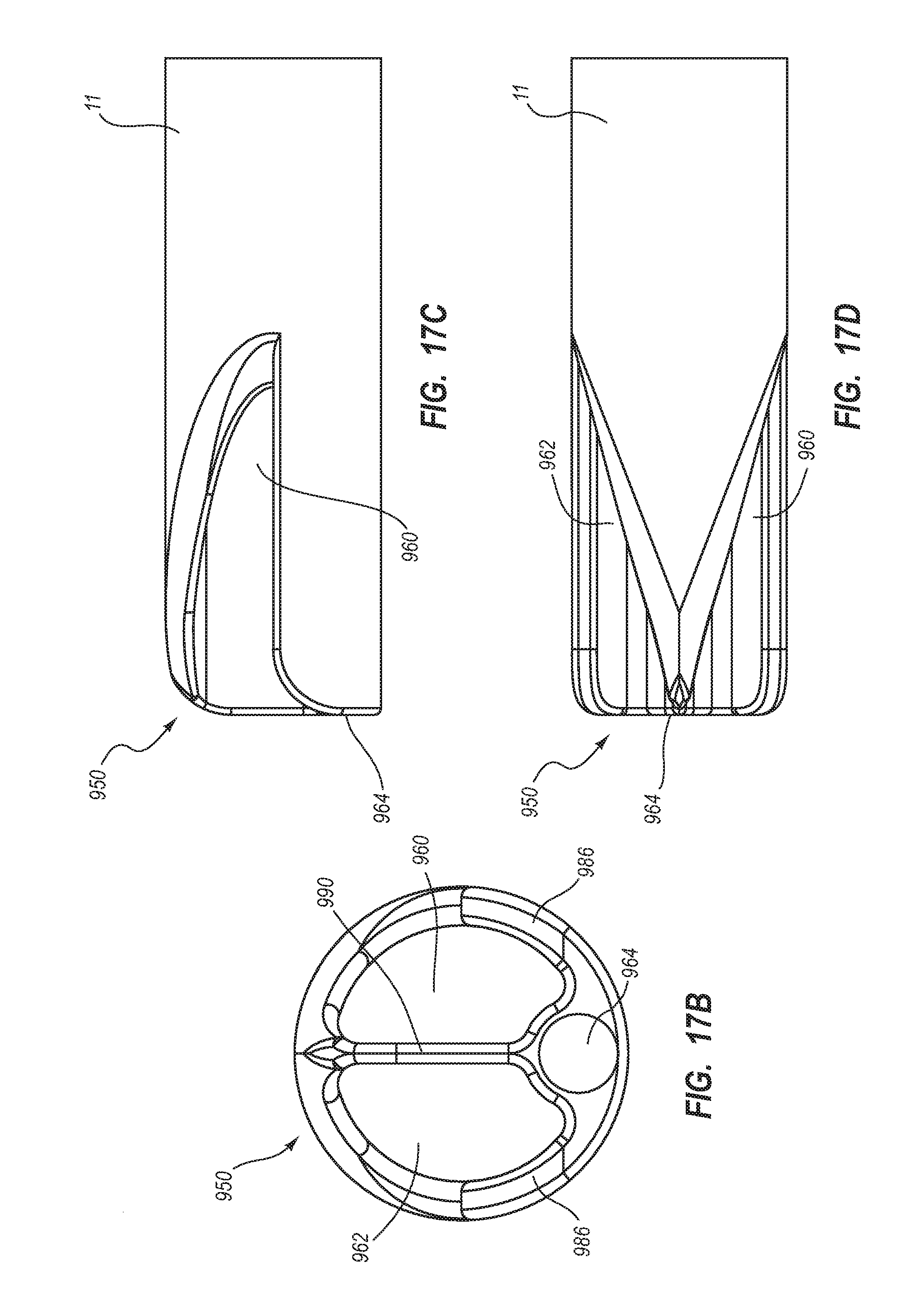
D00028
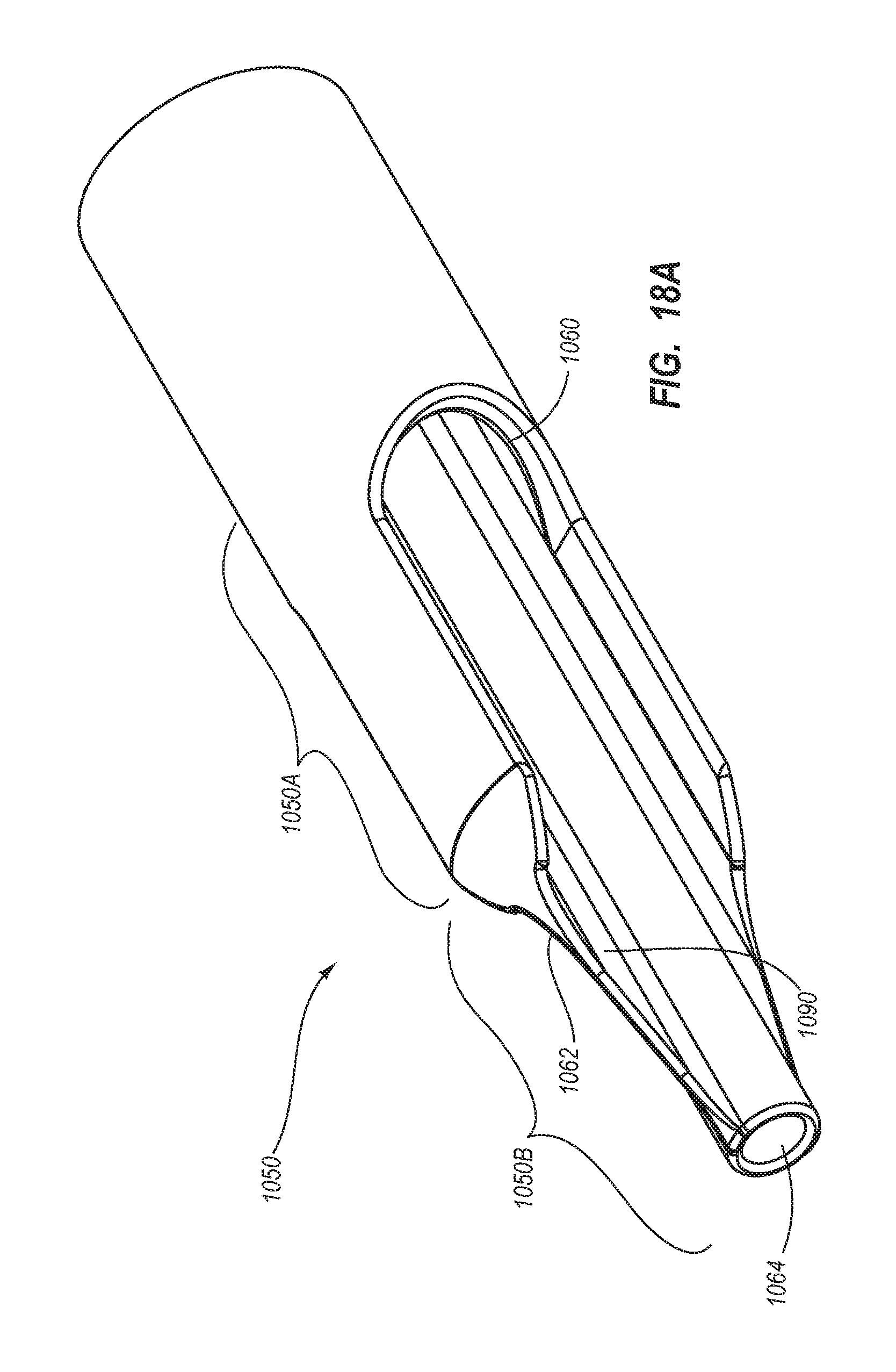
D00029
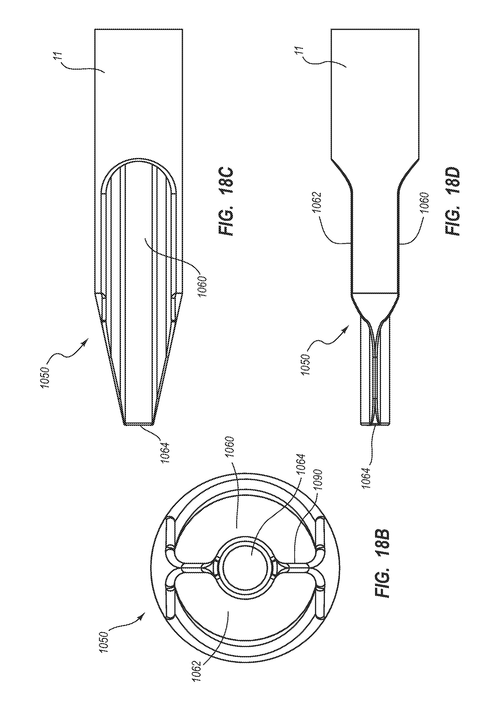
D00030
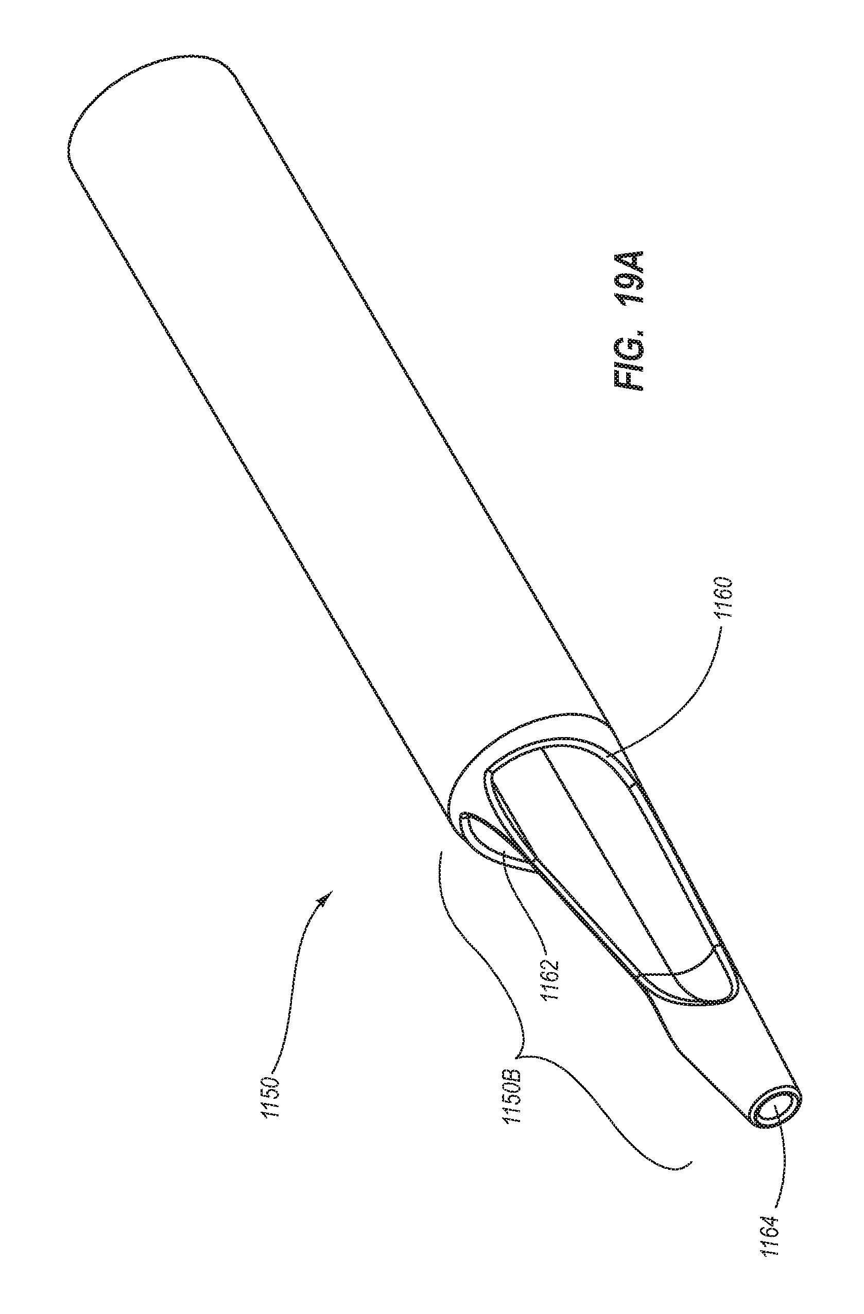
D00031

D00032
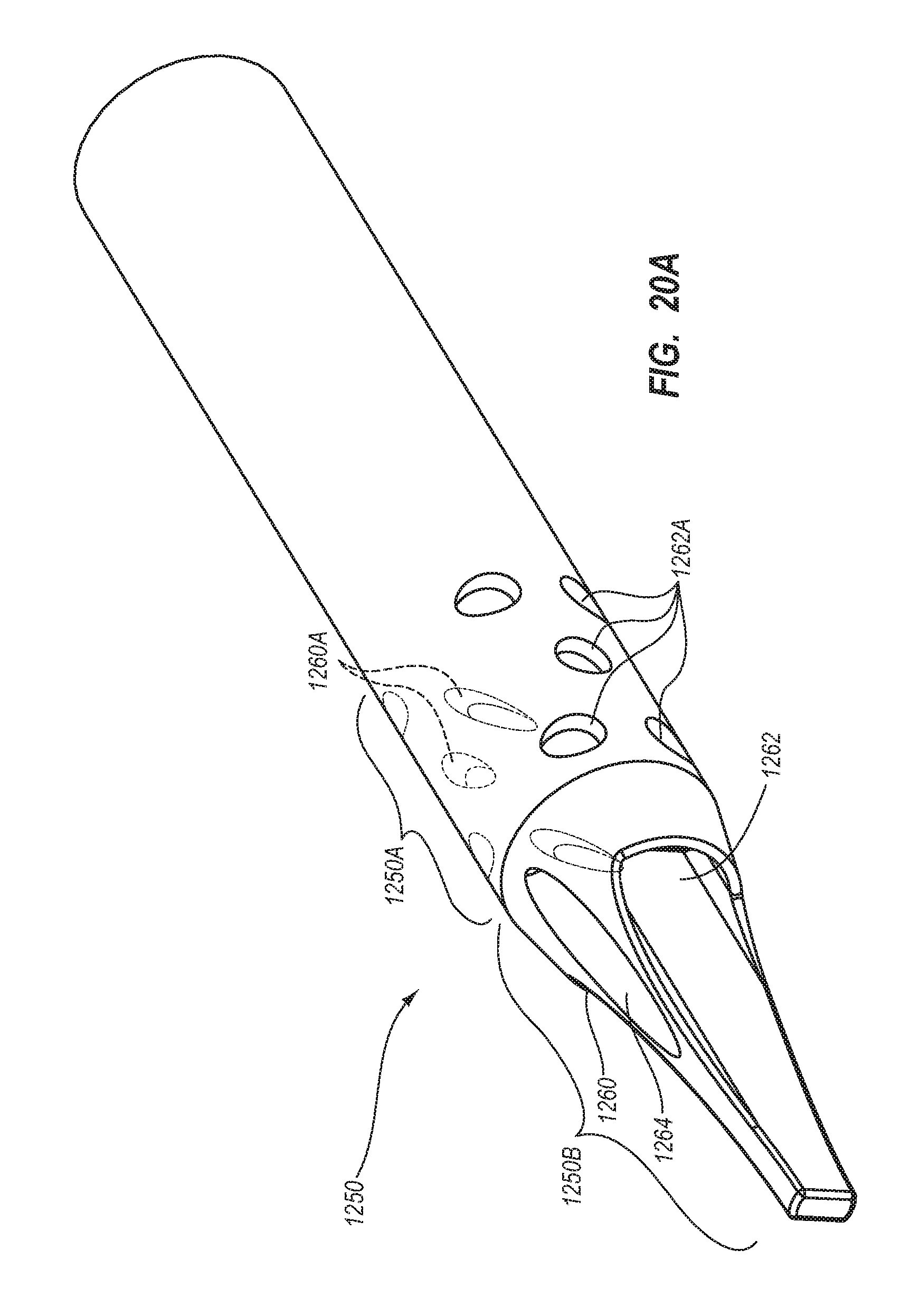
D00033

D00034
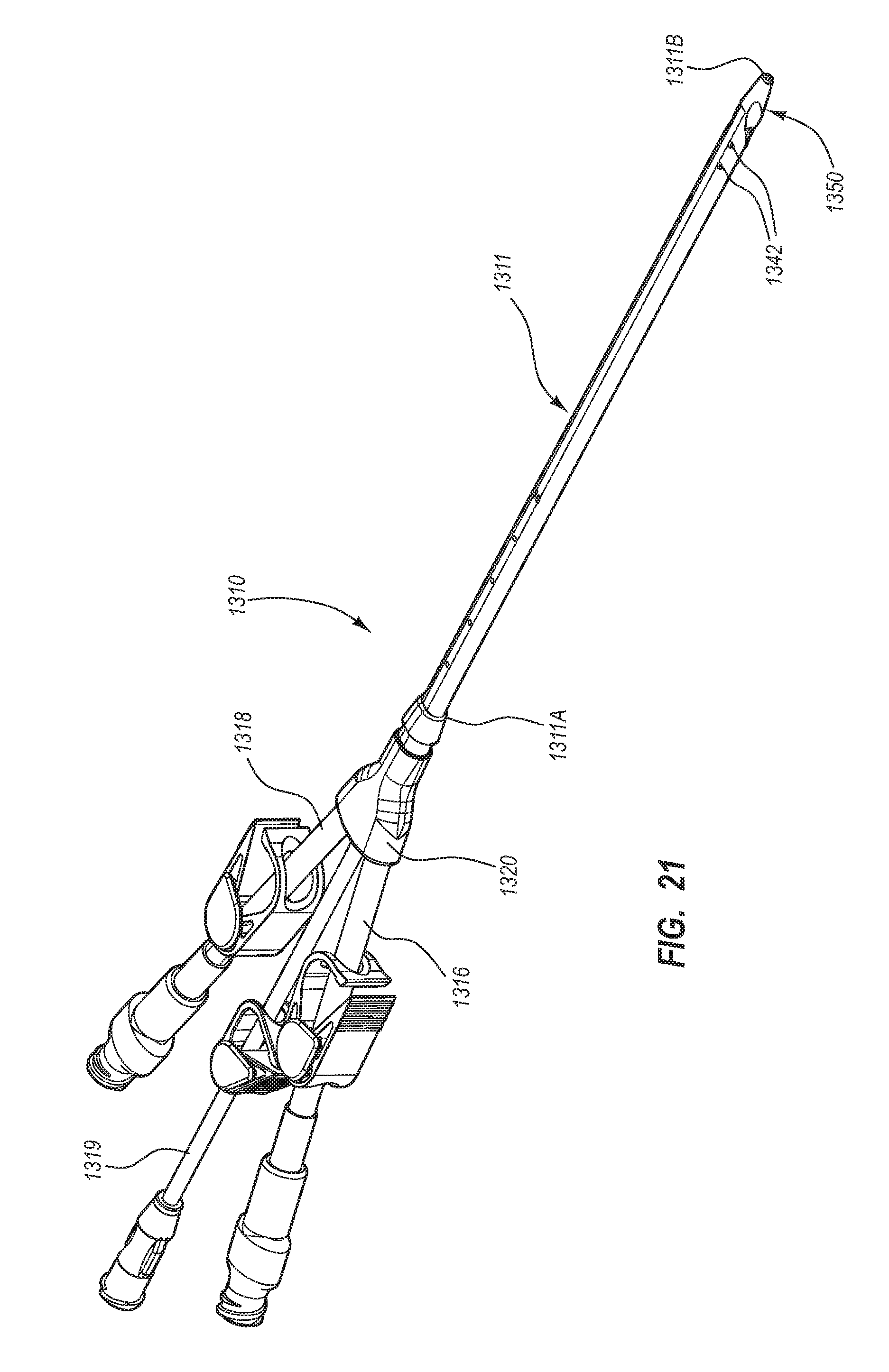
D00035
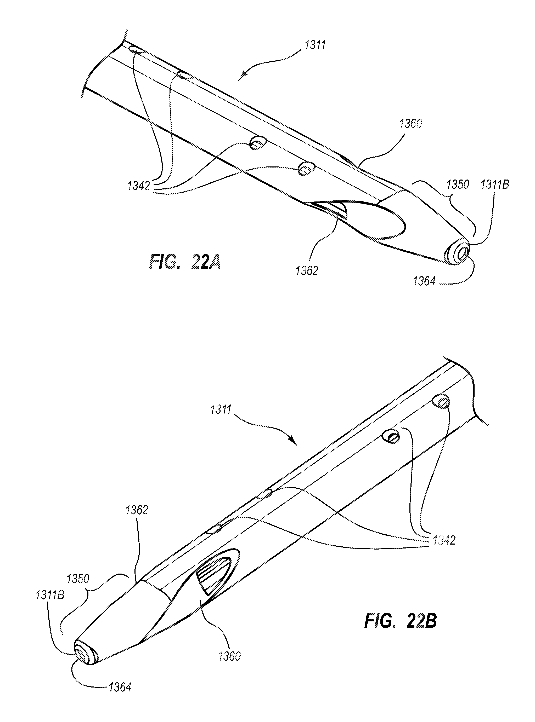
D00036

D00037

D00038

D00039
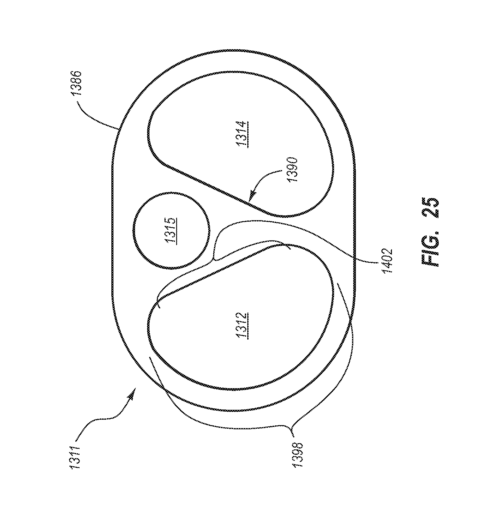
D00040
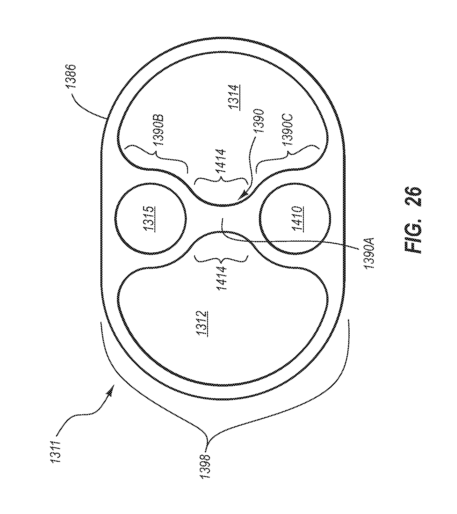
D00041
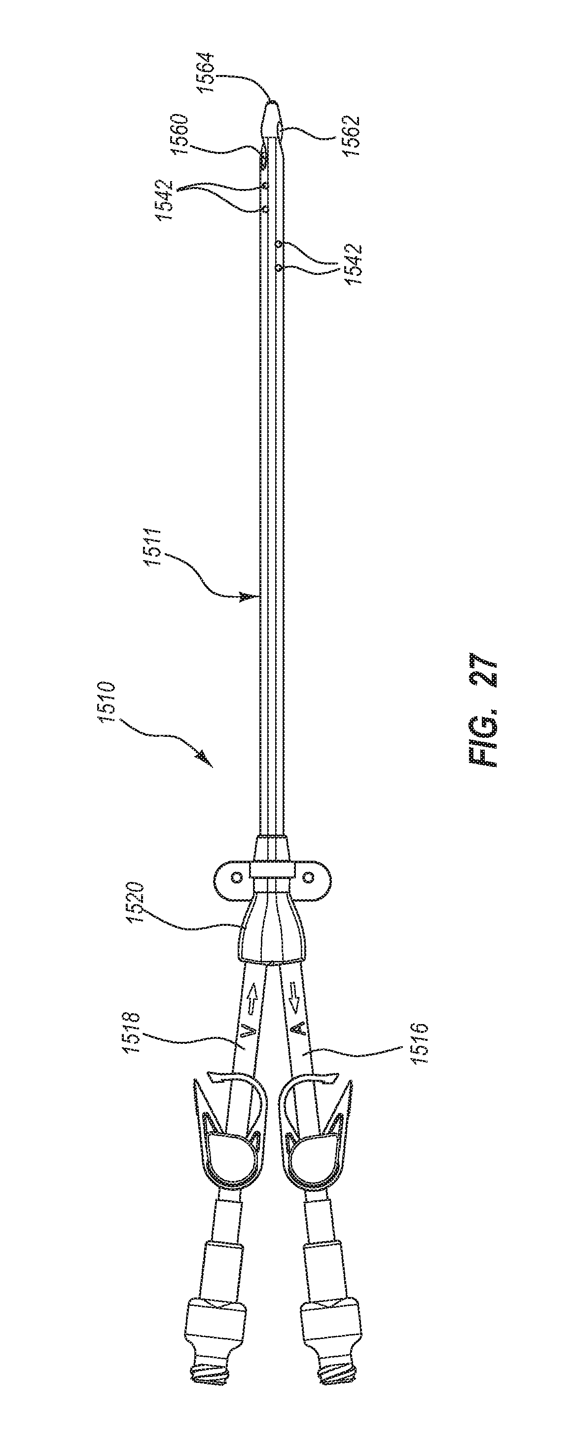
D00042

XML
uspto.report is an independent third-party trademark research tool that is not affiliated, endorsed, or sponsored by the United States Patent and Trademark Office (USPTO) or any other governmental organization. The information provided by uspto.report is based on publicly available data at the time of writing and is intended for informational purposes only.
While we strive to provide accurate and up-to-date information, we do not guarantee the accuracy, completeness, reliability, or suitability of the information displayed on this site. The use of this site is at your own risk. Any reliance you place on such information is therefore strictly at your own risk.
All official trademark data, including owner information, should be verified by visiting the official USPTO website at www.uspto.gov. This site is not intended to replace professional legal advice and should not be used as a substitute for consulting with a legal professional who is knowledgeable about trademark law.