Suturing methods and apparatuses
Nobles Dec
U.S. patent number 10,512,458 [Application Number 15/101,607] was granted by the patent office on 2019-12-24 for suturing methods and apparatuses. This patent grant is currently assigned to Med-Venture Investments, LLC. The grantee listed for this patent is Med-Venture Investments, LLC. Invention is credited to Anthony A. Nobles.


View All Diagrams
| United States Patent | 10,512,458 |
| Nobles | December 24, 2019 |
| **Please see images for: ( Certificate of Correction ) ** |
Suturing methods and apparatuses
Abstract
Suturing devices, systems, and methods used to suture biological structures. The suturing devices can be configured to place sutures into body tissue from one side of the tissue without requiring a component on an opposite side of the tissue and without requiring insertion of components into the body tissue beyond the needles and the suture.
| Inventors: | Nobles; Anthony A. (Fountain Valley, CA) | ||||||||||
|---|---|---|---|---|---|---|---|---|---|---|---|
| Applicant: |
|
||||||||||
| Assignee: | Med-Venture Investments, LLC
(Fountain Valley, CA) |
||||||||||
| Family ID: | 53274151 | ||||||||||
| Appl. No.: | 15/101,607 | ||||||||||
| Filed: | December 5, 2014 | ||||||||||
| PCT Filed: | December 05, 2014 | ||||||||||
| PCT No.: | PCT/US2014/068742 | ||||||||||
| 371(c)(1),(2),(4) Date: | June 03, 2016 | ||||||||||
| PCT Pub. No.: | WO2015/085145 | ||||||||||
| PCT Pub. Date: | June 11, 2015 |
Prior Publication Data
| Document Identifier | Publication Date | |
|---|---|---|
| US 20160302787 A1 | Oct 20, 2016 | |
Related U.S. Patent Documents
| Application Number | Filing Date | Patent Number | Issue Date | ||
|---|---|---|---|---|---|
| 61912705 | Dec 6, 2013 | ||||
| Current U.S. Class: | 1/1 |
| Current CPC Class: | A61B 17/062 (20130101); A61B 17/0469 (20130101); A61B 2017/00314 (20130101); A61B 2017/06042 (20130101) |
| Current International Class: | A61B 17/04 (20060101); A61B 17/12 (20060101); A61B 17/062 (20060101); A61B 17/06 (20060101); A61B 17/00 (20060101) |
References Cited [Referenced By]
U.S. Patent Documents
| 118683 | September 1871 | Bruce |
| 1064307 | June 1913 | Fleming |
| 1822330 | September 1931 | Ainslie |
| 1989919 | February 1935 | Everitt |
| 2473742 | June 1949 | Auzin |
| 2548602 | April 1951 | Greenburg |
| 2637290 | May 1953 | Sigoda |
| 2738790 | March 1956 | Todt, Sr. et al. |
| 2849002 | August 1958 | Oddo |
| 2945460 | July 1960 | Kagiyama |
| 3241554 | March 1966 | Coanda |
| 3292627 | December 1966 | Harautuneian |
| 3394705 | July 1968 | Abramson |
| 3664345 | May 1972 | Dabbs et al. |
| 3665926 | May 1972 | Flores |
| 3774596 | November 1973 | Cook |
| 3828790 | August 1974 | Curtiss et al. |
| 3831587 | August 1974 | Boyd |
| 3842840 | October 1974 | Schweizer |
| 3877434 | April 1975 | Samuels |
| 3882852 | May 1975 | Sinnreich |
| 3882855 | May 1975 | Schulte et al. |
| 3888117 | June 1975 | Lewis |
| 3903893 | September 1975 | Scheer |
| 3946740 | March 1976 | Bassett |
| 3946741 | March 1976 | Adair |
| 3952742 | April 1976 | Taylor |
| 3976079 | August 1976 | Samuels |
| 4052980 | October 1977 | Grams et al. |
| RE29703 | July 1978 | Fatt |
| 4107953 | August 1978 | Casillo |
| 4119100 | October 1978 | Rickett |
| 4164225 | August 1979 | Johnson et al. |
| 4230119 | October 1980 | Blum |
| 4291698 | September 1981 | Fuchs et al. |
| 4299237 | November 1981 | Foti |
| 4307722 | December 1981 | Evans |
| 4345601 | August 1982 | Fukuda |
| 4351342 | September 1982 | Wiita et al. |
| 4417532 | November 1983 | Yasukata |
| 4423725 | January 1984 | Baran et al. |
| 4447227 | May 1984 | Kotsanis |
| 4457300 | July 1984 | Budde |
| 4484580 | November 1984 | Nomoto et al. |
| 4512338 | April 1985 | Balko et al. |
| 4546759 | October 1985 | Solar |
| 4553543 | November 1985 | Amarasinghe |
| 4573966 | March 1986 | Weikl et al. |
| 4589868 | May 1986 | Dretler |
| 4610662 | September 1986 | Weikl et al. |
| 4617738 | October 1986 | Kopacz |
| 4662068 | May 1987 | Polonsky |
| 4664114 | May 1987 | Ghodsian |
| 4734094 | March 1988 | Jacob et al. |
| 4744364 | May 1988 | Kensey |
| 4750492 | June 1988 | Jacobs |
| 4771776 | September 1988 | Powell et al. |
| 4774091 | September 1988 | Yamahira et al. |
| 4794928 | January 1989 | Kletschka |
| 4795427 | January 1989 | Helzel |
| 4796629 | January 1989 | Grayzel |
| 4824436 | April 1989 | Wolinsky |
| 4827931 | May 1989 | Longmore |
| 4841888 | June 1989 | Mills et al. |
| 4861330 | August 1989 | Voss |
| 4898168 | February 1990 | Yule |
| 4923461 | May 1990 | Caspari et al. |
| 4926860 | May 1990 | Stice et al. |
| 4932956 | June 1990 | Reddy et al. |
| 4935027 | June 1990 | Yoon |
| 4954126 | September 1990 | Wallsten |
| 4957498 | September 1990 | Caspari et al. |
| 4972845 | November 1990 | Iversen et al. |
| 4981149 | January 1991 | Yoon et al. |
| 4983116 | January 1991 | Koga |
| 4984564 | January 1991 | Yuen |
| 4994070 | February 1991 | Waters |
| 5002531 | March 1991 | Bonzel |
| 5021059 | June 1991 | Kensey et al. |
| 5037433 | August 1991 | Wilk et al. |
| 5057114 | October 1991 | Wittich et al. |
| 5059201 | October 1991 | Asnis |
| 5065772 | November 1991 | Cox, Jr. |
| 5074871 | December 1991 | Groshong |
| 5078743 | January 1992 | Mikalov et al. |
| 5090958 | February 1992 | Sahota |
| 5100418 | March 1992 | Yoon et al. |
| 5104394 | April 1992 | Knoepfler |
| 5106363 | April 1992 | Nobuyoshi |
| 5108416 | April 1992 | Ryan et al. |
| 5108419 | April 1992 | Reger et al. |
| 5116305 | May 1992 | Milder et al. |
| 5122122 | June 1992 | Allgood |
| 5129883 | July 1992 | Black |
| 5133724 | July 1992 | Wilson et al. |
| 5135484 | August 1992 | Wright |
| 5160339 | November 1992 | Chen et al. |
| 5163906 | November 1992 | Ahmadi |
| 5167223 | December 1992 | Koros et al. |
| 5171251 | December 1992 | Bregen et al. |
| 5176691 | January 1993 | Pierce |
| 5192301 | March 1993 | Kamiya et al. |
| 5222508 | June 1993 | Contarini |
| 5222941 | June 1993 | Don Michael |
| 5222974 | June 1993 | Kensey et al. |
| 5224948 | July 1993 | Abe et al. |
| 5236443 | August 1993 | Sontag |
| 5242459 | September 1993 | Buelna |
| 5281234 | January 1994 | Wilk et al. |
| 5281237 | January 1994 | Gimpelson |
| 5282827 | February 1994 | Kensey et al. |
| 5286259 | February 1994 | Ganguly et al. |
| 5290249 | March 1994 | Foster et al. |
| 5291639 | March 1994 | Baum et al. |
| 5300106 | April 1994 | Dahl et al. |
| 5304184 | April 1994 | Hathaway et al. |
| 5308323 | May 1994 | Sogawa et al. |
| 5312344 | May 1994 | Grinfeld |
| 5314409 | May 1994 | Sarosiek et al. |
| 5320604 | June 1994 | Walker et al. |
| 5320632 | June 1994 | Heidmueller |
| 5330446 | July 1994 | Weldon et al. |
| 5330497 | July 1994 | Freitas et al. |
| 5331975 | July 1994 | Bonutti |
| 5336229 | August 1994 | Noda |
| 5336231 | August 1994 | Adair |
| 5337736 | August 1994 | Reddy |
| 5339801 | August 1994 | Poloyko |
| 5342306 | August 1994 | Don Michael |
| 5342385 | August 1994 | Norelli et al. |
| 5342393 | August 1994 | Stack |
| 5350399 | September 1994 | Erlebacher et al. |
| 5356382 | October 1994 | Picha et al. |
| 5364407 | November 1994 | Poll |
| 5364408 | November 1994 | Gordon |
| 5368601 | November 1994 | Sauer et al. |
| 5370618 | December 1994 | Leonhardt |
| 5370685 | December 1994 | Stevens |
| 5374275 | December 1994 | Bradley et al. |
| 5380284 | January 1995 | Don Michael |
| 5382261 | January 1995 | Palmaz |
| 5383854 | January 1995 | Safar et al. |
| 5383896 | January 1995 | Gershony et al. |
| 5383897 | January 1995 | Wholey |
| 5383905 | January 1995 | Golds et al. |
| 5389103 | February 1995 | Melzer et al. |
| 5391147 | February 1995 | Imran et al. |
| 5391174 | February 1995 | Weston |
| 5395383 | March 1995 | Adams et al. |
| 5397325 | March 1995 | Badia et al. |
| 5403329 | April 1995 | Hinchcliffe |
| 5403331 | April 1995 | Chesterfield et al. |
| 5403341 | April 1995 | Solar |
| 5405322 | April 1995 | Lennox et al. |
| 5405354 | April 1995 | Sarrett |
| 5417699 | May 1995 | Klein et al. |
| 5417700 | May 1995 | Egan |
| 5423777 | June 1995 | Tajiri et al. |
| 5423837 | June 1995 | Mericle et al. |
| 5425708 | June 1995 | Nasu |
| 5425737 | June 1995 | Burbank et al. |
| 5425744 | June 1995 | Fagan et al. |
| 5429118 | July 1995 | Cole et al. |
| 5431666 | July 1995 | Sauer et al. |
| 5439470 | August 1995 | Li |
| 5445167 | August 1995 | Yoon et al. |
| 5447515 | September 1995 | Robicsek |
| 5452513 | September 1995 | Zinnbauer et al. |
| 5454823 | October 1995 | Richardson et al. |
| 5458574 | October 1995 | Machold et al. |
| 5458609 | October 1995 | Gordon et al. |
| 5462560 | October 1995 | Stevens |
| 5462561 | October 1995 | Voda |
| 5470338 | November 1995 | Whitefield et al. |
| 5474572 | December 1995 | Hayburst |
| 5476469 | December 1995 | Hathaway et al. |
| 5476470 | December 1995 | Fitzgibbons, Jr. |
| 5496332 | March 1996 | Sierra et al. |
| 5499991 | March 1996 | Garman et al. |
| 5501691 | March 1996 | Goldrath |
| 5507754 | April 1996 | Green et al. |
| 5507755 | April 1996 | Gresl et al. |
| 5514159 | May 1996 | Matula et al. |
| 5520609 | May 1996 | Moll et al. |
| 5520702 | May 1996 | Sauer et al. |
| 5522961 | June 1996 | Leonhardt |
| 5527321 | June 1996 | Hinchliffe |
| 5527322 | June 1996 | Klein et al. |
| 5527338 | June 1996 | Purdy |
| 5540658 | July 1996 | Evans et al. |
| 5540704 | July 1996 | Gordon et al. |
| 5545170 | August 1996 | Hart |
| 5549633 | August 1996 | Evans et al. |
| 5558642 | September 1996 | Schweich et al. |
| 5558644 | September 1996 | Boyd et al. |
| RE35352 | October 1996 | Peters |
| 5562686 | October 1996 | Sauer et al. |
| 5562688 | October 1996 | Riza |
| 5565122 | October 1996 | Zinnbauer et al. |
| 5571090 | November 1996 | Sherts |
| 5573540 | November 1996 | Yoon |
| 5584835 | December 1996 | Greenfield |
| 5584861 | December 1996 | Swain et al. |
| 5591195 | January 1997 | Taheri et al. |
| 5593422 | January 1997 | Muijs Van de Moer et al. |
| 5599307 | February 1997 | Bacher et al. |
| 5603718 | February 1997 | Xu |
| 5613974 | March 1997 | Andreas et al. |
| 5613975 | March 1997 | Christy |
| 5626590 | May 1997 | Wilk |
| 5630833 | May 1997 | Katsaros et al. |
| 5632751 | May 1997 | Piraka |
| 5632752 | May 1997 | Buelna |
| 5634936 | June 1997 | Linden et al. |
| 5637097 | June 1997 | Yoon |
| 5643289 | July 1997 | Sauer et al. |
| 5645553 | July 1997 | Kolesa et al. |
| 5662663 | September 1997 | Shallman |
| 5669917 | September 1997 | Sauer et al. |
| 5669971 | September 1997 | Bok et al. |
| 5674198 | October 1997 | Leone |
| 5681296 | October 1997 | Ishida |
| 5681351 | October 1997 | Jamiolkowski et al. |
| 5688245 | November 1997 | Runge |
| 5690674 | November 1997 | Diaz |
| 5695468 | December 1997 | Lafontaine et al. |
| 5695504 | December 1997 | Gifford, III et al. |
| 5697905 | December 1997 | D'Ambrosio |
| 5700273 | December 1997 | Buelna et al. |
| 5700277 | December 1997 | Nash et al. |
| 5707379 | January 1998 | Fleenor et al. |
| 5709693 | January 1998 | Taylor |
| 5716329 | February 1998 | Dieter |
| 5720757 | February 1998 | Hathaway et al. |
| 5722983 | March 1998 | Van Der Weegen |
| 5728109 | March 1998 | Schulze et al. |
| 5738629 | April 1998 | Moll et al. |
| 5743852 | April 1998 | Johnson |
| 5746753 | May 1998 | Sullivan et al. |
| 5749883 | May 1998 | Halpern |
| 5759188 | June 1998 | Yoon |
| 5766183 | June 1998 | Sauer |
| 5766220 | June 1998 | Moenning |
| 5769870 | June 1998 | Salahieh et al. |
| 5779719 | July 1998 | Klein et al. |
| 5792152 | August 1998 | Klein et al. |
| 5792153 | August 1998 | Swain et al. |
| 5795289 | August 1998 | Wyttenbach |
| 5795325 | August 1998 | Valley et al. |
| 5797948 | August 1998 | Dunham |
| 5797960 | August 1998 | Stevens et al. |
| 5810757 | September 1998 | Sweezer et al. |
| 5810849 | September 1998 | Kontos |
| 5810850 | September 1998 | Hathaway et al. |
| 5817108 | October 1998 | Poncet |
| 5817110 | October 1998 | Kronner |
| 5820631 | October 1998 | Nobles |
| 5836955 | November 1998 | Buelna et al. |
| 5843100 | December 1998 | Meade |
| 5846251 | December 1998 | Hart |
| 5846253 | December 1998 | Buelna et al. |
| 5853399 | December 1998 | Sasaki |
| 5853422 | December 1998 | Huebsch et al. |
| 5855585 | January 1999 | Kontos |
| 5860990 | January 1999 | Nobles et al. |
| 5860991 | January 1999 | Klein et al. |
| 5860992 | January 1999 | Daniel et al. |
| 5860997 | January 1999 | Bonutti |
| 5861003 | January 1999 | Latson et al. |
| 5865729 | February 1999 | Holman et al. |
| 5868708 | February 1999 | Hart et al. |
| 5868762 | February 1999 | Cragg et al. |
| 5871320 | February 1999 | Kovac |
| 5871537 | February 1999 | Holman et al. |
| 5876411 | March 1999 | Kontos |
| 5899921 | May 1999 | Caspari et al. |
| 5902311 | May 1999 | Andreas et al. |
| 5902321 | May 1999 | Caspari et al. |
| 5906577 | May 1999 | Beane et al. |
| 5908428 | June 1999 | Scirica et al. |
| 5919200 | July 1999 | Stambaugh et al. |
| 5919208 | July 1999 | Valenti |
| 5928192 | July 1999 | Maahs |
| 5931844 | August 1999 | Thompson et al. |
| 5935098 | August 1999 | Blaisdell et al. |
| 5935149 | August 1999 | Ek |
| 5944730 | August 1999 | Nobles et al. |
| 5951588 | September 1999 | Moenning |
| 5951590 | September 1999 | Goldfarb |
| 5954732 | September 1999 | Hart et al. |
| 5967970 | October 1999 | Cowan et al. |
| 5971983 | October 1999 | Lesh |
| 5972005 | October 1999 | Stalker et al. |
| 5980539 | November 1999 | Kontos |
| 5993466 | November 1999 | Yoon |
| 5997555 | December 1999 | Kontos |
| 6001109 | December 1999 | Kontos |
| 6004337 | December 1999 | Kieturakis et al. |
| 6010530 | January 2000 | Goicoechea |
| 6015428 | January 2000 | Pagedas |
| 6024747 | February 2000 | Kontos |
| 6033430 | March 2000 | Bonutti |
| 6036699 | March 2000 | Andreas et al. |
| 6059800 | May 2000 | Hart et al. |
| 6066160 | May 2000 | Colvin et al. |
| 6068648 | May 2000 | Cole et al. |
| 6071271 | June 2000 | Baker et al. |
| 6077277 | June 2000 | Mollenauer et al. |
| 6086608 | July 2000 | Ek et al. |
| 6099553 | August 2000 | Hart et al. |
| 6110185 | August 2000 | Barra et al. |
| 6113580 | September 2000 | Dolisi |
| 6117144 | September 2000 | Nobles et al. |
| 6126677 | October 2000 | Ganaja et al. |
| 6136010 | October 2000 | Modesitt et al. |
| 6143015 | November 2000 | Nobles |
| 6159234 | December 2000 | Bonutti et al. |
| 6171319 | January 2001 | Nobles et al. |
| 6174324 | January 2001 | Egan et al. |
| 6187026 | February 2001 | Devlin et al. |
| 6190396 | February 2001 | Whitin et al. |
| 6200329 | March 2001 | Fung et al. |
| 6203565 | March 2001 | Bonutti et al. |
| 6210429 | April 2001 | Vardi et al. |
| 6217591 | April 2001 | Egan et al. |
| 6241699 | June 2001 | Suresh et al. |
| 6245079 | June 2001 | Nobles et al. |
| 6245080 | June 2001 | Levinson |
| 6248121 | June 2001 | Nobles |
| 6280460 | August 2001 | Bolduc et al. |
| 6290674 | September 2001 | Roue et al. |
| 6332889 | December 2001 | Sancoff et al. |
| 6348059 | February 2002 | Hathaway et al. |
| 6352543 | March 2002 | Cole et al. |
| 6383208 | May 2002 | Sancoff et al. |
| 6395015 | May 2002 | Borst et al. |
| 6409739 | June 2002 | Nobles et al. |
| 6432115 | August 2002 | Mollenauer et al. |
| 6468293 | October 2002 | Bonutti et al. |
| 6508777 | January 2003 | Macoviak et al. |
| 6527785 | March 2003 | Sancoff et al. |
| 6533795 | March 2003 | Tran et al. |
| 6537299 | March 2003 | Hogendijk et al. |
| 6547725 | April 2003 | Paolitto et al. |
| 6547760 | April 2003 | Samson et al. |
| 6551331 | April 2003 | Nobles et al. |
| 6562052 | May 2003 | Nobles et al. |
| 6585689 | July 2003 | Macoviak et al. |
| 6663643 | December 2003 | Field et al. |
| 6679895 | January 2004 | Sancoff et al. |
| 6682540 | January 2004 | Sancoff et al. |
| 6716243 | April 2004 | Colvin et al. |
| 6726651 | April 2004 | Robinson et al. |
| 6733509 | May 2004 | Nobles et al. |
| 6767352 | July 2004 | Field et al. |
| 6770076 | August 2004 | Foerster |
| 6770084 | August 2004 | Bain et al. |
| 6786913 | September 2004 | Sancoff |
| 6978176 | January 2005 | Lattouf |
| 6855157 | February 2005 | Foerster et al. |
| 6893448 | May 2005 | O'Quinn et al. |
| 6911034 | June 2005 | Nobles et al. |
| 6913600 | July 2005 | Valley et al. |
| 6936057 | August 2005 | Nobles |
| 7004952 | February 2006 | Nobles et al. |
| 7083630 | August 2006 | DeVries et al. |
| 7083638 | August 2006 | Foerster |
| 7090686 | August 2006 | Nobles et al. |
| 7090690 | August 2006 | Foerster et al. |
| 7118583 | October 2006 | O'Quinn et al. |
| 7160309 | January 2007 | Voss |
| 7172595 | February 2007 | Goble |
| 7220266 | May 2007 | Gambale |
| 7232446 | June 2007 | Farris |
| 7235086 | June 2007 | Sauer et al. |
| 7326221 | February 2008 | Sakamoto et al. |
| 7329272 | February 2008 | Burkhart et al. |
| 7338502 | March 2008 | Rosenblatt |
| 7381210 | June 2008 | Zarbatany et al. |
| 7399304 | July 2008 | Gambale et al. |
| 7435251 | October 2008 | Green |
| 7449024 | November 2008 | Stafford |
| 7491217 | February 2009 | Hendren |
| 7601161 | October 2009 | Nobles et al. |
| 7628797 | December 2009 | Tieu et al. |
| 7635386 | December 2009 | Gammie |
| 7637926 | December 2009 | Foerster et al. |
| 7722629 | May 2010 | Chambers |
| 7803167 | September 2010 | Nobles et al. |
| 7842051 | November 2010 | Dana et al. |
| 7846181 | December 2010 | Schwartz et al. |
| 7879072 | February 2011 | Bonutti et al. |
| 7905892 | March 2011 | Nobles et al. |
| 7918867 | April 2011 | Dana et al. |
| 7931641 | April 2011 | Chang et al. |
| 7993368 | August 2011 | Gambale et al. |
| 8075573 | December 2011 | Gambale et al. |
| 8083754 | December 2011 | Pantages et al. |
| 8105355 | January 2012 | Page et al. |
| 8197497 | June 2012 | Nobles et al. |
| 8246636 | August 2012 | Nobles et al. |
| 8258005 | August 2012 | Findlay, III et al. |
| 8282659 | October 2012 | Oren et al. |
| 8287556 | October 2012 | Gilkey et al. |
| 8298291 | October 2012 | Ewers et al. |
| 8303622 | November 2012 | Alkhatib |
| 8348962 | January 2013 | Nobles et al. |
| 8372089 | February 2013 | Nobles et al. |
| 8398676 | March 2013 | Roorda et al. |
| 8469975 | June 2013 | Nobles et al. |
| 8496676 | July 2013 | Nobles et al. |
| 8500776 | August 2013 | Ebner |
| 8540736 | September 2013 | Gaynor et al. |
| 8568427 | October 2013 | Nobles et al. |
| 8623036 | January 2014 | Harrison et al. |
| 8728105 | May 2014 | Aguirre |
| 8758370 | June 2014 | Shikhman et al. |
| 8771296 | July 2014 | Nobles et al. |
| 9131938 | September 2015 | Nobles et al. |
| 9326764 | May 2016 | Nobles et al. |
| 9332976 | May 2016 | Yribarren |
| 9364238 | June 2016 | Bakos et al. |
| 9398907 | July 2016 | Nobles et al. |
| 9402605 | August 2016 | Viola |
| 10178993 | January 2019 | Nobles et al. |
| 10182802 | January 2019 | Nobles et al. |
| 10194902 | February 2019 | Nobles et al. |
| 2001/0031973 | October 2001 | Nobles et al. |
| 2002/0013601 | January 2002 | Nobles et al. |
| 2002/0045908 | April 2002 | Nobles et al. |
| 2002/0049453 | April 2002 | Nobles et al. |
| 2002/0087178 | July 2002 | Nobles et al. |
| 2002/0096183 | July 2002 | Stevens et al. |
| 2002/0111653 | August 2002 | Foerster |
| 2002/0128598 | September 2002 | Nobles |
| 2002/0169475 | November 2002 | Gainor et al. |
| 2002/0183787 | December 2002 | Wahr et al. |
| 2003/0078601 | April 2003 | Skikhman et al. |
| 2003/0114863 | June 2003 | Field et al. |
| 2003/0144673 | July 2003 | Onuki et al. |
| 2003/0204205 | October 2003 | Sauer et al. |
| 2003/0208209 | November 2003 | Gambale et al. |
| 2003/0220667 | November 2003 | van der Burg et al. |
| 2004/0044365 | March 2004 | Bachman |
| 2004/0059351 | March 2004 | Eigler et al. |
| 2004/0102797 | May 2004 | Golden et al. |
| 2004/0153116 | August 2004 | Nobles |
| 2004/0236356 | November 2004 | Rioux et al. |
| 2004/0260298 | December 2004 | Kaiseer et al. |
| 2005/0033361 | February 2005 | Galdonik et al. |
| 2005/0070923 | March 2005 | McIntosh |
| 2005/0149066 | July 2005 | Stafford |
| 2005/0187575 | August 2005 | Hallbeck et al. |
| 2005/0203564 | September 2005 | Nobles |
| 2005/0261708 | November 2005 | Pasricha et al. |
| 2005/0261710 | November 2005 | Sakamoto et al. |
| 2005/0277986 | December 2005 | Foerster et al. |
| 2006/0052813 | March 2006 | Nobles |
| 2006/0064113 | March 2006 | Nakao |
| 2006/0064115 | March 2006 | Allen et al. |
| 2006/0069397 | March 2006 | Nobles et al. |
| 2006/0074484 | April 2006 | Huber |
| 2006/0095052 | May 2006 | Chambers |
| 2006/0195120 | August 2006 | Nobles et al. |
| 2006/0248691 | November 2006 | Rosemann |
| 2006/0265010 | November 2006 | Paraschac et al. |
| 2006/0282088 | December 2006 | Ryan |
| 2006/0282102 | December 2006 | Nobles et al. |
| 2006/0287657 | December 2006 | Bachman |
| 2007/0010829 | January 2007 | Nobles et al. |
| 2007/0043385 | February 2007 | Nobles et al. |
| 2007/0106310 | May 2007 | Goldin et al. |
| 2007/0118151 | May 2007 | Davidson |
| 2007/0142846 | June 2007 | Catanese, III et al. |
| 2007/0213757 | September 2007 | Boraiah |
| 2007/0219630 | September 2007 | Chu |
| 2007/0276413 | November 2007 | Nobles |
| 2007/0276414 | November 2007 | Nobles |
| 2008/0033459 | February 2008 | Shafi et al. |
| 2008/0065145 | March 2008 | Carpenter |
| 2008/0077162 | March 2008 | Domingo |
| 2008/0114384 | May 2008 | Chang et al. |
| 2008/0188873 | August 2008 | Speziali |
| 2008/0228201 | September 2008 | Zarbatany |
| 2008/0269786 | October 2008 | Nobles et al. |
| 2008/0269788 | October 2008 | Phillips |
| 2009/0036906 | February 2009 | Stafford |
| 2009/0048615 | February 2009 | McIntosh |
| 2009/0099410 | April 2009 | De Marchena |
| 2009/0105729 | April 2009 | Zentgraf |
| 2009/0105751 | April 2009 | Zentgraf |
| 2009/0118726 | May 2009 | Auth et al. |
| 2009/0125042 | May 2009 | Mouw |
| 2009/0287183 | November 2009 | Bishop et al. |
| 2009/0312772 | December 2009 | Chu |
| 2009/0312783 | December 2009 | Whayne et al. |
| 2009/0312789 | December 2009 | Kassab et al. |
| 2010/0016870 | January 2010 | Campbell |
| 2010/0030242 | February 2010 | Nobles et al. |
| 2010/0042147 | February 2010 | Janovsky et al. |
| 2010/0063586 | March 2010 | Hasenkam et al. |
| 2010/0087838 | April 2010 | Nobles et al. |
| 2010/0094314 | April 2010 | Hernlund et al. |
| 2010/0100167 | April 2010 | Bortlein et al. |
| 2010/0179585 | July 2010 | Carpenter et al. |
| 2010/0210899 | August 2010 | Schankereli |
| 2011/0190793 | August 2011 | Nobles et al. |
| 2011/0202077 | August 2011 | Chin et al. |
| 2011/0224720 | September 2011 | Kassab et al. |
| 2011/0251627 | October 2011 | Hamilton et al. |
| 2012/0016384 | January 2012 | Wilke et al. |
| 2012/0035628 | February 2012 | Aguirre et al. |
| 2012/0059398 | March 2012 | Pate et al. |
| 2012/0143222 | June 2012 | Dravis et al. |
| 2012/0165838 | June 2012 | Kobylewski et al. |
| 2013/0103056 | April 2013 | Chu |
| 2013/0261645 | October 2013 | Nobles et al. |
| 2013/0324800 | December 2013 | Cahill |
| 2014/0148825 | May 2014 | Nobles et al. |
| 2014/0303654 | October 2014 | Nobles et al. |
| 2014/0309670 | October 2014 | Bakos et al. |
| 2014/0379006 | December 2014 | Sutherland et al. |
| 2015/0126815 | May 2015 | Nobles |
| 2015/0359531 | December 2015 | Sauer |
| 2015/0374351 | December 2015 | Nobles et al. |
| 2016/0007998 | January 2016 | Nobles et al. |
| 2016/0151064 | June 2016 | Nobles |
| 2016/0302787 | October 2016 | Nobles |
| 2017/0035425 | February 2017 | Fegelman et al. |
| 2017/0042534 | February 2017 | Nobles |
| 2017/0049451 | February 2017 | Hausen |
| 2017/0296168 | April 2017 | Nobles et al. |
| 2017/0128059 | May 2017 | Coe et al. |
| 2017/0245853 | August 2017 | Nobles |
| 2017/0303915 | October 2017 | Nobles |
| 2019/0029672 | January 2019 | Nobles et al. |
| 2006251579 | Nov 2006 | AU | |||
| 101495049 | Dec 2010 | CN | |||
| 101257852 | Aug 2011 | CN | |||
| 102892359 | Jan 2013 | CN | |||
| 29 01 701 | Jul 1980 | DE | |||
| 0 241 038 | Oct 1987 | EP | |||
| 0 544 485 | Jun 1993 | EP | |||
| 0839 550 | May 1998 | EP | |||
| 0 894 475 | Feb 1999 | EP | |||
| 1 196 093 | Apr 2002 | EP | |||
| 1 303 218 | Apr 2003 | EP | |||
| 0 941 698 | May 2005 | EP | |||
| 0 983 027 | Dec 2005 | EP | |||
| 1 852 071 | Nov 2007 | EP | |||
| 1 987 779 | Nov 2008 | EP | |||
| 2 572 649 | Mar 2013 | EP | |||
| 2 701 401 | Aug 1994 | FR | |||
| A 9507398 | Jul 1997 | JP | |||
| 09-266910 | Oct 1997 | JP | |||
| H10-43192 | Feb 1998 | JP | |||
| 2001-524864 | Dec 2001 | JP | |||
| 2003-139113 | May 2003 | JP | |||
| 2003-225241 | Aug 2003 | JP | |||
| 2007-503870 | Mar 2007 | JP | |||
| 2008-514305 | May 2008 | JP | |||
| 2008-541857 | Nov 2008 | JP | |||
| 2008-546454 | Dec 2008 | JP | |||
| 2009-261960 | Nov 2009 | JP | |||
| 2010-522625 | Jul 2010 | JP | |||
| 2011-067251 | Apr 2011 | JP | |||
| 5848125 | Dec 2015 | JP | |||
| 1560129 | Apr 1990 | SU | |||
| WO 92/05828 | Apr 1992 | WO | |||
| WO 93/01750 | Feb 1993 | WO | |||
| WO 93/07800 | Apr 1993 | WO | |||
| WO 95/12429 | May 1995 | WO | |||
| WO 95/17127 | Jun 1995 | WO | |||
| WO 95/25468 | Sep 1995 | WO | |||
| WO 95/25470 | Sep 1995 | WO | |||
| WO 96/03083 | Feb 1996 | WO | |||
| WO 96/29012 | Sep 1996 | WO | |||
| WO 96/40347 | Dec 1996 | WO | |||
| WO 97/03613 | Feb 1997 | WO | |||
| WO 97/47261 | Feb 1997 | WO | |||
| WO 97/07745 | Mar 1997 | WO | |||
| WO 97/12540 | Apr 1997 | WO | |||
| WO 97/20505 | Jun 1997 | WO | |||
| WO 97/24975 | Jul 1997 | WO | |||
| WO 97/27807 | Aug 1997 | WO | |||
| WO 97/40738 | Nov 1997 | WO | |||
| WO 98/12970 | Apr 1998 | WO | |||
| WO 98/52476 | Nov 1998 | WO | |||
| WO 99/40851 | Aug 1999 | WO | |||
| WO 99/42160 | Aug 1999 | WO | |||
| WO 99/45848 | Sep 1999 | WO | |||
| WO 00/002489 | Jan 2000 | WO | |||
| WO 01/001868 | Jan 2001 | WO | |||
| WO 01/95809 | Dec 2001 | WO | |||
| WO 02/024078 | Mar 2002 | WO | |||
| WO 04/012789 | Feb 2004 | WO | |||
| WO 2004/096013 | Nov 2004 | WO | |||
| WO 06/127636 | Nov 2006 | WO | |||
| WO 07/001936 | Jan 2007 | WO | |||
| WO 07/016261 | Feb 2007 | WO | |||
| WO 09/081396 | Jul 2009 | WO | |||
| WO 11/094619 | Aug 2011 | WO | |||
| WO 11/137224 | Nov 2011 | WO | |||
| WO 12/012336 | Jan 2012 | WO | |||
| WO 13/027209 | Feb 2013 | WO | |||
| WO 13/142487 | Sep 2013 | WO | |||
| WO 15/002815 | Jan 2015 | WO | |||
| WO 15/085145 | Jun 2015 | WO | |||
| WO 17/180092 | Oct 2017 | WO | |||
| WO 19/035095 | Feb 2019 | WO | |||
Other References
|
European Extended Search Report for European Applicaton No. 14867729.7, dated Aug. 9, 2017. cited by applicant . Advances in Vascular Surgery, by John S. Najarian, M.D. and John P. Delaney, M.D., copyright 1983 by Year Book Publishers, Inc. at pp. 94,95,96, and 224. cited by applicant . Cardio Medical Solutions, Inc. brochure titled: "Baladi Inverter for Clamp less Surgery"--Undated. cited by applicant . Clinical Evaluation of Arteriovenous Fistulas as an Adjunct to Lower Extremity Arterial Reconstructions, by Herbert Dardick, M.D., in Current Critical Problems in Vascular Surgery, copyright 1989 by Quality Medical Publishing Inc., at p. 383. cited by applicant . Current Therapy in Vascular Surgery, 2nd edition, by Calvin B. Ernst, M.D. and James C. Stanley, M.D., copyright 1991 by B.C. Decker, Inc., at pp. A and 140. cited by applicant . Eskuri, A., The Design of a Minimally Invasive Vascular Suturing Device, Thesis submitted to Rose-Hulman Institute of Technology, Nov. 1999. cited by applicant . Manual of Vascular Surgery, vol. 2, Edwin J. Wylie, Ronald J. Stoney, William K. Ehrenfeld and David J. Effeney (Richard H. Egdahl ed.), copyright 1986 by Springer-Verlag New York Inc., at p. 41. cited by applicant . Nursing the Open-Heart Surgery Patient, by Mary Jo Aspinall, R.N., M.N., copyright 1973 by McGraw Hill, Inc., at pp. 216 and 231. cited by applicant . Operative Arterial Surgery, by P.R. Bell, M.D., and W Barrie, M.D., copyright 1981 by Bell, Barrie, and Leicester Royal Infirmary, printed byJohn Wright &Sons, pp. 16, 17, 104, 105, 112, and 113. cited by applicant . Sinus Venous Type of Atrial Septal Defect with Partial Anomalous Pulmonary Venous Return, by Francis Robicsek, MD., et ai, in Journal of Thoracic and Cardiovascular Surgery, Oct. 1979, vol. 78, No. 4, at pp. 559-562. cited by applicant . Techniques in Vascular Surgery, by Denton A. Cooley, MD. and Don C. Wukasch, MD., copyright 1979 by WB. Saunders Co., at pp. 38,57,86, 134, 156, and 184. cited by applicant . The problem: Closing wounds in deep areas during laparoscopic operations The solution: REMA Medizintechnik GmbH (no date). cited by applicant . Vascular Access, Principles and Practice, 3rd edition, by Samuel Eric Wilson, MD., copyright 1996, 1988, 1980 by Mosby-Year Book, Inc., pp. 89 and 159. cited by applicant . Vascular and Endovascular Surgery, by Jonathan D. Beard and Peter Gainers, copyright 1998 by W. B. Saunders Co., Ltd, p. 414. cited by applicant . Vascular Surgery, 3rd edition, vol. 1, by Robert B. Rutherford, MD., copyright 1989, 1984, 1976 by W. B.SaundersCo., at pp. 347, 348, 354, 594, 607, 622, 675, 677, 680, 698, 700, 721, 727, 735, and 829. cited by applicant . Vascular Surgery, 4th edition by Robert B. Rutherford, MD., copyright 1995, 1989, 1976, by W.B. Saunders Co., vol. 1, at pp. 400-404, 661, and A. cited by applicant . Vascular Surgery, 4th edition, by Robert B. Rutherford, M.D., copyright 1995, 1989, 1984, 1976 by W. B. Saunders Co., vol. 2, at pp. 1318, 1363, 1426, 1564, and 1580. cited by applicant . Vascular Surgery, by Robert B. Rutherford, M.D. copyright1977 by WB. Saunders Co., at pp. 334 and 817. cited by applicant. |
Primary Examiner: Tyson; Melanie R
Attorney, Agent or Firm: Knobbe, Martens, Olson & Bear, LLP
Parent Case Text
INCORPORATION BY REFERENCE TO ANY PRIORITY APPLICATIONS
This Application claims from the benefit of U.S. Provisional Application No. 61/912,705, filed Dec. 6, 2013, titled "SUTURING METHODS AND APPARATUSES," the entirety of which is incorporated herein by reference.
Claims
What is claimed is:
1. A suturing device for applying a suture through body tissue, the suturing device comprising: a tubular elongate body having a proximal end, a distal end, and a handle at the proximal end, the tubular elongate body comprising a distal-most face at the distal end, the distal-most face configured to abut a wall of the body tissue; a suture holder connected to the tubular elongate body at the distal end and configured to hold a portion of suture; and a needle housed within the tubular elongate body, the needle configured to move outward from a retracted position within the tubular elongate body to pass through body tissue and engage the portion of suture held by the suture holder, the needle further being retractable away from the suture holder back through the body tissue to draw the portion of suture through the body tissue, wherein when the needle first moves out of the tubular elongate body, a tip of the needle moves out of the distal-most face of the tubular elongate body in a first direction before penetrating the wall of the body tissue, and when the needle reaches the portion of suture held by the suture holder, the tip of the needle is moving in a second direction, the first direction being different from the second direction.
2. The suturing device of claim 1, wherein the tip of the needle has a velocity component in the distal direction when the needle first moves out of the tubular elongate body, and when the needle reaches the portion of suture held by the suture holder the tip of the needle has a velocity component in the proximal direction.
3. The suturing device of claim 1, wherein the needle rotates about an axis of rotation as it moves outward from within the tubular elongate body to engage the portion of suture held by the suture holder.
4. The suturing device of claim 3, wherein when the needle engages the portion of suture held by the suture holder, the suture holder is even with or distal to the axis of rotation.
5. The suturing device of claim 1, wherein the needle maintains substantially the same shape as it moves outward from within the tubular elongate body to engage the portion of suture held by the suture holder.
6. The suturing device of claim 5, wherein at least a portion of the needle is curved.
7. The suturing device of claim 1, wherein the distal-most face is defined at least in part-by a distal edge of the tubular elongate body.
8. The suturing device of claim 7, wherein the suture holder is configured to hold the portion of suture on the distal-most face of the tubular elongate body.
9. The suturing device of claim 1, further comprising a handle with a button for actuating the needle from the retracted position.
10. The suturing device of claim 1, wherein the needle is configured to exit the distal-most face when moving in the first direction and re-enter the elongate body via the distal-most face when moving in the second direction.
11. A suturing device for applying a suture through body tissue, the suturing device comprising: a tubular elongate body having a proximal end, a distal end, and a handle at the proximal end, the tubular elongate body comprising a distal-most face at the distal end, the distal-most face configured to abut a wall of the body tissue; a suture holder connected to the tubular elongate body at the distal end and configured to hold a portion of suture, the suture holder being located on the distal-most face of the tubular elongate body; and a curved needle housed within the tubular elongate body, the needle configured to rotatably move outward from a retracted position within the tubular elongate body to pass through body tissue and engage the portion of suture held by the suture holder, the needle further being rotatably retractable away from the suture holder back through the body tissue to draw the portion of suture through the body tissue, wherein the needle rotates about an axis of rotation as it moves outward from the distal-most face of the tubular elongate body before penetrating the wall of the body tissue to engage the portion of suture held by the suture holder.
Description
BACKGROUND
Field
Embodiments of the present disclosure relate to suturing devices and methods. Some embodiments relate to suturing devices and methods for suturing within body lumens.
Description of the Related Art
Health practitioners frequently use sutures for various medical purposes, from closing openings such as natural anatomical openings (including body lumens), cuts, punctures, and incisions in various places in the human body to providing support or structure for repositioning tissue. Generally, sutures are convenient to use and function properly for their desired purpose.
There are some circumstances under which it is not feasible to use conventional sutures and suturing methods to apply a suture. Additionally, there are some circumstances under which the use of conventional sutures and suturing methods are less efficient and/or effective and may subject a patient to risk of infection, delays in recovery, increases in pain, and other complications.
SUMMARY
Embodiments of suturing devices and methods used to apply sutures and/or to suture closed body lumens or openings at, within, or into biological structures are disclosed herein. Various suturing devices and methods can be used to place sutures into body tissue from one side of the tissue, without the need to have a component of the suturing device on an opposite side of the tissue to hold a length of suture, to receive a needle, and/or to provide any other suturing function. This allows for flexibility in available tissue that can be sutured using such a device.
Various suturing devices and methods can be used to place sutures into body tissue from one side of the tissue, without the need to insert components into the tissue beyond needles and the suture itself. This can minimize tissue damage, pain, and/or recovery time.
Various suturing devices and methods can be used for accessing and placing sutures into internal body tissue. Suturing devices described herein allow for quickly and easily applying suture to areas of the body that are often difficult to access with existing suturing devices and methods. The suturing mechanism of these devices can be operated remotely from outside the body, thereby making it possible to perform a wide variety of surgical procedures in a minimally invasive or non-invasive manner. Various suturing devices and methods can be used to select a desired bite size and/or suture depth and apply sutures at the desired bite size and/or suture depth, allowing for even greater flexibility in suturing procedures that can be performed.
One aspect of the disclosure relates to a suturing device for closing an opening in a tubular biological structure having an inner surface, such as, for example, a fallopian tube, a common bile duct, or an arterial-venous fistula. In some embodiments, one or more lengths of suture can be applied through tissue on opposing sides of the inner surface of the tubular biological structure and tightened to pull the opposing sides together.
In various embodiments, a suturing device for applying a suture through body tissue can include an elongate body having a proximal end, a distal end, and a distal-most face defined at least in part by a distal edge of the elongate body. The device can include a handle at the proximal end and a suture holder at the distal end configured to hold a portion suture. The device can also include a needle housed within the elongate body, the needle configured to move outward from within the elongate body through the distal-most face of the elongate body to pass through body tissue and engage the portion of suture held by the suture holder, the needle further being retractable away from the suture holder back through the body tissue to draw the portion of suture through the body tissue.
In various embodiments, a suturing device for applying a suture through body tissue can include an elongate body having a proximal end, a distal end, and a handle at the proximal end. The device can also include a suture holder connected to the elongate body at the distal end and configured to hold a portion of suture. The device can also include a needle housed within the elongate body, the needle configured to move outward from a retracted position within the elongate body to pass through body tissue and engage the portion of suture held by the suture holder, the needle further being retractable away from the suture holder back through the body tissue to draw the portion of suture through the body tissue. In some embodiments, when the needle first moves out of the elongate body the tip of the needle moves in a first direction and when the needle reaches the portion of suture held by the suture holder the tip of the needle is moving in a second direction, the first direction being different from the second direction.
In some embodiments, the tip of the needle can have a velocity component in the distal direction when the needle first moves out of the elongate body, and when the needle reaches the portion of suture held by the suture holder the tip of the needle has a velocity component in the proximal direction.
In some embodiments, the suturing device can further comprise an arm at the distal end of the elongate body, the arm comprising the suture holder and being extendible from the elongate body from a retracted position to an extended position in which the suture holder is a distance away from the elongate body. In some embodiments, the suture holder when the arm is in the extended position can be even with or proximal to the distal-most face of the elongate body. In some embodiments, the needle can be configured to engage the portion of suture held by the suture holder when the arm is in the extended position. In some embodiments, the needle can rotate about an axis of rotation as it moves outward from within the elongate body to engage the portion of suture held by the suture holder. In some embodiments, when the needle engages the portion of suture held by the suture holder, the suture holder can be even with or distal to the axis of rotation. In some embodiments, the needle can maintain substantially the same shape as it moves outward from within the elongate body to engage the portion of suture held by the suture holder. In some embodiments, at least a portion of the needle can be curved.
In some embodiments, the suturing device can further comprise a sheath having a longitudinal axis generally aligned with a longitudinal axis of the elongate body, wherein the sheath is movable relative to the elongate body. In some embodiments, the sheath can be exterior to the elongate body. In some embodiments, at least a portion of the sheath can be configured to be positioned between the tip of the needle in the retracted position and the body tissue to thereby separate the needle a defined distance from the body tissue. In some embodiments, the elongate body can comprise a distal-most face defined at least in part by a distal edge of the elongate body, and the needle moves out of the elongate body by passing through the distal-most face. In some embodiments, the suture holder can be configured to hold the portion of suture on the distal-most face of the elongate body.
In various embodiments, a method of applying suture to an internal biological structure can include delivering a distal end of a suturing device to a position within a patient and adjacent a section of tissue of an internal biological structure; advancing a needle into the section of tissue in a first direction; advancing the needle in a second direction different from the first direction and into engagement with a suture portion; retracting the needle back through the section of tissue to draw the suture portion through the section of tissue; and withdrawing the distal end of the suturing device from the position adjacent the section of tissue to be sutured.
In some embodiments, the needle can be advanced into the section of tissue from a first side of the tissue and the needle passes out of the section of tissue through the first side of the tissue before engaging with the suture portion. In some embodiments, advancing the needle in the first direction and advancing the needle in the second direction can be a continuous advancement. In some embodiments, advancing the needle can comprise rotating the needle. In some embodiments, the method can further comprise positioning a distal-most face of an elongate body of the suturing device adjacent the section of tissue prior to advancing the needle. In some embodiments, the method can further comprise advancing a sheath distal to the elongate body to separate the distal-most face of the elongate body from the section of tissue.
In some embodiments, the distal-most face of the elongate body can be positioned flush against the section of tissue. In some embodiments, advancing the needle into the section of tissue can comprise advancing the needle from a retracted position within the suturing device through a distal-most face of the suturing device.
In various embodiments, a method of suturing an internal body lumen can include delivering a distal end of a suturing device for placing a first suture into a body lumen; aligning the distal end of the suturing device with an inner wall of the body lumen at a first entry location; advancing a needle of the suturing device through the inner wall in a first direction at the first entry location; advancing the needle of the suturing device in a second direction different from the first direction and into engagement with a first suture portion; retracting the needle of the suturing device back through the first entry location to draw the first suture portion through the inner wall; withdrawing the distal end of the suturing device from alignment with the inner wall at the first entry location. The method can also include aligning a distal end of a suturing device for placing a second suture with the inner wall of the body lumen at a second entry location on an opposite side of the body lumen as the first entry location; advancing a needle of the suturing device for placing a second suture through the inner wall in a third direction at the second entry location; advancing the needle of the suturing device for placing a second suture in a fourth direction different from the third direction and into engagement with a second suture portion; retracting the needle of the suturing device for placing a second suture back through the second entry location to draw the second suture portion through the inner wall; withdrawing the distal end of the suturing device for placing a second suture from alignment with the inner wall at the second entry location; and drawing the portion of the first suture through the inner wall closer to the portion of the second suture through the inner wall to thereby tighten the body lumen.
In some embodiments, the suturing device for placing a first suture and the suturing device for placing a second suture can be the same suturing device. In some embodiments, the first suture can be joined with the second suture before the portion of the first suture through the inner wall is drawn closer to the portion of the second suture through the inner wall. In some embodiments, the method can further comprise withdrawing the suturing device for placing a first suture prior to aligning a distal end of a suturing device for placing a second suture. In some embodiments, the first suture portion can be within the body lumen when the needle of the suturing device for placing a first suture engages the first suture portion. In some embodiments, the method can further comprise advancing the needle of the suturing device for placing a first suture through the inner wall and into the body lumen at a first exit location different from the first entry location.
In various embodiments, a suturing device for applying a suture through body tissue can include an elongate body having a proximal end, a distal end, and a handle at the proximal end, a suture holder connected to the elongate body at the distal end and configured to hold a portion of suture, and a curved needle housed within the elongate body, the needle configured to rotatably move outward from a retracted position within the elongate body to pass through body tissue and engage the portion of suture held by the suture holder, the needle further being rotatably retractable away from the suture holder back through the body tissue to draw the portion of suture through the body tissue, wherein the needle rotates about an axis of rotation as it moves outward from within the elongate body to engage the portion of suture held by the suture holder.
BRIEF DESCRIPTION OF THE DRAWINGS
FIG. 1 is a perspective view of an embodiment of a suturing device.
FIG. 2 is a schematic cross-sectional view of a distal end of an embodiment of a suturing device.
FIG. 3 is a schematic cross-sectional view of a distal end of the suturing device of FIG. 2.
FIG. 4 is a schematic cross-sectional view of a distal end of an embodiment of a suturing device.
FIG. 5 is a schematic cross-sectional view of a distal end of the suturing device of FIG. 4.
FIG. 6 is a schematic cross-sectional view of a distal end of an embodiment of a suturing device that includes a sheath.
FIG. 7 is a schematic cross-sectional view of a distal end of an embodiment of a suturing device that includes a sheath.
FIG. 8 is a schematic cross-sectional view of a distal end of an embodiment of a suturing device that can articulate.
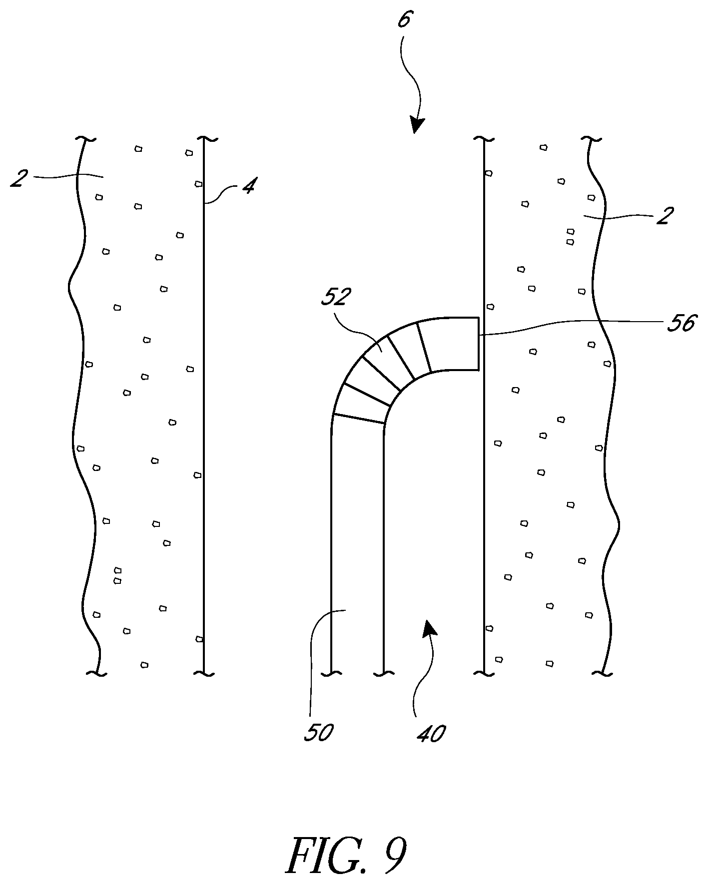
FIG. 9 is a schematic view of an embodiment of a suturing device in a body lumen.
FIG. 10 is a schematic view as in FIG. 9 showing a needle in an extended position.
FIG. 11 is a schematic view as in FIG. 10 showing a length of suture running through body tissue.
FIG. 12 is a schematic view as in FIG. 11 showing an embodiment of a suturing device in the body lumen.
FIG. 13 is a schematic view as in FIG. 12 showing a needle in an extended position.
FIG. 14 is a schematic view as in FIG. 13 showing two lengths of suture running through body tissue.
FIG. 15 is a schematic view as in FIG. 14 showing a length of suture extending across the body lumen.
FIG. 16 is a schematic view as in FIG. 15 the length of suture closing the body lumen.
DETAILED DESCRIPTION
Embodiments of suturing devices and methods which can be used to apply sutures to internal biological structures and internal body tissue are described herein. The suturing devices and methods can be used to place sutures from one side of a biological structure or tissue without the need to position a component of the device on a second side of a biological structure or tissue, and without the need to puncture the tissue with anything beyond a needle. This can increase the number of possible suture sites and minimize tissue damage, pain, and/or recovery time, among other advantages.
In the embodiments described herein, the disclosed devices can be used to place sutures in a variety of body locations. For example, in some embodiments, the disclosed suturing devices and methods are well-suited for passing suture through the wall of a tubular biological structure from a location within the lumen or around the ostium for the purpose of closing the tubular biological structure. In some embodiments, the suturing devices and methods can be used for tubal sterilization. In some embodiments, they can be used for procedures such as a vasectomy, treatment of bladders, or uterine prolapse. In some embodiments, the suturing devices and methods can be used to apply internal sutures to control and/or adjust positioning of breast implants, such as by applying skin grafts.
In some embodiments, the suturing devices can be used to close or reduce a variety of tissue openings, lumens, hollow organs, or natural or surgically created passageways in the body. In some embodiments, the suturing devices can be used to suture prosthetics, synthetic materials, or implantable devices in the body. For example, the devices can be used to suture a pledget within the body.
Suturing devices described herein can be delivered to a suturing site through a variety of methods. In some embodiments, a suturing device can be configured to follow a guide wire to a suturing site. In some embodiments, a delivery sheath can be inserted into a patient's body and a suturing device can be passed through the delivery sheath to the suturing site.
FIG. 1 illustrates one embodiment of a suturing device 10 that can be used to suture body tissue of a patient. The suturing device 10 can have a distal end 40 and a proximal end 42. It can include an elongate body 50 and, in some embodiments, can include a handle portion 20. In some embodiments, the handle portion 20 can include a housing 22 and one or more buttons, levers, or other actuating members such as a first button 24, a second button 26, and/or a third button 28. In various embodiments, different buttons can be used to actuate different components of the suturing device 10, as described in more detail below. Further details regarding handles and associated components are provided in U.S. Patent Publication No. 2008/0269786, published on Oct. 30, 2008, and U.S. Pat. No. 7,803,167, issued on Sep. 28, 2010, the contents of both of which are hereby incorporated by reference herein in their entirety.
FIG. 2 illustrates a schematic cross-sectional view of a distal end 40 of one embodiment of a suturing device. The elongate body 50 of the suturing device can have a distal-most face 56 that can be defined, at least in part, by a distal edge 58. In some embodiments, the distal face 56 can be left open or can be at least partially covered. In some embodiments, when the device is in use the distal face 56 can be positioned adjacent to or in contact with a tissue wall 4 of a body tissue 2 that is to be sutured.
In some embodiments, the suturing device can include a suture catch mechanism or needle 90. The needle 90 can be configured to move from a retracted position, in which the needle is partially or completely within the elongate body, to an extended position in which the needle 90 moves at least partially out from the elongate body 50. In some embodiments, the needle 90 can move into the extended position by passing through the distal-most face 56 of the elongate body 50. In some embodiments, the needle 90 can exit the elongate body 50 by passing through other faces. In some embodiments, the needle 90 can pass through a surface at the distal-most face 56.
The needle 90 can have a variety of configurations. In some embodiments, as illustrated in FIG. 2, the needle can have a tip 98 configured to engage a suture portion, as described below. In some embodiments, the tip 98 can be sharp to pierce tissue. In some embodiments, the needle 90 can have a curved section 96 and/or a lever section 94. In some embodiments, the needle 90 can be configured to rotate about a pivot point 92 that can define an axis of rotation for the needle.
The needle 90 can attach to a needle driver 70 that can drive the needle 90 from and to its retracted position. The needle 90 and needle driver 70 can attach to each other at the pivot point 92. The needle 90 and needle driver 70 can be fixed relative to each other. In some embodiments, the pivot point 92 can define an axis of rotation for both the needle 90 and the needle driver 70. In some embodiments, the needle driver 70 and needle 90 can fixedly connect to each other at a location that differs from an axis of rotation of the needle 90 and the needle driver 70.
In some embodiments, an actuator or push rod 80 can connect to the needle driver 70 at a connection point 82. The actuator or push rod 80 can be connected to a handle of the suturing device, and activating various buttons, levers, or other devices in the handle can cause the push rod 80 to move distally or proximally within the elongate body 50. In the illustrated embodiment, moving the push rod 80 proximally will provide a force on the needle driver 70 through the connection point 82. This force can cause the needle driver 70 to rotate about an axis of rotation, such as at the connection point 92, causing the needle 90 to rotate as well. When the needle driver 70 rotates, it can move the needle 90 from a retracted position, such as the position shown in FIG. 2, to an extended position, such as the position shown in FIG. 3. Preferably, the connection point 82 between the actuator 80 and the needle driver 70 can have at least one degree of freedom, such as by allowing relative rotation between the needle driver 70 and the actuator rod 80. In some embodiments, when the actuator rod 80 moves proximally or distally it can also move laterally, as illustrated.
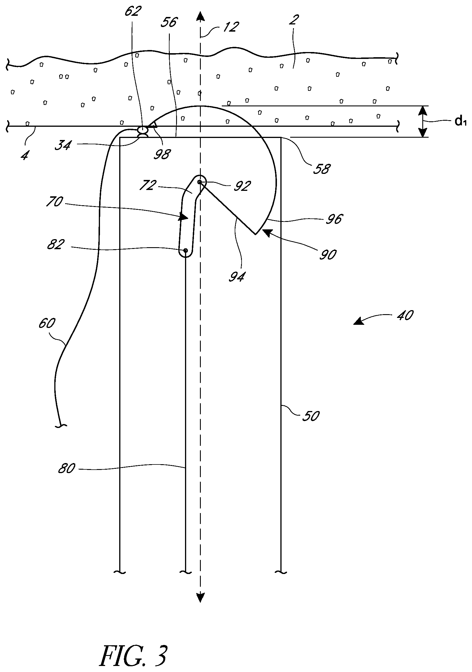
As shown in FIG. 3, as the needle 90 moves from the retracted position, the tip 98 of the needle 90 can leave the elongate body 50 by exiting through the distal face 56 of the elongate body. The needle 90 can then pass through the tissue wall 4 and into the body tissue 2. In some embodiments, the needle tip 98 can have a velocity when it first leaves the elongate body that differs from the velocity of the tip 98 when it reaches a portion of suture 60, described below. In some embodiments, the needle tip 98 can have a distal velocity component as the needle 90 first leaves the elongate body 50. As the needle 90 rotates, however, the tip 98 can turn and develop a proximal velocity component. The path of rotation can cause the needle 90 to turn and exit the tissue 2, passing through the tissue wall 4 a second time and at a location different from where it first passes through the tissue wall 4. In some embodiments, the needle 90 can exit the tissue 2 at the same location where it first passes through the tissue wall 4.
In some embodiments, the suturing device can include a suture holder or clasp 34 configured to be positioned in alignment with the path of the needle 90 when it exits the tissue 2. The suture holder or clasp 34 can be configured to releasably retain a capture portion 62 of suture 60 that is configured to be captured by the needle 90. In various embodiments, the capture portion can be a loop 62, sphere, ferrule, donut, or other configuration. In various embodiments, the suture holder or clasp 34 can include a circular opening with a diameter sized to securely receive and hold the capture portion. Further details regarding suture clasps are provided in U.S. Patent Publication No. 2008/0269786, the entirety of which is hereby incorporated by reference. In some embodiments, the suture holder or clasp 34 can be connected to the elongate body 50.
In various embodiments, the suture holder 34, capture portion 62, and suture 60 can be positioned at different locations. For example, as illustrated, in some embodiments the capture portion 62 can be on or adjacent the distal face 56. In some embodiments, the capture portion and suture holder 34 can be positioned proximal to the distal face 56 (e.g., within the elongate body 50). In some embodiments, the capture portion and suture holder 34 can be positioned distal to the distal face 56. In some embodiments, the capture portion and suture holder 34 can be positioned lateral to the distal face 56. In some embodiments, the capture portion and suture holder 34 can be configured to be positioned within or partially within the body tissue, such that a needle 90 can engage the capture portion 34 without exiting the tissue 2. The length of suture 60 is illustrated as passing outside of the elongate body 50, but in some embodiments the suture 60 can run within the elongate body to a position outside of a patient and/or outside of the suturing device.
Once the needle 90 has engaged the suture 60 at the capture portion 62, the needle 90 can be withdrawn back through the body tissue 2 and into the elongate body 50, bringing a portion of suture 80 with it. The needle 90 can be withdrawn by moving the actuator 80 distally, which can cause the needle driver 70 to rotate back towards its position in FIG. 2, drawing the needle 90 back towards its position in FIG. 2 as well. In some embodiments, a suturing device can be configured such that moving the actuator 80 in a distal direction drives the needle 90 from the retracted to extended position, and moving the actuator 80 in a proximal direction drives the needle 90 from an extended position to the retracted position.
In some embodiments, the needle 90 can be shaped in order pass a defined maximum distance or depth d.sub.1 from the elongate body. In some embodiments, where the distal-most face 56 of the elongate body is positioned flush against a tissue wall 4, the depth d.sub.1 can be approximately equal to the depth that the needle 90 passes through the tissue 2. In some embodiments, the elongate body 50 can be positioned a distance away from the tissue wall 4 in view of the maximum distance d.sub.1 to thereby adjust the depth that a needle 90 passes into the tissue 2 to a desired value. Various configurations to allow for setting this distance are described further below.
The needle driver 70 can be sized and positioned in different locations to affect the operation of a suturing apparatus. In some embodiments, for example, the needle driver 70 can have one or more bent or angled sections 72. This can affect the rotation of the needle driver 70 and the amount of space that it takes up within the elongate body 50. In some embodiments, the needle driver 70 can be positioned such that the pivot point 92 that defines an axis of rotation of the needle 90 is on a central longitudinal axis 12 of the elongate body 50. In some embodiments, the pivot point 92 can be positioned to one side or another of the central longitudinal axis 12.
In some embodiments, the needle driver 70 can be positioned such that the pivot point 92 that defines an axis of rotation of the needle 90 is proximal to the capture portion 62 of suture. In some embodiments, the needle driver 70 can be positioned such that the pivot point 92 that defines an axis of rotation of the needle 90 is in alignment with or distal to the capture portion 62 of suture.
As discussed above, the suturing device can be configured such that moving the actuator or push rod 80 in a proximal or distal direction will cause the needle driver 70 to move the needle 90 from a retracted position to an extended position. In some embodiments, the device is configured such that the push rod 80 can move either proximally or distally to move the needle 90 all the way into engagement with the suture portion 60. For example, in the illustrated embodiment, the connection 82 between the needle driver 70 and the actuator 80 can remain on the same side of the pivot point 92 through the range of motion of the needle 90 between the retracted and extended positions. Thus, a proximal force at the connection point 82 can be sufficient to move the needle 90 from the retracted to the extended position, and a distal force at the connection point can be sufficient to move the needle 90 from the extended to the retracted position. At least a portion of the actuator or push rod 80, however, can move laterally as the needle driver 70 rotates.
In various embodiments, the suture capture portion 62 can be positioned at different locations relative to the elongate body 50. As described above, for example, in some embodiments, the capture portion 34 can be positioned between a distal-most face 56 of the elongate body and tissue wall 4. In some embodiments, as illustrated in FIGS. 4 and 5, the suture loop 62 can be positioned at other locations.
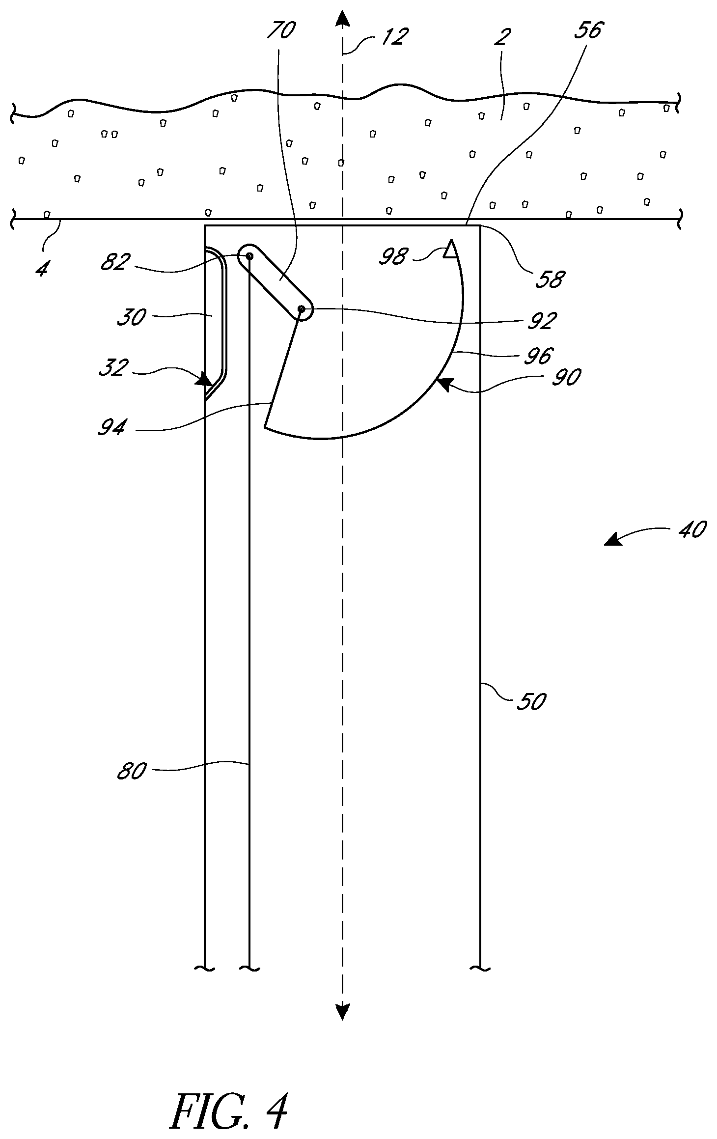
FIGS. 4 and 5 illustrate one embodiment of a suturing device that includes a suture arm 30. In FIG. 4, the suture arm 30 is in a retracted position in which at least a portion of the suture arm 30 is within the elongate body 50. In some embodiments, the entirety of the suture arm 30 can be within the elongate body 50 when the suture arm 30 is in the retracted position. The suture arm 30 can include a pivot 32 about which the suture arm 30 can move from the retracted to an extended position, illustrated in FIG. 5. In some embodiments, the pivot 32 can be at a proximal end of the suture arm 30 and the suture arm 30 can point distally, as illustrated, and in some embodiments, the pivot 32 can be at a distal end of the suture arm 30 and the suture arm 30 can point proximally. In some embodiments, the suture arm 30 can translate (such as by sliding, though other means can be used as well) from the retracted to extended position in addition to or instead of pivoting. In some embodiments, at least a portion of the suture arm 30 can be distal to the distal face 56 when in the extended position. In some embodiments, at least a portion of the suture arm 30 can be configured to pass through a tissue wall 4 when in the extended position.
In some embodiments, the suture arm 30 can include a suture clasp 34, which can be configured to releasably retain a capture portion 62 of a suture (not illustrated), such as a suture loop, donut, sphere, ferrule, etc. The needle 90 and needle driver 70 can be sized and configured such that the needle 90 in the extended position, as illustrated in FIG. 5, engages a capture portion of a suture releasably held by a suture clasp 34. The needle 90 can then draw the suture back through the body issue 2 as it returns to a retracted position, as illustrated in FIG. 4.
FIGS. 4 and 5 also illustrate an embodiment of a suturing device that has a needle driver 70 positioned such that the pivot point 92 and axis of rotation of the needle driver 70 and the needle 90 are offset from a central longitudinal axis 12 of the suturing device. FIGS. 4 and 5 also illustrate an embodiment of a suturing device in which the needle driver 70 is generally straight and does not have a bend 72.
In some embodiments, it can be desirable to modify the depth that the needle 90 passes into body tissue 92. In some embodiments, this can be done by using a device or component that can be configured to separate the elongate body from a tissue wall 4, which can lessen the distance that the needle 90 will pass into the body tissue 2. Preferably, the device or component can separate the elongate body from the tissue wall by a known, desired amount. In some embodiments, the elongate body can move relative to the needle driver 70 and needle 90, such that when the elongate body is positioned against the tissue wall 4, the pivot point 92 and axis of rotation of the needle can be farther from or closer to the tissue wall, thereby adjusting the depth that the needle can pass into body tissue.
In some embodiments, as illustrated in FIG. 6, an interior sheath 54 can be positioned within the elongate body 50 and can be independently movable within and relative to the elongate body 50. The sheath 54 can preferably be controlled from a proximal end of the suturing device, such as at the handle. In some embodiments, the suturing device can have a known maximum depth d.sub.1, as described and illustrated above. In some embodiments, the sheath 54 can be figured to protrude from a distal-most face 56 of the elongate body a known amount. When using the suturing device, the sheath 54 can be positioned adjacent to or against the tissue wall 4, which separates the distal-most face 56 of the elongate body 50 from the tissue wall 4 by that known amount. The depth of the needle d.sub.2 through the tissue is therefore the maximum depth d.sub.1 of the device less the known amount that the sheath 54 extends from the elongate body 50. Adjusting the position of the sheath 54 relative to the elongate body 50 therefore also adjusts the depth d.sub.2 that the needle 90 passes through tissue.
In some embodiments, the proximal end of the suturing device can include mechanisms to maintain the sheath 54 in a desired position. For example, in some embodiments the sheath 54 and a portion of the proximal end of the device, such as the handle, can have mating detents at discrete distance intervals. In some embodiments, the sheath 54 can be engaged relative to the elongate body 50 (e.g., with threading), such that rotating the sheath 54 relative to the elongate body advances or retracts the sheath 54. Different relative distances can be labeled at the proximal end of the device such that an operator can identify how far the sheath 54 extends from the elongate body 50.
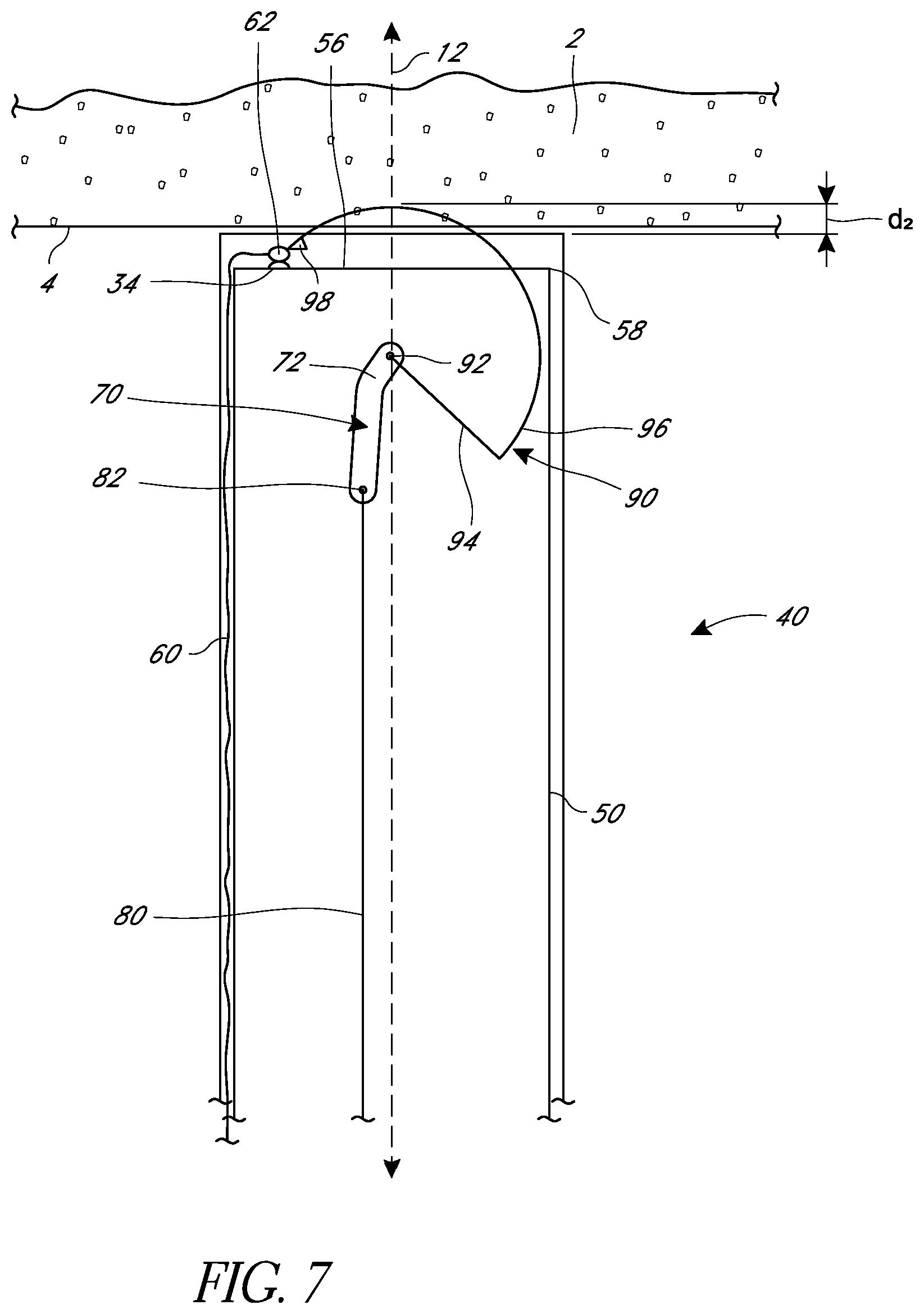
FIG. 6 illustrates the use of the sheath 54 with an embodiment of a suturing device that includes a suture arm 30, but the sheaths described herein are not limited to any particular embodiment and can be applied to any of the embodiments described herein. For example, FIG. 7 illustrates an embodiment of a suturing device that includes a sheath used with a suturing device that does not have a suture arm and that has the suture capture portion 62 positioned on or near the distal-most face 56 of the elongate body. In some embodiments, as further illustrated, a sheath can be an exterior sheath 55 that can be positioned at least partially around the elongate body 50. As above, the positioning of the sheath 55 can be adjusted from a proximal end of the suturing device. The sheath 55 can be used to separate the distal-most face 56 of the elongate body varying distances from a tissue wall 4 to thereby modify the depth d.sub.2 that the needle 90 passes through tissue 2.
In some embodiments, a suturing device can be delivered through an introducer sheath to a portion of tissue 2 needing to be sutured. In some embodiments, the introducer sheath can be configured to operate as a sheath used to separate the elongate body 50 from a tissue wall 4. In some embodiments, different sheaths can be used. In some embodiments, where an exterior sheath 55 is used to adjust the depth d.sub.2, the length of suture 60 can run between the elongate body 50 and the exterior sheath 55. In some embodiments, the suture 60 may run outside of both the elongate body and an exterior sheath 55. In some embodiments, the suture 60 may run inside or outside of an introducer sheath 55.
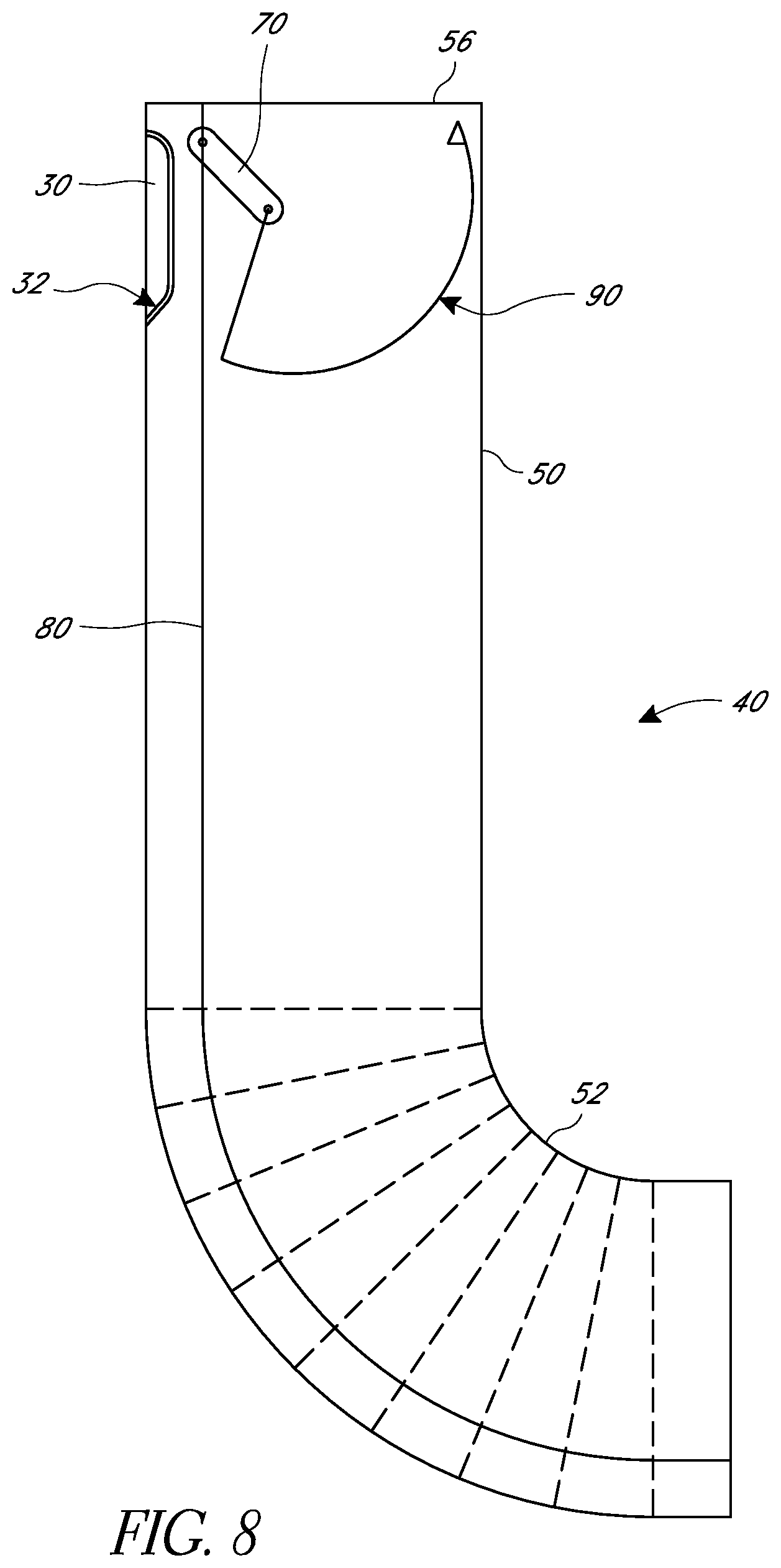
In various embodiments, a suturing device may be desirable for use at locations in a body that are not easily accessed or that have tight corners. In some embodiments, as illustrated in FIG. 8, the elongate body 50 of a suturing device can have one or more articulated sections 52 that can allow the elongate body to bend. This can help fit the elongate body 50 into a desired location and/or align a distal-most face 56 of the elongate body with tissue desired to be sutured. For example, in some embodiments the articulated sections 52 can allow the elongate body 50 to bend 30, 45, 90, 180, or 360.degree.. Further, in some embodiments the articulated sections 52 can be manually articulated from the handle or may be articulated by the body.
FIGS. 9-16 illustrate one embodiment of a method of using a suturing device to place suture in tissue surrounding a body lumen 6 in order to constrict or close the body lumen. As illustrated in FIG. 9, a distal end 40 of the elongate body 50 of the suturing device can be delivered within the body lumen 6, and the distal-most face 56 of the elongate body can be positioned adjacent, or directly on, the tissue wall 4 of the body tissue 2 desired to be sutured. In some embodiments, an articulated section 52 can be used to align the distal face 56 with the tissue wall 4. In some embodiments, the elongate body 50 can be directly aligned with a tissue wall 4 without articulating or as a result of a natural flexibility of the elongate body 50.
As illustrated in FIG. 10, a needle 90 can be extended as described above and can pass through a portion of the body tissue 2 in order to engage a suture portion (not illustrated). The needle 90 can be retracted to draw the suture portion through the tissue, also as described above, and into the elongate body 50. The elongate body can be withdrawn, as illustrated in FIG. 11, leaving a suture portion 60 through the body tissue 2.
FIG. 12 illustrates a suturing device positioned to pass sutures through a tissue wall 4 generally opposite the tissue wall that contains the suture portion 60. In some embodiments, a second suturing device can be used. In some embodiments, the suturing device used can be the same suturing device used to place the suture portion 60. In some embodiments, when the same suturing device is used, a device with multiple needles and/or suture portions can be used.
In FIG. 13, a needle 90 has moved from a retracted position to an extended position in which it passes through body tissue 2 and engages a suture portion (not illustrated). The needle 90 can then be withdrawn, bringing the suture portion with it through the body tissue and into the elongate body 50.
In FIG. 14, the suturing device has been withdrawn from the lumen 6, leaving a first suture portion 60 and a second suture portion 60'. In some embodiments, the first suture portion 60 and second suture portion 60' can be lengths of the same suture. In some embodiments, they can be different suture portions and their ends can be connected together to form a single loop of suture. Further details regarding a device for joining sutures are provided in U.S. Patent Application Publication No. 2011/0190793, published on Aug. 4, 2011, which is hereby incorporated by reference herein in its entirety.
In FIG. 15, suture ends have been joined to form a single loop of suture 60 that passes through body tissue on opposite sides of the lumen 6, and the loose suture ends have been pulled to draw the loop into the body lumen. Pulling the loose suture ends further can draw opposing tissue walls 4 together, as illustrated in FIG. 16. This can constrict the body lumen 6. In some embodiments, the suture ends can be pulled even further to draw the opposite sides of the body lumen 6 into contact with each other to thereby close the lumen. In some embodiments, the illustrated suture portion 60 can represent one of a plurality of suture portions used to constrict and/or close off a body lumen. For example, in some embodiments, in addition to the illustrated suture portion 60, suture portions passing through opposing tissue walls 4 in planes different from the illustrated plane can be inserted according to methods described above and can be pulled to help close the body lumen in different planes.
From the foregoing description, it will be appreciated that inventive suturing devices and methods are disclosed. While several components, techniques and aspects have been described with a certain degree of particularity, it is manifest that many changes can be made in the specific designs, constructions and methodology herein above described without departing from the spirit and scope of this disclosure.
Certain features that are described in this disclosure in the context of separate implementations can also be implemented in combination in a single implementation. Conversely, various features that are described in the context of a single implementation can also be implemented in multiple implementations separately or in any suitable subcombination. Moreover, although features may be described above as acting in certain combinations, one or more features from a claimed combination can, in some cases, be excised from the combination, and the combination may be claimed as any subcombination or variation of any subcombination.
Moreover, while methods may be depicted in the drawings or described in the specification in a particular order, such methods need not be performed in the particular order shown or in sequential order, and that all methods need not be performed, to achieve desirable results. Other methods that are not depicted or described can be incorporated in the example methods and processes. For example, one or more additional methods can be performed before, after, simultaneously, or between any of the described methods. Further, the methods may be rearranged or reordered in other implementations. Also, the separation of various system components in the implementations described above should not be understood as requiring such separation in all implementations, and it should be understood that the described components and systems can generally be integrated together in a single product or packaged into multiple products. Additionally, other implementations are within the scope of this disclosure.
Conditional language, such as "can," "could," "might," or "may," unless specifically stated otherwise, or otherwise understood within the context as used, is generally intended to convey that certain embodiments include or do not include, certain features, elements, and/or steps. Thus, such conditional language is not generally intended to imply that features, elements, and/or steps are in any way required for one or more embodiments.
Conjunctive language such as the phrase "at least one of X, Y, and Z," unless specifically stated otherwise, is otherwise understood with the context as used in general to convey that an item, term, etc. may be either X, Y, or Z. Thus, such conjunctive language is not generally intended to imply that certain embodiments require the presence of at least one of X, at least one of Y, and at least one of Z.
Language of degree used herein, such as the terms "approximately," "about," "generally," and "substantially" as used herein represent a value, amount, or characteristic close to the stated value, amount, or characteristic that still performs a desired function or achieves a desired result. For example, the terms "approximately", "about", "generally," and "substantially" may refer to an amount that is within less than or equal to 10% of, within less than or equal to 5% of, within less than or equal to 1% of, within less than or equal to 0.1% of, and within less than or equal to 0.01% of the stated amount.
Some embodiments have been described in connection with the accompanying drawings. The figures are drawn to scale, but such scale should not be limiting, since dimensions and proportions other than what are shown are contemplated and are within the scope of the disclosed inventions. Distances, angles, etc. are merely illustrative and do not necessarily bear an exact relationship to actual dimensions and layout of the devices illustrated. Components can be added, removed, and/or rearranged. Further, the disclosure herein of any particular feature, aspect, method, property, characteristic, quality, attribute, element, or the like in connection with various embodiments can be used in all other embodiments set forth herein. Additionally, it will be recognized that any methods described herein may be practiced using any device suitable for performing the recited steps.
While a number of embodiments and variations thereof have been described in detail, other modifications and methods of using the same will be apparent to those of skill in the art. Accordingly, it should be understood that various applications, modifications, materials, and substitutions can be made of equivalents without departing from the unique and inventive disclosure herein or the scope of the claims.
* * * * *
D00000
D00001
D00002
D00003
D00004
D00005
D00006
D00007
D00008
D00009
D00010
D00011
D00012

D00013
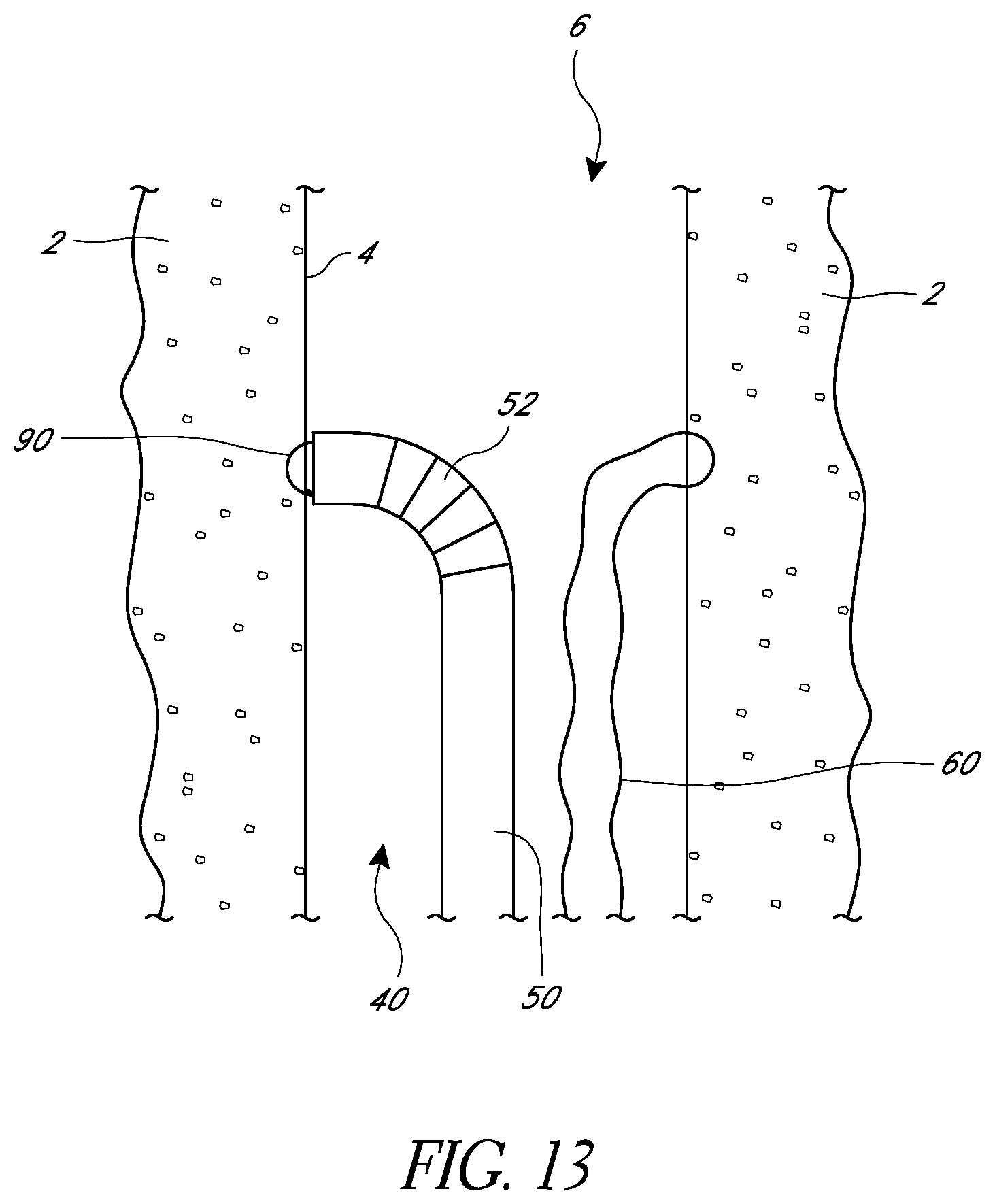
D00014
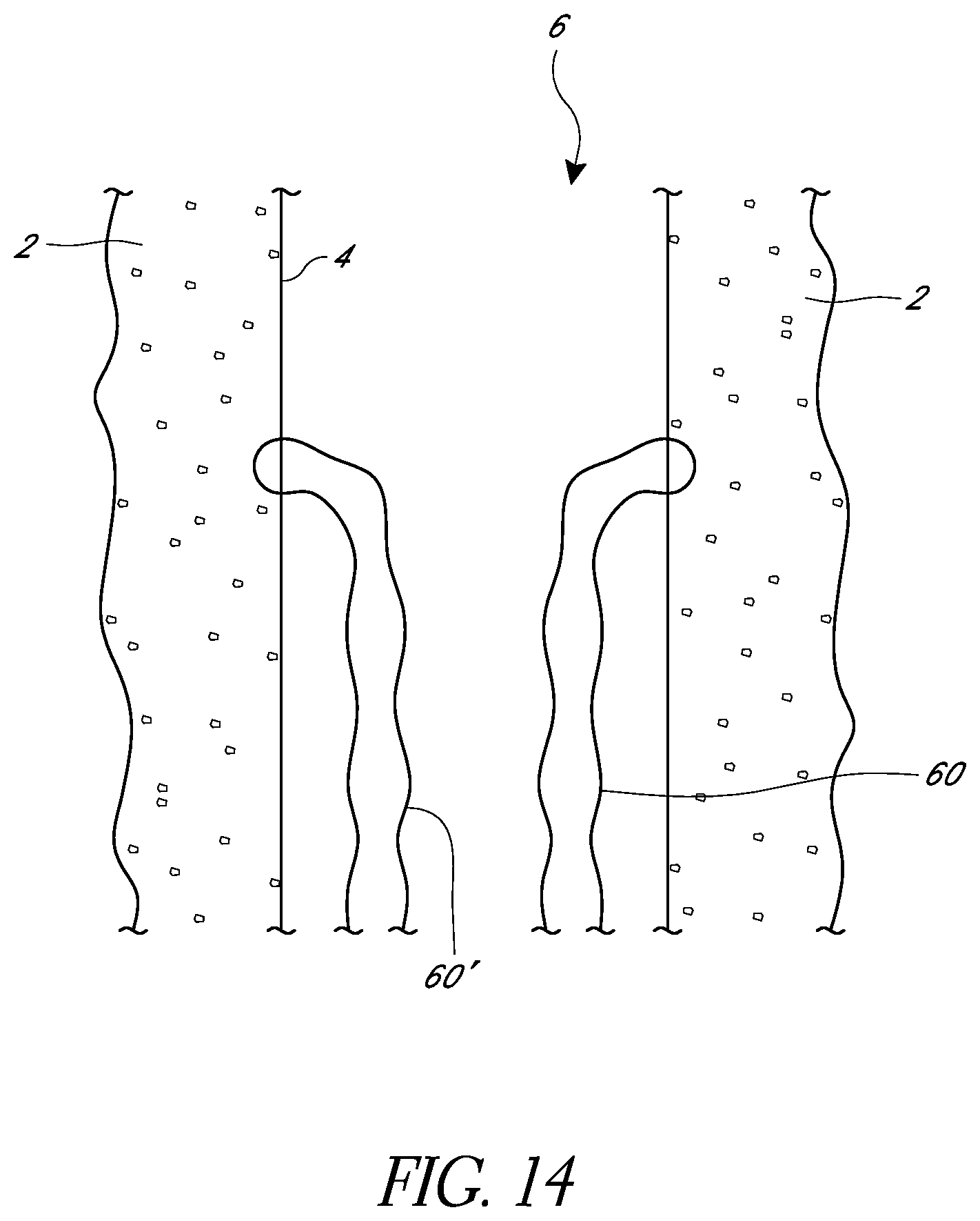
D00015

D00016
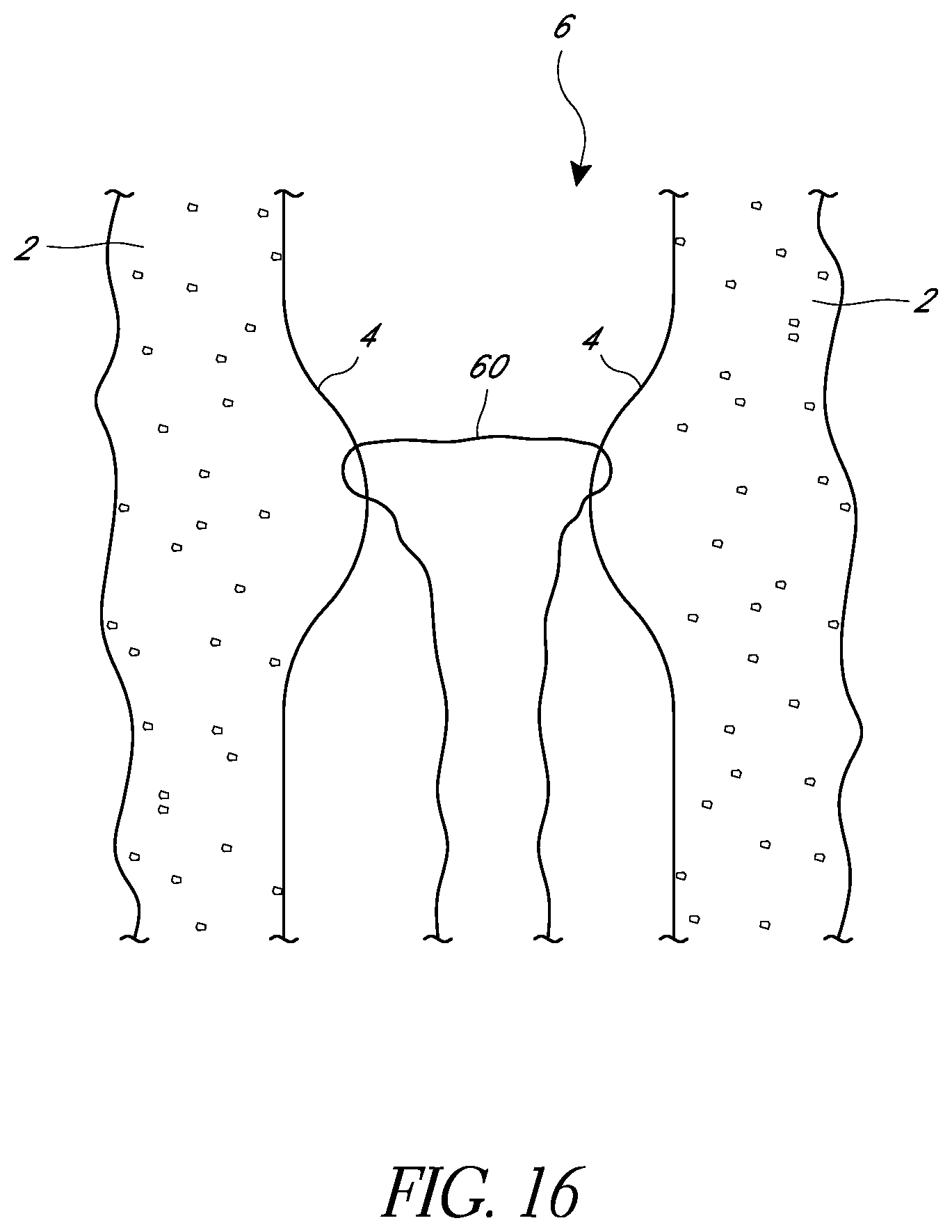
XML
uspto.report is an independent third-party trademark research tool that is not affiliated, endorsed, or sponsored by the United States Patent and Trademark Office (USPTO) or any other governmental organization. The information provided by uspto.report is based on publicly available data at the time of writing and is intended for informational purposes only.
While we strive to provide accurate and up-to-date information, we do not guarantee the accuracy, completeness, reliability, or suitability of the information displayed on this site. The use of this site is at your own risk. Any reliance you place on such information is therefore strictly at your own risk.
All official trademark data, including owner information, should be verified by visiting the official USPTO website at www.uspto.gov. This site is not intended to replace professional legal advice and should not be used as a substitute for consulting with a legal professional who is knowledgeable about trademark law.