Vehicle computing system to provide feedback
Vartanian , et al. De
U.S. patent number 10,496,170 [Application Number 15/498,122] was granted by the patent office on 2019-12-03 for vehicle computing system to provide feedback. This patent grant is currently assigned to HJ Laboratories, LLC. The grantee listed for this patent is HJ Laboratories, LLC. Invention is credited to Jaron Jurikson-Rhodes, Harry Vartanian.


| United States Patent | 10,496,170 |
| Vartanian , et al. | December 3, 2019 |
Vehicle computing system to provide feedback
Abstract
A vehicle computing system may provide feedback in a vehicle, using a vehicle processor of the vehicle. A touch display may display windows with different vibrations to provide the feedback. A vibration may vary in relation to data.
| Inventors: | Vartanian; Harry (Bryn Mawr, PA), Jurikson-Rhodes; Jaron (Philadelphia, PA) | ||||||||||
|---|---|---|---|---|---|---|---|---|---|---|---|
| Applicant: |
|
||||||||||
| Assignee: | HJ Laboratories, LLC (Bryn
Mawr, PA) |
||||||||||
| Family ID: | 44369327 | ||||||||||
| Appl. No.: | 15/498,122 | ||||||||||
| Filed: | April 26, 2017 |
Prior Publication Data
| Document Identifier | Publication Date | |
|---|---|---|
| US 20170228023 A1 | Aug 10, 2017 | |
Related U.S. Patent Documents
| Application Number | Filing Date | Patent Number | Issue Date | ||
|---|---|---|---|---|---|
| 12706205 | Feb 16, 2010 | ||||
| Current U.S. Class: | 1/1 |
| Current CPC Class: | G06F 3/043 (20130101); G06F 3/0488 (20130101); G06F 3/0416 (20130101); G06F 3/04886 (20130101); G06F 3/016 (20130101); G06F 3/04845 (20130101); B60K 2370/113 (20190501); B60K 2370/1438 (20190501); B60K 2370/11 (20190501); G06F 2203/04108 (20130101); G06F 2203/04809 (20130101); G06F 2203/014 (20130101); G06F 2203/04102 (20130101) |
| Current International Class: | G06F 3/01 (20060101); G06F 3/043 (20060101); G06F 3/0484 (20130101); G06F 3/041 (20060101); G06F 3/0488 (20130101) |
References Cited [Referenced By]
U.S. Patent Documents
| 4871992 | October 1989 | Petersen |
| 5327457 | July 1994 | Leopold |
| 5402490 | March 1995 | Mihm, Jr. |
| 5412189 | May 1995 | Cragun |
| 5463657 | October 1995 | Rice |
| 5490087 | February 1996 | Redden et al. |
| 5504938 | April 1996 | Redden |
| 5602901 | February 1997 | Redden et al. |
| 5673256 | September 1997 | Maine |
| 5712870 | January 1998 | Petrick |
| 5717434 | February 1998 | Toda |
| 5724659 | March 1998 | Daniel et al. |
| 5752162 | May 1998 | Sawyer et al. |
| 5825308 | October 1998 | Rosenberg |
| 5867144 | February 1999 | Wyard |
| 5867789 | February 1999 | Olds et al. |
| 5888161 | March 1999 | McCarrick et al. |
| 5892902 | April 1999 | Clark |
| 6004049 | December 1999 | Knox |
| 6037882 | March 2000 | Levy |
| 6075967 | June 2000 | Naimark et al. |
| 6104922 | August 2000 | Baumann |
| 6117296 | September 2000 | Thomson |
| 6131032 | October 2000 | Patel |
| 6140913 | October 2000 | Okada et al. |
| 6185536 | February 2001 | Haber et al. |
| 6204896 | March 2001 | Matsuhira et al. |
| 6243078 | June 2001 | Rosenberg |
| 6255938 | July 2001 | Bornschein |
| 6266690 | July 2001 | Shankarappa et al. |
| 6313825 | November 2001 | Gilbert |
| 6359978 | March 2002 | Brady |
| 6434702 | August 2002 | Maddalozzo, Jr. et al. |
| 6441828 | August 2002 | Oba et al. |
| 6456245 | September 2002 | Crawford |
| 6462840 | October 2002 | Kravtsov |
| 6487657 | November 2002 | Brockmann |
| 6492979 | December 2002 | Kent et al. |
| 6535201 | March 2003 | Cooper et al. |
| 6559620 | May 2003 | Zhou et al. |
| 6563487 | May 2003 | Martin et al. |
| 6571102 | May 2003 | Hogberg et al. |
| 6597347 | July 2003 | Yasutake |
| 6628511 | September 2003 | Engstrom |
| 6646540 | November 2003 | Lussey |
| 6680731 | January 2004 | Gerpheide et al. |
| 6700553 | March 2004 | Becker et al. |
| 6703550 | March 2004 | Chu |
| 6744178 | June 2004 | Muramatsu et al. |
| 6782102 | August 2004 | Blanchard et al. |
| 6787238 | September 2004 | Zhang et al. |
| 6823787 | November 2004 | Saueressig |
| 6842428 | January 2005 | Chen et al. |
| 6842607 | January 2005 | Godfrey et al. |
| 6852416 | February 2005 | Zhang et al. |
| 6859569 | February 2005 | Ishibashi et al. |
| 6859572 | February 2005 | Ishibashi |
| 6881063 | April 2005 | Yang |
| 6882086 | April 2005 | Kornbluh et al. |
| 6888161 | May 2005 | Shih |
| 6925495 | August 2005 | Hegde et al. |
| 6984208 | January 2006 | Zheng |
| 6988247 | January 2006 | Janevski |
| 7027311 | April 2006 | Vanderelli et al. |
| 7042711 | May 2006 | Tanaka et al. |
| 7042997 | May 2006 | Jones |
| 7050835 | May 2006 | Hack et al. |
| 7054145 | May 2006 | Tanaka et al. |
| 7077015 | July 2006 | Hayward et al. |
| 7102621 | September 2006 | Roberts |
| 7109967 | September 2006 | Hioki et al. |
| 7113177 | September 2006 | Franzen |
| 7138985 | November 2006 | Nakajima |
| 7151527 | December 2006 | Culver |
| 7184032 | February 2007 | Stohrer et al. |
| 7186356 | March 2007 | Lussey et al. |
| 7190416 | March 2007 | Paukshto et al. |
| 7193350 | March 2007 | Blackburn et al. |
| 7253807 | August 2007 | Nakajima |
| 7269153 | September 2007 | Schultz et al. |
| 7274652 | September 2007 | Webster et al. |
| 7301435 | November 2007 | Lussey et al. |
| 7317872 | January 2008 | Posa et al. |
| 7339572 | March 2008 | Schena |
| 7352356 | April 2008 | Roberts et al. |
| 7368307 | May 2008 | Cok |
| 7377133 | May 2008 | Sandbach et al. |
| 7382357 | June 2008 | Panotopoulos et al. |
| 7400640 | July 2008 | Fischer et al. |
| 7406057 | July 2008 | Isomaki et al. |
| 7408872 | August 2008 | Palin et al. |
| 7436318 | October 2008 | Affolter et al. |
| 7444157 | October 2008 | Hovers et al. |
| 7455304 | November 2008 | Porter |
| 7461353 | December 2008 | Rohrabaugh et al. |
| 7495348 | February 2009 | Mund et al. |
| 7500952 | March 2009 | Chiang et al. |
| 7511702 | March 2009 | Hotelling |
| 7522153 | April 2009 | Ohtsuka |
| 7548232 | June 2009 | Shahoian et al. |
| 7554045 | June 2009 | Sandbach et al. |
| 7554051 | June 2009 | Crispin |
| 7561141 | July 2009 | Shahoian et al. |
| 7567243 | July 2009 | Hayward |
| 7592999 | September 2009 | Rosenberg et al. |
| 7593067 | September 2009 | Taguchi |
| 7656394 | February 2010 | Westerman et al. |
| 7731670 | June 2010 | Aguirre-Ollinger et al. |
| 7756297 | July 2010 | Pryor |
| 7787646 | August 2010 | Pelrine et al. |
| 7828733 | November 2010 | Zhang et al. |
| 7841944 | November 2010 | Wells |
| 7843449 | November 2010 | Krah |
| 7893928 | February 2011 | Im |
| 7953462 | May 2011 | Harry |
| 7982588 | July 2011 | Makinen et al. |
| 8068101 | November 2011 | Goertz |
| 8095879 | January 2012 | Goertz |
| 8125463 | February 2012 | Hotelling et al. |
| 8136402 | March 2012 | Cato |
| 8169416 | May 2012 | Han |
| 8232973 | July 2012 | Kocienda et al. |
| 8255323 | August 2012 | Casey et al. |
| 8406816 | March 2013 | Marui et al. |
| 8433138 | April 2013 | Wang et al. |
| 8547339 | October 2013 | Ciesla |
| 8558803 | October 2013 | Park et al. |
| 8593409 | November 2013 | Heubel |
| 8619051 | December 2013 | Lacroix et al. |
| 8686952 | April 2014 | Burrough et al. |
| 8773356 | July 2014 | Martin et al. |
| 8825113 | September 2014 | Kim et al. |
| 9244173 | January 2016 | Vartanian et al. |
| 9250734 | February 2016 | Hotelling et al. |
| 9332113 | May 2016 | Vartanian |
| 2001/0020202 | September 2001 | Obradovich |
| 2002/0030699 | March 2002 | Van Ee |
| 2002/0050983 | May 2002 | Liu et al. |
| 2002/0158836 | October 2002 | Ishmael |
| 2003/0038776 | February 2003 | Rosenberg et al. |
| 2003/0048260 | March 2003 | Matusis |
| 2003/0058265 | March 2003 | Robinson et al. |
| 2004/0056877 | March 2004 | Nakajima |
| 2004/0100448 | May 2004 | Moshrefzadeh |
| 2004/0199232 | October 2004 | Wallace et al. |
| 2004/0212599 | October 2004 | Cok |
| 2005/0012723 | January 2005 | Pallakoff |
| 2005/0088417 | April 2005 | Mulligan |
| 2005/0157893 | July 2005 | Pelrine et al. |
| 2006/0007078 | January 2006 | Lee et al. |
| 2006/0022955 | February 2006 | Kennedy |
| 2006/0092344 | May 2006 | Ura et al. |
| 2006/0096392 | May 2006 | Inkster et al. |
| 2006/0103634 | May 2006 | Kim et al. |
| 2006/0186802 | August 2006 | Cok et al. |
| 2006/0197752 | September 2006 | Hurst et al. |
| 2006/0197753 | September 2006 | Hotelling |
| 2006/0209083 | September 2006 | Rosenberg |
| 2006/0221016 | October 2006 | Nakamura |
| 2007/0020589 | January 2007 | Smith et al. |
| 2007/0078345 | April 2007 | Mo et al. |
| 2007/0085828 | April 2007 | Schroeder et al. |
| 2007/0085838 | April 2007 | Ricks et al. |
| 2007/0091070 | April 2007 | Larsen et al. |
| 2007/0106949 | May 2007 | Narita et al. |
| 2007/0109276 | May 2007 | Kim et al. |
| 2007/0139391 | June 2007 | Bischoff |
| 2007/0152962 | July 2007 | Kim et al. |
| 2007/0152974 | July 2007 | Kim et al. |
| 2007/0182708 | August 2007 | Poupyrev et al. |
| 2007/0193267 | August 2007 | He |
| 2007/0200496 | August 2007 | Cok et al. |
| 2007/0220427 | September 2007 | Briancon et al. |
| 2007/0247422 | October 2007 | Vertegaal et al. |
| 2007/0247429 | October 2007 | Westerman |
| 2007/0257891 | November 2007 | Esenther et al. |
| 2008/0005703 | January 2008 | Radivojevic et al. |
| 2008/0042981 | February 2008 | Katz |
| 2008/0062088 | March 2008 | Chang et al. |
| 2008/0062148 | March 2008 | Hotelling et al. |
| 2008/0100907 | May 2008 | Lipovetskaya et al. |
| 2008/0122589 | May 2008 | Ivanov |
| 2008/0129705 | June 2008 | Kim et al. |
| 2008/0136786 | June 2008 | Lanfermann |
| 2008/0150911 | June 2008 | Harrison |
| 2008/0180399 | July 2008 | Cheng |
| 2008/0180406 | July 2008 | Han et al. |
| 2008/0211353 | September 2008 | Seeley et al. |
| 2008/0216001 | September 2008 | Ording et al. |
| 2008/0224948 | September 2008 | Alberth |
| 2008/0231610 | September 2008 | Hotelling et al. |
| 2008/0246726 | October 2008 | Gettemy |
| 2008/0259236 | October 2008 | Kwon et al. |
| 2008/0291521 | November 2008 | Kim et al. |
| 2008/0291525 | November 2008 | Kim et al. |
| 2008/0303795 | December 2008 | Lowles et al. |
| 2009/0002140 | January 2009 | Higa |
| 2009/0002205 | January 2009 | Klinghult et al. |
| 2009/0002328 | January 2009 | Ullrich et al. |
| 2009/0015560 | January 2009 | Robinson et al. |
| 2009/0043195 | February 2009 | Poland |
| 2009/0043205 | February 2009 | Pelissier et al. |
| 2009/0051662 | February 2009 | Klein et al. |
| 2009/0061948 | March 2009 | Lee et al. |
| 2009/0070711 | March 2009 | Kwak |
| 2009/0102805 | April 2009 | Meijer et al. |
| 2009/0153368 | June 2009 | Hur et al. |
| 2009/0160813 | June 2009 | Takashima et al. |
| 2009/0167704 | July 2009 | Terlizzi et al. |
| 2009/0174671 | July 2009 | Tachi et al. |
| 2009/0174687 | July 2009 | Ciesla et al. |
| 2009/0181724 | July 2009 | Pettersson |
| 2009/0182501 | July 2009 | Fyke et al. |
| 2009/0184936 | July 2009 | Algreatly |
| 2009/0189748 | July 2009 | Bergere |
| 2009/0189873 | July 2009 | Peterson et al. |
| 2009/0189878 | July 2009 | Goertz et al. |
| 2009/0195512 | August 2009 | Pettersson |
| 2009/0198132 | August 2009 | Pelissier et al. |
| 2009/0199392 | August 2009 | Singh et al. |
| 2009/0213066 | August 2009 | Hardacker et al. |
| 2009/0231271 | September 2009 | Heubel et al. |
| 2009/0237364 | September 2009 | Bloomcamp et al. |
| 2009/0256807 | October 2009 | Nurmi |
| 2009/0256857 | October 2009 | Davidson et al. |
| 2009/0262078 | October 2009 | Pizzi |
| 2009/0284480 | November 2009 | Seacat |
| 2009/0286211 | November 2009 | Eisenhardt et al. |
| 2009/0292990 | November 2009 | Park |
| 2009/0295760 | December 2009 | Linge et al. |
| 2009/0303022 | December 2009 | Griffin et al. |
| 2009/0309851 | December 2009 | Bernstein |
| 2009/0315830 | December 2009 | Westerman |
| 2009/0315851 | December 2009 | Hotelling et al. |
| 2009/0322687 | December 2009 | Duncan et al. |
| 2009/0322695 | December 2009 | Cho |
| 2010/0001973 | January 2010 | Hotelling et al. |
| 2010/0007511 | January 2010 | Ina et al. |
| 2010/0007613 | January 2010 | Costa |
| 2010/0013777 | January 2010 | Baudisch et al. |
| 2010/0026656 | February 2010 | Hotelling et al. |
| 2010/0085169 | April 2010 | Poupyrev et al. |
| 2010/0115448 | May 2010 | Lysytskyy et al. |
| 2010/0128002 | May 2010 | Stacy et al. |
| 2010/0151426 | June 2010 | Tachi et al. |
| 2010/0156803 | June 2010 | Wu |
| 2010/0156818 | June 2010 | Burrough et al. |
| 2010/0160786 | June 2010 | Nordgren et al. |
| 2010/0162109 | June 2010 | Chatterjee et al. |
| 2010/0171715 | July 2010 | Peterson et al. |
| 2010/0177050 | July 2010 | Heubel et al. |
| 2010/0177055 | July 2010 | Ookawara et al. |
| 2010/0182245 | July 2010 | Edwards et al. |
| 2010/0207775 | August 2010 | Lenneman et al. |
| 2010/0207902 | August 2010 | Juan et al. |
| 2010/0225456 | September 2010 | Eldering |
| 2010/0225734 | September 2010 | Weller et al. |
| 2010/0231540 | September 2010 | Cruz-Hernandez et al. |
| 2010/0231541 | September 2010 | Cruz-Hernandez et al. |
| 2010/0234077 | September 2010 | Yoo et al. |
| 2010/0238114 | September 2010 | Vartanian et al. |
| 2010/0238116 | September 2010 | Shin |
| 2010/0238117 | September 2010 | Fitzgibbon et al. |
| 2010/0257491 | October 2010 | Geurts et al. |
| 2010/0259633 | October 2010 | Kii |
| 2010/0283731 | November 2010 | Grant et al. |
| 2010/0295820 | November 2010 | Kikin-Gil |
| 2010/0298713 | November 2010 | Robinson |
| 2011/0043485 | February 2011 | Goertz |
| 2011/0066320 | March 2011 | Bechtler |
| 2011/0107958 | May 2011 | Pance et al. |
| 2011/0109588 | May 2011 | Makinen et al. |
| 2011/0175813 | July 2011 | Sarwar et al. |
| 2011/0199342 | August 2011 | Vartanian et al. |
| 2012/0231927 | September 2012 | Beechie |
| 2012/0242592 | September 2012 | Rothkopf |
| 2014/0195926 | July 2014 | Hussain |
| 2015/0251633 | September 2015 | Flick |
| 2016/0214504 | July 2016 | Park |
| 2017/0225619 | August 2017 | Torii |
| 2018/0009319 | January 2018 | Sakuishi |
| 676781 | Jan 1999 | EP | |||
| 2382291 | May 2003 | GB | |||
| 2001117721 | Apr 2001 | JP | |||
| 2003029898 | Jan 2003 | JP | |||
| 3739927 | Jan 2006 | JP | |||
| 3913496 | May 2007 | JP | |||
| 20040076415 | Sep 2004 | KR | |||
| 20080023901 | Mar 2008 | KR | |||
| 594183 | Jun 2004 | TW | |||
| 9917929 | Apr 1999 | WO | |||
| 03003185 | Jan 2003 | WO | |||
| 07012899 | Feb 2007 | WO | |||
| 07069835 | Jun 2007 | WO | |||
| 2007114699 | Oct 2007 | WO | |||
| 2008037275 | Apr 2008 | WO | |||
| 2010054014 | May 2010 | WO | |||
| 2010085575 | Jul 2010 | WO | |||
| 10086866 | Aug 2010 | WO | |||
Other References
|
Iwamoto et al., "A Tactile Display using Ultrasound Linear Phased Array", International Conference on Artificial Reality and Telexistence, 2004, Seoul, Korea. cited by applicant . Asamura et al., "A Tactile Feeling Display Based on Selective Stimulation to Skin Receptors", Proceeding of the IEEE Virtual Reality Annual International Symposium, Mar. 1998, pp. 36-42, Atlanta, GA. cited by applicant . Hoshi et al., "Adding Tactile Reaction to Hologram", The 18th IEEE International Symposium on Robot and Human Interactive Communication, Sep. 27-Oct. 2, 2009, pp. 7-11, Toyama, Japan. cited by applicant . Iwamoto et al., "Finger Ring Device for Tactile Sensing and Human Machine Interface", SICE Annual Conference 2007, Kagawa University, Sep. 17-20, 2007, pp. 2132-2136, Japan. cited by applicant . Kim et al., "Small and Lightweight Tactile Display(SaLT) and Its Application", Third Joint Eurohaptics Conference and Symposium on Haptic Interfaces for Virtual Environment and Teleoperator Systems, pp. 69-74, Mar. 18-20, 2009, Salt Lake City, UT. cited by applicant . Chouvardas et al., "Tactile display applications: a state of the art survey", 2005. cited by applicant . Chouvardas et al., "Tactile Displays: a short overview and recent developments", 2007. cited by applicant . Khoudja et al., "Tactile interfaces: a state-of-the-art survey", CEA List SRSI, pp. 1-9, 2004, France. cited by applicant . Iwamoto et al., "Two Dimensional Stress Reproduction Using Ultrasound Tactile Display", SICE-ICASE International Joint Conference, Oct. 18-21, 2006, pp. 4818-4821, Busan, Korea. cited by applicant . Iwamoto et al., "Two-dimensional Scanning Tactile Display using Ultrasound Radiation Pressure", 14th Symposium on Haptic Interfaces for Virtual Environment and Teleoperator Systems, Mar. 2006, pp. 57-61. cited by applicant . Shinoda et al., "Touchable Holography" http://www.youtube.com/watch?v=Y-P1zZAcPuw, Siggraph2009, Posted Jul. 16, 2009, University of Tokyo. cited by applicant . Iwamoto, T et al., Airborne Ultrasound Tactile Display, SIGGRAPH 2008 New Tech Demos, Aug. 2008. cited by applicant . "Apple Introduces the Incredible Shape Shifting Device Interface," Patently Apple, Jun. 24, 2010. cited by applicant . "Artificial muscles get a makeover," accessed at http://www.msnbc.msn.com/id/11858650/, Mar. 16, 2006. cited by applicant . Zyga, L., "Researchers Design Band-Aid-Size Tactile Display," PHYSORG.com, Jun. 6, 2006. cited by applicant . "Electric Flex," (2001) Date Unknown, accessed at http://www.Spectrum.ieee.org/print/1579. cited by applicant . "Fundamental research on polymer material as artificial muscle," Apr. 1, 2008 (Abstract). cited by applicant . "Materials and Technologies for Artificial Muscle: A Review for the Mechatronic Muscle Project," Date Unknown. cited by applicant . "New Class of Composite Organic Material Could Put the Muscle in Artificial Body Parts," Sep. 19, 2002. cited by applicant . "New Polymers and Nanotubes Add Muscle to Prosthetic Limbs," Aug. 1999. cited by applicant . "PulseTouch.TM. technology," Date Unknown. cited by applicant . "Refreshable Braille Display," Date Unknown. cited by applicant . "Small jolts move artificial muscle," Oct. 2/9, 2002. cited by applicant . "Sony's Flexible OLED," accessed at http://www.youtube.com/watch?v=NcAm3KihFho, Uploaded on Jun. 27, 2007. cited by applicant . "Team post Braille ebook concept," bit-tech.net, Apr. 21, 2009. cited by applicant . "Two Dimensional Radiation Pressure Tactile Display," Aug. 8-10, 2005. cited by applicant . "Unusual material that contracts when heated is giving up its secrets to physicists," Nov. 18, 2004. cited by applicant . "W&M Professor Heads Facility Studying Piezoelectric Material," Jul. 6, 2001. cited by applicant . 3DTV Experience--Philips WOWvx 3D Display; Date Unknown. cited by applicant . Amemiya et al., "Portable Haptic Feedback Display for Virtual Reality," 1999, Abstract Only. cited by applicant . "Artificial Muscle Material with Fast Electroactuation under Neutral pH Conditions," Abstract Only, May 21, 2004. cited by applicant . Bau, et al., "BubbleWrap: A Textile-Based Electromagnetic Haptic Display", CHI 2009, Apr. 4-9, 2009, Boston, Massachusetts, USA. cited by applicant . Davies, C., "NHK develop precise haptic-feedback touchscreen," Slashgear, May 16, 2008. cited by applicant . Harrison et al., "Texture Displays: A Passive Approach to Tactile Presentation," Apr. 9, 2009. cited by applicant . Howe, R., "The Haptic Community Web Site--Haptic Research: Tactile Display", Apr. 3, 2002. cited by applicant . Vijayan, J., "User interfaces: The next generation," Aug. 9, 2004. cited by applicant . "NC State Scientists Engineer `Pumped-Up,` Materials," accessed Sep. 6, 2007. cited by applicant . Ooshita et al., "Tokyo University Realizes Light-weight, Flexible Braille Display Sheet Using Organic Transistors," Nov. 25, 2005. cited by applicant . "TouchEngine: A Tactile Display for Handheld Devices" Proceedings of CHI 2002, Extended Abstracts. 2002: ACM: pp. 644-645. cited by applicant . Poupyrev et al., "Haptic feedback for pen computing: directions and strategies," 2004, Abstract Only. cited by applicant . Sharifi et al., "Design and implementation of a graphic-haptic display system", Nov. 24, 2006. cited by applicant . Shinohara et al., "A blind person's interactions with technology," Communications of the ACM, vol. 52, No. 8, pp. 58-66, Aug. 2009. cited by applicant . Stone, R., "Haptic Feedback: A Potted History, From Telepresence to Virtual Reality," 2007, UK. cited by applicant . Hasser, "Tactile Feedback for a Force-Reflecting Haptic Display," Dec. 1995, Abstract Only. cited by applicant . Gizmodo, "Braille E-Reader Concept Raises Dots with E-Ink," Apr. 20, 2009. cited by applicant . "TPaD: Tactile Pattern Display (2007)," Mar. 27, 2007. cited by applicant . Wright, J., "Next for Touchscreens: Temporary Pop-Up Buttons?," Popular Mechanics, Aug. 2009. cited by applicant . Minsky, Margaret Diane Rezvan. "Computational haptics: the sandpaper system for synthesizing texture for a force-feedback display." PhD diss., Queen's University, 1995. cited by applicant . Massie, Thomas H., and J. Kenneth Salisbury. "The phantom haptic interface: A device for probing virtual objects." In Proceedings of the ASME winter annual meeting, symposium on haptic interfaces for virtual environment and teleoperator systems, vol. 55, No. 1. 1994. cited by applicant . Blackberry Storm User Guide, Version 4.7, 2008, 249 pages. cited by applicant . Blackberry SurePress Touch Screen, http://global.blackberry.com/en/devices/specifications/communication/sure- press-touch-screen.html, Nov. 2008. cited by applicant. |
Primary Examiner: Lee; Gene W
Attorney, Agent or Firm: Volpe and Koenig, P.C.
Parent Case Text
CROSS REFERENCE TO RELATED APPLICATIONS
This application is a continuation of U.S. patent application Ser. No. 12/706,205 filed Feb. 16, 2010, the contents of which is hereby incorporated by reference herein as if fully set forth.
Claims
What is claimed is:
1. A method performed by a vehicle computing system, the method comprising: displaying, by a flexible multi-touch display electrically coupled to a processor and having embedded in a same plane an ultrasound transducer that generates touch sensations to a user over air, a pop-up window, wherein the pop-up window provides a vibration on touch, wherein the vibration increases over time and the flexible multi-touch display detects at least two touches simultaneously; controlling, by a controller in communication with the ultrasound transducer, ultrasound projected over air to the user by the ultrasound transducer to produce tactile virtual resistance via substantially circular ultrasound using multiple focal points in a zone for the pop-up window when moving into obstacles or boundaries on the flexible multi-touch display, wherein an intensity of the virtual resistance is dependent on location determined by a global positioning system (GPS) device and wherein predicted finger input is detected by an ultrasound detector electrically coupled to the controller; and displaying, by the flexible multi-touch display, a detailed list of items to navigate by touch gesture for scrolling through the list of items, wherein hitting a threshold level or end point causes an ultrasound tactile feedback, and wherein for scrolling momentum, an ultrasound pattern provides higher intensity initially and then less intensity as momentum increases.
2. A vehicle computing system comprising: a flexible multi-touch display, electrically coupled to a processor, having embedded in a same plane an ultrasound transducer that generates touch sensations to a user over air, and configured to display a pop-up window, wherein the pop-up window provides a vibration on touch, wherein the vibration increases over time and the flexible multi-touch display detects at least two touches simultaneously; and a controller configured to control, in communication with the ultrasound transducer, ultrasound projected over air to the user by the ultrasound transducer to produce tactile virtual resistance via substantially circular ultrasound using multiple focal points in a zone for the pop-up window when moving into obstacles or boundaries on the flexible multi-touch display, wherein an intensity of the virtual resistance is dependent on location determined by a global positioning system (GPS) device and wherein predicted finger input is detected by an ultrasound detector electrically coupled to the controller, wherein the flexible multi-touch display is further configured to display a detailed list of items to navigate by touch gesture for scrolling through the list of items, wherein hitting a threshold level or end point causes an ultrasound tactile feedback, and wherein for scrolling momentum, an ultrasound pattern provides higher intensity initially and then less intensity as momentum increases.
Description
FIELD OF INVENTION
This application is related to an apparatus and method for providing elevated, indented, or texturized sensations to an object near a display device using ultrasound or ultrasonic waves. Ultrasound may also be provided with or without sensations to an object for detecting input. Processes are provided and described involving elevated, indented, or texturized sensations to an object near a display device using ultrasound or ultrasonic waves. Processes are also provided for detecting input from an object using ultrasound.
BACKGROUND
Display devices for inputting information are commonplace in electronic devices such as mobile devices, cellular phones, personal digital assistants, smart phones, tablet personal computers (PCs), laptop computers, televisions, monitors, touchscreens, picture frames, or the like. Currently, display devices may be based on liquid crystal, plasma, light emitting, or organic light emitting technologies using ridged or flexible substrates. When a display device functions as an input device, such as a touchscreen, their applications are mostly limited to displaying and interacting with a user in two dimensions. Another limitation or problem of current display devices is the lack of texture to the user interface. As the world becomes more electronic, texture is needed for enhancing and enabling certain applications, computer processes, or commerce.
Ultrasound or ultrasonic technology has become ubiquitous in the medical imaging field. Recently, ultrasound has been proposed for virtual reality applications. However, the use of embedded or integrated ultrasound technology in display devices or computers for enhancing the user interface to multiple dimensions has been limited. Therefore, it is desirable to have display devices or computers that can provide elevated, indented, or texturized sensations to an object near a display device using embedded or integrated ultrasound technology. It is also desirable for ultrasound to be provided to an object with or without sensations for detecting input.
SUMMARY
An apparatus and method for providing elevated, indented, or texturized contactless sensations to an object at a distance from a display device using ultrasound or ultrasonic waves is disclosed. Processes are also given involving elevated, indented, or texturized sensations to an object near a display device using airborne ultrasound or ultrasonic waves. By providing elevated, indented, or texturized sensations to an object near a display device enhanced input/output functions are provided.
BRIEF DESCRIPTION OF THE DRAWINGS
A more detailed understanding may be had from the following description, given by way of example in conjunction with the accompanying drawings wherein:
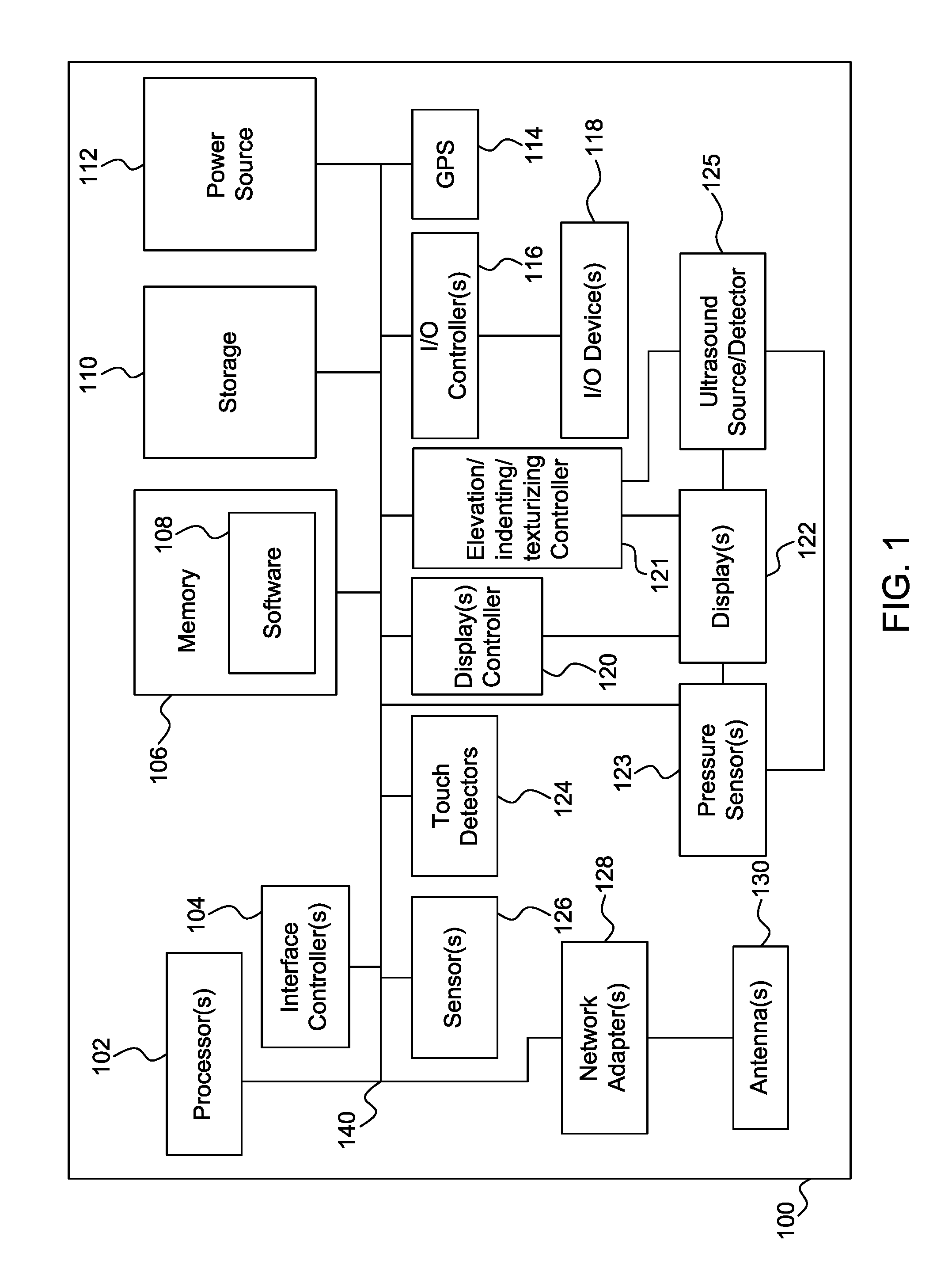
FIG. 1 is a diagram of an electronic device having a display device providing elevated, indented, or texturized sensations to an object near the display device using ultrasound in accordance with one embodiment;
FIGS. 2a-2d and 2f are diagrams of configurations for providing elevated, indented, or texturized sensations to an object using ultrasound in accordance with another embodiment;
FIG. 2e is a diagram of various ultrasound focal point patterns in accordance with another embodiment;
FIG. 3 is a diagram comprising of processes for an electronic device providing elevated, indented, or texturized sensations to an object near a display device using ultrasound in accordance with another embodiment;
FIG. 4 is a diagram for providing varying ultrasound strengths to an object for providing elevated, indented, or texturized sensations in accordance with another embodiment; and
FIG. 5 is a process for providing elevated, indented, or texturized sensations to an object near a display device using ultrasound in accordance with another embodiment.
DETAILED DESCRIPTION
The present invention will be described with reference to the drawing figures wherein like numerals represent like elements throughout. For the processes described below the steps recited may be performed out of sequence and sub-steps not explicitly described or shown may be performed. In addition, "coupled" or "operatively coupled" may mean that objects are linked between zero or more intermediate objects.
In the examples forthcoming ultrasound or ultrasonic waves are given as an example to provide elevated, indented, or texturized sensation to an object near a display device. However, one of ordinary skill would appreciate that any acoustic or radio wave that excites an afar object or sensed by the human body may be applicable for the examples and processes given in the disclosure.
In the examples forthcoming, the sensation felt by an object via an airborne ultrasound may be similar to vibration or gyration. The sensation may be varied by producing focal points of different sizes and intensities. For the case where the object is human skin, the vibration or gyration caused by an airborne ultrasound may depend on the targeted receptors in the skin. Adapting or controlling the ultrasound focal or control points for different receptors may cause different sensations for the user's skin.
Elevation or elevated sensations describe different sensations that may be caused to an object using ultrasound at a predetermined or random distance from a display or electronic device. As an example, the relative distance of the object may be by one or more millimeters to several meters, as desired.
Indenting may be a configuration where an object is given a sensation around its perimeter while giving little sensation to the inner area of the object. Indenting may also describe a configuration where a given location in space near a display device provides a substantially sensible ultrasound to an object but a point lower or closer to the display device the ultrasound is not substantially sensible. Indenting may also describe a configuration where a given location in space near a display device provides a substantially sensible ultrasound to an object but a point lower or closer to the display device an ultrasound is not substantially sensible until a predetermined point near the display device is reached.
Texturizing or texturing describes a process where an electronic device using controlled ultrasound over air may provide, simulate, or mimic friction, pulsing sensation, pulsating sensation, variable smoothness, variable thickness, coarseness, fineness, irregularity, a movement sensation, bumpiness, or rigidness that is sensed by or detectable by an object.
U.S. application Ser. No. 12/406,273 is herein incorporated by reference as if fully set forth and may be used in combination with the given examples to provide a display device that is elevated, indented, or texturized and ultrasound is used to provide a sensation to an object near the display device.
FIG. 1 is a diagram of a wireless subscriber unit, user equipment (UE), mobile station, pager, cellular telephone, personal digital assistant (PDA), computing device, surface computer, tablet computer, monitor, general display, versatile device, automobile computer system, vehicle computer system, or television device 100 for mobile or fixed applications. Device 100 comprises computer bus 140 that couples one or more processors 102, one or more interface controllers 104, memory 106 having software 108, storage device 110, power source 112, and/or one or more displays controller 120. In addition, device 100 comprises an elevation, indenting, or texturizing controller 121 to provide sensations an object located near one or more display devices 122.
One or more display devices 122 can be configured as a liquid crystal display (LCD), light emitting diode (LED), field emission display (FED), organic light emitting diode (OLED), or flexible OLED display device. The one or more display devices 122 may be configured, manufactured, produced, or assembled based on the descriptions provided in US Patent Publication Nos. 2007-247422, 2007-139391, 2007-085838, or 2006-096392 or U.S. Pat. No. 7,050,835 or WO Publication 2007-012899 all herein incorporated by reference as if fully set forth. In the case of a flexible display device, the one or more electronic display devices 122 may be configured and assembled using organic light emitting diodes (OLED), liquid crystal displays using flexible substrate technology, flexible transistors, or field emission displays (FED) using flexible substrate technology, as desired. One or more display devices 122 can be configured as a touch screen display using resistive, capacitive, surface-acoustic wave (SAW) capacitive, infrared, strain gauge, optical imaging, dispersive signal technology, acoustic pulse recognition, frustrated total internal reflection or magneto-strictive technology, as understood by one of ordinary skill in the art.
Coupled to one or more display devices 122 may be pressure sensors 123. Coupled to computer bus 140 are one or more input/output (I/O) controller 116, I/O devices 118, GPS device 114, one or more network adapters 128, and/or one or more antennas 130. Device 100 may have one or more motion, proximity, light, optical, chemical, environmental, moisture, acoustic, heat, temperature, radio frequency identification (RFID), biometric, face recognition, image, photo, or voice recognition sensors 126 and touch detectors 124 for detecting any touch inputs, including multi-touch inputs, for one or more display devices 122. One or more interface controllers 104 may communicate with touch detectors 124 and I/O controller 116 for determining user inputs to device 100.
Ultrasound source/detector 125 may be configured in combination with touch detectors 124, elevation, indenting, or texturizing controller 121, one or more display devices 122, pressure sensors 123, or sensors 126 to project or generate ultrasound waves, rays, or beams to an object to simulate elevated, indented, or texturized sensations, recognize inputs, or track the object as will be explained in more detail below. There may be cases for input recognition or object tracking wherein an ultrasound is provided without detected sensation to the object.
Still referring to device 100, storage device 110 may be any disk based or solid state memory device for storing data. Power source 112 may be a plug-in, battery, solar panels for receiving and storing solar energy, or a device for receiving and storing wireless power as described in U.S. Pat. No. 7,027,311 herein incorporated by reference as if fully set forth. One or more network adapters 128 may be configured as a Time Division Multiple Access (TDMA), Code Division Multiple Access (CDMA), Orthogonal Frequency-Division Multiplexing (OFDM), Orthogonal Frequency-Division Multiple Access (OFDMA), Global System for Mobile (GSM) communications, Enhanced Data rates for GSM Evolution (EDGE), General Packet Radio Service (GPRS), cdma2000, wideband CDMA (W-CDMA), long term evolution (LTE), 802.11.times., Wi-Max, mobile Wi-MAX, Bluetooth, or any other wireless or wired transceiver for modulating and demodulating information communicated via one or more antennas 130. Additionally, any of devices, controllers, displays, components, etc. in device 100 may be combined, made integral, or separated as desired. For instance, elevation, indenting, or texturizing controller 121 may be combined with ultrasound source/detector 125 in one unit.
FIGS. 2a-2d are diagrams of configurations for providing elevated, indented, or texturized sensations to an object using ultrasound. In FIG. 2a display device layer 204 lays proximate to ultrasound layer 205. Although a single layer is shown, layers 204 and 205 can be composed of a plurality of sublayers. Although display device layer 204 is shown above that ultrasound layer 205, some or most of the components of ultrasound layer 205, such as ultrasound transducer or detectors, may be provided in substantially the same level plane as display device layer 204. Display device layer 204 can be either a flexible or rigid display device for displaying video, images, photos, graphics, text, etc.
Ultrasound layer 205 can be configured and composed of ultrasound transducer, source, or detector devices as described in "Two-dimensional scanning tactile display using ultrasound radiation pressure" by Shinoda et al. (2006), "A Tactile Display using Ultrasound Linear Phased Array" by Shinoda et al. (2004), or "Small and Lightweight Tactile Display(SaLT) and Its Application" by Kim et al. (2009) that are all herein incorporated by reference as if fully set forth. As indicated by the incorporated references, linear phased arrays of ultrasound can provide at least 1 mm diameter focal or control points for fine, precise tactile airborne stimuli at variable frequencies and intensities. Larger focal points may also be provided. Techniques for tracking or detecting motion of a focal or control point and object may include Time Delay of Arrival (TDOA) where the difference in arrival times and the velocity of an ultrasound at one or more detectors is used to establish and track location. Airborne refers to an ultrasound transmission that may propagate through the air for at least a predetermined distance.
As previously stated, stimuli can be provided to an object by transmitting one or more ultrasound focal points to cause a vibration, gyration, beat, or tap by a phased array. The ultrasound intensity may be varied to cause different feelings to the object. Varying of sensations may also be done by changing focal point sizes.
Ultrasound layer 205 comprises of an array of coupled ultrasound transducers and/or detectors that may emit directional ultrasound waves, rays, or beams through air to objects at location points 206, 208, and/or 210 in sensation zone 202. Layer 205 also detects reflections of the emitted waves off of the objects at location points 206, 208, and/or 210. Layer 205 is controlled in part by elevation, indenting, or texturizing controller 121. Sensation zone 202 may be the space, part of the space, or a force field above display device layer 204 that defines the range of ultrasound perception. Sensation zone 202 may be defined using approximate boundaries in order to limit the space ultrasound are emitted over display device layer 204 for safety or power conservation. Another benefit of having sensation zone 202 is that a user can have space in other areas of display device layer 204 for normal operation of device 100.
In addition to providing airborne ultrasound in the direction of the user, ultrasound layer 205 may be configured with transducers and detectors directed away from the user. This double-sided configuration is desirable to provide ultrasound sensations to fingers placed behind device 100 for grasping in mobile applications. Airborne ultrasound zone behind device 100 may be used to give a user the ability to virtually grasp from afar images on screen perpendicular to device 100.
Objects at location points 206, 208, and/or 210 may be any one of a finger, part of a finger, a hand, part of a hand, skin, any body part, a special ultrasound sensitive glove, part of a special ultrasound sensitive glove, an ultrasound sensitive finger attachment, an ultrasound sensitive thimble, an ultrasound sensitive wand, a material that reacts in response to ultrasound, or a material that is perceptive to ultrasound, as desired.
FIG. 2b is a diagram showing various approximate airborne ultrasound patterns 222, 224, 226, and 228 emitted over display device surface 231. Substantially cubicle pattern 222 may be provided by emitting rays by ultrasound layer 205 to provide a substantially cubicle sensation. FIG. 2e shows an example of a focal point pattern 222.sub.1 for providing a substantially cubicle pattern sensation on finger 222.sub.2 by ultrasound layer 205. Ultrasound control or focal points shown in FIG. 2e or other figures are not drawn to scale and may be approximate in size. Dot or dimple pattern 224 may be provided by emitting rays by ultrasound layer 205 to provide a substantially spherical sensation. FIG. 2e shows an example of a focal point pattern 224.sub.1 for a dot or dimple pattern on finger 224.sub.2 emitted by ultrasound layer 205 to provide a substantially spherical sensation.
Moreover, substantially cylindrical pattern 226 may be provided by emitting rays by ultrasound layer 205 to provide a substantially circular sensation. FIG. 2e shows an example of a focal point pattern 226.sub.1 for a cylindrical pattern sensation on finger 226.sub.2 provided by ultrasound layer 205 to provide a substantially circular sensation.
Substantially rectangular pattern 228 may be provided by emitting rays by ultrasound layer 205 to provide a substantially rectangular sensation. FIG. 2e shows an example of focal point edge patterns 228.sub.1 and 228.sub.2 for a rectangular pattern sensation on finger 228.sub.3 provided by ultrasound layer 205. Although two edges are shown on finger 228.sub.3, a single or multiple edges may be projected. Edge projections are desirable for virtual keyboard applications where the projected edges help to define the boundaries of a key.
In the examples given in FIG. 2b ultrasound layer 205 may be controlled in part by ultrasound source/detector 125 in combination with elevation, indenting, or texturizing controller 121. In FIG. 2e, the ultrasound may be swept or stroked over each focal or control point in a pattern at high frequency or variable pulsating frequencies using various intensities levels dependent upon the desired sensation or virtual effect. Although well-defined shapes are shown in the FIGS. 2b and 2e, actual sensations will vary from person to person and by the accuracy of the phased array ultrasound source.
FIG. 2c is a diagram providing an example configuration of display device layer 204 and ultrasound layer 205. Display pixels 232.sub.1 to 232.sub.n may lay partially adjacent, on the same level, or on the same layer to elevation, indenting, or texturizing cells 234.sub.1 to 234.sub.n each having an ultrasound transducer, source, and/or detector. Alternatively, display pixels 232.sub.1 to 232.sub.n may lay partially above elevation, indenting, or texturizing cells 234.sub.1 to 234.sub.n. Display and ultrasound array or matrix 233 also comprises of display pixels 236.sub.1 to 236.sub.n adjacent to elevation, indenting, or texturizing cells 238.sub.1 to 238.sub.n that are adjacent to display pixels 240.sub.1 to 240.sub.n. The elevation, indenting, or texturizing cells may be controlled by elevation, indenting, or texturizing controller 121 to adjust the intensity, orientation, or direction of the ultrasound emitted to location points 206, 208, or 210.
FIG. 2d shows an embodiment of a display device array or matrix 235 from a top view where ultrasound transducer, source, or detector cells 239 and 241 are placed selectively within two predetermined areas without display pixels so that the surface of display device array or matrix 235 is mostly comprised of display pixels 237. In an alternative embodiment, cells 239 and 241 may line the perimeter of display device array or matrix 235. When around the perimeter, integration with existing display device layout may be more easily enabled.
FIG. 3 is a diagram comprising of processes for an electronic device providing elevated, indented, or texturized sensations to an object near display device 302 using ultrasound. For the examples given in FIG. 3, the object provided elevated, indented, or texturized sensations near display device 302 using ultrasound may be any one of a finger, part of a finger, multiple fingers, a hand, part of a hand, or two hands as desired. Display device 302 may be assembled with at least some of the components described in device 100.
For inputting or triggering a request action, a "click here" displayed universal resource locater (URL) or hyperlink is provided to an object that may be at location points 206, 208, and/or 210 with an elevated substantially circular ultrasound pattern 304. Clicking may be performed by tracking the motion, momentum, or velocity of the object as provided in the example in FIG. 5 below. Motion of the object relative to display device 302 that can be recognized as an input, gesture, or command may be a push towards display device 302, a pull away from display device 302, sideway or lateral motion relative to display device 302, a circle gesture, a square gesture, a rectangular gesture, a spiral gesture, a swirl gesture, a swipe gesture, a pinch gesture, a flick gesture, a customized gesture, a user defined gesture, a multiple finger coordinated motion, or a single finger gesture, as desired. In particular, single finger gesture control is desirable since the user may use for example the thumb finger for gestures to signal an input or command while holding device 100 at the same time for mobile applications allowing the other hand to be free. Gestures may be stored in a gesture library or database in storage device 110.
In addition to gestures, tracking an object relative to display device 302, as provided in an example in FIG. 5, may be used for drawing purposes. A user may use a finger to draw in air a character or shape that is detected by ultrasound source/detector 125 and rendered into an image by one or processors 102. This feature may be useful, for instance, in computer games, toys, or graphics applications.
In FIG. 3, part of an on screen virtual or simulated keyboard displayed on display device 302 provides the letter "E" key having an elevated substantially square ultrasound 308 provided to an object at location points 206, 208, and/or 210. Although part of a virtual or simulated keyboard is shown, display device 302 can be configured to show a whole QWERTY keyboard, a numeric keypad, or a combination of a whole QWERTY keyboard and a numeric keypad, as desired. The letter "S" key is provided by a partially displayed portion and an elevated substantially circular ultrasound 310. The virtual or simulated keyboard may also be programmed to replicate Braille lettering, as desired.
As an example, for letters "Q" and "A" ultrasound 306.sub.1 and 306.sub.2 are projected around the perimeter or edges of the keys to define boundaries so that a user may type the correct key and can find or feel the correct position of the keys. For displayed letters "Q" and "A" a user may type the key by physically touching display device 302. The touch input is detected by touch detectors 124.
In one embodiment a pull away motion of an object from display device 302 may be detectable as a capital or superscripting letter input while a push motion in the direction towards the display device may indicate subscripting of the letter. In response to a detected motion, haptic feedback, force feedback, or tactile feedback in the form of a played sound, gyration, or vibration may be provided via I/O controller 116.
Referring to FIG. 4, chart 400 shows an example of how ultrasound focal or control point strength or intensity units may be varied over time to provide different sensations to a user's finger, hand, or any other object. For instance, as a user pulls a finger away from display device 302, which is detected by ultrasound source/detector 125, strength or intensity units may be reduced by elevation, indenting, or texturizing controller 121. Conversely, when the finger is pushed towards display device 302 strength or intensity units may be increased for a predetermined period creating a virtual feeling of resistance.
In addition to inputting information via an on screen virtual or simulated keyboard shown in FIG. 3, display device 242 may project ultrasound as shown in FIG. 2f. Ultrasound transducer, source, or detector cells 244 may project onto zone 246 so that the user's view of display device 242 is unobstructed. Zone 246 may be projected onto a table or desk giving the user the ability to use the space as an input area similar to that of a keyboard or mouse. A special pad 248 may be used to reflect or vibrate in response to ultrasound from transducer, source, or detector cells 244.
Referring again to the virtual or simulated keyboard on display device 302, instructions in software 108 can be used to predict or anticipate keystrokes. Prediction or anticipation may be based on a word or sentence entered. In response to the anticipation, a different key may emit ultrasound to a user's finger, hand, or any other object to encourage or invoke input and provide context awareness.
An embodiment of the present invention may provide enhanced electronic advertising processes. Advertisement 316, such as an adword by Google, can be sold to an advertiser for a certain price for having elevated substantially circular ultrasound 317 on at least one part or the entire advertisement image or photo. Advertisement 318 can be sold to an advertiser for a different price, higher or lower, for having elevated substantially circular ultrasound 318.sub.1 and 318.sub.2 each projected at a different intensity in comparison to substantially circular ultrasound 317. In addition, the strength or intensity of substantially circular ultrasound 317, 318.sub.1, and 318.sub.2 may be dependent on location determined by GPS device 114 and varied over time as shown in FIG. 4.
Advertisement 316 or 318 may be provided in a separate pop up window with the emitted ultrasound to an object at location points 206, 208, and/or 210. The emitted ultrasound may be provided only for a predetermined time period after the pop up window is displayed thereby providing a nudge or feeling sensation to the object. As the pop up window emerges the intensity of ultrasound to the object may be increased over time prior to turning off thereby simulating the effect of the pop up window virtually emerging from display device 302.
With advertisement 316 or 318 in a separate pop up window, or for any another application in a window, a user may interact with an operating system by moving windows, grabbing windows, dragging windows, or dropping windows. Substantially circular ultrasound 317, for instance, may provide to a user's fingers a sensation by projecting multiple focal or control points when the user virtually tries to grab a window shown on display device 302. As the user moves a window, a slight vibration is provided by substantially circular ultrasound 317. A strong vibration may be provided by substantially circular ultrasound 317 when running into obstacles or boundaries on the screen. The vibration may stop when the user releases the window, as desired.
An embodiment of the present invention may provide electronic commerce processes. A "Buy Now" button is provided with an elevated substantially circular ultrasound 322.sub.1 and an elevated substantially square ultrasound 322.sub.2 to an object at location points 206, 208, and/or 210. The "Buy Now" button is associated with triggering the purchasing of displayed shirt 324 by sending a request to a server (not shown) over one or more network adapters 128. For shirt 324, ultrasound texturizing pattern 326 is provided to virtually replicate or simulate the surface or composition of shirt 324. Ultrasound texturizing pattern 326 can be a combination of different ultrasound focal or control points. Although a shirt 324 is shown, ultrasound texturizing pattern 326 can be used to provide surface information for any product being sold or displayed on display device 302.
Using touch detectors 124 in combination with elevation, indenting, or texturizing controller 121, displayed shirt 324 can be highlighted and then rotated in response to a multitouch input while ultrasound texturizing pattern 326 is dynamically changed to virtually reflect the different surfaces or materials used to make the shirt. Shirt 324 can be zoomed in and out using mulitouch inputs detected by touch detectors 124 with each zoom level reflecting texture differences on ultrasound texturizing pattern 326. For instance, a zoomed in view may be more grainy or rough compared to a zoomed out view. The zoom levels can also be configured with a fading in or out effect by one or more processors 102 and can involve retrieving additional information from a server (not shown) over one or more network adapters 128. Beyond the examples of fabrics, any material may be replicated or simulated by ultrasound texturizing pattern 326. Airborne ultrasound feedback, similar to multitouch inputs, may also be used to change views, angles, or size of displayed shirt 324.
Still referring to displayed shirt 324, display device 302 may be elevated, indented, or texturized in accordance with examples given in U.S. application Ser. No. 12/406,273. With shirt 324 texturized on display device 302 and at a distance to an object using ultrasound, the user is given an improved realization of the composition of the shirt by combining the two enhancements.
Referring again to FIG. 3, an embodiment of the present invention provides an electronic game, such as tic-tac-toe, by projecting ultrasound pattern 328 to an object at location points 206, 208, and/or 210. As an example given in gaming applications, ultrasound pattern 328 may be projected to multiple fingers and tracked as the user tries to pinch, grab, or push an object in a game or any other simulated environment displayed on display device 302. Ultrasound pattern 328 emitted onto an object can also control scrolling or drag and drop functions of items in a game in combination with multitouch inputs detected by touch detectors 124.
In another example, ultrasound pattern 328 can be controlled by elevation, indenting, or texturizing controller 121 such that an object being tracked at location point 206, such as user's hand, can be handed off or switched to location point 208, such as a user's other hand, to be tracked. Using this process, for instance, a user may dribble a ball from one hand to another in front of display device 302. Moreover, passing of location points in space and time from 206 to 208, results in passing a location point of an object between different horizontal planes relative to display device layer 204. Alternatively, the location point may be passed on the same plane.
In another example, ultrasound pattern 328 can be used to emulate a spring like sensation to an object and simulate elasticity to a user's hand in a game or any other application. Ultrasound layer 205 can also simulate whole screen explosions, blasts, or bullets being fired at the user by turning on several ultrasound transducers for a predetermined period of time in a game or movie. Ultrasound pattern 328 may also provide a gaming feature where tilting or rotation detected by an accelerometer in sensors 126 controls ultrasound output for four dimensional motion gaming. Ultrasound pattern 328 may also define the boundaries of a virtual space or layer between location points 206, 208, and 210 and display device layer 204.
In another embodiment, ultrasound pattern 328 projected onto multiple fingers can be used to simulate a virtual joystick or pointing stick for 360 degrees rotational input by tracking the movement of the fingers by ultrasound source/detector 125. A three dimensional accelerometer can be included in sensors 126 to be used in combination with elevation, indenting, or texturizing controller 121 to project ultrasound pattern 328 in response to a programmed action in the game. Similarly, a visual haptic ultrasound mouse or track pad may be configured by projecting and controlling ultrasound pattern 328 to replicate the functionality of a mouse or track pad and provide a 4-D free space tactile user interface device.
In another embodiment, ultrasound pattern 328 can provide enhanced features for online collaboration, distance learning, online conferencing, social networking, or online dating. For instance, in response to push command on a networked computing device (not shown), which may or may not have an ultrasound enhanced display device, ultrasound pattern 328 may provide feedback to an object at location points 206, 208, and/or 210. Examples of feedback are a poke sensation similar to that on Facebook, a push sensation, a virtual handshake sensation, etc. In online conferencing, tactile inputs or gestures via ultrasound pattern 328 may be used during a video conference application for additional interaction between conversing parties. Social networking or adult entertainment applications can be enhanced by ultrasound pattern 328 providing stimulation in connection with a video, image, photo, or audio media on display device 302.
For digital imagery, ultrasound rays 327.sub.1 and 327.sub.2 may be used to augment, enhance, or characterize different objects in photo or image 327.sub.3. Ultrasound rays 327.sub.1 and 327.sub.2 may be preprogrammed into photo or image 327.sub.3 by the owner for watermarking, artistic design, or the like. Ultrasound 327.sub.1 and 327.sub.2 may also be used to augment photo editing applications. If display device 302 is configured as a digital sign, ultrasound 327.sub.1 and 327.sub.2 may be used to get the attention of people walking near or viewing the photo or image 327.sub.3 on the sign.
In addition, ultrasound pattern 328 may also project sensations to simulate maps, topography, geography, imagery, or location service processes in combination with GPS device 114. Ultrasound pattern 328 can simulate mountainous regions on a map by projecting an ultrasound of various heights and intensities to an object at location points 206, 208, and/or 210.
Ultrasound pattern 328 may also be used to simulate the action of picking up (i.e. cut) or drop text (i.e. paste) in an email, 3rd Generation Partnership Project (3GPP) or 3GPP2 short message service (SMS) text message, or 3GPP/3GPP2 multimedia message service (MMS) message. Ultrasound pattern 328 may also be used in connection with a PDF document, word document, excel, four dimensional (4-D) screensaver, 4-D art, 4-D drawings, 3-D imagery, a 3-D sculpture, a 4-D "etch-a-sketch", or architecture designs using scalable or vector graphics. Any of the actions given above for ultrasound pattern 328 may be used in combination with transmitting or receiving information over one or more network adapters 128.
In e-book applications, ultrasound pattern 328 can be used to replicate or simulate the edge of a page and allow a user to virtually lift or pick-up a page. Moreover, a user may be able to feel text of varying sensations provided by ultrasound pattern 328 that is hyperlinked or highlighted on an e-book page as the user moves a finger across the page.
For multitouch applications, airborne ultrasound pattern 328 may be used to simulate friction or resistance as a user moves an image by touching the screen, zooms into an image, or zooms out of an image. When zooming beyond a threshold, ultrasound pattern 328 can be used to provide resistance thereby defining boundaries and providing a warning or alarm. While scrolling, panning, or gliding, hitting a threshold level or endpoint causes an ultrasound tactile feedback or response. For scrolling momentum, the ultrasound pattern 328 may provide high intensity initially to simulate inertia and then less intensity as momentum builds. For navigating through a list of items on display device 302, items may be highlighted on the screen as the user scrolls through the list from afar.
Moreover, display device 302 may have ultrasound source/detectors 330.sub.1-330.sub.4 in a slightly beveled position or in the level with the frame of display device 302. Display device 302 may also have digital image or infrared cameras 334.sub.1-334.sub.4 for tracking motion of objects at location points 206, 208, and/or 210 using algorithms such as that described in U.S. Pat. No. 7,317,872, herein incorporated by reference as if fully set forth, that can be used to perform additional sensor measurements. Other sensor measurements for additional metrics and refinement include infrared or optical detection to detect depth of objects at location points 206, 208, and/or 210. These sensors can be embedded next to or within each display cell in display device 302.
In another embodiment, display device 302 replicates, mimics, or simulates a customizable or programmable interface or control panel for a remote control, instrument panel on a vehicle, an automobile dashboard configuration, audio equalizers, multitouch equalizers, radio button list, or a consumer electronics button surface with ultrasound patterns 332.sub.1-332.sub.3. For demoing consumer electronics online, ultrasound patterns 332.sub.1-332.sub.3 provide a user the ability to simulate buttons on a device prior to purchase or use as a tutorial. Moreover, 332.sub.1-332.sub.3 can be programmed for controlling volume control, replicating smart home switches or controllers, or replicating a dial or knob, as desired.
Still referring to FIG. 3, ultrasound may be used to feel, sense, or move text, images, photos, windows or icons. For instance, web searching is performed by dragging and dropping text "TEST SEARCH" 337 into search box 336. A user may be provided substantially circular ultrasound 338 when grabbing the text "TEST SEARCH" from a distance to display device 302. The user then moves or drags the text "TEST SEARCH" from afar via path 339 over to search box 336 and releases or drops it. The user's finger movements are tracked by ultrasound source/detector 125 in combination with elevation, indenting, or texturizing controller 121. The text may be shown as moving on display device 302 as the user's fingers are tracked. Similarly a visual, photo, or image search may be performed by grabbing image of shirt 324 and dropping it in search box 336.
In another example, ultrasound pattern 328 can be used to replicate or simulate a virtual stylus, pen, or pencil allowing a user to mimic writing or drawing on display device 302 similar to a notepad. The virtual stylus, pen, or pencil may be configured without the user physically holding anything. Unlike a notepad, the writing or drawing may be done at a predetermined distance from display device 302 in sensation zone 202.
Ultrasound pattern 328 can also be used for medical applications. For instance, with lap aroscopic surgery a physician located in the surgery room or remote to the surgery room may be able to feel or sense images or photos of organs of a patient provided by an internal surgical camera and displayed on display device 302. Ultrasound pattern 328 may also be used to simulate pain of a patient to a doctor over the Internet.
In another example, ultrasound pattern 328 can be responsive to voice or visual commands or recognition detected by sensors 126. Alternatively, ultrasound pattern 328 can be a preprogrammed texturized pattern to notify the user of an incoming call, similar to a customized ringtone. Alternatively, ultrasound pattern 328 may be used for providing a warning to a driver in relation to safety feature on an automobile. Alternatively, ultrasound pattern 328 may be used for enhancing icons on a system tray with each icon having a different characteristic vibration sensation. Alternatively, device 100 may be controlled remotely, either wired or wirelessly, via a server or cloud computing platform (not shown) via one or more network adapters 128.
Moreover, ultrasound pattern 328 can be used to replicate, simulate, enhance features for biometrics, musical instruments, video clips, editing audio tracks, editing video, computer aided designs (CAD), semiconductor layouts, e-books, a children's educational product, children's productivity or educational game, a general education product, a 3-D drawing tool, distance learning, or a pop-up children's books, as desired.
FIG. 5 is a process 500 for providing elevated, indented, or texturized sensations to an object near a display device using ultrasound. In the example given here, the object may be one or more fingers or hands at location points 206, 208, and/or 210. Ultrasound source/detector 125 determines the initial object location and calculates a distance and angle relative to display device 302 (step 502) to calculate focal or control point vectors. For initialization, a user's fingers, hand, or a predetermined object may be place over a predetermined zone over display device 302. Alternatively, a user's fingers, hand, or a predetermined object may be detected by digital or infrared cameras 334.sub.1-334.sub.4 using image or photo recognition technology. Once the location of the object is determined, device 100 may display a preprogrammed image, such as a virtual keyboard or icon, on display device 302 at the detected location.
Ultrasound source/detector 125 in combination with elevation, indenting, or texturizing controller 121 projects or emits one or more ultrasound patterns, such as the ones shown in FIG. 2e, having one or more focal or control points (step 504). In order to project a predetermined sensation, the intensity of ultrasound at one or more focal or control points may be varied. Also, in the case of multiple objects ultrasound source/detector 125 may be time multiplexed to project different ultrasound patterns to each object. Elevation, indenting or texturizing controller 121 focuses or adjusts focal or control point vectors (step 506). Ultrasound source/detector 125 in combination with elevation, indenting or texturizing controller 121 detects, tracks, or senses movement of focal or control points to determine momentum and/or velocity of an object (step 508). While the object moves and is tracked, the ultrasound patterns provided to the object may vary based on images, text, video, or the like displayed on display device 302.
In order to enhance accuracy or user experience, device 100 may detect and track multitouch inputs by other fingers and/or input detected by other sensors (step 510). An animation or video of a generated surface may be displayed on display device 302 for feedback and showing the tracking of the object (step 512). If an input, gesture, or command is recognized by ultrasound source/detector 125 in combination with elevation, indenting or texturizing controller 121 (step 514), the input, gesture, or command is processed by one or more processors 102 (step 516) and information is retrieved based on the input, gesture, or command (step 518).
Although features and elements are described above in particular combinations, each feature or element can be used alone without the other features and elements or in various combinations with or without other features and elements. The methods, processes, or flow charts provided herein may be implemented in a computer program, software, or firmware incorporated in a computer-readable storage medium for execution by a general purpose computer or a processor. Examples of computer-readable storage mediums include a read only memory (ROM), a random access memory (RAM), a register, cache memory, semiconductor memory devices, magnetic media such as internal hard disks and removable disks, magneto-optical media, and optical media such as CD-ROM disks, digital versatile disks (DVDs), and BluRay discs.
Suitable processors include, by way of example, a general purpose processor, a special purpose processor, a conventional processor, a digital signal processor (DSP), a plurality of microprocessors, one or more microprocessors in association with a DSP core, a controller, a microcontroller, Application Specific Integrated Circuits (ASICs), Field Programmable Gate Arrays (FPGAs) circuits, any other type of integrated circuit (IC), and/or a state machine.
A processor in association with software may be used to implement hardware functions for use in a computer, wireless transmit receive unit (WTRU) or any host computer. The programmed hardware functions may be used in conjunction with modules, implemented in hardware and/or software, such as a camera, a video camera module, a videophone, a speakerphone, a vibration device, a speaker, a microphone, a television transceiver, a hands free headset, a keyboard, a Bluetooth.RTM. module, a frequency modulated (FM) radio unit, a liquid crystal display (LCD) display unit, an organic light-emitting diode (OLED) display unit, a digital music player, a media player, a video game player module, an Internet browser, and/or any wireless local area network (WLAN) or Ultra Wide Band (UWB) module.
* * * * *
References
D00000
D00001
D00002
D00003
D00004
D00005
D00006
D00007
XML
uspto.report is an independent third-party trademark research tool that is not affiliated, endorsed, or sponsored by the United States Patent and Trademark Office (USPTO) or any other governmental organization. The information provided by uspto.report is based on publicly available data at the time of writing and is intended for informational purposes only.
While we strive to provide accurate and up-to-date information, we do not guarantee the accuracy, completeness, reliability, or suitability of the information displayed on this site. The use of this site is at your own risk. Any reliance you place on such information is therefore strictly at your own risk.
All official trademark data, including owner information, should be verified by visiting the official USPTO website at www.uspto.gov. This site is not intended to replace professional legal advice and should not be used as a substitute for consulting with a legal professional who is knowledgeable about trademark law.