Bracket for product display grid and related methods
Wills , et al. Nov
U.S. patent number 10,470,590 [Application Number 15/896,681] was granted by the patent office on 2019-11-12 for bracket for product display grid and related methods. This patent grant is currently assigned to Retail Space Solutions LLC. The grantee listed for this patent is Retail Space Solutions LLC. Invention is credited to Craig A. Fluegge, Eric Pollpeter, Matthew Wills.


| United States Patent | 10,470,590 |
| Wills , et al. | November 12, 2019 |
Bracket for product display grid and related methods
Abstract
A product display system comprising an upright structure, a first rectangular grid comprising a plurality of cross members, a first bracket coupled to the grid, and a second bracket coupled to the grid. The first bracket comprising, a first engagement structure configured to detachably couple to the grid, and a second engagement structure configured to detachably couple to the upright structure. The second bracket comprising a first engagement structure configured to detachably couple to the grid, and a second engagement structure configured to detachably couple to a second grid.
| Inventors: | Wills; Matthew (Grafton, WI), Fluegge; Craig A. (Menomonee Falls, WI), Pollpeter; Eric (Cedarburg, WI) | ||||||||||
|---|---|---|---|---|---|---|---|---|---|---|---|
| Applicant: |
|
||||||||||
| Assignee: | Retail Space Solutions LLC
(Milwaukee, WI) |
||||||||||
| Family ID: | 61231196 | ||||||||||
| Appl. No.: | 15/896,681 | ||||||||||
| Filed: | February 14, 2018 |
Prior Publication Data
| Document Identifier | Publication Date | |
|---|---|---|
| US 20180228303 A1 | Aug 16, 2018 | |
Related U.S. Patent Documents
| Application Number | Filing Date | Patent Number | Issue Date | ||
|---|---|---|---|---|---|
| 62459315 | Feb 15, 2017 | ||||
| Current U.S. Class: | 1/1 |
| Current CPC Class: | A47B 96/06 (20130101); A47F 5/0838 (20130101); A47F 5/103 (20130101); A47F 5/13 (20130101); A47F 5/0884 (20130101); A47F 5/083 (20130101); A47B 57/406 (20130101) |
| Current International Class: | A47F 5/08 (20060101); A47B 57/40 (20060101); A47F 5/10 (20060101); A47F 5/13 (20060101); A47B 96/06 (20060101) |
| Field of Search: | ;211/106,87.01,106.01,103 ;248/250,248,235,220.21,221.11,225.21 |
References Cited [Referenced By]
U.S. Patent Documents
| 2309851 | February 1943 | Kuhne |
| 3174592 | March 1965 | Berman |
| 3229823 | January 1966 | Hummer |
| 3294351 | December 1966 | Rollins, Jr. |
| 3486632 | December 1969 | Balch |
| 3495717 | February 1970 | Lavin |
| 3627247 | December 1971 | Krikorian |
| 3765344 | October 1973 | Ferdinand |
| 3779394 | December 1973 | Bard |
| 3779499 | December 1973 | Shell |
| 3853293 | December 1974 | Larson |
| 3886698 | June 1975 | Raith |
| 3897926 | August 1975 | Silver |
| D237142 | October 1975 | Barnes |
| 3966158 | June 1976 | Boundy |
| 4037729 | July 1977 | DeSisto |
| 4109797 | August 1978 | Brunette |
| 4127196 | November 1978 | Boucher |
| 4234094 | November 1980 | Jorgensen |
| 4340144 | July 1982 | Cousins |
| D267606 | January 1983 | Vrignaud |
| 4366906 | January 1983 | Joyce |
| 4401222 | August 1983 | Kulikowski |
| 4405051 | September 1983 | Thalenfeld |
| 4415091 | November 1983 | Wolff |
| 4467926 | August 1984 | Percival |
| 4501369 | February 1985 | Fox |
| 4509648 | April 1985 | Govang |
| 4542832 | September 1985 | Minick |
| 4550893 | November 1985 | Wiersema |
| 4583648 | April 1986 | Buffington |
| 4591057 | May 1986 | Garfinkle |
| D285168 | August 1986 | Van Arsdell |
| 4615503 | October 1986 | Garfinkle |
| 4735325 | April 1988 | Remmers |
| 4832298 | May 1989 | Metcalf |
| 4842230 | June 1989 | Cobb |
| 5031783 | July 1991 | Goudreau |
| 5038943 | August 1991 | Reinke |
| 5097968 | March 1992 | Gregory |
| 5188326 | February 1993 | Zich |
| 5236163 | August 1993 | Valiulis |
| 5253770 | October 1993 | Rosenthal |
| 5305898 | April 1994 | Merl |
| 5326062 | July 1994 | Remmers |
| 5351842 | October 1994 | Remmers |
| 5379976 | January 1995 | Degirolamo |
| 5398824 | March 1995 | Wolff |
| 5415370 | May 1995 | Valiulis |
| 5439120 | August 1995 | Brozak |
| 5472103 | December 1995 | Merl |
| 5482168 | January 1996 | Welch |
| 5526941 | June 1996 | Ford |
| 5641081 | June 1997 | Merl |
| 5769247 | June 1998 | Merl |
| 5769248 | June 1998 | Johnson |
| 5855283 | January 1999 | Johnson |
| 5868263 | February 1999 | McAllister |
| 5921411 | July 1999 | Merl |
| 6109461 | August 2000 | Kluge |
| 6241107 | June 2001 | Boyer |
| 6299001 | October 2001 | Frolov |
| 6471079 | October 2002 | Berlingieri |
| D467792 | December 2002 | Zadak |
| 6497331 | December 2002 | Morandi |
| 6497395 | December 2002 | Croker |
| 6688478 | February 2004 | Miller, Jr. |
| 6726035 | April 2004 | Zadak |
| 6746379 | June 2004 | Brawner |
| D502516 | March 2005 | Chen |
| D519359 | April 2006 | Hoernig |
| 7128223 | October 2006 | Sarnoff |
| D547164 | July 2007 | Xayoiphonh |
| 7270242 | September 2007 | Liu |
| D555466 | November 2007 | Hennig |
| 7334692 | February 2008 | Black |
| D564865 | March 2008 | Johnson |
| 7387213 | June 2008 | Smalley |
| 7497344 | March 2009 | Chen |
| 7954656 | June 2011 | Cuzzocrea |
| 8540088 | September 2013 | Brasher |
| 9119471 | September 2015 | Gonzalez |
| 9178343 | November 2015 | Brouwer |
| 2004/0084392 | May 2004 | Richter |
| 2005/0006541 | January 2005 | Magnusson |
| 2005/0056749 | March 2005 | Simard |
| 2006/0278782 | December 2006 | Lockwood |
| 2007/0023375 | February 2007 | Fedewa |
| 2007/0176065 | August 2007 | Schneider |
| 2007/0187561 | August 2007 | Xayoiphonh |
| 2008/0179267 | July 2008 | Johnson |
| 2010/0300999 | December 2010 | Schwartzkopf |
| 2012/0305504 | December 2012 | Currin |
| 2015/0313357 | November 2015 | David |
| 2017/0231388 | August 2017 | Will |
| 2018/0228303 | August 2018 | Wills |
| 567804 | Nov 1993 | EP | |||
| 3042865 | Jul 2016 | EP | |||
| 66717 | Aug 1957 | FR | |||
| 2004000073 | Dec 2003 | WO | |||
| 2015084866 | Jun 2015 | WO | |||
| 2016129669 | Aug 2016 | WO | |||
| 2016178610 | Nov 2016 | WO | |||
Other References
|
European Patent Office, Partial European Search Report issued in European Patent Application No. 18275020.8, dated Jun. 4, 2018, 9 pp. cited by applicant . Communication Pursuant to Article 94(3) EPC in corresponding European Application No. 18275020.8, dated Mar. 20, 2019. cited by applicant. |
Primary Examiner: Novosad; Jennifer E.
Attorney, Agent or Firm: Andrus Intellectual Property Law, LLP
Parent Case Text
CROSS REFERENCE TO RELATED APPLICATION
This application claims the benefit of U.S. Provisional Application No. 62/459,315, filed Feb. 15, 2017, which is hereby incorporated herein by reference in its entirety.
Claims
The invention claimed is:
1. A bracket comprising: a body having a first engagement structure and a second engagement structure wherein the first engagement structure is configured to connect to a grid structure and the second engagement structure is configured to connect to an upright structure; wherein the body is generally U-shaped having a first body portion positioned substantially parallel to a second body portion with the first and second body portions being interconnected via an intermediate body portion; wherein the first engagement structure comprises a plurality of substantially enclosed holes formed in at least one of the first and second body portions for receiving rod or bar ends of the grid structure; wherein the second engagement structure comprises at least one hook-shaped protrusion for engaging a mating slot in the upright structure and supporting the bracket therefrom, the at least one hook-shaped protrusion extending from at least one of the first body portion, the second body portion, and the intermediate body portion; and wherein the at least one hook-shaped protrusion comprises two recesses that open in opposite directions and are vertically aligned with one another.
2. The bracket of claim 1 wherein the first engagement structure is configured to detachably couple to the grid structure, the second engagement structure is configured to detachably couple to the upright structure, and the bracket further comprises a securing structure configured to increase friction between the first engagement structure and the grid structure.
3. The bracket of claim 2 wherein the securing structure comprises a deformable member positioned to be deformed by at least one of the rod or bar ends in response to the at least one of the rod or bar ends being disposed within at least one of the substantially enclosed holes.
4. The bracket of claim 1 further comprising an opening proximate at least one of the substantially enclosed holes and having a deformable securing structure disposed therein adapted to increase friction on at least one of the rod or bar ends disposed within the at least one of the substantially enclosed holes.
5. The bracket of claim 4 wherein the deformable securing structure is a plastic or rubber grommet that is aligned to overlap with the at least one of the substantially enclosed holes proximate the opening containing the deformable securing structure.
6. The bracket of claim 4 wherein the opening adjoins the at least one of the substantially enclosed holes, and the deformable securing structure extends at least partially into the at least one of the substantially enclosed holes.
7. The bracket of claim 1 wherein the substantially enclosed holes are formed in each of the first and second body portions, and each hole on the first body portion is aligned with a corresponding hole on the second body portion.
8. The bracket of claim 1 wherein the at least one hook-shaped protrusion extends from only one of the first and second body portions.
9. The bracket of claim 1 wherein the bracket is symmetrical about a horizontal centerline thereof.
10. A bracket comprising: a body having an engagement structure and at least one hook; wherein the engagement structure has at least one substantially enclosed hole sized to receive a cross member of a first grid structure; wherein the at least one hook is configured to connect to at least one of an upright structure and a second grid structure; and further comprising an opening adjoining the at least one substantially enclosed hole, the opening having a deformable securing structure disposed therein, the deformable securing structure extending at least partially into the at least one substantially enclosed hole and being adapted to increase friction on the cross member in response to the cross member being disposed at least partially within the at least one substantially enclosed hole.
11. The bracket of claim 10 wherein the engagement structure is configured to detachably couple to the first grid structure, and the at least one hook is configured to detachably couple to the upright structure.
12. The bracket of claim 10 wherein the deformable securing structure is a plastic or rubber grommet.
13. The bracket of claim 10 wherein the body is generally U-shaped having a first body portion positioned substantially parallel to a second body portion with the first and second body portions being interconnected via an intermediate body portion, with the engagement structure comprising a plurality of holes, including the at least one substantially enclosed hole, formed in each of the first and second body portions and each hole on the first body portion aligned with a corresponding hole on the second body portion, and further comprising a plurality of hooks, including the at least one hook, extending from at least one of the first body portion, the second body portion, and the intermediate body portion.
14. The bracket of claim 13 wherein the plurality of hooks extends from only one of the first and second body portions.
15. The bracket of claim 10 wherein the at least one hook comprises two recesses that open in opposite directions and are vertically aligned with one another.
Description
FIELD
This invention relates generally to product displays and, more particularly, to brackets for mounting grids for supporting product displays.
BACKGROUND
Product displays, such as merchandisers, are frequently used in retail environments to display products for sale. These product displays are frequently supported by wire grids or product display grids. Example product display grids are described in U.S. Pat. No. 5,769,248 "Product Display Grid System" assigned to DCI Marketing which is fully incorporated herein by reference. Wire grids are generally made of metal and are about 18 inches high and 48 inches wide. The grids are mounted to walls or uprights of a shelving system. Once the grids are mounted to the uprights, product displays are mounted to the grid. The grids sometime mounted to the uprights and/or wall by way of mounting brackets. Traditional brackets may be knocked off while trying to move the large, heavy grid into position. Additionally, the right side brackets may be accidentally placed to the left of the grid or vice versa.
It would be useful to have universal brackets capable of more firmly engaging grids in order to aid in grid installation.
BRIEF DESCRIPTION OF THE FIGURES
Embodiments of the invention are illustrated in the figures of the accompanying drawings in which:
FIG. 1 is a perspective view of a product display assembly according to a first embodiment of the present invention.
FIG. 2A is a front right perspective view of a bracket used in the assembly of FIG. 1.
FIG. 2B is a front left perspective view of the bracket of FIG. 2A.
FIG. 2C is a back left perspective view of the bracket of FIGS. 2A-2B.
FIG. 3A is a perspective view of a product display assembly according to a second embodiment of the present invention.
FIG. 3B is a front right perspective view of a bracket used in the assembly of FIG. 3A.
FIG. 3C is a front left perspective view of the bracket of FIG. 3B.
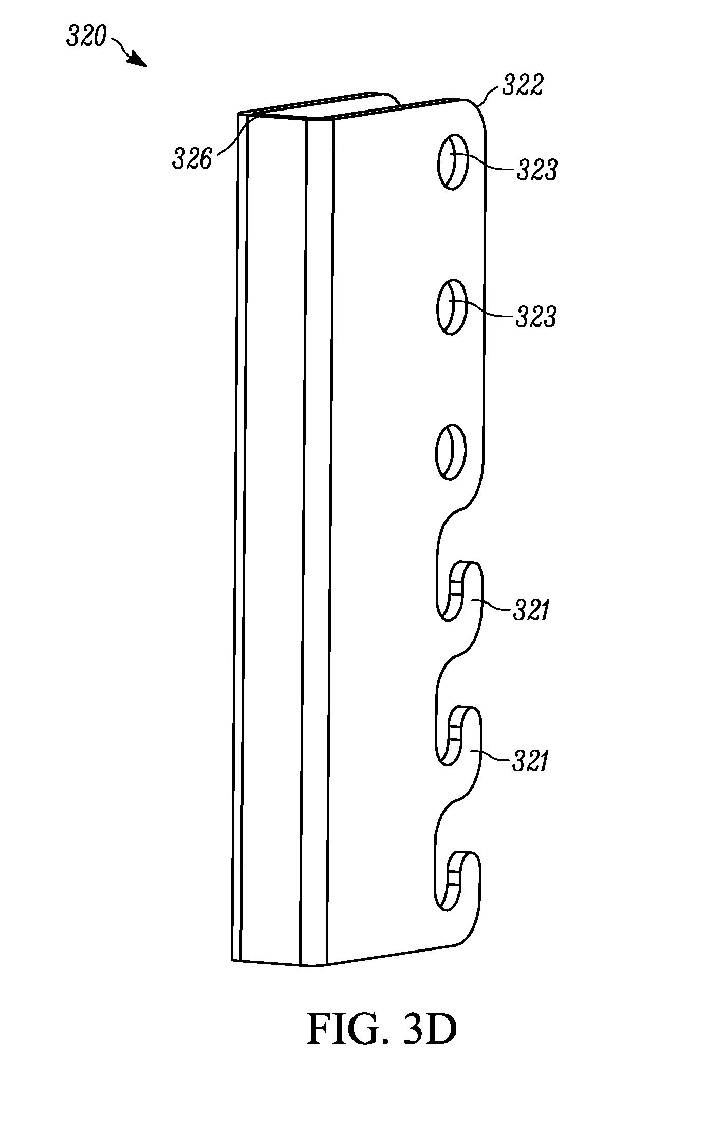
FIG. 3D is a back left perspective view of the bracket of FIGS. 3B-3C.
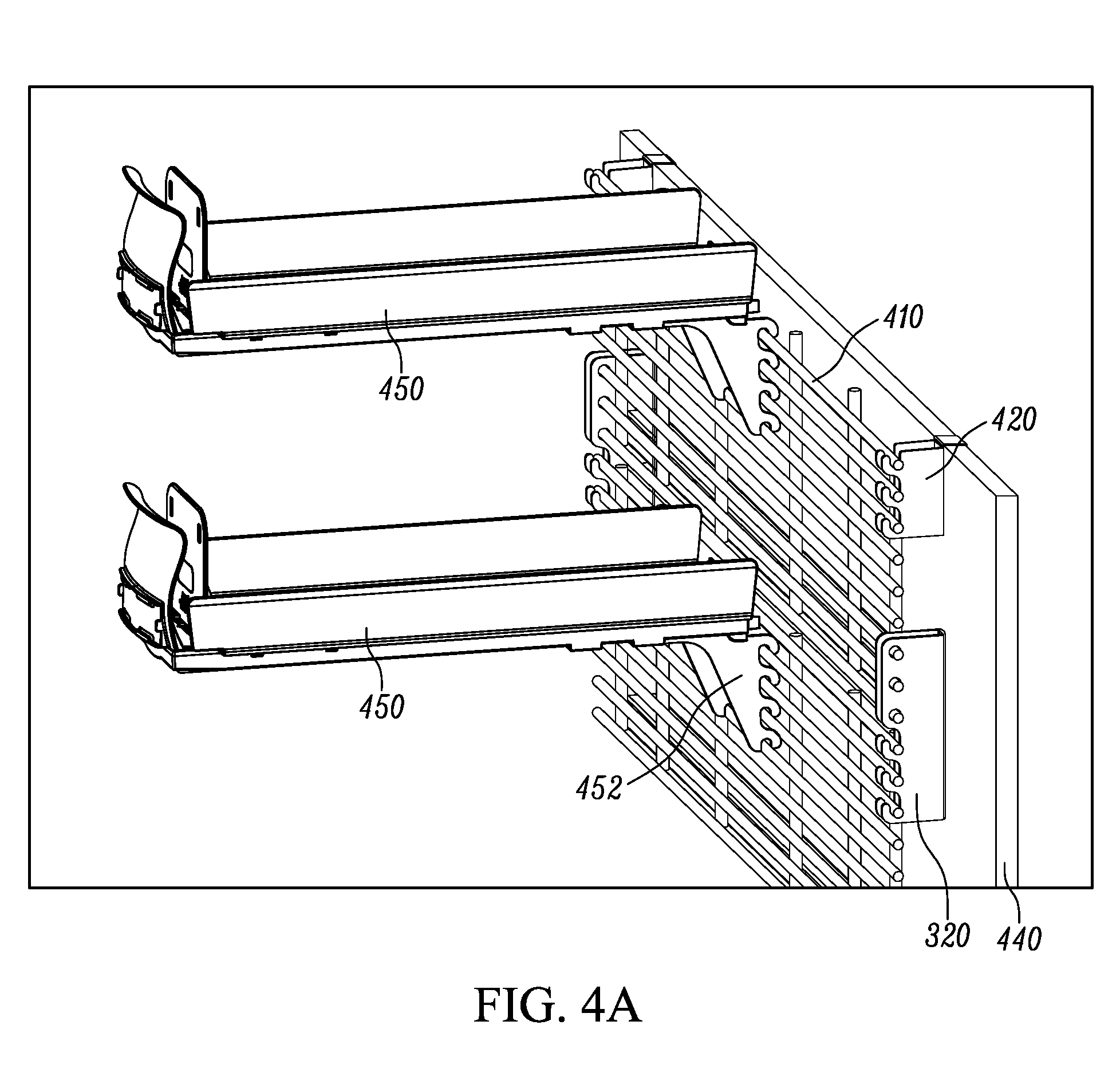
FIG. 4A is a perspective view of a product display assembly according to a third embodiment of the present invention.
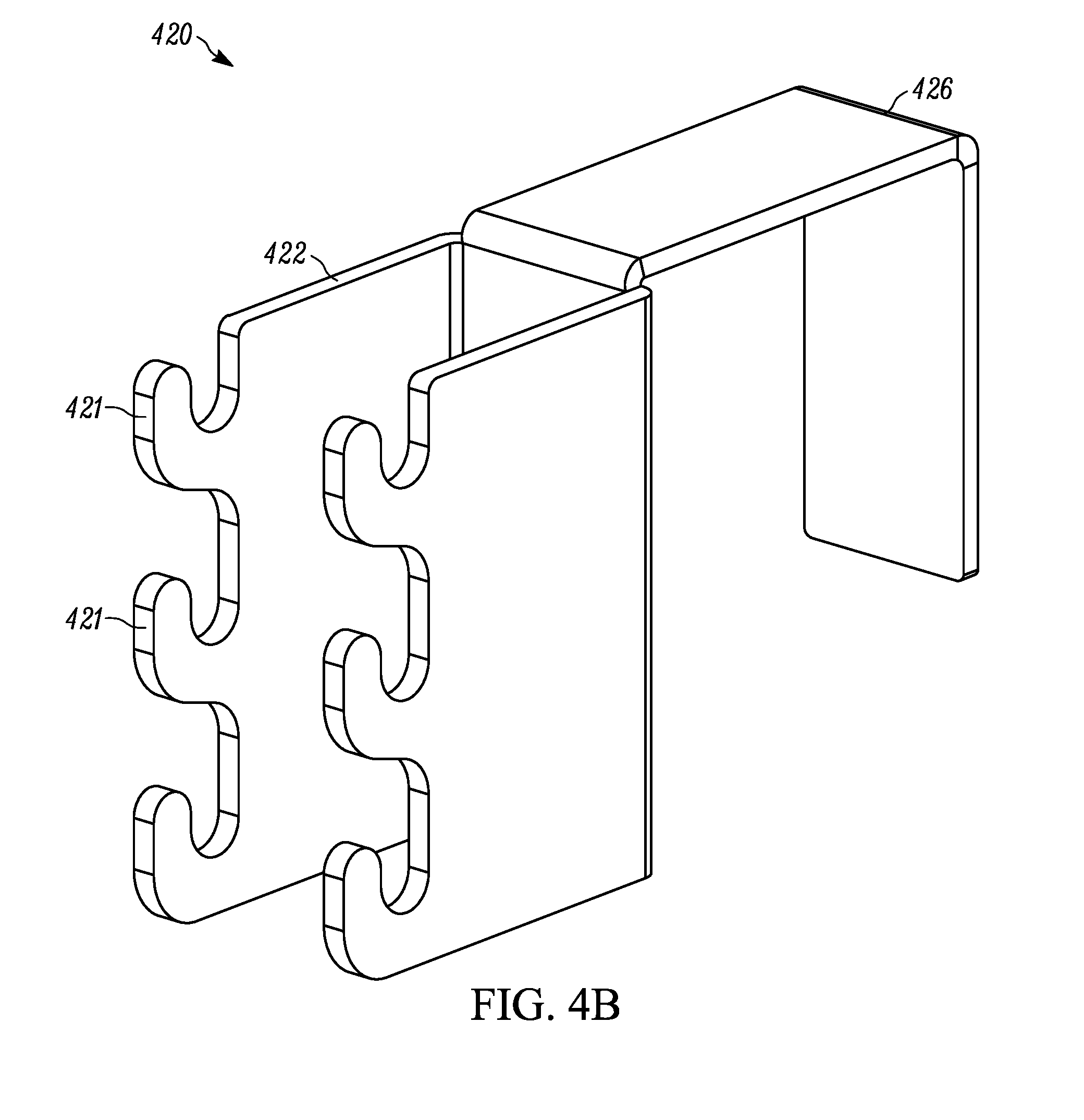
FIG. 4B is a front right perspective view of a bracket used in the assembly of FIG. 4A.
Elements in the figures are illustrated for simplicity and clarity and have not necessarily been drawn to scale or to include all features, options or attachments. For example, the dimensions and/or relative positioning of some of the elements in the figures may be exaggerated relative to other elements to help to improve understanding of various embodiments of the present invention. Also, common but well-understood elements that are useful or necessary in a commercially feasible embodiment are often not depicted in order to facilitate a less obstructed view of these various embodiments of the present invention. Certain actions and/or steps may be described or depicted in a particular order of occurrence while those skilled in the art will understand that such specificity with respect to sequence is not actually required. The terms and expressions used herein have the ordinary technical meaning as is accorded to such terms and expressions by persons skilled in the technical field as set forth above except where different specific meanings have otherwise been set forth herein.
DETAILED DESCRIPTION
Many variations of grid brackets are discussed herein and even further are contemplated in view of this disclosure. The brackets discussed herein are configured, and designed, to couple a grid to an upright structure, such as a shelving system, post, gondola and/or wall. The brackets generally comprise one or more first attachment structures configured to couple to the grid and one or more second attachment structures configured to couple to the upright structure.
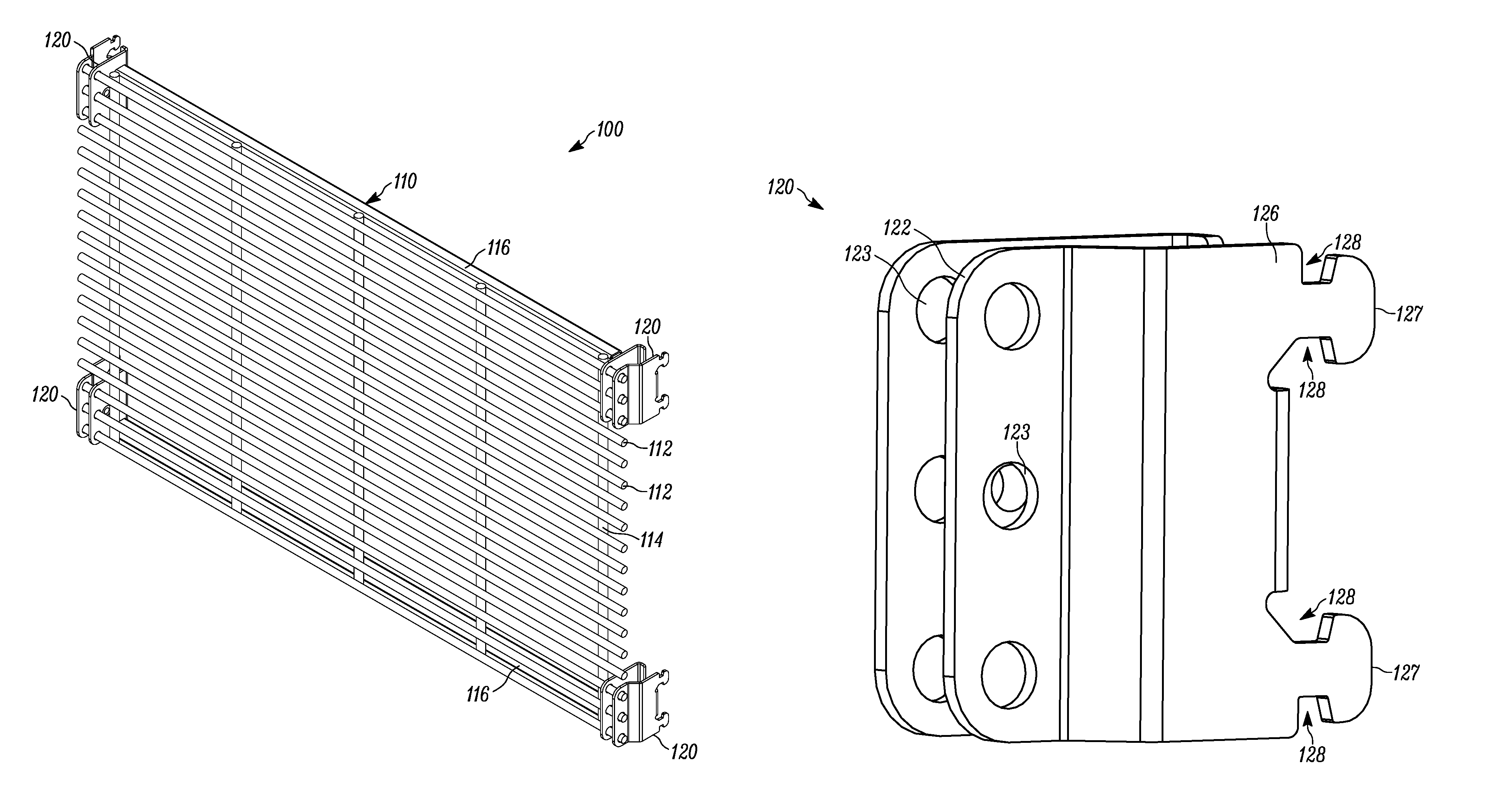
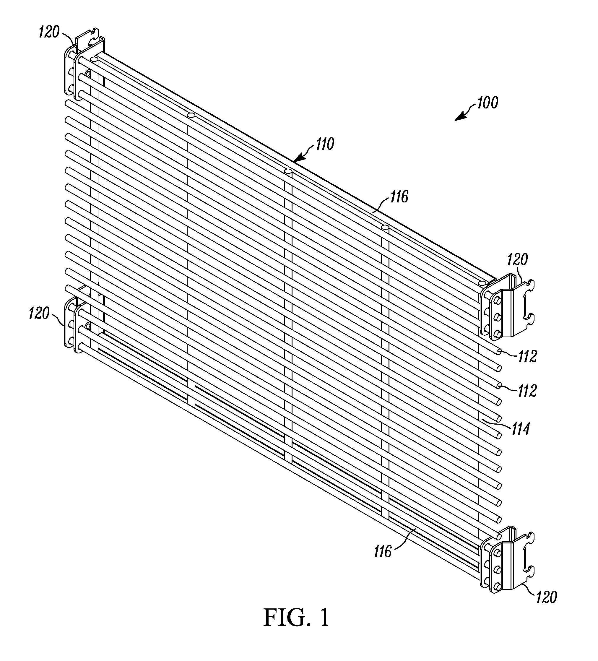
FIG. 1 illustrates a product display 100 comprising a grid 110 mounted to uprights 102a/102b by brackets 120. The grid 110 is a metal wire grid comprising a series of cross-members 112 and vertical members 114. In a preferred embodiment, the grid 110 is a standard size to fit into most displays. Example standard sizes include 4 feet by 8 feet and 2 feet by 4 feet rectangles. Other standard sizes are also considered herein, such as metric sizes. In alternative embodiments, the grid is a custom size to fit a particular display.
The cross-members 112 of the grid 110 are cylindrical metal rods. In alternative embodiments, the cross-members 112 can have different shapes such as slats, rectangular prisms, triangular prisms, or fins. These cross members 112 are used to support a variety of product displays such as hooks, baskets, hangers, shelves, and/or merchandisers. Example grids and product displays are described in U.S. Pat. No. 5,769,248, titled "PRODUCT DISPLAY GRID SYSTEM", which is incorporated herein by reference in its entirety.
In addition to the cross-members 112, the grid 110 includes one or more horizontal members 116. The horizontal members 116 add rigidity to the grid 110 to reduce twisting and/or bending of the grid 110. In one form, horizontal members 116 are placed at the top and the bottom of the grid 110. In alternative forms, additional horizontal members 116 are spaced between the top and bottom. In still further alternatives, rigidity is alternatively or additionally provided by diagonal members.
In a preferred form, the horizontal members 116 and brackets 120 are sized such that pushing the brackets 120 on either end of a horizontal member 116 up flush against the ends of the horizontal member 116 perfectly spaces the brackets 120 to fit into corresponding upright structures.
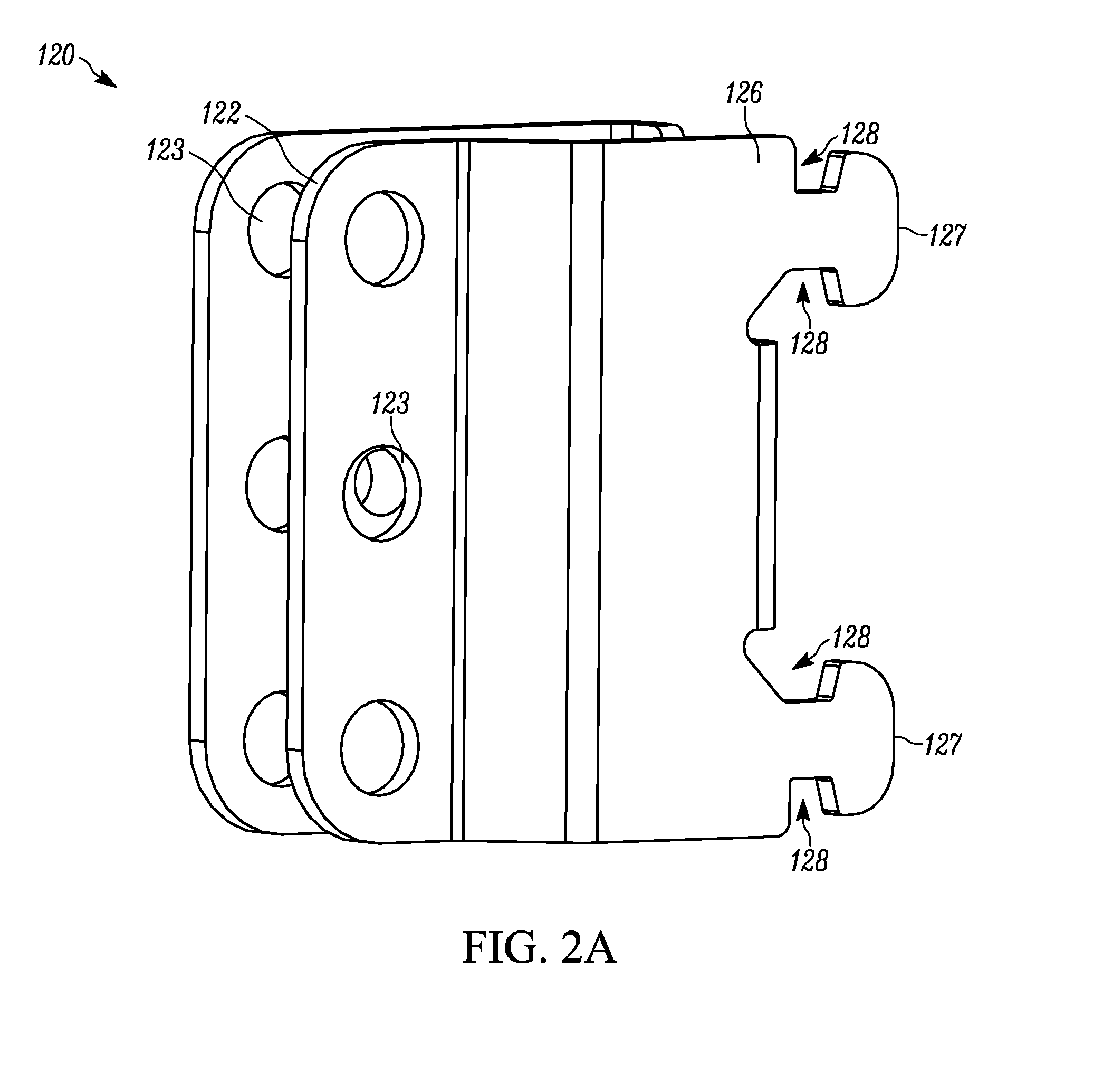
An isolated bracket 120 is shown in FIGS. 2A-2C. The bracket 120 includes a first engagement structure 122 and a second engagement structure 126. The first engagement structure 122 comprises one or more holes 123 sized to receive the cross-members of a grid. The bracket 120 is a universal bracket, meaning it is reversible so as to serve as either a left bracket or a right bracket. To this end, the bracket is symmetrical about a horizontal centerline so that it can be flipped about said centerline to change from a right side configuration to a left side configuration or vice versa.
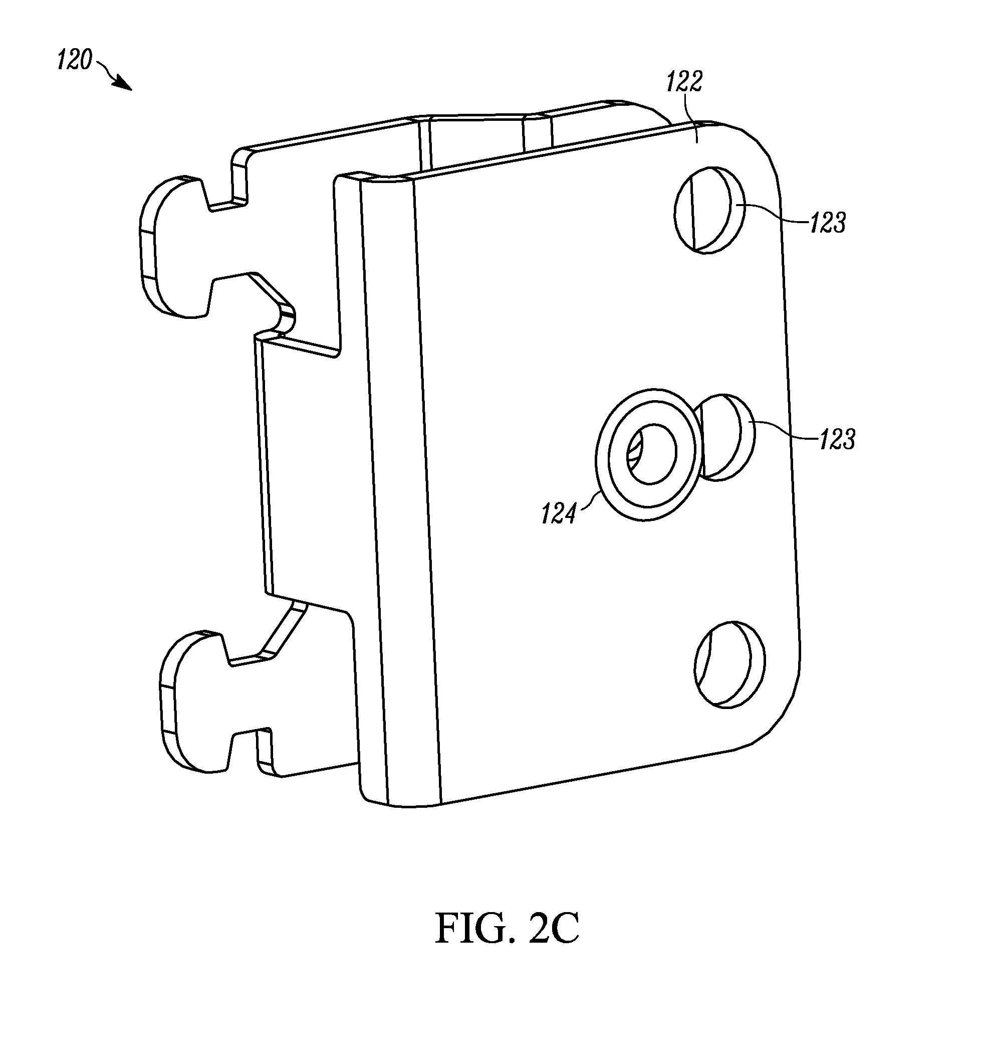
As best shown in FIGS. 2B-2C, the bracket 120 includes a securing structure 124 configured to aid in securing the bracket 120 in place on the grid. In some forms, the securing structure 124 is a frictional device configured to increase friction between the bracket 120 and the grid. In the embodiment shown, the frictional device is a rubber grommet. The grommet is configured to be deformed when the bracket 120 is placed on a grid. This deformation increases the pressure with which the securing structure 124 presses against a cross-member of the grid, thus increasing the friction therebetween. In some forms, a plurality of securing structures are used.
In alternative forms, a force other than friction can be used to secure the bracket 120 in place on the grid. For example, one or more magnets, set screws, or a gear rack and ratchet combination can be used. In one form, the bracket 120 includes one or more magnets positioned to hold the bracket against the horizontal member of the grid so as to be properly spaced as described above.
The second engagement structure 126 is configured to detachably couple the bracket 120 to an upright structure, such as a shelving system, post, gondola and/or wall. In one common form, a shelving system or gondola comprises uprights having vertically oriented slots. The second engagement structure 126 includes one or more protrusions 127 sized to fit into the standard sized slots, and/or sized to fit into the specific size slots of a corresponding upright structure. Each protrusion 127 includes a recess 128 on each end spaced forward from the back, or distal portion, of the protrusion 127. The recesses 128 receive a portion of the upright structure at the bottom of the slot such that the rest of the protrusion 127 hooks over said bottom portion to prevent the bracket 120 from pulling out. The recesses 128 are on both ends of the protrusion 127 so that the bracket 120 can be flipped about a horizontal centerline and still function as described above. This reversibility makes the bracket 120 a universal bracket. In alternative embodiments, the recesses 128 fit over cross pieces or protrusions within the slots in addition to or instead of the bottom of the slot.
The second engagement structure 126 is located on one side of the bracket 120 instead of centered. This enables two brackets 120 to be placed close together, one with the second engagement structure 126 on the right and the other with the second engagement structure 126 on the left, so that their respective second engagement structures 126 can be inserted into the same slot in an upright structure, as shown in FIG. 3A. Thus, the brackets 120 can be used in between adjacent grids.
In alternative embodiments, the second engagement structure 126 is changed to correspond to different types of upright structures. Some examples of other engagement structures include the flat back design shown in FIGS. 3B-3D and the hook design shown in FIGS. 4A-4B. Both of these are described in greater detail below.
In operation, at least two brackets 120 are placed on a grid, one on the left and one on the right. In a preferred embodiment, four brackets 120 are used with one at each corner. The brackets 120 are pressed up against the horizontal members of the grid in order to properly space them, and the securing member 124 holds the brackets 120 in this properly spaced position. The grid is then lifted and attached to upright structures by inserting the protrusions 127 into corresponding slots.
FIG. 3A illustrates a product display 300 comprising a variety of brackets according to various embodiments of the present invention. The product display 300 includes a plurality of grids 310a-310c mounted to an upright 340 by brackets 120/320. The top most grid 310a is partially supported by a bracket 120 as described above. The second engagement structure 126 is inserted into the slot 342 of the upright 340.
The bottom of the top grid 310a and the remaining grids 310b/c are mounted to the upright by a second embodiment of a universal mounting bracket 320. A bracket 320 is shown in isolation in FIGS. 3B-3C. The bracket 320 includes a first engagement structure 322 to detachably couple the bracket 320 to one or more grids 310. The first engagement structure 322 includes one or more holes 123 for receiving a cross-member of a first grid 310a as well as one or more hooks 321 for receiving a cross-member of a second grid 310b. In the embodiment shown, there is no securing structure included in the bracket 320 as in the bracket 120, however alternative embodiments with one or more of the securing structures described below are considered herein. In an alternative embodiment, the holes 323 are replaced with downward facing hooks such that the bracket 320 hangs from the top grid 310a.
The bracket 320 is symmetrical about a vertical centerline. This symmetry makes the bracket 320 a universal bracket, meaning that it can be used on both the right side of the grids 310 as well as the left side. The bracket 320 further includes a flat back 326. The flat back 326 is configured to rest substantially flush against the upright 340. In some forms, the back 326 includes securing structure for attaching to the upright 340. The securing structure could be holes or slots through which the bracket 320 could be coupled by bolts, screws, nails, or posts. Alternatively or additionally, magnets, adhesive, clamps or combinations thereof could be used to couple the bracket 320 to the upright 340.
In the embodiment shown, no such securing structure is used to couple the bracket 320 to the upright 340. Instead, the bracket 320 secures the lower grid 310b to the upper grid 310a. The top most grid 310a of the column is coupled to the upright by use of a different type of bracket 120.
In operation, brackets 120 are placed on the top corners of the top grid 310a. Brackets 320 are placed on the bottom corners of the grid 310a. The brackets 320 are placed such that the bottom 3 cross members, or however many cross members correspond to the number of holes 323, are placed in the corresponding holes. In this position, the bottom half of the brackets 320 extend below the grid 310a. The grid 310a and brackets 120/320 are then lifted as an assembly and mounted by inserting the protrusions 127 of the brackets 120 into the slots 342 of a pair of uprights 340.
A second grid 310b is then prepared by placing brackets 320 at the bottom corners as was done with the top grid 310a. No brackets 120/320 are placed at the top corners. The grid 310b and brackets are lifted as an assembly and mounted to the display 300 by placing the top cross members over the hooks 321 of the brackets 320 coupled to the top grid 310a. This process is then continued downward with additional grids 310c until the bottom of the column is reached. The bottom most grid 310c does not have brackets 320 coupled to its bottom corners.
An alternative display 400 is shown in FIG. 4A. As with the display 300, the display 400 utilizes brackets 320 to chain together a column of grids 410. The brackets in FIG. 4A could differ slightly than the brackets 320 above in that they could have a different number of holes or be intended to receive a different number of grid bars or rods (e.g., only having enough holes 323 for two cross members (or bars or rods) and enough hooks for two additional cross-members (bars or rods) as opposed to the three plus three cross member design above. This is because, as discusses above, the number of holes and hooks can vary. A minimum number of holes 323 for one cross member and hooks 321 for one cross member are all that are needed. Additional holes 323 and hooks 321 serve to spread out the load over more cross members, and therefore are preferable for longer columns and/or columns intended to support more weight.
The top two corners of the top grid 410 are supported by brackets 420. The brackets 420 are shown in greater detail in FIG. 4B. The brackets 420 include a first engagement structure 422 having a plurality of hooks 421 configured to receive the top cross members of the grid 410. The brackets 420 further include a second engagement structure 426 configured to fit over the top of a wall portion or partition 440 as shown in FIG. 4A.
In operation, the brackets 420 are hung over the top of the partition 440. The brackets 320 are coupled to the bottom corners of a grid 410 as in the previous embodiment. The grid 410 and brackets 320 are then lifted as a unit and mounted on the partition 440 by placing the top cross members of the grid 410 into the hooks 421 of the brackets 420. A series of additional grids 410 can then be added to the bottom of the brackets 320 to form a column in substantially the same manner as the grids 310b/c were added to the display 300 above.
In an alternative form, the brackets 420 include holes instead of hooks 421. By this change, the brackets 420 are instead coupled to the grid 410 first and then attached to the partition 440 as an assembly as in the previous embodiments.
The product display 400 further includes merchandisers 450. The merchandisers shown are front facing merchandisers having a spring biased pusher. The merchandisers 450 include attachment structures 452 which comprise hooks configured to hook over the cross members of the grid 410 to hang the merchandisers there from. Exemplary merchandisers are described in International Patent Application PCT/US16/43354, titled "MERCHANDISER AND METHODS RELATING TO SAME", filed on Jul. 21, 2016, which is incorporated by reference herein in its entirety.
Alternatively to the rigid attachment structure 452 shown, merchandisers or other product displays may include adjustable attachment structures to provide for greater vertical adjustment through which more efficient vertical pack out can be achieved. Example adjustable grid mounts are described in U.S. Provisional Application No. 62/371,579, titled "ADJUSTABLE GRID MOUNT AND RELATED METHODS", which is incorporated by reference herein in its entirety.
Elements in the above embodiments have three digit numbers. The first digit references the embodiment and the last two digits reference the element. Elements sharing the same last two digits across multiple embodiments are assumed to share the same description except where expressly distinguished.
Features of the various embodiments described above can be interchanged with each other in any combination to create other embodiments which are contemplated herein. For instance, the bracket 420 can be altered to include the securing structure 124 of bracket 120. Additionally, the description of brackets or display assemblies above enables a person of ordinary skill in the art to make and use those embodiments. Therefor various methods of making and using the above-described embodiments are considered herein, such as a method of display products, a method of assembling a product display, and/or a method of making a bracket.
This detailed description refers to specific examples in the drawings and illustrations. These examples are described in sufficient detail to enable those skilled in the art to practice the inventive subject matter. These examples also serve to illustrate how the inventive subject matter can be applied to various purposes or embodiments. Other embodiments are included within the inventive subject matter, as logical, mechanical, electrical, and other changes can be made to the example embodiments described herein. Features of various embodiments described herein, however essential to the example embodiments in which they are incorporated, do not limit the inventive subject matter as a whole, and any reference to the invention, its elements, operation, and application are not limiting as a whole, but serve only to define these example embodiments. This detailed description does not, therefore, limit embodiments of the invention, which are defined only by the appended claims. Each of the embodiments described herein are contemplated as falling within the inventive subject matter, which is set forth in the following claims.
In addition to the above, it should be understood that several brackets, display systems, and methods relating to same are disclosed herein. For example, a bracket is disclosed with a body having a first engagement structure and a second engagement structure wherein the first engagement structure is configured to connect to a first grid structure and the second engagement structure is configured to connect to an upright structure and/or a second grid structure. Like the brackets of FIGS. 1A-2C, or the bracket of FIGS. 3A-D, or the brackets of FIGS. 4A-B. In some forms, the first engagement structure is configured to detachably couple to the first grid structure, the second engagement structure is configured to detachably couple to an upright structure, and the bracket further comprises a securing structure configured to increase friction between the first engagement structure and the first grid structure. The securing structure may comprise a deformable member positioned to be deformed by the grid structure when the grid structure is disposed at least partially within the first engagement structure.
In some forms, the second engagement structure may comprise at least one of a protrusion used to couple the bracket to the upright structure, (e.g., such as an insertable hook structure). In other forms, the second engagement structure may comprise a recess or hole used to couple the bracket to the upright structure (e.g., such as a mating recess for receiving a mating protrusion extending from the upright itself, or a fastener opening for receiving a fastener, such as a bolt, screw, rivet, etc.). In still other forms, the second engagement structure may comprise a fastener used to couple the bracket to the upright structure (e.g., such as a bolt, screw, rivet, magnet, adhesive, etc.).
In some of the forms shown above, the first grid structure are horizontal rod or bar ends extending from a larger grid assembly and the first engagement structure comprises a plurality of substantially enclosed holes formed in the bracket for receiving the rod or bar ends, and the second engagement structure comprises at least one hook shaped protrusion for engaging a mating slot in the upright structure.
In some forms, the bracket may further define an opening proximate at least one of the substantially enclosed holes and having a deformable securing structure disposed therein to induce friction on at least one of the rod or bar ends disposed within the first engagement structure. In a preferred form, the deformable securing structure is a plastic or rubber grommet that is aligned to overlap with the substantially enclosed hole proximate the bracket opening containing the deformable structure. In this way, when the rod or bar end is inserted into the enclosed hole proximate the bracket opening containing the deformable structure, the deformable structure induces friction against the rod or bar end causing the bracket to be more securely connected to the rod or bar end and therefore the grid assembly itself. This makes it easier to position the brackets on the grid assembly in a desired orientation so that the grid assembly can be connected in the manner desired (e.g., connecting it to a slot in a gondola upright, connecting it to the top of an upright wall via a u-shaped bracket, etc.
In some forms, the bracket body is generally U shaped having a first body portion positioned substantially parallel to a second body portion with the first and second body portions being interconnected via an intermediate body portion, with the first engagement structure comprising a plurality of holes formed in each of the first and second body portions and each hole on the first body portion aligned with a corresponding hole on the second body portion, and the second engagement structure comprising a plurality of hook shaped protrusions extending from either one of the first and second body portions and/or from the intermediate body portion.
In other forms, the bracket may be used to interconnect grid assemblies or allow one grid assembly to be suspended by the other rather than be used to suspend the grid assemblies from an upright. In yet other forms, it may do both (e.g., interconnect the grid assemblies and connect them to the upright).
In one form, the first grid structure comprises a first set of horizontal rod or bar ends extending from a first grid assembly and the second grid structure comprises a second set of horizontal rod or bar ends extending from a second grid assembly and the first engagement structure comprises a plurality of substantially enclosed holes formed in the bracket for receiving the first set of horizontal rod or bar ends in a lateral direction only, and the second engagement structure comprises a plurality of open-faced channels formed in the bracket for receiving the second set of horizontal rod or bar ends in either the lateral direction or a direction transverse the lateral direction due to the open-faced channel arrangement of the second engagement structure so that the second grid structure can be suspended from the first grid structure via the bracket.
* * * * *
D00000
D00001
D00002
D00003
D00004
D00005
D00006
D00007
D00008
D00009
D00010
XML
uspto.report is an independent third-party trademark research tool that is not affiliated, endorsed, or sponsored by the United States Patent and Trademark Office (USPTO) or any other governmental organization. The information provided by uspto.report is based on publicly available data at the time of writing and is intended for informational purposes only.
While we strive to provide accurate and up-to-date information, we do not guarantee the accuracy, completeness, reliability, or suitability of the information displayed on this site. The use of this site is at your own risk. Any reliance you place on such information is therefore strictly at your own risk.
All official trademark data, including owner information, should be verified by visiting the official USPTO website at www.uspto.gov. This site is not intended to replace professional legal advice and should not be used as a substitute for consulting with a legal professional who is knowledgeable about trademark law.