System and method to balance servers based on server load status
Kannan , et al. Oc
U.S. patent number 10,447,775 [Application Number 15/936,709] was granted by the patent office on 2019-10-15 for system and method to balance servers based on server load status. This patent grant is currently assigned to A10 Networks, Inc.. The grantee listed for this patent is A10 NETWORKS, INC.. Invention is credited to Lee Chen, Rajkumar Jalan, Lalgudi Narayanan Kannan, Ronald Wai Lun Szeto, Feilong Xu.


| United States Patent | 10,447,775 |
| Kannan , et al. | October 15, 2019 |
System and method to balance servers based on server load status
Abstract
Provided are methods and systems for balancing servers based on a server load status. A method for balancing servers based on a server load status may commence with receiving, from a server of a plurality of servers, a service response to a service request. The service response may include a computing load of the server. The method may continue with receiving a next service request from a host. The method may further include determining, based on the computing load of the server, whether the server is available to process the next service request. The method may include selectively sending the next service request to the server based on the determination that the server is available to process the next service request.
| Inventors: | Kannan; Lalgudi Narayanan (Los Altos, CA), Szeto; Ronald Wai Lun (San Francisco, CA), Chen; Lee (Saratoga, CA), Xu; Feilong (San Jose, CA), Jalan; Rajkumar (Saratoga, CA) | ||||||||||
|---|---|---|---|---|---|---|---|---|---|---|---|
| Applicant: |
|
||||||||||
| Assignee: | A10 Networks, Inc. (San Jose,
CA) |
||||||||||
| Family ID: | 45890765 | ||||||||||
| Appl. No.: | 15/936,709 | ||||||||||
| Filed: | March 27, 2018 |
Prior Publication Data
| Document Identifier | Publication Date | |
|---|---|---|
| US 20180213031 A1 | Jul 26, 2018 | |
Related U.S. Patent Documents
| Application Number | Filing Date | Patent Number | Issue Date | ||
|---|---|---|---|---|---|
| 14956230 | Dec 1, 2015 | 9961135 | |||
| 12894142 | Dec 15, 2015 | 9215275 | |||
| Current U.S. Class: | 1/1 |
| Current CPC Class: | H04L 67/1008 (20130101); H04L 67/02 (20130101); H04L 67/1002 (20130101) |
| Current International Class: | H04L 29/08 (20060101) |
References Cited [Referenced By]
U.S. Patent Documents
| 5218602 | June 1993 | Grant et al. |
| 5774660 | June 1998 | Brendel et al. |
| 5935207 | August 1999 | Logue et al. |
| 5958053 | September 1999 | Denker |
| 5995981 | November 1999 | Wikstrom |
| 6003069 | December 1999 | Cavill |
| 6047268 | April 2000 | Bartoli et al. |
| 6131163 | October 2000 | Wiegel |
| 6219706 | April 2001 | Fan et al. |
| 6259705 | July 2001 | Takahashi et al. |
| 6321338 | November 2001 | Porras et al. |
| 6374300 | April 2002 | Masters |
| 6459682 | October 2002 | Ellesson et al. |
| 6587866 | July 2003 | Modi et al. |
| 6748414 | June 2004 | Boumas |
| 6772334 | August 2004 | Glawitsch |
| 6779017 | August 2004 | Lamberton et al. |
| 6779033 | August 2004 | Watson et al. |
| 6801949 | October 2004 | Bruck et al. |
| 6952728 | October 2005 | Alles et al. |
| 7010605 | March 2006 | Dharmarajan |
| 7013482 | March 2006 | Krumel |
| 7058718 | June 2006 | Fontes et al. |
| 7069438 | June 2006 | Balabine et al. |
| 7076555 | July 2006 | Orman et al. |
| 7143087 | November 2006 | Fairweather |
| 7167927 | January 2007 | Philbrick et al. |
| 7181524 | February 2007 | Lele |
| 7218722 | May 2007 | Turner et al. |
| 7228359 | June 2007 | Monteiro |
| 7234161 | June 2007 | Maufer et al. |
| 7236457 | June 2007 | Joe |
| 7254133 | August 2007 | Govindarajan et al. |
| 7269850 | September 2007 | Govindarajan et al. |
| 7277963 | October 2007 | Dolson et al. |
| 7301899 | November 2007 | Goldstone |
| 7308499 | December 2007 | Chavez |
| 7310686 | December 2007 | Uysal |
| 7328267 | February 2008 | Bashyam et al. |
| 7334232 | February 2008 | Jacobs et al. |
| 7337241 | February 2008 | Boucher et al. |
| 7343399 | March 2008 | Hayball et al. |
| 7349970 | March 2008 | Clement et al. |
| 7370353 | May 2008 | Yang |
| 7391725 | June 2008 | Huitema et al. |
| 7398317 | July 2008 | Chen et al. |
| 7423977 | September 2008 | Joshi |
| 7430755 | September 2008 | Hughes et al. |
| 7463648 | December 2008 | Eppstein et al. |
| 7467202 | December 2008 | Savchuk |
| 7472190 | December 2008 | Robinson |
| 7492766 | February 2009 | Cabeca et al. |
| 7506360 | March 2009 | Wilkinson et al. |
| 7509369 | March 2009 | Tormasov |
| 7512980 | March 2009 | Copeland et al. |
| 7533409 | May 2009 | Keane et al. |
| 7552323 | June 2009 | Shay |
| 7584262 | September 2009 | Wang et al. |
| 7584301 | September 2009 | Joshi |
| 7590736 | September 2009 | Hydrie et al. |
| 7613193 | November 2009 | Swami et al. |
| 7613822 | November 2009 | Joy et al. |
| 7673072 | March 2010 | Boucher et al. |
| 7675854 | March 2010 | Chen et al. |
| 7703102 | April 2010 | Eppstein et al. |
| 7707295 | April 2010 | Szeto et al. |
| 7711790 | May 2010 | Barrett et al. |
| 7739395 | June 2010 | Parlamas et al. |
| 7747748 | June 2010 | Allen |
| 7751409 | July 2010 | Carolan |
| 7765328 | July 2010 | Bryers et al. |
| 7792113 | September 2010 | Foschiano et al. |
| 7808994 | October 2010 | Vinokour et al. |
| 7826487 | November 2010 | Mukerji et al. |
| 7881215 | February 2011 | Daigle et al. |
| 7948952 | May 2011 | Hurtta et al. |
| 7965727 | June 2011 | Sakata et al. |
| 7970934 | June 2011 | Patel |
| 7979585 | July 2011 | Chen et al. |
| 7983258 | July 2011 | Ruben et al. |
| 7990847 | August 2011 | Leroy et al. |
| 7991859 | August 2011 | Miller et al. |
| 8032634 | October 2011 | Eppstein et al. |
| 8090866 | January 2012 | Bashyam et al. |
| 8099492 | January 2012 | Dahlin et al. |
| 8122116 | February 2012 | Matsunaga et al. |
| 8179809 | May 2012 | Eppstein et al. |
| 8185651 | May 2012 | Moran et al. |
| 8191106 | May 2012 | Choyi et al. |
| 8224971 | July 2012 | Miller et al. |
| 8266235 | September 2012 | Jalan et al. |
| 8296434 | October 2012 | Miller et al. |
| 8312507 | November 2012 | Chen et al. |
| 8379515 | February 2013 | Mukerji |
| 8499093 | July 2013 | Grosser et al. |
| 8539075 | September 2013 | Bali et al. |
| 8554929 | October 2013 | Szeto et al. |
| 8560693 | October 2013 | Wang et al. |
| 8584199 | November 2013 | Chen et al. |
| 8595791 | November 2013 | Chen et al. |
| RE44701 | January 2014 | Chen et al. |
| 8675488 | March 2014 | Sidebottom et al. |
| 8681610 | March 2014 | Mukerji |
| 8750164 | June 2014 | Casado et al. |
| 8782221 | July 2014 | Han |
| 8813180 | August 2014 | Chen et al. |
| 8826372 | September 2014 | Chen et al. |
| 8879427 | November 2014 | Krumel |
| 8885463 | November 2014 | Medved et al. |
| 8897154 | November 2014 | Jalan et al. |
| 8965957 | February 2015 | Barros |
| 8977749 | March 2015 | Han |
| 8990262 | March 2015 | Chen et al. |
| 9094364 | July 2015 | Jalan et al. |
| 9106561 | August 2015 | Jalan et al. |
| 9154577 | October 2015 | Jalan et al. |
| 9154584 | October 2015 | Han |
| 9215275 | December 2015 | Kannan et al. |
| 9219751 | December 2015 | Chen et al. |
| 9253152 | February 2016 | Chen et al. |
| 9270705 | February 2016 | Chen et al. |
| 9270774 | February 2016 | Jalan et al. |
| 9338225 | May 2016 | Jalan et al. |
| 9350744 | May 2016 | Chen et al. |
| 9356910 | May 2016 | Chen et al. |
| 9386088 | July 2016 | Zheng et al. |
| 9497201 | November 2016 | Chen et al. |
| 9531846 | December 2016 | Han et al. |
| 9544364 | January 2017 | Jalan et al. |
| 9602442 | March 2017 | Han |
| 9609052 | March 2017 | Jalan et al. |
| 9705800 | July 2017 | Sankar et al. |
| 9843484 | December 2017 | Sankar et al. |
| 9900252 | February 2018 | Chiong |
| 9906422 | February 2018 | Jalan et al. |
| 9906591 | February 2018 | Jalan et al. |
| 9942152 | April 2018 | Jalan et al. |
| 9942162 | April 2018 | Golshan et al. |
| 9960967 | May 2018 | Chen et al. |
| 9961135 | May 2018 | Kannan et al. |
| 9979801 | May 2018 | Jalan et al. |
| 2001/0049741 | December 2001 | Skene et al. |
| 2002/0032777 | March 2002 | Kawata et al. |
| 2002/0078164 | June 2002 | Reinschmidt |
| 2002/0091844 | July 2002 | Craft et al. |
| 2002/0103916 | August 2002 | Chen et al. |
| 2002/0133491 | September 2002 | Sim et al. |
| 2002/0138618 | September 2002 | Szabo |
| 2002/0143991 | October 2002 | Chow et al. |
| 2002/0178259 | November 2002 | Doyle et al. |
| 2002/0191575 | December 2002 | Kalavade et al. |
| 2002/0194335 | December 2002 | Maynard |
| 2002/0194350 | December 2002 | Lu et al. |
| 2003/0009591 | January 2003 | Hayball et al. |
| 2003/0014544 | January 2003 | Pettey |
| 2003/0023711 | January 2003 | Parmar et al. |
| 2003/0023873 | January 2003 | Ben-Itzhak |
| 2003/0035409 | February 2003 | Wang et al. |
| 2003/0035420 | February 2003 | Niu |
| 2003/0065762 | April 2003 | Stolorz et al. |
| 2003/0091028 | May 2003 | Chang et al. |
| 2003/0131245 | July 2003 | Linderman |
| 2003/0135625 | July 2003 | Fontes et al. |
| 2003/0195962 | October 2003 | Kikuchi et al. |
| 2004/0062246 | April 2004 | Boucher et al. |
| 2004/0073703 | April 2004 | Boucher et al. |
| 2004/0078419 | April 2004 | Ferrari et al. |
| 2004/0078480 | April 2004 | Boucher et al. |
| 2004/0111516 | June 2004 | Cain |
| 2004/0128312 | July 2004 | Shalabi et al. |
| 2004/0139057 | July 2004 | Hirata et al. |
| 2004/0139108 | July 2004 | Tang et al. |
| 2004/0141005 | July 2004 | Banatwala et al. |
| 2004/0143599 | July 2004 | Shalabi et al. |
| 2004/0187032 | September 2004 | Gels et al. |
| 2004/0199616 | October 2004 | Karhu |
| 2004/0199646 | October 2004 | Susai et al. |
| 2004/0202182 | October 2004 | Lund et al. |
| 2004/0210623 | October 2004 | Hydrie et al. |
| 2004/0210663 | October 2004 | Phillips et al. |
| 2004/0213158 | October 2004 | Collett et al. |
| 2004/0268358 | December 2004 | Darling et al. |
| 2005/0005207 | January 2005 | Herneque |
| 2005/0009520 | January 2005 | Herrero et al. |
| 2005/0021848 | January 2005 | Jorgenson |
| 2005/0027862 | February 2005 | Nguyen et al. |
| 2005/0036501 | February 2005 | Chung et al. |
| 2005/0036511 | February 2005 | Baratakke et al. |
| 2005/0044270 | February 2005 | Grove et al. |
| 2005/0074013 | April 2005 | Hershey et al. |
| 2005/0080890 | April 2005 | Yang et al. |
| 2005/0102400 | May 2005 | Nakahara et al. |
| 2005/0125276 | June 2005 | Rusu |
| 2005/0163073 | July 2005 | Heller et al. |
| 2005/0198335 | September 2005 | Brown et al. |
| 2005/0213586 | September 2005 | Cyganski et al. |
| 2005/0240989 | October 2005 | Kim et al. |
| 2005/0249225 | November 2005 | Singhal |
| 2005/0259586 | November 2005 | Hafid et al. |
| 2005/0289231 | December 2005 | Harada et al. |
| 2006/0023721 | February 2006 | Miyake et al. |
| 2006/0036610 | February 2006 | Wang |
| 2006/0036733 | February 2006 | Fujimoto et al. |
| 2006/0064478 | March 2006 | Sirkin |
| 2006/0069774 | March 2006 | Chen et al. |
| 2006/0069804 | March 2006 | Miyake et al. |
| 2006/0077926 | April 2006 | Rune |
| 2006/0092950 | May 2006 | Arregoces et al. |
| 2006/0098645 | May 2006 | Walkin |
| 2006/0112170 | May 2006 | Sirkin |
| 2006/0168319 | July 2006 | Trossen |
| 2006/0187901 | August 2006 | Cortes et al. |
| 2006/0190997 | August 2006 | Mahajani et al. |
| 2006/0209789 | September 2006 | Gupta et al. |
| 2006/0230129 | October 2006 | Swami et al. |
| 2006/0233100 | October 2006 | Luft et al. |
| 2006/0251057 | November 2006 | Kwon et al. |
| 2006/0277303 | December 2006 | Hegde et al. |
| 2006/0280121 | December 2006 | Matoba |
| 2007/0019543 | January 2007 | Wei et al. |
| 2007/0086382 | April 2007 | Narayanan et al. |
| 2007/0094396 | April 2007 | Takano et al. |
| 2007/0118881 | May 2007 | Mitchell et al. |
| 2007/0127381 | June 2007 | Oh et al. |
| 2007/0156919 | July 2007 | Potti et al. |
| 2007/0165622 | July 2007 | O'Rourke et al. |
| 2007/0185998 | August 2007 | Touitou et al. |
| 2007/0203890 | August 2007 | Sareen et al. |
| 2007/0230337 | October 2007 | Igarashi et al. |
| 2007/0245090 | October 2007 | King et al. |
| 2007/0259673 | November 2007 | Willars et al. |
| 2007/0283429 | December 2007 | Chen et al. |
| 2007/0286077 | December 2007 | Wu |
| 2007/0288247 | December 2007 | Mackay |
| 2007/0294209 | December 2007 | Strub et al. |
| 2008/0031263 | February 2008 | Ervin et al. |
| 2008/0101396 | May 2008 | Miyata |
| 2008/0109452 | May 2008 | Patterson |
| 2008/0109870 | May 2008 | Sherlock et al. |
| 2008/0134332 | June 2008 | Keohane et al. |
| 2008/0162679 | July 2008 | Maher et al. |
| 2008/0228781 | September 2008 | Chen et al. |
| 2008/0250099 | October 2008 | Shen et al. |
| 2008/0263209 | October 2008 | Pisharody et al. |
| 2008/0271130 | October 2008 | Ramamoorthy |
| 2008/0282254 | November 2008 | Blander et al. |
| 2008/0291911 | November 2008 | Lee et al. |
| 2009/0049198 | February 2009 | Blinn et al. |
| 2009/0070470 | March 2009 | Bauman et al. |
| 2009/0077651 | March 2009 | Poeluev |
| 2009/0092124 | April 2009 | Singhal et al. |
| 2009/0106830 | April 2009 | Maher |
| 2009/0138606 | May 2009 | Moran et al. |
| 2009/0138945 | May 2009 | Savchuk |
| 2009/0141634 | June 2009 | Rothstein et al. |
| 2009/0164614 | June 2009 | Christian et al. |
| 2009/0172093 | July 2009 | Matsubara |
| 2009/0213858 | August 2009 | Dolganow et al. |
| 2009/0222583 | September 2009 | Josefsberg et al. |
| 2009/0227228 | September 2009 | Hu et al. |
| 2009/0228547 | September 2009 | Miyaoka et al. |
| 2009/0262741 | October 2009 | Jungck et al. |
| 2009/0271472 | October 2009 | Scheifler et al. |
| 2009/0313379 | December 2009 | Rydnell et al. |
| 2010/0008229 | January 2010 | Bi et al. |
| 2010/0023621 | January 2010 | Ezolt et al. |
| 2010/0036952 | February 2010 | Hazlewood et al. |
| 2010/0054139 | March 2010 | Chun et al. |
| 2010/0061319 | March 2010 | Aso et al. |
| 2010/0064008 | March 2010 | Yan et al. |
| 2010/0082787 | April 2010 | Kommula et al. |
| 2010/0083076 | April 2010 | Ushiyama |
| 2010/0094985 | April 2010 | Abu-Samaha et al. |
| 2010/0098417 | April 2010 | Tse-Au |
| 2010/0106833 | April 2010 | Banerjee et al. |
| 2010/0106854 | April 2010 | Kim et al. |
| 2010/0128606 | May 2010 | Patel et al. |
| 2010/0162378 | June 2010 | Jayawardena et al. |
| 2010/0205310 | August 2010 | Altshuler et al. |
| 2010/0210265 | August 2010 | Borzsei et al. |
| 2010/0217793 | August 2010 | Preiss |
| 2010/0223630 | September 2010 | Degenkolb et al. |
| 2010/0228819 | September 2010 | Wei |
| 2010/0228878 | September 2010 | Xu et al. |
| 2010/0235507 | September 2010 | Szeto et al. |
| 2010/0235522 | September 2010 | Chen et al. |
| 2010/0238828 | September 2010 | Russell |
| 2010/0265824 | October 2010 | Chao et al. |
| 2010/0268814 | October 2010 | Cross et al. |
| 2010/0293296 | November 2010 | Hsu et al. |
| 2010/0312740 | December 2010 | Clemm et al. |
| 2010/0318631 | December 2010 | Shukla |
| 2010/0322252 | December 2010 | Suganthi et al. |
| 2010/0330971 | December 2010 | Selitser et al. |
| 2010/0333101 | December 2010 | Pope et al. |
| 2011/0007652 | January 2011 | Bai |
| 2011/0019550 | January 2011 | Bryers et al. |
| 2011/0023071 | January 2011 | Li et al. |
| 2011/0029599 | February 2011 | Pulleyn et al. |
| 2011/0032941 | February 2011 | Quach et al. |
| 2011/0040826 | February 2011 | Chadzelek et al. |
| 2011/0047294 | February 2011 | Singh et al. |
| 2011/0060831 | March 2011 | Ishii et al. |
| 2011/0060840 | March 2011 | Susai et al. |
| 2011/0099403 | April 2011 | Miyata et al. |
| 2011/0110294 | May 2011 | Valluri et al. |
| 2011/0145324 | June 2011 | Reinart et al. |
| 2011/0153834 | June 2011 | Bharrat |
| 2011/0178985 | July 2011 | San Martin Arribas et al. |
| 2011/0185073 | July 2011 | Jagadeeswaran et al. |
| 2011/0191773 | August 2011 | Pavel et al. |
| 2011/0196971 | August 2011 | Reguraman et al. |
| 2011/0276695 | November 2011 | Maldaner |
| 2011/0276982 | November 2011 | Nakayama et al. |
| 2011/0289496 | November 2011 | Steer |
| 2011/0292939 | December 2011 | Subramaian et al. |
| 2011/0302256 | December 2011 | Sureshehandra et al. |
| 2011/0307541 | December 2011 | Walsh et al. |
| 2012/0008495 | January 2012 | Shen et al. |
| 2012/0023231 | January 2012 | Ueno |
| 2012/0026897 | February 2012 | Guichard et al. |
| 2012/0030341 | February 2012 | Jensen et al. |
| 2012/0066371 | March 2012 | Patel et al. |
| 2012/0084460 | April 2012 | McGinnity et al. |
| 2012/0106355 | May 2012 | Ludwig |
| 2012/0117571 | May 2012 | Davis et al. |
| 2012/0144014 | June 2012 | Natham et al. |
| 2012/0151353 | June 2012 | Joanny |
| 2012/0170548 | July 2012 | Rajagopalan et al. |
| 2012/0173759 | July 2012 | Agarwal et al. |
| 2012/0191839 | July 2012 | Maynard |
| 2012/0239792 | September 2012 | Banerjee et al. |
| 2012/0240185 | September 2012 | Kapoor et al. |
| 2012/0290727 | November 2012 | Tivig |
| 2012/0297046 | November 2012 | Raja et al. |
| 2013/0046876 | February 2013 | Narayana et al. |
| 2013/0058335 | March 2013 | Koponen et al. |
| 2013/0074177 | March 2013 | Varadhan et al. |
| 2013/0083725 | April 2013 | Mallya et al. |
| 2013/0124713 | May 2013 | Feinberg et al. |
| 2013/0148500 | June 2013 | Sonoda et al. |
| 2013/0173795 | July 2013 | McPherson |
| 2013/0176854 | July 2013 | Chisu et al. |
| 2013/0191486 | July 2013 | Someya et al. |
| 2013/0198385 | August 2013 | Han et al. |
| 2013/0250765 | September 2013 | Ehsan et al. |
| 2013/0250770 | September 2013 | Zou et al. |
| 2013/0258846 | October 2013 | Damola |
| 2013/0268646 | October 2013 | Doron et al. |
| 2013/0282791 | October 2013 | Kruglick |
| 2013/0336159 | December 2013 | Previdi et al. |
| 2014/0226658 | August 2014 | Kakadia et al. |
| 2014/0235249 | August 2014 | Jeong et al. |
| 2014/0248914 | September 2014 | Aoyagi et al. |
| 2014/0258465 | September 2014 | Li |
| 2014/0269728 | September 2014 | Jalan et al. |
| 2014/0286313 | September 2014 | Fu et al. |
| 2014/0298091 | October 2014 | Carlen et al. |
| 2014/0325649 | October 2014 | Zhang |
| 2014/0330982 | November 2014 | Jalan et al. |
| 2014/0334485 | November 2014 | Jain et al. |
| 2014/0359052 | December 2014 | Joachimpillai et al. |
| 2015/0098333 | April 2015 | Lin et al. |
| 2015/0156223 | June 2015 | Xu et al. |
| 2015/0215436 | July 2015 | Kancherla |
| 2015/0237173 | August 2015 | Virkki et al. |
| 2015/0312268 | October 2015 | Ray |
| 2015/0350048 | December 2015 | Sampat et al. |
| 2015/0350379 | December 2015 | Jalan et al. |
| 2016/0042014 | February 2016 | Jalan et al. |
| 2016/0044095 | February 2016 | Sankar et al. |
| 2016/0094470 | March 2016 | Skog |
| 2016/0139910 | May 2016 | Ramanathan et al. |
| 2016/0164792 | June 2016 | Oran |
| 1372662 | Oct 2002 | CN | |||
| 1449618 | Oct 2003 | CN | |||
| 1473300 | Feb 2004 | CN | |||
| 1529460 | Sep 2004 | CN | |||
| 1575582 | Feb 2005 | CN | |||
| 1714545 | Dec 2005 | CN | |||
| 1725702 | Jan 2006 | CN | |||
| 1910869 | Feb 2007 | CN | |||
| 101004740 | Jul 2007 | CN | |||
| 101094225 | Dec 2007 | CN | |||
| 101163336 | Apr 2008 | CN | |||
| 101169785 | Apr 2008 | CN | |||
| 101189598 | May 2008 | CN | |||
| 101193089 | Jun 2008 | CN | |||
| 101247349 | Aug 2008 | CN | |||
| 101261644 | Sep 2008 | CN | |||
| 101495993 | Jul 2009 | CN | |||
| 101878663 | Nov 2010 | CN | |||
| 102143075 | Aug 2011 | CN | |||
| 102546590 | Jul 2012 | CN | |||
| 102571742 | Jul 2012 | CN | |||
| 102577252 | Jul 2012 | CN | |||
| 102918801 | Feb 2013 | CN | |||
| 103533018 | Jan 2014 | CN | |||
| 103944954 | Jul 2014 | CN | |||
| 104040990 | Sep 2014 | CN | |||
| 104067569 | Sep 2014 | CN | |||
| 104106241 | Oct 2014 | CN | |||
| 104137491 | Nov 2014 | CN | |||
| 104796396 | Jul 2015 | CN | |||
| 102577252 | Mar 2016 | CN | |||
| 102918801 | May 2016 | CN | |||
| 102571742 | Jul 2016 | CN | |||
| 104067569 | Feb 2017 | CN | |||
| 1209876 | May 2002 | EP | |||
| 1770915 | Apr 2007 | EP | |||
| 1885096 | Feb 2008 | EP | |||
| 2296313 | Mar 2011 | EP | |||
| 2577910 | Apr 2013 | EP | |||
| 2622795 | Aug 2013 | EP | |||
| 2647174 | Oct 2013 | EP | |||
| 2760170 | Jul 2014 | EP | |||
| 27772026 | Sep 2014 | EP | |||
| 2901308 | Aug 2015 | EP | |||
| 2772026 | Feb 2017 | EP | |||
| 1182560 | Nov 2013 | HK | |||
| 1183569 | Dec 2013 | HK | |||
| 1183996 | Jan 2014 | HK | |||
| 1189438 | Jan 2014 | HK | |||
| 1198565 | May 2015 | HK | |||
| 1198848 | Jun 2015 | HK | |||
| 1199153 | Jun 2015 | HK | |||
| 1199779 | Jul 2015 | HK | |||
| 1200617 | Aug 2015 | HK | |||
| 3764CHN2014 | Sep 2015 | IN | |||
| 261CHE2014 | Jan 2016 | IN | |||
| 1668CHENP2015 | Jul 2016 | IN | |||
| H0997233 | Apr 1997 | JP | |||
| H1196128 | Apr 1999 | JP | |||
| H11338836 | Dec 1999 | JP | |||
| 2000276432 | Oct 2000 | JP | |||
| 2000307634 | Nov 2000 | JP | |||
| 2001051859 | Feb 2001 | JP | |||
| 2001298449 | Oct 2001 | JP | |||
| 2002091936 | Mar 2002 | JP | |||
| 2003141068 | May 2003 | JP | |||
| 2003186776 | Jul 2003 | JP | |||
| 2005141441 | Jun 2005 | JP | |||
| 2006332825 | Dec 2006 | JP | |||
| 2008040718 | Feb 2008 | JP | |||
| 2009500731 | Jan 2009 | JP | |||
| 2013528330 | Jul 2013 | JP | |||
| 2014504484 | Feb 2014 | JP | |||
| 2014143686 | Aug 2014 | JP | |||
| 2015507380 | Mar 2015 | JP | |||
| 5855663 | Feb 2016 | JP | |||
| 5906263 | Apr 2016 | JP | |||
| 5913609 | Apr 2016 | JP | |||
| 5946189 | Jul 2016 | JP | |||
| 5963766 | Aug 2016 | JP | |||
| 20080008340 | Jan 2008 | KR | |||
| 100830413 | May 2008 | KR | |||
| 20130096624 | Aug 2013 | KR | |||
| 101576585 | Dec 2015 | KR | |||
| 101632187 | Jun 2016 | KR | |||
| 101692751 | Jan 2017 | KR | |||
| WO2001013228 | Feb 2001 | WO | |||
| WO2001014990 | Mar 2001 | WO | |||
| WO2003103237 | Dec 2003 | WO | |||
| WO2004084085 | Sep 2004 | WO | |||
| WO2006098033 | Sep 2006 | WO | |||
| WO2008053954 | May 2008 | WO | |||
| WO2008078593 | Jul 2008 | WO | |||
| WO2011049770 | Apr 2011 | WO | |||
| WO2011079381 | Jul 2011 | WO | |||
| WO2011149796 | Dec 2011 | WO | |||
| WO2012050747 | Apr 2012 | WO | |||
| WO2012075237 | Jun 2012 | WO | |||
| WO2012083264 | Jun 2012 | WO | |||
| WO2012097015 | Jul 2012 | WO | |||
| WO2013070391 | May 2013 | WO | |||
| WO2013081952 | Jun 2013 | WO | |||
| WO2013096019 | Jun 2013 | WO | |||
| WO2013112492 | Aug 2013 | WO | |||
| WO2013189024 | Dec 2013 | WO | |||
| WO2014031046 | Feb 2014 | WO | |||
| WO2014052099 | Apr 2014 | WO | |||
| WO2014088741 | Jun 2014 | WO | |||
| WO2014093829 | Jun 2014 | WO | |||
| WO2014138483 | Sep 2014 | WO | |||
| WO2014144837 | Sep 2014 | WO | |||
| WO2014179753 | Nov 2014 | WO | |||
| WO2015153020 | Oct 2015 | WO | |||
Other References
|
Abe, et al., "Adaptive Split Connection Schemes in Advanced Relay Nodes," IEICE Technical Report, 2010, vol. 109 (438), pp. 25-30. cited by applicant . Cardellini, et al., "Dynamic Load Balancing on Web-Server Systems," IEEE Internet Computing, 1999, vol. 3 (3), pp. 28-39. cited by applicant . FreeBSD, "tcp--TCP Protocal," Linux Programme.quadrature. s Manual [online], 2007, [retrieved on Apr. 13, 2016], Retreived from the Internet: <https://www.freebsd.org/cgi/man.cgi?query=tcp&apropos=0&sek- tion=7&manpath=SuSe+Linux%2Fi386+11.0&format=asci>. cited by applicant . Gite, "Linux Tune Network Stack (Buffers Size) to Increase Networking Performance," nixCraft [online], 2009, [retreived on Apr. 13, 2016], Retreived from the Internet: <URL:http://www.cyberciti.biz/faq/linux-tcp-tuning/>. cited by applicant . Goldszmidt, et al., "NetDispatcher: A TCP Connection Router," IBM Researc Report, RC 20853, 1997, pp. 1-31. cited by applicant . Kjaer, et al., "Resource Allocation and Disturbance Rejection in Web Servers Using SLAs and Virtualized Servers," IEEE Transactions on Network Service Management, 2009, vol. 6 (4), pp. 226-239. cited by applicant . Koike, et al., "Transport Middleware for Network-Based Control," IEICE Technical Report, 2000, vol. 100 (53), pp. 13-18. cited by applicant . Sharifian, et al., "An Approximation-Based Load-Balancing Algorithm with Admission Control for Cluster Web Servers with Dynamic Workloads," The Journal of Supercomputing, 2010, vol. 53 (3), pp. 440-463. cited by applicant . Spatscheck, et al., "Optimizing TCP Forwarder Performance," IEEE/ACM Transactions on Networking, 2000, vol. 8(2), pp. 146-157. cited by applicant . Search Report and Written Opinion dated Apr. 10, 2012 for PCT Application No. PCT/US2011/052225. cited by applicant . Yamamoto, et al., "Performance Evaluation of Window Size in Proxy-Based TCP for Multi-Hop Wireless Networks," IPSJ SIG Technical Reports, 2008, vol. 2008 (44), pp. 109-114. cited by applicant. |
Primary Examiner: Christensen; Scott B
Attorney, Agent or Firm: Kline; Keith The Kline Law Firm PC
Parent Case Text
CROSS-REFERENCE TO RELATED APPLICATIONS
This application is a continuation of U.S. patent application Ser. No. 14/956,230, filed Dec. 1, 2015, entitled "System and Method to Balance Servers Based on Server Load Status", which is a continuation and claims the benefit of U.S. patent application Ser. No. 12/894,142, filed Sep. 30, 2010 and entitled "System and Method to Balance Servers Based on Server Load Status", now U.S. Pat. No. 9,215,275, issued Dec. 15, 2015. The disclosures of the above-referenced applications are incorporated herein by reference in their entirety for all purposes.
Claims
What is claimed is:
1. A system for balancing servers based on a server load status, the system comprising: a plurality of servers configured to process service requests; and a service gateway comprising a processor and a computer readable storage medium having a computer readable program code embodied therewith, wherein the computer readable program code when executed by the processor causes the service gateway to: receive, from a server of the plurality of servers, a service response to a service request, the service request including a Uniform Resource Locator (URL) of a plurality of URLs, the service response comprising a computing load of the server, each server of the plurality of servers being configured to act as a primary server for the URL, wherein the service gateway is pre-configured to: automatically select, for each URL of the plurality of URLs, the primary server to process service requests associated with the each URL, and select a secondary server to process the service requests associated with each URL for when the primary server is unavailable to process the service requests; receive a next service request from a host, the next service request including the URL; based on the URL and the computing load of the server, determine whether the server can currently act as the primary server for processing the next service request; and based on the determination, selectively send the next service request to the server.
2. The system of claim 1, wherein the service gateway is further configured to: receive the service request from the host, the service request including a first Uniform Resource Locator (URL) of a plurality of URLs, the first URL being associated with at least one server of the plurality of servers; determine that the server is the primary server configured to process the first URL and a further server is the secondary server configured to process the first URL; based on the determination that the server is the primary server, select the server to process the service request; and send the service request to the server.
3. The system of claim 2, wherein each of the plurality of URLs is individually resolved to the primary server configured to process the URL and the secondary server configured to process the URL, each server of the plurality of servers being configured as one of primary servers and one of secondary servers for different URLs.
4. The system of claim 3, wherein the computing load of the server includes a server status of the server.
5. The system of claim 4, wherein the server status indicates one or more of the following: the server is not busy when the server is available for serving as the primary server and is available for serving as the secondary server, the server is busy when the server is available for serving as the primary server and is unavailable for serving as the secondary server, and the server is very busy when the server is available for serving as the primary server with restrictions and is unavailable for serving as the secondary server.
6. The system of claim 4, wherein the determining by the service gateway whether the server is available to process the next service request comprises: determining that the server status indicates the server is not busy; determining that the next service request includes a second URL associated with the server as the primary server to process the second URL; and in response to determination that the server is not busy and the next service request includes the second URL associated with the server as the primary server, selecting the server to process the next service request.
7. The system of claim 4, wherein the determination by the service gateway whether the server is available to process the next service request comprises: determining that the server status indicates the server is busy; determining that the next service request includes a second URL associated with the server as the primary server to process the second URL; and in response to determination that the server is busy and the next service request includes the second URL associated with the server as the primary server, selecting the server to process the next service request.
8. The system of claim 4, wherein the determination by the service gateway whether the server is available to process the next service request comprises: determining that the server status indicates the server is busy; determining that the next service request includes a second URL associated with the server as the secondary server to process the second URL; and in response to determination that the server is busy and the next service request includes the second URL associated with the server as the secondary server, selecting a different server to process the next service request.
9. The system of claim 4, wherein the determining by the service gateway whether the server is available to process the next service request comprises: determining that the server status indicates the server is very busy; determining that the next service request includes a second URL associated with the server as the primary server to process the second URL; and in response to determination that the server is very busy and the next service request includes the second URL associated with the server as the primary server, configuring a timer for a duration; and in response to an expiration of the timer, selecting the server to process the next service request.
10. The system of claim 1, wherein the service response is one of the following: a Hypertext Transport Protocol response, an Extensible Markup Language document, a Session Initiation Protocol packet, and a File Transfer Protocol response.
11. A method for balancing servers based on a server load status, the method comprising: receiving, by a service gateway, from a server of a plurality of servers, a service response to a service request, the service request including a Uniform Resource Locator (URL) of a plurality of URLs, the service response comprising a computing load of the server, each server of the plurality of servers being configured to act as a primary server for the URL, wherein the service gateway: automatically selects, for each URL of the plurality of URLs, the primary server to process service requests associated with the each URL, and selects a secondary server to process the service requests associated with each URL for when the primary server is unavailable to process the service requests; receiving, by the service gateway, a next service request from a host, the next service request including the URL; based on the URL and the computing load of the server, determining, by the service gateway, whether the server can currently act as the primary server for processing the next service request; and based on the determination, selectively sending, by the service gateway, the next service request to the server.
12. The method of claim 11, further comprising: receiving, by the service gateway, the service request from the host, the service request including a first Uniform Resource Locator (URL) of a plurality of URLs, the first URL being associated with at least one server of the plurality of servers; determining that the server is the primary server configured to process the first URL and a further server is the secondary server configured to process the first URL; based on the determination that the server is the primary server, selecting the server to process the service request; and sending the service request to the server.
13. The method of claim 12, wherein each of the plurality of URLs is individually resolved to the primary server configured to process the URL and the secondary server is configured to process the URL, each server of the plurality of servers being configured as one of primary servers and one of secondary servers for different URLs.
14. The method of claim 13, wherein the computing load of the server includes a server status of the server.
15. The method of claim 14, wherein the server status indicates one or more of the following: the server is not busy when the server is available for serving as the primary server and is available for serving as the secondary server, the server is busy when the server is available for serving as the primary server and is unavailable for serving as the secondary server, and the server is very busy when the server is available for serving as the primary server with restrictions and is unavailable for serving as the secondary server.
16. The method of claim 14, wherein the determining whether the server is available to process the next service request comprises: determining, by the service gateway, that the server status indicates the server is not busy; determining, by the service gateway, that the next service request includes a second URL associated with the server as the primary server to process the second URL; and in response to determination that the server is not busy and the next service request includes the second URL associated with the server as the primary server, selecting, by the service gateway, the server to process the next service request.
17. The method of claim 14, wherein the determination whether the server is available to process the next service request comprises: determining, by the service gateway, that the server status indicates the server is busy; determining, by the service gateway, that the next service request includes a second URL associated with the server as the primary server to process the second URL; and in response to determination that the server is busy and the next service request includes the second URL associated with the server as the primary server, selecting, by the service gateway, the server to process the next service request.
18. The method of claim 14, wherein the determining whether the server is available to process the next service request comprises: determining, by the service gateway, that the server status indicates the server is busy; determining, by the service gateway, that the next service request includes a second URL associated with the server as the secondary server to process the second URL; and in response to determination that the server is busy and the next service request includes the second URL associated with the server as the secondary server, selecting, by the service gateway, a different server to process the next service request.
19. The method of claim 14, wherein the determining whether the server is available to process the next service request comprises: determining, by the service gateway, that the server status indicates the server is very busy; determining, by the service gateway, that the next service request includes a second URL associated with the server as the primary server to process the second URL; and in response to determination that the server is very busy and the next service request includes the second URL associated with the server as the primary server, configuring, by the service gateway, a timer for a duration; and in response to an expiration of the timer, selecting, by the service gateway, the server to process the next service request.
20. A system for balancing servers based on a server load status, the system comprising: a plurality of servers configured to process service requests; and a service gateway comprising a processor and a computer readable storage medium having a computer readable program code embodied therewith, wherein the computer readable program code, when executed by the processor causes the service gateway to: receive a service request from the host, the service request including a first Uniform Resource Locator (URL) of a plurality of URLs, the first URL being associated with at least one server of a plurality of servers; determine that a server of the plurality of servers is a primary server configured to process the first URL and a further server of the plurality of servers is a secondary server configured to process the first URL, wherein the service gateway is pre-configured to: automatically select, for each URL of the plurality of URLs, the primary server to process service requests associated with the each URL, and select the secondary server to process the service requests associated with each URL for when the primary server is unavailable to process the service requests; based on the determination that the server is the primary server, select the server to process the service request; send the service request to the server; receive, from the server, a service response to the service request, the service request including URL, the service response comprising a computing load of the server, each server of the plurality of servers being configured to act as the primary server for the URL; receive a next service request from a host, the next service request including the URL; based on the URL and the computing load of the server, determine whether the server can currently act as the primary server for processing the next service request, wherein the determining whether the server is available to process the next service request comprises: determining that the server status indicates the server is not busy; determining that the next service request includes a second URL associated with the server as the primary server to process the second URL; and in response to determining the server s not busy and the next service request includes the second URL associated with the server as the primary server, selecting the server to process the next service request; and based on the selection, selectively send the next service request to the server.
Description
BACKGROUND OF THE INVENTION
Field
This invention relates generally to data communications, and more specifically, to a method and system to service load balancers.
Background
Web services and cloud computing are deployed in an unprecedented pace. New servers are unloaded and installed at datacenters every day. Demands of web services and corporate computing come from all directions. Consumer oriented services include iPhone.TM. apps, mobile applications such as location based services, turn-by-turn navigation services, e-book services such as Kindle.TM., video applications such as YouTube.TM. or Hulu.TM., music applications such as Pandora.TM. or iTunes.TM., Internet television services such as Netflix.TM., and many other fast growing consumer Web services. On the corporate front, cloud computing based services such as Google.TM. docs, Microsoft.TM. Office Live and Sharepoint.TM. software, Salesforce.com.TM.'s on-line software services, tele-presence and web conferencing services, and many other corporate cloud computing services.
As a result, more and more servers are deployed to accommodate the increasing computing needs. Traditionally these servers are managed by server load balancers (SLB). SLB are typically network appliances, such as A10 Network's AX-Series traffic managers. SLB manage the load balancing of servers based on incoming service requests. Common methods to balance load among servers is to distribute the service requests based on the applications (HTTP, FTP, etc.), service addresses such as URL, priorities based on network interfaces or host IP addresses. SLB may distribute service requests additionally in a round robin fashion to the servers, assuming and ensuring the servers would be evenly loaded. However, different service requests have different service computing consequences. A server may be fully loaded with only a handful of service requests while another server remains mostly idle even with plenty of service requests. SLB may inappropriately send another request to a busy server, incorrectly considering the busy server being readily available, instead of sending the request to an idle server.
It would be beneficial if the SLB are aware of the computing load situation of a server so that SLB can better select a server to process a service request.
Therefore, there is a need for a system and method for a server load balancer to select a server based on the server load status.
BRIEF SUMMARY OF THE INVENTION
Provided are computer-implemented methods and systems for balancing servers based on a server load status. According to one example embodiment, a system for balancing servers based on a server load status may include a service gateway and a plurality of servers configured to process service requests. The service gateway may be configured to receive, from a server of the plurality of servers, a service response to a service request. The service response may include a computing load of the server. The service gateway may be configured to receive a next service request from a host. The service gateway may be configured to determine whether the server is available to process the next service request. The determination may be made based on the computing load of the server. Based on the determination that the server is available to process the next service request, the service gateway may selectively send the next service request to the server.
According to one example embodiment, a method for balancing servers based on a server load status may commence with receiving, from a server of a plurality of servers, a service response to a service request. The service response may include a computing load of the server. The method may continue with receiving a next service request from a host. The method may further include determining, based on the computing load of the server, whether the server is available to process the next service request. The method may continue with selectively sending the next service request to the server based on the determination that the server is available to process the next service request.
System and computer program products corresponding to the above-summarized methods are also described and claimed herein.
BRIEF DESCRIPTION OF THE SEVERAL VIEWS OF THE FIGURES
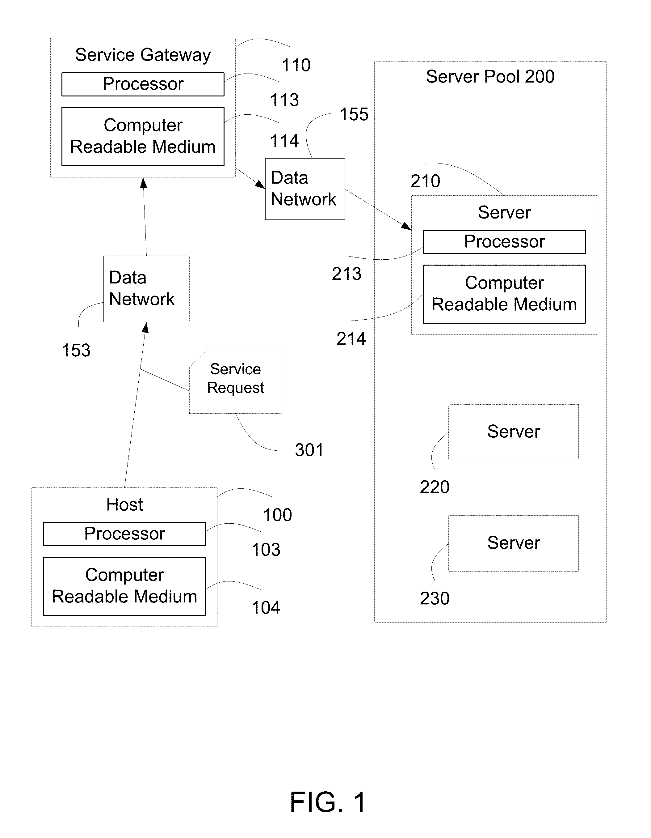
FIG. 1 illustrates an embodiment of a service gateway and an embodiment of the server pool according to the present invention.
FIG. 2 is a block diagram illustrating an embodiment of the processing of service requests by the service gateway.
FIG. 3 illustrates possible values for server status.
FIG. 4 is a block diagram illustrating an embodiment of the processing of service requests by the service gateway after receiving server status.
FIG. 5 illustrates the service gateway processing the service request according to service priorities.
FIG. 6 illustrates an embodiment of processing service requests by the service gateway 110.
FIG. 7 is a flowchart illustrating an embodiment of the method for processing service requests by the service gateway.
DETAILED DESCRIPTION OF THE INVENTION
The following description is presented to enable one of ordinary skill in the art to make and use the invention and is provided in the context of a patent application and its requirements. Various modifications to the embodiment will be readily apparent to those skilled in the art and the generic principles herein may be applied to other embodiments. Thus, the present invention is not intended to be limited to the embodiment shown but is to be accorded the widest scope consistent with the principles and features described herein.
The invention can take the form of an entirely hardware embodiment, an entirely software embodiment or an embodiment containing both hardware and software elements. In a preferred embodiment, the invention is implemented in software, which includes but is not limited to firmware, resident software, microcode, etc.
Furthermore, the invention can take the form of a computer program product accessible from a computer-usable or computer-readable medium providing program code for use by or in connection with a computer or any instruction execution system. For the purposes of this description, a computer-usable or computer readable medium can be any apparatus that can contain, store, communicate, propagate, or transport the program for use by or in connection with the instruction execution system, apparatus, or device.
The medium can be an electronic, magnetic, optical, electromagnetic, infrared, or semiconductor system (or apparatus or device) or a propagation medium. Examples of a computer-readable medium include a semiconductor or solid state memory, magnetic tape, a removable computer diskette, a random access memory (RAM), a read-only memory (ROM), a rigid magnetic disk and an optical disk. Current examples of optical disks include compact disk-read only memory (CD-ROM), compact disk-read/write (CD-R/W) and DVD.
A data processing system suitable for storing and/or executing program code will include at least one processor coupled directly or indirectly to memory elements through a system bus. The memory elements can include local memory employed during actual execution of the program code, bulk storage, and cache memories which provide temporary storage of at least some program code in order to reduce the number of times code must be retrieved from bulk storage during execution.
Input/output or I/O devices (including but not limited to keyboards, displays, point devices, etc.) can be coupled to the system either directly or through intervening I/O controllers.
Network adapters may also be coupled to the system to enable the data processing system to become coupled to other data processing systems or remote printers or storage devices through intervening private or public networks. Modems, cable modem and Ethernet cards are just a few of the currently available types of network adapters.
The flowchart and block diagrams in the figures illustrate the architecture, functionality, and operation of possible implementations of systems, methods and computer program products according to various embodiments of the present invention. In this regard, each block in the flowchart or block diagrams may represent a module, segment, or portion of code, which comprises one or more executable instructions for implementing the specified local function(s). It should also be noted that, in some alternative implementations, the functions noted in the block may occur out of the order noted in the figures. For example, two blocks shown in succession may, in fact, be executed substantially concurrently, or the blocks may sometimes be executed in the reverse order, depending upon the functionality involved. It will also be noted that each block of the block diagrams and/or flowchart illustration, and combinations of blocks in the block diagrams and/or flowchart illustration, can be implemented by special purpose hardware-based systems that perform the specified functions or acts, or combinations of special purpose hardware and computer instructions.
The terminology used herein is for the purpose of describing particular embodiments only and is not intended to be limiting of the invention. As used herein, the singular forms "a", "an" and "the" are intended to include the plural forms as well, unless the context clearly indicates otherwise. It will be further understood that the terms "comprises" and/or "comprising," when used in this specification, specify the presence of stated features, integers, steps, operations, elements, and/or components, but do not preclude the presence or addition of one or more other features, integers, steps, operations, elements, components, and/or groups thereof.
FIG. 1 illustrates an embodiment of the service gateway 110 and an embodiment of the server pool 200 according to the present invention. The service gateway 110 receives a service request 301 from a host 100. Service request 301 is delivered over a data network 153. In one embodiment, service request 301 is a Web service request such as an HTTP (Hypertext Transport Protocol) request, a secure HTTP request, an FTP (File Transfer Protocol) request, a file transfer request, an SIP (Session Initiation Protocol) session request, a request based on Web technology, a video or audio streaming request, a Web conferencing session request, or any request over the Internet or corporate network.
Host 100 is a computing device with network access capabilities. The host 100 is operationally coupled to a processor 103 and a computer readable medium 104. The computer readable medium 104 stores computer readable program code for implementing the various embodiments of the present invention as described herein. In one embodiment, host 100 is a workstation, a desktop personal computer or a laptop personal computer. In one embodiment, host 100 is a Personal Data Assistant (PDA), a smartphone, or a cellular phone. In one embodiment, host 100 is a set-top box, an Internet media viewer, an Internet media player, a smart sensor, a smart medical device, a net-top box, a networked television set, a networked DVR, a networked Blu-ray player, or a media center.
In one embodiment, data network 153 is an Internet Protocol (IP) network. In one embodiment, data network 153 is a corporate data network or a regional corporate data network. In one embodiment, data network 153 is an Internet service provider network. In one embodiment, data network 153 is a residential data network. In one embodiment, data network 153 includes a wired network such as Ethernet. In one embodiment, data network 153 includes a wireless network such as a WiFi network, or cellular network.
The service gateway 110 is operationally coupled to a processor 113 and a computer readable medium 114. The computer readable medium 114 stores computer readable program code, which when executed by the processor 113, implements the various embodiments of the present invention as described herein. In some embodiments, service gateway 110 is implemented as a server load balancer, an application delivery controller, a service delivery platform, a traffic manager, a security gateway, a component of a firewall system, a component of a virtual private network (VPN), a load balancer for video servers, or a gateway to distribute load to a plurality of servers.
Server pool 200 comprises a plurality of servers, for example server 210. Server 210 is operationally coupled to a processor 213 and a computer readable medium 214. The computer readable medium 214 stores computer readable program code, which when executed by the processor 213, implements the various embodiments of the present invention as described herein. In some embodiments, the computer readable program code implements server 210 as a Web server, a file server, a video server, a database server, an application server, a voice system, a conferencing server, a media gateway, an SIP server, a remote access server, a VPN server, or a media center.
In one embodiment, server pool 200 further includes server 220 and server 230. In an embodiment, server pool 200 is located in a datacenter, a server room, or an office. In an embodiment, the plurality of servers in server pool 200 may be located geographically over several locations or several datacenters. Service gateway 110 connects to server pool 200 via data network 155. In one embodiment, data network 155 is the same as data network 153. In one embodiment, data network 155 is different from data network 153. In one embodiment, host 100 does not have direct access to data network 155. In one embodiment, host 100 has direct access to data network 155.
FIG. 2 is a block diagram illustrating an embodiment of the processing of service requests by the service gateway 110. Based on information in service request 301, service gateway 110 selects server 210 to process service request 301. In one embodiment, service request 301 includes a Universal Resource Location (URL) 311.
Service gateway 110 selects server 210 based on service request URL 311. Server pool 200 is configured to process service request 301 efficiently, by using service request URL 311. The servers in the server pool 200 are configured as primary servers for particular URL's, and as secondary servers for other URLs. In an embodiment, server 210 is configured as a primary server for URL 311, whereas server 220 is configured as a secondary server for URL 311. In this embodiment, service gateway 110 preferably selects server 210 to process service request 301 as server 210 is configured as the primary server for URL 311. Service gateway 110 may select server 220 under certain circumstances to process service request 301 as server 220 is configured as the secondary server for URL 311. In one embodiment, there is a second service request URL 312 corresponding to a second service request 302. Server 220 may be configured to process second service request 302 with request URL 312 as a primary server.
FIG. 7 is a flowchart illustrating an embodiment of the method for processing service requests by the service gateway 110. Referring to both FIGS. 2 and 7, service gateway 110 establishes service session 160 with server 210 and sends service request 301 to server 210 (700). Upon processing service request 301, server 210 sends a service response 321 to service gateway 110 (701). Server 210 includes in the service response 321 a server status 218. Server status 218 indicates the availability or the computing load status of server 210. In one embodiment, server status 218 reflects a load representing CPU utilization, memory utilization, network utilization, storage utilization or a combination of one or more of the utilizations. In general, server status 218 summarizes how busy server 210 is.
Service gateway 110 obtains the server status 218 from the service response 321 (702) and relays the service response 321 to host 100 (703). In one embodiment, service gateway 110 modifies the service response 321 by removing server status 218 from service response 321. The service gateway 110 then sends the modified service response to host 100.
Service response 321 includes a result from the servicing of the service request 301. The service response 321 further includes the server status 218 associated with a tag 324. Service gateway 110 identifies the tag 324 from service response 321 and extracts server status 218 associated with tag 324. In one embodiment, service request 301 is an HTTP request, and service response 321 is an HTTP response. In this embodiment, tag 324 is in the HTTP header of the HTTP response. In one embodiment, service response 321 includes an HTML document. In this embodiment, tag 324 is an HTML tag. In another embodiment, service response 321 includes an XML document, and tag 324 can be an XML tag. In one embodiment, service response 321 is an SIP response packet, and tag 324 is an SIP tag. In one embodiment, service response 321 is an FTP response, and tag 324 is a special FTP reply code.
FIG. 3 illustrates possible values for server status 218. Other values for the server status 218 may be configured according to the needs of the system. In one embodiment, a value of 0 for server status 218 indicates that server 210 is not busy. Server 210 can handle new requests without any delay. For example, if service gateway 110 receives service request 301 with a request URL 311, service gateway 110 will select server 210 to process service request 301.
A value of 1 for server status 218 indicates that server 210 is busy. While server 210 can continue to serve as a primary server for URL 311, server 210 cannot serve as a secondary server. For example, server 210 is configured as a secondary server for URL 312. If service gateway 110 receives service request 302 with a request URL 312, service gateway 110 does not select server 210 to process service request 302.
A value of 2 for server status 218 indicates that server 210 is very busy. In addition to indicating that server 210 cannot serve as a secondary server; the server status 218 of 2 also indicates that service gateway 110 should apply a restriction prior to selecting server 210 to process a new service request as a primary server. For example, if service gateway 110 receives service request 301 with a request URL 311, service gateway 110 applies restriction prior to selecting server 210 to process service request 301. The restriction will be explained in further details with reference to FIG. 4.
FIG. 4 is a block diagram illustrating an embodiment of the processing of service requests by the service gateway 110 after receiving server status 218. In one embodiment, service gateway 110 includes a service request buffer 331. Service request buffer 331 is configured to store service requests with request URL 311. In an embodiment, server 210 is configured as a primary server for URL 311 and as a secondary server for request URL 313. Service gateway 110 further includes service request buffer 332, which is configured to store service requests with request URL 313. In an example, service request buffer 332 includes service request 411 with request URL 313.
Service gateway 110 received server status 218 from server 210 in a service response to a previous service request according to FIG. 2 above. Referring to FIGS. 4 and 7, the service gateway 110 receives a next service request 410 from the host 100 (704). The service gateway 110 stores the service request 410 with request URL 311 in service request buffer 331 and processes service request 410 in service request buffer 331 according the value of server status 218.
In one embodiment, server status 218 has a value of 0, indicating server 210 is "not busy". Service gateway 110 examines (first) service request buffer 331 and finds service request 410 with (first) request URL 311 for which server 210 is configured as the primary server (705). Service gateway 110 selects server 210 and sends service request 410 to server 210 (707). In one embodiment, service request buffer 331 is empty when service gateway 110 receives the next service request with request URL 311. The service gateway 110 sends this service request to server 210 without placing it in the service request buffer 331.
In this embodiment with server status 218 of value 0, service gateway 110 examines (second) service request buffer 332 and finds service request 411 with (second) request URL 313 for which server 210 is configured as the secondary server (706). As server status 218 indicates server 210 is available to serve as a secondary server, service gateway 110 may select server 210 to process service request 411 (711).
In one embodiment, request buffer 332 is empty when service gateway 110 receives the next server request which includes request URL 313. Service gateway 110 may select server 210 to process this service request without placing it in the service request buffer 332.
In one embodiment, server status 218 has a value or 1, indicating server 210 is busy and is not available to serve as a secondary server for URL 313 but is available to serve as a primary server. Service gateway 110 examines service request buffer 331. In one embodiment, service gateway 110 finds service request 410 in service request buffer 331 (705). Service gateway 110 sends service request 410 to server 210 (708). In one embodiment, service request buffer 331 is empty when service gateway 110 receives the next service request which includes request URL 311. Service gateway 110 sends this service request to server 210 without placing it in service request buffer 331.
In this embodiment with server status 218 of value 1, service gateway 110 examines service request buffer 332 and finds service request 411 in service request buffer 332 (706). Service gateway 110 does not select server 210 to process service request 411 (712). Instead, the service gateway 110 may select another server in the server pool 200 to process the service request 411 (713). In one scenario, the service request buffer 332 is empty when the service gateway 110 receives the next service request which includes request URL 313. Service gateway 110 does not select server 210 to service request (712).
In one embodiment server status 218 is of value 2, indicating server 210 is "very busy". In this embodiment, server 210 is not capable of serving as a secondary server to URL 313 but may serve as a primary server with restrictions.
In this embodiment with server status 218 of value 2, service gateway 110 examines service request buffer 331 and finds service request 410 (705). Service gateway 110 does not automatically send request 410 to server 210. In one embodiment, service gateway 110 includes a timer 117. Service gateway 110 waits for the timer 117 to expire (709) before selecting server 210 and sending request 410 to server 210 (710). In one embodiment, service gateway 110 configures timer 117 after receiving service response 321 with server status 218 of value 2. Timer 117 may be configured for duration of, for example 1 minute, 30 seconds, 1 second, 400 milliseconds, 5 milliseconds, 300 microseconds, or any other duration such that service to service request 410 is not severely affected. In one embodiment, timer 117 duration is based on the session protocol time out duration for service request 410.
In one embodiment with server status 218 of value 2, service request buffer 331 is empty when service gateway 110 receives a next service request with request URL 311. Service gateway 110 stores this service request in service request buffer 331. At a later time when timer 117 expires, service gateway 110 examines service request buffer 331 and finds this service request (705). When the timer 117 expires (709), service gateway 110 selects the server 210 and sends this service request to server 210 (710). In one embodiment, service gateway 110 sets up timer 117 again after processing service request buffer 331. In one embodiment, service gateway 110 processes a plurality of requests in service request buffer 331 before setting timer 117 again. In one embodiment, service gateway 110 cancels timer 117 when service gateway 110 receives server status 218 of value 0 or 1.
In this embodiment with server status 218 of value 2, service gateway 110 examines service request buffer 332 and finds service request 411 in service request buffer 332 (706). Service gateway 110 does not select server 210 to process service request 411 (714). Instead, the service gateway 110 may select another server in the server pool 200 to process the service request 411 (713). In one embodiment, the service request buffer 332 is empty when the service gateway 110 receives the next service request which includes request URL 313. Service gateway 110 does not select server 210 to service the service request.
FIG. 5 illustrates the service gateway 110 processing the service request according to service priorities. Service priorities may be configured based on a variety of parameters, such as the request URL of the service request, the host from which the service request is sent, and the data network where service gateway 110 receives the service request. In one embodiment, the service priority association 550 between a priority and the parameter value is stored in service gateway 110. For example, priority 401 is associated with URL 311, and the association 550 between priority 401 and URL 311 is stored in service gateway 110. In another example, priority 401 is associated with host 100, such as the IP address of host 100 or the user identity of host 100, and the association 550 between the priority 401 and the host 100 is stored in service gateway 110. In another example, priority 401 is associated with the network interface from which service request 410 is received, and the association 550 between the priority 401 and the network interface is stored in service gateway 110. In one embodiment, service gateway 110 includes a datastore (not shown) storing the association 550. Service gateway 110 determines priority 401 for the service request 410 by matching the appropriate parameter of the service request 410 to the stored association 550.
In one embodiment, service gateway 110 includes service request buffer 333 configured to store service requests with request URL 311, and service request buffer 331 also configured to store service requests for URL 311. Service request buffer 333 is configured to store service requests with priority 403, which is higher than priority 401. Service request buffer 331 is configured to store service requests with priority 401. In one embodiment, the server status 218 has a value of 2, and service gateway 110 stores service request 410 with request URL 311 and priority 401 in service request buffer 331. Service gateway 110 further receives a service request 412 with request URL 311 and service priority 403. Service gateway 110 stores service request 412 in service request buffer 333.
When the timer 117 expires, service gateway 110 examines service request buffer 333 of higher priority 403 before examining service request buffer 331 of lower priority 401. In this example, service gateway 110 processes service request 410 before processing service request 412.
In one embodiment, service gateway 110 receives a new server status 219 for server 210 of value 0 or 1, and service gateway 110 continues to examine service request buffer 333 of higher priority 403 before examining service request buffer 331 of lower priority 401. In this example, service gateway 110 processes service request 412 before processing service request 410.
In one embodiment, service gateway 110 processes all service requests from service request buffer 333 before processing service request buffer 331, regardless of the value of the server status 218. In one embodiment, service gateway 110 includes a serving ratio 119 where service gateway 110 processes service requests in service request buffer 333 and service request buffer 331 according to ratio 119, where ratio 119 favors the higher priority service request buffer 333 to the lower priority service request buffer 331 in order to avoid starving the lower priority service requests in service request buffer 331.
In a preferred embodiment, server 210 is configured to serve as primary server for a plurality of URLs. FIG. 6 illustrates an embodiment of processing service requests by the service gateway 110. In one embodiment, a hashing function 502 is applied to URL 311 and URL 313. When hashing function 502 is applied to URL 311, the result is a hashed value 511. Similarly, when hashing function 502 is applied to URL 313, the result is a hashed value 513. In one embodiment, Server 210 is configured to serve as primary server for hashed value 520. In one embodiment, service gateway 110 stores hashing function 502 and hashed value 520. Examples for hashing function 502 include MD5 (Message-Digest algorithm 5) hashing function, a Jenkins hashing function, a hashing function applicable for a sequence of characters, or a hashing function for table lookup.
When service gateway 110 receives service request 410 with request URL 311. Service gateway 110 applies hashing function 502 to request URL 311 to yield hashed value 511. Service gateway 110 compares hashed value 511 to hashed value 520. If hashed value 511 matches hashed value 520, service gateway 110 selects server 210 to process service request 410 in the manner described above. In one embodiment, service gateway 110 receives service request 411 with request URL 313. Service gateway 110 applies hashing function 502 to request URL 313 to yield hashed value 513. Service gateway 110 compares hashed value 513 to hashed value 520. If hashed value 513 matches hashed value 520, service gateway 110 selects server 210 to process service request 411. In one embodiment, hashed value 513 does not match hashed value 520, and service gateway 110 does not automatically select server 210.
In one embodiment, server 210 is configured as a secondary server to hashed value 513. Service gateway 110 may select server 210. In one embodiment, server 210 is not configured to serve hashed value 513, and service gateway 110 does not select server 210 to process service request 411.
In this embodiment, service gateway 110 applies hashing function 502 to a service request when service gateway 110 processes the service request. Once the service gateway 110 determines that the server 210 is configured either as the primary or the secondary server to the hashed value 513, the service gateway 110 processes the service request 411 using the server status 218 as described above. One of ordinary skill in the art will understand how to combine the application of the hashing function to the process described above without departing from the spirit and scope of the present invention.
Although the present invention has been described in accordance with the embodiments shown, one of ordinary skill in the art will readily recognize that there could be variations to the embodiments and those variations would be within the spirit and scope of the present invention. Accordingly, many modifications may be made by one of ordinary skill in the art without departing from the spirit and scope of the appended claims.
* * * * *
References
D00000
D00001
D00002
D00003
D00004
D00005
D00006
D00007
XML
uspto.report is an independent third-party trademark research tool that is not affiliated, endorsed, or sponsored by the United States Patent and Trademark Office (USPTO) or any other governmental organization. The information provided by uspto.report is based on publicly available data at the time of writing and is intended for informational purposes only.
While we strive to provide accurate and up-to-date information, we do not guarantee the accuracy, completeness, reliability, or suitability of the information displayed on this site. The use of this site is at your own risk. Any reliance you place on such information is therefore strictly at your own risk.
All official trademark data, including owner information, should be verified by visiting the official USPTO website at www.uspto.gov. This site is not intended to replace professional legal advice and should not be used as a substitute for consulting with a legal professional who is knowledgeable about trademark law.