Vehicular ventilation module for use with a vehicular HVAC system
Connell Sept
U.S. patent number 10,414,243 [Application Number 15/791,243] was granted by the patent office on 2019-09-17 for vehicular ventilation module for use with a vehicular hvac system. This patent grant is currently assigned to BERGSTROM, INC.. The grantee listed for this patent is Bergstrom, Inc.. Invention is credited to Brett Sean Connell.


| United States Patent | 10,414,243 |
| Connell | September 17, 2019 |
| **Please see images for: ( Certificate of Correction ) ** |
Vehicular ventilation module for use with a vehicular HVAC system
Abstract
The disclosed embodiments include a vehicular ventilation module having control circuitry, a return air duct, a fresh air duct, a heat exchanger, and a door joining an upstream portion of the return air duct upstream of the heat exchanger and an upstream portion of the fresh air duct upstream of the heat exchanger. The fresh air duct has an air inlet and an air outlet downstream of the air inlet. The heat exchanger is thermally coupled to the return air duct upstream of the return air outlet and to the fresh air duct downstream of the return air inlet. The door selectively opens to enable air to pass between the fresh air duct and the return air duct. The control circuitry is configured to operate in a first mode of operation, including having the door open. The return air outlet is configured to provide air to the HVAC system.
| Inventors: | Connell; Brett Sean (Winnebago, IL) | ||||||||||
|---|---|---|---|---|---|---|---|---|---|---|---|
| Applicant: |
|
||||||||||
| Assignee: | BERGSTROM, INC. (Rockford,
IL) |
||||||||||
| Family ID: | 51522198 | ||||||||||
| Appl. No.: | 15/791,243 | ||||||||||
| Filed: | October 23, 2017 |
Prior Publication Data
| Document Identifier | Publication Date | |
|---|---|---|
| US 20180134117 A1 | May 17, 2018 | |
Related U.S. Patent Documents
| Application Number | Filing Date | Patent Number | Issue Date | ||
|---|---|---|---|---|---|
| 14209961 | Mar 13, 2014 | 9796239 | |||
| 61778854 | Mar 13, 2013 | ||||
| Current U.S. Class: | 1/1 |
| Current CPC Class: | F24F 12/006 (20130101); B60H 1/008 (20130101); B60H 1/00849 (20130101); B60H 1/00378 (20130101); B60H 1/00457 (20130101); B60H 1/00785 (20130101); B60H 1/00321 (20130101); B60H 1/039 (20190501); B60H 1/03 (20130101); F24F 13/04 (20130101) |
| Current International Class: | B60H 1/00 (20060101); F24F 12/00 (20060101); B60H 1/03 (20060101); F24F 13/04 (20060101) |
References Cited [Referenced By]
U.S. Patent Documents
| 2722050 | November 1955 | Shank |
| 2789234 | June 1956 | Lambert et al. |
| 3176502 | April 1965 | Cizek |
| 3225819 | December 1965 | Stevens |
| 3590910 | July 1971 | Lorenz |
| 3627030 | December 1971 | Lorenz |
| 3807087 | April 1974 | Staats |
| 3844130 | October 1974 | Wahnish |
| 3880224 | April 1975 | Weil |
| 3885398 | May 1975 | Dawkins |
| 3948060 | April 1976 | Gaspard |
| 3995443 | December 1976 | Iversen |
| 4015182 | March 1977 | Erdman |
| 4034801 | July 1977 | Bernstein |
| 4071080 | January 1978 | Bridgers |
| 4217764 | August 1980 | Armbruster |
| 4271677 | June 1981 | Harr |
| 4280330 | July 1981 | Harris et al. |
| 4324286 | April 1982 | Brett |
| 4359875 | November 1982 | Ohtani |
| 4391321 | July 1983 | Thunberg |
| 4412425 | November 1983 | Fukami |
| 4448157 | May 1984 | Eckstein et al. |
| 4459519 | July 1984 | Erdman |
| 4577679 | March 1986 | Hibshman |
| 4604036 | August 1986 | Sutou et al. |
| 4617472 | October 1986 | Slavik |
| 4641502 | February 1987 | Aldrich et al. |
| 4658593 | April 1987 | Stenvinkel |
| 4667480 | May 1987 | Bessler |
| 4694798 | September 1987 | Kato et al. |
| 4748825 | June 1988 | King |
| 4825663 | May 1989 | Nijar et al. |
| 4841733 | June 1989 | Dussault |
| 4856078 | August 1989 | Konopka |
| 4893479 | January 1990 | Gillett et al. |
| 4905478 | March 1990 | Matsuda et al. |
| 4945977 | August 1990 | D'Agaro |
| 4947657 | August 1990 | Kalmbach |
| 4952283 | August 1990 | Besik |
| 4982576 | January 1991 | Proctor et al. |
| 5025634 | June 1991 | Dressler |
| 5046327 | September 1991 | Walker |
| 5067652 | November 1991 | Enander |
| 5095308 | March 1992 | Hewitt |
| 5125236 | June 1992 | Clancey et al. |
| 5170639 | December 1992 | Datta |
| 5230719 | July 1993 | Berner |
| 5275012 | January 1994 | Dage et al. |
| 5307645 | May 1994 | Pannell |
| 5316074 | May 1994 | Isaji et al. |
| 5324229 | June 1994 | Weisbecker |
| 5333678 | August 1994 | Mellum et al. |
| 5361593 | November 1994 | Dauvergne |
| 5376866 | December 1994 | Erdman |
| 5396779 | March 1995 | Voss |
| 5402844 | April 1995 | Elluin |
| 5404730 | April 1995 | Westermeyer |
| 5426953 | June 1995 | Meckler |
| 5465589 | November 1995 | Bender et al. |
| 5497941 | March 1996 | Numazawa et al. |
| 5501267 | March 1996 | Iritani et al. |
| 5502365 | March 1996 | Nanbu et al. |
| 5524442 | June 1996 | Bergmen, Jr. et al. |
| 5528901 | June 1996 | Willis |
| 5562538 | October 1996 | Suyama |
| 5586613 | December 1996 | Ehsani |
| 5647534 | July 1997 | Kelz |
| 5657638 | August 1997 | Erdman et al. |
| 5682757 | November 1997 | Peterson |
| 5720181 | February 1998 | Karl |
| 5752391 | May 1998 | Ozaki et al. |
| 5761918 | June 1998 | Jackson et al. |
| 5775415 | July 1998 | Yoshimi |
| 5782610 | July 1998 | Ikeda |
| 5819549 | October 1998 | Sherwood |
| 5896750 | April 1999 | Karl |
| 5898995 | May 1999 | Ghodbane |
| 5899081 | May 1999 | Evans et al. |
| 5901572 | May 1999 | Peiffer et al. |
| 5901780 | May 1999 | Zeigler et al. |
| 5921092 | July 1999 | Behr et al. |
| 5934089 | August 1999 | Magakawa et al. |
| 5982643 | November 1999 | Phlipot |
| 5996363 | December 1999 | Kurachi et al. |
| 6016662 | January 2000 | Tanaka et al. |
| 6028406 | February 2000 | Birk |
| 6029465 | February 2000 | Bascobert |
| 6038877 | March 2000 | Peiffer et al. |
| 6038879 | March 2000 | Turcotte |
| 6059016 | May 2000 | Rafalovich et al. |
| 6073456 | June 2000 | Kawai et al. |
| 6111731 | August 2000 | Cepynsky |
| 6112535 | September 2000 | Hollenbeck |
| 6125642 | October 2000 | Seener et al. |
| 6134901 | October 2000 | Harvest et al. |
| 6152217 | November 2000 | Ito et al. |
| 6185959 | February 2001 | Zajac |
| 6193475 | February 2001 | Rozek |
| 6205795 | March 2001 | Backman et al. |
| 6205802 | March 2001 | Drucker et al. |
| 6209333 | April 2001 | Bascobert |
| 6209622 | April 2001 | Lagace |
| 6213867 | April 2001 | Yazici |
| 6230507 | May 2001 | Ban et al. |
| 6253563 | July 2001 | Ewert et al. |
| 6265692 | July 2001 | Umebayahi |
| 6276161 | August 2001 | Peiffer et al. |
| 6282919 | September 2001 | Rockenfeller |
| 6351957 | March 2002 | Hara |
| 6405793 | June 2002 | Ghodbane et al. |
| 6411059 | June 2002 | Frugier et al. |
| 6453678 | September 2002 | Sundhar |
| 6457324 | October 2002 | Zeigler et al. |
| 6467279 | October 2002 | Backman et al. |
| 6474081 | November 2002 | Feuerecker |
| 6530426 | March 2003 | Kishita et al. |
| 6543245 | April 2003 | Waldschmidt |
| 6571566 | June 2003 | Temple et al. |
| 6575228 | June 2003 | Ragland |
| 6626003 | September 2003 | Kortum et al. |
| 6675601 | January 2004 | Ebara |
| 6684863 | February 2004 | Dixon et al. |
| 6725134 | April 2004 | Dillen et al. |
| 6745585 | June 2004 | Kelm et al. |
| 6748750 | June 2004 | Choi |
| 6758049 | July 2004 | Adachi et al. |
| 6889762 | May 2005 | Zeigler et al. |
| 6932148 | August 2005 | Brummett et al. |
| 6939114 | September 2005 | Iwanami et al. |
| 6965818 | November 2005 | Koenig et al. |
| 6981544 | January 2006 | Iwanami et al. |
| 7150159 | December 2006 | Brummett et al. |
| 7246502 | July 2007 | Hammonds et al. |
| 7316119 | January 2008 | Allen |
| 7350368 | April 2008 | Heberle et al. |
| 7591143 | September 2009 | Zeigler et al. |
| 7591303 | September 2009 | Ziegler et al. |
| 7614242 | November 2009 | Quesada Saborio |
| 7637031 | December 2009 | Salim |
| 7765824 | August 2010 | Wong et al. |
| 8001799 | August 2011 | Obayashi et al. |
| 8141377 | March 2012 | Connell et al. |
| 8156754 | April 2012 | Hong et al. |
| 8276892 | October 2012 | Narikawa |
| 8517087 | August 2013 | Zeigler et al. |
| 8821092 | September 2014 | Nambara et al. |
| 8905071 | December 2014 | Coombs et al. |
| 8919140 | December 2014 | Johnson et al. |
| 8947531 | February 2015 | Fischer et al. |
| 9157670 | October 2015 | Kreeley |
| 9216628 | December 2015 | Self et al. |
| 9783024 | October 2017 | Connell et al. |
| 9878591 | January 2018 | Taniguchi |
| 2001/0010261 | August 2001 | Oomura et al. |
| 2002/0020183 | February 2002 | Hayashi |
| 2002/0026801 | March 2002 | Yamashita |
| 2002/0036081 | March 2002 | Ito |
| 2002/0042248 | April 2002 | Vincent |
| 2002/0078700 | June 2002 | Kelm et al. |
| 2002/0084769 | July 2002 | Iritani et al. |
| 2002/0108384 | August 2002 | Higashiyama |
| 2002/0112489 | August 2002 | Egawa et al. |
| 2002/0157412 | October 2002 | Iwanami et al. |
| 2002/0157413 | October 2002 | Iwanami et al. |
| 2003/0041603 | March 2003 | Tada et al. |
| 2003/0105567 | June 2003 | Koenig et al. |
| 2003/0106332 | June 2003 | Okamoto |
| 2004/0060312 | April 2004 | Horn et al. |
| 2004/0168449 | September 2004 | Homan et al. |
| 2004/0216477 | November 2004 | Yamasaki et al. |
| 2004/0221599 | November 2004 | Hille et al. |
| 2004/0256082 | December 2004 | Bracciano |
| 2005/0016196 | January 2005 | Kadle et al. |
| 2005/0109499 | May 2005 | Iwanami et al. |
| 2005/0161211 | July 2005 | Zeigler et al. |
| 2005/0230096 | October 2005 | Yamaoka |
| 2005/0235660 | October 2005 | Pham |
| 2005/0257545 | November 2005 | Ziehr et al. |
| 2006/0042284 | March 2006 | Heberle et al. |
| 2006/0080980 | April 2006 | Lee et al. |
| 2006/0102333 | May 2006 | Zeigler et al. |
| 2006/0118290 | June 2006 | Klassen |
| 2006/0151163 | July 2006 | Zeigler et al. |
| 2006/0151164 | July 2006 | Zeigler et al. |
| 2006/0254309 | November 2006 | Takeuchi et al. |
| 2007/0070605 | March 2007 | Straznicky et al. |
| 2007/0101760 | May 2007 | Bergander |
| 2007/0131408 | June 2007 | Zeigler et al. |
| 2007/0144723 | June 2007 | Aubertin et al. |
| 2007/0144728 | June 2007 | Kinmartin |
| 2007/0163276 | July 2007 | Braun et al. |
| 2007/0227167 | October 2007 | Shapiro |
| 2007/0295017 | December 2007 | Pannell |
| 2008/0017347 | January 2008 | Chung |
| 2008/0110185 | May 2008 | Veettil et al. |
| 2008/0156887 | July 2008 | Stanimirovic |
| 2008/0196436 | August 2008 | Connell |
| 2008/0196877 | August 2008 | Zeigler et al. |
| 2008/0209924 | September 2008 | Yoon et al. |
| 2009/0211280 | August 2009 | Alston |
| 2009/0229288 | September 2009 | Alston et al. |
| 2009/0241592 | October 2009 | Stover |
| 2009/0249802 | October 2009 | Nemesh et al. |
| 2009/0301702 | December 2009 | Zeigler et al. |
| 2010/0009620 | January 2010 | Kawato |
| 2010/0019047 | January 2010 | Flick |
| 2010/0218530 | September 2010 | Melbostad et al. |
| 2010/0263395 | October 2010 | Adachi |
| 2010/0293966 | November 2010 | Yokomachi et al. |
| 2011/0088417 | April 2011 | Kayser |
| 2011/0120146 | May 2011 | Ota |
| 2011/0126566 | June 2011 | Jones et al. |
| 2011/0174014 | July 2011 | Scarcella et al. |
| 2011/0308265 | December 2011 | Phannavong |
| 2012/0023982 | February 2012 | Berson et al. |
| 2012/0102779 | May 2012 | Beers et al. |
| 2012/0118532 | May 2012 | Jentzsch et al. |
| 2012/0133176 | May 2012 | Ramberg |
| 2012/0247135 | October 2012 | Fakieh |
| 2012/0297805 | November 2012 | Kamada et al. |
| 2012/0318014 | December 2012 | Huff et al. |
| 2013/0040549 | February 2013 | Douglas |
| 2013/0167577 | July 2013 | Street |
| 2013/0319630 | December 2013 | Yamamoto |
| 2014/0066572 | March 2014 | Corveleyn |
| 2014/0075973 | March 2014 | Graaf |
| 2014/0241926 | August 2014 | Fraser |
| 2014/0290299 | October 2014 | Nakaya |
| 2015/0059367 | March 2015 | Emo et al. |
| 2015/0158368 | June 2015 | Herr-Rathke et al. |
| 2015/0210287 | July 2015 | Penilla et al. |
| 2015/0236525 | August 2015 | Aridome |
| 2015/0239365 | August 2015 | Hyde et al. |
| 2015/0306937 | October 2015 | Kitamura et al. |
| 2016/0089958 | March 2016 | Powell |
| 2016/0144685 | May 2016 | Ochiai |
| 2016/0146554 | May 2016 | Bhatia et al. |
| 2016/0229266 | August 2016 | Maeda |
| 2017/0211855 | July 2017 | Fraser et al. |
| 2017/0350632 | December 2017 | Hirao et al. |
| 1468409 | Jan 2004 | CN | |||
| 201872573 | Jun 2011 | CN | |||
| 102398496 | Apr 2012 | CN | |||
| 103547466 | Jan 2014 | CN | |||
| 104105610 | Oct 2014 | CN | |||
| 4440044 | May 1996 | DE | |||
| 10014483 | Nov 2000 | DE | |||
| 102005004950 | Aug 2006 | DE | |||
| 10 2007 028851 | Dec 2008 | DE | |||
| 102010054965 | Jun 2012 | DE | |||
| 0516413 | Dec 1992 | EP | |||
| 0958952 | Nov 1999 | EP | |||
| 1024038 | Aug 2000 | EP | |||
| 1 477 748 | Nov 2004 | EP | |||
| 1 700 725 | Sep 2006 | EP | |||
| 1 703 231 | Sep 2006 | EP | |||
| 1 970 651 | Sep 2008 | EP | |||
| 2048011 | Apr 2009 | EP | |||
| 2196748 | Jun 2010 | EP | |||
| 2320160 | May 2011 | EP | |||
| 2894420 | Jul 2015 | EP | |||
| 0963895 | Dec 2015 | EP | |||
| 2966391 | Apr 2012 | FR | |||
| H02-128915 | May 1990 | JP | |||
| 5032121 | Feb 1993 | JP | |||
| H07186711 | Jul 1995 | JP | |||
| H97-76740 | Mar 1997 | JP | |||
| H09318177 | Dec 1997 | JP | |||
| H10281595 | Oct 1998 | JP | |||
| 2000108651 | Apr 2000 | JP | |||
| 2005044551 | Apr 2000 | JP | |||
| 2002081823 | Mar 2002 | JP | |||
| 2006-264568 | Oct 2006 | JP | |||
| 2008220043 | Sep 2008 | JP | |||
| 2012017029 | Jan 2012 | JP | |||
| 2014226979 | Dec 2014 | JP | |||
| 20090068136 | Jun 2009 | KR | |||
| WO 89/09143 | Oct 1989 | WO | |||
| WO 99/61269 | Dec 1999 | WO | |||
| WO 00/00361 | Jan 2000 | WO | |||
| WO 2006/082082 | Aug 2006 | WO | |||
| WO 2012/158326 | Nov 2012 | WO | |||
| WO 2014/112320 | Jul 2014 | WO | |||
| WO 2014/180749 | Nov 2014 | WO | |||
| WO 2014/209780 | Dec 2014 | WO | |||
| WO 2015/076872 | May 2015 | WO | |||
Other References
|
Alfa Laval Website http://www.alfalaval.com/ecore-Java/WebObjects/ecoreJava.woa/wa/shoNode?s- iteNodelID=1668&cont...; date last visited May 18, 2007; 1 page. cited by applicant . Anonymous: "NITE Connected Climate Controlled Transport Monitoring/Mobile Internet of Things UI Design/Mobil UI: Progress/Printeres/Internet of Things, User Inter . . . ," Oct. 19, 2016 retrieved from: URL:htps://za.pinterest.com/pin/192810427773981541/, 1 pg. cited by applicant . Bergstrom, Inc., International Search Report and Written Opinion, PCT/US2014/026687, dated Jul. 28, 2014, 12 pgs. cited by applicant . Bergstrom, Inc., International Preliminary Report on Patentability, PCT/US2014/026687, dated Sep. 15, 2015, 7 pgs. cited by applicant . Bergstrom, Inc., International Search Report and Written Opinion, PCT/US2014/026683, dated Jul. 3, 2014 12 pgs. cited by applicant . Bergstrom, Inc., International Preliminary Report on Patentability, PCT/US2014/026683, dated Sep. 15, 2015, 6pgs. cited by applicant . Bergstrom, Inc., International Search Report and Written Opinion, PCT/US2013/068331, dated Nov. 7, 2014, 9 pgs. cited by applicant . Bergstrom, Inc., International Preliminary Report on Patentability, PCT/US2013/068331, dated May 10, 2016, 6 pgs. cited by applicant . Bergstrom, Inc., International Search Report and Written Opinion, PCT/US2016/021602, dated Nov. 3, 2016, 7 pgs. cited by applicant . Bergstrom, Inc., International Preliminary Report on Patentability, PCT/US2016/021602, dated Sep. 12, 2017, 11 pgs. cited by applicant . Bergstrom, Inc., International Search Report and Written Opinion, PCT/US2017/021346, dated Jul. 25, 2017, 11 pgs. cited by applicant . Bergstrom, Inc., International Search Report and Written Opinion, PCT/US2016/065812, dated Mar. 22, 2017, 12 pgs. cited by applicant . Bergstrom, Inc., International Preliminary Report on Patentability, PCT/US2016/065812, dated Jun. 12, 2018, 8 pgs. cited by applicant . Bergstrom, Inc., International Search Report and Written Opinion, PCT/US2018/044093, dated Oct. 25, 2018, 13 pgs. cited by applicant . Bergstrom, Inc., Communication Pursuant to Rules 161(2) and 162 EPC, EP14717604.4, dated Oct. 23, 2015, 2 pgs. cited by applicant . Bergstrom, Inc., Communication Pursuant to Article 94(3), EP14717604.4, dated Jun. 2, 2017, 12 pgs. cited by applicant . Bergstrom, Inc., Communication Pursuant to Rules 161(2) and 162 EPC, EP14722438.0, dated Nov. 2, 2015. 2 pgs. cited by applicant . Bergstrom, Inc. Communication Pursuant to Article 94(3), EP14722438.0, dated Jan. 24, 2018, 5 pgs. cited by applicant . Bergstrom, Inc., Communication Pursuant to Rules 161(2) and 162 EPC, EP13795064.8, dated Jun. 22, 2016, 2 pgs. cited by applicant . Bergstrom, Inc. Extended European Search Report, EP16204254.3, dated Jul. 25, 2017, 8 pgs. cited by applicant . Bergstrom, Inc. Partial European Search Report, EP16204259.2, dated May 30, 2017, 14 pgs. cited by applicant . Bergstrom, Inc. Extended European Search Report, EP16204259.2, dated Oct. 25, 2017, 15 pgs. cited by applicant . Bergstrom, Inc. Corrected Extended European Search Report, EP16204259.2, dated Nov. 24, 2017, 15 pgs. cited by applicant . Bergstrom, Inc. Partial European Search Report, EP16204256.8, dated Jul. 13, 2017, 14 pgs. cited by applicant . Bergstrom, Inc. Extended European Search Report, EP16204256.8, dated Jan. 12, 2018, 11 pgs. cited by applicant . Bergstrom, Inc. Extended European Search Report, EP16204256.8, dated Dec. 1, 2017, 13 pgs. cited by applicant . Bergstrom, Inc. Extended European Search Report, EP16204267.5, dated Jul. 11, 2017, 8 pgs. cited by applicant . Bergstrom, Inc. Extended European Search Report, EP18177850.7, dated Nov. 28, 2018. 8 pgs. cited by applicant . Bergstrom, Inc., Office Action, CN201480027137.4, dated Mar. 3, 2017, 15 pgs. cited by applicant . Bergstrom, Inc., 2nd Office Action, CN201480027137.4, dated Jul. 13, 2017, 10 pgs. cited by applicant . Bergstrom, Inc., 3rd Office Action, CN201480027137.4, dated Jan. 17, 2018, 19 pgs. cited by applicant . Bergstrom, Inc., 4th Office Action, CN201480027137.4, dated Jul. 26, 2018, 8 pgs. cited by applicant . Bergstrom, Inc., Office Action, CN201480027117.7, dated Mar. 9, 2017, 8 pgs. cited by applicant . Bergstrom, Inc., Patent Certificate, CN201480027117.7, Nov. 21, 2017, 3 pgs. cited by applicant . Bergstrom, Inc., 2nd Office Action, CN201380081940.1, dated Jan. 17, 2018, 13 pgs. cited by applicant . Bergstrom, Inc., 3rd Office Action, CN201380081940.1, dated Jul. 30, 2018, 7 pgs. cited by applicant . Connell, Office Action, U.S. Appl. No. 14/209,877, dated Nov. 27, 2015, 19 pgs. cited by applicant . Connell, Final Office Action, U.S. Appl. No. 14/209,877, dated Jun. 22, 2016, 17 pgs. cited by applicant . Connell, Final Office Action, U.S. Appl. No. 14/209,877, dated Dec. 29, 2016, 21 pgs. cited by applicant . Connell, Notice of Allowance, U.S. Appl. No. 14/209,877, dated May 16, 2017, 5 pgs. cited by applicant . Connell, Notice of Allowance, U.S. Appl. No. 14/209,877, dated Aug. 4, 2017, 7 pgs. cited by applicant . Connell, Office Action, U.S. Appl. No. 14/209,961, dated Dec. 2, 2015, 14 pgs. cited by applicant . Connell, Final Office Action, U.S. Appl. No. 14/209,961, dated Jul. 25, 2016, 15 pgs. cited by applicant . Connell, Notice of Allowance, U.S. Appl. No. 14/209,961, dated Jun. 15, 2017, 10 pgs. cited by applicant . Connell, Notice of Allowance, U.S. Appl. No. 15/064,552, dated Jun. 1, 2017, 9 pgs. cited by applicant . Connell, Notice of Allowance, U.S. Appl. No. 14/995,119, dated Aug. 31, 2017, 7 pgs. cited by applicant . Connell, Office Action, U.S. Appl. No. 14/965,142, dated Aug. 29, 2017, 12 pgs. cited by applicant . Connell, Notice of Allowance, U.S. Appl. No. 14/965,142, dated Feb. 26, 2018, 8 pgs. cited by applicant . Connell, Office Action, U.S. Appl. No. 15/280,876, dated Dec. 14, 2017, 23 pgs. cited by applicant . Connell, Notice of Allowance, U.S. Appl. No. 15/280,876, dated Jun. 21, 2018, 8 pgs. cited by applicant . Connell, Office Action, U.S. Appl. No. 15/791,243, dated May 8, 2018, 12 pgs. cited by applicant . Connell, Office Action, U.S. Appl. No. 15/065,745, dated May 31, 2018, 44 pgs. cited by applicant . Connell, Office Action, U.S. Appl. No. 15/722,860, dated Oct. 19, 2018, 7 pgs. cited by applicant . Connell, Office Action, U.S. Appl. No. 15/283,150, dated Sep. 27, 2018, 21pgs. cited by applicant . FlatPlate Heat Exchangers; GEA FlatPiate Inc.; website--http://www.flatplate.com/profile.html; date last visited Aug. 9, 2007; 3 pages. cited by applicant . Glacier Bay Inc., Glacier Bay's Home Page, page printed from a website, htt(?:/web.archive.org/web/19990417062255/htt[2://www.glacierbay.com/, apparent archive date: Apr. 17, 1999, 1 page. cited by applicant . Glacier Bay Inc., Darpa/Glacier Bay ECS, pages printed from a website, httir//web.archive.org/web/19991104132941/wvvw .glacierbay.com/darQatxt. htm, apparent archive date: Nov. 4, 1999, 2 pages. cited by applicant . Glacier Bay Inc., Glacier Bay ECS DARPA Project--Final Report, pages printed from a website, httn://web.archive.or_gjweb/19991103001512/v vww ,_g.Jacierbay.com/Darnhtm.htm, apparent archive date: Nov. 3, 1999, 9 pages. cited by applicant . Glacier Bay Inc., Glacier Bay ECS DARPA Project--Project Photos, pages printed from a website, httg://web.archive.org/web/1999 1103012854/www.glacierbay.com/Dargghotos.htm, apparent archive date: Nov. 3, 1999, 2 pages. cited by applicant . Glacier Bay Inc., Glacier Bay ECS DARPA Project--Operational Video, page printed from a website, httQ://web.archive.orq/web/19991022221040/wvvw.qlacierbay.com/DarQvid.htm- , apparent archive date Oct. 22, 1999; 1 page. cited by applicant . Glacier Bay Inc., R & D, pages printed from a website, htt ://web.archive.org/web/20000121130306/www.glacierbay.com/R&D.htm, apparent archive date: Jan. 21, 2000, 2 pages. cited by applicant . Glacier Bay Inc., Company History, pages printed from a website, httg://web.archive.org/web/20000301153828/www .g!acierbay.corn/History:.htrn, apparent archive date: Mar. 1, 2000; 2 pages. cited by applicant . Glacier Bay Inc., Contact, page printed from .a website, httQ://web.archive.orq/web/19990508104511/W\'''I !V .qlacierba:t.com/Contact.htm, apparent archive date: May 8, 1999; 1 page. cited by applicant . Hansson, Office Action dated Oct. 5, 2018, U.S. Appl. No. 15/256,109, 14 pgs. cited by applicant . Michael Lohle, Gunther Feuerecker and Ulrich Salzer; NON Idling HVAC-modufe tor Long Distance Trucks;SAE TechnicalPaper Series 1999-01-1193; International Congress and Exposition, Detroit, Michigan; Mar. 1-4, 1999; 8 pages. cited by applicant . Mahmoud Ghodbane; On Vehicle Performance of a Secondary Loop A/C System; SAE Technical Paper Series 2000-01-1270; SAE 2000 World Congress, Detroit, Michigan; Mar. 6-9, 2000; 6 pages. cited by applicant . Masami Konaka and Hiroki Matsuo; SAE Technical Paper Series 2000-01-1271; SAE 2000 World Congress, Detroit, Michigan; Mar. 6-9, 2000; 7 pages. cited by applicant . Mayo Mayo, Office Action, U.S. Appl. No. 15/034,517, dated Feb. 21, 2018, 22 pgs. cited by applicant . Mayo Mayo, Final Office Action, U.S. Appl. No. 15/034,517, dated Aug. 28, 2018, 9pgs. cited by applicant . Frank Stodolsky, Linda Gaines, and Anant Vyas; Analysis of Technology Options to Reduce the Fuel Consumption of Idling Trucks; Paper-Center for Transportation Research, Energy Systems Division, Argonne National Laboratory,9700 South Cass Avenue, Argonne, Illinois 60439;Jun. 2000; 30 pages. cited by applicant . Paper No. 26 in IPR2012-00027, Jun. 11, 2013, 12 pgs. (U.S. Pat. No. 7,591,303). cited by applicant . Patricia Gardie and Vincent Goetz; Thermal Energy Storage System by Solid Absorption for Electric Automobile Heating and Air-Conditioning; Paper; 1995, 5 pages. cited by applicant . TropiCool No-idle Heating & Cooling, 110V/12V High-efficiency, Self-contained, Electrified Heating/AC System; ACC Climate Control Brochure, Elkhart, Indiana; 2005, 1 page. cited by applicant . TropiCool Power Plus, More comfort. More efficiency. More options.; ACC Climate Control Brochure, Elkhart, Indiana; 2006, 3 pages. cited by applicant . Packless Industries, the leader in refrigerant to water coaxial heat exchangers, flexible hoses and sucti . . . ; website--http://www.packless.com/profile.htmle: date last visited Aug. 9, 2007; 1 page. cited by applicant . Zeigler, Office Action, U.S. Appl. No. 13/661,519, dated Mar. 11, 2013, 8 pgs. cited by applicant . Zeigler, Final Office Action, U.S. Appl. No. 13/661,519, dated Sep. 18, 2013, 15 pgs. cited by applicant . Zeigler, Office Action, U.S. Appl. No. 13/661,519, dated Apr. 9, 2014, 20 pgs. cited by applicant . Zeigler, Final Office Action, U.S. Appl. No. 13/661,519, dated Sep. 26, 2014, 23 pgs. cited by applicant . Zeigler, Office Action, U.S. Appl. No. 13/661,519, dated Oct. 28, 2015, 20 pgs. cited by applicant . Zeigler, Notice of Allowance, U.S. Appl. No. 13/661,519, dated Jun. 17, 2016, 8 pgs. cited by applicant . Bergstrom, Inc., Communication Pursuant to Article 94(3), EP14717604.4, Feb. 4, 2019, 5 pgs. cited by applicant . Bergstrom, Inc., Notification of Grant, CN201480027137.4, Feb. 21, 2019, 1 pg. cited by applicant . Bergstrom, Inc., 1st Office Action, CN201680002224.3, Dec. 11, 2018, 5 pgs. cited by applicant . Connell, Final Office Action, U.S. Appl. No. 15/065,745, Dec. 17, 2018, 27 pgs. cited by applicant . Connell, Office Action, U.S. Appl. No. 15/065,745, dated May 9, 2019, 28 pgs. cited by applicant . Connell, Notice of Allowance, U.S. Appl. No. 15/283,150, dated Mar. 22, 2019, 8 pgs. cited by applicant . Connell, Notice of Allowance, dated Feb. 7, 2019, U.S. Appl. No. 15/722,860, 5 pgs. cited by applicant . Connell, Office Action, dated Apr. 18, 2019, U.S. Appl. No. 15/816,993, 17 pgs. cited by applicant . Hansson, Final Office Action, U.S. Appl. No. 15/256,109, dated May 2, 2019, 14 pgs. cited by applicant . Mayo Mayo, Final Office Action, U.S. Appl. No. 15/034,517, dated Nov. 30, 2018, 7 pgs. cited by applicant. |
Primary Examiner: Jules; Frantz F
Assistant Examiner: Nieves; Nelson J
Attorney, Agent or Firm: Morgan, Lewis & Bockius LLP
Parent Case Text
RELATED APPLICATIONS
This application is a continuation of U.S. patent application Ser. No. 14/209,961 filed Mar. 13, 2014, entitled "Air Conditioning System Utilizing Heat Recovery Ventilation for Fresh Air Supply and Climate Control," which claims priority to U.S. Provisional Patent Application No. 61/778,854, filed Mar. 13, 2013, each of which is incorporated by reference in its entirety.
This application is also related to U.S. Pat. No. 6,889,762, entitled "Vehicle Air Conditioning and Heating System Providing Engine On and Engine Off Operation," which is hereby incorporated by reference in its entirety.
Claims
What is claimed is:
1. A vehicular ventilation module comprising: a return air duct having a return air inlet adapted to draw air from an interior of a vehicle and a return air outlet downstream of the return air inlet, the return air outlet configured to couple with, and provide air to, an HVAC system of the vehicle; a fresh air duct having a fresh air inlet adapted to draw air from an exterior of a vehicle and a fresh air outlet downstream of the fresh air inlet, the fresh air outlet adapted to exhaust air to the exterior of the vehicle; a heat exchanger thermally coupled to the return air duct and the fresh air duct, wherein the heat exchanger is upstream of the return air outlet and the fresh air outlet, and downstream of the return air inlet and the fresh air inlet; a first door joining an upstream portion of the return air duct upstream of the heat exchanger and an upstream portion of the fresh air duct upstream of the heat exchanger; wherein the first door is operable to selectively open to allow air to pass between the fresh air duct and the return air duct; and control circuitry configured to operate the vehicular ventilation module in a first mode of operation, including having the first door open, whereby a first portion of air received through the fresh air inlet is drawn into the return air duct and drawn through the heat exchanger in the return air duct, and a second portion of the air received through the fresh air inlet is drawn through the heat exchanger in the fresh air duct.
2. The ventilation module of claim 1, wherein, in the first mode of operation the second portion of the air drawn through the heat exchangers is drawn through the fresh air outlet.
3. The ventilation module of claim 1, wherein the control circuitry is communicatively coupled to, and configured to control, the HVAC system.
4. The ventilation module of claim 1, wherein the control circuitry is communicatively coupled to an exterior temperature sensor and an interior temperature sensor.
5. The ventilation module of claim 1, wherein the control circuitry is electrically coupled to one or more sensors selected from the group consisting of: a hygrometer; a sling psychrometer; an air quality sensor; and an air speed sensor.
6. The ventilation module of claim 1, wherein the fresh air inlet comprises a scoop configured to receive air when the vehicle is moving forward.
7. The ventilation module of claim 1, wherein the return air outlet is fluidly and thermally coupled to the HVAC system.
8. The ventilation module of claim 1, further comprising a second door coupled to the return air inlet, the second door configured to selectively open in order to modulate an amount of return air being supplied to the HVAC system.
9. The ventilation module of claim 1, further comprising a second door coupled to the return air inlet, the second door configured to selectively open in order to modulate an amount return air being supplied to the HVAC system; and wherein, in a second mode of operation, the second door is closed to restrict flow of return air into the return air duct such that substantially only fresh air received through the fresh air inlet is introduced into the return air duct.
10. The ventilation module of claim 1, further comprising a fan coupled to the fresh air duct for drawing fresh air through the fresh air duct.
11. The ventilation module of claim 1, further comprising a flue coupled to the fresh air duct for drawing fresh air through the fresh air duct.
12. The ventilation module of claim 1, further comprising a second door coupled to the fresh air inlet, the second door configured to selectively open in order to modulate an amount of fresh air being supplied to the HVAC system.
13. The ventilation module of claim 1, further comprising a second door joining a downstream portion of the return air duct downstream of the heat exchanger and a downstream portion of the fresh air duct downstream of the heat exchanger.
14. The ventilation module of claim 13, wherein the control circuitry is further configured to: close the first door and open the second door in accordance with a determination that the return air is cooler or has a lower relative humidity than the fresh air; and open the first door and close the second door in accordance with a determination that the return air is warmer or has a higher relative humidity than the fresh air.
15. The ventilation module of claim 13, wherein the control circuitry is further configured to determine one or more of the following: (i) a humidity of the air need for the HVAC system, (ii) a percentage of fresh air need for the HVAC system, (iii) whether the return air is cooler than the fresh air; and (iv) whether the return air has a lower relative humidity than the fresh air.
16. The ventilation module of claim 13, further comprising a third door coupled to the return air inlet; and wherein the control circuitry is further configured to open one or more of the first and second doors, and at least partially close the third door to modulate an amount of the return air introduced through the return air inlet.
17. The ventilation module of claim 13, wherein the control circuitry is further configured to operate the vehicular ventilation module in a second mode of operation, including having the first door closed and the second door open, whereby air received through the fresh air inlet is drawn through the heat exchanger in the fresh air duct and a portion of the air drawn through the heat exchanger is drawn into the return air duct via the second door.
18. The ventilation module of claim 1, wherein the fresh air outlet is configured such that in a predetermined mode of operation, air exiting from the fresh air outlet is exhausted to an exterior of the vehicle without passing through the HVAC system.
Description
TECHNICAL FIELD
This invention generally relates to air conditioning systems, and more particularly to air conditioning systems utilized in motor vehicles.
BACKGROUND
There have been various developments in recent years to make all aspects of motor vehicles more efficient. Such increases in efficiency reduce cost and have a positive environmental impact. Large vehicles such as tractor-trailers that are heavily relied on to handle contemporary shipping demands for goods and raw materials are no exception. Indeed, there have been many notable advances with these types of vehicles to make the same more efficient. However, as the cost of fuel continues to rise, there is a continuous effort to offset this increased operating cost by utilizing leaner, lower-cost tractor-trailer type vehicles.
One aspect of the aforementioned tractor-trailer vehicles that has received a significant amount of attention from a cost reduction perspective is the heating, ventilation, and air conditioning (HVAC) system utilized therein. As one example, there has been a growing use of HVAC systems in tractor-trailers that utilize both an engine operated and an electrically operated configuration to provide heating/cooling. Such a system advantageously provides for HVAC service when the engine is running while a driver is operating the vehicle, as well as HVAC service when the engine is not running while a driver is resting in the vehicle. Such a system can be found at U.S. Pat. No. 6,889,762, which has been incorporated by reference in its entirety. As another example, there has been a growing desire to make each of the various components within an air conditioning loop more efficient, by improving their thermal performance and power consumption.
While contemporary HVAC systems have vastly improved driver comfort and vehicle flexibility, there is an ongoing need to make such systems more efficient. The implementations described herein provide various improvements upon the above described HVAC systems. These and other advantages will be apparent from the description provided herein.
SUMMARY
One way to increase the efficiency of an HVAC system is to provide, as input to the HVAC system, air having an inlet temperature and relative humidity that will reduce the thermal load placed on the HVAC system. Similarly, in order to maximize user comfort and safety, it is beneficial to be able to control how much fresh air and how much recirculated air (e.g., stale air from the conditioned space) is introduced to a conditioned space. However, the particular target conditions for a conditioned space are highly variable, and depend on many factors, such as user preference, solar loading, time-of-day, and so on. Similarly, the ambient conditions at any given time (e.g., the current interior temperature/humidity, current exterior temperature/humidity) are extremely variable.
Thus, it would be beneficial to provide a dynamic heat and/or energy recovery ventilation systems and methods that can adjust, in real-time, to the changing target demands and environmental conditions that a vehicle HVAC system might experience.
In accordance with some implementations, a vehicle ventilation module is provided. The vehicle ventilation module comprises a return air duct having a return air inlet and a return air outlet downstream of the return air inlet; a fresh air duct having a fresh air inlet and a fresh air outlet downstream of the fresh air inlet; and a heat exchanger thermally coupled to the return air duct and the fresh air duct, wherein the heat exchanger is upstream of the return air outlet and the fresh air outlet, and downstream of the return air inlet and the fresh air inlet. The ventilation module further comprises a first door joining the return air duct and the fresh air duct upstream of the heat exchanger; and a second door joining the return air duct and the fresh air duct downstream of the heat exchanger. The first door and the second door are operable to selectively open and close in order to allow air to pass between the fresh air duct and the return air duct.
BRIEF DESCRIPTION OF THE DRAWINGS
The implementations disclosed herein are illustrated by way of example, and not by way of limitation, in the figures of the accompanying drawings. Like reference numerals refer to corresponding parts throughout the drawings. In the drawings:
FIG. 1 is a schematic representation of an embodiment of a vehicle ventilation module that utilizes heat recovery ventilation for fresh air supply and climate control according to the teachings of the present invention;
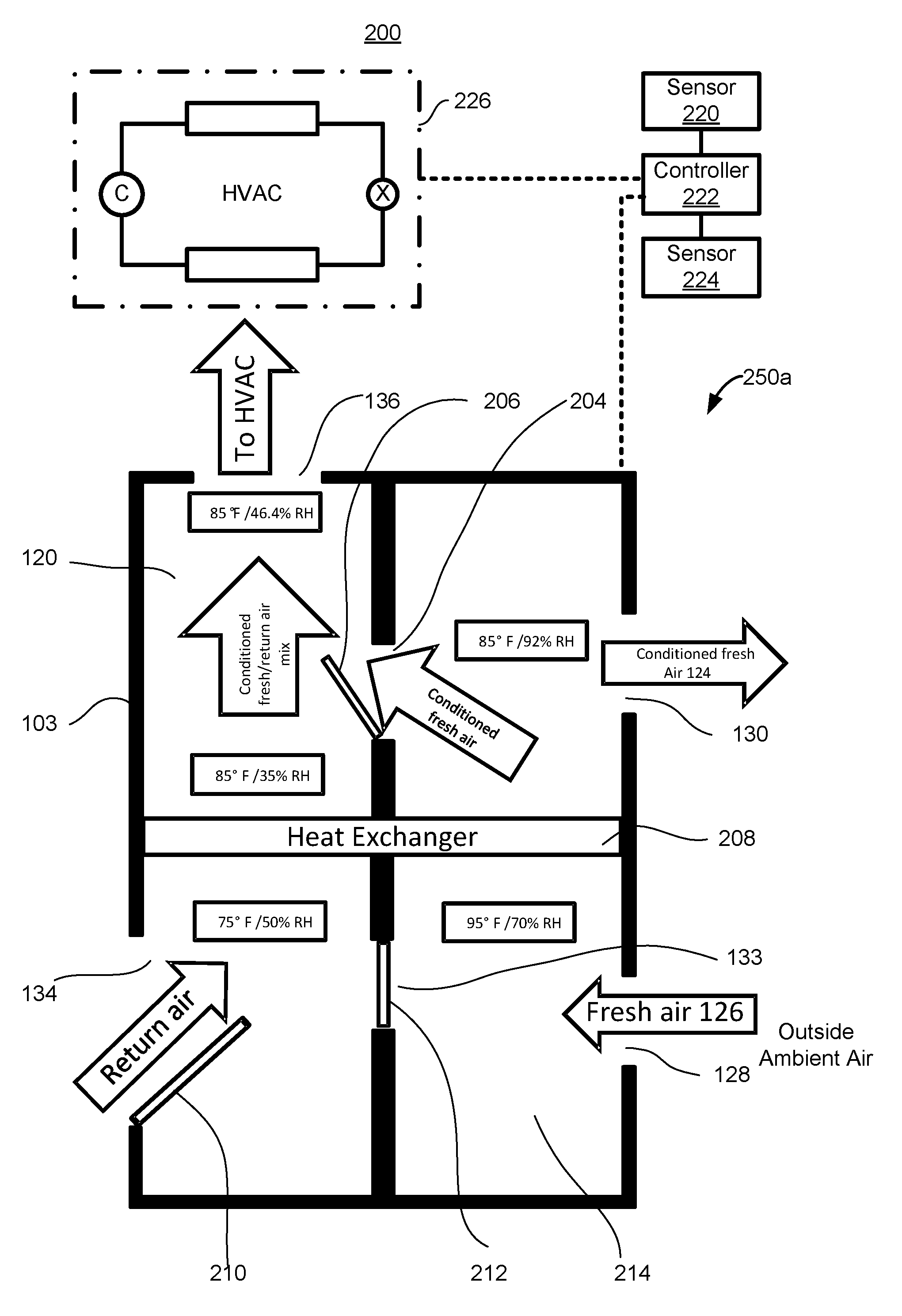
FIG. 2A is a schematic representation of an embodiment of the vehicle ventilation module in a first mode of operation;
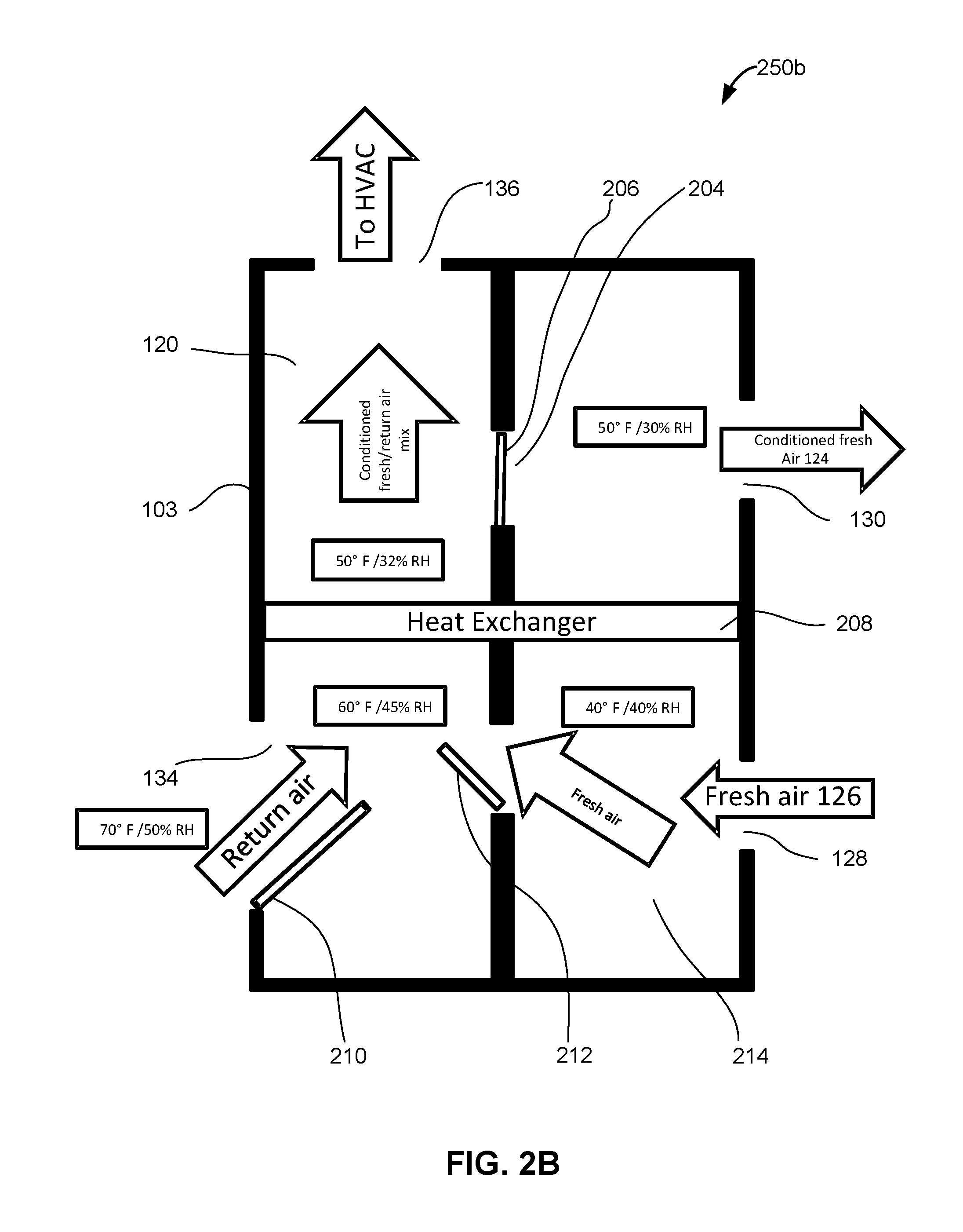
FIG. 2B is a schematic representation of the vehicle ventilation module of FIG. 2A, shown in a second mode of operation;
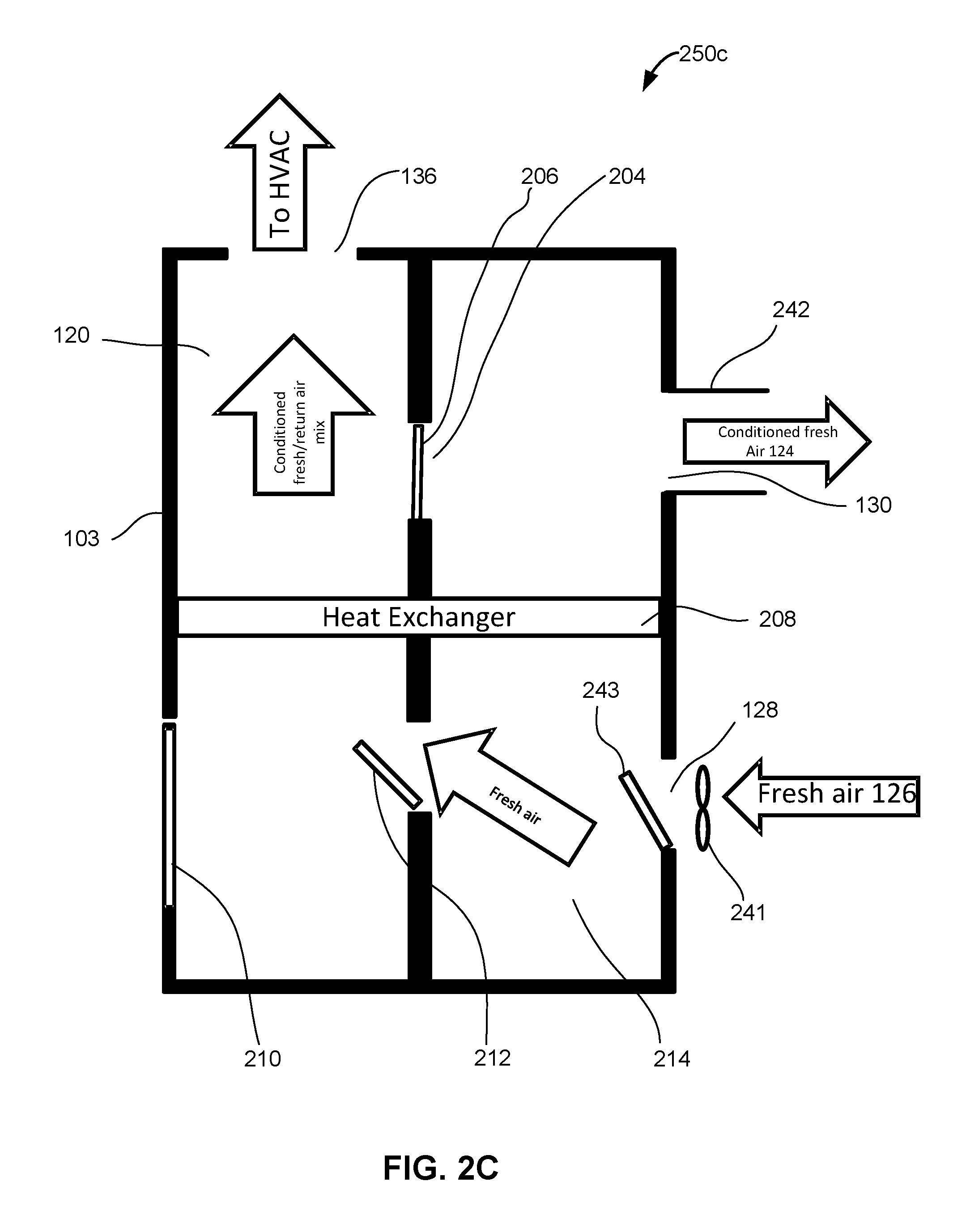
FIG. 2C is a schematic representation of the vehicle ventilation module of FIG. 2A and 2B, shown in a third mode of operation;
FIG. 3 is a flow chart of a method for conditioning air provided to an interior compartment of a vehicle;
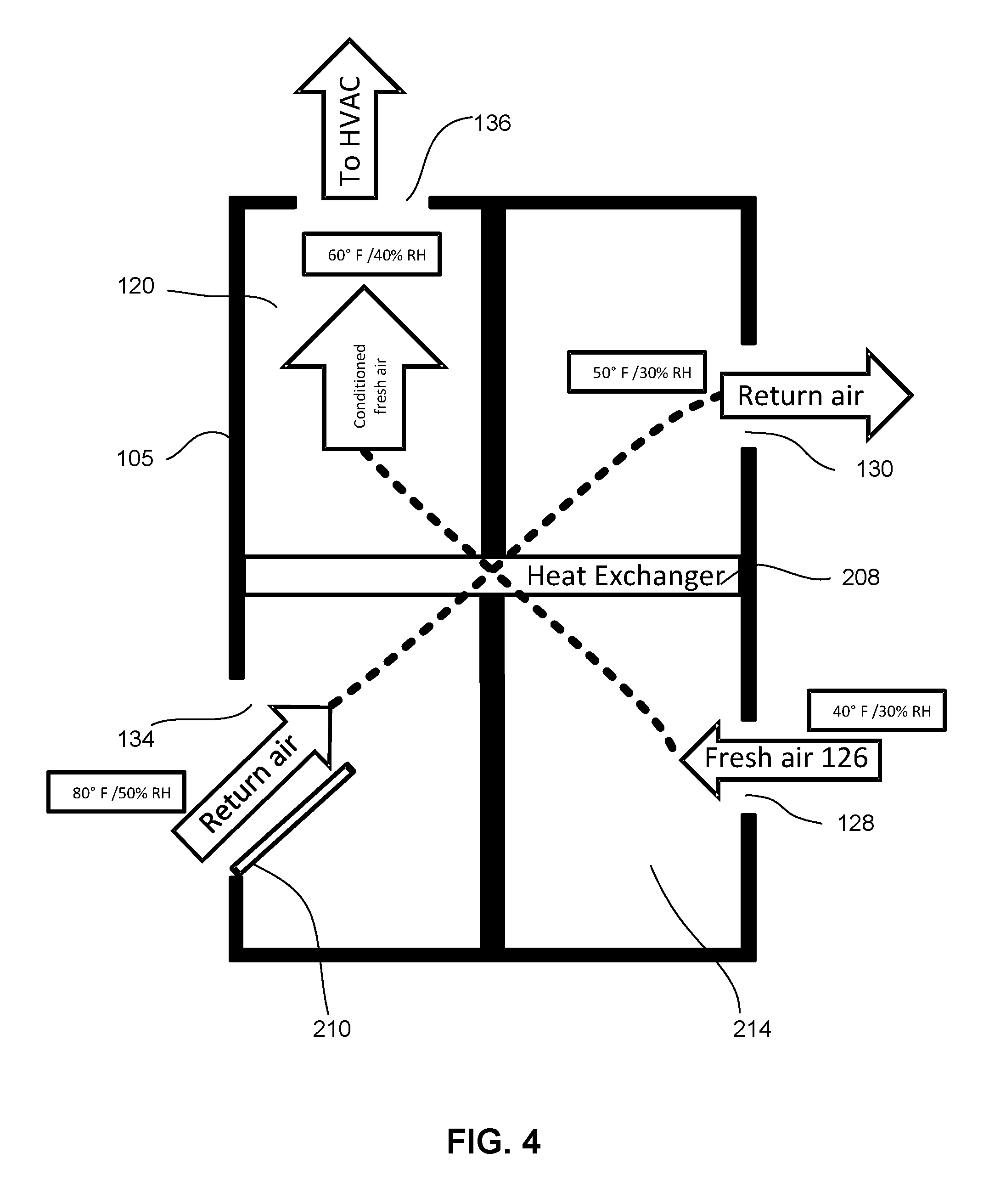
FIG. 4 is a schematic view of another embodiment of an air conditioning system utilizing heat recovery ventilation for fresh air supply and climate control according to the teachings of the present invention; and
FIG. 5 is a schematic view of another embodiment of an air conditioning system utilizing heat recovery ventilation for fresh air supply and climate control according to the teachings of the present invention.
DETAILED DESCRIPTION
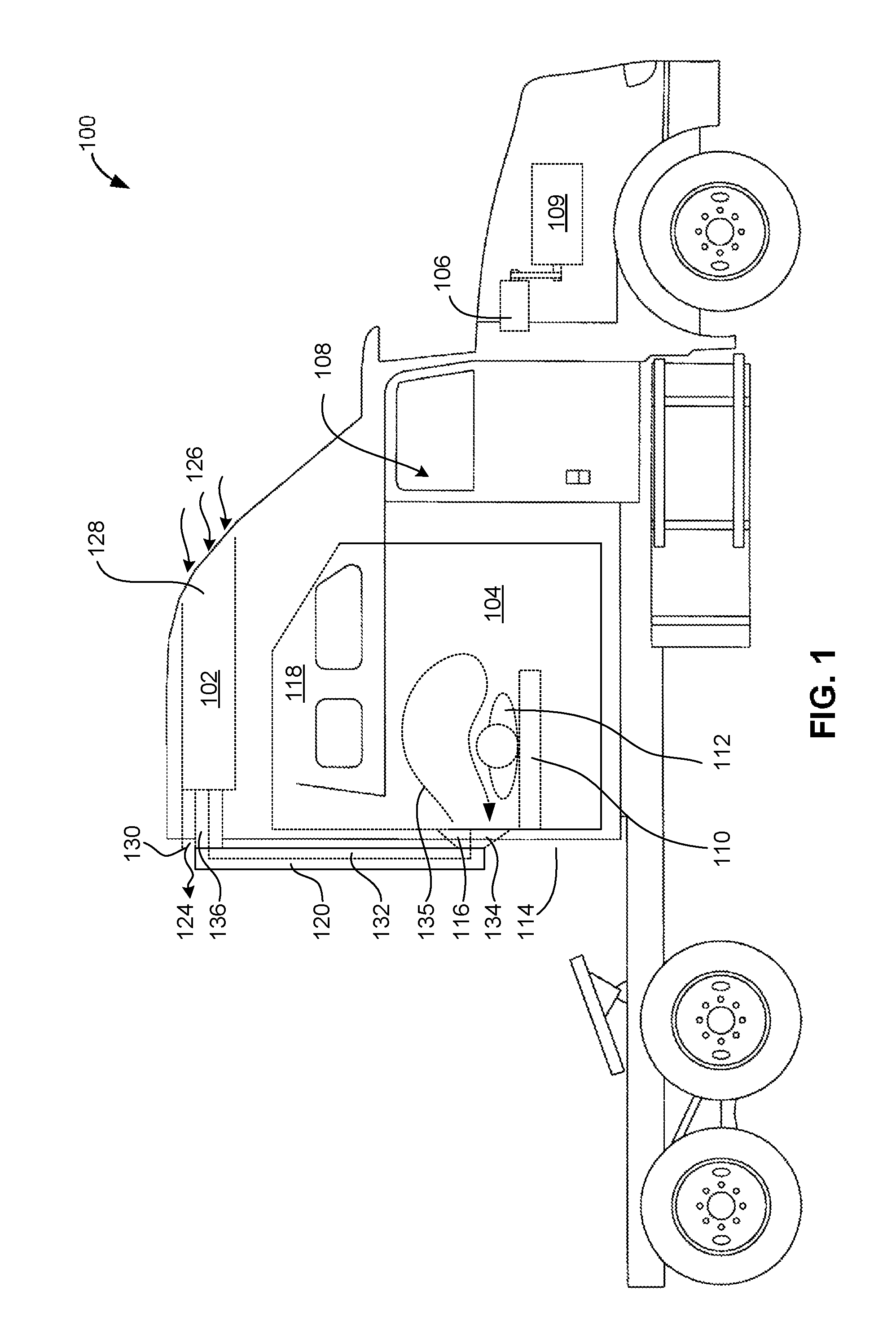
FIG. 1 is a schematic representation of an embodiment of a vehicle 100, such as an over-the-road commercial truck, with a ventilation module that utilizes heat recovery ventilation for fresh air supply. While the figures and description contemplate an over-the-road commercial vehicle, those skilled in the art will recognize that the systems and methods described herein are equally applicable to other types of vehicles.
In some embodiments the vehicle includes a cab 108. A vehicle operator may operate the vehicle 100 from within the cab 108. Some embodiments also include a sleeping area 104 containing one or more beds 110 on which the vehicle operator 112 or passenger may sleep or rest. In some embodiments, the sleeping area 104 is separated from the cab 108 by a retractable curtain or door, which may thermally separate the cab 108 from the sleeping area 104. In some embodiments, the sleeping area 104 is located within the outer shell of the vehicle cab between a back end wall 114, and a pair of sidewalls 118 extending generally perpendicular to the back end wall 114. The bed 110 is typically provided along the back end wall 114 of the sleeping area 104 with one side adjacent the back end wall 114 and two other sides or ends adjacent the sidewalls 118. Thus, three sides of the bed 110 are typically encompassed or surrounded by the shell of the sleeping area 104. This leaves an open side of the bed 110 along the front where a person can maneuver into and out of the bed 110. The bed 110 is typically elevated a few feet above the floor of the sleeping area 110.
In some embodiments, the thermal environment of the cab 108 is controlled with a primary ventilation module 106 (e.g. a heater and/or air conditioner). In some embodiments, this ventilation module 106 is a traditional belt-driven air-conditioning system mechanically coupled to the vehicle's engine 109 to operate the primary ventilation module 106 when the engine 109 is running.
In some embodiments, the vehicle 100 includes an auxiliary ventilation module 102 (e.g. a heater and/or air conditioner) to control the thermal environment of the sleeping area 104. It should, however, be appreciated that the auxiliary ventilation module 102 may heat or cool the cab 108, or any other area of the vehicle, with or without the assistance of the primary ventilation module 106.
The auxiliary ventilation module 102 includes an air outlet 116 that delivers thermally conditioned air to the sleeping area 104, such as over the bed 110, as shown. Where the sleeping area 104 includes more than one bunk bed, two outlets, one for each bed, may be provided. In the illustrated embodiment, the outlet 116 is provided along the back end wall 114. In other arrangements, the outlet 116 may be provided through the ceiling, towards one or both of the corners between the back end wall 114 and side walls 118; along the side walls 118; or at any other suitable location wherein thermally conditioned air is expelled into the sleeping area 104. The auxiliary ventilation module 102 may be mounted along the ceiling, above the cab, along the back end wall 114, beneath the bed 110, or in any other suitable location.
In some embodiments, the auxiliary ventilation module 102 includes a fresh air duct having an air inlet 128 for receiving fresh air 126 from outside the cab and sleeping area, and a fresh air outlet 130 for exhausting air 124 received through the fresh air inlet 128. In some embodiments, the fresh air inlet 128 is a scoop to direct fresh air into the fresh air duct while the vehicle is moving forward. In some embodiments, the auxiliary ventilation module 102 also includes a return duct 120 having a return air inlet 134 and a return air outlet 136.
In use, thermally conditioned air is supplied to the interior of the vehicle 100 via a supply duct 132 and supply duct outlet 116. The air circulates within the vehicle, as shown by arrow 135, and is thereafter drawn into the return air inlet 134, passes along the return duct 120 to the return duct outlet 136 where it is received by the auxiliary ventilation module 102 to be reconditioned or exhausted.
FIG. 2A is a schematic representation of an embodiment of a system 200 containing a vehicle ventilation module 103 shown in a first mode of operation 250a. (The vehicle ventilation module 103 is an exemplary embodiment of the vehicle ventilation module 102 shown in FIG. 1.) The system 200 includes any suitable heating, ventilation, and air conditioning (HVAC) system 226, such as a conventional vapor-compression refrigerant loop having a compressor, condenser, expansion valve, evaporator, refrigerant lines, fittings, condenser coils, valves, or other components for a vehicle based HVAC system. The HVAC system 226 may provide heated air, cooled air, or both, and may also include multiple air conditioning circuits or loops. For example, the HVAC system 226 may include a primary circuit with a belt driven, engine operated compressor, and a secondary circuit with an electrically driven compressor that is not dependent upon an engine for its operation. Either or both of the aforementioned circuits may be utilized to provide temperature controlled air in the system 200.
The system 200 also includes a vehicle ventilation module 103 positioned upstream from HVAC system 226. As will be described in greater detail below, the vehicle ventilation module 103 is responsible for pre-treating the air supplied to the HVAC system 226, which will ultimately be delivered to the passenger compartment (or other interior compartment) of the vehicle.
As will be explained below, the vehicle ventilation module 103 utilizes heat recovery and energy recovery ventilation to provide fresh air to the interior of the vehicle while maintaining and improving climate control. The vehicle ventilation module 103 can also transfer heat and humidity between the inside of the vehicle and the exterior of the vehicle to provide more efficient cooling and/or heating of the interior of the vehicle. The aforementioned functionality may be utilized for multi-season comfort and efficiency gains by using the lowest inlet temperature available when in a cooling mode, or utilizing heat recovery to maximize heating efficiency.
Those skilled in the art will recognize that when the HVAC system 226 is operated using an electrically driven compressor, the vehicle ventilation module 103 advantageously reduces the thermal load on the HVAC system 226, ultimately reducing the electrical power required to operate the HVAC system 226.
The system 200 also includes a controller 222 in communication with at least one sensor 220 located within the interior of the vehicle, as well as at least one sensor 224 located on the exterior of the vehicle. Sensors 220, 224 are responsible for communicating climate based information to the controller 222. As such, these sensors 220, 224 may be temperature sensors, thermostats, humidity sensors (e.g., hygrometers, sling psychrometers, etc.), air speed sensors, air quality sensors for monitoring pollutant levels such as NOx and CO, or the like.
In some embodiments, the controller 222 is also in communication with HVAC system 226, as well as the vehicle ventilation module 103, and is operable to control the respective functionalities thereof. In some embodiments, the controller 222 sends a control signal to the HVAC system 226 to initiate the operation thereof, and more particularly, initiate the operation of the engine and/or electrically operated circuit therein. In some embodiments, the controller 222 sends a control signal to the vehicle ventilation module 103 to control the amount of fresh air input into the interior of the vehicle from the vehicle ventilation module 103, as described below.
In those embodiments where the interior sensor 220 includes an air quality sensor and such a sensor detects an unacceptable amount of pollutants (e.g. NOx and/or CO) in the interior of the vehicle, the controller 222 sends a control signal that allows the input of fresh air into the vehicle, either through vehicle ventilation module 103, or by opening a door, window, or vent on the vehicle in order to allow the interior air to be exchanged with fresh exterior air. In yet another embodiment, where the interior sensor 220 includes an air quality sensor and such a sensor detects an unacceptable amount of in interior pollutants, the controller 222 may also turn on an interior air purification device (not shown), e.g., an air ionizer, which removes various forms of viruses, bacteria, pet dander, mold, mildew, or the like.
In some embodiments, where the interior sensor 220 determines that the temperature of the interior air is warmer than the exterior air (as measured by the exterior sensor 224), and the desired interior temperature is to be lowered, this same functionality is used to exchange the warmer interior air with the cooler exterior air.
The vehicle ventilation module 103 includes a return air duct 120 that includes a return air inlet 134 and a return air outlet 136 downstream of the return air inlet 134. The return air outlet 136 is thermally (and typically fluidly) coupled to the HVAC system 226. The vehicle ventilation module 103 also includes a fresh air duct 214 having a fresh air inlet 128 and a fresh air outlet 130 downstream of the fresh air inlet 128. An example of the placement and type of such ducts, inlets, and outlets is shown in FIG. 1.
The vehicle ventilation module 103 also includes a heat exchanger 208 thermally coupled to the return air duct 120 and the fresh air duct 214. The heat exchanger 208 is disposed upstream of the return air outlet 136 and the fresh air outlet 130, and downstream of the return air inlet 134 and the fresh air inlet 128. In other words, the heat exchanger 208 separates the inlets 134, 128 from the outlets 136, 130. The heat exchanger 208 may be an air-to-air heat exchanger as one example, although other types of heat exchangers could also be utilized.
The heat exchanger 208 allows heat to be transferred between the return duct 120 and the fresh air duct 214 without the air in the ducts having to make contact (although as shown below, the air in each duct mixes in certain modes). In some embodiments, the heat exchanger 208 is a metallic radiator that has a high thermal conductivity.
The vehicle ventilation module 103 also includes a first door 212 joining the return air duct 120 and the fresh air duct 214 upstream of the heat exchanger 208. These doors are otherwise known as controllable vents or dampeners. Finally, the vehicle ventilation module 103 includes a second door 206 joining the return air duct 120 and the fresh air duct 214 downstream of the heat exchanger 208. The first door 212 and the second door 206 are operable to selectively open and close in order to allow air to pass between the fresh air duct 214 and the return air duct 120. These doors 212, 206 are selectively controlled (e.g., opened and closed) by signals sent from the controller 222. In some embodiments, each door can be opened by incremental amounts to allow more or less fresh air into the return duct 120, or more or less return air into the fresh air duct 214. By controlling the doors, the ventilation module allows for the recovery of a percentage of energy normally lost through the fresh air outlet 130, so as to allow the HVAC system 226 to handle increased thermal load required for heating or cooling fresh air without requiring a dramatic increase in the thermal capacity of the HVAC system 226.
In some embodiments, optional additional doors are provided, such as the third door 210 at the return air inlet 134. Closing this door prevents return air from recirculating into the interior of the vehicle. Although not shown, when the door 210 is closed, return air is routed or exhausted to the exterior of the vehicle, rather than through the ventilation module 103. Other doors may be provided at the other inlets 128 and outlets 136, 130. For example, a fourth door (not shown) is located at the fresh air inlet 128. The fourth door is also selectively controlled (e.g., opened and closed) by signals sent from the controller 222 in order to control the amount of fresh air being introduced into the system. In some embodiments, the fourth door can be opened by incremental amounts to allow more or less fresh air into the fresh air duct 214. In some embodiments, the amount of fresh air that is introduced into the fresh air duct 214 (as modulated by the fourth door) is determined by the controller 222 based on any appropriate consideration (e.g., interior or exterior air quality levels, interior or exterior temperatures, interior or exterior humidity levels, and the like).
Also in some embodiments, one or more fans are provided at the inlets and outlets 134, 128, 204, 130, 133, 136 to assist in moving air through the inlets, outlets or ducts. In other embodiments, a flue (or Venturi tube) is connected to one or more of the outlets 136, 130 to assist in drawing air through the return duct 120 and/or fresh air duct 202.
FIG. 2B is a schematic representation of the vehicle ventilation module 103 of FIG. 2A, shown in a second mode of operation 250b, while FIG. 2C is a schematic representation of the vehicle ventilation module 103 of FIGS. 2A and 2B, shown in a third mode of operation 250c. The first to third modes of operation are discussed below with respect to FIG. 3.
FIG. 3 is a flow chart 300 of a method for conditioning air provided to an interior compartment of a vehicle. Initially, a ventilation module, such as ventilation module 102, 103, 105, and/or 107 of FIGS. 1, 2A-2C, and 4-5, is provided (302) for a vehicle. In a first mode of operation, a controller, such as controller 222 of FIG. 2A, determines: (i) it would be beneficial to provide the HVAC system with air that is at a higher temperature and/or provide the HVAC system with fresh air, and (ii) that the return air is cooler and/or has a lower relative humidity than the exterior air (304). The controller then closes the first door 212 (FIG. 2A) (or ensures that it is already closed), and opens the second door 206 (FIG. 2A) (or ensures that it is already open) (306) as shown in FIG. 2A. For example, as shown in FIG. 2A, the first door 212 is closed and the second door 206 is open when the return air is 75 degrees Fahrenheit and 50% relative humidity, and the temperature of the fresh air outside is 95 degrees Fahrenheit and 70% relative humidity. By closing the first door 212 and opening the second door 206 under these conditions, the fresh air in the fresh air duct 214 passes over the heat exchanger 208 that has been cooled by the lower temperature return air, thereby transferring some of its heat to the heat exchanger 208. The return air in the return air duct 120 also passes over the heat exchanger 208, thereby raising the temperature of the return air to 85 degrees Fahrenheit with a 35% relative humidity. Conditioned fresh air that had its temperature lowered from 95 degrees Fahrenheit, and 70% relative humidity, to 85 degrees Fahrenheit, and 92% relative humidity, by passing over the heat exchanger 208, is mixed with the conditioned return air by passing through the second door 206. Finally, the conditioned mixture of fresh and return air at 85 degrees Fahrenheit, and 46.4% relative humidity, is sent to the HVAC system, which may or may not need to further raise or lower the temperature of the air before it is sent to the interior of the vehicle.
In a second mode of operation, the controller, such as controller 222 of FIG. 2A, determines that: (i) it would be beneficial to provide the HVAC system with fresh air and/or with air having a lower temperature and/or relative humidity, and (ii) the return air is warmer and/or has a higher relative humidity than the exterior air (308). The controller then closes the second door 206 (FIG. 2B) (or ensures that it is already closed), and opens the first door 212 (FIG. 2B) (or ensures that it is already open) (310), as shown in FIG's. 2B and 3. For example, as shown in FIG. 2B, return air entering the return air duct is at 70 degrees Fahrenheit, and 50% relative humidity. The fresh air 126 introduced into the fresh air duct 214 is at 40 degrees Fahrenheit, and 40% relative humidity. The fresh air passes through the opening provided by the open first door 212 and is mixed with the return air to condition the return air to 60 degrees Fahrenheit, and 45% relative humidity. Both the partially conditioned return air in the return duct and some of the fresh air in the fresh air duct pass over the heat exchanger 208. This drops the temperature and/or relative humidity of the return air from 60 degrees Fahrenheit, and 45% relative humidity to 50 degrees Fahrenheit, and 32% relative humidity. This conditioned cooler return air is then passed to the HVAC system, which may not need to further raise or lower the temperature of the air before it is sent to the interior of the vehicle. The conditioned fresh air that passed over the heat exchanger is now at 50 degrees Fahrenheit, and 30% relative humidity, and is exhausted to the exterior of the vehicle.
In a third mode of operation, the controller, such as controller 222 of FIG. 2A, determines that the system requires introducing a high percentage (e.g., 80-100%) fresh air into the interior of the cabin (312). The controller then closes (or partially closes) the third door 210 (FIG. 2C) (or ensures that it is already closed or partially closed), and opens the first door 212 and/or the second door 206 (or ensures that they are already open) (314), as shown in FIG. 2C. By closing or opening the third door 210, the controller can control the amount of return air that is recirculated.
In some embodiments, the doors include appropriate sealing, or in the alternative, a valve, variable air flow device, or a damper. Those skilled in the art will recognize that various configurations in this regard are possible. Furthermore, additional doors or flow routing components may be included.
Turning now to FIG. 4, another vehicle ventilation module 105 is illustrated. (The vehicle ventilation module 105 is an exemplary embodiment of the vehicle ventilation module 102 shown in FIG. 1.) In this embodiment, doors 212, 206, which are included in FIGS. 2A-2C, are omitted. The other components of the vehicle ventilation module 105 are substantially the same as those described above with respect to the vehicle ventilation module 102, and the details of those components are not reproduced here. Moreover, for ease of reference, the same reference numbers are used for components that are common between the ventilation modules 102 and 105.
In the ventilation module 105, flow directing elements including but not limited to fans, dampers, valves, etc. are utilized to pull all of the return air passing through return air inlet 134 through heat exchanger 208 and out of fresh air outlet 130. Drawing the return air through the heat exchanger 208 will cause some of the heat of the return air to be transferred to the heat exchanger 208. Additional flow directing elements including but not limited to fans, dampers, valves, etc. are also situated to route all of the fresh air received through the fresh air inlet 128 through heat exchanger 208 and out of return air outlet 136. With this operation, heat will be extracted from the return air, through the heat exchanger 208, and transferred to the fresh air, resulting in pre-heated fresh air being sent to the HVAC system 226.
Specifically, as shown in FIG. 4, if the return air entering the return air duct 120 is at 80 degrees Fahrenheit, and 50% relative humidity, and the fresh air entering the fresh air duct 202 is at 40 degrees Fahrenheit, and 30% relative humidity, the heat exchanger 208 operates to increase the temperature of the incoming fresh air to 60 degrees Fahrenheit, and 40% relative humidity, thus reducing the thermal load placed on the HVAC system 226 without requiring any return air to be reintroduced into the HVAC system 226.
Turning now to FIG. 5, another vehicle ventilation module 107 is illustrated. (The vehicle ventilation module 107 is an exemplary embodiment of the vehicle ventilation module 102 shown in FIG. 1.) In this embodiment, doors 212, 206, which are included in FIGS. 2A-2C, are omitted. The other components of the vehicle ventilation module 107 are substantially the same as those described above with respect to the vehicle ventilation module 102, and the details of those components are not reproduced here. Moreover, for ease of reference, the same reference numbers are used for components that are common between the ventilation modules 102 and 107.
In this embodiment, fresh air is not utilized as supply air (i.e., no fresh air is introduced into the return air stream in the ventilation module 107). Rather, the fresh air is utilized to remove heat from heat exchanger 208, and is then exhausted through the fresh air outlet 130. This operation allows for the return air passing through return air inlet 134 to undergo heat transfer as it passes through heat exchanger 208, ultimately reducing its temperature. This reduced temperature air is then routed through return air outlet 136 to HVAC system 226. This "pre-cooled" air presents a lower thermal load on HVAC system 226.
For example, as shown in FIG. 5, if the return air entering the return air duct 120 is at 80 degrees Fahrenheit, and 50% relative humidity, and the fresh air entering the fresh air duct 202 is at 70 degrees Fahrenheit, and 90% relative humidity, the heat exchanger 208 operates to reduce the temperature of the recirculating return air to 75 degrees Fahrenheit, and 50% relative humidity, thus reducing the thermal load placed on the HVAC system 226 without requiring any fresh air to be introduced into the HVAC system 226.
FIGS. 4-5 depict ventilation modules 105, 107 that do not include the doors 212, 206 that are shown in the ventilation module 103 of FIGS. 2A-2C. In some embodiments, however, the ventilation modules 105 and 107 include the doors 212, 206. Indeed, in some embodiments, the ventilation modules 105 and 107 represent additional modes of operation of the ventilation module 103 where both the doors 212 and 206 are closed. More particularly, in some embodiments, the modes of operation shown in FIGS. 4 and 5 are achieved using the ventilation module 103 shown in FIGS. 2A-2C by closing the doors 212, 206, and manipulating one or more flow directing elements (e.g., fans, dampers, valves, etc.) of the ventilation module 103 and/or the heat exchanger 208 in order to achieve the required flow characteristics of the return air and the fresh air.
Those skilled in the art will recognize that the system(s) described above may be supplied as a stand-alone combined system including HVAC system 226 and ventilation module 102. Alternatively, ventilation module 102 may be supplied as an add-on component to an existing HVAC system 226. Moreover, all illustrated temperature and humidity values are for exemplary purposes only, and are not necessarily representative of actual temperature or humidity values, nor do the necessarily accurately reflect the thermal performance of the systems described or any of the components of the systems.
All references, including publications, patent applications, and patents cited herein are hereby incorporated by reference to the same extent as if each reference were individually and specifically indicated to be incorporated by reference and were set forth in its entirety herein.
In the foregoing discussion, plural instances are, optionally provided for components, operations, or structures described herein as a single instance. Finally, boundaries between various components, operations, and data stores are somewhat arbitrary, and particular operations are illustrated in the context of specific illustrative configurations. Other allocations of functionality are envisioned and optionally fall within the scope of the implementation(s). In general, structures and functionality presented as separate components in the example configurations are, optionally, implemented as a combined structure or component. Similarly, structures and functionality presented as a single component are, optionally, implemented as separate components. These and other variations, modifications, additions, and improvements fall within the scope of the implementation(s).
It will also be understood that, although the terms "first," "second," are, in some circumstances, used herein to describe various elements, these elements should not be limited by these terms. These terms are only used to distinguish one element from another. For example, a first contact could be termed a second contact, and, similarly, a second contact could be termed a first contact, which changing the meaning of the description, so long as all occurrences of the "first contact" are renamed consistently and all occurrences of the second contact are renamed consistently. The first contact and the second contact are both contacts, but they are not the same contact.
The terminology used herein is for the purpose of describing particular implementations only and is not intended to be limiting of the claims. As used in the description of the implementations and the appended claims, the singular forms "a", "an" and "the" are intended to include the plural forms as well, unless the context clearly indicates otherwise. It will also be understood that the term "and/or" as used herein refers to and encompasses any and all possible combinations of one or more of the associated listed items. It will be further understood that the terms "comprises" and/or "comprising," when used in this specification, specify the presence of stated features, integers, steps, operations, elements, and/or components, but do not preclude the presence or addition of one or more other features, integers, steps, operations, elements, components, and/or groups thereof.
As used herein, the term "if" is, optionally, construed to mean "when" or "upon" or "in response to determining" or "in accordance with a determination" or "in response to detecting," that a stated condition precedent is true, depending on the context. Similarly, the phrase "if it is determined (that a stated condition precedent is true)" or "if (a stated condition precedent is true)" or "when (a stated condition precedent is true)" is, optionally, construed to mean "upon determining" or "in response to determining" or "in accordance with a determination" or "upon detecting" or "in response to detecting" that the stated condition precedent is true, depending on the context.
The foregoing description included example systems, methods, techniques, instruction sequences, and computing machine program products that embody illustrative implementations. For purposes of explanation, numerous specific details were set forth in order to provide an understanding of various implementations of the inventive subject matter. It will be evident, however, to those skilled in the art that implementations of the inventive subject matter is, optionally, practiced without these specific details. In general, well-known instruction instances, protocols, structures and techniques have not been shown in detail.
The foregoing description, for purpose of explanation, has been described with reference to specific implementations. However, the illustrative discussions above are not intended to be exhaustive or to limit the implementations to the precise forms disclosed. Many modifications and variations are possible in view of the above teachings. The implementations were chosen and described in order to best explain the principles and their practical applications, to thereby enable others skilled in the art to best utilize the implementations and various implementations with various modifications as are suited to the particular use contemplated.
* * * * *
References
D00000
D00001
D00002
D00003
D00004
D00005
D00006
D00007
XML
uspto.report is an independent third-party trademark research tool that is not affiliated, endorsed, or sponsored by the United States Patent and Trademark Office (USPTO) or any other governmental organization. The information provided by uspto.report is based on publicly available data at the time of writing and is intended for informational purposes only.
While we strive to provide accurate and up-to-date information, we do not guarantee the accuracy, completeness, reliability, or suitability of the information displayed on this site. The use of this site is at your own risk. Any reliance you place on such information is therefore strictly at your own risk.
All official trademark data, including owner information, should be verified by visiting the official USPTO website at www.uspto.gov. This site is not intended to replace professional legal advice and should not be used as a substitute for consulting with a legal professional who is knowledgeable about trademark law.